EP3457717B1 - Auto-étalonnage de système de réduction de bruit à multiples microphones pour dispositifs d'assistance auditive utilisant un dispositif auxiliaire - Google Patents
Auto-étalonnage de système de réduction de bruit à multiples microphones pour dispositifs d'assistance auditive utilisant un dispositif auxiliaire Download PDFInfo
- Publication number
- EP3457717B1 EP3457717B1 EP18195599.8A EP18195599A EP3457717B1 EP 3457717 B1 EP3457717 B1 EP 3457717B1 EP 18195599 A EP18195599 A EP 18195599A EP 3457717 B1 EP3457717 B1 EP 3457717B1
- Authority
- EP
- European Patent Office
- Prior art keywords
- hearing assistance
- signal
- calibration
- auxiliary device
- user
- Prior art date
- Legal status (The legal status is an assumption and is not a legal conclusion. Google has not performed a legal analysis and makes no representation as to the accuracy of the status listed.)
- Active
Links
- 230000009467 reduction Effects 0.000 title claims description 30
- 239000013598 vector Substances 0.000 claims description 77
- 239000011159 matrix material Substances 0.000 claims description 33
- 230000005236 sound signal Effects 0.000 claims description 26
- 238000001914 filtration Methods 0.000 claims description 12
- 210000003128 head Anatomy 0.000 claims description 12
- 230000006870 function Effects 0.000 claims description 9
- 238000001228 spectrum Methods 0.000 claims description 6
- 238000012546 transfer Methods 0.000 claims description 6
- 230000003213 activating effect Effects 0.000 claims description 5
- 210000000613 ear canal Anatomy 0.000 claims description 5
- 230000000694 effects Effects 0.000 claims description 5
- 230000002238 attenuated effect Effects 0.000 claims description 4
- 238000007493 shaping process Methods 0.000 claims description 3
- 230000000007 visual effect Effects 0.000 claims description 2
- 238000000034 method Methods 0.000 description 42
- 238000012545 processing Methods 0.000 description 26
- 238000005259 measurement Methods 0.000 description 18
- 230000004044 response Effects 0.000 description 15
- 238000004891 communication Methods 0.000 description 11
- 238000004458 analytical method Methods 0.000 description 10
- 238000006243 chemical reaction Methods 0.000 description 6
- 210000005069 ears Anatomy 0.000 description 6
- 230000001419 dependent effect Effects 0.000 description 5
- 238000009826 distribution Methods 0.000 description 5
- 230000001965 increasing effect Effects 0.000 description 5
- 238000005070 sampling Methods 0.000 description 5
- 238000007476 Maximum Likelihood Methods 0.000 description 4
- 230000004913 activation Effects 0.000 description 4
- 230000003044 adaptive effect Effects 0.000 description 4
- 238000005516 engineering process Methods 0.000 description 4
- 210000001508 eye Anatomy 0.000 description 4
- 230000000977 initiatory effect Effects 0.000 description 4
- 230000008569 process Effects 0.000 description 4
- 230000036962 time dependent Effects 0.000 description 4
- 230000009466 transformation Effects 0.000 description 4
- 230000008901 benefit Effects 0.000 description 3
- 210000000988 bone and bone Anatomy 0.000 description 3
- 210000003477 cochlea Anatomy 0.000 description 3
- 210000000959 ear middle Anatomy 0.000 description 3
- 208000016354 hearing loss disease Diseases 0.000 description 3
- 230000000644 propagated effect Effects 0.000 description 3
- 210000003625 skull Anatomy 0.000 description 3
- 239000000654 additive Substances 0.000 description 2
- 230000000996 additive effect Effects 0.000 description 2
- 238000013459 approach Methods 0.000 description 2
- 230000001413 cellular effect Effects 0.000 description 2
- 230000008859 change Effects 0.000 description 2
- 238000010586 diagram Methods 0.000 description 2
- 210000003027 ear inner Anatomy 0.000 description 2
- 230000002708 enhancing effect Effects 0.000 description 2
- 238000012544 monitoring process Methods 0.000 description 2
- 238000012805 post-processing Methods 0.000 description 2
- 230000001629 suppression Effects 0.000 description 2
- 101000822695 Clostridium perfringens (strain 13 / Type A) Small, acid-soluble spore protein C1 Proteins 0.000 description 1
- 101000655262 Clostridium perfringens (strain 13 / Type A) Small, acid-soluble spore protein C2 Proteins 0.000 description 1
- 206010011878 Deafness Diseases 0.000 description 1
- 208000032041 Hearing impaired Diseases 0.000 description 1
- 101000655256 Paraclostridium bifermentans Small, acid-soluble spore protein alpha Proteins 0.000 description 1
- 101000655264 Paraclostridium bifermentans Small, acid-soluble spore protein beta Proteins 0.000 description 1
- 230000009471 action Effects 0.000 description 1
- 230000006978 adaptation Effects 0.000 description 1
- 210000003926 auditory cortex Anatomy 0.000 description 1
- 230000003190 augmentative effect Effects 0.000 description 1
- 230000005540 biological transmission Effects 0.000 description 1
- 230000015572 biosynthetic process Effects 0.000 description 1
- 210000003710 cerebral cortex Anatomy 0.000 description 1
- 210000000860 cochlear nerve Anatomy 0.000 description 1
- 230000006835 compression Effects 0.000 description 1
- 238000007906 compression Methods 0.000 description 1
- 230000003111 delayed effect Effects 0.000 description 1
- 238000001514 detection method Methods 0.000 description 1
- 210000000883 ear external Anatomy 0.000 description 1
- 238000011156 evaluation Methods 0.000 description 1
- 230000005284 excitation Effects 0.000 description 1
- 230000001747 exhibiting effect Effects 0.000 description 1
- 210000002768 hair cell Anatomy 0.000 description 1
- 230000010370 hearing loss Effects 0.000 description 1
- 231100000888 hearing loss Toxicity 0.000 description 1
- 239000007943 implant Substances 0.000 description 1
- 238000011065 in-situ storage Methods 0.000 description 1
- 230000001939 inductive effect Effects 0.000 description 1
- 239000007788 liquid Substances 0.000 description 1
- 238000004519 manufacturing process Methods 0.000 description 1
- 210000005036 nerve Anatomy 0.000 description 1
- 230000000737 periodic effect Effects 0.000 description 1
- 238000003825 pressing Methods 0.000 description 1
- 238000011160 research Methods 0.000 description 1
- 230000005477 standard model Effects 0.000 description 1
- 239000003826 tablet Substances 0.000 description 1
- 230000002123 temporal effect Effects 0.000 description 1
Images


Classifications
-
- H—ELECTRICITY
- H04—ELECTRIC COMMUNICATION TECHNIQUE
- H04R—LOUDSPEAKERS, MICROPHONES, GRAMOPHONE PICK-UPS OR LIKE ACOUSTIC ELECTROMECHANICAL TRANSDUCERS; DEAF-AID SETS; PUBLIC ADDRESS SYSTEMS
- H04R25/00—Deaf-aid sets, i.e. electro-acoustic or electro-mechanical hearing aids; Electric tinnitus maskers providing an auditory perception
- H04R25/40—Arrangements for obtaining a desired directivity characteristic
- H04R25/407—Circuits for combining signals of a plurality of transducers
-
- H—ELECTRICITY
- H04—ELECTRIC COMMUNICATION TECHNIQUE
- H04R—LOUDSPEAKERS, MICROPHONES, GRAMOPHONE PICK-UPS OR LIKE ACOUSTIC ELECTROMECHANICAL TRANSDUCERS; DEAF-AID SETS; PUBLIC ADDRESS SYSTEMS
- H04R25/00—Deaf-aid sets, i.e. electro-acoustic or electro-mechanical hearing aids; Electric tinnitus maskers providing an auditory perception
- H04R25/30—Monitoring or testing of hearing aids, e.g. functioning, settings, battery power
-
- H—ELECTRICITY
- H04—ELECTRIC COMMUNICATION TECHNIQUE
- H04R—LOUDSPEAKERS, MICROPHONES, GRAMOPHONE PICK-UPS OR LIKE ACOUSTIC ELECTROMECHANICAL TRANSDUCERS; DEAF-AID SETS; PUBLIC ADDRESS SYSTEMS
- H04R25/00—Deaf-aid sets, i.e. electro-acoustic or electro-mechanical hearing aids; Electric tinnitus maskers providing an auditory perception
- H04R25/50—Customised settings for obtaining desired overall acoustical characteristics
-
- H—ELECTRICITY
- H04—ELECTRIC COMMUNICATION TECHNIQUE
- H04R—LOUDSPEAKERS, MICROPHONES, GRAMOPHONE PICK-UPS OR LIKE ACOUSTIC ELECTROMECHANICAL TRANSDUCERS; DEAF-AID SETS; PUBLIC ADDRESS SYSTEMS
- H04R3/00—Circuits for transducers, loudspeakers or microphones
- H04R3/002—Damping circuit arrangements for transducers, e.g. motional feedback circuits
-
- A—HUMAN NECESSITIES
- A61—MEDICAL OR VETERINARY SCIENCE; HYGIENE
- A61N—ELECTROTHERAPY; MAGNETOTHERAPY; RADIATION THERAPY; ULTRASOUND THERAPY
- A61N1/00—Electrotherapy; Circuits therefor
- A61N1/18—Applying electric currents by contact electrodes
- A61N1/32—Applying electric currents by contact electrodes alternating or intermittent currents
- A61N1/36—Applying electric currents by contact electrodes alternating or intermittent currents for stimulation
- A61N1/36036—Applying electric currents by contact electrodes alternating or intermittent currents for stimulation of the outer, middle or inner ear
- A61N1/36038—Cochlear stimulation
- A61N1/36039—Cochlear stimulation fitting procedures
-
- H—ELECTRICITY
- H04—ELECTRIC COMMUNICATION TECHNIQUE
- H04R—LOUDSPEAKERS, MICROPHONES, GRAMOPHONE PICK-UPS OR LIKE ACOUSTIC ELECTROMECHANICAL TRANSDUCERS; DEAF-AID SETS; PUBLIC ADDRESS SYSTEMS
- H04R2225/00—Details of deaf aids covered by H04R25/00, not provided for in any of its subgroups
- H04R2225/41—Detection or adaptation of hearing aid parameters or programs to listening situation, e.g. pub, forest
-
- H—ELECTRICITY
- H04—ELECTRIC COMMUNICATION TECHNIQUE
- H04R—LOUDSPEAKERS, MICROPHONES, GRAMOPHONE PICK-UPS OR LIKE ACOUSTIC ELECTROMECHANICAL TRANSDUCERS; DEAF-AID SETS; PUBLIC ADDRESS SYSTEMS
- H04R2430/00—Signal processing covered by H04R, not provided for in its groups
- H04R2430/20—Processing of the output signals of the acoustic transducers of an array for obtaining a desired directivity characteristic
- H04R2430/23—Direction finding using a sum-delay beam-former
-
- H—ELECTRICITY
- H04—ELECTRIC COMMUNICATION TECHNIQUE
- H04R—LOUDSPEAKERS, MICROPHONES, GRAMOPHONE PICK-UPS OR LIKE ACOUSTIC ELECTROMECHANICAL TRANSDUCERS; DEAF-AID SETS; PUBLIC ADDRESS SYSTEMS
- H04R25/00—Deaf-aid sets, i.e. electro-acoustic or electro-mechanical hearing aids; Electric tinnitus maskers providing an auditory perception
- H04R25/55—Deaf-aid sets, i.e. electro-acoustic or electro-mechanical hearing aids; Electric tinnitus maskers providing an auditory perception using an external connection, either wireless or wired
- H04R25/558—Remote control, e.g. of amplification, frequency
Definitions
- the present application relates to hearing assistance device comprising a noise reduction system and in particular to hearing assistance system for calibrating a noise reduction system of a hearing assistance device.
- Embodiments of the disclosure may e.g. be useful in applications such as hearing assistance devices, e.g. hearing aids, headsets, ear phones, active ear protection systems, etc.
- hearing assistance devices e.g. hearing aids, headsets, ear phones, active ear protection systems, etc.
- Noise reduction systems in hearing aids traditionally consist of two signal processing components:
- predetermined predetermined
- the fixed beamformers are typically implemented by forming linear combinations of the input (microphone) signals.
- the problem to be solved in the present disclosure is essentially how to determine the coefficients of these linear combinations, i.e., the fixed beamformer weights, in a manner, which is optimized to the physical characteristics of the hearing aid user.
- the fixed (or predetermined) beamformer weights may be determined off-line so that they realize certain prescribed spatial filtering characteristics. For example, in a minimum variance distortion-less response (MVDR) beamformer, it is desirable to implement a beam pattern, which has a gain of 0 dB in a certain direction, e.g., the frontal. In other cases, it is of interest to implement a target-cancelling beamformer, i.e., a beamformer which has a spatial null in the direction of the target, see e.g. [Kjems&Jensen; 2012] for an example.
- MVDR minimum variance distortion-less response
- Truly optimal beamformer weights are a function of several factors, including the physical characteristics of the user such as head shape and size, location and size of the pinnae, haircut, but also microphone locations, hearing aid shells, etc.
- the fixed beamformer weights have been estimated, e.g. using a head-and-torso simulator (e.g. Head and Torso Simulator (HATS) 4128C from Brüel & Kj ⁇ r Sound & Vibration Measurement A/S) by the hearing aid manufacturer and stored in a hearing aid memory.
- HATS Head and Torso Simulator
- the fixed beamformer weights are tailored to the HATS-model, i.e., exhibiting some sort of average human physical characteristics.
- the problem is that fixed beamformers implemented like this are close-to-optimal for a HATS-model, but not for a specific hearing aid user.
- the present disclosure proposes a way for finding the optimal beamformer weights based on the physical appearance of the individual hearing aid user.
- US7995771B1 deals with a system and method for generating a beamforming signal.
- a beam forming signal is generated by disposing a first microphone and a second microphone in horizontal coplanar alignment.
- the first and second microphones are used to detect a known signal to generate a first response and a second response.
- the first response is processed along a first signal path communicatively linked to the first microphone
- the second response is processed along a second signal path communicatively linked to the second microphone.
- the first and second responses are matched, and the matched responses are combined to generate the beamforming signal on a combined signal path.
- US7995771B1 discloses a method of matching two microphones and providing a beamformed signal based thereon.
- US2013094664A1 aims at providing a method and device which in particular make it possible to compensate for phase disturbances (e.g. due to reflections (reverberation)).
- VAN VEEN B D ET AL "Beamforming: a versatile approach to spatial filtering", IEEE ASSP MAGAZINE, IEEE, US, vol. 5, no. 2, 1 April 1988 (1988-04-01), pages 4-24, XP011437205, ISSN: 0740-7467, DOI: 10.1109/53.665 provides an overview of beamforming from a signal processing perspective with an emphasis on recent research.
- An object of the present application is adapt a noise reduction system of a hearing assistance device to a particular user.
- a further object of embodiments of the application is to facilitate an adaptation to be made by the manufacturer, at a dispenser, or by a user him- or herself.
- a hearing assistance system :
- an object of the application is achieved by a hearing assistance system comprising a hearing assistance device and an auxiliary device as defined in claim 1.
- An advantage of the present disclosure is that a calibration of the multi-microphone system is facilitated.
- calibration is made on a number of different 'typical' persons physical or artificial (e.g. models, dolls, e.g. a standard model, e.g. HATS), e.g. representing a typical child, a typical female, and a typical male person, and/or for a number of (typical) head sizes and/ or forms and/or hair styles, and/or ear positions/sizes, and/or ages.
- a standard model e.g. HATS
- head sizes and/ or forms and/or hair styles, and/or ear positions/sizes, and/or ages can be taken into account, such as position of the hearing assistance device(s) on the head, clothing, e.g. a scarf, a hat, etc.
- the resulting settings are then e.g.
- the hearing assistance device comprising the noise reduction system is mounted on the person in question (e.g. on such 'typical persons').
- the person is the 'end-user' of the hearing assistance device.
- 'beamforming' is taken to mean to (provide) a 'spatial filtering' of a number of inputs sensor signals with the aim of attenuating signal components from certain angles relative to signal components from other angles in a resulting beamformed signal.
- 'Beamforming' is taken to include the formation of linear combinations of a number of sensor input signals (e.g. microphone signals), e.g. on a time-frequency unit basis, e.g. in a predefined or dynamic/adaptive procedure.
- the system is adapted to establish a communication link between the hearing assistance device and the auxiliary device to provide that information (e.g. control and status signals, e.g. related to the calibration procedure, possibly audio signals) can be exchanged or forwarded from one to the other.
- information e.g. control and status signals, e.g. related to the calibration procedure, possibly audio signals
- the vector element di(k,m) is typically a complex number for a specific frequency (k) and time unit (m).
- the auxiliary device comprises the user interface for activating the calibration mode.
- the user interface for activating a calibration mode is distributed between the hearing assistance device and the auxiliary device.
- the calibration mode is activated in the hearing assistance device via an activation element in or on the hearing assistance device.
- the calibration mode is activated in the auxiliary device via an activation element in or on the auxiliary device.
- the hearing assistance device and said auxiliary device are adapted to establish a wireless link between them.
- the hearing assistance device comprises a wireless receiver for receiving data from the auxiliary device.
- the auxiliary device comprises a wireless transmitter for transmitting data to the hearing assistance device.
- audio processing system is configured to allow control signals for activating the calibration mode in the hearing assistance device to be transmitted from the auxiliary device to the hearing assistance device via the wireless link.
- the hearing assistance system is adapted to communicate one or more of the start time of the calibration signal, the chosen location of the auxiliary device relative to the user, and characteristics of the calibration signal to the hearing assistance device.
- the calibration signal has a duration in time, a level and frequency content allowing an acoustic transfer function at relevant frequencies (apart from a scaling factor) from the auxiliary device to each of the input units to be determined.
- the acoustic transfer function between the output transducer of the auxiliary device and a given input unit of the hearing assistance device depends on the acoustic propagation path (including the distance and acoustic propagation properties of the user's head and body).
- the calibration signal has a predefined duration in time, e.g.
- the measurement of the propagated calibration signal is performed in the duration time.
- the calibration signal comprises a broadband signal comprising all frequencies of interest, e.g. frequencies between a minimum and a maximum frequency, e.g. a sub-range in the range between 20 Hz and 8 kHz.
- the calibration signal comprises a pulse or a train of pulses, e.g. a periodic train of pulses, e.g. with a repetition frequency ⁇ 20 Hz.
- the distance in time between successive pulses is larger than the reverberation time of the location where the calibration is performed (e.g. In an embodiment, the duration of the pulse is smaller than or equal to 2 ms, e.g. ⁇ 1 ms.
- the calibration signal comprises a white noise signal of a predefined duration, e.g. ⁇ 1 s.
- the hearing assistance system is configured to determine filter weights for one or more fixed beamformers based on said estimate of a look vector d (k,m).
- a number of pre-determined sets of look vectors d pd each set encompassing look vectors estimated for different directions ( ⁇ , ⁇ ), and ranges (
- ) x (defined by vector r xsrc from the user, cf.
- r cal , person ). If/when a close match is found for a front look vector for a given person-type, the look vector corresponding to ( ⁇ , ⁇ ,
- the hearing assistance system is configured to determine filter weights for one or more fixed beamformers based an assumption of the spatial noise distribution.
- the distribution of the noise is assumed to be spatially isotropic (e.g. spherically or cylindrically isotropic).
- the distribution of the noise is assumed to originate exclusively from a predefined angle segment relative to (e.g. to the rear of) the user.
- the fixed beamformers comprise:
- the hearing assistance device further comprises a single channel post-processing filter unit operationally coupled to said multi-channel beamformer filtering unit and configured to provide an enhanced signal ⁇ (k,m).
- the multi-channel variable beamformer filtering unit comprises an MVDR filter providing filter weights w mvdr (k,m), said filter weights w mvdr (k,m) being based on a look vector d (k,m) and an inter-input unit covariance matrix R vv (k,m) for the noise signal.
- MVDR is an abbreviation of Minimum Variance Distortion-less Response, Distortion-less indicating that the target direction is left unaffected; Minimum Variance: indicating that signals from any other direction than the target direction is maximally suppressed).
- An aim of the single channel post filtering process is to suppress noise components from the target direction (which has not been suppressed by the spatial filtering process (e.g. an MVDR beamforming process). It is a further aim to suppress noise components during when the target signal is present or dominant as well as when the target signal is absent.
- the single channel post filtering process is based on an estimate of a target signal to noise ratio for each time-frequency tile (m,k).
- the estimate of the target signal to noise ratio for each time-frequency tile (m,k) is determined from the beamformed signal and the target-cancelled signal.
- the hearing assistance system comprises a control unit configured to compare beamformer weights w cal (k,m) resulting from the calibration to a set of default beamformer weights w pd (k,m) and to provide a difference measure.
- the hearing assistance system is adapted to provide that default beamformer weights are used, if the difference measure is above a predefined threshold.
- the default beamformer weights w pd (k,m) (stored in a memory of the hearing assistance device(s)) are used, if the difference measure indicative of a difference between two sets of filter weights is above a predefined threshold (e.g. defined by a statistical distance measure).
- the hearing assistance system comprises a noise estimation unit for estimating a current background noise in the calibration mode of operation of the system (in particular during the calibration of the beamformer, i.e. when the calibration signal is played by the auxiliary device).
- the default beamformer weights are used, if the ambient noise is above a predefined threshold level.
- the hearing assistance system is configured to provide that the calibration signal is adapted to the current noise level and/or spectrum, by shaping the calibration signal to ensure a predetermined (minimum) calibration signal to noise ratio (at least over a predefined frequency range, such as all frequencies) and/or the duration in time of the calibration signal.
- the level and/or spectrum of the background noise is monitored, e.g. by the auxiliary device, e.g. as a first action of the calibration procedure (before the calibration signal is formed and played via the output transducer of the auxiliary device).
- the resulting look vector determined based on the received calibration signal is accepted and stored in a memory of the hearing assistance device, if said level and/or spectrum of the current background noise is within acceptable limits.
- the calibration sound is shaped (e.g. in level, frequency, and/or temporal characteristics, e.g. duration) to take account of the current background noise (e.g. to provide a certain minimum (calibration) signal to noise ratio at all or at relevant frequencies), and to estimate the covariance matrix R ss right after each impulse to reduce impact of reverberation, cf. FIG. 4 .
- the measurement is discarded (no look vector is stored), if the noise level is above a predetermined threshold value (e.g. at predetermined frequencies).
- Kjems&Jensen; 2012 describe various aspects of noise covariance matrix estimation in a multi-microphone speech configuration.
- an estimate of the noise covariance matrix termed R ⁇ vv,diffuse ( k,m ) is predetermined and stored in a memory of the hearing assistance device.
- the noise covariance matrix reflects the known (or assumed) information regarding the spatial distribution of the noise (spatial fingerprint of the noise).
- R ⁇ vv,diffuse ( k,m ) is one such noise covariance matrix assuming a diffuse (spatially isotropic) noise.
- Other noise covariance matrices may be used as the case may be, e.g. R ⁇ vv,rear ( k,m ) assuming noise only from the rear of the user.
- the inter-input unit covariance matrix R ⁇ ss of the noisy signal s is a sum of the inter-input unit covariance matrix R xx of the target signal x and the inter-input unit covariance matrix R vv of the noise signal.
- At least one of the M input units comprises a microphone. In an embodiment, a majority, such as all, of the M input units comprises a microphone. In an embodiment, M is equal to two. In an embodiment, M is larger than or equal to three. In an embodiment, a first one of the M input units is located in an audio processing device (e.g. a hearing assistance device). In an embodiment, at least one of the other M input units is located a distance to the first input unit that is larger than a maximum outer dimension of the audio processing device where the first input unit is located. In an embodiment, a first of the M input unit is located in a first audio processing device and a second of the M input units is located in another device, the audio processing device and the other device being configured to establish a communication link between them.
- an audio processing device e.g. a hearing assistance device
- the inter-input unit covariance matrices are estimated by a maximum likelihood based method (cf. e.g. [Kjems&Jensen; 2012]).
- the audio processing system is configured to make maximum likelihood estimates of the inter input unit covariance matrix R ⁇ ss (k,m) of the noisy signal based on a number D of observations.
- the hearing assistance system comprises a voice activity detector for estimating whether or not a target signal is present or dominating at a given point in time.
- the method comprises estimating whether or not a target signal is present or dominating at a given point in time, e.g. using a voice activity detector.
- the spatial fingerprint of the noise signal e.g. noise covariance matrices
- the spatial fingerprint of the target signal e.g. look vectors
- the method comprises estimating whether or not a voice (e.g. speech) is present or dominating at a given point in time.
- the auxiliary device comprises an audio gateway device, a mobile telephone, or a computer. In an embodiment, the auxiliary device comprises or forms part of a fitting system. In an embodiment, the auxiliary device comprises a portable communication device, e.g. a SmartPhone or a tablet computer. In an embodiment, the auxiliary device comprises a remote control device for the hearing assistance device.
- the hearing assistance system comprises a sensor for allowing a user a) to locate the auxiliary device at a predetermined angle and/or height and/or distance relative to the user and/or b) to track the location of the auxiliary device relative to the user. Deciding on the correct location of the external device may be done manually by the user or automatically by the device, e.g. using gyroscopes, accelerometers, a camera with visual feedback from the user (e.g. eye tracking), etc., in the device.
- the hearing assistance system is adapted to provide a frequency dependent gain to compensate for a hearing loss of a user.
- the hearing assistance device comprises a signal processing unit for enhancing the input signals and providing a processed output signal.
- the hearing assistance device comprises an output transducer for converting an electric signal to a stimulus perceived by the user as an acoustic signal.
- the output transducer comprises a number of electrodes of a cochlear implant or a vibrator of a bone conducting hearing device.
- the output transducer comprises a receiver (speaker) for providing the stimulus as an acoustic signal to the user.
- the hearing assistance device are portable device, e.g. a device comprising a local energy source, e.g. a battery, e.g. a rechargeable battery.
- a local energy source e.g. a battery, e.g. a rechargeable battery.
- the hearing assistance device comprises a forward or signal path between an input transducer (microphone system and/or direct electric input (e.g. a wireless receiver)) and an output transducer.
- the signal processing unit is located in the forward path.
- the signal processing unit is adapted to provide a frequency dependent gain according to a user's particular needs.
- the left and right hearing assistance device comprises an analysis path comprising functional components for analyzing the input signal (e.g. determining a level, a modulation, a type of signal, an acoustic feedback estimate, etc.).
- some or all signal processing of the analysis path and/or the signal path is conducted in the frequency domain.
- some or all signal processing of the analysis path and/or the signal path is conducted in the time domain.
- the hearing assistance device comprises an analogue-to-digital (AD) converter to digitize an analogue input with a predefined sampling rate, e.g. 20 kHz.
- the hearing assistance devices comprise a digital-to-analogue (DA) converter to convert a digital signal to an analogue output signal, e.g. for being presented to a user via an output transducer.
- AD analogue-to-digital
- DA digital-to-analogue
- the hearing assistance device e.g. the input unit, e.g. a microphone unit, and or a transceiver unit, comprise(s) a TF-conversion unit for providing a time-frequency representation of an input signal.
- the time-frequency representation comprises an array or map of corresponding complex or real values of the signal in question in a particular time and frequency range.
- the TF conversion unit comprises a filter bank for filtering a (time varying) input signal and providing a number of (time varying) output signals each comprising a distinct frequency range of the input signal.
- the TF conversion unit comprises a Fourier transformation unit for converting a time variant input signal to a (time variant) signal in the frequency domain.
- the frequency range considered by the hearing assistance device from a minimum frequency f min to a maximum frequency f max comprises a part of the typical human audible frequency range from 20 Hz to 20 kHz, e.g. a part of the range from 20 Hz to 12 kHz.
- a signal of the forward and/or analysis path of the hearing assistance device is split into a number NI of frequency bands, where NI is e.g. larger than 5, such as larger than 10, such as larger than 50, such as larger than 100, such as larger than 500, at least some of which are processed individually.
- the hearing assistance device comprises a level detector (LD) for determining the level of an input signal (e.g. on a band level and/or of the full (wide band) signal).
- the input level of the electric microphone signal picked up from the user's acoustic environment is e.g. a classifier of the environment.
- the level detector is adapted to classify a current acoustic environment of the user according to a number of different (e.g. average) signal levels, e.g. as a HIGH-LEVEL or LOW-LEVEL environment.
- the hearing assistance device comprises an acoustic (and/or mechanical) feedback detection and/or suppression system.
- the hearing assistance device further comprises other relevant functionality for the application in question, e.g. compression, etc.
- the hearing assistance device comprises a listening device, e.g. a hearing aid, e.g. a hearing instrument, e.g. a hearing instrument adapted for being located at the ear or fully or partially in the ear canal of a user, or for being fully or partially implanted in the head of a user, a headset, an earphone, an ear protection device or a combination thereof.
- a listening device e.g. a hearing aid, e.g. a hearing instrument, e.g. a hearing instrument adapted for being located at the ear or fully or partially in the ear canal of a user, or for being fully or partially implanted in the head of a user, a headset, an earphone, an ear protection device or a combination thereof.
- a 'hearing assistance device' refers to a device, such as e.g. a hearing instrument or an active ear-protection device or other audio processing device, which is adapted to improve, augment and/or protect the hearing capability of a user by receiving acoustic signals from the user's surroundings, generating corresponding audio signals, possibly modifying the audio signals and providing the possibly modified audio signals as audible signals to at least one of the user's ears.
- a 'hearing assistance device' further refers to a device such as an earphone or a headset adapted to receive audio signals electronically, possibly modifying the audio signals and providing the possibly modified audio signals as audible signals to at least one of the user's ears.
- Such audible signals may e.g. be provided in the form of acoustic signals radiated into the user's outer ears, acoustic signals transferred as mechanical vibrations to the user's inner ears through the bone structure of the user's head and/or through parts of the middle ear as well as electric signals transferred directly or indirectly to the cochlear nerve of the user.
- the hearing assistance device may be configured to be worn in any known way, e.g. as a unit arranged behind the ear with a tube leading radiated acoustic signals into the ear canal or with a loudspeaker arranged close to or in the ear canal, as a unit entirely or partly arranged in the pinna and/or in the ear canal, as a unit attached to a fixture implanted into the skull bone, as an entirely or partly implanted unit, etc.
- the hearing assistance device may comprise a single unit or several units communicating electronically with each other.
- a hearing assistance device comprises an input transducer for receiving an acoustic signal from a user's surroundings and providing a corresponding input audio signal and/or a receiver for electronically (i.e. wired or wirelessly) receiving an input audio signal, a signal processing circuit for processing the input audio signal and an output means for providing an audible signal to the user in dependence on the processed audio signal.
- an amplifier may constitute the signal processing circuit.
- the output means may comprise an output transducer, such as e.g. a loudspeaker for providing an air-borne acoustic signal or a vibrator for providing a structure-borne or liquid-borne acoustic signal.
- the output means may comprise one or more output electrodes for providing electric signals.
- the vibrator may be adapted to provide a structure-borne acoustic signal transcutaneously or percutaneously to the skull bone.
- the vibrator may be implanted in the middle ear and/or in the inner ear.
- the vibrator may be adapted to provide a structure-borne acoustic signal to a middle-ear bone and/or to the cochlea.
- the vibrator may be adapted to provide a liquid-borne acoustic signal to the cochlear liquid, e.g. through the oval window.
- the output electrodes may be implanted in the cochlea or on the inside of the skull bone and may be adapted to provide the electric signals to the hair cells of the cochlea, to one or more hearing nerves, to the auditory cortex and/or to other parts of the cerebral cortex.
- a 'hearing assistance system' refers to a system comprising one or two hearing assistance devices
- a 'binaural hearing assistance system' refers to a system comprising two hearing assistance devices and being adapted to cooperatively provide audible signals to both of the user's ears.
- Hearing assistance systems or binaural hearing assistance systems may further comprise 'auxiliary devices', which communicate with the hearing assistance devices and affect and/or benefit from the function of the hearing assistance devices.
- Auxiliary devices may be e.g. remote controls, audio gateway devices, mobile phones, public-address systems, car audio systems or music players.
- Hearing assistance devices, hearing assistance systems or binaural hearing assistance systems may e.g. be used for compensating for a hearing-impaired person's loss of hearing capability, augmenting or protecting a normal-hearing person's hearing capability and/or conveying electronic audio signals to a person.
- connection or “coupled” as used herein may include wirelessly connected or coupled.
- the term “and/or” includes any and all combinations of one or more of the associated listed items. The steps of any method disclosed herein do not have to be performed in the exact order disclosed, unless expressly stated otherwise.
- FIG. 1 shows a scenario allowing a user ( U ) of a hearing assistance device ( HAD ) to perform a self-calibration of beamformer weights of a noise reduction system, using an external (auxiliary) device ( AD ) comprising a loudspeaker ( SPK ).
- the auxiliary device ( AD ) and the hearing assistance device(s) ( HAD ) are configured to allow the establishment of a wireless link between them (e.g. to inform the hearing assistance device about the initiation of a calibration procedure).
- the external (auxiliary) device (AD) comprises or is constituted by a mobile phone. Alternatively, it may form part of a fitting system.
- the aim of the activity is to calibrate the noise reduction system in the (or each) hearing assistance device ( HAD ) by playing a calibration sound ( TstSo ) from the external device ( AD ) that is captured by the input units ( MIC ) of the hearing assistance device or each of the hearing assistance devices in case the user ( U ) wears a binaural hearing assistance device system.
- additional microphones whose signals are transmitted to corresponding input units of the hearing assistance device
- may be located in other devices than the hearing assistance device itself e.g. in a communication device worn by the user (e.g. an audio gateway or a cellular telephone), in a wireless microphone, or the like).
- An advantage of the in-situ determined beamformer weights is that they implement an individualized beamformer, which is optimal for the hearing assistance device user ( U ) in question. Specifically, this procedure results in fixed beamformers designed to take into account the physical characteristics of the user ( U ), e.g. the head ( Head ), the ears ( Ear ), the body ( Torso ), the hair style, etc. Such characteristics of a user may further change across time, in particular for children, but also for adults (e.g. hair cuts, etc.). The exact location of the hearing assistance device(s) may differ slightly from day to day. The microphones of the hearing assistance device(s) may not have exactly the same characteristics as the microphones used by the hearing assistance device manufacturer, when determining the default hard-wired beamformer weights, such characteristics may further drift across time, etc.
- the calibration routine may preferably be equipped with a safety procedure:
- the beamformer weights resulting from the calibration routine may be compared to a set of default beamformer weights. If for example the two sets of weights are very different, the calibration routine may be declared invalid, and the default weights are used. The same may be the case, if the ambient noise is above a predefined threshold level.
- FIG. 2A and FIG. 2b show exemplary block diagrams of respective embodiments of a hearing assistance device (HAD) comprising a multi input unit (e.g. a multi-microphone) noise reduction system ( NRS ) (here shown with M input units, e.g. microphone units).
- the multi input unit noise reduction system ( NRS ) comprises a multi input beamformer filter unit ( BF in FIG. 2A and 2B , e.g. a minimum variance distortion-less response (MVDR) beamformer) followed by a single-channel noise reduction system ( SC-NR in FIG. 2A and 2B ).
- MVDR minimum variance distortion-less response
- the beamformer ( BF ) provides a beamformed signal Y with a gain of 0 dB, when a signal is received from the target direction / location.
- the embodiment of FIG. 2B further comprises a target-cancelling beamformer filter unit ( TC-BF ) providing a target-cancelling beamformed signal, which ideally rejects (in practice attenuates maximally) a signal played from the target direction/location.
- the target-cancelling beamformer filter unit potentially comprises several (up to M-1) target cancelling beamformers.
- the target-cancelling beamformer filter unit ( TC-BF ) provides control signal NoTr indicative of the noise present in the beamformed signal Y and configured to control the single channel post-filtering unit ( SC-NR ).
- the signals depend on time and frequency indices ( m,k ), cf. analysis filter bank units ( AFB ) in each input unit IU i , connected to each input elements ( IT i ), e.g. an input transducer such as a microphone.
- Input sound signals s 1 (n), ..., s M (n) received at respective input unit IU 1 , ..., IU M are thus provided in a time-frequency representation as signals S 1 (k,m), ..., S M (k,m).
- independent beamforming and single-channel post-filter operations are carried out for each frequency band ( k ).
- the hearing assistance device further comprises antenna and transceiver circuitry ( ANT, RF-RxlTx ) for establishing a wireless communication link to the auxiliary device ( AD in FIG. 1 ), e.g. for receiving a calibration control signal CNT from the auxiliary device.
- the calibration control signal ( CalC ) fed from the transceiver circuitry ( RF-Rx / Tx ) to the look vector determination unit ( LV-Det ) comprises a 'start calibration procedure' indication from the auxiliary (calibration) device ( AD ).
- the auxiliary device contains the calibration sound source (speaker), e.g. forming part of a dedicated calibration system (e.g. a fitting system) or a portable communication device, e.g.
- the auxiliary device sends the CNT ( CalC ) signal (e.g. at the request of a user), the auxiliary device subsequently emits the calibration sound TsTSo.
- the hearing assistance device HID
- the hearing assistance device receives the 'START of calibration' indication, it prepares for the measurement of the received calibration sound (e.g. to monitor and evaluate the background noise and to measure the received response signals caused by the calibration sound TsTSo a predefined time after the reception of the 'start calibration procedure' signal). Based on the evaluation of the background noise, measurement may be stopped (if the background noise level is too high), or the calibration signal may be modified in magnitude at different frequencies (shaped) and/or the duration of the measurement period may be adapted (e.g.
- the look vector determination unit ( LV-Det ) determines a current look-vector based on the microphone signals ( S 1 , ..., S M ) representing the calibration-signal TstSo.
- the unit LV-Det determines the look vector (according to an example not falling under scope of the claims (transfer functions from the calibration sound source to each of the input units (e.g. microphones) or scaled versions thereof) for the direction to (and distance to) the auxiliary device relative to each of the input units of the user's hearing assistance device(s) ( HAD ).
- the look vector is stored in a memory ( MEM ) of the hearing assistance device.
- the resulting look vector d is fed to the beamformer (if the result of the background noise measurement is acceptable).
- the multi input unit noise reduction system ( NRS ) may comprise a beamformer ( BF ) with a predetermined (e.g. periodically fixed, e.g. after a calibration) spatial target fingerprint (e.g. look vector) and a fixed spatial noise fingerprint (e.g. noise covariance matrix), cf. FIG. 2A . It may alternatively comprise a beamformer ( BF ) with a predetermined spatial target fingerprint and a variable spatial noise fingerprint (e.g. target-cancelling beamformer TC-BF, FIG: 2B ). Finally, the multi input unit noise reduction system ( NRS ) may comprise adaptive beamformers for implementing variable spatial target and noise fingerprints.
- a predetermined spatial target fingerprint e.g. periodically fixed, e.g. after a calibration
- a fixed spatial noise fingerprint e.g. noise covariance matrix
- the NRS system makes use of the output of pre-determined (calibrated) beamformers, which can be formulated in terms of two quantities (which are frequency dependent): A look vector d ( k ) ⁇ C M and a noise covariance matrix R vv ( k ) ⁇ C M x M , where C M is the set of M-dimensional complex vectors, and C MxM is the set of MxM-dimensional complex matrices.
- the proposed self-calibration routine is a method for estimating the look vector d ( k ) .
- the noise covariance matrix whose estimate is called R ⁇ vv,diffuse ( k ) (assuming isotropic noise) is predetermined and stored in a memory of the hearing assistance device device (cf. e.g. MEM of FIG. 2 ).
- the look vector d(k) is estimated as follows.
- the calibration sound ( TstSo in FIG. 1 ) is emitted by the external device ( AD-SPK of AD in FIG. 1 )
- the resulting inter-microphone covariance matrix R ⁇ ss ( k ) for microphones Mic 1 Mic 2 is estimated for each frequency k:
- R ⁇ ss k 1 N ⁇ m s m k s H m k
- s ( m,k ) [ s ( m,k, 1) s ( m,k, 2)] T
- s ( m,k,i ) is the output of the analysis filter bank for microphone i, at time frame m and frequency index k, and N is the number of time frames considered in the estimation.
- our look vector estimate d ⁇ ( k ) is defined as the eigen vector corresponding to the largest eigen value of the estimated target covariance matrix R ⁇ ss ( k ).
- 2 1.
- the look vector estimate d ( k ) thus encodes the physical direction and distance of the target source, it is therefore also called the look direction.
- the look vector may be normalized to have a '1' at the position of the reference input unit (e.g. a reference microphone).
- predetermined (calibrated) beamformers may be found in terms of the estimated look vector d ⁇ ( k ) and the noise covariance matrix R ⁇ vv,diffuse ( k ) as follows (wherein it is assumed that the look vector as well as the noise covariance matrix are predetermined).
- MVDR minimum variance distortionless response
- '1' refers to microphone #1 as the reference microphone.
- NRS noise reduction system
- W R ( k ) is a target-cancelling beamformer.
- a front hyper-cardioid beamformer ( FIG. 2A , alternative to enhanced omni ) is, in fact, the MVDR beamformer for the situation where the noise field is diffuse (that is, homogenous and spherically isotropic). We approximate this noise condition with a situation where the noise is cylindrically isotropic.
- the self-calibration procedure may e.g. result in the determination filter coefficients of three optimal, individualized (calibrated) beamformers:
- the fixed beamformers w EO ( k ), W R ( k ), W H ( k ) are determined based on estimate R ⁇ ss ( k ) of the target signal covariance matrix, and estimates R ⁇ vv ( k ) of the inter-microphone covariance of the noise field. Instead of estimating these quantities via batch estimation as used above, they may be updated recursively.
- the idea described above is to estimate beamformers "pointing" at the location of the calibration signal.
- the enhanced omni beamformer w EO ( k ) has unit gain for signals originating from the location of the calibration source, and the target-cancelling beamformer W R ( k ) completely eliminates signals from this direction.
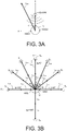
- the calibration signal originates from the frontal direction (0 degrees) and a range of 1 m (cf. r cal in FIG. 3A ), but we are interested in determining the weights of beamformers pointing towards 30 degrees, 2 m (cf. r xsrc in FIG.
- FIG. 3A shows a number of pre-determined sets of look vectors d, each set encompassing look vectors estimated for different (direction ( ⁇ ), range (
- FIG. 3B shows a number of predefined orientations of the look vector relative to a user.
- (p a, b).
- the sound source S s is located in the same plane as the microphones of the left and right hearing assistance devices ( HAD l and HAD r ).
- predefined look vectors (and/or filter weights) for the respective multi-channel beamformer filtering units of the multi-input unit noise reduction systems of the left and right hearing assistance devices are determined in advance and stored in a memory of the left and right hearing assistance devices (cf. e.g. MEM in FIG. 2 ).
- the density of predefined angles is larger in the front half plane than in the rear half plane.
- ⁇ j a number of distances r sq,p may be defined, in FIG. 5 two different distances, denoted a and b (r sqb ⁇ 2 ⁇ r sqa ), are indicated.
- any number of predefined angles and distances may be defined in advance and corresponding look vectors and/or filter weights determined and stored in a memory of the respective left and right hearing assistance devices (or be accessible from a common database of the binaural hearing assistance system, e.g. located in an auxiliary device, e.g. a SmartPhone).
- the user interface is implemented as an APP of a SmartPhone.
- the predefined look vectors (or beamformer weights) may e.g. be determined prior to normal operation of the hearing aid device by measurement for different directions and distances on a model user, e.g.
- HATS Head and Torso Simulator 4128C from Brüel & Kj ⁇ r Sound & Vibration Measurement A/S 'equipped' with first and second hearing assistance devices.
- Different physical or model users may be used to determine look vectors for different persons (e.g. different size heads, different hair styles, etc.).
- the predetermined look vectors may preferably be stored in a memory of the hearing assistance device(s), e.g. prior to its fitting to a particular user (e.g. during manufacturing).
- a look vector for a location of a target sound source relative to a user defined by vector r xsrc in FIG. 3A (during normal use of the hearing assistance device), one approach could be to compare the front look vector d cal determined for distance r cal based on the available calibration signal (according to the present disclosure) by comparison with the front look vectors stored in memory ( d pd ( ⁇ ,
- the new look vector for the desired (angle, range) pair may be estimated from the known look vector in a probabilistic setting.
- the look vectors measured for a given fixed position (angle, range) for different persons may be modelled as realizations of an M dimensional random variable, e.g., distributed according to an M-dimensional, complex-valued Gaussian distribution.
- look vectors measured at different positions are jointly Gaussian, it is possible to find minimum mean-square error, maximum a posteriori, or maximum likelihood estimates of the unknown look vector.
- the external device emits an acoustic calibration signal
- the hearing assistance device(s) estimate the inter-microphone covariance matrix R ss ( k ) and subsequently the look vector d(k) based on the resulting microphone signals.
- this calibration is performed in a reverberant-free environment, but peoples' homes are generally reverberant. Therefore, a calibration method, which is robust to reverberation is of interest. Such a method could be devised when using a click train as calibration signal.
- the estimate may be based on time regions immediately after a click is emitted, such that the wavefront impinging on the microphones is included when estimating R ss ( k ) but such that any possible reflections of this wavefront is not.
- a click train comprising a multitude N TRAIN of individual click pulses (indicated by the three click pulses ( Click ) separated by the broken time line, symbolising the option of an arbitrary number of clicks) would allow to have sufficiently many terms in the sum to achieve a reliable estimate of R ss ( k ).
- the distance in time between successive clicks is larger than the reverberation time (e.g. parameter T60) of the specific acoustic environment of the measurements.
- the total measurement time T M is adapted to the current background noise level.
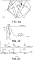
- FIG. 4A schematically shows an example of an acoustically propagated signal from an audio source ( S in FIG. 4A ) to a listener ( L in FIG. 4A ) via direct ( p 0 ) and reflected propagation paths ( p 1 , p 2 , p 3 , p 4 , respectively) in an exemplary location ( Room ).
- the resulting acoustically propagated signal received by a listener e.g. via a hearing assistance device worn by the listener (at L in FIG. 4A ) is a sum of the five (and possibly more, depending on the room) differently delayed and attenuated (and possibly otherwise distorted) contributions.
- the direct ( p 0 ) propagation path is indicated FIG.
- FIG. 4A schematically illustrates an example of a resulting time variant sound signal (magnitude
- the direct part of the signal ( p 0 , dashed part of the graph) appear at the location of the hearing assistance device (@ L ) ⁇ T pd after it was played by the auxiliary device ( S ).
- FIG. 4C illustrates a measurement procedure for calibrating a noise reduction system NRS according to the present disclosure, wherein a calibration signal (TstSo in FIG. 1 ) in the form of a click pulse (a single- or multi-frequency sound of short duration, as e.g. used in auditory diagnostic measurements, e.g. ABR) or a train of click pulses ( Click in FIG. 4C ) is played by the loudspeaker ( AD-SPK in FIG. 1 ) of the auxiliary device ( AD in FIG. 1 ).
- the input units e.g. MIC in FIG. 1 , or IU 1 , ..., IU M of FIG. 2
- HAD hearing assistance device
- a target covariance matrix R ss ( k ) E [ s ( m,k ) s H ( m,k )] is estimated based on the signal components received during a first part ( ⁇ T M in FIG. 4c ) of the time interval between two successive pulses, where the direct part of the impulse response IR of the click pulse is present in the signals received at the input units (as indicated in the schematic impulse responses IR of the click pulses in the upper part of FIG. 4C , the impulse responses IR being equivalent to the one illustrated and discussed in connection with FIG. 4B ).
- the measurement time ⁇ T M around the peak of the direct signal part p 0 is around 1 ms.
- the propagation delay ⁇ T pd of the calibration signal from the source to the listener is around 3 ms (corresponding to a distance of approximately 1 m).
- the auxiliary device informs the hearing assistance device about the start time of the calibration signal to allow the hearing assistance device to initiate the measurement period at an appropriate time relative to the arrival of the direct part of the signal.
- the auxiliary device informs the hearing assistance device about characteristics of the calibration signal allowing the hearing assistance device to determine a transfer function from the sound source to the input unit in question (and thus to determine a look vector d ).
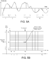
- FIG. 5 schematically shows a conversion of a signal in the time domain to the time-frequency domain
- FIG. 5a illustrating a time dependent sound signal (amplitude versus time) and its sampling in an analogue to digital converter
- FIG. 5b illustrating a resulting 'map' of time-frequency units after a (short-time) Fourier transformation of the sampled signal.
- FIG. 5a illustrates a time dependent sound signal x(n) (amplitude versus time (n)), its sampling in an analogue to digital converter and a grouping of time samples in frames, each comprising N s samples.
- the graph showing a Amplitude versus time may e.g. represent the time variant analogue electric signal provided by an input transducer, e.g. a microphone, before being digitized by an analogue to digital conversion unit.
- FIG. 5B illustrates a 'map' of time-frequency units resulting from a Fourier transformation (e.g. a discrete Fourier transform, DFT) of the input signal of FIG.
- a Fourier transformation e.g. a discrete Fourier transform, DFT
- a given frequency band is assumed to contain one (generally complex) value of the signal in each time frame. It may alternatively comprise more than one value.
- the terms 'frequency range' and 'frequency band' are used in the present disclosure.
- a frequency range may comprise one or more frequency bands.
- Each frequency band ⁇ f k is indicated in FIG. 5B to be of uniform width. This need not be the case though.
- the frequency bands may be of different width (or alternatively, frequency channels may be defined which contain a different number of uniform frequency bands, e.g. the number of frequency bands of a given frequency channel increasing with increasing frequency, the lowest frequency channel(s) comprising e.g. a single frequency band).
- the time intervals ⁇ t m (time unit) of the individual time-frequency bins are indicated in FIG. 5B to be of equal size. This need not be the case though, although it is assumed in the present embodiments.
- a time unit is e.g. of the order of ms in an audio processing system.
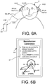
- FIG. 6 shows an exemplary application scenario of an embodiment of a hearing assistance system according to the present disclosure
- FIG. 6A illustrating a user, a binaural hearing aid system and an auxiliary device during a calibration procedure of the noise reduction system
- FIG. 6B illustrating the auxiliary device running an APP for initiating the calibration procedure.
- FIG. 6A shows an embodiment of a binaural hearing aid system comprising left (second) and right (first) hearing assistance devices ( HAD l , HAD r ) in communication with a portable (handheld) auxiliary device ( AD ) functioning as a user interface ( UI ) for the binaural hearing aid system.
- the binaural hearing aid system comprises the auxiliary device AD (and the user interface UI ) .
- the user interface UI of the auxiliary device AD is shown in FIG. 6B .
- the user interface comprises a display (e.g. a touch sensitive display) displaying a user of the hearing assistance system and a number of predefined locations of the calibration sound source relative to the user. Via the display of the user interface (under the heading Beamformer calibration ), the user U is instructed to
- FIG. 7 shows an embodiment of an auxiliary device AD according to the present disclosure.
- the auxiliary device AD comprises a microphone ( AD-MIC ) for picking up a sound signal from the environment, e.g. a noise signal ( Noise ) during or prior to a calibration procedure.
- the sound signal is converted to an electric input signal IN, which is communicated to a signal processing unit (SPU) and to a noise detector ( ND ) for monitoring the (noise) input signal IN (e.g. detecting a level and/or analysing a frequency content, etc.).
- a resulting noise analysis signal Nas e.g.
- a control unit ( CONT ) for controlling the calibration procedure, including generating a calibration signal CalS (possibly shaped in frequency, e.g. modified in level and/or duration in time dependent on the noise analysis signal Nas ) .
- the (electric) calibration signal CalS is converted to a calibration sound signal TstSo by loudspeaker ( AD-SPK ).
- the control unit ( CONT ) receives a signal ( Start ) from the user interface ( UI ) indicating that the user has activated the START 'button' (cf. FIG. 6B ), which initiates the calibration procedure.
- the control unit ( CONT ) Prompted by the Start signal, the control unit ( CONT ) generates calibration control signal CalC, which is transmitted to the hearing assistance device(s) (e.g. HAD l , HAD r in FIG. 6A ) via transceiver and antenna circuitry ( RF-Rx / Tx, ANT, signal CNT, and wireless link WL-RF ).
- the activation of the START 'button' via user interface UI brings the auxiliary device (from a NORMAL mode) into a CALIBRATION mode and generates control signals Mode to selection unit ( SEL ) , Start to control unit ( CONT ), and UC to signal processing unit (SPU).
- the Mode signal controls the selector ( SEL ) selecting calibration signal CalS as output signal OUT (input signal to the loudspeaker, AD-SPK ), when the CALIBRATION mode is activated, and the normal processed signal PRSfrom the signal processing unit (SPU), when the NORMAL mode is activated.
- the control signal UC may inhibit the normal processing in the signal processing unit (SPU) when the CALIBRATION mode is activated. Further, the control signal UC may carry information data intended for being presented to the user from the signal processing unit (SPU) to the user interface ( UI ) . In an embodiment, the user is informed about the result of the analysis of the noise analysis, e.g. if a noise level is above a noise level threshold via the user interface (cf. dashed signal Nas in FIG. 7 from noise detector ND to user interface UI ) . Thereby, the user may be discouraged from executing the calibration procedure while a noise level is too high.
- communication between the hearing assistance device and the auxiliary device is in the base band (audio frequency range, e.g. between 0 and 20 kHz).
- communication between the hearing assistance device and the auxiliary device is based on some sort of modulation at frequencies above 100 kHz.
- frequencies used to establish a communication link between the hearing assistance device and the auxiliary device is below 70 GHz, e.g. located in a range from 50 MHz to 70 GHz, e.g. above 300 MHz, e.g. in an ISM range above 300 MHz, e.g.
- the wireless link is based on a standardized or proprietary technology.
- the wireless link is based on Bluetooth technology (e.g. Bluetooth Low-Energy technology) or a related technology.
- wireless links denoted IA-WL e.g. an inductive link between the hearing left and right assistance devices
- WL-RF e.g. RF-links (e.g. Bluetooth) between the auxiliary device AD and the left HAD l , and between the auxiliary device AD and the right HAD r , hearing assistance device, respectively
- IA-WL e.g. an inductive link between the hearing left and right assistance devices
- WL-RF e.g. RF-links (e.g. Bluetooth) between the auxiliary device AD and the left HAD l , and between the auxiliary device AD and the right HAD r , hearing assistance device, respectively
- the auxiliary device AD is or comprises an audio gateway device adapted for receiving a multitude of audio signals (e.g. from an entertainment device, e.g. a TV or a music player, a telephone apparatus, e.g. a mobile telephone or a computer, e.g. a PC) and adapted for selecting and/or combining an appropriate one of the received audio signals (or combination of signals) for transmission to the hearing assistance device.
- the auxiliary device is or comprises a remote control for controlling functionality and operation of the hearing assistance device(s).
- the function of a remote control is implemented in a SmartPhone, the SmartPhone possibly running an APP allowing to control the functionality of the audio processing device via the SmartPhone (the hearing assistance device(s) comprising an appropriate wireless interface to the SmartPhone, e.g. based on Bluetooth or some other standardized or proprietary scheme).
- a SmartPhone may comprise
Landscapes
- Physics & Mathematics (AREA)
- Engineering & Computer Science (AREA)
- Acoustics & Sound (AREA)
- Signal Processing (AREA)
- Health & Medical Sciences (AREA)
- General Health & Medical Sciences (AREA)
- Otolaryngology (AREA)
- Neurosurgery (AREA)
- Circuit For Audible Band Transducer (AREA)
Claims (20)
- Système d'assistance auditive comprenant un dispositif d'assistance auditive (HAD) configuré pour être porté par un utilisateur (U) et un dispositif auxiliaire (AD) ;• le dispositif d'assistance auditive (HAD) comprenant
HD-a) une multitude M d'unités d'entrée IUi , i = 1, ..., M, dont l'une d'elles est une unité d'entrée de référence, chacune de la multitude d'unités d'entrée étant adaptée pour fournir une représentation temps-fréquence Si(k,m) d'un signal si(n) au niveau d'une ième unité d'entrée dans un nombre de bandes de fréquences et un nombre d'instances temporelles, k étant un indice de bande de fréquences, m étant un indice temporelle, n représentant le temps et M étant supérieur ou égal à deux ; et
HD-b) un système de réduction de bruit à multiples unités d'entrées (NRS) comprenant une unité de filtrage de formeur de faisceaux multicanaux (Formeur de faisceau) couplée fonctionnellement à ladite multitude d'unités d'entrée IUi, i = 1, ..., M, et configurée pour déterminer les poids de formeur de faisceaux w(k,m) destinés à fournir un signal formé par faisceau Y(k,m), lesdites composantes de signal en provenance d'autres directions qu'une direction d'une source de signal cible étant atténuées, tandis que les composantes de signal provenant de la direction de la source de signal cible sont laissées non atténuées ou sont moins atténués que les composantes de signal provenant desdites autres directions ;• le système d'assistance auditive comprenant une interface utilisateur (UI) destinée à activer un mode d'étalonnage dans le dispositif auxiliaire (AD) et dans le dispositif d'assistance auditive (HAD) ;• le dispositif auxiliaire (AD) comprenant
AD-a) un transducteur de sortie (AD-SPK) destiné à convertir un signal électrique représentatif d'un son en un signal sonore acoustique ;
AD-b) une unité de commande (CONT) destinée à transmettre un signal d'étalonnage électrique (CalS) au transducteur de sortie (AD-SPK) lorsque ledit mode d'étalonnage est activé ;
ledit dispositif d'assistance auditive (HAD), durant ledit mode d'étalonnage, étant configuré pour• fournir ladite représentation temps-fréquence Si(k,m) du signal sonore d'étalonnage si(n) reçu au niveau de ladite ième unité d'entrée, i = 1, 2, ..., M, et pour• fournir un vecteur de regard estimé d̂ (k,m) pour un signal cible provenant d'une source de signal cible située au niveau d'un emplacement spécifique par rapport à l'utilisateur (U) uniquement sur la base des signaux si(n), qui définissent les signaux d'étalonnage électriques tels qu'ils sont reçus au niveau des unités d'entrée IUi , le signal d'étalonnage étant converti par le transducteur de sortie (AD-SPK) du dispositif auxiliaire (AD) en un signal sonore d'étalonnage acoustique (TstSO) reçu au niveau desdites unités d'entrée, ledit emplacement spécifique par rapport à l'utilisateur (U) étant l'emplacement dudit transducteur de sortie (AD-SPK) du dispositif auxiliaire (AD), et ledit vecteur de regards estimé d̂ (k,m) étant un vecteur à M dimensions comprenant les éléments di (i = 1, 2, ..., M), le ième élément di(k,m) définissant une fonction de transfert acoustique relative de la ième unité d'entrée (IUi) vers ladite unité d'entrée de référence, et pour• déterminer les poids optimaux de formeur de faisceau destinés à être utilisés pour déterminer ledit signal formé par faisceau Y(k,m) sur la base dudit vecteur de regard estimé d̂ (k,m). - Système d'assistance auditive selon la revendication 1, ledit dispositif auxiliaire (AD) comprenant ladite interface utilisateur (UI) destinée à activer le mode d'étalonnage.
- Système d'assistance auditive selon la revendication 1 ou 2, ledit dispositif d'assistance auditive (HAD) et ledit dispositif auxiliaire (AD) étant adaptés pour établir une liaison sans fil entre eux.
- Système d'assistance auditive selon la revendication 3, adapté pour communiquer, au dispositif d'assistance auditive (HAD), l'un ou plusieurs de l'horaire de début du signal d'étalonnage et de l'emplacement spécifique du dispositif auxiliaire (AD) par rapport à l'utilisateur (U).
- Système d'assistance auditive selon l'une quelconque des revendications 1 à 4, configuré pour déterminer les poids de formeur de faisceau pour un ou plusieurs formeurs de faisceau fixes sur la base de ladite estimation d̂ (k,m) du vecteur de regard d (k,m).
- Système d'assistance auditive selon l'une quelconque des revendications 1 à 5, ledit système de réduction de bruit à multiples unités d'entrée (NRS) comprenant un formeur de faisceau (BF) avec une empreinte de cible spatiale préétablie fixée périodiquement, et soit• une empreinte de bruit spatiale fixe, soit• une empreinte de bruit spatiale variable.
- Système d'assistance auditive selon la revendication 6, ladite empreinte de cible spatiale fixé périodiquement, préétablie, étant représentée par un vecteur de regard estimé d̂ (k,m) après un mode d'étalonnage, et ladite empreinte de bruit spatiale fixe ou variable étant représentée par une matrice de covariance de bruit R̂ vv(k,m).
- Système d'assistance auditive selon l'une quelconque des revendications 1 à 7, configuré pour assurer que le signal d'étalonnage est adapté à un niveau de bruit et/ou à un spectre actuel, en façonnant le signal d'étalonnage pour garantir un rapport signal d'étalonnage-bruit préétabli et/ou la durée dans le temps du signal d'étalonnage.
- Système d'assistance auditive selon l'une quelconque des revendications 5 à 8, ledit ou lesdits formeurs de faisceaux fixes étant déterminés à partir du vecteur de regard estimé d̂ (k,m) et d'une estimation de la matrice de covariance inter unités d'entrée R̂ vv(k,m) du bruit vi impactant les unités d'entrée respectives (i = 1, 2, ..., M).
- Système d'assistance auditive selon la revendication 9, une estimation de la matrice de covariance du bruit, nommée R̂ vv,diffuse(k,m), étant préétablie et stockée dans une mémoire (MEM) du dispositif d'assistance auditive (HAD).
- Système d'assistance auditive selon l'une quelconque des revendications 1 à 10, comprenant un détecteur d'activité vocale destiné à estimer si oui ou non un signal cible est présent ou dominant à un instant donné.
- Système d'assistance auditive selon l'une quelconque des revendications 1 à 11, ledit dispositif auxiliaire (AD) comprenant une télécommande, un dispositif de passerelle audio, un téléphone mobile ou un ordinateur, par exemple un ordinateur tablette.
- Système d'assistance auditive selon l'une quelconque des revendications 1 à 12, ledit dispositif auxiliaire (AD) comprenant ou faisant partie d'un système d'appareillage.
- Système d'assistance auditive selon l'une quelconque des revendications 1 à 13, ledit dispositif auxiliaire (AD) étant un dispositif portable, par exemple portatif.
- Système d'assistance auditive selon l'une quelconque des revendications 1 à 14, comprenant un capteur pour permettre à un utilisateur a) de localiser le dispositif auxiliaire (AD) à un angle et/ou à une hauteur et/ou à une distance prédéfinis par rapport à l'utilisateur (U) et/ou b) de suivre l'emplacement du dispositif auxiliaire (AD) par rapport à l'utilisateur (U).
- Système d'assistance auditive selon la revendication 15, ledit dispositif auxiliaire (AD) comprenant une caméra fournissant une rétroaction visuelle, par exemple un suivi oculaire, de l'utilisateur (U) concernant un emplacement correct du dispositif auxiliaire (AD).
- Système d'assistance auditive selon l'une quelconque des revendications 1 à 16, ledit dispositif d'assistance auditive (HAD) comprenant un appareil auditif adapté pour être situé au niveau de l'oreille ou entièrement ou partiellement dans le conduit auditif d'un utilisateur (U), ou pour être totalement ou partiellement implanté dans la tête d'un utilisateur (U), un micro-casque, un écouteur, un dispositif de protection auditive ou une combinaison de ceux-ci.
- Système d'assistance auditive selon l'une quelconque des revendications 1 à 17, comprenant une unité de commande configurée pour comparer les poids de formeur de faisceau wcal(k,m) résultant de l'étalonnage à un ensemble de poids de formeur de faisceau par défaut wpd(k,m) et pour fournir une mesure de la différence.
- Système d'assistance auditive selon la revendication 18, adapté pour assurer que des poids de formeur de faisceau par défaut sont utilisés, si la mesure de différence est supérieure à un seuil prédéfini.
- Système d'assistance auditive selon l'une quelconque des revendications 1 à 19, ledit vecteur de regard d(k,m) étant estimé à partir d'une matrice de covariance inter-unités d'entrée R̂ss(k,m) sur la base des signaux Si(k,m), i = 1, 2, ..., M reçus au niveau des unités d'entrée respectives (IUi) lorsque le signal d'étalonnage est lu par le transducteur de sortie (AD-SPK) du dispositif auxiliaire (AD).
Applications Claiming Priority (2)
| Application Number | Priority Date | Filing Date | Title |
|---|---|---|---|
| EP14163499.8A EP2928211A1 (fr) | 2014-04-04 | 2014-04-04 | Auto-étalonnage de système de réduction de bruit à multiples microphones pour dispositifs d'assistance auditive utilisant un dispositif auxiliaire |
| EP15160514.4A EP2928215A1 (fr) | 2014-04-04 | 2015-03-24 | Auto-étalonnage de système de réduction de bruit à multiples microphones pour dispositifs d'assistance auditive utilisant un dispositif auxiliaire |
Related Parent Applications (2)
| Application Number | Title | Priority Date | Filing Date |
|---|---|---|---|
| EP15160514.4A Division EP2928215A1 (fr) | 2014-04-04 | 2015-03-24 | Auto-étalonnage de système de réduction de bruit à multiples microphones pour dispositifs d'assistance auditive utilisant un dispositif auxiliaire |
| EP15160514.4A Previously-Filed-Application EP2928215A1 (fr) | 2014-04-04 | 2015-03-24 | Auto-étalonnage de système de réduction de bruit à multiples microphones pour dispositifs d'assistance auditive utilisant un dispositif auxiliaire |
Publications (2)
| Publication Number | Publication Date |
|---|---|
| EP3457717A1 EP3457717A1 (fr) | 2019-03-20 |
| EP3457717B1 true EP3457717B1 (fr) | 2021-08-04 |
Family
ID=50424135
Family Applications (3)
| Application Number | Title | Priority Date | Filing Date |
|---|---|---|---|
| EP14163499.8A Withdrawn EP2928211A1 (fr) | 2014-04-04 | 2014-04-04 | Auto-étalonnage de système de réduction de bruit à multiples microphones pour dispositifs d'assistance auditive utilisant un dispositif auxiliaire |
| EP18195599.8A Active EP3457717B1 (fr) | 2014-04-04 | 2015-03-24 | Auto-étalonnage de système de réduction de bruit à multiples microphones pour dispositifs d'assistance auditive utilisant un dispositif auxiliaire |
| EP15160514.4A Ceased EP2928215A1 (fr) | 2014-04-04 | 2015-03-24 | Auto-étalonnage de système de réduction de bruit à multiples microphones pour dispositifs d'assistance auditive utilisant un dispositif auxiliaire |
Family Applications Before (1)
| Application Number | Title | Priority Date | Filing Date |
|---|---|---|---|
| EP14163499.8A Withdrawn EP2928211A1 (fr) | 2014-04-04 | 2014-04-04 | Auto-étalonnage de système de réduction de bruit à multiples microphones pour dispositifs d'assistance auditive utilisant un dispositif auxiliaire |
Family Applications After (1)
| Application Number | Title | Priority Date | Filing Date |
|---|---|---|---|
| EP15160514.4A Ceased EP2928215A1 (fr) | 2014-04-04 | 2015-03-24 | Auto-étalonnage de système de réduction de bruit à multiples microphones pour dispositifs d'assistance auditive utilisant un dispositif auxiliaire |
Country Status (4)
| Country | Link |
|---|---|
| US (1) | US9591411B2 (fr) |
| EP (3) | EP2928211A1 (fr) |
| CN (1) | CN104980870B (fr) |
| DK (1) | DK3457717T3 (fr) |
Families Citing this family (73)
| Publication number | Priority date | Publication date | Assignee | Title |
|---|---|---|---|---|
| US9826322B2 (en) | 2009-07-22 | 2017-11-21 | Eargo, Inc. | Adjustable securing mechanism |
| US10097936B2 (en) | 2009-07-22 | 2018-10-09 | Eargo, Inc. | Adjustable securing mechanism |
| US10334370B2 (en) | 2009-07-25 | 2019-06-25 | Eargo, Inc. | Apparatus, system and method for reducing acoustic feedback interference signals |
| US10284977B2 (en) | 2009-07-25 | 2019-05-07 | Eargo, Inc. | Adjustable securing mechanism |
| US9084058B2 (en) | 2011-12-29 | 2015-07-14 | Sonos, Inc. | Sound field calibration using listener localization |
| US9690539B2 (en) | 2012-06-28 | 2017-06-27 | Sonos, Inc. | Speaker calibration user interface |
| US9106192B2 (en) | 2012-06-28 | 2015-08-11 | Sonos, Inc. | System and method for device playback calibration |
| US9706323B2 (en) | 2014-09-09 | 2017-07-11 | Sonos, Inc. | Playback device calibration |
| US9668049B2 (en) | 2012-06-28 | 2017-05-30 | Sonos, Inc. | Playback device calibration user interfaces |
| US9690271B2 (en) * | 2012-06-28 | 2017-06-27 | Sonos, Inc. | Speaker calibration |
| US9219460B2 (en) | 2014-03-17 | 2015-12-22 | Sonos, Inc. | Audio settings based on environment |
| US9264839B2 (en) | 2014-03-17 | 2016-02-16 | Sonos, Inc. | Playback device configuration based on proximity detection |
| EP2928210A1 (fr) * | 2014-04-03 | 2015-10-07 | Oticon A/s | Système d'assistance auditive biauriculaire comprenant une réduction de bruit biauriculaire |
| EP2928211A1 (fr) * | 2014-04-04 | 2015-10-07 | Oticon A/s | Auto-étalonnage de système de réduction de bruit à multiples microphones pour dispositifs d'assistance auditive utilisant un dispositif auxiliaire |
| US9910634B2 (en) | 2014-09-09 | 2018-03-06 | Sonos, Inc. | Microphone calibration |
| US10127006B2 (en) | 2014-09-09 | 2018-11-13 | Sonos, Inc. | Facilitating calibration of an audio playback device |
| US9952825B2 (en) | 2014-09-09 | 2018-04-24 | Sonos, Inc. | Audio processing algorithms |
| US9891881B2 (en) | 2014-09-09 | 2018-02-13 | Sonos, Inc. | Audio processing algorithm database |
| CN111314834B (zh) * | 2014-09-19 | 2022-03-04 | 科利耳有限公司 | 听力假体及其配置方法 |
| US10484801B2 (en) | 2014-09-19 | 2019-11-19 | Cochlear Limited | Configuration of hearing prosthesis sound processor based on visual interaction with external device |
| WO2016172593A1 (fr) | 2015-04-24 | 2016-10-27 | Sonos, Inc. | Interfaces utilisateur d'étalonnage de dispositif de lecture |
| US10664224B2 (en) | 2015-04-24 | 2020-05-26 | Sonos, Inc. | Speaker calibration user interface |
| US9538305B2 (en) | 2015-07-28 | 2017-01-03 | Sonos, Inc. | Calibration error conditions |
| US10111014B2 (en) | 2015-08-10 | 2018-10-23 | Team Ip Holdings, Llc | Multi-source audio amplification and ear protection devices |
| JP6437695B2 (ja) | 2015-09-17 | 2018-12-12 | ソノズ インコーポレイテッド | オーディオ再生デバイスのキャリブレーションを容易にする方法 |
| US9693165B2 (en) | 2015-09-17 | 2017-06-27 | Sonos, Inc. | Validation of audio calibration using multi-dimensional motion check |
| DK3148213T3 (en) * | 2015-09-25 | 2018-11-05 | Starkey Labs Inc | DYNAMIC RELATIVE TRANSFER FUNCTION ESTIMATION USING STRUCTURED "SAVING BAYESIAN LEARNING" |
| DE112016005620T5 (de) * | 2015-12-08 | 2018-10-04 | Eargo, Inc. | Vorrichtung, System und Verfahren zum Verringern von Akustische-Rückkopplung-Interferenzsignalen |
| US10397710B2 (en) | 2015-12-18 | 2019-08-27 | Cochlear Limited | Neutralizing the effect of a medical device location |
| EP3185589B1 (fr) * | 2015-12-22 | 2024-02-07 | Oticon A/s | Dispositif auditif comprenant un système de commande de microphone |
| US9743207B1 (en) | 2016-01-18 | 2017-08-22 | Sonos, Inc. | Calibration using multiple recording devices |
| US10003899B2 (en) | 2016-01-25 | 2018-06-19 | Sonos, Inc. | Calibration with particular locations |
| US11106423B2 (en) | 2016-01-25 | 2021-08-31 | Sonos, Inc. | Evaluating calibration of a playback device |
| WO2017158507A1 (fr) * | 2016-03-16 | 2017-09-21 | Radhear Ltd. | Prothèse auditive |
| US9860662B2 (en) | 2016-04-01 | 2018-01-02 | Sonos, Inc. | Updating playback device configuration information based on calibration data |
| US9864574B2 (en) | 2016-04-01 | 2018-01-09 | Sonos, Inc. | Playback device calibration based on representation spectral characteristics |
| DK3236672T3 (da) * | 2016-04-08 | 2019-10-28 | Oticon As | Høreanordning, der omfatter en stråleformerfiltreringsenhed |
| US9763018B1 (en) | 2016-04-12 | 2017-09-12 | Sonos, Inc. | Calibration of audio playback devices |
| US9794710B1 (en) | 2016-07-15 | 2017-10-17 | Sonos, Inc. | Spatial audio correction |
| US9860670B1 (en) | 2016-07-15 | 2018-01-02 | Sonos, Inc. | Spectral correction using spatial calibration |
| US10372406B2 (en) | 2016-07-22 | 2019-08-06 | Sonos, Inc. | Calibration interface |
| US10459684B2 (en) | 2016-08-05 | 2019-10-29 | Sonos, Inc. | Calibration of a playback device based on an estimated frequency response |
| US10701473B2 (en) | 2016-11-29 | 2020-06-30 | Team Ip Holdings, Llc | Audio amplification devices with integrated light elements for enhanced user safety |
| EP3373602A1 (fr) * | 2017-03-09 | 2018-09-12 | Oticon A/s | Procédé permettant de localiser une source sonore, dispositif auditif et système auditif |
| US11032656B2 (en) | 2017-06-06 | 2021-06-08 | Gn Hearing A/S | Audition of hearing device settings, associated system and hearing device |
| EP4184950A1 (fr) * | 2017-06-09 | 2023-05-24 | Oticon A/s | Système de microphone et dispositif auditif comprenant un système de microphone |
| US10547937B2 (en) * | 2017-08-28 | 2020-01-28 | Bose Corporation | User-controlled beam steering in microphone array |
| US11134348B2 (en) | 2017-10-31 | 2021-09-28 | Widex A/S | Method of operating a hearing aid system and a hearing aid system |
| WO2019086433A1 (fr) * | 2017-10-31 | 2019-05-09 | Widex A/S | Procédé de fonctionnement d'un système d'aide auditive et système d'aide auditive |
| DK3506658T3 (da) * | 2017-12-29 | 2020-11-30 | Oticon As | Høreanordning, der omfatter en mikrofon, som er tilpasset til at blive placeret ved eller i en brugers øregang |
| US10567888B2 (en) | 2018-02-08 | 2020-02-18 | Nuance Hearing Ltd. | Directional hearing aid |
| DE102018203907A1 (de) * | 2018-02-28 | 2019-08-29 | Sivantos Pte. Ltd. | Verfahren zum Betrieb eines Hörgerätes |
| US10530917B2 (en) * | 2018-03-08 | 2020-01-07 | 2236008 Ontario Inc. | System for automating tuning hands-free systems |
| CN108810692A (zh) * | 2018-05-25 | 2018-11-13 | 会听声学科技(北京)有限公司 | 主动降噪系统、主动降噪方法及耳机 |
| WO2020035158A1 (fr) * | 2018-08-15 | 2020-02-20 | Widex A/S | Procédé de fonctionnement d'un système d'aide auditive et système d'aide auditive |
| EP3837861B1 (fr) * | 2018-08-15 | 2023-10-04 | Widex A/S | Procédé de fonctionnement d'un système de prothèse auditive |
| US11206484B2 (en) | 2018-08-28 | 2021-12-21 | Sonos, Inc. | Passive speaker authentication |
| US10299061B1 (en) | 2018-08-28 | 2019-05-21 | Sonos, Inc. | Playback device calibration |
| DK3639886T3 (da) * | 2018-10-17 | 2021-06-14 | Oticon Medical As | Krydskorrelationstærskelværdiestimeringsfremgangsmåde (xtem) |
| US11089402B2 (en) * | 2018-10-19 | 2021-08-10 | Bose Corporation | Conversation assistance audio device control |
| US10795638B2 (en) | 2018-10-19 | 2020-10-06 | Bose Corporation | Conversation assistance audio device personalization |
| CN110121129B (zh) * | 2019-06-20 | 2021-04-20 | 歌尔股份有限公司 | 耳机的麦克风阵列降噪方法、装置、耳机及tws耳机 |
| AU2020316738B2 (en) | 2019-07-21 | 2023-06-22 | Nuance Hearing Ltd. | Speech-tracking listening device |
| WO2021023771A1 (fr) * | 2019-08-08 | 2021-02-11 | Gn Hearing A/S | Système d'aide auditive bilatéral et méthode d'amélioration de la parole d'un ou plusieurs haut-parleurs souhaités |
| US10734965B1 (en) | 2019-08-12 | 2020-08-04 | Sonos, Inc. | Audio calibration of a portable playback device |
| EP3833043B1 (fr) | 2019-12-03 | 2022-10-19 | Oticon A/s | Système auditif comprenant un formeur de faisceaux personnalisé |
| EP3873109A1 (fr) | 2020-02-27 | 2021-09-01 | Oticon A/s | Système de prothèse auditive pour l'estimation de fonctions de transfert acoustique |
| US11380302B2 (en) | 2020-10-22 | 2022-07-05 | Google Llc | Multi channel voice activity detection |
| US11259139B1 (en) * | 2021-01-25 | 2022-02-22 | Iyo Inc. | Ear-mountable listening device having a ring-shaped microphone array for beamforming |
| CN113660594B (zh) * | 2021-08-21 | 2024-05-17 | 武汉左点科技有限公司 | 一种助听系统自调节降噪方法及装置 |
| US11889261B2 (en) | 2021-10-06 | 2024-01-30 | Bose Corporation | Adaptive beamformer for enhanced far-field sound pickup |
| CN114143691B (zh) * | 2021-11-26 | 2023-01-24 | 歌尔科技有限公司 | 辅听耳机的校准方法、系统、装置和计算机可读存储介质 |
| CN114745057B (zh) * | 2022-04-11 | 2023-02-28 | 上海交通大学 | 通用型硅基集成光学频率传递芯片 |
Citations (1)
| Publication number | Priority date | Publication date | Assignee | Title |
|---|---|---|---|---|
| US20120134507A1 (en) * | 2010-11-30 | 2012-05-31 | Dimitriadis Dimitrios B | Methods, Systems, and Products for Voice Control |
Family Cites Families (33)
| Publication number | Priority date | Publication date | Assignee | Title |
|---|---|---|---|---|
| US4956867A (en) * | 1989-04-20 | 1990-09-11 | Massachusetts Institute Of Technology | Adaptive beamforming for noise reduction |
| US20040190737A1 (en) * | 2003-03-25 | 2004-09-30 | Volker Kuhnel | Method for recording information in a hearing device as well as a hearing device |
| US7349549B2 (en) * | 2003-03-25 | 2008-03-25 | Phonak Ag | Method to log data in a hearing device as well as a hearing device |
| DE102004005998B3 (de) * | 2004-02-06 | 2005-05-25 | Ruwisch, Dietmar, Dr. | Verfahren und Vorrichtung zur Separierung von Schallsignalen |
| DE102005010625A1 (de) * | 2005-03-08 | 2006-09-14 | Phonak Ag | Fernsteuerung für ein Hörgerät |
| US7639828B2 (en) * | 2005-12-23 | 2009-12-29 | Phonak Ag | Wireless hearing system and method for monitoring the same |
| DE202006002322U1 (de) * | 2006-02-13 | 2007-02-08 | Auric Hörsysteme Gmbh & Co. Kg | Anordnung zur Simulation virtueller Klangatmosphären für die Anpassung von Hörhilfen |
| US7738666B2 (en) * | 2006-06-01 | 2010-06-15 | Phonak Ag | Method for adjusting a system for providing hearing assistance to a user |
| EP2036396B1 (fr) * | 2006-06-23 | 2009-12-02 | GN ReSound A/S | Instrument d'audition avec traitement du signal directionnel adaptatif |
| US7995771B1 (en) * | 2006-09-25 | 2011-08-09 | Advanced Bionics, Llc | Beamforming microphone system |
| US7864968B2 (en) * | 2006-09-25 | 2011-01-04 | Advanced Bionics, Llc | Auditory front end customization |
| US8077892B2 (en) * | 2006-10-30 | 2011-12-13 | Phonak Ag | Hearing assistance system including data logging capability and method of operating the same |
| EP2088802B1 (fr) * | 2008-02-07 | 2013-07-10 | Oticon A/S | Procédé d'évaluation de la fonction de poids des signaux audio dans un appareil d'aide auditive |
| EP2284833A1 (fr) | 2009-08-03 | 2011-02-16 | Bernafon AG | Procédé de surveillance de l'influence du bruit ambiant sur un filtre adaptatif pour la suppression de l'effet Larsen |
| DE102009029367B4 (de) * | 2009-09-11 | 2012-01-12 | Dietmar Ruwisch | Verfahren und Vorrichtung zur Analyse und Abstimmung akustischer Eigenschaften einer Kfz-Freisprecheinrichtung |
| DE102010001935A1 (de) * | 2010-02-15 | 2012-01-26 | Dietmar Ruwisch | Verfahren und Vorrichtung zum phasenabhängigen Verarbeiten von Schallsignalen |
| JP5567220B2 (ja) * | 2010-10-13 | 2014-08-06 | ヴェーデクス・アクティーセルスカプ | 補聴器システムおよび補聴器システムをフィッティングする方法 |
| DE102011006471B4 (de) * | 2011-03-31 | 2013-08-08 | Siemens Medical Instruments Pte. Ltd. | Hörhilfegerät sowie Hörgerätesystem mit einem Richtmikrofonsystem sowie Verfahren zum Einstellen eines Richtmikrofons bei einem Hörhilfegerät |
| KR101203926B1 (ko) * | 2011-04-15 | 2012-11-22 | 한양대학교 산학협력단 | 다중 빔포머를 이용한 잡음 방향 탐지 방법 |
| WO2011083181A2 (fr) * | 2011-05-04 | 2011-07-14 | Phonak Ag | Système d'aide auditive à apprentissage automatique et son procédé de fonctionnement |
| US9185501B2 (en) * | 2012-06-20 | 2015-11-10 | Broadcom Corporation | Container-located information transfer module |
| DK3190587T3 (en) * | 2012-08-24 | 2019-01-21 | Oticon As | Noise estimation for noise reduction and echo suppression in personal communication |
| US9503824B2 (en) * | 2012-09-27 | 2016-11-22 | Jacoti Bvba | Method for adjusting parameters of a hearing aid functionality provided in a consumer electronics device |
| EP2848007B1 (fr) * | 2012-10-15 | 2021-03-17 | MH Acoustics, LLC | Réduction du bruit dans un réseau de microphones directionnelle |
| EP2736273A1 (fr) * | 2012-11-23 | 2014-05-28 | Oticon A/s | Dispositif d'écoute comprenant une interface pour signaler la qualité de communication et/ou la charge du porteur sur l'environnement |
| KR102052153B1 (ko) * | 2013-02-15 | 2019-12-17 | 삼성전자주식회사 | 보청기를 제어하는 휴대 단말 및 방법 |
| US9532147B2 (en) * | 2013-07-19 | 2016-12-27 | Starkey Laboratories, Inc. | System for detection of special environments for hearing assistance devices |
| EP2863654B1 (fr) * | 2013-10-17 | 2018-08-01 | Oticon A/s | Procédé permettant de reproduire un champ sonore acoustique |
| US9712908B2 (en) * | 2013-11-05 | 2017-07-18 | Gn Hearing A/S | Adaptive residual feedback suppression |
| US9271077B2 (en) * | 2013-12-17 | 2016-02-23 | Personics Holdings, Llc | Method and system for directional enhancement of sound using small microphone arrays |
| DK2916321T3 (en) * | 2014-03-07 | 2018-01-15 | Oticon As | Processing a noisy audio signal to estimate target and noise spectral variations |
| US9432778B2 (en) * | 2014-04-04 | 2016-08-30 | Gn Resound A/S | Hearing aid with improved localization of a monaural signal source |
| EP2928211A1 (fr) * | 2014-04-04 | 2015-10-07 | Oticon A/s | Auto-étalonnage de système de réduction de bruit à multiples microphones pour dispositifs d'assistance auditive utilisant un dispositif auxiliaire |
-
2014
- 2014-04-04 EP EP14163499.8A patent/EP2928211A1/fr not_active Withdrawn
-
2015
- 2015-03-24 DK DK18195599.8T patent/DK3457717T3/da active
- 2015-03-24 EP EP18195599.8A patent/EP3457717B1/fr active Active
- 2015-03-24 EP EP15160514.4A patent/EP2928215A1/fr not_active Ceased
- 2015-04-03 US US14/678,179 patent/US9591411B2/en active Active
- 2015-04-07 CN CN201510161801.0A patent/CN104980870B/zh not_active Expired - Fee Related
Patent Citations (1)
| Publication number | Priority date | Publication date | Assignee | Title |
|---|---|---|---|---|
| US20120134507A1 (en) * | 2010-11-30 | 2012-05-31 | Dimitriadis Dimitrios B | Methods, Systems, and Products for Voice Control |
Also Published As
| Publication number | Publication date |
|---|---|
| EP3457717A1 (fr) | 2019-03-20 |
| US9591411B2 (en) | 2017-03-07 |
| US20150289064A1 (en) | 2015-10-08 |
| CN104980870A (zh) | 2015-10-14 |
| CN104980870B (zh) | 2019-09-10 |
| EP2928215A1 (fr) | 2015-10-07 |
| DK3457717T3 (da) | 2021-09-27 |
| EP2928211A1 (fr) | 2015-10-07 |
Similar Documents
| Publication | Publication Date | Title |
|---|---|---|
| EP3457717B1 (fr) | Auto-étalonnage de système de réduction de bruit à multiples microphones pour dispositifs d'assistance auditive utilisant un dispositif auxiliaire | |
| US11671773B2 (en) | Hearing aid device for hands free communication | |
| US10431239B2 (en) | Hearing system | |
| US10321241B2 (en) | Direction of arrival estimation in miniature devices using a sound sensor array | |
| CN104980865B (zh) | 包括双耳降噪的双耳助听系统 | |
| EP3285500B1 (fr) | Système auditif binauriculaire configuré pour localiser une source sonore | |
| EP2916321B1 (fr) | Traitement d'un signal audio bruité pour l'estimation des variances spectrales d'un signal cible et du bruit | |
| EP3229489B1 (fr) | Prothèse auditive comportant un système de microphone directionnel | |
| CN114567845A (zh) | 包括声学传递函数数据库的助听器系统 |
Legal Events
| Date | Code | Title | Description |
|---|---|---|---|
| PUAI | Public reference made under article 153(3) epc to a published international application that has entered the european phase |
Free format text: ORIGINAL CODE: 0009012 |
|
| STAA | Information on the status of an ep patent application or granted ep patent |
Free format text: STATUS: THE APPLICATION HAS BEEN PUBLISHED |
|
| AC | Divisional application: reference to earlier application |
Ref document number: 2928215 Country of ref document: EP Kind code of ref document: P |
|
| AK | Designated contracting states |
Kind code of ref document: A1 Designated state(s): AL AT BE BG CH CY CZ DE DK EE ES FI FR GB GR HR HU IE IS IT LI LT LU LV MC MK MT NL NO PL PT RO RS SE SI SK SM TR |
|
| STAA | Information on the status of an ep patent application or granted ep patent |
Free format text: STATUS: REQUEST FOR EXAMINATION WAS MADE |
|
| 17P | Request for examination filed |
Effective date: 20190920 |
|
| RBV | Designated contracting states (corrected) |
Designated state(s): AL AT BE BG CH CY CZ DE DK EE ES FI FR GB GR HR HU IE IS IT LI LT LU LV MC MK MT NL NO PL PT RO RS SE SI SK SM TR |
|
| STAA | Information on the status of an ep patent application or granted ep patent |
Free format text: STATUS: EXAMINATION IS IN PROGRESS |
|
| 17Q | First examination report despatched |
Effective date: 20200401 |
|
| STAA | Information on the status of an ep patent application or granted ep patent |
Free format text: STATUS: EXAMINATION IS IN PROGRESS |
|
| GRAP | Despatch of communication of intention to grant a patent |
Free format text: ORIGINAL CODE: EPIDOSNIGR1 |
|
| STAA | Information on the status of an ep patent application or granted ep patent |
Free format text: STATUS: GRANT OF PATENT IS INTENDED |
|
| RIC1 | Information provided on ipc code assigned before grant |
Ipc: H04R 25/00 20060101AFI20210202BHEP Ipc: G01S 3/808 20060101ALN20210202BHEP |
|
| INTG | Intention to grant announced |
Effective date: 20210219 |
|
| RIC1 | Information provided on ipc code assigned before grant |
Ipc: G01S 3/808 20060101ALN20210205BHEP Ipc: H04R 25/00 20060101AFI20210205BHEP |
|
| GRAS | Grant fee paid |
Free format text: ORIGINAL CODE: EPIDOSNIGR3 |
|
| GRAA | (expected) grant |
Free format text: ORIGINAL CODE: 0009210 |
|
| STAA | Information on the status of an ep patent application or granted ep patent |
Free format text: STATUS: THE PATENT HAS BEEN GRANTED |
|
| AC | Divisional application: reference to earlier application |
Ref document number: 2928215 Country of ref document: EP Kind code of ref document: P |
|
| AK | Designated contracting states |
Kind code of ref document: B1 Designated state(s): AL AT BE BG CH CY CZ DE DK EE ES FI FR GB GR HR HU IE IS IT LI LT LU LV MC MK MT NL NO PL PT RO RS SE SI SK SM TR |
|
| REG | Reference to a national code |
Ref country code: GB Ref legal event code: FG4D |
|
| REG | Reference to a national code |
Ref country code: AT Ref legal event code: REF Ref document number: 1418255 Country of ref document: AT Kind code of ref document: T Effective date: 20210815 |
|
| REG | Reference to a national code |
Ref country code: CH Ref legal event code: EP |
|
| REG | Reference to a national code |
Ref country code: DE Ref legal event code: R096 Ref document number: 602015072096 Country of ref document: DE |
|
| REG | Reference to a national code |
Ref country code: IE Ref legal event code: FG4D |
|
| REG | Reference to a national code |
Ref country code: DK Ref legal event code: T3 Effective date: 20210921 |
|
| REG | Reference to a national code |
Ref country code: LT Ref legal event code: MG9D |
|
| REG | Reference to a national code |
Ref country code: NL Ref legal event code: MP Effective date: 20210804 |
|
| REG | Reference to a national code |
Ref country code: AT Ref legal event code: MK05 Ref document number: 1418255 Country of ref document: AT Kind code of ref document: T Effective date: 20210804 |
|
| PG25 | Lapsed in a contracting state [announced via postgrant information from national office to epo] |
Ref country code: RS Free format text: LAPSE BECAUSE OF FAILURE TO SUBMIT A TRANSLATION OF THE DESCRIPTION OR TO PAY THE FEE WITHIN THE PRESCRIBED TIME-LIMIT Effective date: 20210804 Ref country code: SE Free format text: LAPSE BECAUSE OF FAILURE TO SUBMIT A TRANSLATION OF THE DESCRIPTION OR TO PAY THE FEE WITHIN THE PRESCRIBED TIME-LIMIT Effective date: 20210804 Ref country code: HR Free format text: LAPSE BECAUSE OF FAILURE TO SUBMIT A TRANSLATION OF THE DESCRIPTION OR TO PAY THE FEE WITHIN THE PRESCRIBED TIME-LIMIT Effective date: 20210804 Ref country code: FI Free format text: LAPSE BECAUSE OF FAILURE TO SUBMIT A TRANSLATION OF THE DESCRIPTION OR TO PAY THE FEE WITHIN THE PRESCRIBED TIME-LIMIT Effective date: 20210804 Ref country code: ES Free format text: LAPSE BECAUSE OF FAILURE TO SUBMIT A TRANSLATION OF THE DESCRIPTION OR TO PAY THE FEE WITHIN THE PRESCRIBED TIME-LIMIT Effective date: 20210804 Ref country code: LT Free format text: LAPSE BECAUSE OF FAILURE TO SUBMIT A TRANSLATION OF THE DESCRIPTION OR TO PAY THE FEE WITHIN THE PRESCRIBED TIME-LIMIT Effective date: 20210804 Ref country code: AT Free format text: LAPSE BECAUSE OF FAILURE TO SUBMIT A TRANSLATION OF THE DESCRIPTION OR TO PAY THE FEE WITHIN THE PRESCRIBED TIME-LIMIT Effective date: 20210804 Ref country code: BG Free format text: LAPSE BECAUSE OF FAILURE TO SUBMIT A TRANSLATION OF THE DESCRIPTION OR TO PAY THE FEE WITHIN THE PRESCRIBED TIME-LIMIT Effective date: 20211104 Ref country code: PT Free format text: LAPSE BECAUSE OF FAILURE TO SUBMIT A TRANSLATION OF THE DESCRIPTION OR TO PAY THE FEE WITHIN THE PRESCRIBED TIME-LIMIT Effective date: 20211206 Ref country code: NO Free format text: LAPSE BECAUSE OF FAILURE TO SUBMIT A TRANSLATION OF THE DESCRIPTION OR TO PAY THE FEE WITHIN THE PRESCRIBED TIME-LIMIT Effective date: 20211104 |
|
| PG25 | Lapsed in a contracting state [announced via postgrant information from national office to epo] |
Ref country code: PL Free format text: LAPSE BECAUSE OF FAILURE TO SUBMIT A TRANSLATION OF THE DESCRIPTION OR TO PAY THE FEE WITHIN THE PRESCRIBED TIME-LIMIT Effective date: 20210804 Ref country code: LV Free format text: LAPSE BECAUSE OF FAILURE TO SUBMIT A TRANSLATION OF THE DESCRIPTION OR TO PAY THE FEE WITHIN THE PRESCRIBED TIME-LIMIT Effective date: 20210804 Ref country code: GR Free format text: LAPSE BECAUSE OF FAILURE TO SUBMIT A TRANSLATION OF THE DESCRIPTION OR TO PAY THE FEE WITHIN THE PRESCRIBED TIME-LIMIT Effective date: 20211105 |
|
| PG25 | Lapsed in a contracting state [announced via postgrant information from national office to epo] |
Ref country code: NL Free format text: LAPSE BECAUSE OF FAILURE TO SUBMIT A TRANSLATION OF THE DESCRIPTION OR TO PAY THE FEE WITHIN THE PRESCRIBED TIME-LIMIT Effective date: 20210804 |
|
| REG | Reference to a national code |
Ref country code: DE Ref legal event code: R097 Ref document number: 602015072096 Country of ref document: DE |
|
| PG25 | Lapsed in a contracting state [announced via postgrant information from national office to epo] |
Ref country code: SM Free format text: LAPSE BECAUSE OF FAILURE TO SUBMIT A TRANSLATION OF THE DESCRIPTION OR TO PAY THE FEE WITHIN THE PRESCRIBED TIME-LIMIT Effective date: 20210804 Ref country code: SK Free format text: LAPSE BECAUSE OF FAILURE TO SUBMIT A TRANSLATION OF THE DESCRIPTION OR TO PAY THE FEE WITHIN THE PRESCRIBED TIME-LIMIT Effective date: 20210804 Ref country code: RO Free format text: LAPSE BECAUSE OF FAILURE TO SUBMIT A TRANSLATION OF THE DESCRIPTION OR TO PAY THE FEE WITHIN THE PRESCRIBED TIME-LIMIT Effective date: 20210804 Ref country code: EE Free format text: LAPSE BECAUSE OF FAILURE TO SUBMIT A TRANSLATION OF THE DESCRIPTION OR TO PAY THE FEE WITHIN THE PRESCRIBED TIME-LIMIT Effective date: 20210804 Ref country code: CZ Free format text: LAPSE BECAUSE OF FAILURE TO SUBMIT A TRANSLATION OF THE DESCRIPTION OR TO PAY THE FEE WITHIN THE PRESCRIBED TIME-LIMIT Effective date: 20210804 Ref country code: AL Free format text: LAPSE BECAUSE OF FAILURE TO SUBMIT A TRANSLATION OF THE DESCRIPTION OR TO PAY THE FEE WITHIN THE PRESCRIBED TIME-LIMIT Effective date: 20210804 |
|
| PLBE | No opposition filed within time limit |
Free format text: ORIGINAL CODE: 0009261 |
|
| STAA | Information on the status of an ep patent application or granted ep patent |
Free format text: STATUS: NO OPPOSITION FILED WITHIN TIME LIMIT |
|
| 26N | No opposition filed |
Effective date: 20220506 |
|
| PG25 | Lapsed in a contracting state [announced via postgrant information from national office to epo] |
Ref country code: IT Free format text: LAPSE BECAUSE OF FAILURE TO SUBMIT A TRANSLATION OF THE DESCRIPTION OR TO PAY THE FEE WITHIN THE PRESCRIBED TIME-LIMIT Effective date: 20210804 |
|
| PG25 | Lapsed in a contracting state [announced via postgrant information from national office to epo] |
Ref country code: SI Free format text: LAPSE BECAUSE OF FAILURE TO SUBMIT A TRANSLATION OF THE DESCRIPTION OR TO PAY THE FEE WITHIN THE PRESCRIBED TIME-LIMIT Effective date: 20210804 |
|
| PG25 | Lapsed in a contracting state [announced via postgrant information from national office to epo] |
Ref country code: MC Free format text: LAPSE BECAUSE OF FAILURE TO SUBMIT A TRANSLATION OF THE DESCRIPTION OR TO PAY THE FEE WITHIN THE PRESCRIBED TIME-LIMIT Effective date: 20210804 |
|
| REG | Reference to a national code |
Ref country code: BE Ref legal event code: MM Effective date: 20220331 |
|
| PG25 | Lapsed in a contracting state [announced via postgrant information from national office to epo] |
Ref country code: LU Free format text: LAPSE BECAUSE OF NON-PAYMENT OF DUE FEES Effective date: 20220324 Ref country code: IE Free format text: LAPSE BECAUSE OF NON-PAYMENT OF DUE FEES Effective date: 20220324 |
|
| PG25 | Lapsed in a contracting state [announced via postgrant information from national office to epo] |
Ref country code: BE Free format text: LAPSE BECAUSE OF NON-PAYMENT OF DUE FEES Effective date: 20220331 |
|
| PGFP | Annual fee paid to national office [announced via postgrant information from national office to epo] |
Ref country code: FR Payment date: 20230228 Year of fee payment: 9 Ref country code: DK Payment date: 20230228 Year of fee payment: 9 |
|
| PGFP | Annual fee paid to national office [announced via postgrant information from national office to epo] |
Ref country code: CH Payment date: 20230401 Year of fee payment: 9 |
|
| PG25 | Lapsed in a contracting state [announced via postgrant information from national office to epo] |
Ref country code: HU Free format text: LAPSE BECAUSE OF FAILURE TO SUBMIT A TRANSLATION OF THE DESCRIPTION OR TO PAY THE FEE WITHIN THE PRESCRIBED TIME-LIMIT; INVALID AB INITIO Effective date: 20150324 |
|
| PG25 | Lapsed in a contracting state [announced via postgrant information from national office to epo] |
Ref country code: MK Free format text: LAPSE BECAUSE OF FAILURE TO SUBMIT A TRANSLATION OF THE DESCRIPTION OR TO PAY THE FEE WITHIN THE PRESCRIBED TIME-LIMIT Effective date: 20210804 Ref country code: CY Free format text: LAPSE BECAUSE OF FAILURE TO SUBMIT A TRANSLATION OF THE DESCRIPTION OR TO PAY THE FEE WITHIN THE PRESCRIBED TIME-LIMIT Effective date: 20210804 |
|
| PGFP | Annual fee paid to national office [announced via postgrant information from national office to epo] |
Ref country code: DE Payment date: 20240222 Year of fee payment: 10 Ref country code: GB Payment date: 20240222 Year of fee payment: 10 |