EP3457535A1 - Permanent magnet for a permanent magnet machine - Google Patents
Permanent magnet for a permanent magnet machine Download PDFInfo
- Publication number
- EP3457535A1 EP3457535A1 EP18194347.3A EP18194347A EP3457535A1 EP 3457535 A1 EP3457535 A1 EP 3457535A1 EP 18194347 A EP18194347 A EP 18194347A EP 3457535 A1 EP3457535 A1 EP 3457535A1
- Authority
- EP
- European Patent Office
- Prior art keywords
- slit
- slits
- base body
- permanent magnet
- distance
- Prior art date
- Legal status (The legal status is an assumption and is not a legal conclusion. Google has not performed a legal analysis and makes no representation as to the accuracy of the status listed.)
- Granted
Links
- 238000004519 manufacturing process Methods 0.000 claims abstract description 10
- 239000003292 glue Substances 0.000 claims description 15
- 238000004026 adhesive bonding Methods 0.000 claims description 13
- 238000000034 method Methods 0.000 claims description 13
- 230000004907 flux Effects 0.000 description 6
- 238000005520 cutting process Methods 0.000 description 5
- 230000008901 benefit Effects 0.000 description 4
- 239000000463 material Substances 0.000 description 4
- 230000009467 reduction Effects 0.000 description 4
- 239000011248 coating agent Substances 0.000 description 3
- 238000000576 coating method Methods 0.000 description 3
- 230000001419 dependent effect Effects 0.000 description 2
- 230000008569 process Effects 0.000 description 2
- 238000003466 welding Methods 0.000 description 2
- 230000001070 adhesive effect Effects 0.000 description 1
- 230000003247 decreasing effect Effects 0.000 description 1
- 230000036541 health Effects 0.000 description 1
- 238000003698 laser cutting Methods 0.000 description 1
- 239000000696 magnetic material Substances 0.000 description 1
- 230000001902 propagating effect Effects 0.000 description 1
- 230000011218 segmentation Effects 0.000 description 1
- 238000000926 separation method Methods 0.000 description 1
Images




Classifications
-
- H—ELECTRICITY
- H01—ELECTRIC ELEMENTS
- H01F—MAGNETS; INDUCTANCES; TRANSFORMERS; SELECTION OF MATERIALS FOR THEIR MAGNETIC PROPERTIES
- H01F7/00—Magnets
- H01F7/02—Permanent magnets [PM]
- H01F7/0205—Magnetic circuits with PM in general
- H01F7/021—Construction of PM
-
- H—ELECTRICITY
- H02—GENERATION; CONVERSION OR DISTRIBUTION OF ELECTRIC POWER
- H02K—DYNAMO-ELECTRIC MACHINES
- H02K1/00—Details of the magnetic circuit
- H02K1/06—Details of the magnetic circuit characterised by the shape, form or construction
-
- H—ELECTRICITY
- H01—ELECTRIC ELEMENTS
- H01F—MAGNETS; INDUCTANCES; TRANSFORMERS; SELECTION OF MATERIALS FOR THEIR MAGNETIC PROPERTIES
- H01F7/00—Magnets
- H01F7/02—Permanent magnets [PM]
- H01F7/0205—Magnetic circuits with PM in general
- H01F7/0221—Mounting means for PM, supporting, coating, encapsulating PM
-
- H—ELECTRICITY
- H01—ELECTRIC ELEMENTS
- H01F—MAGNETS; INDUCTANCES; TRANSFORMERS; SELECTION OF MATERIALS FOR THEIR MAGNETIC PROPERTIES
- H01F41/00—Apparatus or processes specially adapted for manufacturing or assembling magnets, inductances or transformers; Apparatus or processes specially adapted for manufacturing materials characterised by their magnetic properties
- H01F41/02—Apparatus or processes specially adapted for manufacturing or assembling magnets, inductances or transformers; Apparatus or processes specially adapted for manufacturing materials characterised by their magnetic properties for manufacturing cores, coils, or magnets
- H01F41/0253—Apparatus or processes specially adapted for manufacturing or assembling magnets, inductances or transformers; Apparatus or processes specially adapted for manufacturing materials characterised by their magnetic properties for manufacturing cores, coils, or magnets for manufacturing permanent magnets
-
- H—ELECTRICITY
- H01—ELECTRIC ELEMENTS
- H01F—MAGNETS; INDUCTANCES; TRANSFORMERS; SELECTION OF MATERIALS FOR THEIR MAGNETIC PROPERTIES
- H01F7/00—Magnets
- H01F7/02—Permanent magnets [PM]
- H01F7/0205—Magnetic circuits with PM in general
- H01F7/0226—PM with variable field strength
-
- H—ELECTRICITY
- H01—ELECTRIC ELEMENTS
- H01F—MAGNETS; INDUCTANCES; TRANSFORMERS; SELECTION OF MATERIALS FOR THEIR MAGNETIC PROPERTIES
- H01F7/00—Magnets
- H01F7/02—Permanent magnets [PM]
- H01F7/0273—Magnetic circuits with PM for magnetic field generation
-
- H—ELECTRICITY
- H02—GENERATION; CONVERSION OR DISTRIBUTION OF ELECTRIC POWER
- H02K—DYNAMO-ELECTRIC MACHINES
- H02K1/00—Details of the magnetic circuit
- H02K1/06—Details of the magnetic circuit characterised by the shape, form or construction
- H02K1/22—Rotating parts of the magnetic circuit
- H02K1/27—Rotor cores with permanent magnets
-
- H—ELECTRICITY
- H02—GENERATION; CONVERSION OR DISTRIBUTION OF ELECTRIC POWER
- H02K—DYNAMO-ELECTRIC MACHINES
- H02K15/00—Processes or apparatus specially adapted for manufacturing, assembling, maintaining or repairing of dynamo-electric machines
- H02K15/02—Processes or apparatus specially adapted for manufacturing, assembling, maintaining or repairing of dynamo-electric machines of stator or rotor bodies
- H02K15/03—Processes or apparatus specially adapted for manufacturing, assembling, maintaining or repairing of dynamo-electric machines of stator or rotor bodies having permanent magnets
-
- H—ELECTRICITY
- H02—GENERATION; CONVERSION OR DISTRIBUTION OF ELECTRIC POWER
- H02K—DYNAMO-ELECTRIC MACHINES
- H02K1/00—Details of the magnetic circuit
- H02K1/06—Details of the magnetic circuit characterised by the shape, form or construction
- H02K1/12—Stationary parts of the magnetic circuit
- H02K1/17—Stator cores with permanent magnets
-
- H—ELECTRICITY
- H02—GENERATION; CONVERSION OR DISTRIBUTION OF ELECTRIC POWER
- H02K—DYNAMO-ELECTRIC MACHINES
- H02K2213/00—Specific aspects, not otherwise provided for and not covered by codes H02K2201/00 - H02K2211/00
- H02K2213/03—Machines characterised by numerical values, ranges, mathematical expressions or similar information
Definitions
- the present invention relates to the field of reducing eddy current losses in permanent magnets in a permanent magnet machine.
- the present invention relates to a permanent magnet for a permanent magnet machine, it is also called a permanent magnet machine, and a method of manufacturing a permanent magnet for a permanent magnet machine.
- a current full permanent magnet element 1401 according to the prior art in a sectional view in the axial direction is shown in Fig. 14 together with a cover 1404, a baseplate 1403 and a glue layer 1402.
- the current full permanent magnet element 1401 is glued to the baseplate 1403. Additionally, the cover 1404 is welded to the baseplate 1403.
- the current full permanent magnet element 1401 is a full block magnet and therefore nothing is reducing the eddy currents generated in the permanent magnet.
- the current permanent magnet 1500 (shown without the baseplate and the cover) is cut into four small magnetic pieces 1501 which are subsequently polished on all surfaces. Thereafter the four small magnetic pieces 1501 are glued back together by three glue layers 1505. Each glue layer 1505 is arranged between two adjacent small magnetic pieces 1501.
- coating the finished current permanent magnet may be difficult as the adhesive property of the surface of the small magnetic pieces and the glue layers are different. This may cause quality problems of the coating.
- the manufacturing costs of a permanent magnet are crucial from the economic perspective of the permanent magnet machine. Further, the reliability of the permanent magnet is a key factor for the operational costs of the permanent magnet machine.
- a permanent magnet for a permanent magnet machine comprises a base body having a first side and a second side which is an opposite side with respect to the first side. At least one first slit is formed in the base body such that the at least one first slit extends from the first side in the direction of the second side.
- the base body is formed such that the base body comprises a first side and a second side, which are interconnected by a third side and a fourth side as well as a fifth side and a sixth side.
- the base body is formed monolithically as a one-piece element of a magnetic material. The first side and the second side are distanced from each other, and delimit the base body in one dimension.
- the slit may be formed in the base body by for example multi wire cutting, laser cutting, plasma cutting or autogenous gas cutting.
- the number of necessary first slits may depend on a width of the base body.
- the width may be the dimension of the base body parallel to the first side and the second side, respectively.
- the first slit extends from the first side in the direction of the second side and may be defined such that the first slit is opened to the first side and extends in the direction of the second side without an opening in the second side.
- the first slit may be a blind hole ending inside the base body.
- a method of manufacturing a permanent magnet for a permanent magnet machine comprises providing a base body having a first side and a second side which is an opposite side with respect to the first side, and forming at least one first slit in the base body, such that the at least one first slit extends from the first side in the direction of the second side.
- the above-described permanent magnet may have lower manufacturing costs due to less handling and no necessary gluing process. Omitting the gluing process may have the further advantage that when no glue is used, there is no health risk during handling of the glue. Additionally, there may not be any quality problems with the coating not sticking to the different surfaces of the finished conventional magnet. Further, the lead time is reduced and less production area is needed because of less production steps.
- At least one further first slit is formed in the base body such that the at least one first slit and the at least one further first slit extend parallel to each other.
- the at least one further first slit may be formed by the same method as the at least one first slit. Additionally, the at least one further first slit may extend from the first side in the direction of the second side, and may be distanced from the at least one first slit.
- the at least one further first slit may extend parallel to the at least one first slit. Additionally, the at least one further first slit and the at least one first slit may have the same depth. The depth of the further first slit or the first slit may be measured between a surface position on the first side where the first slit or the further first slit opens to the first side and the bottom of the first slit or the further first slit.
- the depth may be defined as the extension of the first slit or the further first slit into the base body.
- the depth may be defined as the shortest straight connection between the surface position and the bottom.
- At least one second slit is formed in the base body such that the at least one second slit extends from the second side in the direction of the first side.
- the at least one second slit may be formed by the same method as the at least one first slit. Additionally, the at least one second slit extends opposite to the at least one first slit. Hence, the at least one second slit opens on the opposite side than the at least one first slit, i.e. on the second side instead of on the first side.
- the second slit extends from the second side in the direction of the first side may be defined such that the second slit is opened to the second side and extends in the direction of the first side without an opening in the first side.
- the first slit may be a blind hole ending inside the base body.
- the at least one second slit may be formed to extend from the second side in the direction of the first side such that none of the at least one first slits or the at least one further first slits are interconnected with the at least one second slit inside the base body.
- none of the slits provided in the base body is formed such that it is a through hole which interconnects two different sides, as for example the first side and the second side.
- the base body is formed such that the at least one first slit and the at least one second slit are arranged alternatingly in a direction which is parallel to the first side.
- each first slit is arranged between two second slits and each second slit is arranged between two first slits.
- the base body may be formed either with at least one first slit and at least two second slits or with at least one second slit and at least two first slits.
- the base body is formed such that a sum of a depth of the at least one first slit and a depth of the at least one second slit is greater than a distance between the first side and the second side.
- the base body is formed such that a sum of a depth of the at least one first slit and a depth of the at least one second slit is equal or smaller than a distance between the first side and the second side.
- the depth of the at least one first slit may be defined depending on whether the first slit extends perpendicular to the first side/second side or angulated and not perpendicular to the first side/second side.
- the depth of the at least one first slit may be defined dependent on the strength of the magnetic field generated in the base body.
- the depth when the first slit extends perpendicular to the first side, the depth may be defined as a distance between an opening of the first slit on the first side and the bottom of the first slit inside the base body. Accordingly, when the second slit extends perpendicular to the second side, the depth may be defined as a distance between an opening of the second slit on the second side and the bottom of the second slit inside the base body.
- the depth when the first slit extends angulated and not perpendicular with respect to the first side, the depth may be defined as a distance between the bottom of the first slit inside the base body and the first side measured perpendicular to the first side. Accordingly, when the second slit extends angulated and not perpendicular to the second side, the depth may be defined as a distance between the bottom of the second slit inside the base body and the second side measured perpendicular to the second side.
- each of the first slits may have a different depth. Furthermore, when there are formed more than one second slit in the base body, each of the second slits may have a different depth.
- the depth of one first slit and the depth of one adjacent second slit may be added to a respective sum which may be compared to the distance between the first side and the second side.
- a first slit and an adjacent second slit may form the sum, even though one of the first slits or one of the second slits is added to two different sums.
- one of the at least one first slit and one of the at least one second slit may form a pair of slits.
- the first slit and the second slit of the pair of slits are distanced from each other in a first direction being parallel to the first side.
- a middle position may be defined as the position which is in the geometrical middle in the first direction between the first slit and the second slit of the pair of slits.
- the distance between the first side and the second side may be measured at the middle position, and is the distance between the first side and the second side in a second direction being perpendicular to the first direction.
- a connecting line interconnecting the bottom point of each slit may be formed as a zig-zag line.
- the base body is formed such that the at least one first slit and/or the at least one second slit have the same depth in a direction extending from the first side to the second side.
- the base body is formed such that the at least one first slit and the at least one second slit have different depths in a direction extending from the first side to the second side.
- a different depth of the at least one first slit and the at least one second slit may be advantageous when the magnetic field generated near the first side and the magnetic field generated near the second side are of different strengths.
- the bottom of each first slit is arranged on a first connecting line which is parallel to the first side.
- the bottom of each second slit is arranged on a second connecting line which is parallel to the second side.
- the first connecting line is distanced from the second connecting line as the sum of the depth of the first slit and the depth of the second slit is greater than the distance between the first side and the second side as described in detail above.
- a distance between the first connecting line and the second side is smaller than a distance between the first connecting line and the first side. Accordingly, a distance between the second connecting line and the first side is smaller than a distance between the second connecting line and the second side as the sum of the depth of the first slit and the depth of the second slit is greater than the distance between the first side and the second side as described in detail above.
- the base body is formed such that the at least one first slit extends perpendicular to the first side.
- the at least one first slit extends parallel to the first side in the present application may be defined such that an extension of the shortest connection between the surface position where the first slit opens to the first side and the bottom of the first slit extends perpendicular to the curvature of the first side at the surface position where the first slit opens to the first side.
- the base body may be formed such that the at least one second slit extends perpendicular to the second side.
- the at least one second slit extends perpendicular to the second side in the present application may be defined such that an extension of the shortest connection between the surface position where the second slit opens to the second side and the bottom of the second slit extends perpendicular to the curvature of the second side at the surface position where the second slit opens to the second side.
- the base body is formed such that an angle is formed between the at least one first slit and the first side, and the angle is in the range of 0° and to 180°, particularly 45° to 135°.
- an extension of the first slit begins on the first side at a surface position where the first slit opens to the first side. At this surface position a tangent is applied on the contour of the curvature of the first side.
- the first slit extends from the first side in the direction of the second side without any curvatures.
- the first slit is a blind hole ending inside the base body and hence comprises a bottom.
- a connection line is defined from the surface position on the first side to the bottom. Between the connection line and the tangent an angle is defined, which is in the range of larger than 0° and smaller than 180°, i.e. 45° to 135°, particularly in the range of 65° to 115°, more particularly 90°.
- the first slit extends from the first side in the direction of the second side in a curved way.
- the connection line between the bottom and the surface position on the first side where the first slit cuts the first side is the shortest connection between the two points.
- an angle is defined between the connection line and the tangent, which is in the range of 0° to 180°, i.e. 45° to 135°, particularly in the range of 65° to 115°, more particularly 90°.
- an extension of the second slit begins on the second side at a surface position where the second slit opens to the second side. At this surface position a tangent is applied on the contour of the curvature of the second side.
- the second slit extends from the second side in the direction of the first side without any curvatures.
- the second slit is a blind hole ending inside the base body and hence comprises a bottom.
- a connection line is defined from the surface position on the second side to the bottom. Between the connection line and the tangent an angle is defined, which is in the range of larger than 0° and smaller than 180°, i.e. 45° to 135°, particularly in the range of 65° to 115°, more particularly 90°.
- the base body is formed such that the at least one first slit extends from the first side in the direction of the second side more than at least 1%, particularly at least 25%, more particularly more than 50%, even more particularly more than 80% of a distance between the first side and the second side.
- the first slit extends from the first side in the direction of the second side more than 1% of the distance between the first side and the second side.
- the maximum depth of the slit may be limited by a minimal mechanical strength requirement, i.e. the minimal mechanical strength requirement to keep the necessary strength of the magnet. Therefore, the base body is still be held together without the need of additional glue.
- the surface position on the first side where the first slit opens to the first side may be a first point.
- the first slit is formed as a blind hole in the base body, and the bottom of the blind hole may be a second point.
- a connection line between the first point and the second point may be defined as the shortest connection between the first point and the second point.
- the connection line may be virtually elongated such that a virtual cutting point of the connection line and the second side may be defined as a third point.
- the distance between the first side and the second side may be defined as the length between the first point and the third point.
- the first slit extends from the first side in the direction of the second side of for example 90% of the distance between the first side and the second side.
- the base body may still be held together by the 10% none-cut material of the base body and may be easily handled.
- the base body may be cut in the part in which the magnetic flux fluctuates the most.
- the base body may be formed such that the at least one second slit extends from the second side in the direction of the first side more than at least for example 90% of a distance between the second side and the first side.
- the 10% of the material which is not cut by the first slit may be cut instead by the second slit and at the same time due to the second slit being distanced to the first slit in the direction which is perpendicular to the first side, the base body is still be held together without the need of additional glue.
- the at least one first slit is formed in the base body such that in a cross-section view of the base body the at least one first slit has a straight, saw-toothed and/or undulated shape.
- the cross-section view may be defined as the sectional representation in which the first side and the second side are shown as a respective boundary line. Additionally, the first side and the second side are interconnected by the third side and the fourth side which in the cross-section view are also shown as a respective boundary line.
- forming the first slit in the base body with a straight shape may have the advantage that the first slit may be easily formed by for example wire cutting, with little complexity for the equipment.
- forming the first slit in the base body with an undulated shape may have the advantage that the absolute depth of the first slit inside the base body may be elongated compared to the depth of a straight shaped first slit.
- Forming the first slit in the base body with a saw-toothed shape may be advantageously in view of the manufacturing and the elongated absolute depth, because the saw-toothed shape may be easily cut in the base body as the direction between two directions of the saw-toothed shape may be easily manufactured. At the same time the absolute depth of the saw-toothed shape is elongated compared to the depth of the straight shape.
- the base body further comprises a third side and a fourth side which is an opposite side with respect to the third side, and the third side and the fourth side interconnect the first side and the second side. Further, at least one third slit is formed in the base body such that the at least one third slit extends from the third side in the direction of the fourth side.
- the at least one third slit may be formed by the same method as the at least one first slit and/or the second slit. Additionally, the third slit may have the same shape as the first slit and/or the second slit.
- the third slit extends from the third side in the direction of the fourth side may be defined such that the third slit is opened to the third side and extends in the direction of the fourth side without an opening in the fourth side.
- the third slit may be formed as a blind hole as defined above with respect to the first slit and/or the second slit.
- An extension of the third slit and an extension of the first slit and an extension of the second slit, respectively, may not cut each other inside the base body because then a portion of the base body may no longer be connected with the remains of the base body.
- the at least one third slit may prevent magnetic flux fluctuations which are not parallel to the first side but rather parallel to the third side, from propagating through the base body.
- the at least one fourth slit is formed in the base body such that the at least one fourth slit extends from the fourth side in the direction of the third side.
- the at least one fourth slit may be formed by the same method as the at least one third slit.
- the fourth slit extends from the fourth side in the direction of the third side may be defined such that the fourth slit is opened to the fourth side and extends in the direction of the third side without an opening in the third side.
- the fourth slit may be formed as a blind hole as defined above with respect to the first slit and/or the second slit.
- the at least one fourth slit and the at least one third slit may be formed to extend between the fourth side and the third side such that none of the at least one first slit and the at least one second slit is interconnected with the at least one fourth slit or the at least one third slit.
- none of the slits provided in the base body is formed such that it is a through hole connecting two different sides with each other.
- the base body is formed such that the at least one third slit and/or the at least one fourth slit have the same depth in a direction extending from the third side to the fourth side.
- each third slit and the at least one fourth slit have the same depth in the direction extending from the third side to the fourth side, i.e. in the first direction as defined above
- the bottom of each third slit is arranged on a third connecting line which is parallel to the first side.
- the bottom of each fourth slit is arranged on a fourth connecting line which is parallel to the second side.
- the third connecting line is distanced from the fourth connecting line as the sum of the depth of the third slit and the depth of the fourth slit is greater than the distance between the third side and the fourth side as described in detail above with reference to the first slit and the second slit.
- a distance between the third connecting line and the fourth side is smaller than a distance between the third connecting line and the third side. Accordingly, a distance between the fourth connecting line and the third side is smaller than a distance between the fourth connecting line and the fourth side as the sum of the depth of the third slit and the depth of the fourth slit is greater than the distance between the third side and the fourth side as described in detail above with reference to the first slit and the second slit.
- the base body is formed such that the at least one third slit and/or the at least one fourth slit have different depths in a direction extending from the third side to the fourth side.
- a different depth of the at least one third slit and the at least one fourth slit may be advantageous when the magnetic field generated near the third side and the magnetic field generated near the fourth side are of different strengths.
- a first direction is parallel to the first side
- a second side is an opposite side with respect to the first side
- a third side and a fourth side interconnect the first side and the second side.
- a second direction is parallel to the third side
- a third direction is perpendicular to the first direction and the second direction.
- the at least one first slit extends entirely through the base body in the third direction.
- the base body is formed such that the at least one first slit extends from one end face to another opposing end face being parallel to the one end face. Additionally, the base body is formed such that the at least one second slit extends entirely through the base body from the one end face to the other end face.
- the base body is formed such that the at least one third slit and the at least one fourth slit extends entirely through the base body in the third direction.
- a permanent magnet machine comprises a permanent magnet as described above, and a component which generates a magnetic field.
- the component generating a magnetic field may particularly be an electromagnetic coil.
- the permanent magnet may be arranged such that a first side being parallel to the first direction, is parallel to the magnetic field lines generated by the permanent magnet machine.
- the at least one first slit and the at least one second slit, respectively, extends perpendicular to the generated magnetic field lines.
- the permanent magnet is arranged in the permanent magnet machine such that the magnetic field is providable perpendicular to an extension of the at least one first slit.
- the magnetic flux fluctuations which may propagate parallel to the magnetic field lines are interrupted by the at least one first slit.
- the number of first slits may depend on the size of the magnet and the frequency of the fluctuating magnetic flux. According to a further exemplary embodiment of the present invention, a distance between adjacent slits depends on the strength of the fluctuating magnetic field.
- the number of first slits, second slits, third slits and fourth slits may depend on the size of the magnet and the frequency of the fluctuating magnetic flux. Furthermore, the orientation and the depth of the first slits, the second slits, the third slits and the fourth slits may be adapted on the strength of the magnetic field.
- At least one of the first side, the second side, the third side or the fourth side is shaped.
- Being shaped means that the respective side seen in the cross-sectional view, is not a straight line but rather has any shape, as for example rounded, zig-zig or an arbitrary geometrical shape.
- the base body comprises a first part comprising the first side and a second part comprising the second side, wherein the first part has a first mounting surface which is mounted to a second mounting surface of the second part.
- the first part and the second part are structurally separated and are fixed together by welding or by gluing as described below.
- a layer of fixation material such as glue, may be provided between the first part and the second part.
- a glue layer is arranged for gluing the first part and the second part together. As described above, because of the gluing layer between the first part and the second part, the reduction of eddy current losses becomes more effective.
- the base body comprises a first part comprising the first side and a second part comprising the second side, wherein the first part has a first mounting surface which is mounted to a second mounting surface of the second part.
- the method comprises gluing the first mounting surface and the second mounting surface together for forming the base body and for providing a glue layer between the first part and the second part.
- the reduction of eddy current losses becomes more effective and thereby losses are lower leading to a lower mecca temperature and the higher performance and efficiency.
- the benefit of splitting is maximised as the eddy currents cannot flow between the lower first part and the upper second part.
- the gluing of one part (layer) is much more cost-effective than making the magnet in small pieces by slitting and there after gluing the small pieces together.
- Fig. 1 shows a cross-sectional view of a permanent magnet 100 comprising three first slits 121 according to an exemplary embodiment.
- the permanent magnet 100 comprises a base body 110 in which three first slits 121 are formed.
- the three first slits 121 extend parallel to each other from a first side 131 in the direction of a second side 132.
- the second side 132 is an opposite side of the first side 131 and is distanced from the first side 131 in a second direction 182, and is interconnected with the first side 131 by a third side 133 and a fourth side 134, respectively.
- the base body 110 comprises a first end face 111 which is shown in Fig. 1 and a second end face (not shown in Fig. 1 ) distanced from the first end face 111 in a third direction 183 and being identical and parallel to the first end face 111.
- the three first slits 121 are each formed as blind holes ending in the base body 110. As exemplarily shown in Fig. 1 only on one first slit 121, each of the three first slits 121 comprises a first end 141 of the first slit 121. The first end 141 of the first slit 121 is a bottom of the blind hole at which the first slit 121 ends inside the base body 110. Additionally, each of the three first slits 121 comprises a second end 161 of the first slit 121 where the first slit 121 opens to the first side 131.
- the three first slits 121 have an identical depth.
- the first slits may have a different length as may be seen in Figures 10 to 13 .
- the three first ends 141 of the first slit 121 are arranged on a first connecting line 151 of the first slits 121 which is distanced to the first side 131 and to the second side 132.
- a distance between the second side 132 and the first connecting line 151 of the first slits 121 is smaller than a distance between the first side 131 and the first connecting line 151 of the first slits 121.
- a distance between the second side 132 and the first connecting line 151 of the first slits 121 could be equal or larger than a distance between the first side 131 and the first connecting line 151 of the first slits 121 (not shown in Fig. 1 ).
- the first connecting line 151 of the first slits 121 is parallel to the first side 131 and the second side 132, respectively.
- Fig. 2 shows a cross-sectional view of the permanent magnet 200 comprising three first slits 121 and four second slits 222 according to an exemplary embodiment.
- the base body 110 is formed with four second slits 222. Seen in the first direction 181 from the fourth side 134 to the third side 133, there is a first second slit 222, a first first slit 121, a second second slit 222, a second first slit 121, a third second slit 222, a third first slit 121 and a fourth second slit 222. A total distance in the first direction 181 is the length between the fourth side 134 and the third side 133.
- the four second slits 222 and the three first slits 121 are formed in the base body 210 such that a distance between the fourth side 134 and the first second slit 222, a distance between the fourth second slit 222 and the third side 133, and a distance between a second slit 222 and an adjacent first slit 121, are equal.
- the three first slits 121 are formed identical to the three first slits in Fig. 1 .
- the four second slits 222 are each formed as blind holes ending inside the base body 210. As exemplarily shown in Fig. 2 only on one second slit 222, each of the four second slits 222 comprises a first end 242 of the second slit 222. The first end 242 of the second slit 222 is a bottom of the blind hole at which the second slit 121 ends in the base body 210. Additionally, each of the four second slits 222 comprises a second end 262 of the second slit 222 where the second slit 222 opens to the second side 132.
- the four second slits 222 have an identical depth. However, the second slits may have a different length as shown in Fig. 13 . Hence, the four second ends 242 of the second slits 222 are arranged on a second connecting line 252 of the second slits 222 which is distanced to the first side 131 and to the second side 132. In this exemplarily embodiment, a distance between the first side 131 and the second connecting line 252 of the second slits 222 is smaller than a distance between the second side 132 and the second connecting line 252 of the second slits 222.
- a distance between the second side 132 and the first connecting line 151 of the first slits 121 could be equal or larger than a distance between the first side 131 and the first connecting line 151 of the first slits 121 (not shown in Fig. 2 ).
- the second connecting line 252 of the second slits 222 is parallel to the first side 131 and the second side 132, respectively.
- Each of the four second slits 222 extends in the third direction 183 through the entire base body 210 from the first end surface 111 to a second end surface (not shown in Fig. 2 ) being an opposite surface and equal to the first end surface 111.
- the three first slits 121 and the four second slits 222 extend parallel to each other and extend such that they never cross each other or are connected in any way.
- Fig. 3 shows a cross-sectional view of a permanent magnet 300 comprising three fifth slits 325 according to an exemplary embodiment.
- the base body 310 is formed with three fifth slits 325 each extending from the third side 133 to the fourth side 134 such that the three fifth slits 325 are opened to the first side 131.
- the three fifth slits 325 are each formed as blind holes in the base body 310. As exemplarily shown in Fig. 3 only on one fifth slit 325, each of the three fifth slits 325 comprises a first end 343 of the fifth slit 325. The first end 343 of the fifth slit 325 is a bottom of the blind hole at which the fifth slit 325 ends inside the base body 310. Additionally, each of the three fifth slits 325 comprises a second end 363 of the fifth slit 325 where the fifth slit 325 opens to the first side 131.
- the three fifth slits 325 have an identical depth. However, the third slits may have a different depth (not shown in Fig. 3 ). Hence, the three second ends 343 of the fifth slits 325 are arranged on a first connecting line 355 of the fifth slits 325 which is distanced to the second side 132 and to the first side 131. A distance between the second side 132 and the first connecting line 355 of the fifth slits 325 is smaller than a distance between the first side 131 and the first connecting line 355 of the fifth slits 325.
- a distance between the second side 132 and the first connecting line 355 of the fifth slits 325 could also be equal or larger than a distance between the first side 131 and the first connecting line 355 of the fifth slits 325 (not shown in Fig. 3 ).
- Each of the three fifth slits 325 extends entirely through the base body 310 from the third side 133 to the fourth side 134.
- Fig. 4 shows a cross-sectional view of a permanent magnet 400 comprising three fifth slits 325 and four sixth slits 426 according to an exemplary embodiment.
- the base body 410 is formed with three fifth slits 325 and four sixth slits 426. Seen in the third direction 183 from the first end surface 111 to the second end surface, there is a first sixth slit 426, a first fifth slit 325, a second sixth slit 426, a second fifth slit 325, a third sixth slit 426, a third fifth slit 325 and a fourth sixth slit 426. A total distance in the third direction 183 is the length between the first end surface 111 and the second end surface being parallel to the first end surface 111.
- the four sixth slits 426 and the three fifth slits 325 are formed in the base body 410 such that a distance between the first end surface 111 and the first sixth slit 426, a distance between the fourth sixth slit 426 and the second end surface, and a distance between a sixth slit 426 and an adjacent fifth slit 325, are equal.
- the distance between the fourth sixth slit 426 and the second end surface, and a distance between a sixth slit 426 and an adjacent fifth slit 325 may be different (not shown in Fig. 4 ).
- the three fifth slits 325 and the four sixth slits 426 are each formed as respective blind holes in the base body 410.
- each of the four sixth slits 426 comprises a first end 444 of the sixth slit 426.
- the first end 444 of the sixth slit 426 is a bottom of the blind hole at which the sixth slit 426 ends inside the base body 410.
- each of the four sixth slits 426 comprises a second end 464 of the sixth slit 426 where the sixth slit 426 opens to the first side 131.
- the four sixth slits 426 have an identical depth. Hence, the four second ends 444 of the sixth slits 426 are arranged on a second connecting line 456 of the sixth slits 426 which is distanced to the first side 131 and to the second side 132. A distance between the first side 131 and the second connecting line 456 of the sixth slits 426 is smaller than a distance between the second side 132 and the second connecting line 456 of the sixth slits 426. However, the distance between the first side 131 and the second connecting line 456 of the sixth slits 426 may also be identical or larger than the distance between the second side 132 and the second connecting line 456 of the sixth slits 426 (not shown in Fig. 4 ).
- the second connecting line 456 of the sixth slits 426 is parallel to the first side 131 and the second side 132, respectively. Additionally, seen in the second direction 182 from the second side 132 to the first side 131, there is the second side 132, the first connecting line 355 of the fifth slits 325, the second connecting line 456 of the sixth slits 426 and the first side 131, each extending parallel to each other.
- Each of the four sixth slits 426 extends in the first direction 181 through the entire base body 410 from the third side 133 to the fourth side 134 being an opposite surface and equal to the third side 133.
- the three fifth slits 325 and the four sixth slits 426 extend parallel to each other and extend such that they never cross each other or are connected in any way.
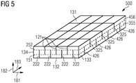
- Fig. 5 shows a cross-sectional view of a permanent magnet 500 comprising three first slits 121, four second slits 222, three fifth slits 325 and four sixth slits 426 according to an exemplary embodiment.
- the three first slits 121 and the four second slits 222 are formed as described in connection with Fig. 1 and Fig. 2 .
- the three fifth slits 325 and the four sixth slits 426 are formed as described in connection with Fig. 3 and Fig. 4 .
- a distance between the first connecting line 151 of the first slits 121 and the second side 132 is equal to a distance between the first connecting line 355 of the fifth slits 325 and the second side 132.
- the distance between the first connecting line 151 of the first slits 121 and the second side 132 may also be equal to or larger than the distance between the first connecting line 355 of the fifth slits 325 and the second side 132 (not shown in Fig. 5 ).
- a distance between the second connecting line 252 of the second slits 222 and the first side 131 is equal to a distance between the second connecting line 456 of the sixth slits 426 and the first side 131.
- each of the four sixth slits 426 squares each of the four second slits 222 and each of the three first slits 121 squares each of the three fifth slits 325. Hence, losses due to the fluctuating magnetic flux are further decreased.
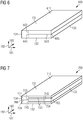
- Fig. 6 shows a cross-sectional view of a permanent magnet 600 comprising one third slit 623 according to an exemplary embodiment.
- the permanent magnet 600 comprises a base body 610 in which one third slit 623 is formed.
- the third slit 623 extends from a third side 133 in the direction of the fourth side 134 and perpendicular to the third side 133. Further, the third slit 623 opens to the third side 133.
- the third slit 623 is formed as a blind hole ending inside the base body 610. As shown in Fig. 6 , the third slit 623 comprises a first end 645 of the third slit 623. The first end 645 of the third slit 623 is a bottom of the blind hole at which the third slit 623 ends inside the base body 610. Additionally, the third slit 623 comprises a second end 665 of the third slit 623 where the third slit 623 opens to the third side 133.
- the third slit 623 has a depth which is identical to a distance between the third side 133 and a first connecting line 653 of the third slit 623 being defined perpendicular to the first side 131 and running through a position in the first direction 181 where the first end 645 of the third slit 623 is.
- the first connecting line 653 of the third slit 623 is distanced to the third side 133 and to the fourth side 134.
- a distance between the fourth side 134 and the first connecting line 653 of the third slit 623 is smaller than a distance between the third side 133 and the first connecting line 653 of the third slit 623.
- the distance between the fourth side 134 and the first connecting line 653 of the third slit 623 may also be equal to or larger than the distance between the third side 133 and the first connecting line 653 of the third slit 623 (not shown in Fig. 6 ). Furthermore, the first connecting line 653 of the third slit 623 is parallel to the third side 133 and the fourth side 134, respectively.
- Fig. 7 shows a cross-sectional view of a permanent magnet 700 comprising two third slits 723 and one fourth slit 724 according to an exemplary embodiment.
- the permanent magnet 700 comprises a base body 710 in which two third slits 723 are formed.
- the two third slits 723 extend parallel to each other from a third side 133 in the direction of the fourth side 134.
- the two third slits 723 are both formed as blind holes ending in the base body 710. As exemplarily shown in Fig. 7 only on one of the two third slits 723, both third slits 723 comprise a first end 745 of the third slit 723. The first end 745 of the third slit 723 is a bottom of the blind hole at which the third slit 723 ends in the base body 710. Additionally, both third slits 723 comprises a second end 765 of the third slit 723 where the third slit 723 opens to the third side 133.
- the two third slits 723 have an identical depth. Hence, the two first ends 745 of the third slits 723 are arranged on a first connecting line 753 of the third slits 723 which is distanced to the fourth side 134 and to the third side 133. A distance between the fourth side 134 and the first connecting line 753 of the third slits 723 is smaller than a distance between the third side 133 and the first connecting line 753 of the third slits 723.
- the distance between the fourth side 134 and the first connecting line 753 of the third slits 723 may also be equal to or larger than a distance between the third side 133 and the first connecting line 753 of the third slits 723 (not shown in Fig. 7 ). Furthermore, the first connecting line 753 of the third slits 723 is parallel to the third side 133 and the fourth side 134, respectively.
- one fourth slit 724 is formed in the base body 710. Seen in the second direction 182 from the second side 132 to the first side 131, there is the first third slit 723, the fourth slit 724 and the second third slit 723. A total distance in the second direction 182 is the length between the first side 131 and the second side 132.
- the fourth slit 724 and the two third slits 723 are formed in the base body 710 such that a distance between the second side 132 and the first fourth slit 724, a distance between the second fourth slit 724 and the first side 131, and a distance between the fourth slit 724 and each of the two third slits 723, are equal.
- the fourth slit 724 is formed as a blind hole in the base body 710. As shown in Fig. 7 , the fourth slit 724 comprises a first end 746 of the fourth slit 724. The first end 746 of the fourth slit 724 is a bottom at which the fourth slit 724 ends in the base body 710. A second connecting line 754 of the fourth slit 724 is perpendicular to the first side 131 and runs through the first end 746 of the fourth slit 724. Additionally, the fourth slit 724 comprises a second end 766 of the fourth slit 724 where the fourth slit 724 opens to the fourth side 134.
- the second connecting line 754 of the fourth slit 724 is distanced to the third side 133 and to the fourth side 134.
- a distance between the third side 133 and the second connecting line 754 of the fourth slit 724 is smaller than a distance between the fourth side 134 and the second connecting line 754 of the fourth slit 724.
- the distance between the third side 133 and the second connecting line 754 of the fourth slit 724 may also be equal to or larger than the distance between the fourth side 134 and the second connecting line 754 of the fourth slit 724 (not shown in Fig. 7 ).
- the second connecting line 754 of the fourth slit 724 is parallel to the first connecting line 753.
- the fourth slit 724 extends in the third direction 183 through the entire base body 710 from the first end surface 111 to a second end surface (not shown in Fig. 7 ) being an opposite surface and equal to the first end surface 111.
- the fourth slit 724 and the two third slits 723 extend parallel to each other and extend such that they never cross each other or are connected in any way.
- Fig. 8 shows a cross-sectional view of a permanent magnet 800 comprising four first slits 821 according to a further exemplary embodiment.
- first slits 821 are formed in the base body 810 such that the four first slits 821 extend from the first side 131 in the direction of the second side 132.
- Each of the first slits 821 have an extension which is angulated to the first side 131.
- Two of the first slits 821 are angulated such that a pointed angle is defined between the first side 131 and the first slit 821 in the direction of the third side 133.
- the other two first slits 821 are angulated such that a pointed angle is defined between the first side 131 and the first slit 821 in the direction of the fourth side 134.
- Each of the first slits 821 is formed as a blind hole ending inside the base body 810. A bottom of each blind hole defines a first end 847 of the first slit 821.
- each first slit 821 comprises a second end 867 of the first slit 821 where the first slit 821 opens to the first side 131.
- the four first slits 821 have an identical depth, hence the four first ends 847 are arranged on a first connecting line 851 of the first slits 821 which is distanced to the first side 131 and the second side 132, respectively.
- the four first slits 821 may have a different length (not shown in Fig. 8 ).
- a distance between the first connecting line 851 of the first slits 821 and the second side 132 is slightly smaller than a distance between the first connecting line 851 of the first slits 821 and the first side 131.
- the distance between the first connecting line 851 of the first slits 821 and the second side 132 may be equal to or larger than the distance between the first connecting line 851 of the first slits 821 and the first side 131 (not shown in Fig. 8 ).
- each of the first slits 821 extends entirely through the base body 810 from a first end surface 111 to a second end surface being the opposite surface and being formed identical and parallel to the first end surface 111.
- Fig. 9 shows a cross-sectional view of a permanent magnet 900 comprising two first slits 921 and two second slits 922 according to a further exemplary embodiment.
- Two first slits 921 and two second slits 922 are formed in the base body 910.
- the two first slits 921 extend from the first side 131 in the direction of the second side 132, and are angulated relatively to the first side 131.
- a pointed angle between the first side 131 and an extension of one of the two first slits 921 is in the direction of the third side 133 and a pointed angle between the first side 131 and an extension of the other one of the two first slits 921 is in the direction of the fourth side 134.
- Each first slit 921 comprises a first end 947 of the first slit 921 which is the bottom of the blind hole forming the first slit 921.
- each of the two first slits 921 comprises a second end 967 of the first slit 921 where the respective first slit 921 opens to the first side 131.
- a distance between the two first ends 947 of the first slit 921 in the first direction 181 is smaller than a distance of the two second ends 967 of the first slit 921 in the first direction 181.
- the distance between the two first ends 947 of the first slit 921 in the first direction 181 may also be equal to or larger than the distance of the two second ends 967 of the first slits 921 in the first direction 181 (not shown in Fig. 9 ).
- two second slits 922 are formed in the base body 910 such that the second slits 922 extend from the second side 132 in the direction of the first side 131 in the second direction 182.
- the extensions of the two second slits 922 are angulated relatively to the second side 132 and are at the same time parallel to the respective other second slit 922.
- Each of the two second slits 922 comprises a first end 948 of the second slit 922 being the bottom of the blind hole at which each second slit 922 ends inside the base body 910, and a second end 968 of the second slit 922 where the second slit 922 opens to the second side 132.
- the two first ends 948 of the second slit 922 are arranged on a second connecting line 952 of the second slits 922 which is parallel to the first connecting line 951 of the first slits 921 and the first side 131.
- a distance between the second connecting line 952 of the second slits 922 and the first side 131 is smaller than a distance between the second connecting line 952 of the second slits 922 and the second side 132 in the second direction 182.
- a first second slit 922 Seen in the first direction 181 between the fourth side 134 and the third side 133, there are arranged a first second slit 922, a first first slit 921, a second second slit 922 and a second first slit 921, adjacent to each other.
- Fig. 10 shows a cross-sectional view of a permanent magnet 1000 comprising five first slits 1001, 1002, 1003, 1004, 1005 according to a further exemplary embodiment.
- first first slit 1001 Seen in the first direction 181 from the fourth side 134 to the third side 133, there is arranged the first first slit 1001, the second first slit 1002, the third first slit 1003, the fourth first slit 1004 and the fifth first slit 1005.
- the first depth of the first first slit 1001 is larger than the second depth of the second first slit 1002, the third depth of the third first slit 1003 and the fourth depth of the fourth first slit 1004, and equal to the fifth depth of the fifth first slit 1005.
- the second depth of the second first slit 1002 is larger than the third depth of the third first slit 1003, and equal to the fourth depth of the fourth first slit 1004.
- a connecting line 1051 connecting the bottom of each of the first slits with each other is shaped as a triangle.
- Fig. 11 shows a cross-sectional view of a permanent magnet 1100 comprising five first slits 1101, 1102, 1103, 1104, 1105 according to a further exemplary embodiment.
- first first slit 1101 Seen in the first direction 181 from the fourth side 134 to the third side 133, there is arranged the first first slit 1101, the second first slit 1102, the third first slit 1103, the fourth first slit 1104 and the fifth first slit 1105.
- the first depth of the first first slit 1101 is equal to the third depth of the third first slit 1103 and the fifth depth of the fifth first slit 1105.
- the second depth of the second first slit 1102 is equal to the fourth depth of the fourth first slit 1104, and smaller than the first depth of the first first slit 1101.
- a connecting line 1151 connecting the bottom of each of the first slits 1101, 1102, 1103, 1104 and 1105 with each other has the shape of a zig-zag line.
- Fig. 12 shows a cross-sectional view of a permanent magnet 1200 comprising six first slits 1201, 1202, 1203, 1204, 1205, 1206 according to a further exemplary embodiment.
- the six first slits 1201, 1202, 1203, 1204, 1205, and 1206 are arranged in an order dependent on their increasing depth. Therefore, the first depth of the first first slit 1201 is smaller than the second depth of the second first slit 1202.
- the second depth of the second first slit 1202 is smaller than the third depth of the third first slit 1203.
- the third depth of the third first slit 1203 is smaller than the fourth depth of the fourth first slit 1204.
- the fourth depth of the fourth first slit 1204 is smaller than the fifth depth of the fifth first slit 1205.
- the fifth depth of the fifth first slit 1205 is smaller than the sixth depth of the sixth first slit 1206.
- a connecting line 1251 connecting the bottom of each of the first slits 1201, 1202, 1203, 1204, 1205, and 1206 with each other has the shape of a straight line having an inclination relatively to the first side 131.
- Fig. 13 shows a cross-sectional view of a permanent magnet 1300 comprising five first slits 1301, 1302, 1303, 1304, 1305 and three second slits 1311, 1312, 1313 according to a further exemplary embodiment.
- a first connecting line 1351 connecting the bottom of each of the first slits 1301, 1302, 1303, 1304, and 1305 with each other has the shape of a straight line having an inclination relatively to the first side 131 and the second side 132, respectively.
- a second connecting line 1352 connecting the bottom of each of the second slits 1311, 1312, and 1313 with each other has the shape of a parabola.
- Fig. 16 shows a cross-sectional view of a permanent magnet 100 comprising three first slits 121 and a divided base body 110 according to an exemplary embodiment.
- the embodiment shown in Fig. 16 is similar to the embodiment shown in Fig. 1 without the separation of the base body 110.
- the base body 110 comprises a first part 1601 comprising the first side 131 and a second part 1602 comprising the second side 132, wherein the first part 1601 has a first mounting surface which is mounted to a second mounting surface of the second part 1602.
- the first part 1601 and the second part 1602 are structurally separated and are fixed together by welding or by gluing.
- a layer 1603 of fixation material, such as glue is provided between the first part1601 and the second part 1602 .
- the first part 1601 and the second part 1602 may be divided such that the first mounting surface and the second mounting surface, respectively is perpendicular to the slits 121. However, in other embodiments, the first mounting surface and the second mounting surface may be angled with respect to the slits 121.
- the embodiment of the base body 110 comprising two parts 1601, 1602 may be applied also to the exemplary embodiment shown in Fig. 2 to Fig. 13 . Additionally, the base body 110 may be also separated in more than two parts 1601, 1602, such that further layers of e.g. glue are provided.
Landscapes
- Engineering & Computer Science (AREA)
- Power Engineering (AREA)
- Physics & Mathematics (AREA)
- Electromagnetism (AREA)
- Manufacturing & Machinery (AREA)
- Permanent Field Magnets Of Synchronous Machinery (AREA)
Abstract
Description
- The present invention relates to the field of reducing eddy current losses in permanent magnets in a permanent magnet machine. Particularly, the present invention relates to a permanent magnet for a permanent magnet machine, it is also called a permanent magnet machine, and a method of manufacturing a permanent magnet for a permanent magnet machine.
- In today's permanent magnet machines in order to reduce eddy current losses in permanent magnets of a permanent magnet machines, normally a magnet element is cut axially and circumferentially into small magnetic pieces which then are polished on all side surfaces. Afterwards, the small magnetic pieces are glued back together in one permanent magnet unit, this is normally called magnet segmentation.
- A current full
permanent magnet element 1401 according to the prior art in a sectional view in the axial direction is shown inFig. 14 together with acover 1404, abaseplate 1403 and aglue layer 1402. The current fullpermanent magnet element 1401 is glued to thebaseplate 1403. Additionally, thecover 1404 is welded to thebaseplate 1403. The current fullpermanent magnet element 1401 is a full block magnet and therefore nothing is reducing the eddy currents generated in the permanent magnet. - For reducing the eddy currents, as shown in
Fig. 15 in a sectional view in the circumferential direction, the current permanent magnet 1500 (shown without the baseplate and the cover) is cut into four smallmagnetic pieces 1501 which are subsequently polished on all surfaces. Thereafter the four smallmagnetic pieces 1501 are glued back together by threeglue layers 1505. Eachglue layer 1505 is arranged between two adjacent smallmagnetic pieces 1501. - While gluing the small
magnetic pieces 1501 together, the smallmagnetic pieces 1501 have to be kept in a fixture (not shown inFig. 14 or Fig. 15 ) to get the desired shape of the finished currentpermanent magnet 1500. The steps of cutting, gluing and handling add extra costs to the final current permanent magnet. - Furthermore, coating the finished current permanent magnet may be difficult as the adhesive property of the surface of the small magnetic pieces and the glue layers are different. This may cause quality problems of the coating.
- The manufacturing costs of a permanent magnet are crucial from the economic perspective of the permanent magnet machine. Further, the reliability of the permanent magnet is a key factor for the operational costs of the permanent magnet machine.
- It may be an objective of the present invention to provide a simple and reliable permanent magnet for a permanent magnet machine which is able to reduce magnet eddy current losses.
- This objective may be solved by the permanent magnet for a permanent magnet machine, the permanent magnet machine and the method of manufacturing the permanent magnet according to the independent claims.
- According to a first aspect of the present invention a permanent magnet for a permanent magnet machine is described. The permanent magnet comprises a base body having a first side and a second side which is an opposite side with respect to the first side. At least one first slit is formed in the base body such that the at least one first slit extends from the first side in the direction of the second side.
- The base body is formed such that the base body comprises a first side and a second side, which are interconnected by a third side and a fourth side as well as a fifth side and a sixth side. The base body is formed monolithically as a one-piece element of a magnetic material. The first side and the second side are distanced from each other, and delimit the base body in one dimension.
- The slit may be formed in the base body by for example multi wire cutting, laser cutting, plasma cutting or autogenous gas cutting.
- The number of necessary first slits may depend on a width of the base body. The width may be the dimension of the base body parallel to the first side and the second side, respectively.
- The first slit extends from the first side in the direction of the second side and may be defined such that the first slit is opened to the first side and extends in the direction of the second side without an opening in the second side. Hence, the first slit may be a blind hole ending inside the base body.
- According to a further aspect of the present invention, a method of manufacturing a permanent magnet for a permanent magnet machine is disclosed. The method comprises providing a base body having a first side and a second side which is an opposite side with respect to the first side, and forming at least one first slit in the base body, such that the at least one first slit extends from the first side in the direction of the second side.
- Advantageously, the above-described permanent magnet may have lower manufacturing costs due to less handling and no necessary gluing process. Omitting the gluing process may have the further advantage that when no glue is used, there is no health risk during handling of the glue. Additionally, there may not be any quality problems with the coating not sticking to the different surfaces of the finished conventional magnet. Further, the lead time is reduced and less production area is needed because of less production steps.
- According to a further exemplary embodiment of the present invention, at least one further first slit is formed in the base body such that the at least one first slit and the at least one further first slit extend parallel to each other.
- The at least one further first slit may be formed by the same method as the at least one first slit. Additionally, the at least one further first slit may extend from the first side in the direction of the second side, and may be distanced from the at least one first slit.
- The at least one further first slit may extend parallel to the at least one first slit. Additionally, the at least one further first slit and the at least one first slit may have the same depth. The depth of the further first slit or the first slit may be measured between a surface position on the first side where the first slit or the further first slit opens to the first side and the bottom of the first slit or the further first slit.
- When the first slit or the further first slit is formed such that the slit extends straight between the surface position of the first side and the bottom, the depth may be defined as the extension of the first slit or the further first slit into the base body. When the first slit or the further first slit extends in a curved way, the depth may be defined as the shortest straight connection between the surface position and the bottom.
- According to a further exemplary embodiment of the present invention, at least one second slit is formed in the base body such that the at least one second slit extends from the second side in the direction of the first side.
- The at least one second slit may be formed by the same method as the at least one first slit. Additionally, the at least one second slit extends opposite to the at least one first slit. Hence, the at least one second slit opens on the opposite side than the at least one first slit, i.e. on the second side instead of on the first side.
- The second slit extends from the second side in the direction of the first side may be defined such that the second slit is opened to the second side and extends in the direction of the first side without an opening in the first side. Hence, the first slit may be a blind hole ending inside the base body.
- The at least one second slit may be formed to extend from the second side in the direction of the first side such that none of the at least one first slits or the at least one further first slits are interconnected with the at least one second slit inside the base body. Hence, none of the slits provided in the base body is formed such that it is a through hole which interconnects two different sides, as for example the first side and the second side.
- According to a further exemplary embodiment of the present invention, the base body is formed such that the at least one first slit and the at least one second slit are arranged alternatingly in a direction which is parallel to the first side.
- Being arranged alternatingly may describe that when the base body is formed with more than one first slit and more than one second slit, one first slit is arranged next to one or two of the second slits. Hence, except of the slits being formed next to the boundaries which interconnect the first side and the second side (seen in a cross-sectional view of the base body), each first slit is arranged between two second slits and each second slit is arranged between two first slits.
- Therefore, for arranging alternatingly, the base body may be formed either with at least one first slit and at least two second slits or with at least one second slit and at least two first slits.
- According to a further exemplary embodiment of the present invention, the base body is formed such that a sum of a depth of the at least one first slit and a depth of the at least one second slit is greater than a distance between the first side and the second side.
- According to an alternative exemplary embodiment of the present invention, the base body is formed such that a sum of a depth of the at least one first slit and a depth of the at least one second slit is equal or smaller than a distance between the first side and the second side.
- The depth of the at least one first slit may be defined depending on whether the first slit extends perpendicular to the first side/second side or angulated and not perpendicular to the first side/second side.
- Additionally, the depth of the at least one first slit may be defined dependent on the strength of the magnetic field generated in the base body.
- On the one hand, when the first slit extends perpendicular to the first side, the depth may be defined as a distance between an opening of the first slit on the first side and the bottom of the first slit inside the base body. Accordingly, when the second slit extends perpendicular to the second side, the depth may be defined as a distance between an opening of the second slit on the second side and the bottom of the second slit inside the base body.
- On the other hand, when the first slit extends angulated and not perpendicular with respect to the first side, the depth may be defined as a distance between the bottom of the first slit inside the base body and the first side measured perpendicular to the first side. Accordingly, when the second slit extends angulated and not perpendicular to the second side, the depth may be defined as a distance between the bottom of the second slit inside the base body and the second side measured perpendicular to the second side.
- Therefore, when there are formed more than one first slit in the base body, each of the first slits may have a different depth. Furthermore, when there are formed more than one second slit in the base body, each of the second slits may have a different depth.
- The depth of one first slit and the depth of one adjacent second slit may be added to a respective sum which may be compared to the distance between the first side and the second side. When there is an uneven total number of first slits and second slits, always a first slit and an adjacent second slit may form the sum, even though one of the first slits or one of the second slits is added to two different sums.
- Hence, one of the at least one first slit and one of the at least one second slit may form a pair of slits. The first slit and the second slit of the pair of slits are distanced from each other in a first direction being parallel to the first side. A middle position may be defined as the position which is in the geometrical middle in the first direction between the first slit and the second slit of the pair of slits. Further, the distance between the first side and the second side may be measured at the middle position, and is the distance between the first side and the second side in a second direction being perpendicular to the first direction.
- Therefore, seen in the second direction in a cross section having a normal being parallel to a third direction which is perpendicular to the first direction and the second direction, an extension of the first slit and an extension of the second slit overlap in the second direction.
- As each of the at least one first slit and each of the at least one second slit may have a different depth in the second direction, a connecting line interconnecting the bottom point of each slit, may be formed as a zig-zag line.
- According to a further exemplary embodiment of the present invention, the base body is formed such that the at least one first slit and/or the at least one second slit have the same depth in a direction extending from the first side to the second side.
- According to an alternative exemplary embodiment of the present invention, the base body is formed such that the at least one first slit and the at least one second slit have different depths in a direction extending from the first side to the second side.
- A different depth of the at least one first slit and the at least one second slit may be advantageous when the magnetic field generated near the first side and the magnetic field generated near the second side are of different strengths.
- When the at least one first slit and the at least one second slit have the same depth in the direction extending from the first side to the second side, i.e. in the second direction as defined above, the bottom of each first slit is arranged on a first connecting line which is parallel to the first side. Correspondingly, the bottom of each second slit is arranged on a second connecting line which is parallel to the second side. The first connecting line is distanced from the second connecting line as the sum of the depth of the first slit and the depth of the second slit is greater than the distance between the first side and the second side as described in detail above.
- At the same time, a distance between the first connecting line and the second side is smaller than a distance between the first connecting line and the first side. Accordingly, a distance between the second connecting line and the first side is smaller than a distance between the second connecting line and the second side as the sum of the depth of the first slit and the depth of the second slit is greater than the distance between the first side and the second side as described in detail above.
- According to a further exemplary embodiment of the present invention, the base body is formed such that the at least one first slit extends perpendicular to the first side.
- The at least one first slit extends parallel to the first side in the present application may be defined such that an extension of the shortest connection between the surface position where the first slit opens to the first side and the bottom of the first slit extends perpendicular to the curvature of the first side at the surface position where the first slit opens to the first side.
- In a further exemplary embodiment, the base body may be formed such that the at least one second slit extends perpendicular to the second side.
- Correspondingly, the at least one second slit extends perpendicular to the second side in the present application may be defined such that an extension of the shortest connection between the surface position where the second slit opens to the second side and the bottom of the second slit extends perpendicular to the curvature of the second side at the surface position where the second slit opens to the second side.
- According to a further exemplary embodiment of the present invention, the base body is formed such that an angle is formed between the at least one first slit and the first side, and the angle is in the range of 0° and to 180°, particularly 45° to 135°.
- In an exemplary embodiment, an extension of the first slit begins on the first side at a surface position where the first slit opens to the first side. At this surface position a tangent is applied on the contour of the curvature of the first side. In this exemplary embodiment, the first slit extends from the first side in the direction of the second side without any curvatures. Further, the first slit is a blind hole ending inside the base body and hence comprises a bottom. A connection line is defined from the surface position on the first side to the bottom. Between the connection line and the tangent an angle is defined, which is in the range of larger than 0° and smaller than 180°, i.e. 45° to 135°, particularly in the range of 65° to 115°, more particularly 90°.
- In a further exemplary embodiment, the first slit extends from the first side in the direction of the second side in a curved way. In this embodiment, the connection line between the bottom and the surface position on the first side where the first slit cuts the first side, is the shortest connection between the two points. Analogously to the definition above, an angle is defined between the connection line and the tangent, which is in the range of 0° to 180°, i.e. 45° to 135°, particularly in the range of 65° to 115°, more particularly 90°.
- Correspondingly, an extension of the second slit begins on the second side at a surface position where the second slit opens to the second side. At this surface position a tangent is applied on the contour of the curvature of the second side. In this exemplary embodiment, the second slit extends from the second side in the direction of the first side without any curvatures. Further, the second slit is a blind hole ending inside the base body and hence comprises a bottom. A connection line is defined from the surface position on the second side to the bottom. Between the connection line and the tangent an angle is defined, which is in the range of larger than 0° and smaller than 180°, i.e. 45° to 135°, particularly in the range of 65° to 115°, more particularly 90°.
- According to a further exemplary embodiment of the present invention, the base body is formed such that the at least one first slit extends from the first side in the direction of the second side more than at least 1%, particularly at least 25%, more particularly more than 50%, even more particularly more than 80% of a distance between the first side and the second side.
- The first slit extends from the first side in the direction of the second side more than 1% of the distance between the first side and the second side. The maximum depth of the slit may be limited by a minimal mechanical strength requirement, i.e. the minimal mechanical strength requirement to keep the necessary strength of the magnet. Therefore, the base body is still be held together without the need of additional glue.
- The surface position on the first side where the first slit opens to the first side may be a first point. The first slit is formed as a blind hole in the base body, and the bottom of the blind hole may be a second point. A connection line between the first point and the second point may be defined as the shortest connection between the first point and the second point. The connection line may be virtually elongated such that a virtual cutting point of the connection line and the second side may be defined as a third point. Hence, the distance between the first side and the second side may be defined as the length between the first point and the third point.
- According to a further exemplary embodiment, the first slit extends from the first side in the direction of the second side of for example 90% of the distance between the first side and the second side. Hence, on the first hand, the base body may still be held together by the 10% none-cut material of the base body and may be easily handled. On the other hand, the base body may be cut in the part in which the magnetic flux fluctuates the most.
- Correspondingly, in a further exemplary embodiment, the base body may be formed such that the at least one second slit extends from the second side in the direction of the first side more than at least for example 90% of a distance between the second side and the first side.
- Hence, by additionally providing the second slit, the 10% of the material which is not cut by the first slit may be cut instead by the second slit and at the same time due to the second slit being distanced to the first slit in the direction which is perpendicular to the first side, the base body is still be held together without the need of additional glue.
- According to a further exemplary embodiment of the present invention, the at least one first slit is formed in the base body such that in a cross-section view of the base body the at least one first slit has a straight, saw-toothed and/or undulated shape.
- The cross-section view may be defined as the sectional representation in which the first side and the second side are shown as a respective boundary line. Additionally, the first side and the second side are interconnected by the third side and the fourth side which in the cross-section view are also shown as a respective boundary line.
- On the one hand, forming the first slit in the base body with a straight shape may have the advantage that the first slit may be easily formed by for example wire cutting, with little complexity for the equipment.
- On the other hand, forming the first slit in the base body with an undulated shape may have the advantage that the absolute depth of the first slit inside the base body may be elongated compared to the depth of a straight shaped first slit.
- Forming the first slit in the base body with a saw-toothed shape may be advantageously in view of the manufacturing and the elongated absolute depth, because the saw-toothed shape may be easily cut in the base body as the direction between two directions of the saw-toothed shape may be easily manufactured. At the same time the absolute depth of the saw-toothed shape is elongated compared to the depth of the straight shape.
- According to a further exemplary embodiment of the present invention, the base body further comprises a third side and a fourth side which is an opposite side with respect to the third side, and the third side and the fourth side interconnect the first side and the second side. Further, at least one third slit is formed in the base body such that the at least one third slit extends from the third side in the direction of the fourth side.
- The at least one third slit may be formed by the same method as the at least one first slit and/or the second slit. Additionally, the third slit may have the same shape as the first slit and/or the second slit.
- The third slit extends from the third side in the direction of the fourth side may be defined such that the third slit is opened to the third side and extends in the direction of the fourth side without an opening in the fourth side. Hence, the third slit may be formed as a blind hole as defined above with respect to the first slit and/or the second slit.
- An extension of the third slit and an extension of the first slit and an extension of the second slit, respectively, may not cut each other inside the base body because then a portion of the base body may no longer be connected with the remains of the base body.
- Advantageously, the at least one third slit may prevent magnetic flux fluctuations which are not parallel to the first side but rather parallel to the third side, from propagating through the base body.
- According to a further exemplary embodiment of the present invention, the at least one fourth slit is formed in the base body such that the at least one fourth slit extends from the fourth side in the direction of the third side.
- The at least one fourth slit may be formed by the same method as the at least one third slit.
- The fourth slit extends from the fourth side in the direction of the third side may be defined such that the fourth slit is opened to the fourth side and extends in the direction of the third side without an opening in the third side. Hence, the fourth slit may be formed as a blind hole as defined above with respect to the first slit and/or the second slit.
- The at least one fourth slit and the at least one third slit may be formed to extend between the fourth side and the third side such that none of the at least one first slit and the at least one second slit is interconnected with the at least one fourth slit or the at least one third slit. Hence, none of the slits provided in the base body is formed such that it is a through hole connecting two different sides with each other.
- According to a further exemplary embodiment of the present invention, the base body is formed such that the at least one third slit and/or the at least one fourth slit have the same depth in a direction extending from the third side to the fourth side.
- When the at least one third slit and the at least one fourth slit have the same depth in the direction extending from the third side to the fourth side, i.e. in the first direction as defined above, the bottom of each third slit is arranged on a third connecting line which is parallel to the first side. Correspondingly, the bottom of each fourth slit is arranged on a fourth connecting line which is parallel to the second side. The third connecting line is distanced from the fourth connecting line as the sum of the depth of the third slit and the depth of the fourth slit is greater than the distance between the third side and the fourth side as described in detail above with reference to the first slit and the second slit.
- At the same time, a distance between the third connecting line and the fourth side is smaller than a distance between the third connecting line and the third side. Accordingly, a distance between the fourth connecting line and the third side is smaller than a distance between the fourth connecting line and the fourth side as the sum of the depth of the third slit and the depth of the fourth slit is greater than the distance between the third side and the fourth side as described in detail above with reference to the first slit and the second slit.
- According to an alternative embodiment of the invention, the base body is formed such that the at least one third slit and/or the at least one fourth slit have different depths in a direction extending from the third side to the fourth side.
- A different depth of the at least one third slit and the at least one fourth slit may be advantageous when the magnetic field generated near the third side and the magnetic field generated near the fourth side are of different strengths.
- According to a further exemplary embodiment of the present invention, a first direction is parallel to the first side, a second side is an opposite side with respect to the first side, and a third side and a fourth side interconnect the first side and the second side. Further, a second direction is parallel to the third side, and a third direction is perpendicular to the first direction and the second direction. Additionally, the at least one first slit extends entirely through the base body in the third direction.
- The base body is formed such that the at least one first slit extends from one end face to another opposing end face being parallel to the one end face. Additionally, the base body is formed such that the at least one second slit extends entirely through the base body from the one end face to the other end face.
- Furthermore, the base body is formed such that the at least one third slit and the at least one fourth slit extends entirely through the base body in the third direction.
- According to a further aspect of the present invention, a permanent magnet machine is disclosed. The permanent magnet machine comprises a permanent magnet as described above, and a component which generates a magnetic field.
- The component generating a magnetic field may particularly be an electromagnetic coil.
- The permanent magnet may be arranged such that a first side being parallel to the first direction, is parallel to the magnetic field lines generated by the permanent magnet machine. Preferably, the at least one first slit and the at least one second slit, respectively, extends perpendicular to the generated magnetic field lines.
- According to a further exemplary embodiment of the present invention, the permanent magnet is arranged in the permanent magnet machine such that the magnetic field is providable perpendicular to an extension of the at least one first slit.
- Hence, the magnetic flux fluctuations which may propagate parallel to the magnetic field lines are interrupted by the at least one first slit.
- The number of first slits may depend on the size of the magnet and the frequency of the fluctuating magnetic flux. According to a further exemplary embodiment of the present invention, a distance between adjacent slits depends on the strength of the fluctuating magnetic field.
- Hence, advantageously, the number of first slits, second slits, third slits and fourth slits may depend on the size of the magnet and the frequency of the fluctuating magnetic flux. Furthermore, the orientation and the depth of the first slits, the second slits, the third slits and the fourth slits may be adapted on the strength of the magnetic field.
- According to a further exemplary embodiment of the invention, at least one of the first side, the second side, the third side or the fourth side is shaped.
- Being shaped means that the respective side seen in the cross-sectional view, is not a straight line but rather has any shape, as for example rounded, zig-zig or an arbitrary geometrical shape.
- According to a further exemplary embodiment of the permanent magnet, the base body comprises a first part comprising the first side and a second part comprising the second side, wherein the first part has a first mounting surface which is mounted to a second mounting surface of the second part. The first part and the second part are structurally separated and are fixed together by welding or by gluing as described below. In particular, between the first part and the second part a layer of fixation material, such as glue, may be provided. Hence, by providing an additional layer between the first part and the second part, the reduction of eddy current losses becomes more effective.
- According to a further exemplary embodiment of the permanent magnet between the first mounting surface and the second mounting surface a glue layer is arranged for gluing the first part and the second part together. As described above, because of the gluing layer between the first part and the second part, the reduction of eddy current losses becomes more effective.
- According to a further exemplary embodiment of the method, the base body comprises a first part comprising the first side and a second part comprising the second side, wherein the first part has a first mounting surface which is mounted to a second mounting surface of the second part. Before the step of forming the at least one first slit the method comprises gluing the first mounting surface and the second mounting surface together for forming the base body and for providing a glue layer between the first part and the second part.
- Hence, the reduction of eddy current losses becomes more effective and thereby losses are lower leading to a lower mecca temperature and the higher performance and efficiency. Specifically, by making the base body in two separate parts (layers) the benefit of splitting is maximised as the eddy currents cannot flow between the lower first part and the upper second part. The gluing of one part (layer) is much more cost-effective than making the magnet in small pieces by slitting and there after gluing the small pieces together.
- It has to be noted that embodiments of the invention have been described with reference to different subject-matters. In particular, some embodiments have been described with reference to apparatus type claims whereas other embodiments have been described with reference to method type claims. However, a person skilled in the art will gather from the above and the following description that, unless otherwise notified, in addition to any combination of features belonging to one type of subject-matter also any combination between features relating to different subject-matters, in particular between features of the apparatus type claims and features of the method type claims is considered as to be disclosed with this application.
- The aspects defined above and further aspects of the present invention are apparent from the examples of embodiment to be described hereinafter and are explained with reference to the examples of embodiment. The invention will be described in more detail hereinafter with reference to examples of embodiment but to which the invention is not limited.
-
Fig. 1 shows a cross-sectional view of a permanent magnet comprising three first slits according to an exemplary embodiment. -
Fig. 2 shows a cross-sectional view of a permanent magnet comprising three first slits and four second slits according to an exemplary embodiment. -
Fig. 3 shows a cross-sectional view of a permanent magnet comprising three fifth slits according to an exemplary embodiment. -
Fig. 4 shows a cross-sectional view of a permanent magnet comprising three fifth slits and four sixth slits according to an exemplary embodiment. -
Fig. 5 shows a cross-sectional view of a permanent magnet comprising three first slits, four second slits, three fifth slits and four sixth slits according to an exemplary embodiment. -
Fig. 6 shows a cross-sectional view of a permanent magnet comprising one third slit according to an exemplary embodiment. -
Fig. 7 shows a cross-sectional view of a permanent magnet comprising two third slits and one fourth slit according to an exemplary embodiment. -
Fig. 8 shows a cross-sectional view of a permanent magnet comprising four first slits according to a further exemplary embodiment. -
Fig. 9 shows a cross-sectional view of a permanent magnet comprising two first slits and two second slits according to a further exemplary embodiment. -
Fig. 10 shows a cross-sectional view of a permanent magnet comprising five first slits according to an exemplary embodiment. -
Fig. 11 shows a cross-sectional view of a permanent magnet comprising five first slits according to a further exemplary embodiment. -
Fig. 12 shows a cross-sectional view of a permanent magnet comprising six first slits according to an exemplary embodiment. -
Fig. 13 shows a cross-sectional view of a permanent magnet comprising five first slits and three second slits according to an exemplary embodiment. -
Fig. 14 shows a sectional view in the axial direction of a current full permanent magnet element according to the prior art. -
Fig. 15 shows a sectional view in the circumferential direction of a current full permanent magnet element according to the prior art. -
Fig. 16 shows a cross-sectional view of a permanent magnet comprising three first slits and a divided base body according to an exemplary embodiment. - The illustrations in the drawings are schematically. It is noted that in different figures, similar or identical elements are provided with the same reference signs.
-
Fig. 1 shows a cross-sectional view of apermanent magnet 100 comprising threefirst slits 121 according to an exemplary embodiment. - The
permanent magnet 100 comprises abase body 110 in which threefirst slits 121 are formed. The threefirst slits 121 extend parallel to each other from afirst side 131 in the direction of asecond side 132. Further, thesecond side 132 is an opposite side of thefirst side 131 and is distanced from thefirst side 131 in asecond direction 182, and is interconnected with thefirst side 131 by athird side 133 and afourth side 134, respectively. - The
base body 110 comprises afirst end face 111 which is shown inFig. 1 and a second end face (not shown inFig. 1 ) distanced from thefirst end face 111 in athird direction 183 and being identical and parallel to thefirst end face 111. - The three
first slits 121 are each formed as blind holes ending in thebase body 110. As exemplarily shown inFig. 1 only on onefirst slit 121, each of the threefirst slits 121 comprises afirst end 141 of thefirst slit 121. Thefirst end 141 of thefirst slit 121 is a bottom of the blind hole at which thefirst slit 121 ends inside thebase body 110. Additionally, each of the threefirst slits 121 comprises asecond end 161 of thefirst slit 121 where thefirst slit 121 opens to thefirst side 131. - In the exemplary embodiment shown in
Fig. 1 , the threefirst slits 121 have an identical depth. However, the first slits may have a different length as may be seen inFigures 10 to 13 . Hence, the threefirst ends 141 of thefirst slit 121 are arranged on a first connectingline 151 of thefirst slits 121 which is distanced to thefirst side 131 and to thesecond side 132. In this exemplarily embodiment, a distance between thesecond side 132 and the first connectingline 151 of thefirst slits 121 is smaller than a distance between thefirst side 131 and the first connectingline 151 of thefirst slits 121. However, it may be understood that a distance between thesecond side 132 and the first connectingline 151 of thefirst slits 121 could be equal or larger than a distance between thefirst side 131 and the first connectingline 151 of the first slits 121 (not shown inFig. 1 ). Furthermore, the first connectingline 151 of thefirst slits 121 is parallel to thefirst side 131 and thesecond side 132, respectively. -
Fig. 2 shows a cross-sectional view of thepermanent magnet 200 comprising threefirst slits 121 and foursecond slits 222 according to an exemplary embodiment. - The
base body 110 is formed with foursecond slits 222. Seen in thefirst direction 181 from thefourth side 134 to thethird side 133, there is a firstsecond slit 222, a firstfirst slit 121, a secondsecond slit 222, a secondfirst slit 121, a thirdsecond slit 222, a thirdfirst slit 121 and a fourthsecond slit 222. A total distance in thefirst direction 181 is the length between thefourth side 134 and thethird side 133. The foursecond slits 222 and the threefirst slits 121 are formed in thebase body 210 such that a distance between thefourth side 134 and the firstsecond slit 222, a distance between the fourthsecond slit 222 and thethird side 133, and a distance between asecond slit 222 and an adjacentfirst slit 121, are equal. - The three
first slits 121 are formed identical to the three first slits inFig. 1 . The foursecond slits 222 are each formed as blind holes ending inside thebase body 210. As exemplarily shown inFig. 2 only on onesecond slit 222, each of the foursecond slits 222 comprises afirst end 242 of thesecond slit 222. Thefirst end 242 of thesecond slit 222 is a bottom of the blind hole at which thesecond slit 121 ends in thebase body 210. Additionally, each of the foursecond slits 222 comprises asecond end 262 of thesecond slit 222 where thesecond slit 222 opens to thesecond side 132. - The four
second slits 222 have an identical depth. However, the second slits may have a different length as shown inFig. 13 . Hence, the foursecond ends 242 of thesecond slits 222 are arranged on a second connectingline 252 of thesecond slits 222 which is distanced to thefirst side 131 and to thesecond side 132. In this exemplarily embodiment, a distance between thefirst side 131 and the second connectingline 252 of thesecond slits 222 is smaller than a distance between thesecond side 132 and the second connectingline 252 of thesecond slits 222. However, it may be understood that a distance between thesecond side 132 and the first connectingline 151 of thefirst slits 121 could be equal or larger than a distance between thefirst side 131 and the first connectingline 151 of the first slits 121 (not shown inFig. 2 ). Furthermore, the second connectingline 252 of thesecond slits 222 is parallel to thefirst side 131 and thesecond side 132, respectively. - Each of the four
second slits 222 extends in thethird direction 183 through theentire base body 210 from thefirst end surface 111 to a second end surface (not shown inFig. 2 ) being an opposite surface and equal to thefirst end surface 111. - The three
first slits 121 and the foursecond slits 222 extend parallel to each other and extend such that they never cross each other or are connected in any way. -
Fig. 3 shows a cross-sectional view of apermanent magnet 300 comprising threefifth slits 325 according to an exemplary embodiment. - The
base body 310 is formed with threefifth slits 325 each extending from thethird side 133 to thefourth side 134 such that the threefifth slits 325 are opened to thefirst side 131. - The three
fifth slits 325 are each formed as blind holes in thebase body 310. As exemplarily shown inFig. 3 only on onefifth slit 325, each of the threefifth slits 325 comprises afirst end 343 of thefifth slit 325. Thefirst end 343 of thefifth slit 325 is a bottom of the blind hole at which thefifth slit 325 ends inside thebase body 310. Additionally, each of the threefifth slits 325 comprises asecond end 363 of thefifth slit 325 where thefifth slit 325 opens to thefirst side 131. - The three
fifth slits 325 have an identical depth. However, the third slits may have a different depth (not shown inFig. 3 ). Hence, the threesecond ends 343 of thefifth slits 325 are arranged on a first connectingline 355 of thefifth slits 325 which is distanced to thesecond side 132 and to thefirst side 131. A distance between thesecond side 132 and the first connectingline 355 of thefifth slits 325 is smaller than a distance between thefirst side 131 and the first connectingline 355 of thefifth slits 325. However, it may be understood that a distance between thesecond side 132 and the first connectingline 355 of thefifth slits 325 could also be equal or larger than a distance between thefirst side 131 and the first connectingline 355 of the fifth slits 325 (not shown inFig. 3 ). - Each of the three
fifth slits 325 extends entirely through thebase body 310 from thethird side 133 to thefourth side 134. -
Fig. 4 shows a cross-sectional view of apermanent magnet 400 comprising threefifth slits 325 and foursixth slits 426 according to an exemplary embodiment. - The
base body 410 is formed with threefifth slits 325 and foursixth slits 426. Seen in thethird direction 183 from thefirst end surface 111 to the second end surface, there is a firstsixth slit 426, a firstfifth slit 325, a secondsixth slit 426, a secondfifth slit 325, a thirdsixth slit 426, a thirdfifth slit 325 and a fourthsixth slit 426. A total distance in thethird direction 183 is the length between thefirst end surface 111 and the second end surface being parallel to thefirst end surface 111. The foursixth slits 426 and the threefifth slits 325 are formed in thebase body 410 such that a distance between thefirst end surface 111 and the firstsixth slit 426, a distance between the fourthsixth slit 426 and the second end surface, and a distance between asixth slit 426 and an adjacentfifth slit 325, are equal. However, the distance between the fourthsixth slit 426 and the second end surface, and a distance between asixth slit 426 and an adjacentfifth slit 325 may be different (not shown inFig. 4 ). - The three
fifth slits 325 and the foursixth slits 426 are each formed as respective blind holes in thebase body 410. As exemplarily shown inFig. 4 only on onesixth slit 426, each of the foursixth slits 426 comprises afirst end 444 of thesixth slit 426. Thefirst end 444 of thesixth slit 426 is a bottom of the blind hole at which thesixth slit 426 ends inside thebase body 410. Additionally, each of the foursixth slits 426 comprises asecond end 464 of thesixth slit 426 where thesixth slit 426 opens to thefirst side 131. - The four
sixth slits 426 have an identical depth. Hence, the foursecond ends 444 of thesixth slits 426 are arranged on a second connectingline 456 of thesixth slits 426 which is distanced to thefirst side 131 and to thesecond side 132. A distance between thefirst side 131 and the second connectingline 456 of thesixth slits 426 is smaller than a distance between thesecond side 132 and the second connectingline 456 of thesixth slits 426. However, the distance between thefirst side 131 and the second connectingline 456 of thesixth slits 426 may also be identical or larger than the distance between thesecond side 132 and the second connectingline 456 of the sixth slits 426 (not shown inFig. 4 ). Furthermore, the second connectingline 456 of thesixth slits 426 is parallel to thefirst side 131 and thesecond side 132, respectively. Additionally, seen in thesecond direction 182 from thesecond side 132 to thefirst side 131, there is thesecond side 132, the first connectingline 355 of thefifth slits 325, the second connectingline 456 of thesixth slits 426 and thefirst side 131, each extending parallel to each other. - Each of the four
sixth slits 426 extends in thefirst direction 181 through theentire base body 410 from thethird side 133 to thefourth side 134 being an opposite surface and equal to thethird side 133. - The three
fifth slits 325 and the foursixth slits 426 extend parallel to each other and extend such that they never cross each other or are connected in any way. -
Fig. 5 shows a cross-sectional view of apermanent magnet 500 comprising threefirst slits 121, foursecond slits 222, threefifth slits 325 and foursixth slits 426 according to an exemplary embodiment. - The three
first slits 121 and the foursecond slits 222 are formed as described in connection withFig. 1 and Fig. 2 . The threefifth slits 325 and the foursixth slits 426 are formed as described in connection withFig. 3 and Fig. 4 . - A distance between the first connecting
line 151 of thefirst slits 121 and thesecond side 132 is equal to a distance between the first connectingline 355 of thefifth slits 325 and thesecond side 132. However, it may be understood that the distance between the first connectingline 151 of thefirst slits 121 and thesecond side 132 may also be equal to or larger than the distance between the first connectingline 355 of thefifth slits 325 and the second side 132 (not shown inFig. 5 ). Correspondingly, a distance between the second connectingline 252 of thesecond slits 222 and thefirst side 131 is equal to a distance between the second connectingline 456 of thesixth slits 426 and thefirst side 131. - Further, each of the four
sixth slits 426 squares each of the foursecond slits 222 and each of the threefirst slits 121 squares each of the threefifth slits 325. Hence, losses due to the fluctuating magnetic flux are further decreased. -
Fig. 6 shows a cross-sectional view of apermanent magnet 600 comprising onethird slit 623 according to an exemplary embodiment. - The
permanent magnet 600 comprises abase body 610 in which onethird slit 623 is formed. Thethird slit 623 extends from athird side 133 in the direction of thefourth side 134 and perpendicular to thethird side 133. Further, thethird slit 623 opens to thethird side 133. - The
third slit 623 is formed as a blind hole ending inside thebase body 610. As shown inFig. 6 , thethird slit 623 comprises afirst end 645 of thethird slit 623. Thefirst end 645 of thethird slit 623 is a bottom of the blind hole at which thethird slit 623 ends inside thebase body 610. Additionally, thethird slit 623 comprises asecond end 665 of thethird slit 623 where thethird slit 623 opens to thethird side 133. - The
third slit 623 has a depth which is identical to a distance between thethird side 133 and a first connectingline 653 of thethird slit 623 being defined perpendicular to thefirst side 131 and running through a position in thefirst direction 181 where thefirst end 645 of thethird slit 623 is. The first connectingline 653 of thethird slit 623 is distanced to thethird side 133 and to thefourth side 134. A distance between thefourth side 134 and the first connectingline 653 of thethird slit 623 is smaller than a distance between thethird side 133 and the first connectingline 653 of thethird slit 623. However, it may be understood that the distance between thefourth side 134 and the first connectingline 653 of thethird slit 623 may also be equal to or larger than the distance between thethird side 133 and the first connectingline 653 of the third slit 623 (not shown inFig. 6 ). Furthermore, the first connectingline 653 of thethird slit 623 is parallel to thethird side 133 and thefourth side 134, respectively. -
Fig. 7 shows a cross-sectional view of apermanent magnet 700 comprising twothird slits 723 and onefourth slit 724 according to an exemplary embodiment. - The
permanent magnet 700 comprises abase body 710 in which twothird slits 723 are formed. The twothird slits 723 extend parallel to each other from athird side 133 in the direction of thefourth side 134. - The two
third slits 723 are both formed as blind holes ending in thebase body 710. As exemplarily shown inFig. 7 only on one of the twothird slits 723, boththird slits 723 comprise afirst end 745 of thethird slit 723. Thefirst end 745 of thethird slit 723 is a bottom of the blind hole at which thethird slit 723 ends in thebase body 710. Additionally, boththird slits 723 comprises asecond end 765 of thethird slit 723 where thethird slit 723 opens to thethird side 133. - The two
third slits 723 have an identical depth. Hence, the twofirst ends 745 of thethird slits 723 are arranged on a first connectingline 753 of thethird slits 723 which is distanced to thefourth side 134 and to thethird side 133. A distance between thefourth side 134 and the first connectingline 753 of thethird slits 723 is smaller than a distance between thethird side 133 and the first connectingline 753 of thethird slits 723. However, it may be understood that the distance between thefourth side 134 and the first connectingline 753 of thethird slits 723 may also be equal to or larger than a distance between thethird side 133 and the first connectingline 753 of the third slits 723 (not shown inFig. 7 ). Furthermore, the first connectingline 753 of thethird slits 723 is parallel to thethird side 133 and thefourth side 134, respectively. - Additionally, one
fourth slit 724 is formed in thebase body 710. Seen in thesecond direction 182 from thesecond side 132 to thefirst side 131, there is the firstthird slit 723, thefourth slit 724 and the secondthird slit 723. A total distance in thesecond direction 182 is the length between thefirst side 131 and thesecond side 132. Thefourth slit 724 and the twothird slits 723 are formed in thebase body 710 such that a distance between thesecond side 132 and the firstfourth slit 724, a distance between the secondfourth slit 724 and thefirst side 131, and a distance between thefourth slit 724 and each of the twothird slits 723, are equal. - The
fourth slit 724 is formed as a blind hole in thebase body 710. As shown inFig. 7 , thefourth slit 724 comprises afirst end 746 of thefourth slit 724. Thefirst end 746 of thefourth slit 724 is a bottom at which thefourth slit 724 ends in thebase body 710. A second connectingline 754 of thefourth slit 724 is perpendicular to thefirst side 131 and runs through thefirst end 746 of thefourth slit 724. Additionally, thefourth slit 724 comprises asecond end 766 of thefourth slit 724 where thefourth slit 724 opens to thefourth side 134. Additionally, the second connectingline 754 of thefourth slit 724 is distanced to thethird side 133 and to thefourth side 134. A distance between thethird side 133 and the second connectingline 754 of thefourth slit 724 is smaller than a distance between thefourth side 134 and the second connectingline 754 of thefourth slit 724. However, it may be understood that the distance between thethird side 133 and the second connectingline 754 of thefourth slit 724 may also be equal to or larger than the distance between thefourth side 134 and the second connectingline 754 of the fourth slit 724 (not shown inFig. 7 ). Furthermore, the second connectingline 754 of thefourth slit 724 is parallel to the first connectingline 753. - The
fourth slit 724 extends in thethird direction 183 through theentire base body 710 from thefirst end surface 111 to a second end surface (not shown inFig. 7 ) being an opposite surface and equal to thefirst end surface 111. - The
fourth slit 724 and the twothird slits 723 extend parallel to each other and extend such that they never cross each other or are connected in any way. -
Fig. 8 shows a cross-sectional view of apermanent magnet 800 comprising fourfirst slits 821 according to a further exemplary embodiment. - Four
first slits 821 are formed in thebase body 810 such that the fourfirst slits 821 extend from thefirst side 131 in the direction of thesecond side 132. Each of thefirst slits 821 have an extension which is angulated to thefirst side 131. Two of thefirst slits 821 are angulated such that a pointed angle is defined between thefirst side 131 and thefirst slit 821 in the direction of thethird side 133. The other twofirst slits 821 are angulated such that a pointed angle is defined between thefirst side 131 and thefirst slit 821 in the direction of thefourth side 134. Each of thefirst slits 821 is formed as a blind hole ending inside thebase body 810. A bottom of each blind hole defines afirst end 847 of thefirst slit 821. Additionally, eachfirst slit 821 comprises asecond end 867 of thefirst slit 821 where thefirst slit 821 opens to thefirst side 131. - Furthermore, the four
first slits 821 have an identical depth, hence the fourfirst ends 847 are arranged on a first connectingline 851 of thefirst slits 821 which is distanced to thefirst side 131 and thesecond side 132, respectively. However, it may be understood that the fourfirst slits 821 may have a different length (not shown inFig. 8 ). A distance between the first connectingline 851 of thefirst slits 821 and thesecond side 132 is slightly smaller than a distance between the first connectingline 851 of thefirst slits 821 and thefirst side 131. However, it may be understood that the distance between the first connectingline 851 of thefirst slits 821 and thesecond side 132 may be equal to or larger than the distance between the first connectingline 851 of thefirst slits 821 and the first side 131 (not shown inFig. 8 ). - Additionally, each of the
first slits 821 extends entirely through thebase body 810 from afirst end surface 111 to a second end surface being the opposite surface and being formed identical and parallel to thefirst end surface 111. -
Fig. 9 shows a cross-sectional view of apermanent magnet 900 comprising twofirst slits 921 and twosecond slits 922 according to a further exemplary embodiment. - Two
first slits 921 and twosecond slits 922 are formed in thebase body 910. The twofirst slits 921 extend from thefirst side 131 in the direction of thesecond side 132, and are angulated relatively to thefirst side 131. A pointed angle between thefirst side 131 and an extension of one of the twofirst slits 921 is in the direction of thethird side 133 and a pointed angle between thefirst side 131 and an extension of the other one of the twofirst slits 921 is in the direction of thefourth side 134. Eachfirst slit 921 comprises afirst end 947 of thefirst slit 921 which is the bottom of the blind hole forming thefirst slit 921. Additionally, each of the twofirst slits 921 comprises asecond end 967 of thefirst slit 921 where the respectivefirst slit 921 opens to thefirst side 131. Hence, a distance between the twofirst ends 947 of thefirst slit 921 in thefirst direction 181 is smaller than a distance of the twosecond ends 967 of thefirst slit 921 in thefirst direction 181. However, it may be understood, that the distance between the twofirst ends 947 of thefirst slit 921 in thefirst direction 181 may also be equal to or larger than the distance of the twosecond ends 967 of thefirst slits 921 in the first direction 181 (not shown inFig. 9 ). - Furthermore, two
second slits 922 are formed in thebase body 910 such that thesecond slits 922 extend from thesecond side 132 in the direction of thefirst side 131 in thesecond direction 182. The extensions of the twosecond slits 922 are angulated relatively to thesecond side 132 and are at the same time parallel to the respective othersecond slit 922. - Each of the two
second slits 922 comprises afirst end 948 of thesecond slit 922 being the bottom of the blind hole at which eachsecond slit 922 ends inside thebase body 910, and asecond end 968 of thesecond slit 922 where thesecond slit 922 opens to thesecond side 132. The twofirst ends 948 of thesecond slit 922 are arranged on a second connectingline 952 of thesecond slits 922 which is parallel to the first connectingline 951 of thefirst slits 921 and thefirst side 131. A distance between the second connectingline 952 of thesecond slits 922 and thefirst side 131 is smaller than a distance between the second connectingline 952 of thesecond slits 922 and thesecond side 132 in thesecond direction 182. - Seen in the
first direction 181 between thefourth side 134 and thethird side 133, there are arranged a firstsecond slit 922, a firstfirst slit 921, a secondsecond slit 922 and a secondfirst slit 921, adjacent to each other. -
Fig. 10 shows a cross-sectional view of apermanent magnet 1000 comprising fivefirst slits - Seen in the
first direction 181 from thefourth side 134 to thethird side 133, there is arranged the first first slit 1001, the secondfirst slit 1002, the thirdfirst slit 1003, the fourthfirst slit 1004 and the fifthfirst slit 1005. - The first depth of the first first slit 1001 is larger than the second depth of the second
first slit 1002, the third depth of the thirdfirst slit 1003 and the fourth depth of the fourthfirst slit 1004, and equal to the fifth depth of the fifthfirst slit 1005. The second depth of the secondfirst slit 1002 is larger than the third depth of the thirdfirst slit 1003, and equal to the fourth depth of the fourthfirst slit 1004. - Hence, a connecting
line 1051 connecting the bottom of each of the first slits with each other is shaped as a triangle. -
Fig. 11 shows a cross-sectional view of apermanent magnet 1100 comprising fivefirst slits - Seen in the
first direction 181 from thefourth side 134 to thethird side 133, there is arranged the firstfirst slit 1101, the secondfirst slit 1102, the thirdfirst slit 1103, the fourthfirst slit 1104 and the fifthfirst slit 1105. - The first depth of the first
first slit 1101 is equal to the third depth of the thirdfirst slit 1103 and the fifth depth of the fifthfirst slit 1105. The second depth of the secondfirst slit 1102 is equal to the fourth depth of the fourthfirst slit 1104, and smaller than the first depth of the firstfirst slit 1101. - Hence, a connecting
line 1151 connecting the bottom of each of thefirst slits -
Fig. 12 shows a cross-sectional view of apermanent magnet 1200 comprising sixfirst slits - Seen in the
first direction 181 from thefourth side 134 to thethird side 133, the sixfirst slits first slit 1201 is smaller than the second depth of the secondfirst slit 1202. The second depth of the secondfirst slit 1202 is smaller than the third depth of the thirdfirst slit 1203. The third depth of the thirdfirst slit 1203 is smaller than the fourth depth of the fourthfirst slit 1204. The fourth depth of the fourthfirst slit 1204 is smaller than the fifth depth of the fifthfirst slit 1205. Furthermore, the fifth depth of the fifthfirst slit 1205 is smaller than the sixth depth of the sixthfirst slit 1206. - Hence, a connecting
line 1251 connecting the bottom of each of thefirst slits first side 131. -
Fig. 13 shows a cross-sectional view of apermanent magnet 1300 comprising fivefirst slits second slits 1311, 1312, 1313 according to a further exemplary embodiment. - Seen in the
first direction 181 from thefourth side 134 to thethird side 133, there is arranged the firstfirst slit 1301, the firstsecond slit 1311, the secondfirst slit 1302, the second second slit 1312, the thirdfirst slit 1303, the fourthfirst slit 1304, the third second slit 1313 and the fifthfirst slit 1305. - Hence, a first connecting
line 1351 connecting the bottom of each of thefirst slits first side 131 and thesecond side 132, respectively. Additionally, a second connectingline 1352 connecting the bottom of each of thesecond slits 1311, 1312, and 1313 with each other has the shape of a parabola. -
Fig. 16 shows a cross-sectional view of apermanent magnet 100 comprising threefirst slits 121 and a dividedbase body 110 according to an exemplary embodiment. The embodiment shown inFig. 16 is similar to the embodiment shown inFig. 1 without the separation of thebase body 110. - The
base body 110 comprises afirst part 1601 comprising thefirst side 131 and asecond part 1602 comprising thesecond side 132, wherein thefirst part 1601 has a first mounting surface which is mounted to a second mounting surface of thesecond part 1602. Thefirst part 1601 and thesecond part 1602 are structurally separated and are fixed together by welding or by gluing. In particular, between the first part1601 and the second part 1602 alayer 1603 of fixation material, such as glue, is provided. Hence, by providing anadditional layer 1603 between thefirst part 1601 and thesecond part 1601, the reduction of eddy current losses becomes more effective. - The
first part 1601 and thesecond part 1602 may be divided such that the first mounting surface and the second mounting surface, respectively is perpendicular to theslits 121. However, in other embodiments, the first mounting surface and the second mounting surface may be angled with respect to theslits 121. The embodiment of thebase body 110 comprising twoparts Fig. 2 to Fig. 13 . Additionally, thebase body 110 may be also separated in more than twoparts - It should be noted that the term "comprising" does not exclude other elements or steps and "a" or "an" does not exclude a plurality. Also elements described in association with different embodiments may be combined. It should also be noted that reference signs in the claims should not be construed as limiting the scope of the claims.
Claims (15)
- Permanent magnet (100) for a permanent magnet machine, comprising
a base body (110) having a first side (131) and a second side (132) which is an opposite side with respect to the first side (131),
wherein at least one first slit (121) is formed in the base body (110) such that the at least one first slit (121) extends from the first side (131) in the direction of the second side (132). - Permanent magnet (100) according to claim 1,
wherein at least one further first slit (121) is formed in the base body (110) such that the at least one first slit (121) and the at least one further first slit (121) extend parallel to each other. - Permanent magnet (200) according to claim 1 or 2,
wherein at least one second slit (222) is formed in the base body (210) such that the at least one second slit (222) extends from the second side (132) in the direction of the first side (131),
wherein in particular the base body (210) is formed such that the at least one first slit (121) and the at least one second slit (222) are arranged alternatingly in a direction which is in particular parallel to the first side (131). - Permanent magnet (100) according to any one of the claims 1 to 3,
wherein the base body (110) is formed such that the at least one first slit (121) extends perpendicular to the first side (131) . - Permanent magnet (800) according to any one of the claims 1 to 4,
wherein the base body (810) is formed such that an angle is formed between the at least one first slit (121) and the first side (131),
wherein the angle is in the range of 0° to 180°, particularly 45° to 135°. - Permanent magnet (100) according to any one of the claims 1 to 5,
wherein the base body (110) is formed such that the at least one first slit (121) extends from the first side (131) in the direction of the second side (132) more than at least 1%, particularly at least 25%, more particularly more than 50%, even more particularly 80% of a distance between the first side (131) and the second side (132),
wherein in particular the at least one first slit (121) is formed in the base body (110) such that in a cross-section view of the base body (110), the at least one first slit (121) has a straight, saw-toothed and/or undulated shape. - Permanent magnet (600) according to any one of the claims 1 to 6,
wherein the base body (610) further comprises a third side (133) and a fourth side (134) which is an opposite side with respect to the third side (133), and wherein the third side (133) and the fourth side (134) interconnect the first side (131) and the second side (132),
wherein at least one third slit (623) is formed in the base body (610) such that the at least one third slit (623) extends from the third side (133) in the direction of the fourth side (134),
wherein in particular at least one fourth slit (724) is formed in the base body (710) such that the at least one fourth slit (724) extends from the fourth side (134) in the direction of the third side (133). - Permanent magnet (100) according to any one of the claims 1 to 7,
wherein a first direction (181) is parallel to the first side (131),
wherein a second side (132) is an opposite side with respect to the first side (131),
wherein a third side (133) and a fourth side (134) interconnect the first side (131) and the second side (132),
wherein a second direction (182) is parallel to the third side (133),
wherein a third direction (183) is perpendicular to the first direction (181) and the second direction (182), and
wherein the at least one first slit (121) extends entirely through the base body (110) in the third direction (183). - Permanent magnet (100) according to any one of the claims 1 to 8,
wherein the base body (110) comprises a first part (1601) comprising the first side (131) and a second part (1602) comprising the second side (132),
wherein the first part (1601) has a first mounting surface which is mounted to a second mounting surface of the second part (1602). - Permanent magnet (100) according to claim 9,
wherein between the first mounting surface and the second mounting surface a glue layer (1603) is arranged for gluing the first part (1601) and the second part (1602) together. - Permanent magnet machine, comprising
a permanent magnet (100) according to any one of the claims 1 to 10, and
a component which generates a magnetic field. - Permanent magnet machine according to claim 11,
wherein the permanent magnet (100) is arranged in the permanent magnet machine such that the magnetic field is providable perpendicular to an extension of the at least one first slit (121) . - Permanent magnet machine according to any one of the claims 11 to 12,
wherein a distance between adjacent first slits (121) and the depth of the first slit (121) depends on the strength of the magnetic field. - Method of manufacturing a permanent magnet (100) for an permanent magnet machine, comprising
providing a base body (110) having a first side (131) and a second side (132) which is an opposite side with respect to the first side (131),
forming at least one first slit (121) in the base body (110), such that the at least one first slit (121) extends from the first side (131) in the direction of the second side (132) . - Method according to claim 14,
wherein the base body (110) comprises a first part (1601) comprising the first side (131) and a second part (1602) comprising the second side (132),
wherein the first part (1601) has a first mounting surface which is mounted to a second mounting surface of the second part (1602),
wherein before the step of forming the at least one first slit (121) the method comprisesgluing the first mounting surface and the second mounting surface together for forming the base body (110) and for providing a glue layer (1603) between the first part (1601) and the second part (1602).
Applications Claiming Priority (2)
| Application Number | Priority Date | Filing Date | Title |
|---|---|---|---|
| EP17191422.9A EP3457532B1 (en) | 2017-09-15 | 2017-09-15 | Permanent magnet for a permanent magnet machine |
| EP18166359 | 2018-04-09 |
Publications (2)
| Publication Number | Publication Date |
|---|---|
| EP3457535A1 true EP3457535A1 (en) | 2019-03-20 |
| EP3457535B1 EP3457535B1 (en) | 2021-01-27 |
Family
ID=63579239
Family Applications (1)
| Application Number | Title | Priority Date | Filing Date |
|---|---|---|---|
| EP18194347.3A Not-in-force EP3457535B1 (en) | 2017-09-15 | 2018-09-13 | Permanent magnet for a permanent magnet machine |
Country Status (3)
| Country | Link |
|---|---|
| US (1) | US11004586B2 (en) |
| EP (1) | EP3457535B1 (en) |
| CN (1) | CN109510329B (en) |
Cited By (5)
| Publication number | Priority date | Publication date | Assignee | Title |
|---|---|---|---|---|
| GB2598007A (en) * | 2020-12-18 | 2022-02-16 | Yasa Ltd | Axial flux machine manufacture |
| WO2022128641A1 (en) * | 2020-12-18 | 2022-06-23 | Yasa Limited | Axial flux machine manufacture |
| WO2023104672A1 (en) * | 2021-12-06 | 2023-06-15 | Mercedes-Benz Group AG | Permanent magnet for an electrical machine, electrical machine, and method for producing a permanent magnet |
| EP4364280B1 (en) * | 2021-06-28 | 2025-02-19 | Ampere SAS | Method for manufacturing an element having magnetic poles |
| WO2025108783A1 (en) | 2023-11-22 | 2025-05-30 | Mercedes-Benz Group AG | Segmentation arrangement for permanent magnets in a double-v arrangement in a rotor for a permanent-magnet electric machine |
Families Citing this family (7)
| Publication number | Priority date | Publication date | Assignee | Title |
|---|---|---|---|---|
| CN109921525A (en) * | 2019-03-19 | 2019-06-21 | 甘长泉 | A kind of motor magnet ring and magnet reducing eddy current effect |
| JP2022543664A (en) * | 2019-08-12 | 2022-10-13 | ボマテック マネジメント アーゲー | Permanent magnet for use in electrical machines having one or more grooves |
| US12217908B2 (en) * | 2020-01-07 | 2025-02-04 | Bomatec Management Ag | Permanent magnet for use in an electric machine with one or more grooves |
| EP4340182A4 (en) * | 2021-05-11 | 2025-02-26 | Yantai Dongxing Magnetic Materials Inc. | PERMANENT MAGNET FOR LOW EDDY CURRENT LOSS OF PERMANENT MAGNET MOTOR AND PERMANENT MAGNET MOTOR |
| CN114400126A (en) * | 2022-01-26 | 2022-04-26 | 上海盘毂动力科技股份有限公司 | Magnetic element and manufacturing method |
| CN115346791B (en) * | 2022-09-02 | 2025-09-19 | 浙江盘毂动力科技有限公司 | Method for manufacturing a magnetic element |
| CN117476308A (en) * | 2023-11-27 | 2024-01-30 | 烟台正海磁性材料股份有限公司 | A self-fixing permanent magnet and its preparation method and application |
Citations (6)
| Publication number | Priority date | Publication date | Assignee | Title |
|---|---|---|---|---|
| EP1065777A1 (en) * | 1999-06-30 | 2001-01-03 | Shin-Etsu Chemical Co., Ltd. | Rare earth-based sintered magnet and permanent magnet synchronous motor therewith |
| US20060186752A1 (en) * | 2005-02-24 | 2006-08-24 | Toyota Jidosha Kabushiki Kaisha | Rotor and method of manufacturing the same |
| JP2009033958A (en) * | 2007-06-29 | 2009-02-12 | Nissan Motor Co Ltd | Field pole magnet body, method for producing the field magnet body, and permanent magnet type rotating electrical machine |
| JP2013219911A (en) * | 2012-04-09 | 2013-10-24 | Mitsubishi Electric Corp | Rare earth permanent magnet, manufacturing method for rare earth permanent magnet, and motor |
| WO2014030547A1 (en) * | 2012-08-21 | 2014-02-27 | 日産自動車株式会社 | Rotor structure and rotor manufacturing method for permanent magnet type rotating electrical machine |
| DE102013211858A1 (en) * | 2013-06-21 | 2014-12-24 | Robert Bosch Gmbh | Surface magnets and buried magnets for a rotor or stator of an electrical machine having a holding geometry |
Family Cites Families (19)
| Publication number | Priority date | Publication date | Assignee | Title |
|---|---|---|---|---|
| US5428333A (en) * | 1993-01-22 | 1995-06-27 | New York University | Method and apparatus for compensation of field distortion in a magnetic structure |
| DE10333570A1 (en) * | 2003-07-23 | 2005-06-09 | Linos Photonics Gmbh & Co. Kg | Faraday rotator |
| DE102004010847A1 (en) * | 2004-03-05 | 2005-09-22 | BSH Bosch und Siemens Hausgeräte GmbH | Linear drive device with Magnetjochkörper and permanent magnetic anchor body |
| US7559996B2 (en) * | 2005-07-22 | 2009-07-14 | Shin-Etsu Chemical Co., Ltd. | Rare earth permanent magnet, making method, and permanent magnet rotary machine |
| JP4497198B2 (en) | 2007-12-06 | 2010-07-07 | トヨタ自動車株式会社 | Permanent magnet and method for manufacturing the same, and rotor and IPM motor |
| JP2009200174A (en) | 2008-02-20 | 2009-09-03 | Panasonic Electric Works Co Ltd | Non-contact power transmission apparatus |
| WO2011004490A1 (en) * | 2009-07-10 | 2011-01-13 | トヨタ自動車株式会社 | Device for cleaving magnet and method for cleaving magnet |
| JP5267671B2 (en) * | 2009-07-29 | 2013-08-21 | トヨタ自動車株式会社 | Magnet handling equipment |
| TWI451458B (en) * | 2009-08-25 | 2014-09-01 | Access Business Group Int Llc | Flux concentrator and method of making a magnetic flux concentrator |
| JP5493663B2 (en) | 2009-10-01 | 2014-05-14 | 信越化学工業株式会社 | Assembling method of rotor for IPM type permanent magnet rotating machine |
| JP5614096B2 (en) | 2010-05-19 | 2014-10-29 | 日産自動車株式会社 | Permanent magnet embedded in rotor core of rotating electrical machine and method for manufacturing the same |
| US20150003469A1 (en) | 2011-05-26 | 2015-01-01 | Lantiq Deutschland Gmbh | Method for optimal allocation of resources in a multi-user network |
| JP2013132164A (en) | 2011-12-22 | 2013-07-04 | Sharp Corp | Permanent magnet motor |
| CN104094368A (en) * | 2012-01-30 | 2014-10-08 | 三菱电机株式会社 | Magnetic circuit |
| WO2013115224A1 (en) | 2012-02-01 | 2013-08-08 | 日産自動車株式会社 | Method for manufacturing magnet pieces for forming field-pole magnets |
| CN202712987U (en) | 2012-07-20 | 2013-01-30 | 国电联合动力技术有限公司 | Bonded-type permanent magnet for large direct-driven permanent magnet generator |
| US9325183B2 (en) * | 2012-12-21 | 2016-04-26 | Nokia Technologies Oy | Reducing inductive heating |
| KR101534706B1 (en) * | 2013-12-18 | 2015-07-07 | 현대자동차 주식회사 | Interior permanent magnet synchronous motor |
| JP6349136B2 (en) * | 2014-04-23 | 2018-06-27 | 株式会社日立製作所 | Linear motor and equipment using the same |
-
2018
- 2018-09-11 US US16/127,320 patent/US11004586B2/en not_active Expired - Fee Related
- 2018-09-13 EP EP18194347.3A patent/EP3457535B1/en not_active Not-in-force
- 2018-09-17 CN CN201811080920.3A patent/CN109510329B/en not_active Expired - Fee Related
Patent Citations (6)
| Publication number | Priority date | Publication date | Assignee | Title |
|---|---|---|---|---|
| EP1065777A1 (en) * | 1999-06-30 | 2001-01-03 | Shin-Etsu Chemical Co., Ltd. | Rare earth-based sintered magnet and permanent magnet synchronous motor therewith |
| US20060186752A1 (en) * | 2005-02-24 | 2006-08-24 | Toyota Jidosha Kabushiki Kaisha | Rotor and method of manufacturing the same |
| JP2009033958A (en) * | 2007-06-29 | 2009-02-12 | Nissan Motor Co Ltd | Field pole magnet body, method for producing the field magnet body, and permanent magnet type rotating electrical machine |
| JP2013219911A (en) * | 2012-04-09 | 2013-10-24 | Mitsubishi Electric Corp | Rare earth permanent magnet, manufacturing method for rare earth permanent magnet, and motor |
| WO2014030547A1 (en) * | 2012-08-21 | 2014-02-27 | 日産自動車株式会社 | Rotor structure and rotor manufacturing method for permanent magnet type rotating electrical machine |
| DE102013211858A1 (en) * | 2013-06-21 | 2014-12-24 | Robert Bosch Gmbh | Surface magnets and buried magnets for a rotor or stator of an electrical machine having a holding geometry |
Cited By (7)
| Publication number | Priority date | Publication date | Assignee | Title |
|---|---|---|---|---|
| GB2598007A (en) * | 2020-12-18 | 2022-02-16 | Yasa Ltd | Axial flux machine manufacture |
| WO2022128641A1 (en) * | 2020-12-18 | 2022-06-23 | Yasa Limited | Axial flux machine manufacture |
| GB2602266A (en) * | 2020-12-18 | 2022-06-29 | Yasa Ltd | Axial flux machine manufacture |
| GB2598007B (en) * | 2020-12-18 | 2023-03-08 | Yasa Ltd | Axial flux machine manufacture |
| EP4364280B1 (en) * | 2021-06-28 | 2025-02-19 | Ampere SAS | Method for manufacturing an element having magnetic poles |
| WO2023104672A1 (en) * | 2021-12-06 | 2023-06-15 | Mercedes-Benz Group AG | Permanent magnet for an electrical machine, electrical machine, and method for producing a permanent magnet |
| WO2025108783A1 (en) | 2023-11-22 | 2025-05-30 | Mercedes-Benz Group AG | Segmentation arrangement for permanent magnets in a double-v arrangement in a rotor for a permanent-magnet electric machine |
Also Published As
| Publication number | Publication date |
|---|---|
| CN109510329A (en) | 2019-03-22 |
| US20190088392A1 (en) | 2019-03-21 |
| CN109510329B (en) | 2021-11-02 |
| US11004586B2 (en) | 2021-05-11 |
| EP3457535B1 (en) | 2021-01-27 |
Similar Documents
| Publication | Publication Date | Title |
|---|---|---|
| EP3457535B1 (en) | Permanent magnet for a permanent magnet machine | |
| EP3457532B1 (en) | Permanent magnet for a permanent magnet machine | |
| KR100386314B1 (en) | Iron core assembly | |
| US11456629B2 (en) | Stator with divided cores connected circumferentially | |
| JP6169505B2 (en) | Manufacturing method of rotor laminated core | |
| JP4730461B2 (en) | Magnetic core manufacturing method | |
| US10291092B2 (en) | Rotor and motor including the same | |
| JP6293712B2 (en) | Armature and method for manufacturing armature | |
| FI105294B (en) | Arrangement for realizing a magnetic circuit on a circuit board | |
| DE112017000026T5 (en) | Coil component and method for producing a coil component | |
| CN108988533B (en) | Rotor core and permanent magnet synchronous motor with same | |
| CN105871160A (en) | Synchronous reluctance motor | |
| JP6934714B2 (en) | Manufacturing method of laminated iron core and laminated iron core | |
| US10826362B2 (en) | Laminated iron core and method for manufacturing same | |
| JPH11346447A (en) | Iron core | |
| JP5172698B2 (en) | Electric motor stator | |
| JP5154398B2 (en) | Manufacturing method of laminated iron core and manufacturing method of laminated stator | |
| EP4492638A1 (en) | Laminated core, rotor, and manufacturing method of laminated core | |
| JP2007082282A (en) | Stator core, motor using the same, and method for manufacturing the same | |
| EP2835539B1 (en) | Method for producing centrifugal fan | |
| WO2018129857A1 (en) | Non-salient pole motor stator structure | |
| JP5322138B2 (en) | Laminated iron core | |
| CN219145115U (en) | Stator assembly of magnetic suspension pump, magnetic suspension pump and turbine device | |
| CN216056502U (en) | Stator core, motor, compressor and vehicle | |
| US4520414A (en) | Magnetic transducer structure with improved mechanical coupling and method of manufacturing |
Legal Events
| Date | Code | Title | Description |
|---|---|---|---|
| PUAI | Public reference made under article 153(3) epc to a published international application that has entered the european phase |
Free format text: ORIGINAL CODE: 0009012 |
|
| STAA | Information on the status of an ep patent application or granted ep patent |
Free format text: STATUS: THE APPLICATION HAS BEEN PUBLISHED |
|
| AK | Designated contracting states |
Kind code of ref document: A1 Designated state(s): AL AT BE BG CH CY CZ DE DK EE ES FI FR GB GR HR HU IE IS IT LI LT LU LV MC MK MT NL NO PL PT RO RS SE SI SK SM TR |
|
| AX | Request for extension of the european patent |
Extension state: BA ME |
|
| STAA | Information on the status of an ep patent application or granted ep patent |
Free format text: STATUS: REQUEST FOR EXAMINATION WAS MADE |
|
| 17P | Request for examination filed |
Effective date: 20190416 |
|
| RBV | Designated contracting states (corrected) |
Designated state(s): AL AT BE BG CH CY CZ DE DK EE ES FI FR GB GR HR HU IE IS IT LI LT LU LV MC MK MT NL NO PL PT RO RS SE SI SK SM TR |
|
| STAA | Information on the status of an ep patent application or granted ep patent |
Free format text: STATUS: EXAMINATION IS IN PROGRESS |
|
| 17Q | First examination report despatched |
Effective date: 20200122 |
|
| RIC1 | Information provided on ipc code assigned before grant |
Ipc: H02K 1/27 20060101AFI20200715BHEP Ipc: H02K 15/03 20060101ALN20200715BHEP Ipc: H01F 7/02 20060101ALI20200715BHEP Ipc: H02K 1/17 20060101ALN20200715BHEP |
|
| GRAP | Despatch of communication of intention to grant a patent |
Free format text: ORIGINAL CODE: EPIDOSNIGR1 |
|
| STAA | Information on the status of an ep patent application or granted ep patent |
Free format text: STATUS: GRANT OF PATENT IS INTENDED |
|
| RIC1 | Information provided on ipc code assigned before grant |
Ipc: H02K 15/03 20060101ALN20200825BHEP Ipc: H02K 1/17 20060101ALN20200825BHEP Ipc: H02K 1/27 20060101AFI20200825BHEP Ipc: H01F 7/02 20060101ALI20200825BHEP |
|
| RIC1 | Information provided on ipc code assigned before grant |
Ipc: H02K 15/03 20060101ALN20200904BHEP Ipc: H02K 1/17 20060101ALN20200904BHEP Ipc: H01F 7/02 20060101ALI20200904BHEP Ipc: H02K 1/27 20060101AFI20200904BHEP |
|
| INTG | Intention to grant announced |
Effective date: 20200925 |
|
| GRAS | Grant fee paid |
Free format text: ORIGINAL CODE: EPIDOSNIGR3 |
|
| GRAA | (expected) grant |
Free format text: ORIGINAL CODE: 0009210 |
|
| STAA | Information on the status of an ep patent application or granted ep patent |
Free format text: STATUS: THE PATENT HAS BEEN GRANTED |
|
| AK | Designated contracting states |
Kind code of ref document: B1 Designated state(s): AL AT BE BG CH CY CZ DE DK EE ES FI FR GB GR HR HU IE IS IT LI LT LU LV MC MK MT NL NO PL PT RO RS SE SI SK SM TR |
|
| REG | Reference to a national code |
Ref country code: GB Ref legal event code: FG4D |
|
| REG | Reference to a national code |
Ref country code: CH Ref legal event code: EP |
|
| REG | Reference to a national code |
Ref country code: AT Ref legal event code: REF Ref document number: 1359213 Country of ref document: AT Kind code of ref document: T Effective date: 20210215 |
|
| REG | Reference to a national code |
Ref country code: IE Ref legal event code: FG4D |
|
| REG | Reference to a national code |
Ref country code: DE Ref legal event code: R096 Ref document number: 602018012224 Country of ref document: DE |
|
| REG | Reference to a national code |
Ref country code: NL Ref legal event code: MP Effective date: 20210127 |
|
| REG | Reference to a national code |
Ref country code: LT Ref legal event code: MG9D |
|
| REG | Reference to a national code |
Ref country code: AT Ref legal event code: MK05 Ref document number: 1359213 Country of ref document: AT Kind code of ref document: T Effective date: 20210127 |
|
| PG25 | Lapsed in a contracting state [announced via postgrant information from national office to epo] |
Ref country code: PT Free format text: LAPSE BECAUSE OF FAILURE TO SUBMIT A TRANSLATION OF THE DESCRIPTION OR TO PAY THE FEE WITHIN THE PRESCRIBED TIME-LIMIT Effective date: 20210527 Ref country code: NO Free format text: LAPSE BECAUSE OF FAILURE TO SUBMIT A TRANSLATION OF THE DESCRIPTION OR TO PAY THE FEE WITHIN THE PRESCRIBED TIME-LIMIT Effective date: 20210427 Ref country code: LT Free format text: LAPSE BECAUSE OF FAILURE TO SUBMIT A TRANSLATION OF THE DESCRIPTION OR TO PAY THE FEE WITHIN THE PRESCRIBED TIME-LIMIT Effective date: 20210127 Ref country code: GR Free format text: LAPSE BECAUSE OF FAILURE TO SUBMIT A TRANSLATION OF THE DESCRIPTION OR TO PAY THE FEE WITHIN THE PRESCRIBED TIME-LIMIT Effective date: 20210428 Ref country code: FI Free format text: LAPSE BECAUSE OF FAILURE TO SUBMIT A TRANSLATION OF THE DESCRIPTION OR TO PAY THE FEE WITHIN THE PRESCRIBED TIME-LIMIT Effective date: 20210127 Ref country code: HR Free format text: LAPSE BECAUSE OF FAILURE TO SUBMIT A TRANSLATION OF THE DESCRIPTION OR TO PAY THE FEE WITHIN THE PRESCRIBED TIME-LIMIT Effective date: 20210127 Ref country code: BG Free format text: LAPSE BECAUSE OF FAILURE TO SUBMIT A TRANSLATION OF THE DESCRIPTION OR TO PAY THE FEE WITHIN THE PRESCRIBED TIME-LIMIT Effective date: 20210427 |
|
| PG25 | Lapsed in a contracting state [announced via postgrant information from national office to epo] |
Ref country code: LV Free format text: LAPSE BECAUSE OF FAILURE TO SUBMIT A TRANSLATION OF THE DESCRIPTION OR TO PAY THE FEE WITHIN THE PRESCRIBED TIME-LIMIT Effective date: 20210127 Ref country code: PL Free format text: LAPSE BECAUSE OF FAILURE TO SUBMIT A TRANSLATION OF THE DESCRIPTION OR TO PAY THE FEE WITHIN THE PRESCRIBED TIME-LIMIT Effective date: 20210127 Ref country code: RS Free format text: LAPSE BECAUSE OF FAILURE TO SUBMIT A TRANSLATION OF THE DESCRIPTION OR TO PAY THE FEE WITHIN THE PRESCRIBED TIME-LIMIT Effective date: 20210127 Ref country code: AT Free format text: LAPSE BECAUSE OF FAILURE TO SUBMIT A TRANSLATION OF THE DESCRIPTION OR TO PAY THE FEE WITHIN THE PRESCRIBED TIME-LIMIT Effective date: 20210127 Ref country code: SE Free format text: LAPSE BECAUSE OF FAILURE TO SUBMIT A TRANSLATION OF THE DESCRIPTION OR TO PAY THE FEE WITHIN THE PRESCRIBED TIME-LIMIT Effective date: 20210127 |
|
| PG25 | Lapsed in a contracting state [announced via postgrant information from national office to epo] |
Ref country code: IS Free format text: LAPSE BECAUSE OF FAILURE TO SUBMIT A TRANSLATION OF THE DESCRIPTION OR TO PAY THE FEE WITHIN THE PRESCRIBED TIME-LIMIT Effective date: 20210527 |
|
| REG | Reference to a national code |
Ref country code: DE Ref legal event code: R097 Ref document number: 602018012224 Country of ref document: DE |
|
| PG25 | Lapsed in a contracting state [announced via postgrant information from national office to epo] |
Ref country code: CZ Free format text: LAPSE BECAUSE OF FAILURE TO SUBMIT A TRANSLATION OF THE DESCRIPTION OR TO PAY THE FEE WITHIN THE PRESCRIBED TIME-LIMIT Effective date: 20210127 Ref country code: EE Free format text: LAPSE BECAUSE OF FAILURE TO SUBMIT A TRANSLATION OF THE DESCRIPTION OR TO PAY THE FEE WITHIN THE PRESCRIBED TIME-LIMIT Effective date: 20210127 Ref country code: SM Free format text: LAPSE BECAUSE OF FAILURE TO SUBMIT A TRANSLATION OF THE DESCRIPTION OR TO PAY THE FEE WITHIN THE PRESCRIBED TIME-LIMIT Effective date: 20210127 |
|
| PG25 | Lapsed in a contracting state [announced via postgrant information from national office to epo] |
Ref country code: DK Free format text: LAPSE BECAUSE OF FAILURE TO SUBMIT A TRANSLATION OF THE DESCRIPTION OR TO PAY THE FEE WITHIN THE PRESCRIBED TIME-LIMIT Effective date: 20210127 Ref country code: RO Free format text: LAPSE BECAUSE OF FAILURE TO SUBMIT A TRANSLATION OF THE DESCRIPTION OR TO PAY THE FEE WITHIN THE PRESCRIBED TIME-LIMIT Effective date: 20210127 Ref country code: SK Free format text: LAPSE BECAUSE OF FAILURE TO SUBMIT A TRANSLATION OF THE DESCRIPTION OR TO PAY THE FEE WITHIN THE PRESCRIBED TIME-LIMIT Effective date: 20210127 |
|
| PLBE | No opposition filed within time limit |
Free format text: ORIGINAL CODE: 0009261 |
|
| STAA | Information on the status of an ep patent application or granted ep patent |
Free format text: STATUS: NO OPPOSITION FILED WITHIN TIME LIMIT |
|
| 26N | No opposition filed |
Effective date: 20211028 |
|
| PG25 | Lapsed in a contracting state [announced via postgrant information from national office to epo] |
Ref country code: AL Free format text: LAPSE BECAUSE OF FAILURE TO SUBMIT A TRANSLATION OF THE DESCRIPTION OR TO PAY THE FEE WITHIN THE PRESCRIBED TIME-LIMIT Effective date: 20210127 Ref country code: ES Free format text: LAPSE BECAUSE OF FAILURE TO SUBMIT A TRANSLATION OF THE DESCRIPTION OR TO PAY THE FEE WITHIN THE PRESCRIBED TIME-LIMIT Effective date: 20210127 |
|
| PG25 | Lapsed in a contracting state [announced via postgrant information from national office to epo] |
Ref country code: SI Free format text: LAPSE BECAUSE OF FAILURE TO SUBMIT A TRANSLATION OF THE DESCRIPTION OR TO PAY THE FEE WITHIN THE PRESCRIBED TIME-LIMIT Effective date: 20210127 |
|
| PG25 | Lapsed in a contracting state [announced via postgrant information from national office to epo] |
Ref country code: IT Free format text: LAPSE BECAUSE OF FAILURE TO SUBMIT A TRANSLATION OF THE DESCRIPTION OR TO PAY THE FEE WITHIN THE PRESCRIBED TIME-LIMIT Effective date: 20210127 |
|
| REG | Reference to a national code |
Ref country code: CH Ref legal event code: PL |
|
| REG | Reference to a national code |
Ref country code: BE Ref legal event code: MM Effective date: 20210930 |
|
| PG25 | Lapsed in a contracting state [announced via postgrant information from national office to epo] |
Ref country code: IS Free format text: LAPSE BECAUSE OF FAILURE TO SUBMIT A TRANSLATION OF THE DESCRIPTION OR TO PAY THE FEE WITHIN THE PRESCRIBED TIME-LIMIT Effective date: 20210527 Ref country code: MC Free format text: LAPSE BECAUSE OF FAILURE TO SUBMIT A TRANSLATION OF THE DESCRIPTION OR TO PAY THE FEE WITHIN THE PRESCRIBED TIME-LIMIT Effective date: 20210127 |
|
| PG25 | Lapsed in a contracting state [announced via postgrant information from national office to epo] |
Ref country code: LU Free format text: LAPSE BECAUSE OF NON-PAYMENT OF DUE FEES Effective date: 20210913 Ref country code: IE Free format text: LAPSE BECAUSE OF NON-PAYMENT OF DUE FEES Effective date: 20210913 Ref country code: BE Free format text: LAPSE BECAUSE OF NON-PAYMENT OF DUE FEES Effective date: 20210930 |
|
| REG | Reference to a national code |
Ref country code: DE Ref legal event code: R082 Ref document number: 602018012224 Country of ref document: DE Representative=s name: SAUTHOFF, KARSTEN, DIPL.-ING. UNIV., DE |
|
| PG25 | Lapsed in a contracting state [announced via postgrant information from national office to epo] |
Ref country code: LI Free format text: LAPSE BECAUSE OF NON-PAYMENT OF DUE FEES Effective date: 20210930 Ref country code: CH Free format text: LAPSE BECAUSE OF NON-PAYMENT OF DUE FEES Effective date: 20210930 |
|
| PGFP | Annual fee paid to national office [announced via postgrant information from national office to epo] |
Ref country code: GB Payment date: 20220927 Year of fee payment: 5 Ref country code: DE Payment date: 20220920 Year of fee payment: 5 |
|
| PGFP | Annual fee paid to national office [announced via postgrant information from national office to epo] |
Ref country code: FR Payment date: 20220921 Year of fee payment: 5 |
|
| PG25 | Lapsed in a contracting state [announced via postgrant information from national office to epo] |
Ref country code: NL Free format text: LAPSE BECAUSE OF NON-PAYMENT OF DUE FEES Effective date: 20210127 Ref country code: CY Free format text: LAPSE BECAUSE OF FAILURE TO SUBMIT A TRANSLATION OF THE DESCRIPTION OR TO PAY THE FEE WITHIN THE PRESCRIBED TIME-LIMIT Effective date: 20210127 |
|
| PG25 | Lapsed in a contracting state [announced via postgrant information from national office to epo] |
Ref country code: HU Free format text: LAPSE BECAUSE OF FAILURE TO SUBMIT A TRANSLATION OF THE DESCRIPTION OR TO PAY THE FEE WITHIN THE PRESCRIBED TIME-LIMIT; INVALID AB INITIO Effective date: 20180913 |
|
| REG | Reference to a national code |
Ref country code: DE Ref legal event code: R119 Ref document number: 602018012224 Country of ref document: DE |
|
| PG25 | Lapsed in a contracting state [announced via postgrant information from national office to epo] |
Ref country code: MK Free format text: LAPSE BECAUSE OF FAILURE TO SUBMIT A TRANSLATION OF THE DESCRIPTION OR TO PAY THE FEE WITHIN THE PRESCRIBED TIME-LIMIT Effective date: 20210127 |
|
| GBPC | Gb: european patent ceased through non-payment of renewal fee |
Effective date: 20230913 |
|
| PG25 | Lapsed in a contracting state [announced via postgrant information from national office to epo] |
Ref country code: TR Free format text: LAPSE BECAUSE OF FAILURE TO SUBMIT A TRANSLATION OF THE DESCRIPTION OR TO PAY THE FEE WITHIN THE PRESCRIBED TIME-LIMIT Effective date: 20210127 |
|
| PG25 | Lapsed in a contracting state [announced via postgrant information from national office to epo] |
Ref country code: GB Free format text: LAPSE BECAUSE OF NON-PAYMENT OF DUE FEES Effective date: 20230913 |
|
| PG25 | Lapsed in a contracting state [announced via postgrant information from national office to epo] |
Ref country code: GB Free format text: LAPSE BECAUSE OF NON-PAYMENT OF DUE FEES Effective date: 20230913 Ref country code: FR Free format text: LAPSE BECAUSE OF NON-PAYMENT OF DUE FEES Effective date: 20230930 Ref country code: DE Free format text: LAPSE BECAUSE OF NON-PAYMENT OF DUE FEES Effective date: 20240403 |
|
| PG25 | Lapsed in a contracting state [announced via postgrant information from national office to epo] |
Ref country code: MT Free format text: LAPSE BECAUSE OF FAILURE TO SUBMIT A TRANSLATION OF THE DESCRIPTION OR TO PAY THE FEE WITHIN THE PRESCRIBED TIME-LIMIT Effective date: 20210127 |