EP3457533B1 - Rotor pour une machine électrique - Google Patents
Rotor pour une machine électrique Download PDFInfo
- Publication number
- EP3457533B1 EP3457533B1 EP18189916.2A EP18189916A EP3457533B1 EP 3457533 B1 EP3457533 B1 EP 3457533B1 EP 18189916 A EP18189916 A EP 18189916A EP 3457533 B1 EP3457533 B1 EP 3457533B1
- Authority
- EP
- European Patent Office
- Prior art keywords
- pole
- rotor
- poles
- magnets
- electrical machine
- Prior art date
- Legal status (The legal status is an assumption and is not a legal conclusion. Google has not performed a legal analysis and makes no representation as to the accuracy of the status listed.)
- Active
Links
- 238000004804 winding Methods 0.000 claims description 16
- 230000005291 magnetic effect Effects 0.000 claims description 15
- 230000005294 ferromagnetic effect Effects 0.000 claims description 2
- 239000011295 pitch Substances 0.000 description 6
- BGPVFRJUHWVFKM-UHFFFAOYSA-N N1=C2C=CC=CC2=[N+]([O-])C1(CC1)CCC21N=C1C=CC=CC1=[N+]2[O-] Chemical compound N1=C2C=CC=CC2=[N+]([O-])C1(CC1)CCC21N=C1C=CC=CC1=[N+]2[O-] BGPVFRJUHWVFKM-UHFFFAOYSA-N 0.000 description 5
- 230000001360 synchronised effect Effects 0.000 description 2
- RYGMFSIKBFXOCR-UHFFFAOYSA-N Copper Chemical compound [Cu] RYGMFSIKBFXOCR-UHFFFAOYSA-N 0.000 description 1
- 239000004020 conductor Substances 0.000 description 1
- 238000010276 construction Methods 0.000 description 1
- 229910052802 copper Inorganic materials 0.000 description 1
- 239000010949 copper Substances 0.000 description 1
- 238000011161 development Methods 0.000 description 1
- 230000018109 developmental process Effects 0.000 description 1
- 238000005516 engineering process Methods 0.000 description 1
- 230000004907 flux Effects 0.000 description 1
- 238000004519 manufacturing process Methods 0.000 description 1
Images


Classifications
-
- H—ELECTRICITY
- H02—GENERATION; CONVERSION OR DISTRIBUTION OF ELECTRIC POWER
- H02K—DYNAMO-ELECTRIC MACHINES
- H02K1/00—Details of the magnetic circuit
- H02K1/06—Details of the magnetic circuit characterised by the shape, form or construction
- H02K1/22—Rotating parts of the magnetic circuit
- H02K1/27—Rotor cores with permanent magnets
- H02K1/2706—Inner rotors
- H02K1/272—Inner rotors the magnetisation axis of the magnets being perpendicular to the rotor axis
- H02K1/274—Inner rotors the magnetisation axis of the magnets being perpendicular to the rotor axis the rotor consisting of two or more circumferentially positioned magnets
- H02K1/2753—Inner rotors the magnetisation axis of the magnets being perpendicular to the rotor axis the rotor consisting of two or more circumferentially positioned magnets the rotor consisting of magnets or groups of magnets arranged with alternating polarity
- H02K1/276—Magnets embedded in the magnetic core, e.g. interior permanent magnets [IPM]
- H02K1/2766—Magnets embedded in the magnetic core, e.g. interior permanent magnets [IPM] having a flux concentration effect
- H02K1/2773—Magnets embedded in the magnetic core, e.g. interior permanent magnets [IPM] having a flux concentration effect consisting of tangentially magnetized radial magnets
-
- H—ELECTRICITY
- H02—GENERATION; CONVERSION OR DISTRIBUTION OF ELECTRIC POWER
- H02K—DYNAMO-ELECTRIC MACHINES
- H02K29/00—Motors or generators having non-mechanical commutating devices, e.g. discharge tubes or semiconductor devices
- H02K29/03—Motors or generators having non-mechanical commutating devices, e.g. discharge tubes or semiconductor devices with a magnetic circuit specially adapted for avoiding torque ripples or self-starting problems
-
- H—ELECTRICITY
- H02—GENERATION; CONVERSION OR DISTRIBUTION OF ELECTRIC POWER
- H02K—DYNAMO-ELECTRIC MACHINES
- H02K2213/00—Specific aspects, not otherwise provided for and not covered by codes H02K2201/00 - H02K2211/00
- H02K2213/03—Machines characterised by numerical values, ranges, mathematical expressions or similar information
Definitions
- the present invention relates to a rotor of an electrical machine and an electrical machine with the rotor.
- the font JP H05 137304 A discloses a synchronous motor with a reduced cogging torque.
- a rotor of the synchronous motor has a plurality of permanent magnets, which are arranged around the output shaft, the rotor comprising two different types of permanent magnets.
- the rotor according to the invention can be used with stators with full-hole winding and has for this purpose several identical pole groups, with at least two poles being in each pole group and the pole group being repeated at least once along the circumference. At least two poles in the pole group are designed differently, so that not all poles of the rotor run simultaneously and uniformly onto one tooth of the stator. This prevents the cogging torques of all poles from adding up, which reduces the cogging torque and the torque ripple of the electrical machine.
- the repetition of the pole group results in a uniform structure of the rotor, whereby lateral forces on the rotor are avoided. This is achieved by the rotor of an electrical machine according to the invention.
- the electrical machine can be operated as an electric motor or generator.
- the rotor has a central axis of rotation. When using the rotor in the stator the rotor rotates with respect to the stator about this axis of rotation.
- the circumferential direction is defined around the axis of rotation.
- the radial direction is perpendicular to the axis of rotation.
- the rotor comprises a ferromagnetic carrier.
- the carrier is formed in particular by several stacked sheets.
- the magnets are, in particular, permanent magnets.
- the magnets are arranged in a spoke shape in the carrier, that is to say that the magnets are aligned in the circumferential direction, so that magnet poles (north pole or south pole) of the magnets which face the same direction face each other.
- the imaginary parting plane between the two magnetic poles of a magnet thus preferably extends parallel to the radial direction and parallel to the axis of rotation.
- Two mutually facing magnetic poles of two neighboring magnets and the intermediate part of the carrier form a pole (also: rotor pole) of the rotor.
- At least two adjacent poles form a pole group.
- Each pole group is the same in terms of the design of its poles.
- the pole group is repeated at least once along the circumferential direction, so that the rotor has at least two pole groups.
- the pole group repeats itself completely, so that the rotor has an integer number of pole groups.
- At least two poles differ from one another, in particular in such a way that the cogging torques do not add up all of the poles and / or in particular in such a way that not all of the poles of the rotor run onto a tooth of the stator simultaneously and / or with the same magnetic effect.
- each pole group is of the same design and thus has the same sequence at different poles.
- the rotor particularly preferably has at least twelve poles and at least two, preferably at least four, pole groups.
- the individual magnets preferably extend substantially longer in the radial direction than in the circumferential direction.
- the individual magnets are at the largest point of the rotor Defined rotor radius and a rotor circumference.
- a magnet width of the individual magnet, measured in the circumferential direction, is preferably a maximum of 0.5 ⁇ rotor circumference / p with the total number p of poles, particularly preferably a maximum of 0.3 ⁇ rotor circumference / p.
- a magnet length of the individual magnet, measured in the radial direction is at least 0.2 ⁇ rotor radius, further preferably at least 0.3 ⁇ rotor radius, particularly preferably at least 0.4 ⁇ rotor radius.
- pole pitch is described in degrees in a plane perpendicular to the axis of rotation.
- pole pitch can also be referred to as the pole width, measured in the circumferential direction.
- At least two poles of the pole group have different geometries on the outside of their poles, as a result of which not all poles of the rotor run onto a tooth of the stator with the same magnetic effect.
- the pole outer side points outward in the radial direction and faces the outer stator.
- the outside of the pole of the single pole is formed by the corresponding portion of the carrier and possibly the radially outward-facing side of the magnet when the magnet with its radially outward-facing side is at least partially exposed.
- This geometrically different design of the outside of the pole can, for example can be achieved by the following features, the geometries described relating in particular to a design of the cross section in a plane perpendicular to the axis of rotation:
- a first pole outside of a first pole is concave within the pole group and a second pole outside of a second pole is non-concave or concave with a larger radius than the first pole outside.
- the "non-concave" configuration describes a convex or straight configuration.
- a first pole outside of a first pole is convex and a second pole outside of a second pole is non-convex or with a larger radius than the first pole outside is convex.
- the "non-convex" configuration describes a concave or straight configuration.
- the concave or convex outer sides do not have to form exact circular sections and the radii can vary along the respective outer side.
- the carrier can partially or completely cover the radial outside of the magnet.
- the individual magnets of the rotor can have a different overlap, so that the geometry of the outside of the pole changes if the overlap is designed accordingly.
- all magnets of the rotor are identical in construction.
- at least two poles of the pole group have magnets with different magnetic field strengths and / or different magnetic flux densities and / or different volumes and / or different widths.
- the invention further comprises an electrical machine comprising one of the described rotors and a stator.
- the rotor is arranged in the stator so as to be rotatable about the axis of rotation.
- the stator preferably has a plurality of the same and uniformly arranged grooves with teeth in between.
- the stator particularly preferably has an all-hole winding. With this full-hole winding, the number of slots per pole and phase is an integer. Furthermore, it is preferably provided that the stator has a plug-in winding.
- the plug-in winding is designed as a whole-hole winding. With the plug-in winding, the conductors (wires) of the stator are not wound but pushed into corresponding holes in the stator.
- a particular advantage of such plug-in windings is a very high copper fill factor in the slot and thus a large utilization and / or better efficiency of the machine. Such windings can particularly advantageously be realized as full-hole windings.
- the number of holes q is calculated from the total number of slots or teeth divided by the total number of poles and the number of phases. See for example: DE10315361A1 ; US6198190B1 ; DE60116944T2 ; DE69904671T2 ; US7649294B1
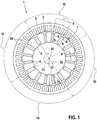
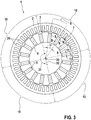
- FIG Figures 1 to 6 describes an electrical machine 1 with stator 2 and rotor 3 according to several examples. Identical or functionally identical components are provided with the same reference symbols in all examples.
- the figures show the electrical machine 1 schematically simplified. For the sake of clarity, for example, the windings on the stator 2 are hidden.
- Figures 1 , 3rd and 5 show the stator 2 with the rotor 3 arranged therein.
- the rotor 3 is arranged in the stator 2 so as to be rotatable about an axis of rotation 30.
- a circumferential direction 31 is defined around the axis of rotation 30.
- a radial direction 32 is perpendicular to the axis of rotation 30.
- the rotor 3 extends along the radial direction 32 with a rotor radius 33.
- the rotor 3 comprises a carrier 4, formed by a laminated core.
- the carrier 4 has cutouts, in each of which a magnet 5 is seated.
- the magnets 5 are designed as permanent magnets and arranged in a spoke shape.
- the cutouts in the carrier 4 are designed such that the magnets 5 can be inserted parallel to the axis of rotation 30.
- the magnets 5 extend along the radial direction 32 over a magnet length 34. Measured in the circumferential direction 31, the magnets 5 have a magnet width 9. The magnet length 34 is considerably larger than the magnet width 9.
- the magnetic poles N, S of the magnets 5 are aligned in the circumferential direction 31.
- the magnets 5 are arranged alternately, so that two south poles S and two north poles N are alternately directed towards each other.
- each pole 6 pointing outward in the radial direction 32 is referred to as the pole outer side 7.
- the pole outer side 7 is formed by the outward-facing side of the carrier 4 and the exposed portions of the outward-facing sides of the magnets 5.
- the outward-facing sides of the magnets 5 are partially covered with a covering 11 by the carrier 4.
- the figures also show a pole pitch ⁇ .
- the sum of all pole pitches ⁇ adds up to 360 °.
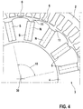
- the rotor 3 has four pole groups 10. Each pole group 10 is the same and comprises four poles 6. Each pole group extends over 90 ° in the examples shown.
- the poles 6 of the pole group 10 differ in the geometrical configuration of the overlap 11.
- the poles 6 in the clockwise direction along the circumferential direction 31 the first pole 6 has a slight overlap 11 on the magnetic pole of its first magnet 5 and a larger overlap 11 on the magnetic pole of its second magnet 5.
- the reverse arrangement results for the second pole 6, namely a larger overlap 11 on the magnetic pole of the first magnet 5 and less coverage 11 on the magnetic pole of the second magnet 5.
- poles 6 of the pole group 10 differ in the geometrical configuration of the pole outer side 7, in particular with regard to the carrier 4.
- this shows a pole 6 with a convex pole outer side 7 and a pole 6 with a straight pole outer side 7, a further pole 6 with a straight pole outside 7, and a pole 6 with a concave pole outside 7.
- the measures shown for designing different poles 6 within a pole group 10 can be combined with one another.
Claims (7)
- Rotor (3) d'une machine électrique (1), comprenant• un support ferromagnétique (4), et• une pluralité d'aimants (5) disposés en forme de rayons par rapport à l'axe de rotation (30) du rotor (3) de sorte que les pôles magnétiques (N, S) des aimants (5) sont alignés dans la direction circonférentielle (31) et des pôles magnétiques parallèles (N, S) se font face,• dans lequel respectivement deux pôles magnétiques (N, S) se faisant face et la partie du support (4) située entre ceux-ci forment un pôle (6) du rotor (3),• dans lequel au moins deux pôles (6) forment un groupe de pôles (10), le groupe de pôles (10) se répétant entièrement dans la direction circonférentielle (31), et• dans lequel, dans le groupe de pôles (10), au moins deux pôles (6) sont différents l'un de l'autre,o au moins deux pôles (6) dans le groupe de pôles (10) se distinguant par leur largeur de pôle (α), et∘ au moins deux pôles (6) dans le groupe de pôles (10) présentant des géométries différentes de leurs faces extérieures de pôle (7).
- Rotor selon la revendication 1, dans lequel, à l'intérieur du groupe de pôles (10), une première face extérieure de pôle (7) d'un premier pôle (6) est réalisée de manière concave et une deuxième face extérieure de pôle (7) d'un deuxième pôle (6) est réalisée de manière non concave ou est réalisée de manière concave avec un rayon plus grand que la première face extérieure de pôle (7).
- Rotor selon la revendication 1 ou 2, dans lequel, à l'intérieur du groupe de pôles (10), une première face extérieure de pôle (7) d'un premier pôle (6) est réalisée de manière convexe et une deuxième face extérieure de pôle (7) d'un deuxième pôle (6) est réalisée de manière non convexe ou est réalisée de manière convexe avec un rayon plus grand que la première face extérieure de pôle (7).
- Rotor selon l'une quelconque des revendications 1 à 3, dans lequel au moins deux pôles (6) du groupe de pôles (10) se distinguent dans le recouvrement (11) de la face extérieure radiale des aimants (5) par le support (4).
- Machine électrique (1), comprenant un rotor (3) selon l'une quelconque des revendications précédentes et un stator (2).
- Machine électrique selon la revendication 5, dans laquelle le stator (2) présente un bobinage intégral.
- Machine électrique selon la revendication 5 ou 6, dans laquelle le stator (2) présente un enroulement enfichable.
Applications Claiming Priority (1)
| Application Number | Priority Date | Filing Date | Title |
|---|---|---|---|
| DE102017216164.7A DE102017216164A1 (de) | 2017-09-13 | 2017-09-13 | Rotor einer elektrischen Maschine |
Publications (2)
| Publication Number | Publication Date |
|---|---|
| EP3457533A1 EP3457533A1 (fr) | 2019-03-20 |
| EP3457533B1 true EP3457533B1 (fr) | 2020-07-01 |
Family
ID=63350396
Family Applications (1)
| Application Number | Title | Priority Date | Filing Date |
|---|---|---|---|
| EP18189916.2A Active EP3457533B1 (fr) | 2017-09-13 | 2018-08-21 | Rotor pour une machine électrique |
Country Status (2)
| Country | Link |
|---|---|
| EP (1) | EP3457533B1 (fr) |
| DE (1) | DE102017216164A1 (fr) |
Families Citing this family (1)
| Publication number | Priority date | Publication date | Assignee | Title |
|---|---|---|---|---|
| EP4024667A4 (fr) * | 2019-08-26 | 2023-09-27 | Nidec Corporation | Moteur à aimants permanents intérieurs |
Family Cites Families (11)
| Publication number | Priority date | Publication date | Assignee | Title |
|---|---|---|---|---|
| JP2721061B2 (ja) * | 1991-11-14 | 1998-03-04 | ファナック株式会社 | コギングトルクを低減可能な同期電動機 |
| WO1998054822A1 (fr) | 1997-05-26 | 1998-12-03 | Denso Corporation | Alternateur pour vehicule |
| DE69904671T2 (de) | 1998-05-25 | 2003-07-31 | Denso Corp | Kraftfahrzeugwechselstromgenerator |
| DE60116944T2 (de) | 2000-11-06 | 2006-07-27 | Denso Corp., Kariya | Statoranordnung einer rotierenden elektrischen Maschine |
| EP1420500A1 (fr) * | 2002-11-15 | 2004-05-19 | Minebea Co., Ltd. | Ensemble de rotor destiné à une machine électrique |
| DE10315361A1 (de) | 2003-04-03 | 2004-10-14 | Robert Bosch Gmbh | Verfahren zur Herstellung von Wicklungen und Wicklungsverschaltungen |
| DE102006026402A1 (de) * | 2006-06-07 | 2007-12-13 | Robert Bosch Gmbh | Wechselstromgenerator für Kraftfahrzeuge |
| JP4910572B2 (ja) | 2006-08-30 | 2012-04-04 | 株式会社デンソー | 車両用回転電機 |
| JP5433198B2 (ja) * | 2008-10-16 | 2014-03-05 | 日立オートモティブシステムズ株式会社 | 回転電機及び電気自動車 |
| DE102009019555A1 (de) * | 2009-04-30 | 2010-11-04 | Minebea Co., Ltd. | Eisenkern für eine elektrische Maschine |
| US9716411B2 (en) * | 2013-01-24 | 2017-07-25 | Mitsubishi Electric Corporation | Permanent-magnet-type rotating electric mechanism |
-
2017
- 2017-09-13 DE DE102017216164.7A patent/DE102017216164A1/de active Pending
-
2018
- 2018-08-21 EP EP18189916.2A patent/EP3457533B1/fr active Active
Non-Patent Citations (1)
| Title |
|---|
| None * |
Also Published As
| Publication number | Publication date |
|---|---|
| DE102017216164A1 (de) | 2019-03-14 |
| EP3457533A1 (fr) | 2019-03-20 |
Similar Documents
| Publication | Publication Date | Title |
|---|---|---|
| EP2115858B1 (fr) | Machine électrique polyphase | |
| EP2483991B1 (fr) | Moteur synchrone sans balai | |
| EP3038233B1 (fr) | Moteur synchrone a aimant permanent et direction assistee electrique | |
| EP2160816A2 (fr) | Moteur synchrone à 12 dents statoriques et 10 pôles rotoriques | |
| DE102011008198A1 (de) | Stator für eine elektrische Maschine | |
| DE102010018443A1 (de) | Schrägungsmuster für einen Permanentmagnetrotor | |
| EP3146619B1 (fr) | Machine électrique | |
| DE102011011023A1 (de) | Elektrische Maschine | |
| WO2014166872A2 (fr) | Machine électrique | |
| DE102013110275A1 (de) | Stator für eine drehende elektrische Maschine | |
| DE102010032764A1 (de) | Elektrische Maschine und Stator für dieselbe | |
| DE112020005299T5 (de) | Statorwicklung mit wechselnden wicklungsschritten | |
| EP2550721B1 (fr) | Machine électrique et dispositif de direction | |
| DE112019006984T5 (de) | Generator-Motor und Herstellungsverfahren für einen Generator-Motor | |
| WO2013131795A2 (fr) | Rotor et machine électrique | |
| DE102014222064B4 (de) | Elektrische Maschine | |
| WO2018002128A1 (fr) | Rotor, procédé de fabrication d'un rotor, machine à reluctance et machine de travail | |
| DE102019112458A1 (de) | Rotierende elektrische maschine | |
| WO2019215097A1 (fr) | Procédé de fabrication d'un enroulement pour un stator d'une machine électrique et machine électrique | |
| EP3457533B1 (fr) | Rotor pour une machine électrique | |
| DE102011084716A1 (de) | Elektrische Maschine | |
| DE112020003317T5 (de) | Motor | |
| EP2532073B1 (fr) | Stator de machine électrique rotative à excitation permanente | |
| WO2021250162A1 (fr) | Stator destiné à une machine électrique et machine électrique | |
| EP3424129B1 (fr) | Machine asynchrone |
Legal Events
| Date | Code | Title | Description |
|---|---|---|---|
| PUAI | Public reference made under article 153(3) epc to a published international application that has entered the european phase |
Free format text: ORIGINAL CODE: 0009012 |
|
| STAA | Information on the status of an ep patent application or granted ep patent |
Free format text: STATUS: THE APPLICATION HAS BEEN PUBLISHED |
|
| AK | Designated contracting states |
Kind code of ref document: A1 Designated state(s): AL AT BE BG CH CY CZ DE DK EE ES FI FR GB GR HR HU IE IS IT LI LT LU LV MC MK MT NL NO PL PT RO RS SE SI SK SM TR |
|
| AX | Request for extension of the european patent |
Extension state: BA ME |
|
| STAA | Information on the status of an ep patent application or granted ep patent |
Free format text: STATUS: REQUEST FOR EXAMINATION WAS MADE |
|
| 17P | Request for examination filed |
Effective date: 20190920 |
|
| RBV | Designated contracting states (corrected) |
Designated state(s): AL AT BE BG CH CY CZ DE DK EE ES FI FR GB GR HR HU IE IS IT LI LT LU LV MC MK MT NL NO PL PT RO RS SE SI SK SM TR |
|
| GRAP | Despatch of communication of intention to grant a patent |
Free format text: ORIGINAL CODE: EPIDOSNIGR1 |
|
| STAA | Information on the status of an ep patent application or granted ep patent |
Free format text: STATUS: GRANT OF PATENT IS INTENDED |
|
| INTG | Intention to grant announced |
Effective date: 20200331 |
|
| RAP1 | Party data changed (applicant data changed or rights of an application transferred) |
Owner name: ROBERT BOSCH GMBH |
|
| GRAS | Grant fee paid |
Free format text: ORIGINAL CODE: EPIDOSNIGR3 |
|
| GRAA | (expected) grant |
Free format text: ORIGINAL CODE: 0009210 |
|
| STAA | Information on the status of an ep patent application or granted ep patent |
Free format text: STATUS: THE PATENT HAS BEEN GRANTED |
|
| AK | Designated contracting states |
Kind code of ref document: B1 Designated state(s): AL AT BE BG CH CY CZ DE DK EE ES FI FR GB GR HR HU IE IS IT LI LT LU LV MC MK MT NL NO PL PT RO RS SE SI SK SM TR |
|
| REG | Reference to a national code |
Ref country code: AT Ref legal event code: REF Ref document number: 1287091 Country of ref document: AT Kind code of ref document: T Effective date: 20200715 Ref country code: CH Ref legal event code: EP |
|
| REG | Reference to a national code |
Ref country code: IE Ref legal event code: FG4D Free format text: LANGUAGE OF EP DOCUMENT: GERMAN |
|
| REG | Reference to a national code |
Ref country code: DE Ref legal event code: R096 Ref document number: 502018001787 Country of ref document: DE |
|
| REG | Reference to a national code |
Ref country code: NL Ref legal event code: FP |
|
| REG | Reference to a national code |
Ref country code: LT Ref legal event code: MG4D |
|
| PG25 | Lapsed in a contracting state [announced via postgrant information from national office to epo] |
Ref country code: BG Free format text: LAPSE BECAUSE OF FAILURE TO SUBMIT A TRANSLATION OF THE DESCRIPTION OR TO PAY THE FEE WITHIN THE PRESCRIBED TIME-LIMIT Effective date: 20201001 |
|
| PG25 | Lapsed in a contracting state [announced via postgrant information from national office to epo] |
Ref country code: SE Free format text: LAPSE BECAUSE OF FAILURE TO SUBMIT A TRANSLATION OF THE DESCRIPTION OR TO PAY THE FEE WITHIN THE PRESCRIBED TIME-LIMIT Effective date: 20200701 Ref country code: HR Free format text: LAPSE BECAUSE OF FAILURE TO SUBMIT A TRANSLATION OF THE DESCRIPTION OR TO PAY THE FEE WITHIN THE PRESCRIBED TIME-LIMIT Effective date: 20200701 Ref country code: FI Free format text: LAPSE BECAUSE OF FAILURE TO SUBMIT A TRANSLATION OF THE DESCRIPTION OR TO PAY THE FEE WITHIN THE PRESCRIBED TIME-LIMIT Effective date: 20200701 Ref country code: CZ Free format text: LAPSE BECAUSE OF FAILURE TO SUBMIT A TRANSLATION OF THE DESCRIPTION OR TO PAY THE FEE WITHIN THE PRESCRIBED TIME-LIMIT Effective date: 20200701 Ref country code: LT Free format text: LAPSE BECAUSE OF FAILURE TO SUBMIT A TRANSLATION OF THE DESCRIPTION OR TO PAY THE FEE WITHIN THE PRESCRIBED TIME-LIMIT Effective date: 20200701 Ref country code: PT Free format text: LAPSE BECAUSE OF FAILURE TO SUBMIT A TRANSLATION OF THE DESCRIPTION OR TO PAY THE FEE WITHIN THE PRESCRIBED TIME-LIMIT Effective date: 20201102 Ref country code: NO Free format text: LAPSE BECAUSE OF FAILURE TO SUBMIT A TRANSLATION OF THE DESCRIPTION OR TO PAY THE FEE WITHIN THE PRESCRIBED TIME-LIMIT Effective date: 20201001 Ref country code: GR Free format text: LAPSE BECAUSE OF FAILURE TO SUBMIT A TRANSLATION OF THE DESCRIPTION OR TO PAY THE FEE WITHIN THE PRESCRIBED TIME-LIMIT Effective date: 20201002 Ref country code: ES Free format text: LAPSE BECAUSE OF FAILURE TO SUBMIT A TRANSLATION OF THE DESCRIPTION OR TO PAY THE FEE WITHIN THE PRESCRIBED TIME-LIMIT Effective date: 20200701 |
|
| PG25 | Lapsed in a contracting state [announced via postgrant information from national office to epo] |
Ref country code: IS Free format text: LAPSE BECAUSE OF FAILURE TO SUBMIT A TRANSLATION OF THE DESCRIPTION OR TO PAY THE FEE WITHIN THE PRESCRIBED TIME-LIMIT Effective date: 20201101 Ref country code: PL Free format text: LAPSE BECAUSE OF FAILURE TO SUBMIT A TRANSLATION OF THE DESCRIPTION OR TO PAY THE FEE WITHIN THE PRESCRIBED TIME-LIMIT Effective date: 20200701 Ref country code: RS Free format text: LAPSE BECAUSE OF FAILURE TO SUBMIT A TRANSLATION OF THE DESCRIPTION OR TO PAY THE FEE WITHIN THE PRESCRIBED TIME-LIMIT Effective date: 20200701 Ref country code: LV Free format text: LAPSE BECAUSE OF FAILURE TO SUBMIT A TRANSLATION OF THE DESCRIPTION OR TO PAY THE FEE WITHIN THE PRESCRIBED TIME-LIMIT Effective date: 20200701 |
|
| PG25 | Lapsed in a contracting state [announced via postgrant information from national office to epo] |
Ref country code: MC Free format text: LAPSE BECAUSE OF FAILURE TO SUBMIT A TRANSLATION OF THE DESCRIPTION OR TO PAY THE FEE WITHIN THE PRESCRIBED TIME-LIMIT Effective date: 20200701 |
|
| REG | Reference to a national code |
Ref country code: DE Ref legal event code: R097 Ref document number: 502018001787 Country of ref document: DE |
|
| PG25 | Lapsed in a contracting state [announced via postgrant information from national office to epo] |
Ref country code: DK Free format text: LAPSE BECAUSE OF FAILURE TO SUBMIT A TRANSLATION OF THE DESCRIPTION OR TO PAY THE FEE WITHIN THE PRESCRIBED TIME-LIMIT Effective date: 20200701 Ref country code: RO Free format text: LAPSE BECAUSE OF FAILURE TO SUBMIT A TRANSLATION OF THE DESCRIPTION OR TO PAY THE FEE WITHIN THE PRESCRIBED TIME-LIMIT Effective date: 20200701 Ref country code: EE Free format text: LAPSE BECAUSE OF FAILURE TO SUBMIT A TRANSLATION OF THE DESCRIPTION OR TO PAY THE FEE WITHIN THE PRESCRIBED TIME-LIMIT Effective date: 20200701 Ref country code: SM Free format text: LAPSE BECAUSE OF FAILURE TO SUBMIT A TRANSLATION OF THE DESCRIPTION OR TO PAY THE FEE WITHIN THE PRESCRIBED TIME-LIMIT Effective date: 20200701 Ref country code: LU Free format text: LAPSE BECAUSE OF NON-PAYMENT OF DUE FEES Effective date: 20200821 Ref country code: IT Free format text: LAPSE BECAUSE OF FAILURE TO SUBMIT A TRANSLATION OF THE DESCRIPTION OR TO PAY THE FEE WITHIN THE PRESCRIBED TIME-LIMIT Effective date: 20200701 |
|
| PLBE | No opposition filed within time limit |
Free format text: ORIGINAL CODE: 0009261 |
|
| STAA | Information on the status of an ep patent application or granted ep patent |
Free format text: STATUS: NO OPPOSITION FILED WITHIN TIME LIMIT |
|
| PG25 | Lapsed in a contracting state [announced via postgrant information from national office to epo] |
Ref country code: AL Free format text: LAPSE BECAUSE OF FAILURE TO SUBMIT A TRANSLATION OF THE DESCRIPTION OR TO PAY THE FEE WITHIN THE PRESCRIBED TIME-LIMIT Effective date: 20200701 |
|
| 26N | No opposition filed |
Effective date: 20210406 |
|
| PG25 | Lapsed in a contracting state [announced via postgrant information from national office to epo] |
Ref country code: SK Free format text: LAPSE BECAUSE OF FAILURE TO SUBMIT A TRANSLATION OF THE DESCRIPTION OR TO PAY THE FEE WITHIN THE PRESCRIBED TIME-LIMIT Effective date: 20200701 |
|
| PG25 | Lapsed in a contracting state [announced via postgrant information from national office to epo] |
Ref country code: FR Free format text: LAPSE BECAUSE OF NON-PAYMENT OF DUE FEES Effective date: 20200901 |
|
| PG25 | Lapsed in a contracting state [announced via postgrant information from national office to epo] |
Ref country code: IE Free format text: LAPSE BECAUSE OF NON-PAYMENT OF DUE FEES Effective date: 20200821 Ref country code: SI Free format text: LAPSE BECAUSE OF FAILURE TO SUBMIT A TRANSLATION OF THE DESCRIPTION OR TO PAY THE FEE WITHIN THE PRESCRIBED TIME-LIMIT Effective date: 20200701 |
|
| PGFP | Annual fee paid to national office [announced via postgrant information from national office to epo] |
Ref country code: BE Payment date: 20210823 Year of fee payment: 4 Ref country code: CH Payment date: 20210824 Year of fee payment: 4 |
|
| PG25 | Lapsed in a contracting state [announced via postgrant information from national office to epo] |
Ref country code: TR Free format text: LAPSE BECAUSE OF FAILURE TO SUBMIT A TRANSLATION OF THE DESCRIPTION OR TO PAY THE FEE WITHIN THE PRESCRIBED TIME-LIMIT Effective date: 20200701 Ref country code: MT Free format text: LAPSE BECAUSE OF FAILURE TO SUBMIT A TRANSLATION OF THE DESCRIPTION OR TO PAY THE FEE WITHIN THE PRESCRIBED TIME-LIMIT Effective date: 20200701 Ref country code: CY Free format text: LAPSE BECAUSE OF FAILURE TO SUBMIT A TRANSLATION OF THE DESCRIPTION OR TO PAY THE FEE WITHIN THE PRESCRIBED TIME-LIMIT Effective date: 20200701 |
|
| PG25 | Lapsed in a contracting state [announced via postgrant information from national office to epo] |
Ref country code: MK Free format text: LAPSE BECAUSE OF FAILURE TO SUBMIT A TRANSLATION OF THE DESCRIPTION OR TO PAY THE FEE WITHIN THE PRESCRIBED TIME-LIMIT Effective date: 20200701 |
|
| REG | Reference to a national code |
Ref country code: CH Ref legal event code: PL |
|
| GBPC | Gb: european patent ceased through non-payment of renewal fee |
Effective date: 20220821 |
|
| PG25 | Lapsed in a contracting state [announced via postgrant information from national office to epo] |
Ref country code: LI Free format text: LAPSE BECAUSE OF NON-PAYMENT OF DUE FEES Effective date: 20220831 Ref country code: CH Free format text: LAPSE BECAUSE OF NON-PAYMENT OF DUE FEES Effective date: 20220831 |
|
| REG | Reference to a national code |
Ref country code: BE Ref legal event code: MM Effective date: 20220831 |
|
| PG25 | Lapsed in a contracting state [announced via postgrant information from national office to epo] |
Ref country code: BE Free format text: LAPSE BECAUSE OF NON-PAYMENT OF DUE FEES Effective date: 20220831 |
|
| PGFP | Annual fee paid to national office [announced via postgrant information from national office to epo] |
Ref country code: NL Payment date: 20230823 Year of fee payment: 6 |
|
| PG25 | Lapsed in a contracting state [announced via postgrant information from national office to epo] |
Ref country code: GB Free format text: LAPSE BECAUSE OF NON-PAYMENT OF DUE FEES Effective date: 20220821 |
|
| PGFP | Annual fee paid to national office [announced via postgrant information from national office to epo] |
Ref country code: DE Payment date: 20231025 Year of fee payment: 6 |