EP3457464B1 - Method for injecting electrolyte into pouch secondary battery using gap-controlling jig - Google Patents
Method for injecting electrolyte into pouch secondary battery using gap-controlling jig Download PDFInfo
- Publication number
- EP3457464B1 EP3457464B1 EP17880635.2A EP17880635A EP3457464B1 EP 3457464 B1 EP3457464 B1 EP 3457464B1 EP 17880635 A EP17880635 A EP 17880635A EP 3457464 B1 EP3457464 B1 EP 3457464B1
- Authority
- EP
- European Patent Office
- Prior art keywords
- electrolyte
- pouch
- secondary battery
- injecting
- jig
- Prior art date
- Legal status (The legal status is an assumption and is not a legal conclusion. Google has not performed a legal analysis and makes no representation as to the accuracy of the status listed.)
- Active
Links
Images


Classifications
-
- H—ELECTRICITY
- H01—ELECTRIC ELEMENTS
- H01M—PROCESSES OR MEANS, e.g. BATTERIES, FOR THE DIRECT CONVERSION OF CHEMICAL ENERGY INTO ELECTRICAL ENERGY
- H01M10/00—Secondary cells; Manufacture thereof
- H01M10/42—Methods or arrangements for servicing or maintenance of secondary cells or secondary half-cells
- H01M10/4235—Safety or regulating additives or arrangements in electrodes, separators or electrolyte
-
- H—ELECTRICITY
- H01—ELECTRIC ELEMENTS
- H01M—PROCESSES OR MEANS, e.g. BATTERIES, FOR THE DIRECT CONVERSION OF CHEMICAL ENERGY INTO ELECTRICAL ENERGY
- H01M10/00—Secondary cells; Manufacture thereof
- H01M10/05—Accumulators with non-aqueous electrolyte
- H01M10/052—Li-accumulators
-
- H—ELECTRICITY
- H01—ELECTRIC ELEMENTS
- H01M—PROCESSES OR MEANS, e.g. BATTERIES, FOR THE DIRECT CONVERSION OF CHEMICAL ENERGY INTO ELECTRICAL ENERGY
- H01M10/00—Secondary cells; Manufacture thereof
- H01M10/42—Methods or arrangements for servicing or maintenance of secondary cells or secondary half-cells
- H01M10/4214—Arrangements for moving electrodes or electrolyte
-
- H—ELECTRICITY
- H01—ELECTRIC ELEMENTS
- H01M—PROCESSES OR MEANS, e.g. BATTERIES, FOR THE DIRECT CONVERSION OF CHEMICAL ENERGY INTO ELECTRICAL ENERGY
- H01M50/00—Constructional details or processes of manufacture of the non-active parts of electrochemical cells other than fuel cells, e.g. hybrid cells
- H01M50/10—Primary casings; Jackets or wrappings
- H01M50/102—Primary casings; Jackets or wrappings characterised by their shape or physical structure
- H01M50/105—Pouches or flexible bags
-
- H—ELECTRICITY
- H01—ELECTRIC ELEMENTS
- H01M—PROCESSES OR MEANS, e.g. BATTERIES, FOR THE DIRECT CONVERSION OF CHEMICAL ENERGY INTO ELECTRICAL ENERGY
- H01M50/00—Constructional details or processes of manufacture of the non-active parts of electrochemical cells other than fuel cells, e.g. hybrid cells
- H01M50/10—Primary casings; Jackets or wrappings
- H01M50/116—Primary casings; Jackets or wrappings characterised by the material
- H01M50/117—Inorganic material
- H01M50/119—Metals
-
- H—ELECTRICITY
- H01—ELECTRIC ELEMENTS
- H01M—PROCESSES OR MEANS, e.g. BATTERIES, FOR THE DIRECT CONVERSION OF CHEMICAL ENERGY INTO ELECTRICAL ENERGY
- H01M50/00—Constructional details or processes of manufacture of the non-active parts of electrochemical cells other than fuel cells, e.g. hybrid cells
- H01M50/10—Primary casings; Jackets or wrappings
- H01M50/116—Primary casings; Jackets or wrappings characterised by the material
- H01M50/121—Organic material
-
- H—ELECTRICITY
- H01—ELECTRIC ELEMENTS
- H01M—PROCESSES OR MEANS, e.g. BATTERIES, FOR THE DIRECT CONVERSION OF CHEMICAL ENERGY INTO ELECTRICAL ENERGY
- H01M50/00—Constructional details or processes of manufacture of the non-active parts of electrochemical cells other than fuel cells, e.g. hybrid cells
- H01M50/10—Primary casings; Jackets or wrappings
- H01M50/116—Primary casings; Jackets or wrappings characterised by the material
- H01M50/122—Composite material consisting of a mixture of organic and inorganic materials
-
- H—ELECTRICITY
- H01—ELECTRIC ELEMENTS
- H01M—PROCESSES OR MEANS, e.g. BATTERIES, FOR THE DIRECT CONVERSION OF CHEMICAL ENERGY INTO ELECTRICAL ENERGY
- H01M50/00—Constructional details or processes of manufacture of the non-active parts of electrochemical cells other than fuel cells, e.g. hybrid cells
- H01M50/10—Primary casings; Jackets or wrappings
- H01M50/116—Primary casings; Jackets or wrappings characterised by the material
- H01M50/124—Primary casings; Jackets or wrappings characterised by the material having a layered structure
- H01M50/126—Primary casings; Jackets or wrappings characterised by the material having a layered structure comprising three or more layers
-
- H—ELECTRICITY
- H01—ELECTRIC ELEMENTS
- H01M—PROCESSES OR MEANS, e.g. BATTERIES, FOR THE DIRECT CONVERSION OF CHEMICAL ENERGY INTO ELECTRICAL ENERGY
- H01M50/00—Constructional details or processes of manufacture of the non-active parts of electrochemical cells other than fuel cells, e.g. hybrid cells
- H01M50/60—Arrangements or processes for filling or topping-up with liquids; Arrangements or processes for draining liquids from casings
- H01M50/609—Arrangements or processes for filling with liquid, e.g. electrolytes
- H01M50/618—Pressure control
-
- H—ELECTRICITY
- H01—ELECTRIC ELEMENTS
- H01M—PROCESSES OR MEANS, e.g. BATTERIES, FOR THE DIRECT CONVERSION OF CHEMICAL ENERGY INTO ELECTRICAL ENERGY
- H01M50/00—Constructional details or processes of manufacture of the non-active parts of electrochemical cells other than fuel cells, e.g. hybrid cells
- H01M50/60—Arrangements or processes for filling or topping-up with liquids; Arrangements or processes for draining liquids from casings
- H01M50/609—Arrangements or processes for filling with liquid, e.g. electrolytes
- H01M50/627—Filling ports
- H01M50/636—Closing or sealing filling ports, e.g. using lids
-
- H—ELECTRICITY
- H01—ELECTRIC ELEMENTS
- H01M—PROCESSES OR MEANS, e.g. BATTERIES, FOR THE DIRECT CONVERSION OF CHEMICAL ENERGY INTO ELECTRICAL ENERGY
- H01M2220/00—Batteries for particular applications
- H01M2220/30—Batteries in portable systems, e.g. mobile phone, laptop
-
- H—ELECTRICITY
- H01—ELECTRIC ELEMENTS
- H01M—PROCESSES OR MEANS, e.g. BATTERIES, FOR THE DIRECT CONVERSION OF CHEMICAL ENERGY INTO ELECTRICAL ENERGY
- H01M50/00—Constructional details or processes of manufacture of the non-active parts of electrochemical cells other than fuel cells, e.g. hybrid cells
- H01M50/10—Primary casings; Jackets or wrappings
- H01M50/172—Arrangements of electric connectors penetrating the casing
- H01M50/174—Arrangements of electric connectors penetrating the casing adapted for the shape of the cells
- H01M50/178—Arrangements of electric connectors penetrating the casing adapted for the shape of the cells for pouch or flexible bag cells
-
- H—ELECTRICITY
- H01—ELECTRIC ELEMENTS
- H01M—PROCESSES OR MEANS, e.g. BATTERIES, FOR THE DIRECT CONVERSION OF CHEMICAL ENERGY INTO ELECTRICAL ENERGY
- H01M50/00—Constructional details or processes of manufacture of the non-active parts of electrochemical cells other than fuel cells, e.g. hybrid cells
- H01M50/50—Current conducting connections for cells or batteries
- H01M50/543—Terminals
- H01M50/547—Terminals characterised by the disposition of the terminals on the cells
- H01M50/55—Terminals characterised by the disposition of the terminals on the cells on the same side of the cell
-
- H—ELECTRICITY
- H01—ELECTRIC ELEMENTS
- H01M—PROCESSES OR MEANS, e.g. BATTERIES, FOR THE DIRECT CONVERSION OF CHEMICAL ENERGY INTO ELECTRICAL ENERGY
- H01M50/00—Constructional details or processes of manufacture of the non-active parts of electrochemical cells other than fuel cells, e.g. hybrid cells
- H01M50/50—Current conducting connections for cells or batteries
- H01M50/543—Terminals
- H01M50/552—Terminals characterised by their shape
- H01M50/553—Terminals adapted for prismatic, pouch or rectangular cells
- H01M50/557—Plate-shaped terminals
-
- H—ELECTRICITY
- H01—ELECTRIC ELEMENTS
- H01M—PROCESSES OR MEANS, e.g. BATTERIES, FOR THE DIRECT CONVERSION OF CHEMICAL ENERGY INTO ELECTRICAL ENERGY
- H01M50/00—Constructional details or processes of manufacture of the non-active parts of electrochemical cells other than fuel cells, e.g. hybrid cells
- H01M50/50—Current conducting connections for cells or batteries
- H01M50/543—Terminals
- H01M50/564—Terminals characterised by their manufacturing process
- H01M50/566—Terminals characterised by their manufacturing process by welding, soldering or brazing
-
- Y—GENERAL TAGGING OF NEW TECHNOLOGICAL DEVELOPMENTS; GENERAL TAGGING OF CROSS-SECTIONAL TECHNOLOGIES SPANNING OVER SEVERAL SECTIONS OF THE IPC; TECHNICAL SUBJECTS COVERED BY FORMER USPC CROSS-REFERENCE ART COLLECTIONS [XRACs] AND DIGESTS
- Y02—TECHNOLOGIES OR APPLICATIONS FOR MITIGATION OR ADAPTATION AGAINST CLIMATE CHANGE
- Y02E—REDUCTION OF GREENHOUSE GAS [GHG] EMISSIONS, RELATED TO ENERGY GENERATION, TRANSMISSION OR DISTRIBUTION
- Y02E60/00—Enabling technologies; Technologies with a potential or indirect contribution to GHG emissions mitigation
- Y02E60/10—Energy storage using batteries
-
- Y—GENERAL TAGGING OF NEW TECHNOLOGICAL DEVELOPMENTS; GENERAL TAGGING OF CROSS-SECTIONAL TECHNOLOGIES SPANNING OVER SEVERAL SECTIONS OF THE IPC; TECHNICAL SUBJECTS COVERED BY FORMER USPC CROSS-REFERENCE ART COLLECTIONS [XRACs] AND DIGESTS
- Y02—TECHNOLOGIES OR APPLICATIONS FOR MITIGATION OR ADAPTATION AGAINST CLIMATE CHANGE
- Y02P—CLIMATE CHANGE MITIGATION TECHNOLOGIES IN THE PRODUCTION OR PROCESSING OF GOODS
- Y02P70/00—Climate change mitigation technologies in the production process for final industrial or consumer products
- Y02P70/50—Manufacturing or production processes characterised by the final manufactured product
Definitions
- the present disclosure relates to a method for injecting an electrolyte to a pouch secondary battery. More particularly, the present disclosure relates to a method for injecting an electrolyte which includes controlling the level of a liquid surface upon the injection of an electrolyte to a pouch secondary battery to reduce the tack time of a liquid injection step and to improve productivity.
- prismatic secondary batteries and pouch type secondary batteries which have a small thickness and can be applied to products, such as cellular phones, are in high demand.
- lithium secondary batteries such as lithium-ion batteries and lithium-ion polymer batteries, which have high energy density, discharge voltage and output stability, are in high demand.
- a pouch secondary battery provided with a structure in which a stack-type or stack/folded electrode assembly is received in a pouch casing including a metal (Al) laminate film has been given many attentions as a lithium secondary battery and use thereof has been increased gradually, since it requires low manufacturing cost, has a low weight and is easily deformable.
- a pouch secondary battery is manufactured through the following process. First, electrode plates and porous insulating separators are stacked to form an electrode assembly. The separator is interposed between a positive electrode plate and a negative electrode plate.
- Each of the positive electrode plate and negative electrode plate is coated with an active material.
- Typical examples of the positive electrode active material and the negative electrode active material include lithium metal oxide and graphite, respectively.
- Each electrode plate has a protruding and extended electrode tab, and the electrode tab is connected to an electrode lead.
- the electrode assembly to which the electrode lead is connected is placed between two sheets of metal laminate films.
- such two sheets of metal laminate films form a pouch casing.
- the edges of the metal laminate films are sealed with an electrolyte inlet left therein. Then, an electrolyte is injected through the electrolyte inlet and the electrolyte inlet is sealed so that the electrode assembly may be sealed in the pouch casing.
- a conventional process for injecting an electrolyte includes a pre-process of injecting an electrolyte to a pouch casing, and a post-process of loading the pouch casing having the electrolyte injected thereto to a vacuum chamber and removing the gases present in the electrode assembly.
- the gases originate from the air remaining in the inner space of the pouch casing and the fine gap present in the electrode assembly, when the electrolyte is injected to the pouch casing.
- the electrolyte may be ejected to the outside through the electrolyte inlet while the gases are emitted rapidly.
- the pre-vacuum post-injection process requires a time during which vacuum atmosphere is formed, before injecting the electrolyte, and thus still causes an increase in the tack time of the process.
- the electrolyte evaporates. Further, it is inevitable to modify a liquid injection system significantly, since a vacuum chamber and a depressurization device are further added into a system for injecting an electrolyte.
- KR 2016-0086196 discloses electrolyte injection apparatus.
- the present disclosure is designed to solve the problems of the related art, and therefore the present disclosure is directed to providing a method for injecting an electrolyte which reduces the tack time of a process for injecting an electrolyte to a pouch secondary battery and allows easy removal of gases from the inside of a pouch casing.
- a method for injecting an electrolyte to a pouch secondary battery which includes the steps of: 1) interposing an electrode assembly between a first metal laminate film and a second metal laminate film forming a pouch casing, and sealing the edges of each of the films with an electrolyte inlet left therein, thereby providing a pouch secondary battery; 2) mounting the pouch secondary battery between a first jig and a second jig, which are installed in a jig stand so as to have a controllable interval and form a gap space, with the electrolyte inlet facing up, and injecting an electrolyte through the electrolyte inlet; 3) loading the jig stand to a vacuum chamber; 4) increasing the width of the gap space by moving the first and the second jigs so that the area occupied by the electrolyte may be localized in the lower part of the pouch casing, and then forming vacuum atmosphere; and 5) moving the first and the second jigs so that the area occupied by the electroly
- the liquid surface of the electrolyte may be located at a position corresponding to 1/2h or less based on the height h of the electrode assembly.
- the method for injecting an electrolyte according to the present disclosure may further include a step of sealing the electrolyte inlet.
- the same degree of vacuum may be applied to the vacuum atmosphere.
- the degree of vacuum of the vacuum atmosphere may be -93 kPa or less.
- the first jig and the second jig have an interval increased so that they may not pressurize the outer circumferential surface of the pouch casing substantially.
- step 5 the width of the gap space is reduced gradually at the same rate.
- step 5 the width of the gap space is reduced gradually, wherein the reduction rate is increased gradually with time.
- the width of the gap space is increased while inserting a blower to the electrolyte inlet and spraying gas toward the inside of the pouch casing, in step 4).
- the blower preferably sprays gas toward the side wall of the pouch casing.
- the vacuum atmosphere is formed preferably after spraying gas by using the blower.
- FIG. 1-FIG. 7 are schematic views illustrating the method for injecting an electrolyte to a pouch secondary battery according to an embodiment of the present disclosure.
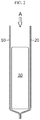
- an electrode assembly 30 is located between a first metal laminate film 10 and a second metal laminate film 20.
- the first and the second metal laminate films 10, 20 form a pouch casing.
- Each of the first and the second metal laminate films 10, 20 has a structure in which a thin metal film (e.g., Al film) is laminated between a water-resistant polymer film (nylon) and a thermally adhesive polymer film (casted polypropylene).
- a thin metal film e.g., Al film
- nylon water-resistant polymer film
- a thermally adhesive polymer film casted polypropylene
- each of the first and the second metal laminate film is generally known in the art, and thus the detailed description thereof will be omitted herein.
- the electrode assembly 30 includes a structure in which electrode plates and separators are stacked alternately.
- the electrode assembly 30 includes a plurality of unit cells including a positive electrode plate/separator/negative electrode plate.
- Each electrode plate has protruding electrode tabs 31, 32.
- the electrode tabs are integrated and are connected with an electrode leads 33, 34.
- the electrode tabs 31, 32 and the electrode leads 33, 34 one has positive polarity, and the other has negative polarity.
- the electrode tabs 31, 32 and the electrode leads 33, 34 are connected with each other so that the polarity of one may correspond to the polarity of the other. The connection is carried out by ultrasonic welding.
- the electrode leads 33, 34 are surrounded with a sealing tape 35 at its middle portion.
- the sealing tape 35 is interposed between the electrode leads 33, 34 and the first and the second metal laminate films 10, 20 to improve sealability.
- each of the first and the second metal laminate films 10, 20 are sealed by a hot sealing process with an electrolyte inject A left therein.
- the hatched region S shows the region where sealing is carried out.
- the first and the second metal laminate films 10, 20 form a pouch casing P.
- the remaining portion of the electrode assembly 30 except that the end of the electrode leads 33, 34 is surrounded with the first and the second metal laminate films 10, 20.
- the shape of the pouch secondary battery before injecting an electrolyte is shown at the lower part of FIG. 1 .
- FIG. 2 is a sectional view taken along line I-I' of FIG. 1 .
- the electrolyte inlet A is opened toward the external air, since it is not sealed.
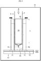
- FIG. 3-FIG. 7 are schematic views illustrating a process for removing gases and sealing the electrolyte inlet in the vacuum chamber, after injecting an electrolyte into the pouch casing P through the electrolyte inlet A.
- the pouch secondary battery B is located in a gap space G of a gap-controlling jig 40 provided with a first jig 41 and a second jig 42 capable of controlling a gap interval.
- the pouch secondary battery B is located with the electrolyte inlet facing up.
- the gap space G is formed between the first jig 41 and the second jig 42, and the width thereof may be controlled by moving the first jig 41 and the second jig 42 linearly.
- the first jig 41 and the second jig 42 may be made of a material including a metal, such as stainless steel.
- the first jig 41 and the second jig 42 are installed on a jig stand 43 so that they move from side to side.
- the width of the gap space G may be varied through the movement of the first jig 41 and the second jig 42.
- the jig stand 43 may be provided with a driving mechanism D which can move the first jig 41 and the second jig 42 from side to side.
- the driving mechanism D may include a moving block 51 to which the bottom portions of the first jig 41 and the second jig 42 are coupled, a guide rail 52 configured to receive the moving block 51 and guide the linear horizontal movement, and a linear motor M coupled to the moving block 51 to provide linear driving force.
- a support member 50 is provided in the bottom of the gap space G, and the bottom portion of the pouch secondary battery B is installed to the support member in contact with each other.
- the portion where the support member 50 faces the pouch secondary battery B has a shape corresponding to the shape of the contact surface of the pouch secondary battery B.
- the pouch secondary battery B is received in and supported by the top surface of the support member 50.
- the support member 50 includes a metallic or plastic material.
- the first jig 41 and the second jig 42 are allowed to be in close contact with the outer circumferential surface of the pouch secondary battery B. Then, an electrolyte 60 is injected through the electrolyte inlet A.
- the electrolyte 60 includes an electrolyte and an organic solvent, and the injection amount is predetermined depending on the specifications of the pouch secondary battery B.
- the electrolyte 60 varies with the type of the pouch secondary battery B.
- the electrolyte may be a salt having a structure of A + B - .
- a + includes an alkali metal cation such as Li + , Na + , K + or a combination thereof.
- B - includes at least one anion selected from the group consisting of F - , Cl - , Br - , I - , NO 3 - , N(CN) 2 - , BF 4 - , ClO 4 - , AlO 4 - , AlCl 4 - , PF 6 - , SbF 6 - , AsF 6 - , BF 2 C 2 O 4 - , BC 4 O 8 - , (CF 3 ) 2 PF 4 - , (CF 3 ) 3 PF 3 - , (CF 3 ) 4 PF 2 - , (CF 3 ) 5 PF - , (CF 3 ) 6 P - , CF 3 SO 3 - , C 4 F 9 SO 3 - , CF 3 CF 2 SO 3 - , (CF 3 SO 2 ) 2 N - , (FSO 2 ) 2 N - , CF 3 CF 2 (CF 3 ) 2 CO
- Non-limiting examples of the organic solvent may include propylene carbonate (PC), ethylene carbonate (EC), diethyl carbonate (DEC), dimethyl carbonate (DMC), dipropyl carbonate(DPC), dimethyl sulfoxide, acetonitrile, dimethoxyethane, diethoxyethane, tetrahydrofuran, N-methyl-2-pyrrolidone (NMP), ethyl methyl carbonate (EMC), gamma-butyrolactone or a combination thereof.
- PC propylene carbonate
- EC ethylene carbonate
- DEC diethyl carbonate
- DMC dimethyl carbonate
- DPC dipropyl carbonate
- the jig stand 43 is transported to the inside of the vacuum chamber 70 as shown in FIG. 4 . Then, the first jig 41 and the second jig 42 are moved to increase the width of the gap space G.
- the gap space G is increased, the liquid surface of the electrolyte 60 is lowered since the electrolyte 60 moves toward the lower part of the pouch casing P under the gravity. In other words, the region having the electrolyte 60 is localized in the lower part of the pouch casing P.
- the electrolyte 60 moves toward the lower part, the lower part of the pouch casing P is also deformed into a slightly swelled shape.
- the increment of the gap space G is predetermined so that the movement of the electrolyte 60 toward the lower part may not be interrupted.
- the gap space G is increased to such a degree that the gap space is not in contact with the outer circumferential surface of the pouch casing P.
- the gap space G is increased in such a manner that the first jig 41 and the second jig 42 apply no pressure substantially even if they are in contact with the pouch casing P.
- Such increment of the gap space G is accomplished by allowing the driving mechanism D to cause linear movement of the first jig 41 and the second jig 42.
- the liquid surface of the electrolyte 60 is lowered preferably to 2/3h or less, more preferably 1/2h or less, based on the initial injection height h in the electrode assembly 30.
- the position of the liquid surface is controlled based on the region where the electrode assembly 30 is present. In the liquid surface is at 1/2h, the liquid surface is located in the middle of the electrode assembly 30. Lowering the liquid surface of the electrolyte 60 to the maximum degree is more effective to remove the gases present in the electrode assembly 30.
- a blower 80 is inserted to the electrolyte inlet 80 and inert gas (Ar) or nitrogen gas (N 2 ) may be blown into the pouch casing P, while the first jig 41 and the second jig 42 are spaced apart from each other to increase the gap space G.
- the blower 80 has a Y-shaped nozzle structure and sprays gas toward the side wall of the pouch casing P.
- the amount of sprayed gas may be increased gradually to prevent the electrolyte 60 from being ejected at the initial stage of gas spray.
- the blown gas causes deformation of the shape of the pouch casing P into the shape as shown in FIG.
- blower 80 is particularly advisable when a high-viscosity electrolyte 60 is used. Such a high-viscosity electrolyte 60 requires a longer time to be moved to the lower part of the pouch casing P.
- depressurization for forming vacuum atmosphere inside the vacuum chamber 70 is initiated preferably after completing the gas spray using the blower 80.
- the degree of vacuum in the vacuum chamber 70 is decreased.
- a preferred degree of vacuum is controlled to such a degree that the gases present in the pouch casing P and the electrode assembly 30 may be removed effectively.
- a particular degree of vacuum may be determined by trial and error.
- the degree of vacuum of the vacuum chamber 70 is set to -93 kPa or less. In other words, the absolute value of the degree of vacuum is set to be larger than 93 and to have a negative value.
- the degree of vacuum of the vacuum chamber 70 is increased after the liquid surface of the electrolyte 60 is lowered, the electrode assembly 30 exposed above the top of the liquid surface of the electrolyte 60 is exposed directly to the vacuum atmosphere. Thus, the gases present in the electrode assembly are removed effectively.
- the time during which the degree of vacuum is maintained is set to ensure removal of the gases from the electrode assembly 30 exposed above the top of the liquid surface of the electrolyte 60 substantially.
- the time during which the degree of vacuum is maintained is set to 5 minutes or more.
- the process as shown in FIG. 5 is carried out.
- the first jig 41 and the second jig 42 are moved again to reduce the width of the gap space G gradually.
- the degree of vacuum is maintained substantially the same as in the gas removing process.
- the first jig 41 and the second jig 42 pressurize the outer circumferential surface of the pouch casing P gradually.
- the blower 80 is drawn out to the outside of the pouch casing P. As a result, the liquid surface of the electrolyte 60 is lifted gradually.
- the degree of vacuum formed originally is maintained continuously while the liquid surface of the electrolyte 60 is lifted gradually. Therefore, the electrode assembly exposed above the top based on the liquid surface of the electrolyte 60 is exposed to vacuum atmosphere, and thus even a trace amount of gases present in the electrode assembly are removed totally.
- the liquid surface of the electrolyte 60 is present at the lowest position, most gases are removed by the vacuum atmosphere. Therefore, even if the degree of vacuum formed originally is maintained continuously while the liquid surface of the electrolyte 60 is lifted, the amount of gases removed herein is significantly small. As a result, it is possible to solve the problem of electrolyte ejection caused by rapid emission of gases fundamentally.
- the width of the gap space G may be reduced gradually at the same rate.
- the width of the gap space G is reduced gradually while increasing the reduction rate gradually. In order to prevent ejection of the electrolyte 60, this is more preferred.
- the first and the second metal laminate films 10, 20 corresponding to the electrolyte inlet A are sealed as shown in FIG. 7 , thereby finishing the electrolyte injection process.
- the sealing of the electrolyte inlet A may be carried out after converting the vacuum atmosphere in the vacuum chamber 70 into ambient pressure or may be carried out in the external air after discharging the jig stand 43 to the outside of the vacuum chamber 70.
- the present disclosure it is possible to further increase the degree of vacuum in the vacuum chamber 70 during the process for removing gases after injecting an electrolyte 60, as compared to the conventional method. It is also possible to maintain a high degree of vacuum from the initial stage. Most gases are removed while the liquid surface of the electrolyte 60 is lowered. During the gas removal, as the liquid surface of the electrolyte 60 is low, the electrolyte 60 is not dispersed or ejected to the outside of the electrolyte inlet A even when the degree of vacuum is high.
- the degree of vacuum of the vacuum chamber 70 was increased gradually through the four steps, considering the ejection of the electrolyte 60: -75 kPa for 5 minutes, -80 kPa for 5 minutes, -85 kPa for 5 minutes, and -93 kPa for 5 minutes.
- the method for injecting an electrolyte according to the present disclosure can reduce a tack time and can remove the gases present in the electrode assembly 30 more effectively. As a result, it is possible to reduce defect generation and to improve productivity.
Landscapes
- Chemical & Material Sciences (AREA)
- Chemical Kinetics & Catalysis (AREA)
- Electrochemistry (AREA)
- General Chemical & Material Sciences (AREA)
- Engineering & Computer Science (AREA)
- Manufacturing & Machinery (AREA)
- Inorganic Chemistry (AREA)
- Composite Materials (AREA)
- Materials Engineering (AREA)
- Filling, Topping-Up Batteries (AREA)
- Secondary Cells (AREA)
Priority Applications (1)
| Application Number | Priority Date | Filing Date | Title |
|---|---|---|---|
| PL17880635T PL3457464T3 (pl) | 2016-12-15 | 2017-12-11 | Sposób wstrzykiwania elektrolitu do saszetkowej baterii akumulatorowej z użyciem uchwytu regulującego przerwę |
Applications Claiming Priority (3)
| Application Number | Priority Date | Filing Date | Title |
|---|---|---|---|
| KR20160171928 | 2016-12-15 | ||
| KR1020170168534A KR102079781B1 (ko) | 2016-12-15 | 2017-12-08 | 갭 조절 지그를 이용한 파우치 이차전지의 전해액 주입 방법 |
| PCT/KR2017/014472 WO2018110919A1 (ko) | 2016-12-15 | 2017-12-11 | 갭 조절 지그를 이용한 파우치 이차전지의 전해액 주입 방법 |
Publications (3)
| Publication Number | Publication Date |
|---|---|
| EP3457464A1 EP3457464A1 (en) | 2019-03-20 |
| EP3457464A4 EP3457464A4 (en) | 2019-06-05 |
| EP3457464B1 true EP3457464B1 (en) | 2020-04-15 |
Family
ID=62806435
Family Applications (1)
| Application Number | Title | Priority Date | Filing Date |
|---|---|---|---|
| EP17880635.2A Active EP3457464B1 (en) | 2016-12-15 | 2017-12-11 | Method for injecting electrolyte into pouch secondary battery using gap-controlling jig |
Country Status (5)
| Country | Link |
|---|---|
| US (1) | US10978749B2 (pl) |
| EP (1) | EP3457464B1 (pl) |
| KR (1) | KR102079781B1 (pl) |
| CN (1) | CN109417156B (pl) |
| PL (1) | PL3457464T3 (pl) |
Cited By (1)
| Publication number | Priority date | Publication date | Assignee | Title |
|---|---|---|---|---|
| EP4418381A3 (en) * | 2023-01-25 | 2024-11-06 | Prime Planet Energy & Solutions, Inc. | Manufacturing method of secondary battery and utilization thereof |
Families Citing this family (10)
| Publication number | Priority date | Publication date | Assignee | Title |
|---|---|---|---|---|
| KR102378374B1 (ko) | 2018-06-18 | 2022-03-25 | 주식회사 엘지에너지솔루션 | 버스바를 구비한 배터리 모듈 및 배터리 팩 |
| CN114303284B (zh) * | 2019-11-25 | 2024-04-30 | 株式会社Lg新能源 | 电解质注入装置和使用该电解质注入装置的电解质注入方法 |
| KR102835332B1 (ko) * | 2019-12-09 | 2025-07-17 | 주식회사 엘지에너지솔루션 | 보호필름을 이용한 파우치형 전지셀의 제조방법 및 이를 이용하여 제조된 파우치형 전지셀 |
| CN112652845B (zh) * | 2020-12-21 | 2022-10-21 | 深圳市泽诚自动化设备有限公司 | 一种软包电池制备方法和设备 |
| CN114006134B (zh) * | 2021-10-29 | 2024-06-21 | 广东利元亨智能装备股份有限公司 | 一种真空注液装置、设备及方法 |
| CN115939524B (zh) * | 2022-10-17 | 2026-01-09 | 深蓝汽车科技有限公司 | 一种软包锂离子电池电解液浸润方法及其应用 |
| JP7662683B2 (ja) * | 2023-01-25 | 2025-04-15 | プライムプラネットエナジー&ソリューションズ株式会社 | 二次電池の製造方法 |
| JP7662682B2 (ja) * | 2023-01-25 | 2025-04-15 | プライムプラネットエナジー&ソリューションズ株式会社 | 二次電池の製造方法 |
| CN121219891A (zh) * | 2023-10-17 | 2025-12-26 | 株式会社Lg新能源 | 电池壳体、包括该电池壳体的二次电池用半组件以及二次电池制造方法 |
| WO2025192831A1 (ko) * | 2024-03-12 | 2025-09-18 | 주식회사 엘지에너지솔루션 | 이차전지 제조 장치 및 방법 |
Family Cites Families (20)
| Publication number | Priority date | Publication date | Assignee | Title |
|---|---|---|---|---|
| JP2002298833A (ja) * | 2001-03-30 | 2002-10-11 | Shibaura Mechatronics Corp | 二次電池の製造方法、及び液体注入方法 |
| CN201008005Y (zh) | 2007-02-09 | 2008-01-16 | 深圳市信宇人科技有限公司 | 电池注液机 |
| JP5187733B2 (ja) | 2007-12-11 | 2013-04-24 | Necエナジーデバイス株式会社 | 積層型二次電池の製造方法 |
| JP5294298B2 (ja) * | 2008-01-31 | 2013-09-18 | Necエナジーデバイス株式会社 | フィルム外装電気デバイスの製造方法及び製造装置 |
| JP5151755B2 (ja) | 2008-07-14 | 2013-02-27 | トヨタ自動車株式会社 | 二次電池の製造方法 |
| JP2011060564A (ja) | 2009-09-10 | 2011-03-24 | Murata Mfg Co Ltd | 蓄電デバイスの製造方法 |
| KR101121094B1 (ko) | 2010-06-07 | 2012-03-20 | 주식회사 테크랜드 | 리튬이온 이차전지용 전해액 진공 주입장치 |
| JP2012142099A (ja) | 2010-12-28 | 2012-07-26 | Sharp Corp | 二次電池およびその製造方法 |
| JP2013030353A (ja) | 2011-07-28 | 2013-02-07 | Murata Mfg Co Ltd | 蓄電デバイスの製造方法および製造装置 |
| KR101306187B1 (ko) | 2011-11-11 | 2013-09-09 | 주식회사 엘지화학 | 전지셀의 가스 제거 장치 및 전지셀 제조방법 |
| KR101395497B1 (ko) | 2011-12-05 | 2014-05-14 | 닛산 지도우샤 가부시키가이샤 | 필름 외장 전기 디바이스의 제조 방법 및 제조 장치 |
| JP2013229571A (ja) | 2012-03-30 | 2013-11-07 | Tokyo Electron Ltd | 電解液注入方法及び電解液注入装置 |
| SG10202008740YA (en) * | 2013-05-15 | 2020-10-29 | Visa Int Service Ass | Mobile tokenization hub |
| KR102055206B1 (ko) * | 2013-07-08 | 2019-12-12 | 삼성전자주식회사 | 레이아웃 분할 방법 및 이를 이용한 반도체 소자 제조 방법 |
| KR20150015387A (ko) | 2013-07-31 | 2015-02-10 | 주식회사 엘지화학 | 개별식 전해액 주입장치 |
| KR101747909B1 (ko) * | 2014-02-13 | 2017-06-15 | 주식회사 엘지화학 | 전해액 함침 장치 |
| KR101816338B1 (ko) | 2014-03-04 | 2018-01-08 | 주식회사 엘지화학 | 이차전지용 전해액 주입장치 |
| JP6390268B2 (ja) | 2014-08-26 | 2018-09-19 | 日産自動車株式会社 | 電解液の注液方法 |
| KR101822063B1 (ko) * | 2015-01-09 | 2018-01-25 | 주식회사 엘지화학 | 이차전지 가압장치 및 이를 포함하는 전해액 주입장치 |
| KR101780786B1 (ko) * | 2015-03-04 | 2017-09-21 | 주식회사 코캄 | 전해액 주입 장치 및 주입 방법 |
-
2017
- 2017-12-08 KR KR1020170168534A patent/KR102079781B1/ko active Active
- 2017-12-11 EP EP17880635.2A patent/EP3457464B1/en active Active
- 2017-12-11 CN CN201780039577.5A patent/CN109417156B/zh active Active
- 2017-12-11 PL PL17880635T patent/PL3457464T3/pl unknown
- 2017-12-11 US US16/095,882 patent/US10978749B2/en active Active
Non-Patent Citations (1)
| Title |
|---|
| None * |
Cited By (1)
| Publication number | Priority date | Publication date | Assignee | Title |
|---|---|---|---|---|
| EP4418381A3 (en) * | 2023-01-25 | 2024-11-06 | Prime Planet Energy & Solutions, Inc. | Manufacturing method of secondary battery and utilization thereof |
Also Published As
| Publication number | Publication date |
|---|---|
| EP3457464A1 (en) | 2019-03-20 |
| CN109417156B (zh) | 2021-05-25 |
| PL3457464T3 (pl) | 2020-10-19 |
| US10978749B2 (en) | 2021-04-13 |
| KR20180069707A (ko) | 2018-06-25 |
| EP3457464A4 (en) | 2019-06-05 |
| CN109417156A (zh) | 2019-03-01 |
| US20190131666A1 (en) | 2019-05-02 |
| KR102079781B1 (ko) | 2020-02-20 |
Similar Documents
| Publication | Publication Date | Title |
|---|---|---|
| EP3457464B1 (en) | Method for injecting electrolyte into pouch secondary battery using gap-controlling jig | |
| US9768468B2 (en) | Battery manufacturing method and manufacturing device | |
| KR101705502B1 (ko) | 전지의 전해액 주액 장치 | |
| KR101780786B1 (ko) | 전해액 주입 장치 및 주입 방법 | |
| KR20230145285A (ko) | 전해질 주입장치 및 전해액 주입방법 | |
| KR102224911B1 (ko) | 파우치형 이차전지의 컬링을 방지하기 위한 레벨링 장치 | |
| US20230170566A1 (en) | Battery cell | |
| EP4345966A1 (en) | Secondary battery manufacturing apparatus and secondary battery manufacturing method | |
| KR20220048102A (ko) | 리튬이온 이차전지용 파우치 필름의 제조방법 | |
| KR20070101786A (ko) | 전극의 제조 방법, 전극의 제조 장치, 및 2차 전지의 제조방법 | |
| JP2007165170A (ja) | 二次電池の製造方法およびその製造装置 | |
| EP4167330B1 (en) | Secondary battery and method for manufacturing the same | |
| KR101395438B1 (ko) | 필름 외장 전기 디바이스의 제조 방법 및 제조 장치 | |
| KR20170094669A (ko) | 각형 이차전지의 제조 방법 및 제조 장치 | |
| EP3817130A1 (en) | Pouch-type secondary battery | |
| KR102439773B1 (ko) | 이차 전지의 제조 방법 및 이차 전지의 함침 방법 | |
| KR102518668B1 (ko) | 이차전지셀 제조장치 및 이를 이용한 이차전지셀 제조방법 | |
| KR20240176376A (ko) | 파우치형 전지 셀의 전해액 주액 방법 | |
| KR20250167256A (ko) | 파우치 전지의 활성화 방법 | |
| WO2018110919A1 (ko) | 갭 조절 지그를 이용한 파우치 이차전지의 전해액 주입 방법 | |
| KR20230110393A (ko) | 전극 조립체 및 이를 포함하는 이차 전지 | |
| KR20250112621A (ko) | 이차전지의 전해액 함침 방법 | |
| KR20250128226A (ko) | 가압 장치 |
Legal Events
| Date | Code | Title | Description |
|---|---|---|---|
| STAA | Information on the status of an ep patent application or granted ep patent |
Free format text: STATUS: THE INTERNATIONAL PUBLICATION HAS BEEN MADE |
|
| PUAI | Public reference made under article 153(3) epc to a published international application that has entered the european phase |
Free format text: ORIGINAL CODE: 0009012 |
|
| STAA | Information on the status of an ep patent application or granted ep patent |
Free format text: STATUS: REQUEST FOR EXAMINATION WAS MADE |
|
| 17P | Request for examination filed |
Effective date: 20181213 |
|
| AK | Designated contracting states |
Kind code of ref document: A1 Designated state(s): AL AT BE BG CH CY CZ DE DK EE ES FI FR GB GR HR HU IE IS IT LI LT LU LV MC MK MT NL NO PL PT RO RS SE SI SK SM TR |
|
| AX | Request for extension of the european patent |
Extension state: BA ME |
|
| RIC1 | Information provided on ipc code assigned before grant |
Ipc: H01M 10/42 20060101ALI20190425BHEP Ipc: H01M 2/02 20060101ALI20190425BHEP Ipc: H01M 2/36 20060101AFI20190425BHEP |
|
| A4 | Supplementary search report drawn up and despatched |
Effective date: 20190506 |
|
| GRAP | Despatch of communication of intention to grant a patent |
Free format text: ORIGINAL CODE: EPIDOSNIGR1 |
|
| STAA | Information on the status of an ep patent application or granted ep patent |
Free format text: STATUS: GRANT OF PATENT IS INTENDED |
|
| DAV | Request for validation of the european patent (deleted) | ||
| DAX | Request for extension of the european patent (deleted) | ||
| INTG | Intention to grant announced |
Effective date: 20191127 |
|
| GRAS | Grant fee paid |
Free format text: ORIGINAL CODE: EPIDOSNIGR3 |
|
| GRAA | (expected) grant |
Free format text: ORIGINAL CODE: 0009210 |
|
| STAA | Information on the status of an ep patent application or granted ep patent |
Free format text: STATUS: THE PATENT HAS BEEN GRANTED |
|
| AK | Designated contracting states |
Kind code of ref document: B1 Designated state(s): AL AT BE BG CH CY CZ DE DK EE ES FI FR GB GR HR HU IE IS IT LI LT LU LV MC MK MT NL NO PL PT RO RS SE SI SK SM TR |
|
| REG | Reference to a national code |
Ref country code: CH Ref legal event code: EP |
|
| REG | Reference to a national code |
Ref country code: DE Ref legal event code: R096 Ref document number: 602017014982 Country of ref document: DE |
|
| REG | Reference to a national code |
Ref country code: IE Ref legal event code: FG4D |
|
| REG | Reference to a national code |
Ref country code: AT Ref legal event code: REF Ref document number: 1258340 Country of ref document: AT Kind code of ref document: T Effective date: 20200515 |
|
| REG | Reference to a national code |
Ref country code: NL Ref legal event code: MP Effective date: 20200415 |
|
| REG | Reference to a national code |
Ref country code: LT Ref legal event code: MG4D |
|
| PG25 | Lapsed in a contracting state [announced via postgrant information from national office to epo] |
Ref country code: PT Free format text: LAPSE BECAUSE OF FAILURE TO SUBMIT A TRANSLATION OF THE DESCRIPTION OR TO PAY THE FEE WITHIN THE PRESCRIBED TIME-LIMIT Effective date: 20200817 Ref country code: NL Free format text: LAPSE BECAUSE OF FAILURE TO SUBMIT A TRANSLATION OF THE DESCRIPTION OR TO PAY THE FEE WITHIN THE PRESCRIBED TIME-LIMIT Effective date: 20200415 Ref country code: LT Free format text: LAPSE BECAUSE OF FAILURE TO SUBMIT A TRANSLATION OF THE DESCRIPTION OR TO PAY THE FEE WITHIN THE PRESCRIBED TIME-LIMIT Effective date: 20200415 Ref country code: GR Free format text: LAPSE BECAUSE OF FAILURE TO SUBMIT A TRANSLATION OF THE DESCRIPTION OR TO PAY THE FEE WITHIN THE PRESCRIBED TIME-LIMIT Effective date: 20200716 Ref country code: FI Free format text: LAPSE BECAUSE OF FAILURE TO SUBMIT A TRANSLATION OF THE DESCRIPTION OR TO PAY THE FEE WITHIN THE PRESCRIBED TIME-LIMIT Effective date: 20200415 Ref country code: NO Free format text: LAPSE BECAUSE OF FAILURE TO SUBMIT A TRANSLATION OF THE DESCRIPTION OR TO PAY THE FEE WITHIN THE PRESCRIBED TIME-LIMIT Effective date: 20200715 Ref country code: IS Free format text: LAPSE BECAUSE OF FAILURE TO SUBMIT A TRANSLATION OF THE DESCRIPTION OR TO PAY THE FEE WITHIN THE PRESCRIBED TIME-LIMIT Effective date: 20200815 Ref country code: SE Free format text: LAPSE BECAUSE OF FAILURE TO SUBMIT A TRANSLATION OF THE DESCRIPTION OR TO PAY THE FEE WITHIN THE PRESCRIBED TIME-LIMIT Effective date: 20200415 |
|
| REG | Reference to a national code |
Ref country code: AT Ref legal event code: MK05 Ref document number: 1258340 Country of ref document: AT Kind code of ref document: T Effective date: 20200415 |
|
| REG | Reference to a national code |
Ref country code: DE Ref legal event code: R079 Ref document number: 602017014982 Country of ref document: DE Free format text: PREVIOUS MAIN CLASS: H01M0002360000 Ipc: H01M0050600000 |
|
| PG25 | Lapsed in a contracting state [announced via postgrant information from national office to epo] |
Ref country code: RS Free format text: LAPSE BECAUSE OF FAILURE TO SUBMIT A TRANSLATION OF THE DESCRIPTION OR TO PAY THE FEE WITHIN THE PRESCRIBED TIME-LIMIT Effective date: 20200415 Ref country code: BG Free format text: LAPSE BECAUSE OF FAILURE TO SUBMIT A TRANSLATION OF THE DESCRIPTION OR TO PAY THE FEE WITHIN THE PRESCRIBED TIME-LIMIT Effective date: 20200715 Ref country code: LV Free format text: LAPSE BECAUSE OF FAILURE TO SUBMIT A TRANSLATION OF THE DESCRIPTION OR TO PAY THE FEE WITHIN THE PRESCRIBED TIME-LIMIT Effective date: 20200415 Ref country code: HR Free format text: LAPSE BECAUSE OF FAILURE TO SUBMIT A TRANSLATION OF THE DESCRIPTION OR TO PAY THE FEE WITHIN THE PRESCRIBED TIME-LIMIT Effective date: 20200415 |
|
| PG25 | Lapsed in a contracting state [announced via postgrant information from national office to epo] |
Ref country code: AL Free format text: LAPSE BECAUSE OF FAILURE TO SUBMIT A TRANSLATION OF THE DESCRIPTION OR TO PAY THE FEE WITHIN THE PRESCRIBED TIME-LIMIT Effective date: 20200415 |
|
| REG | Reference to a national code |
Ref country code: DE Ref legal event code: R097 Ref document number: 602017014982 Country of ref document: DE |
|
| PG25 | Lapsed in a contracting state [announced via postgrant information from national office to epo] |
Ref country code: SM Free format text: LAPSE BECAUSE OF FAILURE TO SUBMIT A TRANSLATION OF THE DESCRIPTION OR TO PAY THE FEE WITHIN THE PRESCRIBED TIME-LIMIT Effective date: 20200415 Ref country code: IT Free format text: LAPSE BECAUSE OF FAILURE TO SUBMIT A TRANSLATION OF THE DESCRIPTION OR TO PAY THE FEE WITHIN THE PRESCRIBED TIME-LIMIT Effective date: 20200415 Ref country code: RO Free format text: LAPSE BECAUSE OF FAILURE TO SUBMIT A TRANSLATION OF THE DESCRIPTION OR TO PAY THE FEE WITHIN THE PRESCRIBED TIME-LIMIT Effective date: 20200415 Ref country code: EE Free format text: LAPSE BECAUSE OF FAILURE TO SUBMIT A TRANSLATION OF THE DESCRIPTION OR TO PAY THE FEE WITHIN THE PRESCRIBED TIME-LIMIT Effective date: 20200415 Ref country code: CZ Free format text: LAPSE BECAUSE OF FAILURE TO SUBMIT A TRANSLATION OF THE DESCRIPTION OR TO PAY THE FEE WITHIN THE PRESCRIBED TIME-LIMIT Effective date: 20200415 Ref country code: DK Free format text: LAPSE BECAUSE OF FAILURE TO SUBMIT A TRANSLATION OF THE DESCRIPTION OR TO PAY THE FEE WITHIN THE PRESCRIBED TIME-LIMIT Effective date: 20200415 Ref country code: AT Free format text: LAPSE BECAUSE OF FAILURE TO SUBMIT A TRANSLATION OF THE DESCRIPTION OR TO PAY THE FEE WITHIN THE PRESCRIBED TIME-LIMIT Effective date: 20200415 Ref country code: ES Free format text: LAPSE BECAUSE OF FAILURE TO SUBMIT A TRANSLATION OF THE DESCRIPTION OR TO PAY THE FEE WITHIN THE PRESCRIBED TIME-LIMIT Effective date: 20200415 |
|
| PLBE | No opposition filed within time limit |
Free format text: ORIGINAL CODE: 0009261 |
|
| STAA | Information on the status of an ep patent application or granted ep patent |
Free format text: STATUS: NO OPPOSITION FILED WITHIN TIME LIMIT |
|
| PG25 | Lapsed in a contracting state [announced via postgrant information from national office to epo] |
Ref country code: SK Free format text: LAPSE BECAUSE OF FAILURE TO SUBMIT A TRANSLATION OF THE DESCRIPTION OR TO PAY THE FEE WITHIN THE PRESCRIBED TIME-LIMIT Effective date: 20200415 |
|
| 26N | No opposition filed |
Effective date: 20210118 |
|
| PG25 | Lapsed in a contracting state [announced via postgrant information from national office to epo] |
Ref country code: SI Free format text: LAPSE BECAUSE OF FAILURE TO SUBMIT A TRANSLATION OF THE DESCRIPTION OR TO PAY THE FEE WITHIN THE PRESCRIBED TIME-LIMIT Effective date: 20200415 |
|
| REG | Reference to a national code |
Ref country code: CH Ref legal event code: PL |
|
| PG25 | Lapsed in a contracting state [announced via postgrant information from national office to epo] |
Ref country code: MC Free format text: LAPSE BECAUSE OF FAILURE TO SUBMIT A TRANSLATION OF THE DESCRIPTION OR TO PAY THE FEE WITHIN THE PRESCRIBED TIME-LIMIT Effective date: 20200415 |
|
| REG | Reference to a national code |
Ref country code: BE Ref legal event code: MM Effective date: 20201231 |
|
| PG25 | Lapsed in a contracting state [announced via postgrant information from national office to epo] |
Ref country code: IE Free format text: LAPSE BECAUSE OF NON-PAYMENT OF DUE FEES Effective date: 20201211 Ref country code: LU Free format text: LAPSE BECAUSE OF NON-PAYMENT OF DUE FEES Effective date: 20201211 |
|
| PG25 | Lapsed in a contracting state [announced via postgrant information from national office to epo] |
Ref country code: CH Free format text: LAPSE BECAUSE OF NON-PAYMENT OF DUE FEES Effective date: 20201231 Ref country code: LI Free format text: LAPSE BECAUSE OF NON-PAYMENT OF DUE FEES Effective date: 20201231 |
|
| PG25 | Lapsed in a contracting state [announced via postgrant information from national office to epo] |
Ref country code: TR Free format text: LAPSE BECAUSE OF FAILURE TO SUBMIT A TRANSLATION OF THE DESCRIPTION OR TO PAY THE FEE WITHIN THE PRESCRIBED TIME-LIMIT Effective date: 20200415 Ref country code: MT Free format text: LAPSE BECAUSE OF FAILURE TO SUBMIT A TRANSLATION OF THE DESCRIPTION OR TO PAY THE FEE WITHIN THE PRESCRIBED TIME-LIMIT Effective date: 20200415 Ref country code: CY Free format text: LAPSE BECAUSE OF FAILURE TO SUBMIT A TRANSLATION OF THE DESCRIPTION OR TO PAY THE FEE WITHIN THE PRESCRIBED TIME-LIMIT Effective date: 20200415 |
|
| PG25 | Lapsed in a contracting state [announced via postgrant information from national office to epo] |
Ref country code: MK Free format text: LAPSE BECAUSE OF FAILURE TO SUBMIT A TRANSLATION OF THE DESCRIPTION OR TO PAY THE FEE WITHIN THE PRESCRIBED TIME-LIMIT Effective date: 20200415 |
|
| PG25 | Lapsed in a contracting state [announced via postgrant information from national office to epo] |
Ref country code: BE Free format text: LAPSE BECAUSE OF NON-PAYMENT OF DUE FEES Effective date: 20201231 |
|
| REG | Reference to a national code |
Ref country code: DE Ref legal event code: R081 Ref document number: 602017014982 Country of ref document: DE Owner name: LG ENERGY SOLUTION, LTD., KR Free format text: FORMER OWNER: LG CHEM, LTD., SEOUL, KR |
|
| P01 | Opt-out of the competence of the unified patent court (upc) registered |
Effective date: 20230512 |
|
| REG | Reference to a national code |
Ref country code: GB Ref legal event code: 732E Free format text: REGISTERED BETWEEN 20230824 AND 20230831 |
|
| PGFP | Annual fee paid to national office [announced via postgrant information from national office to epo] |
Ref country code: DE Payment date: 20251120 Year of fee payment: 9 |
|
| PGFP | Annual fee paid to national office [announced via postgrant information from national office to epo] |
Ref country code: GB Payment date: 20251120 Year of fee payment: 9 |
|
| PGFP | Annual fee paid to national office [announced via postgrant information from national office to epo] |
Ref country code: FR Payment date: 20251125 Year of fee payment: 9 |
|
| PGFP | Annual fee paid to national office [announced via postgrant information from national office to epo] |
Ref country code: PL Payment date: 20251124 Year of fee payment: 9 |