EP3456960B1 - Zusätzliches schwimmendes system zur installation und/oder zum transport von meereskonstruktionen und verfahren mit dem besagten system - Google Patents
Zusätzliches schwimmendes system zur installation und/oder zum transport von meereskonstruktionen und verfahren mit dem besagten system Download PDFInfo
- Publication number
- EP3456960B1 EP3456960B1 EP17795670.3A EP17795670A EP3456960B1 EP 3456960 B1 EP3456960 B1 EP 3456960B1 EP 17795670 A EP17795670 A EP 17795670A EP 3456960 B1 EP3456960 B1 EP 3456960B1
- Authority
- EP
- European Patent Office
- Prior art keywords
- floating
- offshore
- elements
- shaft
- auxiliary
- Prior art date
- Legal status (The legal status is an assumption and is not a legal conclusion. Google has not performed a legal analysis and makes no representation as to the accuracy of the status listed.)
- Active
Links
- 238000007667 floating Methods 0.000 title claims description 209
- 238000009434 installation Methods 0.000 title claims description 43
- 238000000034 method Methods 0.000 title claims description 33
- 238000010168 coupling process Methods 0.000 claims description 68
- 230000008878 coupling Effects 0.000 claims description 65
- 238000005859 coupling reaction Methods 0.000 claims description 65
- 238000004873 anchoring Methods 0.000 claims description 13
- 230000001105 regulatory effect Effects 0.000 claims description 11
- 238000000926 separation method Methods 0.000 claims 1
- 238000012423 maintenance Methods 0.000 description 12
- XLYOFNOQVPJJNP-UHFFFAOYSA-N water Substances O XLYOFNOQVPJJNP-UHFFFAOYSA-N 0.000 description 8
- 238000011900 installation process Methods 0.000 description 6
- 241000288140 Gruiformes Species 0.000 description 5
- 238000013016 damping Methods 0.000 description 5
- 238000010276 construction Methods 0.000 description 4
- 239000004567 concrete Substances 0.000 description 3
- 238000009826 distribution Methods 0.000 description 3
- 239000002184 metal Substances 0.000 description 3
- 239000011435 rock Substances 0.000 description 3
- 238000000429 assembly Methods 0.000 description 2
- 230000005484 gravity Effects 0.000 description 2
- 238000004519 manufacturing process Methods 0.000 description 2
- 230000000284 resting effect Effects 0.000 description 2
- 230000006641 stabilisation Effects 0.000 description 2
- 238000011105 stabilization Methods 0.000 description 2
- 229910000831 Steel Inorganic materials 0.000 description 1
- 230000004308 accommodation Effects 0.000 description 1
- 230000003321 amplification Effects 0.000 description 1
- 230000000295 complement effect Effects 0.000 description 1
- 230000000694 effects Effects 0.000 description 1
- 230000003028 elevating effect Effects 0.000 description 1
- 230000002349 favourable effect Effects 0.000 description 1
- 238000005304 joining Methods 0.000 description 1
- 239000000463 material Substances 0.000 description 1
- 239000007769 metal material Substances 0.000 description 1
- 230000001483 mobilizing effect Effects 0.000 description 1
- 238000003199 nucleic acid amplification method Methods 0.000 description 1
- 230000010355 oscillation Effects 0.000 description 1
- 239000011178 precast concrete Substances 0.000 description 1
- 238000005096 rolling process Methods 0.000 description 1
- 230000000087 stabilizing effect Effects 0.000 description 1
- 239000010959 steel Substances 0.000 description 1
Images


Classifications
-
- B—PERFORMING OPERATIONS; TRANSPORTING
- B63—SHIPS OR OTHER WATERBORNE VESSELS; RELATED EQUIPMENT
- B63B—SHIPS OR OTHER WATERBORNE VESSELS; EQUIPMENT FOR SHIPPING
- B63B35/00—Vessels or similar floating structures specially adapted for specific purposes and not otherwise provided for
- B63B35/44—Floating buildings, stores, drilling platforms, or workshops, e.g. carrying water-oil separating devices
-
- F—MECHANICAL ENGINEERING; LIGHTING; HEATING; WEAPONS; BLASTING
- F03—MACHINES OR ENGINES FOR LIQUIDS; WIND, SPRING, OR WEIGHT MOTORS; PRODUCING MECHANICAL POWER OR A REACTIVE PROPULSIVE THRUST, NOT OTHERWISE PROVIDED FOR
- F03D—WIND MOTORS
- F03D13/00—Assembly, mounting or commissioning of wind motors; Arrangements specially adapted for transporting wind motor components
- F03D13/20—Arrangements for mounting or supporting wind motors; Masts or towers for wind motors
- F03D13/25—Arrangements for mounting or supporting wind motors; Masts or towers for wind motors specially adapted for offshore installation
-
- B—PERFORMING OPERATIONS; TRANSPORTING
- B63—SHIPS OR OTHER WATERBORNE VESSELS; RELATED EQUIPMENT
- B63B—SHIPS OR OTHER WATERBORNE VESSELS; EQUIPMENT FOR SHIPPING
- B63B1/00—Hydrodynamic or hydrostatic features of hulls or of hydrofoils
- B63B1/02—Hydrodynamic or hydrostatic features of hulls or of hydrofoils deriving lift mainly from water displacement
- B63B1/10—Hydrodynamic or hydrostatic features of hulls or of hydrofoils deriving lift mainly from water displacement with multiple hulls
- B63B1/14—Hydrodynamic or hydrostatic features of hulls or of hydrofoils deriving lift mainly from water displacement with multiple hulls the hulls being interconnected resiliently or having means for actively varying hull shape or configuration
-
- B—PERFORMING OPERATIONS; TRANSPORTING
- B63—SHIPS OR OTHER WATERBORNE VESSELS; RELATED EQUIPMENT
- B63B—SHIPS OR OTHER WATERBORNE VESSELS; EQUIPMENT FOR SHIPPING
- B63B35/00—Vessels or similar floating structures specially adapted for specific purposes and not otherwise provided for
- B63B35/003—Vessels or similar floating structures specially adapted for specific purposes and not otherwise provided for for transporting very large loads, e.g. offshore structure modules
-
- B—PERFORMING OPERATIONS; TRANSPORTING
- B63—SHIPS OR OTHER WATERBORNE VESSELS; RELATED EQUIPMENT
- B63B—SHIPS OR OTHER WATERBORNE VESSELS; EQUIPMENT FOR SHIPPING
- B63B1/00—Hydrodynamic or hydrostatic features of hulls or of hydrofoils
- B63B1/02—Hydrodynamic or hydrostatic features of hulls or of hydrofoils deriving lift mainly from water displacement
- B63B1/10—Hydrodynamic or hydrostatic features of hulls or of hydrofoils deriving lift mainly from water displacement with multiple hulls
- B63B1/14—Hydrodynamic or hydrostatic features of hulls or of hydrofoils deriving lift mainly from water displacement with multiple hulls the hulls being interconnected resiliently or having means for actively varying hull shape or configuration
- B63B2001/145—Hydrodynamic or hydrostatic features of hulls or of hydrofoils deriving lift mainly from water displacement with multiple hulls the hulls being interconnected resiliently or having means for actively varying hull shape or configuration having means for actively varying hull shape or configuration
-
- B—PERFORMING OPERATIONS; TRANSPORTING
- B63—SHIPS OR OTHER WATERBORNE VESSELS; RELATED EQUIPMENT
- B63B—SHIPS OR OTHER WATERBORNE VESSELS; EQUIPMENT FOR SHIPPING
- B63B35/00—Vessels or similar floating structures specially adapted for specific purposes and not otherwise provided for
- B63B35/44—Floating buildings, stores, drilling platforms, or workshops, e.g. carrying water-oil separating devices
- B63B2035/4433—Floating structures carrying electric power plants
- B63B2035/446—Floating structures carrying electric power plants for converting wind energy into electric energy
-
- Y—GENERAL TAGGING OF NEW TECHNOLOGICAL DEVELOPMENTS; GENERAL TAGGING OF CROSS-SECTIONAL TECHNOLOGIES SPANNING OVER SEVERAL SECTIONS OF THE IPC; TECHNICAL SUBJECTS COVERED BY FORMER USPC CROSS-REFERENCE ART COLLECTIONS [XRACs] AND DIGESTS
- Y02—TECHNOLOGIES OR APPLICATIONS FOR MITIGATION OR ADAPTATION AGAINST CLIMATE CHANGE
- Y02E—REDUCTION OF GREENHOUSE GAS [GHG] EMISSIONS, RELATED TO ENERGY GENERATION, TRANSMISSION OR DISTRIBUTION
- Y02E10/00—Energy generation through renewable energy sources
- Y02E10/70—Wind energy
- Y02E10/72—Wind turbines with rotation axis in wind direction
-
- Y—GENERAL TAGGING OF NEW TECHNOLOGICAL DEVELOPMENTS; GENERAL TAGGING OF CROSS-SECTIONAL TECHNOLOGIES SPANNING OVER SEVERAL SECTIONS OF THE IPC; TECHNICAL SUBJECTS COVERED BY FORMER USPC CROSS-REFERENCE ART COLLECTIONS [XRACs] AND DIGESTS
- Y02—TECHNOLOGIES OR APPLICATIONS FOR MITIGATION OR ADAPTATION AGAINST CLIMATE CHANGE
- Y02E—REDUCTION OF GREENHOUSE GAS [GHG] EMISSIONS, RELATED TO ENERGY GENERATION, TRANSMISSION OR DISTRIBUTION
- Y02E10/00—Energy generation through renewable energy sources
- Y02E10/70—Wind energy
- Y02E10/727—Offshore wind turbines
Definitions
- auxiliary floating structures or vessels with the aim of carrying out the offshore installation and/or the transport of heavy and/or voluminous structures, for example offshore foundations and wind turbine towers.
- the large majority of said auxiliary structures consists of large barges or ships with special characteristics intended for these types of operations, the use of which generally entails an extremely high cost, in addition to the fact that they have very little availability, and furthermore they are only able to operate under very specific and favorable weather conditions.
- the patent application EP 2597027 A1 describes a system that comprises a floating structure and a working ship, wherein the floating structure comprises a section equipped with a flange so that it can fit in the securing that forms part of said ship. Once the floating structure is connected to the working ship, the installation and maintenance tasks can be carried out.
- the problem of this invention is that, in addition to the high costs of use and the limited availability of a ship with these characteristics, the floating structure remains fixed by the securing means, making the installation of the same difficult or impossible in certain conditions.
- Many of the offshore positioning or transport systems for large structures additionally comprise the use of large extendable vertical metal columns, intended to rest against the sea bed during the installation period, for example the systems described in the patent applications WO 2008071861 A1 and WO 2009153530 A1 , which further increases the total cost of said positioning or transport.
- the systems described in patent application GB 2501459 A which are especially designed for the transport and installation of jacket-type offshore platforms, are also known.
- said systems are generally applied to structures that are not self-floating, and therefore they require the use of two auxiliary elements or structures to function, one of them being intended to provide buoyancy to the structure and the other to improve the stability thereof.
- the system described in the aforementioned application comprises a plurality of connection elements (clamps, preinstalled supports, etc.) between the main structure and the auxiliary floating structures, wherein said connection is made in a rigid and secured way, thereby transmitting vertical forces of floating support to the main structure, and as such contributing to the buoyancy thereof.
- Patent application WO 2014073956 A1 describes a structure for the transport and installation of a fully assembled and erected wind turbine tower, which comprises securing means, an accommodation area and a gate structure.
- the auxiliary floating structure is connected and secured to the substructure of the wind turbine.
- this solution does not allow for relative movement between the auxiliary floating structure and the wind turbine tower, thereby making the installation operation difficult.
- these types of structures are especially designed for the installation and transport of completely assembled Tension Leg Platform (TLP) wind turbine towers, making the use of them in other types of offshore structures impossible or very difficult.
- TLP Tension Leg Platform
- patent application GB 2511272 discloses several embodiments of a floating wind turbine comprising a spar and a tower structure provided with a buoyant torus which oscillates with sea waves, in an axial direction with a motion relative to the spar and tower structure, wherein the torus is provided with a power take-off system coupled to an electrical power generator.
- the floating structure described in this document is not intended to provide stability, but to provide an energy generation device.
- the buoyant torus is adjacent to the shaft of the tower and lacks specific stabilizing means, thus not limiting relative movements between the torus and the shaft, both in relative horizontal movement and in the relative rotation during the roll, pitch or yaw.
- the present invention is intended to solve the limitations and drawbacks of known systems for the installation and transport of offshore marine structures, by means of a new auxiliary floating system for performing said operations, together with a method associated with said system.
- the present invention aims to provide an auxiliary floating system for the installation and transport of offshore structures, such as foundations and/or wind turbine towers, said offshore structures being provisionally or definitively floating, and wherein said system allows the aforementioned transport and installation operations to be optimized.
- auxiliary floating system for the installation and/or transport of an offshore marine structure, said offshore structure being of the type that comprises an essentially vertical shaft, wherein said auxiliary floating system comprises:
- the auxiliary floating system of the invention additionally comprises one or more guide elements secured to said coupling structure that provide one or more sliding contact surfaces with said shaft; wherein said sliding contact between the guide elements and the shaft of the offshore structure is such that:
- the guide elements have an elevation arrangement on at least two levels situated at different heights, the difference in level between the highest level and the lowest level of said levels being equal to or greater than 1 m.
- the auxiliary floating system is applied to offshore structures that have a shaft with a section with an essentially polygonal geometry. More preferably, in said application at least three of said guide elements are in contact with said shaft in the proximity of the vertices of said essentially polygonal geometry. This allows the structure of the shaft to more efficiently resist the forces that the auxiliary floating system transmits to the shaft, by means of the guide elements, during the installation process of the offshore structure.
- the coupling structure comprises at least a ring that completely surrounds the shaft of the offshore structure.
- Said ring can be circular or have any other closed, curved or polygonal geometry.
- the guide elements are arranged along said ring or rings.
- the coupling structure comprises a support element (which can possibly also serve as a guide element) on the offshore structure (for example, on the shaft of the tower) and one or more mobile elements that close on said structure.
- the mobile elements comprise the entire closing subsystem, or part of the same, which allows the complete structure to close on the offshore structure, carrying out the following steps:
- the floating elements comprised in the auxiliary floating system are preferably able to be ballasted, and as such the depth and/or weight thereof may vary. This characteristic allows the auxiliary floating system to adapt to the needs of the assembly. They can also be compartmentalized, which makes it possible for a differential ballasting of different compartments. Moreover, they can further comprise one or more lower gates on the bases of said elements as a means for adjusting the behavior thereof, and specifically for damping and for the natural frequency of the assembly. A specific level of opening of a gate in the underwater section of the floating elements allows for a controlled passage of water between the inside of said floating elements and the body of water in which they are located.
- the present invention allows for a more simple and efficient coupling and uncoupling between the auxiliary floating system and the offshore platform, which is a highly relative aspect in the application thereof to offshore wind turbine towers, given the large number of installations to be carried out.
- the auxiliary floating system comprises two or more floating elements and the coupling structure is an articulated structure, which connects at least two of said floating elements, and which comprises an opening and/or closing subsystem to facilitate the placement and/or removal of the offshore structure.
- Said opening and/or closing subsystem can act by means of different elements known in the state of the art, such as extendable hydraulic arms that connect different parts of the coupling structure or different floating elements. Cables and/or winches may also be used which allow traction to be used in, and/or between, different parts of the coupling structure or on the floating elements thereof. Tugboats may also be used to pull or push different parts of the system for opening or closing the subsystem.
- the auxiliary floating system can take on either an unfolded or a closed configuration, with which it can be coupled to the offshore structure, or a folded or open configuration, with which it can be coupled to and/or uncoupled from the offshore structure.
- the auxiliary floating system object of the present invention can transport and/or couple in said folded or open configuration once the offshore structure has already been installed in the definitive location thereof, which facilitates operations since said configuration is smaller and more compact.
- the floating elements comprised in said system can comprise one or more fenders to prevent impacts between them during transport in a folded configuration.
- At least one floating element comprises a submergible hydrodynamic damping plate, said plate being essentially horizontal and flat.
- Said plates also sometimes known as heave plates, allow a hydrodynamic brake to be generated which limits and damps the movements of the assembly formed by the offshore structure and the auxiliary floating system.
- they can be used to conveniently adjust the natural periods of the system, by mobilizing added water, for the purpose of preventing or reducing the possible dynamic amplifications related to the closeness of said natural periods to the periods of the acting swell.
- Said elevation means are preferably operated when the auxiliary floating system is coupled to the shaft and the offshore structure is already resting against the sea floor, such that the movements of the system are limited, which facilitates the operation. Additionally, the elevation means can provide the great advantage of avoiding the need for large and expensive offshore elevation means or vessels.
- Said object is preferably carried out by means of a method for the installation and/or transport of an offshore marine structure, said offshore structure being of the type that comprises an essentially vertical shaft, which comprises the use of an auxiliary floating system according to any one of the embodiments described in the present document and wherein at least the following steps are carried out in any technically possible order:
- the method additionally comprises partially anchoring the offshore structure before completing the transport of the assembly formed by the auxiliary floating system and the offshore structure to the final offshore location thereof.
- the method is applied to an offshore structure with a telescopic tower and additionally comprises partially or entirely raising said telescopic tower.
- the step of installing the auxiliary floating system around the offshore structure is done at the port (also able to be done in a bay, estuary or any inshore zone close to the coast that provides a greater level of protection than on the open sea or offshore).
- the auxiliary floating system has a foldable modular structure wherein, after removing the auxiliary floating system from the offshore structure, said auxiliary floating system is arranged in a folded configuration.
- the offshore structure is self-supporting in an incomplete situation, while the complete offshore structure is only self-supporting together with the auxiliary floating system.
- the invention makes it so the dependency on the costly use of specific anchoring ships for installing the offshore structures is no longer necessary, thereby overcoming the bottleneck involved and achieving greater ease, cheaper costs and freedom of operation in the transport and installation of the assembly.
- system and method described in the present invention suitably increase the stability of the assembly during the installation processes but unlike the previously described inventions of the state of the art, they allow for the free vertical sliding of the foundation and/or wind turbine tower against the auxiliary floating system, facilitating the installation thereof and allowing for the ballasting and anchoring of the same, maintaining and/or increasing the stability of the assembly until it is completely installed.
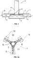
- Figure 1 shows a general profile view of the auxiliary floating system (1) of the invention, together with an offshore structure (2), which in this case comprises a foundation (3) and a tower or shaft (4).
- the auxiliary floating system (1) comprises at least a floating element (5) (specifically, in the example of figure 1 , two of said elements (5) are shown.)
- the auxiliary floating system (1) is coupled to the offshore structure (2) during the installation, the laying of the foundation, the anchoring or transport of the same.
- a provisional phase of the installation process of the offshore structure (2) is shown, wherein the same is afloat and partially submerged below the sea level (6).
- the floating elements (5) of the system (1) are connected to a coupling structure (7) which, preferably, is intended to surround the offshore structure (2), being arranged around the shaft (4) such that the points or regions of contact with the coupling structure (7) serve as a stabilization guide for the offshore structure (2), helping the same to maintain its verticality during the previously mentioned operations.
- the coupling structure (7) preferably forms a locking ring (8) (see, for example, the view shown in figure 2a or figure 2h ) around the shaft (4), which can be in a circular form, or have any other closed, curved or polygonal geometry.
- the coupling structure (7) provides a physical stop against variations in the position of verticality of the offshore structure (2), limiting the possible tilt that the same may experience (for example, due to the wind, swell, etc.) and helping said structure (2) maintain its stability, but by means of sliding contacts that allow for the free movement along a substantially vertical axis, which is a fundamental advantage in the operations of anchoring or ballasting the offshore structure (2) when the same is in the final location.
- the aforementioned free movement of the offshore structure (2) can be carried out by sliding, rolling, caterpillar tracks, or any known technique which allows for independent relative movement and which is sufficiently free between the guide elements (9) on the surface of the shaft (4).
- the guide elements (9) prevent and/or limit other relative movements between the auxiliary floating system (1) and the shaft (4), either by relative horizontal movement (preferably being equal to or less than 1 m), the relative rotation in the rock and/or pitch (preferably equal to or less than 10 degrees) and the relative rotation in the yaw (preferably less than 20 degrees).
- the offshore structure (2) comprises a foundation platform (3), and a shaft (4) with a plan dimension less than that of said foundation.
- the foundation (3) is preferably semi-submerged and the shaft (4) is completely emerged.
- the floating elements (5), also semi-submerged, are positioned at a sufficient distance from the axis of the shaft (4) so as not to hit the foundation (3) while it remains semi-submerged.
- the coupling structure (7) thus remains connected to the floating elements (5), emerged, and floating above the semi-submerged foundation (3), and in this way it does not interfere in the coupling of the auxiliary floating system (1) to the shaft (4).
- the auxiliary floating system (1) contributes to the stability of the offshore structure (2), but does not contribute to the buoyancy thereof, given that, as was previously explained, the relative vertical movement between the system (1) and the structure (2) is freed, and therefore the system (1) does not transmit any vertical force to the structure (2), which contributes in a relevant way to the buoyancy thereof. Therefore, said offshore structure (2) will mainly be a self-floating structure or have positive buoyancy, in other words it will not depend on the vertical forces that can be applied by the auxiliary floating system (1) in order to have said buoyancy. Put another way, in the absence of the floating system (1), the offshore floating structure (2) would have a reduced stability, but would not experience relevant changes to the floating depth thereof. Therefore, unlike other solutions in the prior art, the present invention does not require a connection in a vertical direction between the auxiliary means and the offshore structure to be installed, which provides a great operative advantage.
- securing means to prevent or limit relative vertical movement between the offshore structure (2) and the guide elements (9), such as rigid bars, cables of variable length or that are fixed, or other connection and/or securing means known in the art.
- these securing means are preferably provisional and the use thereof is limited, in all cases, to only one or some phases of the installation process, such as the tugboat transport of the assembly formed by said offshore structure (2) and the system (1).
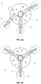
- Figures 2a-2e show an upper view of the different positions of the coupling structure (7) in a preferred embodiment of an auxiliary floating system (1) according to the present invention.
- Said embodiment shows a configuration based on three floating elements (5) connected to the coupling structure (7) and a plurality of guide elements (9) secured to the coupling structure (7) that make up a stabilization perimeter to house and couple to the offshore structure (2) (shown in figures 2f-2h ), surrounding the shaft (4) of said structure (2).
- the coupling structure (7) also acts as a joining structure for the different floating elements (5).
- the coupling structure (7) is made up of a lattice metal structure, as shown in figures 2a-2h .
- said coupling structure (7) comprises an opening and/or closing subsystem (10) to facilitate the placement and/or removal of the offshore structure (2) and, optionally, one or more actuators (11) for the folding and/or unfolding of the system (1), intended to apply the necessary forces between the different floating elements (5) of the system (1) to go from a folded configuration to an unfolded configuration (meaning in the coupling position with the offshore structure (2) and/or vice versa).
- Said actuators (11) may or may not have remote actuation.
- the actuators comprise telescopic, hydraulic cylinders, able to exert force by extending or retracting.
- said actuators (11) can comprise different types of means known in the art, such as mechanic, pneumatic or hydraulic actuators, cable actuated by means of winches or similar.
- the coupling structure (7) is preferably modular or adjustable in order to be able to adapt to offshore structures (2) and/or shafts (4) of different dimensions and/or characteristics.
- a module can be added or subtracted from the lattice arms of the coupling structure (7) in order to adjust the length thereof and, therefore, the distance thereof to the shaft (4).
- the position and/or dimension of the guide elements (9) can be changed or regulated, such that the same auxiliary floating system (1) can be used to install offshore structures (2) with shafts (4) of different diameters, or shafts (4) with a variable diameter.
- Figure 2a shows the auxiliary floating system (1) in the extended configuration thereof, unfolded and closed, just as it would act during the transport and/or installation of the offshore structure (2) (see, for example, figures 2f-2h ).
- figures 2b-2d show different steps of the folding method of said auxiliary floating system (1), wherein an articulated coupling structure (7) is shown, which allows a folded configuration to be adopted thereby enabling the coupling to and uncoupling from the shaft (4), facilitating the transport and/or collection thereof when it is not in operation.
- figure 2e shows the auxiliary floating system (1) in the folded configuration thereof, which can for example, be used for the transport the same to the port once the installation of said offshore structure (2) is finished.
- the floating elements (5) can also comprise a plurality of fenders (12) which are used to prevent impacts between said elements (5) during the transport and/or in the folded configuration thereof.
- the option of the coupling structure (7) being modular and/or adjustable allows the system to adapt to foundations (3) and/or shafts (4) of different dimensions or characteristics, thereby providing an advantage of additional application when compared to other systems of the state of the art.
- the auxiliary floating system (1) comprises three floating elements (5)
- the coupling structure (7) comprises three lattice arms, each one joined by one end to each floating element (5). This way, three modules or sub-assemblies are formed, each one made up of a floating element (5) and an arm of the coupling structure (7), which are joined to one another.
- each arm and floating element (5) assembly is self-balancing, in other words, each one of the sub-assemblies can float independently, maintaining the lattice arm in an essentially horizontal position.
- the floating element (5) can have an eccentric top slab, and/or an eccentric ballast as a counterweight, thereby compensating for the eccentricity of the lattice. Thanks to the previously explained points, when the auxiliary floating system (1) opens or closes to couple to or uncouple from the offshore structure (2), the coupling structure (7) is essentially maintained on the same horizontal plane.
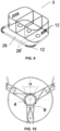
- figures 2f-2h show different phases of the coupling process of the system (1) of the invention to an offshore structure (2) that comprises a shaft (4) and a foundation (3).
- the modular coupling structure (7) comprises a support element (13) on the tower shaft (4), and one or more mobile elements (14) that close on said shaft (4).
- the mobile elements (14) comprise a part or all of the components of the closing subsystem (10), which allows for the complete coupling structure (7) to close on the offshore structure (2), carrying out, for example, the following steps:
- the opening and/or closing subsystem (10) can comprise one or more articulations (15) that allow for an essentially vertical rotation of a floating element (5) of the coupling structure (7) with respect to another floating element (5).
- the arrangement of floating elements (5) according to the embodiment shown in figures 2a-2h further has the advantage in that said elements (5) do not overlap, in the plan distribution thereof, with the plan distribution of the offshore structure (2) when the opening and/or closing subsystem (10) is closed on said offshore structure (2).
- said elements (5) do not overlap, in the plan distribution thereof, with the plan distribution of the offshore structure (2) when the opening and/or closing subsystem (10) is closed on said offshore structure (2).
- the plan position of the foundation (3) of the offshore structure (2) does not coincide with the corresponding position of the floating elements (5), regardless of the floating position said foundation (3) has.
- This provides great flexibility to the floating system (1) to adequately adapt to the different phases of the operations of transport, installation or maintenance of the offshore structure (2), which generally produce different anchoring levels (and which include, for example, both an emerged position of the foundation (3) of the offshore structure (2) and a submerged position of the same).
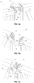
- the opening and/or closing subsystem (10) of the auxiliary floating system (1) has at least two cooperative closing elements (16, 17), optionally equipped with a plurality of fitting guides (18, 18', 18") intended to facilitate an appropriate orientation of the floating elements (5) of the coupling structure (7) during the closing operation of the floating system (1) on the offshore structure (2).
- the fitting guides (18, 18', 18") are advantageous for adapting the position of the coupling structure (7) in the presence of perturbations caused by the uneven levels of the sea level (6), (for example, due to the swell).
- opening/closing subsystem (10) it is possible to include one or more additional closing means, such as joints by means of bolts (20), bolted joints of approximation (21) or other means such as magnets, electromechanical locks, etc. are also able to be used in the sphere of the invention.
- additional closing means such as joints by means of bolts (20), bolted joints of approximation (21) or other means such as magnets, electromechanical locks, etc.
- the auxiliary floating system (1) can additionally comprise at least a longitudinal element secured by one of the ends thereof to the offshore structure (2) and by the other end thereof to said auxiliary floating system (1), the length of said longitudinal element being adjustable such that said connection can be maintained while the offshore structure (2) sinks, the relative position thereof varying with respect to the auxiliary floating system (1), which is maintained essentially at the same floating level on the surface.
- figure 4 represents a preferred embodiment wherein the offshore structure (2) to be installed comprises a telescopic offshore wind turbine tower formed by said telescopic modules (22, 22', 22") with a circular plan.
- the foundation (3) is semi-submerged during the transport thereof and the shaft (4) acts as a module or base section of said telescopic wind turbine tower.
- Figure 6 shows another stage of the method for the installation of the foundations (3) and/or offshore wind turbine towers, wherein one or more tugboats (23) are used to pull the auxiliary floating system (1) during the transport of the assembly to the final location thereof, and/or during the anchoring of the offshore structure (2) to the definitive situation thereof.
- one or more tugboats (23) are used to pull the auxiliary floating system (1) during the transport of the assembly to the final location thereof, and/or during the anchoring of the offshore structure (2) to the definitive situation thereof.
- the offshore structure (2) is partially anchored during the transportation thereof and the telescopic tower is partially raised.
- Figure 7 represents another preferred embodiment of the invention, wherein the offshore structure (2) to be installed comprises a shaft (4) with a polygonal section, such that it facilitates the installation of the auxiliary floating system (1), limiting or preventing the rotation capability of said offshore structure (2) with respect to the guide elements (9).
- the coupling structure (7) is formed by a lattice and comprises two rings (8) that surround the shaft (4) at two different heights, coinciding with the lower part and the upper part of said lattice.
- the guide elements (9) are distributed on the perimeter of both rings (8), thus being situated on two different levels and improving the efficiency of the system for limiting relative inclinations between the system (1) and the shaft (4) while at the same time reducing the fundamentally horizontal forces, which to said end are mutually transmitted through the guide elements (9).
- Figure 8c illustrates another phase of the method of installing foundations (100) and/or shafts (4) of offshore wind turbine towers, specifically the step of anchoring the offshore structure (2) at the definitive situation thereof on the seabed (24).
- the offshore structure (2) comprises several compartments (25) that form part of the foundation (3), wherein a differential control is carried out of the filling to facilitate the control of the inclinations of the assembly.
- three or more tugboats (not shown in figure 8c ) are used, which act on the system (1) in order to maintain the plan position of the assembly.
- the shaft (4) has a constant diameter, which facilitates the guiding operation, and the length thereof is such that the upper part of the same is emerged in an installed condition, such that the level of the top elevation of said shaft (4) is higher than the level at which at least part of the guide elements (9) comprised in the system are situated.
- the floating element (5) can comprise one or more lower gates (26') for regulating the ballast on the base of said floating element (5), situated in the underwater area (the part of the floating body that is submerged, in contact with the water) to allow and/or control the flow of water between the inside of said floating element (5) and the body of water in which it floats, as a means for adjusting the behavior, damping and natural frequency of the assembly.
- Said gates (26') preferably have an adjustable opening and/or remote actuation.
- the methods associated with the aforementioned operations can optionally include, a first stage wherein at least one of said gates is totally or partially open, which is equivalent to reducing the effective area of the floating element (5) that comprises it, and a second stage wherein said gate (26') closes with respect to the position of the first stage, which is equivalent to increasing the effective area of the floating element (5).
- the regulating gates (26') can be used to regulate the ballast level of the floating element (5).
- the regulating gates (26') are totally or partially open in phases in which the foundation (3) is in an emerged position.
- the adjustable gates (26') are closed (or at least more closed than in the emerged position of the foundation (3)).
- the floating element (5) can be manufacture using different materials known in the art, preferably concrete and/or metal materials.
- a mixed construction can also be used, manufacturing an inner part of concrete and the rest of the floating element (5) of steel.
- Techniques using precast concrete similar to those commonly used for the construction of precast containers can also be used.
- the configuration of floating elements (5) can also be modular, to be able to adjust the global size thereof.
- the pieces or modules that can be used to form said floating elements (5) can be different forms, the dimensions thereof preferably being suitable for containerization (no greater than those of a standard container) in order to facilitate the transport and reused thereof.
- Said modules can be joined to one another to make up a floating element (5) both at the base as well as above.
- the assembly formed by the floating elements (5) and the coupling structure (7) that couples to the offshore structure (2) is hydrodynamically self-stabilizing, in such a way that the distribution of mass of said floating elements (5) and of the coupling structure (7), and the corresponding floating center, is such that the floating elements (5) are balanced in an erected position when the opening and/or closing subsystem (10) is open (that is, with the uncoupling system (1) of the offshore structure (2)).
- this implies that, even when the subsystem (10) is open, the assembly of elements on each side of the articulations (15) will adopt a position with a depth, pitch and tilt essentially equal to those of the closed subsystem (10).
- figures 10 and 11 show different aspects of the same that are provided for illustrative purposes.
- Figure 10 shows how the guide elements (9) have a plan arrangement around the shaft (4), such that the maximum plan angle ( ⁇ ) formed by any pair of said guide elements (9) and the central axis of the shaft (4) is equal to or less than three radians.
- figure 11 shows guide elements (9), the elevation arrangement of which takes place on at least two levels, the difference in level between the highest level (27) and the lowest level (28) of said levels being equal to or greater than 1 m.
- H a given length
- figure 12 shows an embodiment of the invention based on a single floating element (5) connected to a coupling structure (7) intended to be secured to the offshore structure (2).
- Said embodiment of the system is especially indicated in maintenance operations of said structure (2), wherein, for example, the transport of the same is not necessary.
- the aforementioned maintenance operations will typically comprise the transport of the auxiliary floating system (1) to the location of the offshore structure (2) and the securing of the same by means of the operation of the opening and closing subsystem (10) of the coupling structure (7).
- land cranes will be able to be used, which are more economic than the offshore cranes, which is possible thanks to the fact that the coupling of the floating system (1) to the offshore structure (2) limits the movements of the former and facilitates the operation of the crane, even for work at tall heights, as is the case for example in the maintenance operations for wind turbines.
Claims (13)
- Kombination aus einer Offshore-Meereskonstruktion (2) und einem zusätzlichen schwimmenden System (1) für die Installation und/oder den Transport der Offshore-Meereskonstruktion (2), wobei die Offshore-Konstruktion (2) vorläufig oder endgültig selbstschwimmend ist und von der Art ist, die einen im Wesentlichen vertikalen Schaft (4) umfasst, wobei das zusätzliche schwimmende System (1) Folgendes umfasst:- eine Vielzahl von schwimmenden Elementen (5);- mindestens eine Kopplungsstruktur (7), die mit den schwimmenden Elementen (5) verbunden und zum Koppeln mit der Meereskonstruktion (2) um den Schaft (4) davon ausgebildet ist, wobei die Kopplungsstruktur (7) ein Öffnungs- und Schließ-Untersystem (10) umfasst, um das Platzieren davon auf der Offshore-Konstruktion (2) und/oder das Entfernen von dieser zu erleichtern, wobei das Öffnungs- und Schließ-Untersystem (10) ein oder mehrere Gelenke (15) umfasst, die eine Drehung der schwimmenden Elemente (5) um die Gelenke (15) in Bezug auf eine im Wesentlichen vertikale Achse ermöglichen; und wobei die Kopplungsstruktur (7) eine modulare oder gelenkige Struktur ist, die die schwimmenden Elemente (5) verbindet,- ein oder mehrere Führungselemente (9), die an der Kopplungsstruktur (7) gesichert sind, die eine oder mehrere Gleitkontaktflächen mit dem Schaft (4) bereitstellen;dadurch gekennzeichnet, dassdie Kopplungsstruktur (7) mindestens einen Ring (8) umfasst, der zum Umgeben des Schafts (4) der Offshore-Konstruktion (2) angepasst ist, und eine Vielzahl von Gitterarmen, die den Ring (8) und die schwimmenden Elemente (5) verbinden, wobei die Führungselemente (9) von dem Ring (8) umfasst sind und wobei die Länge der Gitterarme den Abstand zwischen den schwimmenden Elementen (5) und dem Schaft (4) festlegt;und dass das zusätzliche schwimmende System (1) so ausgebildet ist, dass, wenn die Kopplungsstruktur (7) mit der Offshore-Meereskonstruktion (2) um den vertikalen Schaft (4) davon gekoppelt ist:- die Kopplungsstruktur (7) eine im Wesentlichen freie vertikale Relativbewegung zwischen den schwimmenden Elementen (5) des zusätzlichen schwimmenden Systems (1) und dem Schaft (4) ermöglicht, so dass, wenn die Offshore-Konstruktion (2) sinkt, das zusätzliche schwimmende System (1) auf der Oberfläche im Wesentlichen auf dem gleichen Niveau verbleibt; und- die Kopplungsstruktur (7) andere Relativbewegungen zwischen dem zusätzlichen schwimmenden System (1) und dem Schaft (4) begrenzt und/oder verhindert, sowohl in der horizontalen Relativbewegung als auch in der relativen Drehung während des Rollens, Nickens oder Gierens.
- Kombination nach dem vorhergehenden Anspruch, die eine Vielzahl von Führungselementen (9) umfasst, und wobei die Führungselemente (9) eine Plananordnung um den Schaft (4) herum aufweisen, so dass der maximale Planwinkel (α), der von einem beliebigen Führungselement (4), dem benachbarten Führungselement (4) und der Mittelachse des Schafts (4) gebildet wird, gleich oder kleiner als drei Radiant ist.
- Kombination nach einem der vorhergehenden Ansprüche, die eine Vielzahl von Führungselementen (9) mit einer erhöhten Anordnung auf mindestens zwei Niveaus umfasst, wobei der Niveau-Unterschied zwischen dem höchsten Niveau (401) und dem niedrigsten Niveau (402) der Niveaus gleich oder größer als 1 m ist.
- Kombination nach einem der vorhergehenden Ansprüche zur Verwendung davon in Offshore-Strukturen (2), deren Schaft (4) einen transversalen Querschnitt mit einer im Wesentlichen polygonalen Außengeometrie aufweist, und mindestens drei Führungselemente (9) in Kontakt mit dem Schaft (4) in der Nähe der Scheitelpunkte der im Wesentlichen polygonalen Geometrie aufweist.
- Kombination nach einem der vorhergehenden Ansprüche, wobei das Öffnungs- und/oder Schließ-Untersystem (10) ein oder mehrere Gelenke (15) umfasst, die eine im Wesentlichen vertikale Drehung eines schwimmenden Elements (5) der Kopplungsstruktur (7) in Bezug auf ein anderes schwimmendes Element (5) ermöglichen.
- Kombination nach einem der vorhergehenden Ansprüche, wobei das Öffnungs- und/oder Schließ-Untersystem (10) des zusätzlichen schwimmenden Systems (1) mindestens zwei zusammenwirkende Schließelemente (16, 17) aufweist, die gegebenenfalls mit einer Vielzahl von Anpassungsführungen (18, 18', 18") ausgestattet sind, die angepasst sind, um die Position der schwimmenden Elemente (5) der Kopplungsstruktur (7) während des Schließbetriebs des schwimmenden Systems (1) an der Offshore-Konstruktion (2) zu orientieren.
- Kombination nach einem der vorhergehenden Ansprüche, wobei das zusätzliche schwimmende System (1) mindestens ein Längselement umfasst, das mit einem seiner Enden an der Offshore-Konstruktion (2) und mit dem anderen Ende an dem zusätzlichen schwimmenden System (1) gesichert ist, wobei die Länge des Längselements so anpassbar ist, dass die Verbindung aufrechterhalten werden kann, während die Offshore-Konstruktion (2) sinkt, wobei die relative Position davon in Bezug auf das zusätzliche schwimmende System (1) variiert, das im Wesentlichen auf dem gleichen Schwimmniveau auf der Fläche gehalten wird.
- Kombination nach einem der vorhergehenden Ansprüche, wobei die Offshore-Konstruktion (2) ein Fundament (3) aufweist, und wobei mindestens ein schwimmendes Element (5) des Systems eine Tiefe (29) und einen Freibord (30) aufweist, die beide gleich oder größer als eine vorgegebene Länge (H) sind, deren Wert im Wesentlichen der Gleichung H=R·sin(α') entspricht, wobei (R) der Abstand von der Mitte jedes schwimmenden Elements (5) zur Längsachse des Schafts (4) ist, und (α') der maximale Neigungswinkel des Fundaments (3) der Offshore-Konstruktion (2) ist, der während der Installation und/oder des Transports davon zulässig ist.
- Kombination nach einem der vorhergehenden Ansprüche, die Hebemittel umfasst, die für das Aufstellen und/oder Entfernen von Ausrüstung und/oder Personal auf oder von der Offshore-Konstruktion (2) geeignet sind.
- Verfahren zur Installation und/oder zum Transport einer Offshore-Meereskonstruktion (2), wobei die Offshore-Konstruktion (2) von der Art ist, die einen im Wesentlichen vertikalen Schaft (4) aufweist, dadurch gekennzeichnet, dass es die Verwendung einer Kombination aus der Offshore-Meereskonstruktion (2) und einem zusätzlichen schwimmenden System (1) nach einem der vorhergehenden Ansprüche umfasst und wobei mindestens die folgenden Schritte in jeder technisch möglichen Reihenfolge durchgeführt werden:a) Koppeln des zusätzlichen schwimmenden Systems (1) um die Offshore-Konstruktion (2);b) Verankern der Offshore-Konstruktion (2) in ihrer endgültigen Tiefe davon, während das zusätzliche schwimmende System (1) im Wesentlichen auf dem gleichen Schwimmniveau an der Oberfläche gehalten wird; undc) Entfernen des zusätzlichen schwimmenden Systems (1) von der Offshore-Konstruktion (2).
- Verfahren nach dem vorhergehenden Anspruch, das einen der folgenden Schritte umfasst:- Transportieren des zusätzlichen schwimmenden Systems (1) und/oder der Offshore-Konstruktion (2) zu dem endgültigen Offshore-Ort davon, vor oder nach Schritt a);- Verbinden von Schleppern (23) mit dem zusätzlichen schwimmenden System (1) während eines oder mehrerer der Schritte davon.
- Verfahren nach einem der Ansprüche 10-11, angewandt auf eine Offshore-Konstruktion (2), die aus teleskopischen Turm-Modulen (22, 22', 22") besteht, das zusätzlich das teilweise oder vollständige Anheben der Module (22, 22', 22") während eines oder mehrerer Schritte davon umfasst.
- Verfahren nach einem der Ansprüche 10-12, wobei die Offshore-Konstruktion (2) ein Fundament (3) umfasst; wobei eines oder mehrere der schwimmenden Elemente (5) ein oder mehrere Tore (26') zum Regulieren des Ballasts auf der Basis der schwimmenden Elemente (5) umfasst; und wobei das Verfahren eine erste Stufe umfasst, in der die regulierenden Tore (26') vollständig oder teilweise geöffnet sind, wobei sich das Fundament (3) in einer aufgetauchten Position befindet; und eine zweite Stufe, in der die regulierenden Tore (26') vollständig geschlossen oder geschlossener als in der ersten Stufe sind, wobei sich das Fundament (3) in einer eingetauchten Position befindet.
Applications Claiming Priority (2)
| Application Number | Priority Date | Filing Date | Title |
|---|---|---|---|
| ES201630627A ES2642177B1 (es) | 2016-05-13 | 2016-05-13 | Sistema flotante auxiliar para la instalación y/o el transporte de estructuras marinas y procedimiento que comprende dicho sistema. |
| PCT/ES2017/070306 WO2017194813A1 (es) | 2016-05-13 | 2017-05-12 | Sistema flotante auxiliar para la instalación y/o el transporte de estructuras marinas y procedimiento que comprende dicho sistema |
Publications (4)
| Publication Number | Publication Date |
|---|---|
| EP3456960A1 EP3456960A1 (de) | 2019-03-20 |
| EP3456960A4 EP3456960A4 (de) | 2019-12-11 |
| EP3456960C0 EP3456960C0 (de) | 2023-11-15 |
| EP3456960B1 true EP3456960B1 (de) | 2023-11-15 |
Family
ID=60266361
Family Applications (1)
| Application Number | Title | Priority Date | Filing Date |
|---|---|---|---|
| EP17795670.3A Active EP3456960B1 (de) | 2016-05-13 | 2017-05-12 | Zusätzliches schwimmendes system zur installation und/oder zum transport von meereskonstruktionen und verfahren mit dem besagten system |
Country Status (6)
| Country | Link |
|---|---|
| US (1) | US10773777B2 (de) |
| EP (1) | EP3456960B1 (de) |
| JP (1) | JP7054210B2 (de) |
| CN (1) | CN109790823B (de) |
| ES (1) | ES2642177B1 (de) |
| WO (1) | WO2017194813A1 (de) |
Families Citing this family (9)
| Publication number | Priority date | Publication date | Assignee | Title |
|---|---|---|---|---|
| ES2785802B2 (es) * | 2019-04-05 | 2021-05-19 | Esteyco S A | Procedimiento de instalacion de un aerogenerador de torre mar adentro |
| ES2796978B2 (es) * | 2019-05-31 | 2022-07-13 | Esteyco S A | Procedimiento para el mantenimiento de torres eolicas mediante sistemas flotantes auxiliares |
| CN110332462B (zh) * | 2019-07-10 | 2021-07-27 | 深圳赛诺凡尔纳能源有限公司 | 一种水下压缩空气储能发电装置 |
| KR102247619B1 (ko) * | 2020-02-11 | 2021-05-03 | 한국전력기술 주식회사 | 부유식풍력발전기의 상부타워를 이송하기 위한 운송장치 |
| WO2021255509A1 (en) * | 2020-06-19 | 2021-12-23 | Zhiyong Yang | A floating platform with canted columns |
| CN112339922B (zh) * | 2020-10-27 | 2021-08-24 | 华能(浙江)能源开发有限公司清洁能源分公司 | 海上风电施工平台 |
| CN112377372B (zh) * | 2020-11-03 | 2022-05-17 | 上海电气风电集团股份有限公司 | 海上漂浮式风机基础、海上风机及海上风机的安装方法 |
| CN112761894B (zh) * | 2021-02-02 | 2022-01-18 | 蓬莱大金海洋重工有限公司 | 一种海上风力发电系统及其方法 |
| CN115092330B (zh) * | 2022-07-20 | 2023-05-26 | 长江勘测规划设计研究有限责任公司 | 海上风电筒型基础全自由度限位的浮运固定装置 |
Family Cites Families (22)
| Publication number | Priority date | Publication date | Assignee | Title |
|---|---|---|---|---|
| FR2574367A1 (fr) * | 1984-12-07 | 1986-06-13 | Vic Offshore Sarl | Structure marine a ancrage tendu vertical |
| FI107184B (fi) * | 1999-11-11 | 2001-06-15 | Asko Fagerstroem | Menetelmä ja järjestelmä offshore-tuulivoimalan asentamiseksi merelle ja/tai noutamiseksi mereltä, ja offshore-tuulivoimala |
| JP2001241374A (ja) * | 2000-02-28 | 2001-09-07 | Colcose:Kk | 水上用風力発電機設置方法及びその装置 |
| JP2002285951A (ja) * | 2001-03-23 | 2002-10-03 | Hitachi Zosen Corp | 洋上風力発電の浮体式基礎構造物 |
| ITBA20020047A1 (it) * | 2002-12-17 | 2004-06-18 | Enertec Aktiegesellschaft Ag | Metodo di realizzazione di una piattaforma sommergibile a spinta bloccata per la produzione di energia elettrica dal vento in mare aperto e di prodotti di maricoltura |
| EP2036815B1 (de) * | 2007-09-12 | 2013-05-01 | WeserWind GmbH | Verfahren zur Installation und Deinstallation einer Gründungsstruktur sowie Gründungsstruktur und Auftriebskörper |
| FR2932771B1 (fr) * | 2008-06-20 | 2010-06-04 | Technip France | Structure de transport et d'installation en mer d'au moins une eolienne ou hydrolienne et procedes de transport et d'installation en mer d'au moins une eolienne ou hydrolienne. |
| DE102008046359A1 (de) * | 2008-09-09 | 2010-03-11 | Ed. Züblin Ag | Vorrichtung zum Transport und Installieren von zumindest eine Flachgründung umfassende Anordnung einer Offshore-Windenergieanlage sowie Verfahren zum Transport und zur Installation einer solchen Flachgründung mit Mast |
| CN102079476A (zh) * | 2009-11-27 | 2011-06-01 | 三一电气有限责任公司 | 一种风机抱举装置及移动式水上作业平台 |
| JP2011207446A (ja) * | 2010-03-30 | 2011-10-20 | Mitsui Eng & Shipbuild Co Ltd | 支援用浮体、支援用浮体を用いた浮体の曳航方法及び支援用浮体を用いた浮体の設置方法 |
| GB2481258A (en) * | 2010-06-19 | 2011-12-21 | Peter Ronald Chambers | A submersible dynamic floatation tank mountable to a base of an offshore wind turbine assembly |
| JP5736133B2 (ja) * | 2010-07-23 | 2015-06-17 | ジャパンマリンユナイテッド株式会社 | 浮体構造物作業システム、作業船及び浮体構造物作業方法 |
| NO20111329A1 (no) * | 2011-09-29 | 2012-10-08 | Windel As | Flytende vindmølle |
| CN102506012A (zh) * | 2011-11-09 | 2012-06-20 | 汪砚秋 | 锚泊半潜连体底座海上风力发电机组 |
| WO2013137744A1 (en) * | 2012-03-13 | 2013-09-19 | Ntnu Technology Transfer As | Floating wind turbine with wave energy converter |
| GB2511272A (en) * | 2012-03-13 | 2014-09-03 | Norges Teknisk Naturvitenskapelige Uni | A wind turbine |
| NL2009763C2 (en) * | 2012-11-06 | 2014-05-08 | Mecal Wind Turbine Design B V | Floatable transportation and installation structure for transportation and installation of a floating wind turbine, a floating wind turbine and method for transportation and installation of the same. |
| CN103803024A (zh) * | 2014-01-31 | 2014-05-21 | 中交一航局第二工程有限公司 | 半浮式海上风力发电机组整体运输安装一体船及施工方法 |
| CN103925172B (zh) * | 2014-04-08 | 2017-05-17 | 上海交通大学 | 张力腿式海上浮动式风力机的整体安装方法 |
| EP3153399A4 (de) * | 2014-05-27 | 2018-05-30 | Esteyco S.A.P. | Schwimmender unterbau für eine windkraftanlage und installationsverfahren dafür |
| BE1022390B1 (nl) * | 2014-10-20 | 2016-03-21 | Geosea Nv | Werkwijze voor het met een vaartuig over water vervoeren van een bouwwerk met drijfvermogen, en in de werkwijze toegepast vaartuig |
| CN105484934A (zh) * | 2016-02-14 | 2016-04-13 | 河海大学 | 一种可采集波浪能的海上漂浮式风力发电平台及集聚群 |
-
2016
- 2016-05-13 ES ES201630627A patent/ES2642177B1/es active Active
-
2017
- 2017-05-12 WO PCT/ES2017/070306 patent/WO2017194813A1/es unknown
- 2017-05-12 JP JP2018559863A patent/JP7054210B2/ja active Active
- 2017-05-12 US US16/301,264 patent/US10773777B2/en active Active
- 2017-05-12 CN CN201780043742.4A patent/CN109790823B/zh active Active
- 2017-05-12 EP EP17795670.3A patent/EP3456960B1/de active Active
Also Published As
| Publication number | Publication date |
|---|---|
| CN109790823A (zh) | 2019-05-21 |
| ES2642177B1 (es) | 2018-08-29 |
| WO2017194813A1 (es) | 2017-11-16 |
| EP3456960A4 (de) | 2019-12-11 |
| CN109790823B (zh) | 2021-07-09 |
| EP3456960C0 (de) | 2023-11-15 |
| US20190135385A1 (en) | 2019-05-09 |
| JP7054210B2 (ja) | 2022-04-13 |
| ES2642177A1 (es) | 2017-11-15 |
| EP3456960A1 (de) | 2019-03-20 |
| US10773777B2 (en) | 2020-09-15 |
| JP2019518153A (ja) | 2019-06-27 |
Similar Documents
| Publication | Publication Date | Title |
|---|---|---|
| EP3456960B1 (de) | Zusätzliches schwimmendes system zur installation und/oder zum transport von meereskonstruktionen und verfahren mit dem besagten system | |
| EP1986947B1 (de) | Installation von offshore-strukturen | |
| CN102124214B (zh) | 供在离岸风力农场工业中使用的支撑结构 | |
| US8864419B2 (en) | Foundation support system for an offshore wind energy convertor, corresponding to an offshore wind power generating facility | |
| US20220227465A1 (en) | Method for the Maintenance of Wind Turbine Towers by means of Auxiliary Floating Systems | |
| JP2011112045A (ja) | 風力タービン固定および吊り上げ装置、および水上移動式作業プラットフォーム | |
| CN112135772B (zh) | 一种用于海上部署的风力涡轮机 | |
| US20220234697A1 (en) | A floating structure and method of installation | |
| GB2495830A (en) | Transition piece for an offshore wind turbine with attached walkway on the leeward side. | |
| EP3693513B1 (de) | Struktur und verfahren zur ausserbetriebnahme einer offshore-plattform | |
| TWI702327B (zh) | 海港設施以及在該海港設施停泊浮體的方法 | |
| EP3532678B1 (de) | Hafenanlage und verfahren zum verankern eines schwimmenden körpers in einer hafenanlage | |
| US20190264655A1 (en) | Conversion of moveable offshore drilling platforms to a wind turbine installation unit | |
| WO2023194711A1 (en) | Improvements in and relating to assembling a structure | |
| GB2619788A (en) | Improvements in and relating to assembling a structure | |
| WO2024003576A1 (en) | Improvements in and relating to assembling a structure | |
| WO2023170224A1 (en) | Marine structure and method |
Legal Events
| Date | Code | Title | Description |
|---|---|---|---|
| STAA | Information on the status of an ep patent application or granted ep patent |
Free format text: STATUS: THE INTERNATIONAL PUBLICATION HAS BEEN MADE |
|
| PUAI | Public reference made under article 153(3) epc to a published international application that has entered the european phase |
Free format text: ORIGINAL CODE: 0009012 |
|
| STAA | Information on the status of an ep patent application or granted ep patent |
Free format text: STATUS: REQUEST FOR EXAMINATION WAS MADE |
|
| 17P | Request for examination filed |
Effective date: 20181205 |
|
| AK | Designated contracting states |
Kind code of ref document: A1 Designated state(s): AL AT BE BG CH CY CZ DE DK EE ES FI FR GB GR HR HU IE IS IT LI LT LU LV MC MK MT NL NO PL PT RO RS SE SI SK SM TR |
|
| AX | Request for extension of the european patent |
Extension state: BA ME |
|
| STAA | Information on the status of an ep patent application or granted ep patent |
Free format text: STATUS: REQUEST FOR EXAMINATION WAS MADE |
|
| DAV | Request for validation of the european patent (deleted) | ||
| DAX | Request for extension of the european patent (deleted) | ||
| RAP1 | Party data changed (applicant data changed or rights of an application transferred) |
Owner name: ESTEYCO SA |
|
| A4 | Supplementary search report drawn up and despatched |
Effective date: 20191108 |
|
| RIC1 | Information provided on ipc code assigned before grant |
Ipc: B63B 1/14 20060101ALI20191104BHEP Ipc: B63B 35/00 20060101ALI20191104BHEP Ipc: B63B 35/44 20060101ALI20191104BHEP Ipc: F03D 13/25 20160101AFI20191104BHEP |
|
| STAA | Information on the status of an ep patent application or granted ep patent |
Free format text: STATUS: EXAMINATION IS IN PROGRESS |
|
| 17Q | First examination report despatched |
Effective date: 20211111 |
|
| RAP3 | Party data changed (applicant data changed or rights of an application transferred) |
Owner name: ESTEYCO SA |
|
| GRAP | Despatch of communication of intention to grant a patent |
Free format text: ORIGINAL CODE: EPIDOSNIGR1 |
|
| STAA | Information on the status of an ep patent application or granted ep patent |
Free format text: STATUS: GRANT OF PATENT IS INTENDED |
|
| INTG | Intention to grant announced |
Effective date: 20230612 |
|
| GRAS | Grant fee paid |
Free format text: ORIGINAL CODE: EPIDOSNIGR3 |
|
| GRAA | (expected) grant |
Free format text: ORIGINAL CODE: 0009210 |
|
| STAA | Information on the status of an ep patent application or granted ep patent |
Free format text: STATUS: THE PATENT HAS BEEN GRANTED |
|
| AK | Designated contracting states |
Kind code of ref document: B1 Designated state(s): AL AT BE BG CH CY CZ DE DK EE ES FI FR GB GR HR HU IE IS IT LI LT LU LV MC MK MT NL NO PL PT RO RS SE SI SK SM TR |
|
| REG | Reference to a national code |
Ref country code: CH Ref legal event code: EP Ref country code: GB Ref legal event code: FG4D |
|
| REG | Reference to a national code |
Ref country code: DE Ref legal event code: R096 Ref document number: 602017076553 Country of ref document: DE |
|
| REG | Reference to a national code |
Ref country code: IE Ref legal event code: FG4D |
|
| REG | Reference to a national code |
Ref country code: NO Ref legal event code: T2 Effective date: 20231115 |
|
| U01 | Request for unitary effect filed |
Effective date: 20231205 |
|
| U07 | Unitary effect registered |
Designated state(s): AT BE BG DE DK EE FI FR IT LT LU LV MT NL PT SE SI Effective date: 20231214 |
|
| PG25 | Lapsed in a contracting state [announced via postgrant information from national office to epo] |
Ref country code: GR Free format text: LAPSE BECAUSE OF FAILURE TO SUBMIT A TRANSLATION OF THE DESCRIPTION OR TO PAY THE FEE WITHIN THE PRESCRIBED TIME-LIMIT Effective date: 20240216 |
|
| PG25 | Lapsed in a contracting state [announced via postgrant information from national office to epo] |
Ref country code: IS Free format text: LAPSE BECAUSE OF FAILURE TO SUBMIT A TRANSLATION OF THE DESCRIPTION OR TO PAY THE FEE WITHIN THE PRESCRIBED TIME-LIMIT Effective date: 20240315 |
|
| PG25 | Lapsed in a contracting state [announced via postgrant information from national office to epo] |
Ref country code: ES Free format text: LAPSE BECAUSE OF FAILURE TO SUBMIT A TRANSLATION OF THE DESCRIPTION OR TO PAY THE FEE WITHIN THE PRESCRIBED TIME-LIMIT Effective date: 20231115 |
|
| PG25 | Lapsed in a contracting state [announced via postgrant information from national office to epo] |
Ref country code: IS Free format text: LAPSE BECAUSE OF FAILURE TO SUBMIT A TRANSLATION OF THE DESCRIPTION OR TO PAY THE FEE WITHIN THE PRESCRIBED TIME-LIMIT Effective date: 20240315 Ref country code: GR Free format text: LAPSE BECAUSE OF FAILURE TO SUBMIT A TRANSLATION OF THE DESCRIPTION OR TO PAY THE FEE WITHIN THE PRESCRIBED TIME-LIMIT Effective date: 20240216 Ref country code: ES Free format text: LAPSE BECAUSE OF FAILURE TO SUBMIT A TRANSLATION OF THE DESCRIPTION OR TO PAY THE FEE WITHIN THE PRESCRIBED TIME-LIMIT Effective date: 20231115 |
|
| U20 | Renewal fee paid [unitary effect] |
Year of fee payment: 8 Effective date: 20240325 |