EP3456910A1 - Sliding door arrangement - Google Patents
Sliding door arrangement Download PDFInfo
- Publication number
- EP3456910A1 EP3456910A1 EP17191761.0A EP17191761A EP3456910A1 EP 3456910 A1 EP3456910 A1 EP 3456910A1 EP 17191761 A EP17191761 A EP 17191761A EP 3456910 A1 EP3456910 A1 EP 3456910A1
- Authority
- EP
- European Patent Office
- Prior art keywords
- belt
- sliding door
- frame
- door arrangement
- shoulder
- Prior art date
- Legal status (The legal status is an assumption and is not a legal conclusion. Google has not performed a legal analysis and makes no representation as to the accuracy of the status listed.)
- Withdrawn
Links
- 229920001971 elastomer Polymers 0.000 description 3
- 239000000806 elastomer Substances 0.000 description 2
- 239000002131 composite material Substances 0.000 description 1
- 230000001419 dependent effect Effects 0.000 description 1
- 238000009434 installation Methods 0.000 description 1
- 230000007257 malfunction Effects 0.000 description 1
- 239000002184 metal Substances 0.000 description 1
- 238000011179 visual inspection Methods 0.000 description 1
Images


Classifications
-
- E—FIXED CONSTRUCTIONS
- E05—LOCKS; KEYS; WINDOW OR DOOR FITTINGS; SAFES
- E05F—DEVICES FOR MOVING WINGS INTO OPEN OR CLOSED POSITION; CHECKS FOR WINGS; WING FITTINGS NOT OTHERWISE PROVIDED FOR, CONCERNED WITH THE FUNCTIONING OF THE WING
- E05F15/00—Power-operated mechanisms for wings
- E05F15/60—Power-operated mechanisms for wings using electrical actuators
- E05F15/603—Power-operated mechanisms for wings using electrical actuators using rotary electromotors
- E05F15/632—Power-operated mechanisms for wings using electrical actuators using rotary electromotors for horizontally-sliding wings
- E05F15/643—Power-operated mechanisms for wings using electrical actuators using rotary electromotors for horizontally-sliding wings operated by flexible elongated pulling elements, e.g. belts, chains or cables
-
- E—FIXED CONSTRUCTIONS
- E05—LOCKS; KEYS; WINDOW OR DOOR FITTINGS; SAFES
- E05Y—INDEXING SCHEME ASSOCIATED WITH SUBCLASSES E05D AND E05F, RELATING TO CONSTRUCTION ELEMENTS, ELECTRIC CONTROL, POWER SUPPLY, POWER SIGNAL OR TRANSMISSION, USER INTERFACES, MOUNTING OR COUPLING, DETAILS, ACCESSORIES, AUXILIARY OPERATIONS NOT OTHERWISE PROVIDED FOR, APPLICATION THEREOF
- E05Y2201/00—Constructional elements; Accessories therefor
- E05Y2201/60—Suspension or transmission members; Accessories therefor
- E05Y2201/622—Suspension or transmission members elements
- E05Y2201/658—Members cooperating with flexible elongated pulling elements
- E05Y2201/672—Tensioners, tension sensors
Definitions
- This invention relates to a sliding door arrangement.
- a sliding door arrangement frequently comprises a motor, a door, a belt, a pulley and a belt return bracket.
- a correct belt tension is crucial for a smooth operation of sliding doors. Over tightening of the belt increases wear and under tightening causes operational errors and increases callouts. Furthermore, commonly used belts are known to stretch over time, and therefore, tightening of the belt is required periodically.
- a common way of setting the correct belt tension is to use a belt return bracket or a belt return pulley.
- the belt is tightened by tightening screws in the bracket with a separate tool and the correct tension is confirmed with a suitable tool or by visual inspection. Therefore, the tensioning of the belt greatly relies on a serviceman's experience and skill level.
- An object of the present invention is to overcome the above-mentioned drawbacks and to provide a sliding door arrangement with a belt return bracket having a belt tensioning mechanism. This object is achieved with a sliding door arrangement according to independent claim 1.
- a belt tensioning mechanism comprising a spring element with a predetermined force ensures that a correct, predetermined tension is applied during the operation despite stretching of the belt.
- Figure 1 illustrates the overall operation of a sliding door arrangement.
- a common way of applying a sliding door system is to have a door 1 attached to a toothed belt 2, which is driven by a motor 3 via a belt pulley 17 for moving the door 1 between a closed position 1-1 and an open position 1-2.
- the motor is an electric motor.
- the arrangement also comprises a belt return bracket 4 to ensure a correct tension in the belt 2. Setting a correct belt tension is crucial in order to avoid excessive callouts due to wear or malfunction caused by a stretched belt.
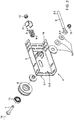
- FIG 2 is an exploded view of the belt return bracket illustrated in Figure 1 .
- the belt return bracket comprises a frame 5, a pulley 6, a pin 7, a rod 8, a spring element 9, a first fixed shoulder 10, a second free-moving shoulder 11, a first fastening element 12, a second fastening element 15, a bearing 13 and flanges 14.
- the pulley 6 is arranged against a first surface of the frame 5-1 with the pin 7 projecting through an elongated hole in the frame 5.
- the pulley 6 is further arranged to revolve around a rotation axis 16 and to engage with the belt 2.
- the belt is frequently made of rubber but can also be made out of, for example, an elastomer or a composite material.
- a belt tensioning mechanism is arranged against a second surface of the frame 5-2 for moving the position of the pulley 6 with relation to the frame 5.
- the belt tensioning mechanism comprises the rod 8 connected to the pin 7 from its first end 8-1 and a fastener attaching a first end of the spring element 9-1 to a second end of the rod 8-2 and a second end of the spring element 9-2 to the frame 5.
- the fastener further comprises the first shoulder 10 fixedly attached to the frame 5 and the second shoulder 11 attached to the rod 8 so that the spring element 9 is arranged between the first shoulder 10 and the second shoulder 11.
- the spring force from the spring element 9 is acting in a direction opposite to the tension force from the belt 2.
- the predetermined spring force ensures that a correct tension is applied to the belt at all times during operation and the need for periodical belt tightening is removed.
- the spring element is utilized not only once during installation of the sliding door arrangement but continuously over the lifetime of the arrangement.
- the second end of the rod 8-2 is threaded and further comprises a first fastening element 12 rotatably attached on the threads of the rod 8.
- the first fastening element 12 is arranged to enable the adjustment of the distance between the first shoulder 10 and the second shoulder 11, and therefore, the tension of the spring element 9 and the belt 2. This is advantageous, as the belt can be tightened using a simple tool, e.g. a wrench.
- the assembled belt return bracket of Figures 1 and 2 is illustrated in Figures 3a and 3b.
- Figure 3a illustrates the first surface of the frame 5-1
- Figure 3b illustrates the second surface of the frame 5-2.
- the directions of spring tension 18 and belt tension 19 are also illustrated.
- the second shoulder 11 includes a projection parallel to the first shoulder and at least one projection protruding towards the first shoulder 10.
- the purpose of the at least one protruding projection of the second shoulder 11 is to, upon tightening of the belt, make contact with the first shoulder 10 if excessive tightening is applied and thus act as a stopper to prevent over tensioning.
- the second shoulder 11 is suitably designed to include two protruding projections resulting in a u-shaped profile.
- a spring element for maintaining a correct tension at all times during operation in combination with a stopper to prevent over tensioning eliminates the need for having a separate tool for belt tightening or relying on serviceman's expertise to set the correct tension.
- the spring element 9 is preferably arranged to surround the rod 8 in the second end of the rod 8-2, as illustrated in Figure 3 .
- the spring element 9 is preferably a metal spring but it may also be, for example, a block of elastomer or a hydraulic spring. In another embodiment of the invention the spring element 9 could be positioned beside the rod 8 surrounding a second rod fixedly attached to the first shoulder 10 and movably attached to the second shoulder 11.
Landscapes
- Power-Operated Mechanisms For Wings (AREA)
Abstract
A sliding door arrangement, comprising a belt return bracket (4) a frame (5),
a pulley (6) which is arranged to engage with a belt (2), and rotatably attached to the frame (5) for rotation around a rotation axis (16). In addition the sliding door mechanism comprises a belt tensioning mechanism for moving the position of the pulley (4) in relation to the frame (5). The belt tensioning mechanism further comprises a spring element (9) arranged to move the position of the pulley (4) by a spring force and maintaining a predetermined belt tension. This is advantageous as the predetermined spring force ensures that a correct tension is applied to the belt at all times during operation.
Description
- This invention relates to a sliding door arrangement.
- Automated, sliding doors are used in a wide variety of applications, such as building doorways. A sliding door arrangement frequently comprises a motor, a door, a belt, a pulley and a belt return bracket. A correct belt tension is crucial for a smooth operation of sliding doors. Over tightening of the belt increases wear and under tightening causes operational errors and increases callouts. Furthermore, commonly used belts are known to stretch over time, and therefore, tightening of the belt is required periodically.
- A common way of setting the correct belt tension is to use a belt return bracket or a belt return pulley. The belt is tightened by tightening screws in the bracket with a separate tool and the correct tension is confirmed with a suitable tool or by visual inspection. Therefore, the tensioning of the belt greatly relies on a serviceman's experience and skill level.
- Due to the above-mentioned drawbacks, prior art sliding door arrangements are prone to callouts and a separate tool or special skills are required to perform belt tightening.
- An object of the present invention is to overcome the above-mentioned drawbacks and to provide a sliding door arrangement with a belt return bracket having a belt tensioning mechanism. This object is achieved with a sliding door arrangement according to
independent claim 1. - A belt tensioning mechanism comprising a spring element with a predetermined force ensures that a correct, predetermined tension is applied during the operation despite stretching of the belt. Preferred embodiments of the invention are disclosed in the dependent claims.
- In the following, the present invention will be described in closer detail by way of example and with reference to attached drawings, in which
-
Figure 1 illustrates the overall operation of a sliding door arrangement. -
Figure 2 illustrates parts of a belt return bracket, and -
Figure 3a and 3b illustrate the first and second surface in the belt return bracket assembly, respectively. -
Figure 1 illustrates the overall operation of a sliding door arrangement. As illustrated inFigure 1 , a common way of applying a sliding door system is to have adoor 1 attached to atoothed belt 2, which is driven by amotor 3 via abelt pulley 17 for moving thedoor 1 between a closed position 1-1 and an open position 1-2. In one embodiment of the present invention, the motor is an electric motor. The arrangement also comprises abelt return bracket 4 to ensure a correct tension in thebelt 2. Setting a correct belt tension is crucial in order to avoid excessive callouts due to wear or malfunction caused by a stretched belt. -
Figure 2 is an exploded view of the belt return bracket illustrated inFigure 1 . The belt return bracket comprises aframe 5, apulley 6, apin 7, arod 8, aspring element 9, a first fixedshoulder 10, a second free-movingshoulder 11, afirst fastening element 12, asecond fastening element 15, abearing 13 andflanges 14. In a preferred embodiment of the invention, thepulley 6 is arranged against a first surface of the frame 5-1 with thepin 7 projecting through an elongated hole in theframe 5. Thepulley 6 is further arranged to revolve around arotation axis 16 and to engage with thebelt 2. The belt is frequently made of rubber but can also be made out of, for example, an elastomer or a composite material. - In order to set and maintain a correct operating belt tension, a belt tensioning mechanism is arranged against a second surface of the frame 5-2 for moving the position of the
pulley 6 with relation to theframe 5. The belt tensioning mechanism comprises therod 8 connected to thepin 7 from its first end 8-1 and a fastener attaching a first end of the spring element 9-1 to a second end of the rod 8-2 and a second end of the spring element 9-2 to theframe 5. - The fastener further comprises the
first shoulder 10 fixedly attached to theframe 5 and thesecond shoulder 11 attached to therod 8 so that thespring element 9 is arranged between thefirst shoulder 10 and thesecond shoulder 11. In such an arrangement, the spring force from thespring element 9 is acting in a direction opposite to the tension force from thebelt 2. This is advantageous as the predetermined spring force ensures that a correct tension is applied to the belt at all times during operation and the need for periodical belt tightening is removed. In other words, the spring element is utilized not only once during installation of the sliding door arrangement but continuously over the lifetime of the arrangement. - In a preferred embodiment of the invention, the second end of the rod 8-2 is threaded and further comprises a
first fastening element 12 rotatably attached on the threads of therod 8. Thefirst fastening element 12 is arranged to enable the adjustment of the distance between thefirst shoulder 10 and thesecond shoulder 11, and therefore, the tension of thespring element 9 and thebelt 2. This is advantageous, as the belt can be tightened using a simple tool, e.g. a wrench. - The assembled belt return bracket of
Figures 1 and2 is illustrated inFigures 3a and 3b. Figure 3a illustrates the first surface of the frame 5-1 andFigure 3b illustrates the second surface of the frame 5-2. The directions ofspring tension 18 andbelt tension 19 are also illustrated. In one embodiment of the invention, thesecond shoulder 11 includes a projection parallel to the first shoulder and at least one projection protruding towards thefirst shoulder 10. The purpose of the at least one protruding projection of thesecond shoulder 11 is to, upon tightening of the belt, make contact with thefirst shoulder 10 if excessive tightening is applied and thus act as a stopper to prevent over tensioning. In a preferred embodiment of the invention, thesecond shoulder 11 is suitably designed to include two protruding projections resulting in a u-shaped profile. Other profiles, such as a c-shape profile, are possible as well. A spring element for maintaining a correct tension at all times during operation in combination with a stopper to prevent over tensioning eliminates the need for having a separate tool for belt tightening or relying on serviceman's expertise to set the correct tension. - The
spring element 9 is preferably arranged to surround therod 8 in the second end of the rod 8-2, as illustrated inFigure 3 . Thespring element 9 is preferably a metal spring but it may also be, for example, a block of elastomer or a hydraulic spring. In another embodiment of the invention thespring element 9 could be positioned beside therod 8 surrounding a second rod fixedly attached to thefirst shoulder 10 and movably attached to thesecond shoulder 11. - It is to be understood that the above description and the accompanying figures are only intended to illustrate the present invention. It will be obvious to a person skilled in the art that the invention can be varied and modified without departing from the scope of the invention.
Claims (12)
- A sliding door arrangement, comprising:a belt return bracket (4) with:a frame (5),a pulley (6), arranged to engage with a belt (2), and rotatably attached to the frame (5) for rotation around a rotation axis (16), anda belt tensioning mechanism for moving the position of the pulley (4) in relation to the frame (5), characterized in that the belt tensioning mechanism comprises:a spring element (9) arranged to move the position of the pulley (4) by a spring force and maintaining a predetermined belt tension during operation.
- A sliding door arrangement of claim 1, wherein
the frame (5) comprises a first (5-1) and a second surface (5-2),
the pulley (6) is arranged against the first surface (5-1) of the frame with a pin (7) extending through the frame (5) and around which the pulley (6) is arranged to rotate, and
the belt tensioning mechanism with the spring element (9) is arranged against the second surface of the frame (5-2). - A sliding door arrangement of claim 2, wherein the belt tensioning mechanism comprises:a rod (8) with a first end (8-1) connected to the pin (7), anda fastener attaching a first end of the spring element (9-1) to a second end of the rod (8-2) and a second end of the spring element (9-2) to the frame (5).
- A sliding door arrangement of claim 3, wherein the fastener comprises:a first shoulder (10) fixedly attached to the frame (5), anda second shoulder (11) attached to the rod (8), and whereinthe spring element (9) is arranged between the first (10) and the second shoulder (11).
- A sliding door arrangement of claim 4, wherein
the second end of the rod (8-2) is provided with a thread via which the second shoulder (11) is attached to the rod (8) and which facilitates adjustment of the mutual distance between the first (10) and the second shoulder (11) and a pre-tension of the spring element (9). - A sliding door arrangement of claim 5, wherein
a fastening element (12) is rotatably attached on the threads of the rod (8) for the adjustment of the mutual distance between the first (10) and the second shoulder (11) and pre-tension of the spring element (9). - A sliding door arrangement of any of claims 4-6, wherein
the second shoulder (11) is a stopper which prevents over tensioning of the belt (2) by making contact with the first shoulder (10) if excess tensioning is applied. - A sliding door arrangement of claim 7, wherein
the second shoulder (11) is u-shaped. - A sliding door arrangement of any of claims 3-8, wherein
the spring element (9) is arranged to surround the rod (8). - A sliding door arrangement of any of claims 1-9 comprising:a door element (1) attached to the belt.
- A sliding door arrangement of claim 9 comprising:a belt pulley (17) arranged to engage with the belt (2), anda motor (3) for moving the belt (2) and the door element (1) via the belt pulley (17).
- A sliding door arrangement of any of claims 1-11 wherein
the belt (2) is a toothed belt.
Priority Applications (1)
| Application Number | Priority Date | Filing Date | Title |
|---|---|---|---|
| EP17191761.0A EP3456910A1 (en) | 2017-09-19 | 2017-09-19 | Sliding door arrangement |
Applications Claiming Priority (1)
| Application Number | Priority Date | Filing Date | Title |
|---|---|---|---|
| EP17191761.0A EP3456910A1 (en) | 2017-09-19 | 2017-09-19 | Sliding door arrangement |
Publications (1)
| Publication Number | Publication Date |
|---|---|
| EP3456910A1 true EP3456910A1 (en) | 2019-03-20 |
Family
ID=59923257
Family Applications (1)
| Application Number | Title | Priority Date | Filing Date |
|---|---|---|---|
| EP17191761.0A Withdrawn EP3456910A1 (en) | 2017-09-19 | 2017-09-19 | Sliding door arrangement |
Country Status (1)
| Country | Link |
|---|---|
| EP (1) | EP3456910A1 (en) |
Cited By (2)
| Publication number | Priority date | Publication date | Assignee | Title |
|---|---|---|---|---|
| CN112360283A (en) * | 2020-11-26 | 2021-02-12 | 广东图特家居科技股份有限公司 | Adjusting component, conveying mechanism and flat sliding door |
| US12252924B2 (en) | 2020-06-04 | 2025-03-18 | Assa Abloy Entrance Systems Ab | Belt tensioning system |
Citations (3)
| Publication number | Priority date | Publication date | Assignee | Title |
|---|---|---|---|---|
| US3834081A (en) * | 1973-03-30 | 1974-09-10 | Gyro Tech Inc | Automatic sliding door system |
| EP0732476A1 (en) * | 1995-03-17 | 1996-09-18 | Hörmann KG Verkaufsgesellschaft | Driving device |
| EP2927410A1 (en) * | 2014-04-03 | 2015-10-07 | GEZE GmbH | Tensioning device |
-
2017
- 2017-09-19 EP EP17191761.0A patent/EP3456910A1/en not_active Withdrawn
Patent Citations (3)
| Publication number | Priority date | Publication date | Assignee | Title |
|---|---|---|---|---|
| US3834081A (en) * | 1973-03-30 | 1974-09-10 | Gyro Tech Inc | Automatic sliding door system |
| EP0732476A1 (en) * | 1995-03-17 | 1996-09-18 | Hörmann KG Verkaufsgesellschaft | Driving device |
| EP2927410A1 (en) * | 2014-04-03 | 2015-10-07 | GEZE GmbH | Tensioning device |
Cited By (2)
| Publication number | Priority date | Publication date | Assignee | Title |
|---|---|---|---|---|
| US12252924B2 (en) | 2020-06-04 | 2025-03-18 | Assa Abloy Entrance Systems Ab | Belt tensioning system |
| CN112360283A (en) * | 2020-11-26 | 2021-02-12 | 广东图特家居科技股份有限公司 | Adjusting component, conveying mechanism and flat sliding door |
Similar Documents
| Publication | Publication Date | Title |
|---|---|---|
| US9476238B2 (en) | Hinge providing an opening or closing force | |
| DE102005059538B4 (en) | Hinge sensor | |
| PL1831494T3 (en) | Winding and anti-drop assembly for door counterbalance system | |
| DE102018201023A1 (en) | Window regulator assembly with exciting compensation element on a drive housing for a flexible traction device | |
| EP3832062B1 (en) | Drive unit for a sliding door | |
| US10604979B2 (en) | System for the rotatable coupling of a closing element and stationary support structure | |
| KR101467940B1 (en) | Louver shutter system | |
| WO2017198623A1 (en) | Threshold seal apparatus, a kit of parts and a method | |
| EP1965018A3 (en) | Door with tension spring compensation and drive device for this purpose | |
| RU2441971C2 (en) | Hinge device for doors, windows, etc | |
| US10731736B2 (en) | Cable-operated slide-out actuator | |
| CN203271284U (en) | Center-distance-adjustable lock box used for flat open doors and windows | |
| US20050246961A1 (en) | Cable tensioner | |
| WO2021110802A1 (en) | Drive unit for a sliding assembly, in particular a sliding door | |
| DE102008006800B4 (en) | Guiding device for a sliding leaf | |
| KR102330989B1 (en) | Tensioning Structure For Elevator Door Operating System | |
| US20130042432A1 (en) | Spring-biased hinged assembly | |
| DE102015119935A1 (en) | Double belt tensioner, belt drive and motor vehicle | |
| DE19956536A1 (en) | Drive arrangement for doors, has pull mechanism, toothed strap for transmitting force, energy accumulator, locking device, tensioning device and catch | |
| DE4006366A1 (en) | Self-tensioning belt drive system - has belt incorporating polyamide strand and polyamide device which automatically changes belt tension with atmospheric conditions | |
| CN209340432U (en) | A kind of strainer and transmission device | |
| US428643A (en) | Sash-balance | |
| DE69406246T2 (en) | Generator device for the displacement of a closure means of characteristic signals | |
| KR102119450B1 (en) | Assembling Structure of Hinge for Opening and Closing a Door | |
| US934180A (en) | Adjustable fastener for hinged closures. |
Legal Events
| Date | Code | Title | Description |
|---|---|---|---|
| PUAI | Public reference made under article 153(3) epc to a published international application that has entered the european phase |
Free format text: ORIGINAL CODE: 0009012 |
|
| AK | Designated contracting states |
Kind code of ref document: A1 Designated state(s): AL AT BE BG CH CY CZ DE DK EE ES FI FR GB GR HR HU IE IS IT LI LT LU LV MC MK MT NL NO PL PT RO RS SE SI SK SM TR |
|
| AX | Request for extension of the european patent |
Extension state: BA ME |
|
| STAA | Information on the status of an ep patent application or granted ep patent |
Free format text: STATUS: THE APPLICATION IS DEEMED TO BE WITHDRAWN |
|
| 18D | Application deemed to be withdrawn |
Effective date: 20190921 |