EP3456480A1 - Handgeführtes arbeitsgerät - Google Patents
Handgeführtes arbeitsgerät Download PDFInfo
- Publication number
- EP3456480A1 EP3456480A1 EP17001545.7A EP17001545A EP3456480A1 EP 3456480 A1 EP3456480 A1 EP 3456480A1 EP 17001545 A EP17001545 A EP 17001545A EP 3456480 A1 EP3456480 A1 EP 3456480A1
- Authority
- EP
- European Patent Office
- Prior art keywords
- shaft
- impeller
- nut
- rotation
- axis
- Prior art date
- Legal status (The legal status is an assumption and is not a legal conclusion. Google has not performed a legal analysis and makes no representation as to the accuracy of the status listed.)
- Granted
Links
Images



Classifications
-
- F—MECHANICAL ENGINEERING; LIGHTING; HEATING; WEAPONS; BLASTING
- F04—POSITIVE - DISPLACEMENT MACHINES FOR LIQUIDS; PUMPS FOR LIQUIDS OR ELASTIC FLUIDS
- F04D—NON-POSITIVE-DISPLACEMENT PUMPS
- F04D25/00—Pumping installations or systems
- F04D25/02—Units comprising pumps and their driving means
- F04D25/08—Units comprising pumps and their driving means the working fluid being air, e.g. for ventilation
-
- F—MECHANICAL ENGINEERING; LIGHTING; HEATING; WEAPONS; BLASTING
- F04—POSITIVE - DISPLACEMENT MACHINES FOR LIQUIDS; PUMPS FOR LIQUIDS OR ELASTIC FLUIDS
- F04D—NON-POSITIVE-DISPLACEMENT PUMPS
- F04D29/00—Details, component parts, or accessories
- F04D29/26—Rotors specially for elastic fluids
- F04D29/263—Rotors specially for elastic fluids mounting fan or blower rotors on shafts
-
- A—HUMAN NECESSITIES
- A01—AGRICULTURE; FORESTRY; ANIMAL HUSBANDRY; HUNTING; TRAPPING; FISHING
- A01G—HORTICULTURE; CULTIVATION OF VEGETABLES, FLOWERS, RICE, FRUIT, VINES, HOPS OR SEAWEED; FORESTRY; WATERING
- A01G20/00—Cultivation of turf, lawn or the like; Apparatus or methods therefor
- A01G20/40—Apparatus for cleaning the lawn or grass surface
- A01G20/43—Apparatus for cleaning the lawn or grass surface for sweeping, collecting or disintegrating lawn debris
- A01G20/47—Vacuum or blower devices
-
- B—PERFORMING OPERATIONS; TRANSPORTING
- B25—HAND TOOLS; PORTABLE POWER-DRIVEN TOOLS; MANIPULATORS
- B25F—COMBINATION OR MULTI-PURPOSE TOOLS NOT OTHERWISE PROVIDED FOR; DETAILS OR COMPONENTS OF PORTABLE POWER-DRIVEN TOOLS NOT PARTICULARLY RELATED TO THE OPERATIONS PERFORMED AND NOT OTHERWISE PROVIDED FOR
- B25F5/00—Details or components of portable power-driven tools not particularly related to the operations performed and not otherwise provided for
-
- B—PERFORMING OPERATIONS; TRANSPORTING
- B25—HAND TOOLS; PORTABLE POWER-DRIVEN TOOLS; MANIPULATORS
- B25F—COMBINATION OR MULTI-PURPOSE TOOLS NOT OTHERWISE PROVIDED FOR; DETAILS OR COMPONENTS OF PORTABLE POWER-DRIVEN TOOLS NOT PARTICULARLY RELATED TO THE OPERATIONS PERFORMED AND NOT OTHERWISE PROVIDED FOR
- B25F5/00—Details or components of portable power-driven tools not particularly related to the operations performed and not otherwise provided for
- B25F5/008—Cooling means
-
- E—FIXED CONSTRUCTIONS
- E01—CONSTRUCTION OF ROADS, RAILWAYS, OR BRIDGES
- E01H—STREET CLEANING; CLEANING OF PERMANENT WAYS; CLEANING BEACHES; DISPERSING OR PREVENTING FOG IN GENERAL CLEANING STREET OR RAILWAY FURNITURE OR TUNNEL WALLS
- E01H1/00—Removing undesirable matter from roads or like surfaces, with or without moistening of the surface
- E01H1/08—Pneumatically dislodging or taking-up undesirable matter or small objects; Drying by heat only or by streams of gas; Cleaning by projecting abrasive particles
- E01H1/0809—Loosening or dislodging by blowing ; Drying by means of gas streams
-
- E—FIXED CONSTRUCTIONS
- E01—CONSTRUCTION OF ROADS, RAILWAYS, OR BRIDGES
- E01H—STREET CLEANING; CLEANING OF PERMANENT WAYS; CLEANING BEACHES; DISPERSING OR PREVENTING FOG IN GENERAL CLEANING STREET OR RAILWAY FURNITURE OR TUNNEL WALLS
- E01H1/00—Removing undesirable matter from roads or like surfaces, with or without moistening of the surface
- E01H1/08—Pneumatically dislodging or taking-up undesirable matter or small objects; Drying by heat only or by streams of gas; Cleaning by projecting abrasive particles
- E01H1/0827—Dislodging by suction; Mechanical dislodging-cleaning apparatus with independent or dependent exhaust, e.g. dislodging-sweeping machines with independent suction nozzles ; Mechanical loosening devices working under vacuum
-
- F—MECHANICAL ENGINEERING; LIGHTING; HEATING; WEAPONS; BLASTING
- F01—MACHINES OR ENGINES IN GENERAL; ENGINE PLANTS IN GENERAL; STEAM ENGINES
- F01P—COOLING OF MACHINES OR ENGINES IN GENERAL; COOLING OF INTERNAL-COMBUSTION ENGINES
- F01P5/00—Pumping cooling-air or liquid coolants
- F01P5/02—Pumping cooling-air; Arrangements of cooling-air pumps, e.g. fans or blowers
- F01P5/04—Pump-driving arrangements
-
- F—MECHANICAL ENGINEERING; LIGHTING; HEATING; WEAPONS; BLASTING
- F04—POSITIVE - DISPLACEMENT MACHINES FOR LIQUIDS; PUMPS FOR LIQUIDS OR ELASTIC FLUIDS
- F04D—NON-POSITIVE-DISPLACEMENT PUMPS
- F04D17/00—Radial-flow pumps, e.g. centrifugal pumps; Helico-centrifugal pumps
- F04D17/08—Centrifugal pumps
- F04D17/16—Centrifugal pumps for displacing without appreciable compression
-
- F—MECHANICAL ENGINEERING; LIGHTING; HEATING; WEAPONS; BLASTING
- F04—POSITIVE - DISPLACEMENT MACHINES FOR LIQUIDS; PUMPS FOR LIQUIDS OR ELASTIC FLUIDS
- F04D—NON-POSITIVE-DISPLACEMENT PUMPS
- F04D25/00—Pumping installations or systems
- F04D25/02—Units comprising pumps and their driving means
-
- F—MECHANICAL ENGINEERING; LIGHTING; HEATING; WEAPONS; BLASTING
- F04—POSITIVE - DISPLACEMENT MACHINES FOR LIQUIDS; PUMPS FOR LIQUIDS OR ELASTIC FLUIDS
- F04D—NON-POSITIVE-DISPLACEMENT PUMPS
- F04D29/00—Details, component parts, or accessories
- F04D29/02—Selection of particular materials
- F04D29/023—Selection of particular materials especially adapted for elastic fluid pumps
-
- F—MECHANICAL ENGINEERING; LIGHTING; HEATING; WEAPONS; BLASTING
- F04—POSITIVE - DISPLACEMENT MACHINES FOR LIQUIDS; PUMPS FOR LIQUIDS OR ELASTIC FLUIDS
- F04D—NON-POSITIVE-DISPLACEMENT PUMPS
- F04D29/00—Details, component parts, or accessories
- F04D29/26—Rotors specially for elastic fluids
- F04D29/28—Rotors specially for elastic fluids for centrifugal or helico-centrifugal pumps for radial-flow or helico-centrifugal pumps
- F04D29/281—Rotors specially for elastic fluids for centrifugal or helico-centrifugal pumps for radial-flow or helico-centrifugal pumps for fans or blowers
-
- F—MECHANICAL ENGINEERING; LIGHTING; HEATING; WEAPONS; BLASTING
- F04—POSITIVE - DISPLACEMENT MACHINES FOR LIQUIDS; PUMPS FOR LIQUIDS OR ELASTIC FLUIDS
- F04D—NON-POSITIVE-DISPLACEMENT PUMPS
- F04D29/00—Details, component parts, or accessories
- F04D29/60—Mounting; Assembling; Disassembling
- F04D29/62—Mounting; Assembling; Disassembling of radial or helico-centrifugal pumps
- F04D29/624—Mounting; Assembling; Disassembling of radial or helico-centrifugal pumps especially adapted for elastic fluid pumps
- F04D29/626—Mounting or removal of fans
-
- F—MECHANICAL ENGINEERING; LIGHTING; HEATING; WEAPONS; BLASTING
- F16—ENGINEERING ELEMENTS AND UNITS; GENERAL MEASURES FOR PRODUCING AND MAINTAINING EFFECTIVE FUNCTIONING OF MACHINES OR INSTALLATIONS; THERMAL INSULATION IN GENERAL
- F16B—DEVICES FOR FASTENING OR SECURING CONSTRUCTIONAL ELEMENTS OR MACHINE PARTS TOGETHER, e.g. NAILS, BOLTS, CIRCLIPS, CLAMPS, CLIPS OR WEDGES; JOINTS OR JOINTING
- F16B39/00—Locking of screws, bolts or nuts
- F16B39/22—Locking of screws, bolts or nuts in which the locking takes place during screwing down or tightening
-
- B—PERFORMING OPERATIONS; TRANSPORTING
- B08—CLEANING
- B08B—CLEANING IN GENERAL; PREVENTION OF FOULING IN GENERAL
- B08B5/00—Cleaning by methods involving the use of air flow or gas flow
- B08B5/02—Cleaning by the force of jets, e.g. blowing-out cavities
-
- E—FIXED CONSTRUCTIONS
- E01—CONSTRUCTION OF ROADS, RAILWAYS, OR BRIDGES
- E01H—STREET CLEANING; CLEANING OF PERMANENT WAYS; CLEANING BEACHES; DISPERSING OR PREVENTING FOG IN GENERAL CLEANING STREET OR RAILWAY FURNITURE OR TUNNEL WALLS
- E01H1/00—Removing undesirable matter from roads or like surfaces, with or without moistening of the surface
- E01H1/08—Pneumatically dislodging or taking-up undesirable matter or small objects; Drying by heat only or by streams of gas; Cleaning by projecting abrasive particles
- E01H2001/0881—Details for pneumatically dislodging or removing not related to the mouth-piece
-
- F—MECHANICAL ENGINEERING; LIGHTING; HEATING; WEAPONS; BLASTING
- F02—COMBUSTION ENGINES; HOT-GAS OR COMBUSTION-PRODUCT ENGINE PLANTS
- F02B—INTERNAL-COMBUSTION PISTON ENGINES; COMBUSTION ENGINES IN GENERAL
- F02B63/00—Adaptations of engines for driving pumps, hand-held tools or electric generators; Portable combinations of engines with engine-driven devices
- F02B63/02—Adaptations of engines for driving pumps, hand-held tools or electric generators; Portable combinations of engines with engine-driven devices for hand-held tools
Definitions
- the invention relates to a hand-held implement of the type specified in the preamble of claim 1.
- blower devices comprising a housing with a recorded therein internal combustion engine and a housing arranged on the impeller.
- the impeller is arranged on a shaft driven by the drive motor and clamped by a nut against a shaft shoulder mounted on the shaft.
- the disadvantage of such blower devices is that disassembly of the blower wheel is only possible with difficulty.
- the present invention has for its object to provide a hand-held implement of the type specified in the preamble of claim 1, the fan attachment allows easy disassembly of the impeller.
- the impeller during operation of the implement by means of a nut on the shaft frictionally engaged by an acting final torque of the nut against rotation.
- a threaded portion acting around the axis of rotation Gewindereibmoment transferable.
- a first Reibtrust Between the nut and the impeller is via a first Reibtrust simulation a first friction torque acting about the axis of rotation can be transmitted.
- the first friction contact surface is formed so that at a minimum torque of the nut, the transferable first friction torque is greater than the acting Gewindereibmoment, wherein the minimum torque is between 10% and 100% of the operating torque.
- the impeller moves the nut via the first frictional torque acting on the frictional contact surface.
- the mother tightens the fan wheel against the shaft via the second friction contact surface.
- the second friction contact surface is conical to the axis of rotation.
- the tightening of the nut during operation of the implement without the operator's intervention allows the operator to clamp the nut against the shaft via the impeller with only a slight tightening torque.
- the nut tightens the impeller according to demand in relation to the loads occurring during operation of the implement. A selected by the operator during assembly of the blower too high torque is largely avoided.
- the operator can refrain from the usual safety factors during assembly of the impeller, which should avoid loosening of the impeller.
- the minimum tightening torque to be applied by the operator during assembly of the fan wheel is to be chosen so large that frictional contact is created between the nut and the fan wheel and in this friction contact, the first friction contact surface, the first friction torque can be transmitted.
- a minimum tightening torque of at least 10%, advantageously of at least 20%, in particular of at least 30% of the operating torque an automatic retightening of the impeller is achieved.
- the operating torque is the transmittable torque during operation of the implement between the shaft and the impeller.
- the automatic retightening of the impeller is given when the applied by the operator minimum torque advantageously between 10% to 90%, in particular between 30% to 80% the operating torque is.
- the operating torque is advantageously at least 80 Nm, in particular at least 100 Nm. Due to the retightening of the impeller by the mother to the shaft, the torque is required as large as necessary, as it is necessary in the operation of the implement for mounting the impeller. Too high a tightening torque is thereby avoided.
- a cone friction force acts at a distance to the axis of rotation in the circumferential direction of the axis of rotation.
- the cone friction force is a frictional contact force.
- the second friction torque in the second friction contact surface is sufficiently large even at a lower torque to frictionally hold the impeller on the shaft without slippage.
- the conicity of the second Reibtrust phenomenon allows due to the transferability of the high second friction torque and a reduction of the diameter of the shaft on the cone. This allows the shaft dimensioned small and space can be saved.
- the conicity of the second friction contact surface causes an enlargement of the contact surface in relation to a contact surface between the impeller and the shaft extending radially to the axis of rotation. This reduces the surface pressure in the second Reibtrust®, and possible cold welding between the shaft and impeller are avoided. This allows for easy disassembly of the impeller from the shaft.
- the second friction torque in the second Reibtrust secondary Reibbit secondary Reibbit secondary Reibbit secondary Reibbit secondary torque is advantageously greater than the Gewindereibmoment in the threaded portion.
- the second friction torque advantageously corresponds to at least 1.3 times, in particular at least 1.5 times the Gewindereibmomentes.
- a tangential force generating the first frictional torque acts on the first frictional contact surface at a distance from the axis of rotation in the circumferential direction of the axis of rotation.
- the distance to the axis of rotation advantageously corresponds to at least 1.5 times the inner radius of the nut on the threaded portion.
- the tangential force corresponds to the resulting friction contact force in the first friction contact surface. Due to its distance from the axis of rotation, the tangential force generates the first friction torque which acts around the axis of rotation. As the diameter of the first friction contact surface increases, the distance between the acting tangential force and the axis of rotation increases. This also increases the first friction torque.
- the second friction contact surface and the axis of rotation form an angle of at least 15 °, advantageously at least 20 °, in particular at least 25 °.
- the second friction contact surface and the axis of rotation form an angle of at most 80 °, advantageously of at most 75 °, in particular of at most 70 °.
- the second friction contact surface is designed and arranged such that there is no self-locking between the impeller and the nut in the second friction contact surface.
- the angle between the second friction contact surface and the axis of rotation is advantageously at least 15 °, the length of the cone measured in the direction of the axis of rotation is comparatively small compared with the length of a self-locking cone. Therefore, the angle between the friction contact surface and the axis of rotation allows a space-saving attachment of the impeller on the shaft in the axial and radial directions of the axis of rotation.
- the impeller Because there is no self-locking between the impeller and the shaft, the impeller, if the mother is detached from the shaft, can be easily pulled by the shaft, in particular without the aid of a special tool such as a puller.
- the second friction contact surface consists of two surfaces in contact, wherein the surfaces are a contact surface of the shaft and a contact surface, in particular a second contact surface of the impeller.
- the contact surfaces contact each other advantageously flat. But it can also be provided only a line system on a particular large diameter of the cone of the shaft and the hub.
- one of the two surfaces in contact with the second friction surface may have a coating and / or a profile for increasing the coefficient of friction. The friction coefficient increase results in an increase of the maximum acting tangential force and thus an increase of the second friction torque.
- the angle between the second contact surface of the impeller and the axis of rotation is smaller than the angle between the abutment surface of the shaft and the axis of rotation.
- the difference in the angles is less than one degree, in particular less than half a degree. This will ensure that during assembly of the impeller to the shaft, the second abutment surface of the impeller and the abutment surface of the shaft at a maximum distance from the axis of rotation come into contact. This also sets a maximum distance between the tangential force and the axis of rotation. The maximum distance between the tangential force and the axis of rotation also requires the largest possible transferable second friction torque.
- the first friction contact surface consists of two surfaces in contact, wherein the surfaces are a contact surface of the nut and a contact surface, in particular a first contact surface of the impeller.
- the surfaces are a contact surface of the nut and a contact surface, in particular a first contact surface of the impeller.
- at least one of the two surfaces in contact with the first friction surface has a coating and / or a profiling, for increasing the coefficient of friction.
- the coefficient of friction in the first friction contact surface and thus the tangential force can be increased.
- the first friction torque can be designed to be higher than the Gewindereibmoment.
- the thread is designed as a fine thread.
- the fine thread is defined according to DIN ISO 261/262.
- the fine thread is preferably formed as a metric thread with a nominal diameter 12 and a pitch of 1.25. Due to the low pitch, the initial resistance is reduced when tightening the nut against a standard thread. Characterized a co-rotation of the mother is simplified by the impeller. In addition, a higher load can be absorbed via the fine thread, so that the shaft can be formed in the threaded portion with a small diameter.
- a cylindrical portion is formed and the impeller is supported on the cylindrical portion to the shaft against inclination. This allows a high concentricity of the impeller and an imbalance of the impeller avoided. Since the manufacturability of a cylindrical portion relative to a threaded portion with small tolerances is comparatively easy and inexpensive, can be achieved by the separation of the functions of Support and clamping of the impeller to the shaft an accurate and favorable alignment of the impeller on the shaft can be achieved.
- the impeller comprises a hub and a wheel mounted on the hub.
- the hub is advantageously made of a metal, in particular a sintered metal, preferably of a sintered steel material.
- the hub is in particular at least partially, preferably completely, made of a hardened carbon steel.
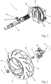
- Fig. 1 shows as an exemplary embodiment of a hand-held implement a blower 1.
- the blower 1 has a backpack 30, which is to be worn by the operator on his back and to which a housing 26 is fixed.
- the blower 1 may also be a hand-held blower 1.
- the present invention may also be advantageous in other hand-held implements, in particular in suction devices, chainsaws, cut-off wheels, brushcutters or the like.
- a drive motor 2 is arranged, which is formed in the embodiment as an internal combustion engine.
- the drive motor 2 shown schematically is advantageously a single-cylinder engine, in particular a two-stroke engine or a mixture-lubricated four-stroke engine.
- the drive motor 2 may also be an electric motor, which is supplied in particular by a battery with energy.
- the blower 1 has a fan coil 33, through which a working air flow is promoted.
- To the fan coil 33 includes a blowpipe 28 at.
- a handle 29 is arranged, with which the operator can guide the blowpipe 28.
- On the handle 29 controls 34 namely a throttle, a throttle lock and a stop switch are arranged. It is also possible to provide further or other operating elements 34.
- an impeller 7 see Fig. 2
- the shaft 3 the crankshaft of the drive motor 2.
- the impeller 7 sucks working air via Heilansauggitter 27, which are provided on the housing 26 and on the back support 30.
- the impeller 7 conveys the working air in the fan coil 33 and from there into the blowpipe 28.
- the impeller 7 may also be an impeller for conveying cooling air, in particular cooling air for the drive motor 2, be.
- Fig. 2 is the wave 3 of the in Fig. 2 not shown drive motor 2 shown.
- An unillustrated piston of the drive motor 2 drives the shaft 3 via a connecting rod 32, wherein the connecting rod 32 is connected via a crank pin 31 with the shaft 3.
- the shaft 3 has a first end 25.
- the impeller 7 is pushed over the first end and fixed by means of a nut 6 on the shaft 3.
- the shaft 3 has an axis of rotation 4 and is driven via the piston in the embodiment in the direction of rotation of the axis 4, starting from the nut 6 to the connecting rod 32 extending counterclockwise in a rotational direction 5.
- the impeller 7 is formed in the embodiment as a radial fan and has blades 16 for conveying the air.
- the impeller 7 has a one-piece body, which is composed of two discs 14 and 15, between which the blades 16 extend.
- the blades 16 of the impeller 7 extend spirally toward the axis of rotation 4.
- the disc 14 has an opening 17.
- the hand-held implement 1 rotates the impeller 7 in the direction of rotation 5 about the rotation axis 4, and the working air is sucked through the opening 17, conveyed by the blades 16 of the impeller 7 to the outside and in the in Fig. 2 not shown blower spiral 33 passed. From there, the working air flows through the blowpipe 28 into the environment.
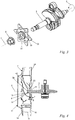
- Fig. 3 shows the same embodiment as Fig. 2 , wherein only one hub 23 of the impeller 7 is shown.
- the hub 23 is connected to the disc 15 of the main body of the impeller 7 connected, in particular embedded therein, encapsulated in the embodiment.
- the hub 23 is held clamped on the shaft 3 by means of the nut 6.
- the hub 23 consists of a sintered material, in particular of a sintered steel material.
- the hub 23 is at least partially, in particular completely, of hardened carbon steel.
- the hub 23 of the impeller 7 is formed star-shaped in the embodiment and has six pointing in the radial direction to the axis of rotation star serrations 35. Each star zigzag 35 includes an opening 36 which is parallel to the axis of rotation 4.
- the impeller 7, the hub 23 and a wheel 24 As in Fig. 4 shown, the impeller 7, the hub 23 and a wheel 24.
- the hub 23 is cast in the wheel 24, inserted in an advantageous embodiment in the wheel 24 and molded.
- the separate formation of the wheel 24 and the hub 23 enables a simplified production of closely toleranced surfaces in the areas of the impeller 7, which come into contact with the shaft 3 and the nut 6.
- the wheel 24 is in the embodiment of a plastic, may advantageously also consist of an aluminum alloy or another material.
- the cast wheel 24 extends through the openings 36 of the hub 35. This creates between the hub 23 and the wheel 24, a positive connection, which is particularly resilient in the circumferential direction to the axis of rotation 4.
- the star shape of the hub 23 results in a circumferentially to the axis of rotation highly resilient positive connection between the hub 23 and wheel 24.
- another convenient, circumferentially positive contour can be selected, having sections of different diameters. The following remarks on the star shape apply equally to such contours.
- the hub 23 is subject to different loads than the wheel 24 and is made in the embodiment of a different material. By producing the impeller 7 from at least two different materials, the mass of the impeller 7 can be reduced. In an advantageous embodiment, the impeller 7 also be made of a material and / or in one piece.
- the hub 23 has two outer, approximately perpendicular to the rotation axis 4 end faces 43, 44, wherein the first end face 43 of the hub 23 facing the nut 6 and the second end face 44 of the hub 23 faces away from the mother.
- the star prongs 35 have a measured in the direction of the rotation axis 4 distance g to the first end face 43 of the hub 23 and measured in the direction of the rotation axis 4 distance h to the second end face 44 of the hub 23.
- the star prongs 35 are formed on the hub 23 so that the distance g is greater than the distance h. Accordingly, the star prongs 35 are closer to the second end face 44 than to the first end face 43.
- the impeller 7 is shown mounted on the shaft 3.
- the hub 23 of the impeller 7 is in contact with the shaft 3.
- the shaft 3 has a thread 10, which extends over a threaded portion 11.
- the nut 6 is screwed onto the threaded portion 11 of the shaft 3 against the hub 23 of the impeller 7.
- the thread 10 of the shaft 3 is formed so that the nut 6 is clamped against the rotational direction 5 of the shaft 3 against the hub 23 of the impeller 7. Since, in the exemplary embodiment, the direction of rotation 5 of the shaft 3 runs in the direction of the axis of rotation 4 from the impeller 7 to the connecting rod 32 in the counterclockwise direction, the thread 10 is designed as a right-hand thread.
- the hub 23 is mounted on the shaft 3 clamped on the nut 6 is attached. Like in the Fig. 6 are shown, on the shaft 3, extending from its first end 25 to the connecting rod 32, the threaded portion 11, a relief groove 21, a cylindrical portion 22, a relief groove 21 and a cone 37 are formed. The centering of the hub 23 is effected by the cone 37 of the shaft 3 and by the cone 38 of the hub 23.
- the cylindrical portion 22 of the shaft 3 has only a slightly smaller diameter than the cylindrical portion 41 of the hub 23 and thus serves to limit the Inclination of a longitudinal axis 42 of the hub
- the threaded portion 11 can be used up to the undercut 21 of the shaft 3 and the thread 10 may be formed such that the hub 23 can also be supported directly on the threaded portion 11.
- the cone 37 of the shaft 3 opens in the direction of the connecting rod 32.
- the hub 23 of the impeller 7 has a cylindrical section 41 with a length e measured in the direction of the longitudinal axis 42 of the hub 23 (FIG. Fig. 11 ). In the exemplary embodiment, the cylindrical section 41 merges into a cone 38 of the hub 23 which opens toward the connecting rod 32.
- the cylindrical section 41 extends in particular over more than half of a length f measured in the direction of the longitudinal axis 42 of the hub 23 (FIG. Fig. 11 ) It may be expedient, instead of or in addition to the cone 38, to provide the hub 23 with a different inner contour in the hub 23, in which the hub 23 increases its distance s, measured radially relative to the axis of rotation 4, with respect to its cylindrical portion 41. Characterized in that the star teeth 35 are closer to the second end face 44 of the hub 23 than at the first end face 43 of the hub 23, the hub 23 is reinforced at its cone 38 and an expansion of the hub 23 when pressed against the cone 37 of the shaft. 3 avoided. Even with other useful, circumferentially positive contours widening of the hub 23 can be avoided if the corresponding contour is closer to the second end face 44 of the hub 23 than at the first end face 43 of the hub 23.
- FIG. 6 shows, in the assembled state, the hub 23 with its cylindrical portion 41 on the cylindrical portion 22 of the shaft 3 in the radial direction of the rotation axis 4 at.
- the cylindrical portions 21 and 41 support the hub 23 on the shaft 3 and thus limit the inclination of the longitudinal axis 42 of the hub 23.
- the hub 23 comes in its cone 38 on the cone 37 of the shaft 3 in a second friction contact surface 13 to the plant, whereby the hub 23 is centered on the shaft 3.
- the screwed onto the threaded portion 11 of the shaft 3 nut 6 contacts the hub 23 of the impeller 7 in a first Reib bitter constitutional 12 and thereby clamps the hub 23 against the cone 37 of the shaft third
- the second friction contact surface 13 forms with the rotation axis 4, a contact surface angle ⁇ , which opens in the direction of the connecting rod 32 out.
- the contact surface angle ⁇ in the exemplary embodiment is at least 15 °, in particular at least 20 °, preferably at least 25 °.
- the contact surface angle ⁇ is in the exemplary embodiment at most 85 °, in particular at most 80 °, preferably at most 75 °. Due to the contact surface angle ⁇ of the second friction contact surface 13, the shaft 3 is tensioned in its cone 37 like a wedge against the cone 28 of the hub 23.
- the contact force between the shaft 3 and the hub 23 is increased in comparison to a contact surface aligned radially with respect to the axis of rotation 4.
- the contact surface angle ⁇ is at least chosen so large that there is no self-locking between the impeller 7 and the shaft 3.
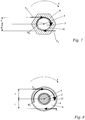
- Fig. 7 is shown in a sectional view, the nut 6 screwed onto the shaft 3.
- the thread pressing force F G acts tangentially to the circumferential direction of the rotation axis 4 and has a distance d to the rotation axis 4.
- the distance d corresponds to the radius of the thread 10.
- the acting thread friction moment M A is formed The product of the thread pressing force and its distance d to the rotation axis 4.
- the thread friction moment M A acting in the threaded portion 11 between the nut 6 and the shaft 3 can be increased by increasing the distance d and / or the thread force F G.
- the acting Gewindereibmoment M A can be transmitted with and against the direction of rotation 5 between the nut 6 and the shaft 3.
- the thread 10 is formed as a fine thread.
- the fine thread is defined according to DIN ISO 261/262.
- the thread 10 is formed as a metric fine thread with a nominal diameter of 12 mm and a pitch of 1.25.
- Fig. 8 is shown in a sectional view, the first friction contact surface 12 of the nut 6 and the hub 23.
- the nut 6 and the hub 23 are clamped against each other, so that between the nut 6 and the hub 23, a contact force.
- This contact force generates a tangential force F T , which corresponds to a frictional force.
- the tangential force F T acts tangentially to the axis of rotation 4 in the first friction contact surface 12 and has a distance r from the axis of rotation 4.
- the first friction moment M 1 forming in the first friction contact surface 12 is the product of the tangential force F T and its distance r from the axis of rotation 4 Accordingly, the first friction moment M 1 acting in the first friction contact surface 12 can be increased by increasing the distance r and / or the tangential force F T.
- the distance r increases if, for example, the distance of the first friction contact surface 12 from the axis of rotation 4 or at least the outer diameter of the friction contact surface 12 is increased.
- the distance r is at least 1.3 times, in an advantageous embodiment at least 1.5 times, in particular at least 1.7 times the distance d.
- the first friction torque M 1 can be transmitted with and against the direction of rotation 5 between the nut 6 and the hub 23.
- the first friction contact surface 12 between the nut 6 and the hub 23 is formed so that the first friction torque M 1 is greater than the Gewindereibmoment M A acting in the threaded portion 11 between the nut 6 and shaft 3.
- the nut 6 is taken from the hub 23.
- Fig. 9 is a sectional view of the shaft 3 is shown, which extends through the second Reibtrust simulation 13 between the hub 23 and the shaft 3.
- the hub 23 and the shaft 6 are clamped against each other, so that between the hub 23 and the shaft 3, a contact force.
- This contact force generates a cone friction force F K.
- the Konusreibkraft F K acts in the second Reibtrust components 13 tangential to the axis of rotation 4 and has a distance s to the axis of rotation 4.
- the second Reibmoment M 2 forming in the second Reib bitterization 13 is the product of the Konusreibkraft F K and its distance s to the axis of rotation.
- the second friction torque M 2 acting in the second friction contact surface 13 can be increased by increasing the distance s and / or the cone friction force F K.
- the second friction torque M 2 can be transmitted with and against the direction of rotation 5 between the hub 23 and the shaft 3.
- the distance s between the Konusreibkraft F K and the axis of rotation 4 is greater than the distance d.
- the friction pairings between the nut 6 and the shaft 3, the hub 23 and the shaft 3 and the hub 23 and the nut 6 have a different distance (d, s, r) measured radially to the axis of rotation 4 to the axis of rotation 4.
- the distance s is smaller than the distance r and the distance s greater than the inner radius d of the nut 6. In an advantageous embodiment, the distance s is at least 1.2 times the distance d. In an advantageous embodiment, the distance s may also be smaller than the inner radius d of the nut 6.
- the nut 6 spans without action by the operator until the sum of the acting Gewindereibmoment M A and the second friction torque M 2 corresponds to the acting on the impeller 7 operating torque and the hub 23 of the impeller 7 so not more slipped on the shaft 3. Slipping the impeller 7 on the shaft 3 by, produces a relative movement between the impeller 7 and the shaft 3.
- the first friction pair is tuned such that the first frictional torque M 1 between the nut 6 and the hub 23 is always larger than the Gewindereibmoment M A acting between the shaft 3 and the nut 6 in the threaded portion 11, no relative movement between the hub 23 and the nut 3 takes place, but the nut 6 is from the impeller 7 rotated relative to the shaft 3. In this case, the nut 6 continues to rotate on the threaded portion 11 and spans axially in the direction of the axis of rotation 4 via the impeller 7 against the cone 37 of the shaft 3.
- the impeller 7 is pressed against the cone 37 of the shaft 3 and tightened, resulting in increases the force acting on the second Reibtrust Structure 13 normal force. If the second friction torque M 2 is sufficiently large that no relative movement takes place between the impeller 7 and the shaft 7 more, the nut 6 is tightened with the final acting Gewindereibmoment M A. To release the nut 3, the final acting Gewindereibmoment M A and the first friction torque M 1 is overcome. The release of the nut 3 is independent of the acting between the impeller 7 and the cone 37 of the shaft 3 second friction moment M 2 . To release the nut 3, no rotation of the impeller 7 is required because the nut 6 can rotate after overcoming the first frictional torque M 1 relative to the impeller 7.
- the operating torque acting on the impeller 7 is transmitted to the shaft 2 to one third via the acting thread friction moment M A and two thirds via the second frictional torque M 2 .
- the first friction torque M 1 is tuned such that it is only slightly larger than the Gewindereibmoment M G. In this way, it is ensured that the relative movement does not take place between the hub 23 and the nut 6, but between the nut 6 and the shaft 3. To release the nut 6 is therefore a moment of slightly more than two-thirds of the operating torque applied.
- the nut 6 has a contact surface 9, which is formed on the end of the nut 6 facing the connecting rod 32.
- the hub 23 of the impeller 7 has a first contact surface 19, which is formed on the connecting rod 32 facing away from the end face of the hub 23, and a second abutment surface 20 which is formed on the cone 38 of the hub 23.
- a contact surface 18 of the shaft 3 is formed.
- the second bearing surface 20 of the impeller 7 forms with the axis of rotation 4 in Fig. 11 shown hub cone angle ⁇ , which is open in the direction of the connecting rod 32.
- the contact surface 18 of the shaft 3 forms with the axis of rotation 4 a shaft cone angle ⁇ , which is also open to the connecting rod 32.
- the cone 37 of the shaft 3 and the cone 38 of the hub 23 are tolerated in such a way that it is advantageous to have a flat contact or at least one line-shaped contact on a largest radius c (FIG. Fig. 12 ) of the cone 37 of the shaft 3 results.
- the shaft cone angle ⁇ is set larger than the hub cone angle ⁇ .
- the shaft cone angle ⁇ is at most one degree, in particular at most half a degree, greater than the hub cone angle ⁇ . If the hub cone angle ⁇ and the cone angle ⁇ are different, the contact surface angle ⁇ between the second friction contact surface 13 and the axis of rotation 4 of the shaft 3 corresponds to the shaft cone angle ⁇ .
- the radius b of the shaft 3 at the first end 39 of the cone 37 is smaller than the radius c of the shaft 3 at the second end 40 of the cone 37.
- the cone 37 has a measured in the direction of the rotation axis 4 length a, which is measured in the direction of the axis of rotation 4 distance between the first End 39 and the second end 40 of the cone 37 of the shaft 3 corresponds.
- the length a is smaller than the radius c at the second end 40 of the cone 37 of the shaft 3, in particular smaller than the radius b of the shaft 3 at the first end 39 of the cone 37.
- the attachment of the impeller 7 shown in the embodiment can be used in hand-held implements that have an impeller 7, such as suction or the like.
- an impeller 7 such as suction or the like.
- such a self-tightening attachment of the impeller 7 is not limited only to impellers 7 for the promotion of working air.
- the impeller 7 can also be an impeller for conveying cooling air, in particular cooling air for the internal combustion engine.
Landscapes
- Engineering & Computer Science (AREA)
- Mechanical Engineering (AREA)
- General Engineering & Computer Science (AREA)
- Architecture (AREA)
- Civil Engineering (AREA)
- Structural Engineering (AREA)
- Chemical & Material Sciences (AREA)
- Combustion & Propulsion (AREA)
- Life Sciences & Earth Sciences (AREA)
- Environmental Sciences (AREA)
- Structures Of Non-Positive Displacement Pumps (AREA)
Abstract
Description
- Die Erfindung betrifft ein handgeführtes Arbeitsgerät der im Oberbegriff des Anspruchs 1 angegebenen Gattung.
- Es sind von Hand zu führende Blasgeräte bekannt, welche ein Gehäuse mit einem darin aufgenommenem Verbrennungsmotor sowie ein am Gehäuse angeordnetes Gebläserad umfassen. Das Gebläserad ist auf einer vom Antriebsmotor angetriebenen Welle angeordnet und mittels einer Mutter gegen eine Wellenschulter geklemmt befestigt auf der Welle gehalten. Nachteilig bei derartigen Blasgeräten ist, dass eine Demontage des Gebläserads nur erschwert möglich ist.
- Der vorliegenden Erfindung liegt die Aufgabe zugrunde, ein handgeführtes Arbeitsgerät der im Oberbegriff des Anspruchs 1 angegebenen Gattung zu schaffen, dessen Gebläseradbefestigung eine einfache Demontage des Gebläserads ermöglicht.
- Diese Aufgabe wird durch ein handgeführtes Arbeitsgerät mit den Merkmalen des Anspruchs 1 gelöst.
- Es ist vorgesehen, dass das Gebläserad im Betrieb des Arbeitsgerätes mittels einer Mutter auf der Welle reibkraftschlüssig durch ein wirkendes finales Anzugsmoment der Mutter gegen Verdrehung gehalten ist. Zwischen der Mutter und der Welle ist über einen Gewindeabschnitt ein um die Drehachse wirkendes Gewindereibmoment übertragbar. Zwischen der Mutter und dem Gebläserad ist über eine erste Reibkontaktfläche ein um die Drehachse wirkendes erstes Reibmoment übertragbar. Die erste Reibkontaktfläche ist so ausgebildet, dass bei einem Mindest-Anzugsmoment der Mutter das übertragbare erste Reibmoment größer als das wirkende Gewindereibmoment ist, wobei das Mindest-Anzugsmoment zwischen 10% und 100% des Betriebsdrehmomentes liegt. Dadurch bewegt im Betrieb des Arbeitsgerätes bei einer Relativbewegung zwischen dem Gebläserad und der Welle das Gebläserad die Mutter über das an der Reibkontaktfläche wirkende erste Reibmoment mit. Dadurch spannt die Mutter das Gebläserad gegen die Welle über die zweite Reibkontaktfläche nach. Die zweite Reibkontaktfläche verläuft konisch zur Drehachse.
- Das Nachspannen der Mutter im Betrieb des Arbeitsgerätes ohne Zutun des Bedieners ermöglicht dem Bediener, die Mutter mit einem nur geringen Anzugsmoment über das Gebläserad gegen die Welle zu verspannen. Die Mutter spannt das Gebläserad bedarfsgerecht bezogen auf die im Betrieb des Arbeitsgerätes auftretenden Belastungen nach. Ein vom Bediener bei der Montage des Gebläserads gewähltes zu hohes Anzugsmoment wird dadurch weitgehend vermieden. Zusätzlich kann der Bediener bei der Montage des Gebläserads von sonst üblichen Sicherheitsfaktoren absehen, welche ein Lösen des Gebläserads vermeiden sollten.
- Das vom Bediener bei der Montage des Gebläserads aufzubringende Mindest-Anzugsmoment ist so groß zu wählen, dass zwischen der Mutter und dem Gebläserad ein Reibkontakt entsteht und in diesem Reibkontakt, der ersten Reibkontaktfläche, das erste Reibmoment übertragen werden kann. Dabei wird bereits bei einem Mindest-Anzugsmoment von mindestens 10%, vorteilhaft von mindestens 20%, insbesondere von mindestens 30% des Betriebsdrehmomentes ein automatisches Nachspannen des Gebläserads erreicht. Das Betriebsdrehmoment ist das im Betrieb des Arbeitsgerätes zwischen der Welle und dem Gebläserad übertragbare Moment. Das automatische Nachziehen des Gebläserads ist dann gegeben, wenn das vom Bediener aufgebrachte Mindest-Anzugsmoment vorteilhaft zwischen 10% bis 90%, insbesondere zwischen 30% bis 80% des Betriebsdrehmomentes liegt. Das Betriebsdrehmoment beträgt vorteilhaft mindestens 80 Nm, insbesondere mindestens 100 Nm. Durch das Nachspannen des Gebläserads durch die Mutter an die Welle wird das Anzugsmoment bedarfsgerecht so groß gewählt, wie es im Betrieb des Arbeitsgeräts zur Befestigung des Gebläserads notwendig ist. Ein zu hohes Anzugsmoment wird dadurch vermieden.
- In der zweiten, konisch verlaufenden Reibkontaktfläche wirkt eine Konusreibkraft in einem Abstand zur Drehachse in Umfangsrichtung der Drehachse. Die Konusreibkraft ist eine Reibkontaktkraft. Die Konusreibkraft in der zweiten Reibkontaktfläche erzeugt aufgrund ihres Abstands zur Drehachse das um die Drehachse wirkende zweite Reibmoment. Durch die Konizität der zweiten Reibkontaktfläche ergibt sich ein Keileffekt. Dieser Keileffekt bewirkt gegenüber einer zur Drehachse senkrecht verlaufenden Reibkontaktfläche eine Erhöhung der Reibkontaktkräfte in der zweiten Reibkontaktfläche zwischen Welle und Gebläserad, so dass sich in der zweiten konisch verlaufenden Reibkontaktfläche hohe Reibmomente übertragen lassen. Dadurch ist bereits bei einem niedrigeren Anzugsmoment das zweite Reibmoment in der zweiten Reibkontaktfläche ausreichend groß, um das Gebläserad auf der Welle reibkraftschlüssig ohne Schlupf zu halten. Die Konizität der zweiten Reibkontaktfläche ermöglicht aufgrund der Übertragbarkeit des hohen zweiten Reibmomentes auch eine Reduzierung des Durchmessers der Welle am Konus. Dadurch kann die Welle klein dimensioniert und Bauraum eingespart werden.
- Die Konizität der zweiten Reibkontaktfläche bewirkt gegenüber einer radial zur Drehachse verlaufenden Kontaktfläche zwischen Gebläserad und Welle eine Vergrößerung der Kontaktfläche. Dadurch reduziert sich die Flächenpressung in der zweiten Reibkontaktfläche, und mögliche Kaltverschweißungen zwischen Welle und Gebläserad werden vermieden. Dadurch wird ein leichtes Demontieren des Gebläserads von der Welle ermöglicht.
- Das zweite Reibmoment in der zweiten Reibkontaktfläche ist vorteilhaft größer als das Gewindereibmoment im Gewindeabschnitt. Das zweite Reibmoment entspricht vorteilhaft mindestens dem 1,3fachen, insbesondere mindestens dem 1,5fachen des Gewindereibmomentes.
- Es ist vorteilhaft vorgesehen, dass eine das erste Reibmoment erzeugende Tangentialkraft an der ersten Reibkontaktfläche in einem Abstand zur Drehachse in Umfangsrichtung der Drehachse wirkt. Der Abstand zur Drehachse entspricht vorteilhaft mindestens dem 1,5fachen Innenradius der Mutter am Gewindeabschnitt. Die Tangentialkraft entspricht der resultierenden Reibkontaktkraft in der ersten Reibkontaktfläche. Die Tangentialkraft erzeugt aufgrund ihres Abstands zur Drehachse das erste Reibmoment, welches um die Drehachse wirkt. Vergrößert sich der Durchmesser der ersten Reibkontaktfläche, erhöht sich der Abstand zwischen der wirkenden Tangentialkraft und der Drehachse. Dabei erhöht sich auch das erste Reibmoment.
- Es ist vorteilhaft vorgesehen, dass die zweite Reibkontaktfläche und die Drehachse einen Winkel von mindestens 15°, vorteilhaft von mindestens 20°, insbesondere von mindestens 25° einschließen. Vorteilhaft schließen die zweite Reibkontaktfläche und die Drehachse einen Winkel von höchstens 80°, vorteilhaft von höchstens 75°, insbesondere von höchstens 70° ein. Vorteilhaft ist die zweite Reibkontaktfläche so ausgebildet und angeordnet, dass in der zweiten Reibkontaktfläche keine Selbsthemmung zwischen dem Gebläserad und der Mutter besteht.
- Mit sich reduzierendem Winkel zwischen der zweiten Reibkontaktfläche und der Drehachse erhöht sich bei gleichbleibendem Anzugsmoment die Kontaktkraft zwischen der Welle und dem Gebläserad und damit auch die Konusreibkraft in der zweiten Reibkontaktfläche. Infolge dessen erhöht sich auch das zweite Reibmoment. Durch den Keileffekt zwischen Gebläserad und Welle und der daraus resultierenden Verstärkung der Konusreibkraft kann das Anzugsmoment reduziert werden und dennoch ein ausreichend großes zweites Reibmoment erzeugt werden, so dass das Gebläserad auf der Welle im Betrieb ohne Schlupf reibschlüssig gehalten ist. Dadurch ist das Lösemoment der Mutter beim Demontieren des Gebläserads von der Welle reduziert.
- Beträgt der Winkel zwischen der zweiten Reibkontaktfläche und der Drehachse vorteilhaft mindestens 15°, so ist die in Richtung der Drehachse gemessene Länge des Konus gegenüber der Länge eines selbsthemmenden Konus vergleichsweise gering. Daher ermöglicht der Winkel zwischen Reibkontaktfläche und der Drehachse eine bauraumsparende Befestigung des Gebläserads auf der Welle in axialer und radialer Richtung der Drehachse.
- Dadurch, dass zwischen Gebläserad und der Welle keine Selbsthemmung besteht, kann das Gebläserad, sofern die Mutter von der Welle gelöst ist, auf einfache Weise von der Welle gezogen werden, insbesondere ohne Hilfe eines Spezialwerkzeuges wie beispielsweise eines Abziehers.
- Es ist vorteilhaft vorgesehen, dass die zweite Reibkontaktfläche aus zwei in Kontakt stehenden Flächen besteht, wobei die Flächen eine Anlagefläche der Welle und eine Anlagefläche, insbesondere eine zweite Anlagefläche des Gebläserads sind. Die Anlageflächen kontaktieren einander vorteilhaft flächig. Es kann aber auch nur eine Linienanlage an einem insbesondere großen Durchmesser des Konus der Welle und der Nabe vorgesehen sein. Vorteilhaft kann eine der zwei in Kontakt stehenden Flächen der zweiten Reibfläche eine Beschichtung und/oder eine Profilierung zur Reibwerterhöhung besitzen. Aus der Reibwerterhöhung resultiert eine Erhöhung der maximal wirkenden Tangentialkraft und damit eine Erhöhung des zweiten Reibmomentes.
- Es ist vorteilhaft vorgesehen, dass in Draufsicht auf eine die Drehachse enthaltende Längsebene der Winkel zwischen der zweiten Anlagefläche des Gebläserads und der Drehachse kleiner ist als der Winkel zwischen der Anlagefläche der Welle und der Drehachse. Vorteilhaft beträgt die Differenz der Winkel weniger als ein Grad, insbesondere weniger als ein halbes Grad. Dadurch wird sichergestellt, dass bei der Montage des Gebläserads auf die Welle die zweite Anlagefläche des Gebläserads und die Anlagefläche der Welle in einem maximalen Abstand zur Drehachse in Kontakt kommen. Dadurch stellt sich auch ein maximaler Abstand zwischen der Tangentialkraft und der Drehachse ein. Der maximale Abstand zwischen der Tangentialkraft und der Drehachse bedingt auch ein möglichst großes übertragbares zweites Reibmoment.
- Vorteilhaft besteht die erste Reibkontaktfläche aus zwei in Kontakt stehenden Flächen, wobei die Flächen eine Anlagefläche der Mutter und eine Anlagefläche, insbesondere eine erste Anlagefläche des Gebläserads sind. Vorzugsweise besitzt mindestens eine der zwei in Kontakt stehenden Flächen der ersten Reibfläche eine Beschichtung und/oder eine Profilierung, zur Reibwerterhöhung. Mittels der Beschichtung oder an der Profilierung kann der Reibwert in der ersten Reibkontaktfläche und damit die Tangentialkraft erhöht werden. Dadurch kann das erste Reibmoment höher als das Gewindereibmoment ausgelegt werden.
- Es ist vorteilhaft vorgesehen, dass das Gewinde als Feingewinde ausgebildet ist. Das Feingewinde ist entsprechend der DIN ISO 261/262 definiert. Das Feingewinde ist vorzugsweise als metrisches Gewinde mit einem Nenndurchmesser 12 und einer Steigung von 1,25 ausgebildet. Aufgrund der geringen Steigung ist der anfängliche Widerstand beim Festdrehen der Mutter gegenüber einem Regelgewinde reduziert. Dadurch ist ein Mitdrehen der Mutter durch das Gebläserad vereinfacht. Zusätzlich kann über das Feingewinde eine höhere Belastung aufgenommen werden, so dass die Welle im Gewindeabschnitt mit einem geringen Durchmesser ausgebildet sein kann.
- Es ist vorteilhaft vorgesehen, dass an der Welle ein zylindrischer Abschnitt ausgebildet ist und das Gebläserad auf dem zylindrischen Abschnitt zur Welle gegen Schrägstellung abgestützt ist. Dadurch wird eine hohe Rundlaufgenauigkeit des Gebläserads ermöglicht und eine Unwucht des Gebläserads vermieden. Da die Herstellbarkeit eines zylindrischen Abschnitts gegenüber einem Gewindeabschnitt mit geringen Toleranzen vergleichsweise einfach und günstig ist, kann durch die Trennung der Funktionen von Abstützung und Klemmung des Gebläserads an der Welle eine genaue und günstige Ausrichtung des Gebläserads auf der Welle erreicht werden.
- Vorteilhaft umfasst das Gebläserad eine Nabe und ein auf der Nabe befestigtes Rad. Die Nabe besteht vorteilhaft aus einem Metall, insbesondere einem Sintermetall, bevorzugt aus einem gesinterten Stahlwerkstoff. Die Nabe besteht insbesondere mindestens teilweise, vorzugsweise vollständig, aus einem gehärteten Kohlenstoffstahl.
- Ausführungsbeispiele der Erfindung werden im Folgenden anhand der Zeichnung erläutert. Es zeigen:
- Fig. 1
- eine schematische Darstellung eines Blasgerätes,
- Fig. 2
- eine perspektivische Explosionsdarstellung des Gebläserads und der Antriebswelle des Blasgerätes nach
Fig. 1 , - Fig. 3
- eine perspektivische Explosionsdarstellung der Nabe des Gebläserads und der Antriebswelle des Blasgerätes nach
Fig. 1 , - Fig. 4
- eine Schnittdarstellung des Gebläserads und der Antriebswelle des Blasgerätes nach
Fig. 1 , - Fig. 5
- eine Seitenansicht der Nabe des Gebläserads und der Antriebswelle des Blasgerätes nach
Fig. 1 , - Fig. 6
- eine Schnittdarstellung der Nabe des Gebläserads und der Antriebswelle des Blasgerätes nach
Fig. 1 , - Fig. 7
- eine Schnittdarstellung der Antriebswelle entlang der Linie VII-VII in
Fig. 6 , - Fig. 8
- eine Schnittdarstellung der Antriebswelle entlang der Linie VIII-VIII in
Fig. 6 , - Fig. 9
- eine Schnittdarstellung der Antriebswelle entlang der Linie IX-IX in
Fig. 6 , - Fig. 10
- eine Explosionsdarstellung der Nabe des Gebläserads und der Antriebswelle des Blasgerätes nach
Fig. 1 in Seitenansicht, - Fig. 11
- eine geschnittene Explosionsdarstellung der Nabe des Gebläserads und der Antriebswelle des Blasgerätes nach
Fig. 1 und - Fig. 12
- eine vergrößerte ausschnittsweise Schnittdarstellung des Gebläserads und der Antriebswelle des Blasgerätes nach
Fig. 1 . -
Fig. 1 zeigt als Ausführungsbeispiel für ein handgeführtes Arbeitsgerät ein Blasgerät 1. Das Blasgerät 1 besitzt eine Rückentrage 30, die vom Bediener auf dem Rücken zu tragen ist und an der ein Gehäuse 26 festgelegt ist. Das Blasgerät 1 kann jedoch auch ein handgetragenes Blasgerät 1 sein. Anstatt bei einem Blasgerät 1 kann die vorliegende Erfindung auch bei anderen handgeführten Arbeitsgeräten, insbesondere bei Sauggeräten, Motorsägen, Trennschleifern, Freischneidern oder dgl. vorteilhaft sein. Im Gehäuse 26 ist ein Antriebsmotor 2 angeordnet, der im Ausführungsbeispiel als Verbrennungsmotor ausgebildet ist. Der schematisch dargestellte Antriebsmotor 2 ist vorteilhaft ein Einzylindermotor, insbesondere ein Zweitaktmotor oder ein gemischgeschmierter Viertaktmotor. Der Antriebsmotor 2 kann jedoch auch ein Elektromotor sein, der insbesondere von einem Akku mit Energie versorgt ist. Das Blasgerät 1 besitzt eine Gebläsespirale 33, durch die ein Arbeitsluftstrom gefördert wird. An die Gebläsespirale 33 schließt ein Blasrohr 28 an. Am Blasrohr 28 ist ein Handgriff 29 angeordnet, mit dem der Bediener das Blasrohr 28 führen kann. Am Handgriff 29 sind Bedienelemente 34, nämlich ein Gashebel, eine Gashebelsperre sowie ein Stoppschalter angeordnet. Es können auch weitere oder andere Bedienelemente 34 vorgesehen sein. Im Gehäuse 26 ist ein Gebläserad 7 (sieheFig. 2 ) angeordnet, welches über eine Welle 3 des Antriebsmotors 2 angetrieben ist. Im Ausführungsbeispiel ist die Welle 3 die Kurbelwelle des Antriebsmotors 2. Das Gebläserad 7 saugt Arbeitsluft über Luftansauggitter 27 an, die am Gehäuse 26 und an der Rückentrage 30 vorgesehen sind. Das Gebläserad 7 fördert die Arbeitsluft in die Gebläsespirale 33 und von dort in das Blasrohr 28. Das Gebläserad 7 kann jedoch auch ein Gebläserad zur Förderung von Kühlluft, insbesondere von Kühlluft für den Antriebsmotor 2, sein. - In
Fig. 2 ist die Welle 3 des inFig. 2 nicht gezeigten Antriebsmotors 2 gezeigt. Ein nicht dargestellter Kolben des Antriebsmotors 2 treibt die Welle 3 über einen Pleuel 32 an, wobei der Pleuel 32 über einen Hubzapfen 31 mit der Welle 3 verbunden ist. Die Welle 3 besitzt ein erstes Ende 25. Das Gebläserad 7 ist über das erste Ende geschoben und mittels einer Mutter 6 auf der Welle 3 befestigt. Die Welle 3 besitzt eine Drehachse 4 und wird über den Kolben im Ausführungsbeispiel in Blickrichtung der Drehachse 4 von der Mutter 6 ausgehend zum Pleuel 32 verlaufend gegen den Uhrzeigersinn in einer Drehrichtung 5 angetrieben. - Das Gebläserad 7 ist im Ausführungsbeispiel als Radialgebläse ausgebildet und besitzt Schaufeln 16 zur Förderung der Luft. Das Gebläserad 7 besitzt einen einteiligen Grundkörper, der aus zwei Scheiben 14 und 15 aufgebaut ist, zwischen denen sich die Schaufeln 16 erstrecken. Die Schaufeln 16 des Gebläserads 7 verlaufen spiralförmig zur Drehachse 4 hin. Die Scheibe 14 besitzt eine Öffnung 17. Im Betrieb des handgeführten Arbeitsgeräts 1 rotiert das Gebläserad 7 in Drehrichtung 5 um die Drehachse 4, und die Arbeitsluft wird über die Öffnung 17 angesaugt, durch die Schaufeln 16 des Gebläserads 7 nach außen gefördert und in die in
Fig. 2 nicht dargestellte Gebläsespirale 33 geleitet. Von dort aus strömt die Arbeitsluft durch das Blasrohr 28 hindurch in die Umgebung. -
Fig. 3 zeigt dasselbe Ausführungsbeispiel wieFig. 2 , wobei nur eine Nabe 23 des Gebläserads 7 dargestellt ist. Die Nabe 23 ist mit der Scheibe 15 des Grundkörpers des Gebläserads 7 verbunden, insbesondere darin eingebettet, im Ausführungsbeispiel umspritzt. Die Nabe 23 ist auf der Welle 3 mittels der Mutter 6 geklemmt gehalten. Solange die Mutter 6 nicht oder nicht ausreichend angezogen ist, kann sich die Nabe 23 des Gebläserads 7 auf der Welle 3 drehen. Im Ausführungsbeispiel besteht die Nabe 23 aus einem Sintermaterial, insbesondere aus einem gesinterten Stahlwerkstoff. Vorzugsweise besteht die Nabe 23 mindestens teilweise, insbesondere vollständig, aus gehärtetem Kohlenstoffstahl. Die Nabe 23 des Gebläserads 7 ist im Ausführungsbeispiel sternförmig ausgebildet und besitzt sechs in radialer Richtung zur Drehachse zeigende Sternzacken 35. Jede einzelne Sternzacke 35 enthält eine Öffnung 36, die parallel zur Drehachse 4 verläuft. - Wie in
Fig. 4 gezeigt, umfasst das Gebläserad 7 die Nabe 23 und ein Rad 24. Die Nabe 23 ist in dem Rad 24 eingegossen, in vorteilhafter Ausführung in das Rad 24 eingelegt und umspritzt. Die separate Ausbildung des Rads 24 und der Nabe 23 ermöglicht eine vereinfachte Herstellung von eng tolerierten Oberflächen in den Bereichen des Gebläserads 7, die mit der Welle 3 und der Mutter 6 in Kontakt treten. Das Rad 24 besteht im Ausführungsbeispiel aus einem Kunststoff, kann vorteilhaft auch aus einer Aluminiumlegierung oder einem anderen Werkstoff bestehen. Das gegossene Rad 24 verläuft durch die Öffnungen 36 der Nabe 35. Dadurch entsteht zwischen der Nabe 23 und dem Rad 24 eine formschlüssige Verbindung, die in Umfangsrichtung zur Drehachse 4 besonders belastbar ist. Die Sternform der Nabe 23 ergibt eine in Umfangsrichtung zur Drehachse hoch belastbare formschlüssige Verbindung zwischen Nabe 23 und Rad 24. Anstelle der Sternform kann auch eine andere zweckmäßige, in Umfangsrichtung formschlüssige Kontur gewählt werden, die Abschnitte unterschiedlichen Durchmessers aufweist. Für solche Konturen gelten gleichermaßen die nachfolgenden Ausführungen zur Sternform. - Die Nabe 23 unterliegt anderen Belastungen als das Rad 24 und ist im Ausführungsbeispiel aus einem anderen Werkstoff hergestellt. Durch die Herstellung des Gebläserads 7 aus mindestens zwei verschiedenen Werkstoffen kann die Masse des Gebläserads 7 reduziert werden. In einem vorteilhaften Ausführungsbeispiel kann das Gebläserad 7 auch aus einem Werkstoff und/oder einteilig hergestellt sein. Die Nabe 23 besitzt zwei äußere, in etwa senkrecht zur Drehachse 4 stehende Stirnseiten 43, 44, wobei die erste Stirnseite 43 der Nabe 23 zur Mutter 6 zugewandt und die zweite Stirnseite 44 der Nabe 23 von der Mutter abgewandt ist. Die Sternzacken 35 besitzen einen in Richtung der Drehachse 4 gemessenen Abstand g zur ersten Stirnseite 43 der Nabe 23 und einen in Richtung der Drehachse 4 gemessenen Abstand h zur zweiten Stirnseite 44 der Nabe 23. Die Sternzacken 35 sind auf der Nabe 23 so ausgebildet, dass der Abstand g größer ist als der Abstand h. Demnach liegen die Sternzacken 35 näher an der zweiten Stirnseite 44 als an der ersten Stirnseite 43.
- In
Fig. 4 ist das Gebläserad 7 auf der Welle 3 montiert gezeigt. Dabei steht die Nabe 23 des Gebläserads 7 mit der Welle 3 in Kontakt. Am gebläseradseitigen ersten Ende 25 der Welle 3 besitzt die Welle 3 ein Gewinde 10, welches sich über einen Gewindeabschnitt 11 erstreckt. Die Mutter 6 ist auf den Gewindeabschnitt 11 der Welle 3 gegen die Nabe 23 des Gebläserads 7 geschraubt. Um ein Loslösen der Mutter 6 im Betrieb des handgeführten Arbeitsgeräts 1 zu vermeiden, ist das Gewinde 10 der Welle 3 so ausgebildet, dass sich die Mutter 6 entgegen der Drehrichtung 5 der Welle 3 gegen die Nabe 23 des Gebläserads 7 festspannt. Da im Ausführungsbeispiel die Drehrichtung 5 der Welle 3 in Richtung der Drehachse 4 vom Gebläserad 7 zum Pleuel 32 hin verlaufend entgegen dem Uhrzeigersinn verläuft, ist das Gewinde 10 als Rechtsgewinde ausgebildet. - Wie in den
Figuren 5 und 6 gezeigt, ist die Nabe 23 auf der Welle 3 über die Mutter 6 geklemmt gehalten befestigt. Wie in derFig. 6 gezeigt, sind an der Welle 3, ausgehend von ihrem ersten Ende 25 zu dem Pleuel 32 hin verlaufend, der Gewindeabschnitt 11, ein Freistich 21, ein zylindrischer Abschnitt 22, ein Freistich 21 und ein Konus 37 ausgebildet. Die Zentrierung der Nabe 23 erfolgt durch den Konus 37 der Welle 3 und durch den Konus 38 der Nabe 23. Der zylindrische Abschnitt 22 der Welle 3 weist einen nur geringfügig kleineren Durchmesser als der zylindrische Abschnitt 41 der Nabe 23 auf und dient damit zur Begrenzung der Schrägstellung einer Längsachse 42 der Nabe 23 bezüglich der Drehachse 4. Zweckmäßig kann der Gewindeabschnitt 11 bis an den Freistich 21 der Welle 3 herangezogen und das Gewinde 10 derart ausgebildet sein, dass sich die Nabe 23 auch direkt auf dem Gewindeabschnitt 11 abstützen kann. Der Konus 37 der Welle 3 öffnet sich in Richtung des Pleuels 32. Die Nabe 23 des Gebläserads 7 besitzt einen zylindrischen Abschnitt 41 mit einer in Richtung der Längsachse 42 der Nabe 23 gemessenen Länge e (Fig. 11 ). Der zylindrische Abschnitt 41 geht im Ausführungsbeispiel in einen zum Pleuel 32 hin öffnenden Konus 38 der Nabe 23 über. Der zylindrische Abschnitt 41 erstreckt sich insbesondere über mehr als die Hälfte einer in Richtung der Längsachse 42 der Nabe 23 gemessenen Länge f (Fig. 11 ) der Nabe 23. Es kann zweckmäßig sein, anstelle oder ergänzend zum Konus 38 der Nabe 23 eine andere Innenkontur in der Nabe 23 vorzusehen, in der die Nabe 23 ihren radial zur Drehachse 4 gemessenen Abstand s gegenüber ihrem zylindrischen Abschnitt 41 vergrößert. Dadurch, dass die Sternzacken 35 näher an der zweiten Stirnseite 44 der Nabe 23 als an der ersten Stirnseite 43 der Nabe 23 liegen, wird die Nabe 23 an ihrem Konus 38 verstärkt und ein Aufweiten der Nabe 23 beim Anpressen an den Konus 37 der Welle 3 vermieden. Auch bei anderen zweckmäßigen, in Umfangsrichtung formschlüssigen Konturen kann ein Aufweiten der Nabe 23 vermieden werden, wenn die entsprechende Kontur näher an der zweiten Stirnseite 44 der Nabe 23 als an der ersten Stirnseite 43 der Nabe 23 liegt. - Wie
Fig. 6 zeigt, liegt in montiertem Zustand die Nabe 23 mit ihrem zylindrischen Abschnitt 41 an dem zylindrischen Abschnitt 22 der Welle 3 in radialer Richtung der Drehachse 4 an. Die zylindrischen Abschnitte 21 und 41 stützen die Nabe 23 auf der Welle 3 ab und begrenzen damit die Schrägstellung der Längsachse 42 der Nabe 23. In axialer Richtung der Drehachse 4 kommt die Nabe 23 in ihrem Konus 38 an dem Konus 37 der Welle 3 in einer zweiten Reibkontaktfläche 13 zur Anlage, wodurch die Nabe 23 auf der Welle 3 zentriert wird. Die auf den Gewindeabschnitt 11 der Welle 3 geschraubte Mutter 6 kontaktiert die Nabe 23 des Gebläserads 7 in einer ersten Reibkontaktfläche 12 und klemmt dadurch die Nabe 23 gegen den Konus 37 der Welle 3. - Wie in
Fig. 6 gezeigt, bildet die zweite Reibkontaktfläche 13 mit der Drehachse 4 einen Kontaktflächenwinkel α, welcher sich in Richtung des Pleuels 32 hin öffnet. Der Kontaktflächenwinkel α beträgt im Ausführungsbeispiel mindestens 15°, insbesondere mindestens 20°, bevorzugt mindestens 25°. Der Kontaktflächenwinkel α beträgt im Ausführungsbeispiel höchstens 85°, insbesondere höchstens 80°, bevorzugt höchstens 75°. Durch den Kontaktflächenwinkel α der zweiten Reibkontaktfläche 13 ist die Welle 3 in ihrem Konus 37 keilartig gegen den Konus 28 der Nabe 23 gespannt. Durch den in der zweiten Reibkontaktfläche 13 auftretenden Keileffekt wird die Kontaktkraft zwischen Welle 3 und Nabe 23 im Vergleich zu einer radial zur Drehachse 4 ausgerichteten Kontaktfläche verstärkt. Je geringer der Kontaktflächenwinkel α ist, wobei der Betrag 0° für den Kontaktflächenwinkel α ausgeschlossen ist, desto größer ist die in der zweiten Reibkontaktfläche 13 wirkende Kontaktkraft. Im Ausführungsbeispiel ist der Kontaktflächenwinkel α mindestens so groß gewählt, dass keine Selbsthemmung zwischen dem Gebläserad 7 und der Welle 3 besteht. - Wie in
Fig. 6 gezeigt, können in montiertem Zustand der Nabe 23 auf der Welle 3 verschiedene Momente übertragen werden. Über das Verspannen der Mutter 6 gegen die Nabe 23 entsteht ein geschlossener Kraftfluss, der vom Gewinde 10 der Welle 3 ausgeht, über die Mutter 6 in die Nabe 23 übergeht, und von der Nabe 23 wieder in die Welle 3 verläuft. Dabei kann im Gewindeabschnitt 11 zwischen Welle 3 und Mutter 6 ein Gewindereibmoment MA übertragen werden. In der ersten Reibkontaktfläche 12 zwischen Mutter 6 und Nabe 23 kann ein erstes Reibmoment M1 übertragen werden. In der zweiten Reibkontaktfläche 13 zwischen Nabe 23 und Welle 3 kann ein zweites Reibmoment M2 übertragen werden. - In
Fig. 7 ist in einer Schnittansicht die Mutter 6 auf die Welle 3 geschraubt gezeigt. In gespanntem Zustand der Nabe 23 des Gebläserads 7 liegt im Gewindeabschnitt 11 eine Gewindereibkraft FG an. Die Gewindereibkraft FG wirkt tangential zur Umfangsrichtung der Drehachse 4 und besitzt einen Abstand d zur Drehachse 4. Der Abstand d entspricht dem Radius des Gewindes 10. Das wirkende Gewindereibmoment MA bildet sich aus dem Produkt der Gewindereibkraft und deren Abstand d zur Drehachse 4. Das in dem Gewindeabschnitt 11 zwischen der Mutter 6 und der Welle 3 wirkende Gewindereibmoment MA kann vergrößert werden, indem der Abstand d und/oder die Gewindereibkraft FG vergrößert werden. Das wirkende Gewindereibmoment MA kann mit und entgegen der Drehrichtung 5 zwischen der Mutter 6 und der Welle 3 übertragen werden. Im Ausführungsbeispiel ist das Gewinde 10 als Feingewinde ausgebildet. In vorteilhaftem Ausführungsbeispiel ist das Feingewinde entsprechend der DIN ISO 261/262 definiert. In vorteilhaftem Ausführungsbeispiel ist das Gewinde 10 als metrisches Feingewinde mit einem Nenndurchmesser von 12 mm und einer Steigung von 1,25 ausgebildet. - In
Fig. 8 ist in einer Schnittansicht die erste Reibkontaktfläche 12 der Mutter 6 und der Nabe 23 gezeigt. In der ersten Reibkontaktfläche 12 sind die Mutter 6 und die Nabe 23 gegeneinander verspannt, so dass zwischen der Mutter 6 und der Nabe 23 eine Kontaktkraft entsteht. Diese Kontaktkraft erzeugt eine Tangentialkraft FT, die einer Reibkraft entspricht. Die Tangentialkraft FT wirkt in der ersten Reibkontaktfläche 12 tangential zur Drehachse 4 und besitzt einen Abstand r zur Drehachse 4. Das sich in der ersten Reibkontaktfläche 12 bildende erste Reibmoment M1 ist das Produkt aus der Tangentialkraft FT und ihrem Abstand r zur Drehachse 4. Demnach kann das in der ersten Reibkontaktfläche 12 wirkende erste Reibmoment M1 vergrößert werden, indem der Abstand r und/oder die Tangentialkraft FT vergrößert werden. Der Abstand r nimmt zu, wenn beispielsweise der Abstand der ersten Reibkontaktfläche 12 zur Drehachse 4 oder zumindest der Außendurchmesser der Reibkontaktfläche 12 vergrößert wird. Der Abstand r beträgt mindestens das 1,3fache, in vorteilhafter Ausführung mindestens das 1,5fache, insbesondere mindestens das 1,7fache des Abstandes d. Das erste Reibmoment M1 kann mit und entgegen der Drehrichtung 5 zwischen der Mutter 6 und der Nabe 23 übertragen werden. - Im Ausführungsbeispiel ist die erste Reibkontaktfläche 12 zwischen der Mutter 6 und der Nabe 23 so ausgebildet, dass das erste Reibmoment M1 größer als das im Gewindeabschnitt 11 zwischen Mutter 6 und Welle 3 wirkende Gewindereibmoment MA ist. Stehen Mutter 6 und Nabe 23 in Kontakt und dreht sich die Nabe 23 relativ zur Welle 3, so wird die Mutter 6 von der Nabe 23 mitgenommen.
- Die Drehung der Nabe 23 relativ zur Welle 3 resultiert daraus, dass die Nabe 23 und die Welle 3 lediglich reibschlüssig verbunden sind und das initial aufgebrachte Anzugsmoment das Trägheitsmoment des Gebläserads 7 nicht oder nicht vollständig kompensiert. Solange die Nabe 23 auf der Welle 3 durchdreht, führt die Nabe 23 eine Relativbewegung entgegen der Drehrichtung der Welle 3 aus.
- In
Fig. 9 ist eine Schnittansicht der Welle 3 gezeigt, welche durch die zweite Reibkontaktfläche 13 zwischen der Nabe 23 und der Welle 3 verläuft. In der zweiten Reibkontaktfläche 13 sind die Nabe 23 und die Welle 6 gegeneinander verspannt, so dass zwischen der Nabe 23 und der Welle 3 eine Kontaktkraft entsteht. Diese Kontaktkraft erzeugt eine Konusreibkraft FK. Die Konusreibkraft FK wirkt in der zweiten Reibkontaktfläche 13 tangential zur Drehachse 4 und besitzt einen Abstand s zur Drehachse 4. Das sich in der zweiten Reibkontaktfläche 13 bildende zweite Reibmoment M2 ist das Produkt aus der Konusreibkraft FK und ihrem Abstand s zur Drehachse 4. Demnach kann das in der zweiten Reibkontaktfläche 13 wirkende zweite Reibmoment M2 vergrößert werden, indem der Abstand s und/oder die Konusreibkraft FK vergrößert werden. Das zweite Reibmoment M2 kann mit und entgegen der Drehrichtung 5 zwischen der Nabe 23 und der Welle 3 übertragen werden. Im Ausführungsbeispiel ist der Abstand s zwischen der Konusreibkraft FK und der Drehachse 4 größer als der Abstand d. Die Reibpaarungen zwischen der Mutter 6 und der Welle 3, der Nabe 23 und der Welle 3 sowie der Nabe 23 und der Mutter 6 weisen einen unterschiedlichen radial zur Drehachse 4 gemessenen Abstand (d, s, r) zur Drehachse 4 auf. In einem vorteilhaften Ausführungsbeispiel ist der Abstand r zwischen der Drehachse 4 und der Tangentialkraft FT größer als der Innenradius d der Mutter 6. Auf diese Weise ist sichergestellt, dass die Mutter 6 solange von der Nabe 23 mitgenommen wird, wie die Nabe 23 auf der Welle 3 durchdreht. In vorteilhafter Ausführung ist der Abstand s kleiner als der Abstand r und der Abstand s größer als der Innenradius d der Mutter 6. In vorteilhafter Ausführung beträgt der Abstand s mindestens dem 1,2fachen Abstand d. In einem vorteilhaften Ausführungsbeispiel kann der Abstand s auch kleiner als der Innenradius d der Mutter 6 sein. - Das Gebläserad 7 wird nach dem nachfolgend beschriebenen Verfahren auf der Welle 3 befestigt:
- Das Gebläserad 7 wird auf die Welle 3 geschoben und über den Konus 37 der Welle 3 zentriert. Anschließend wird die Mutter 6 auf den Gewindeabschnitt 11 der Welle 3 geschraubt, so dass sich die Mutter 6 und das Gebläserad 7 in der ersten Reibkontaktfläche 12 kontaktieren. Die Mutter 6 ist dabei vom Bediener mit einem Mindest-Anzugsmoment, das zwischen 10% und 100% des Betriebsdrehmomentes beträgt, gegen das Gebläserad 7 anzuziehen. Wird die Mutter 6 mit einem Anzugsmoment angezogen, das weniger als das Mindest-Anzugsmoment beträgt, so ist das über die erste Reibkontaktfläche 12 zwischen der Mutter 6 und dem Gebläserad 7 übertragbare erste Reibmoment M1 nicht zwingend größer als das wirkende Gewindereibmoment MA. Um ein Nachziehen der Verbindung im Betrieb zu gewährleisten, muss der Bediener die Mutter 6 mindestens mit dem konstruktiv festgelegten Mindest-Anzugsmoment anziehen. Das Mindest-Anzugsmoment ist dabei so ausgelegt, dass dieses zwischen 10% und 100% des Betriebsdrehmomentes beträgt. Im Ausführungsbeispiel beträgt das Betriebsdrehmoment in etwa 100 Nm. In einem vorteilhaften Ausführungsbeispiel beträgt das Mindest-Anzugsmoment mindestens 30% des Betriebsdrehmomentes. Das Mindest-Anzugsmoment beträgt in vorteilhafter Ausführung höchstens 90%, insbesondere höchstens 80% des Betriebsdrehmomentes. Demnach ist es ausreichend, wenn der Bediener die Mutter 6 nur mit einem geringen Anzugsmoment gegen das Gebläserad 7 verspannt.
- Im Betrieb des handgeführten Arbeitsgeräts 1 spannt sich die Mutter 6 ohne Zutun des Bedieners solange nach, bis die Summe aus dem wirkenden Gewindereibmoment MA und dem zweiten Reibmoment M2 dem auf das Gebläserad 7 wirkenden Betriebsdrehmoment entspricht und die Nabe 23 des Gebläserads 7 damit nicht mehr auf der Welle 3 durchrutscht. Rutscht das Gebläserad 7 auf der Welle 3 durch, entsteht eine Relativbewegung zwischen dem Gebläserad 7 und der Welle 3. Da sich die Mutter 3 und die Nabe 23 bereits in Reibkontakt miteinander befinden und die erste Reibpaarung derart abgestimmt ist, dass das erste Reibmoment M1 zwischen der Mutter 6 und der Nabe 23 stets größer ist als das im Gewindeabschnitt 11 wirkende Gewindereibmoment MA zwischen der Welle 3 und der Mutter 6, findet keine Relativbewegung zwischen der Nabe 23 und der Mutter 3 statt, sondern die Mutter 6 wird von dem Gebläserad 7 relativ zur Welle 3 mitgedreht. Dabei dreht sich die Mutter 6 weiter auf dem Gewindeabschnitt 11 und spannt sich axial in Richtung der Drehachse 4 über das Gebläserad 7 gegen den Konus 37 der Welle 3. Das Gebläserad 7 wird dabei gegen den Konus 37 der Welle 3 gedrückt und nachgespannt, wodurch sich die an der zweiten Reibkontaktfläche 13 wirkende Normalkraft erhöht. Ist das zweite Reibmoment M2 ausreichend groß, dass keine Relativbewegung zwischen Gebläserad 7 und der Welle 7 mehr stattfindet, ist die Mutter 6 mit dem finalen wirkenden Gewindereibmoment MA angezogen. Zum Lösen der Mutter 3 ist das finale wirkende Gewindereibmoment MA sowie das erste Reibmoment M1 zu überwinden. Das Lösen der Mutter 3 erfolgt unabhängig von dem zwischen dem Gebläserad 7 und dem Konus 37 der Welle 3 wirkenden zweiten Reibmoment M2. Zum Lösen der Mutter 3 ist keine Drehung des Gebläserads 7 erforderlich, da sich die Mutter 6 nach Überwindung des ersten Reibmomentes M1 gegenüber dem Gebläserad 7 drehen kann.
- In vorteilhafter Ausführung wird das an dem Gebläserad 7 wirkende Betriebsmoment zu einem Drittel über das wirkende Gewindereibmoment MA und zu zwei Drittel über das zweite Reibmoment M2 auf die Welle 2 übertragen. Dadurch ist beim Lösen der Mutter 6 von der Welle 3 lediglich das wirkende Gewindereibmoment MA in Höhe von einem Drittel des Betriebsmomentes zuzüglich des ersten Reibmomentes M1 zwischen der Mutter 6 und der Nabe 23 zu überwinden. Das erste Reibmoment M1 ist derart abgestimmt, dass es nur geringfügig größer als das Gewindereibmoment MG ist. Auf diese Weise ist sichergestellt, dass die Relativbewegung nicht zwischen der Nabe 23 und der Mutter 6, sondern zwischen der Mutter 6 und der Welle 3 erfolgt. Zum Lösen der Mutter 6 ist demnach ein Moment von etwas mehr als zwei Drittel des Betriebsdrehmomentes aufzubringen.
- In den
Figuren 10 und11 ist gezeigt, dass die Mutter 6 eine Anlagefläche 9 besitzt, welche auf der zum Pleuel 32 zugewandten Stirnseite der Mutter 6 ausgebildet ist. Die Nabe 23 des Gebläserads 7 besitzt eine erste Anlagefläche 19, die an der dem Pleuel 32 abgewandten Stirnseite der Nabe 23 ausgebildet ist, und eine zweite Anlagefläche 20, die an dem Konus 38 der Nabe 23 ausgebildet ist. Am Konus 37 der Welle 3 ist eine Anlagefläche 18 der Welle 3 ausgebildet. In Blickrichtung senkrecht zur Längsebene 8, welche die Drehachse 4 enthält, bildet die zweite Anlagefläche 20 des Gebläserads 7 mit der Drehachse 4 einen inFig. 11 gezeigten Nabenkonuswinkel β, der in Richtung des Pleuels 32 geöffnet ist. In Blickrichtung senkrecht zur Längsebene 8 bildet die Anlagefläche 18 der Welle 3 mit der Drehachse 4 einen Wellenkonuswinkel γ, welcher ebenfalls zum Pleuel 32 hin geöffnet ist. Der Konus 37 der Welle 3 und der Konus 38 der Nabe 23 sind derart toleriert, dass sich vorteilhaft eine flächige Anlage oder zumindest eine linienförmige Anlage auf einem größten Radius c (Fig. 12 ) des Konus 37 der Welle 3 ergibt. Hierfür ist der Wellenkonuswinkel γ größer als der Nabenkonuswinkel β eingestellt. Da der Wellenkonuswinkel γ größer als der Nabenkonuswinkel β ist, kontaktieren sich die zweite Anlagefläche 20 des Gebläserads 7 mit der Anlagefläche 18 der Welle 3 in einem maximalen Abstand zur Drehachse 4 in der zweiten Reibkontaktfläche 13, welcher dem größten Radius c des Konus 37 der Welle 3 entspricht. Demnach wirkt auch die Konusreibkraft FK in einem maximalen Abstand zur Drehachse 4, wodurch ein großes zweites Reibmoment M2 erzeugt wird. - In einem vorteilhaften Ausführungsbeispiel ist der Wellenkonuswinkel γ maximal ein Grad, insbesondere maximal ein halbes Grad, größer als der Nabenkonuswinkel β. Unterscheiden sich der Nabenkonuswinkel β und der Wellenkonuswinkel γ, so entspricht der Kontaktflächenwinkel α zwischen der zweiten Reibkontaktfläche 13 und der Drehachse 4 der Welle 3 dem Wellenkonuswinkel γ.
- Wie
Fig. 12 zeigt, erstreckt sich der Konus 37 der Welle 3 von einem ersten Ende 39 bis zu einem zweiten Ende 40 des Konus 37. Der Radius b der Welle 3 am ersten Ende 39 des Konus 37 ist kleiner als der Radius c der Welle 3 am zweiten Ende 40 des Konus 37. In einem vorteilhaften Ausführungsbeispiel entspricht der Radius b der Welle 3 am ersten Ende 39 mindestens 60%, insbesondere mindestens 65% des Radius c an dem zweiten Ende 40 des Konus 37 der Welle 3. Im Ausführungsbeispiel entspricht der Radius b des ersten Endes 39 maximal 80%, insbesondere maximal 75% des Radius c der Welle 3 am zweiten Ende des Konus 37. Der Konus 37 besitzt eine in Richtung der Drehachse 4 gemessene Länge a, welche dem in Richtung der Drehachse 4 gemessenen Abstand zwischen dem ersten Ende 39 und dem zweiten Ende 40 des Konus 37 der Welle 3 entspricht. In einem vorteilhaften Ausführungsbeispiel ist die Länge a kleiner als der Radius c am zweiten Ende 40 des Konus 37 der Welle 3, insbesondere kleiner als der Radius b der Welle 3 am ersten Ende 39 des Konus 37. - Die im Ausführungsbeispiel gezeigte Befestigung des Gebläserads 7 kann bei handgeführten Arbeitsgeräten eingesetzt werden, die ein Gebläserad 7 besitzen, wie beispielsweise Sauggeräte oder dgl. Dabei ist eine derartige sich selbst nachziehende Befestigung des Gebläserads 7 nicht nur auf Gebläseräder 7 zur Förderung von Arbeitsluft beschränkt. Das Gebläserad 7 kann insbesondere auch ein Gebläserad zur Förderung von Kühlluft, insbesondere von Kühlluft für den Verbrennungsmotor, sein.
Claims (12)
- Handgeführtes Arbeitsgerät mit einem Antriebsmotor (2), mit einer vom Antriebsmotor (2) um eine Drehachse (4) rotierend angetriebenen Welle (3) und mit einem Gebläserad (7), wobei das Gebläserad (7) mittels einer Mutter (6) auf der Welle (3) reibkraftschlüssig gegen Verdrehung gehalten ist, wobei die Mutter (6) und die Welle (3) über einen Gewindeabschnitt (11) im Kontakt stehen, und zwischen der Mutter (6) und der Welle (3) über den Gewindeabschnitt (11) ein um die Drehachse (4) wirkendes Gewindereibmoment (MA) übertragbar ist, wobei die Mutter (6) und das Gebläserad (7) über eine erste Reibkontaktfläche (12) in Kontakt stehen, und zwischen der Mutter (6) und dem Gebläserad (7) über die erste Reibkontaktfläche ein um die Drehachse (4) wirkendes erstes Reibmoment (M1) übertragbar ist, und wobei das Gebläserad (7) und die Welle (3) über eine zweite Reibkontaktfläche (13) in Kontakt stehen,
dadurch gekennzeichnet, dass die erste Reibkontaktfläche (12) so ausgebildet ist, dass bei einem Mindest-Anzugsmoment der Mutter (6), das zwischen 10% und 100% des Betriebsdrehmomentes liegt, das über die erste Reibkontaktfläche (12) zwischen der Mutter (6) und dem Gebläserad (7) übertragbare erste Reibmoment (M1) größer ist als das wirkende Gewindereibmoment (MA), so dass im Betrieb des Arbeitsgerätes (1) bei einer Relativbewegung zwischen dem Gebläserad (7) und der Welle (3) das Gebläserad (7) die Mutter (6) über das an der ersten Reibkontaktfläche (12) wirkende erste Reibmoment (M1) mitbewegt, so dass die Mutter (6) das Gebläserad (7) gegen die Welle (3) über die zweite Reibkontaktfläche (13) nachspannt, und dass die zweite Reibkontaktfläche (13) zur Drehachse (4) konisch verläuft. - Arbeitsgerät nach Anspruch 1,
dadurch gekennzeichnet, dass eine das erste Reibmoment (M1) bildende Tangentialkraft (FT) an der ersten Reibkontaktfläche (12) in einem Abstand (s) zur Drehachse (4) in Umfangsrichtung der Drehachse (4) wirkt, wobei der Abstand (s) mindestens dem 1,5fachen Innenradius (d) der Mutter (6) am Gewindeabschnitt (11) entspricht. - Arbeitsgerät nach Anspruch 1 oder 2,
dadurch gekennzeichnet, dass die zweite Reibkontaktfläche (13) und die Drehachse (4) einen Winkel (α) von mindestens 15° einschließen. - Arbeitsgerät nach einem der Ansprüche 1 bis 3,
dadurch gekennzeichnet, dass die zweite Reibkontaktfläche (13) und die Drehachse (4) einen Winkel (α) von höchstens 75° einschließen. - Arbeitsgerät nach einem der Ansprüche 1 bis 4,
dadurch gekennzeichnet, dass die zweite Reibkontaktfläche (13) so ausgebildet und angeordnet ist, dass in der zweiten Reibkontaktfläche (13) keine Selbsthemmung zwischen dem Gebläserad (7) und der Mutter (6) besteht. - Arbeitsgerät nach einem der Ansprüche 1 bis 5,
dadurch gekennzeichnet, dass die zweite Reibkontaktfläche (13) aus zwei im Kontakt stehenden Flächen besteht, wobei die Flächen eine Anlagefläche (18) der Welle (3) und eine zweite Anlagefläche (20) des Gebläserads (7) sind. - Arbeitsgerät nach Anspruch 6,
dadurch gekennzeichnet, dass in Draufsicht auf eine die Drehachse (4) enthaltende Längsebene (8) der Winkel (β) zwischen der zweiten Anlagefläche (20) des Gebläserads (7) und der Drehachse (4) kleiner ist als der Winkel (γ) zwischen der Anlagefläche (18) der Welle (3) und der Drehachse (4). - Arbeitsgerät nach einem der Ansprüche 1 bis 7,
dadurch gekennzeichnet, dass die erste Reibkontaktfläche (12) aus zwei im Kontakt stehenden Flächen besteht, wobei die Flächen eine Anlagefläche (9) der Mutter (6) und eine erste Anlagefläche (19) des Gebläserads (7) sind. - Arbeitsgerät nach einem der Ansprüche 1 bis 8,
dadurch gekennzeichnet, dass das Gewinde (10) als Feingewinde ausgebildet ist. - Arbeitsgerät nach einem der Ansprüche 1 bis 9,
dadurch gekennzeichnet, dass an der Welle (3) ein zylindrischer Abschnitt (22) ausgebildet ist und das Gebläserad (7) auf dem zylindrischen Abschnitt (22) zur Welle (3) gegen Schrägstellung abgestützt ist. - Arbeitsgerät nach einem der Ansprüche 1 bis 10,
dadurch gekennzeichnet, dass das Gebläserad (7) eine Nabe (23) und ein auf der Nabe (23) befestigtes Rad (24) umfasst, - Arbeitsgerät nach Anspruch 11,
dadurch gekennzeichnet, dass die Nabe (23) aus einem Metall, insbesondere einem Sintermetall besteht.
Priority Applications (3)
| Application Number | Priority Date | Filing Date | Title |
|---|---|---|---|
| EP17001545.7A EP3456480B1 (de) | 2017-09-15 | 2017-09-15 | Handgeführtes arbeitsgerät |
| US16/131,930 US10941786B2 (en) | 2017-09-15 | 2018-09-14 | Handheld work apparatus |
| CN201811082306.0A CN109505785B (zh) | 2017-09-15 | 2018-09-17 | 手引导式工作器械 |
Applications Claiming Priority (1)
| Application Number | Priority Date | Filing Date | Title |
|---|---|---|---|
| EP17001545.7A EP3456480B1 (de) | 2017-09-15 | 2017-09-15 | Handgeführtes arbeitsgerät |
Publications (2)
| Publication Number | Publication Date |
|---|---|
| EP3456480A1 true EP3456480A1 (de) | 2019-03-20 |
| EP3456480B1 EP3456480B1 (de) | 2021-11-03 |
Family
ID=59901318
Family Applications (1)
| Application Number | Title | Priority Date | Filing Date |
|---|---|---|---|
| EP17001545.7A Active EP3456480B1 (de) | 2017-09-15 | 2017-09-15 | Handgeführtes arbeitsgerät |
Country Status (3)
| Country | Link |
|---|---|
| US (1) | US10941786B2 (de) |
| EP (1) | EP3456480B1 (de) |
| CN (1) | CN109505785B (de) |
Families Citing this family (2)
| Publication number | Priority date | Publication date | Assignee | Title |
|---|---|---|---|---|
| US11788741B2 (en) * | 2020-04-01 | 2023-10-17 | Maxton Engineering Ltd. | Window fan and method for quickly assembling and disassembling the same |
| CN114251342B (zh) * | 2021-12-30 | 2024-03-22 | 上海洛轲智能科技有限公司 | 自锁螺母设计方法、自锁螺母、自锁组件 |
Citations (4)
| Publication number | Priority date | Publication date | Assignee | Title |
|---|---|---|---|---|
| DE3347289A1 (de) * | 1983-01-08 | 1984-07-12 | Robert Bosch Gmbh, 7000 Stuttgart | Generator fuer fahrzeuge mit durch eine bundmutter befestigter riemenscheibe |
| US20080022552A1 (en) * | 2006-07-28 | 2008-01-31 | Mabe Canada Inc. | Blower wheel attachment for clothes dryer |
| WO2012069770A1 (fr) * | 2010-11-26 | 2012-05-31 | Fläkt Solyvent-Ventec | Fixation de roue de ventilateur par bagues coniques accommodant la dilatation |
| EP2589704A2 (de) * | 2011-11-02 | 2013-05-08 | Yamabiko Corporation | Arbeitsmaschine mit Blasluft |
Family Cites Families (3)
| Publication number | Priority date | Publication date | Assignee | Title |
|---|---|---|---|---|
| US4295753A (en) * | 1977-11-10 | 1981-10-20 | Mcculloch Corporation | Torque transmitting apparatus |
| DE4142013A1 (de) * | 1991-12-19 | 1993-06-24 | Behr Gmbh & Co | Fluessigkeitsreibungskupplung |
| JP2006307690A (ja) * | 2005-04-27 | 2006-11-09 | Kioritz Corp | 動力ユニット |
-
2017
- 2017-09-15 EP EP17001545.7A patent/EP3456480B1/de active Active
-
2018
- 2018-09-14 US US16/131,930 patent/US10941786B2/en active Active
- 2018-09-17 CN CN201811082306.0A patent/CN109505785B/zh active Active
Patent Citations (4)
| Publication number | Priority date | Publication date | Assignee | Title |
|---|---|---|---|---|
| DE3347289A1 (de) * | 1983-01-08 | 1984-07-12 | Robert Bosch Gmbh, 7000 Stuttgart | Generator fuer fahrzeuge mit durch eine bundmutter befestigter riemenscheibe |
| US20080022552A1 (en) * | 2006-07-28 | 2008-01-31 | Mabe Canada Inc. | Blower wheel attachment for clothes dryer |
| WO2012069770A1 (fr) * | 2010-11-26 | 2012-05-31 | Fläkt Solyvent-Ventec | Fixation de roue de ventilateur par bagues coniques accommodant la dilatation |
| EP2589704A2 (de) * | 2011-11-02 | 2013-05-08 | Yamabiko Corporation | Arbeitsmaschine mit Blasluft |
Also Published As
| Publication number | Publication date |
|---|---|
| EP3456480B1 (de) | 2021-11-03 |
| CN109505785B (zh) | 2022-03-15 |
| US10941786B2 (en) | 2021-03-09 |
| US20190085861A1 (en) | 2019-03-21 |
| CN109505785A (zh) | 2019-03-22 |
Similar Documents
| Publication | Publication Date | Title |
|---|---|---|
| EP2418055B1 (de) | Handgeführtes Arbeitsgerät | |
| EP1647366B1 (de) | Werkzeugmaschine mit einem Überlastschutz | |
| DE29501158U1 (de) | Arretiervorrichtung für eine Antriebswelle | |
| DE10033205B4 (de) | Reibungskupplung mit Kühlventilator zur Druckplattenkühlung | |
| DE20313211U1 (de) | Haltevorrichtung | |
| EP3456480B1 (de) | Handgeführtes arbeitsgerät | |
| DE102006047006A1 (de) | Kraftübertragungseinrichtung | |
| DE102010033072B4 (de) | Trockener Freilauf zwischen Anlasser und Kupplung | |
| DE10311917B4 (de) | Kupplung zur reibschlüssigen Drehverbindung von Maschinenteilen | |
| EP1137558B1 (de) | Vorrichtung zum befestigen eines wischarms auf einer antriebswelle | |
| DE102010039889A1 (de) | Vorrichtung zur Anordnung eines Verdichterrads an einer Antriebswelle einer Strömungsmaschine | |
| DE10249914B4 (de) | Handwerkzeug | |
| DE102009025330A1 (de) | Kühlmittelpumpe | |
| DE102015203895B4 (de) | Nockenwellenbaugruppe mit einem Nockenwellenversteller und einer Nockenwelle | |
| DE102005047602A1 (de) | Handwerkzeugmaschine | |
| WO2020233734A1 (de) | Riemenscheibenentkoppler mit beidseitiger axialverzahnung sowie nebenaggregattrieb | |
| DE102011080889B4 (de) | Elektrische Maschine sowie Verfahren zur Montage einer elektrischen Maschine | |
| EP2025959B1 (de) | Maschinenelement für eine Welle-Nabe-Verbindung und Herstellungsverfahren für eine Welle-Nabe-Verbindung | |
| CH449931A (de) | Spannvorrichtung für das Blatt einer Handkreissäge | |
| EP2557334A1 (de) | Schaltbare Riemenscheibe | |
| DE10021339A1 (de) | Getriebekopf | |
| EP1533091A1 (de) | Spannvorrichtung für ein Werkzeugmaschinen-Bearbeitungselement | |
| CH616727A5 (en) | Locking device for the rotating shaft of a machine, especially a turbocharger | |
| DE102024105357B3 (de) | Handgeführtes, motorbetriebenes Arbeitsgerät, insbesondere Benzinmotorsäge | |
| EP3748193A2 (de) | Spannanordnung mit spannrolle und vorrichtung zum einstellen einer spannanordnung |
Legal Events
| Date | Code | Title | Description |
|---|---|---|---|
| PUAI | Public reference made under article 153(3) epc to a published international application that has entered the european phase |
Free format text: ORIGINAL CODE: 0009012 |
|
| STAA | Information on the status of an ep patent application or granted ep patent |
Free format text: STATUS: THE APPLICATION HAS BEEN PUBLISHED |
|
| AK | Designated contracting states |
Kind code of ref document: A1 Designated state(s): AL AT BE BG CH CY CZ DE DK EE ES FI FR GB GR HR HU IE IS IT LI LT LU LV MC MK MT NL NO PL PT RO RS SE SI SK SM TR |
|
| AX | Request for extension of the european patent |
Extension state: BA ME |
|
| STAA | Information on the status of an ep patent application or granted ep patent |
Free format text: STATUS: REQUEST FOR EXAMINATION WAS MADE |
|
| 17P | Request for examination filed |
Effective date: 20190917 |
|
| RBV | Designated contracting states (corrected) |
Designated state(s): AL AT BE BG CH CY CZ DE DK EE ES FI FR GB GR HR HU IE IS IT LI LT LU LV MC MK MT NL NO PL PT RO RS SE SI SK SM TR |
|
| GRAP | Despatch of communication of intention to grant a patent |
Free format text: ORIGINAL CODE: EPIDOSNIGR1 |
|
| STAA | Information on the status of an ep patent application or granted ep patent |
Free format text: STATUS: GRANT OF PATENT IS INTENDED |
|
| INTG | Intention to grant announced |
Effective date: 20201218 |
|
| GRAJ | Information related to disapproval of communication of intention to grant by the applicant or resumption of examination proceedings by the epo deleted |
Free format text: ORIGINAL CODE: EPIDOSDIGR1 |
|
| STAA | Information on the status of an ep patent application or granted ep patent |
Free format text: STATUS: REQUEST FOR EXAMINATION WAS MADE |
|
| INTC | Intention to grant announced (deleted) | ||
| GRAP | Despatch of communication of intention to grant a patent |
Free format text: ORIGINAL CODE: EPIDOSNIGR1 |
|
| STAA | Information on the status of an ep patent application or granted ep patent |
Free format text: STATUS: GRANT OF PATENT IS INTENDED |
|
| INTG | Intention to grant announced |
Effective date: 20210428 |
|
| GRAS | Grant fee paid |
Free format text: ORIGINAL CODE: EPIDOSNIGR3 |
|
| GRAA | (expected) grant |
Free format text: ORIGINAL CODE: 0009210 |
|
| STAA | Information on the status of an ep patent application or granted ep patent |
Free format text: STATUS: THE PATENT HAS BEEN GRANTED |
|
| AK | Designated contracting states |
Kind code of ref document: B1 Designated state(s): AL AT BE BG CH CY CZ DE DK EE ES FI FR GB GR HR HU IE IS IT LI LT LU LV MC MK MT NL NO PL PT RO RS SE SI SK SM TR |
|
| REG | Reference to a national code |
Ref country code: GB Ref legal event code: FG4D Free format text: NOT ENGLISH |
|
| REG | Reference to a national code |
Ref country code: AT Ref legal event code: REF Ref document number: 1443551 Country of ref document: AT Kind code of ref document: T Effective date: 20211115 Ref country code: CH Ref legal event code: EP |
|
| REG | Reference to a national code |
Ref country code: IE Ref legal event code: FG4D Free format text: LANGUAGE OF EP DOCUMENT: GERMAN |
|
| REG | Reference to a national code |
Ref country code: DE Ref legal event code: R096 Ref document number: 502017011865 Country of ref document: DE |
|
| REG | Reference to a national code |
Ref country code: LT Ref legal event code: MG9D |
|
| REG | Reference to a national code |
Ref country code: NL Ref legal event code: MP Effective date: 20211103 |
|
| PG25 | Lapsed in a contracting state [announced via postgrant information from national office to epo] |
Ref country code: RS Free format text: LAPSE BECAUSE OF FAILURE TO SUBMIT A TRANSLATION OF THE DESCRIPTION OR TO PAY THE FEE WITHIN THE PRESCRIBED TIME-LIMIT Effective date: 20211103 Ref country code: LT Free format text: LAPSE BECAUSE OF FAILURE TO SUBMIT A TRANSLATION OF THE DESCRIPTION OR TO PAY THE FEE WITHIN THE PRESCRIBED TIME-LIMIT Effective date: 20211103 Ref country code: FI Free format text: LAPSE BECAUSE OF FAILURE TO SUBMIT A TRANSLATION OF THE DESCRIPTION OR TO PAY THE FEE WITHIN THE PRESCRIBED TIME-LIMIT Effective date: 20211103 Ref country code: BG Free format text: LAPSE BECAUSE OF FAILURE TO SUBMIT A TRANSLATION OF THE DESCRIPTION OR TO PAY THE FEE WITHIN THE PRESCRIBED TIME-LIMIT Effective date: 20220203 |
|
| PG25 | Lapsed in a contracting state [announced via postgrant information from national office to epo] |
Ref country code: IS Free format text: LAPSE BECAUSE OF FAILURE TO SUBMIT A TRANSLATION OF THE DESCRIPTION OR TO PAY THE FEE WITHIN THE PRESCRIBED TIME-LIMIT Effective date: 20220303 Ref country code: SE Free format text: LAPSE BECAUSE OF FAILURE TO SUBMIT A TRANSLATION OF THE DESCRIPTION OR TO PAY THE FEE WITHIN THE PRESCRIBED TIME-LIMIT Effective date: 20211103 Ref country code: PT Free format text: LAPSE BECAUSE OF FAILURE TO SUBMIT A TRANSLATION OF THE DESCRIPTION OR TO PAY THE FEE WITHIN THE PRESCRIBED TIME-LIMIT Effective date: 20220303 Ref country code: PL Free format text: LAPSE BECAUSE OF FAILURE TO SUBMIT A TRANSLATION OF THE DESCRIPTION OR TO PAY THE FEE WITHIN THE PRESCRIBED TIME-LIMIT Effective date: 20211103 Ref country code: NO Free format text: LAPSE BECAUSE OF FAILURE TO SUBMIT A TRANSLATION OF THE DESCRIPTION OR TO PAY THE FEE WITHIN THE PRESCRIBED TIME-LIMIT Effective date: 20220203 Ref country code: NL Free format text: LAPSE BECAUSE OF FAILURE TO SUBMIT A TRANSLATION OF THE DESCRIPTION OR TO PAY THE FEE WITHIN THE PRESCRIBED TIME-LIMIT Effective date: 20211103 Ref country code: LV Free format text: LAPSE BECAUSE OF FAILURE TO SUBMIT A TRANSLATION OF THE DESCRIPTION OR TO PAY THE FEE WITHIN THE PRESCRIBED TIME-LIMIT Effective date: 20211103 Ref country code: HR Free format text: LAPSE BECAUSE OF FAILURE TO SUBMIT A TRANSLATION OF THE DESCRIPTION OR TO PAY THE FEE WITHIN THE PRESCRIBED TIME-LIMIT Effective date: 20211103 Ref country code: GR Free format text: LAPSE BECAUSE OF FAILURE TO SUBMIT A TRANSLATION OF THE DESCRIPTION OR TO PAY THE FEE WITHIN THE PRESCRIBED TIME-LIMIT Effective date: 20220204 Ref country code: ES Free format text: LAPSE BECAUSE OF FAILURE TO SUBMIT A TRANSLATION OF THE DESCRIPTION OR TO PAY THE FEE WITHIN THE PRESCRIBED TIME-LIMIT Effective date: 20211103 |
|
| PG25 | Lapsed in a contracting state [announced via postgrant information from national office to epo] |
Ref country code: SM Free format text: LAPSE BECAUSE OF FAILURE TO SUBMIT A TRANSLATION OF THE DESCRIPTION OR TO PAY THE FEE WITHIN THE PRESCRIBED TIME-LIMIT Effective date: 20211103 Ref country code: SK Free format text: LAPSE BECAUSE OF FAILURE TO SUBMIT A TRANSLATION OF THE DESCRIPTION OR TO PAY THE FEE WITHIN THE PRESCRIBED TIME-LIMIT Effective date: 20211103 Ref country code: RO Free format text: LAPSE BECAUSE OF FAILURE TO SUBMIT A TRANSLATION OF THE DESCRIPTION OR TO PAY THE FEE WITHIN THE PRESCRIBED TIME-LIMIT Effective date: 20211103 Ref country code: EE Free format text: LAPSE BECAUSE OF FAILURE TO SUBMIT A TRANSLATION OF THE DESCRIPTION OR TO PAY THE FEE WITHIN THE PRESCRIBED TIME-LIMIT Effective date: 20211103 Ref country code: DK Free format text: LAPSE BECAUSE OF FAILURE TO SUBMIT A TRANSLATION OF THE DESCRIPTION OR TO PAY THE FEE WITHIN THE PRESCRIBED TIME-LIMIT Effective date: 20211103 Ref country code: CZ Free format text: LAPSE BECAUSE OF FAILURE TO SUBMIT A TRANSLATION OF THE DESCRIPTION OR TO PAY THE FEE WITHIN THE PRESCRIBED TIME-LIMIT Effective date: 20211103 |
|
| REG | Reference to a national code |
Ref country code: DE Ref legal event code: R097 Ref document number: 502017011865 Country of ref document: DE |
|
| PLBE | No opposition filed within time limit |
Free format text: ORIGINAL CODE: 0009261 |
|
| STAA | Information on the status of an ep patent application or granted ep patent |
Free format text: STATUS: NO OPPOSITION FILED WITHIN TIME LIMIT |
|
| 26N | No opposition filed |
Effective date: 20220804 |
|
| PG25 | Lapsed in a contracting state [announced via postgrant information from national office to epo] |
Ref country code: AL Free format text: LAPSE BECAUSE OF FAILURE TO SUBMIT A TRANSLATION OF THE DESCRIPTION OR TO PAY THE FEE WITHIN THE PRESCRIBED TIME-LIMIT Effective date: 20211103 |
|
| PG25 | Lapsed in a contracting state [announced via postgrant information from national office to epo] |
Ref country code: SI Free format text: LAPSE BECAUSE OF FAILURE TO SUBMIT A TRANSLATION OF THE DESCRIPTION OR TO PAY THE FEE WITHIN THE PRESCRIBED TIME-LIMIT Effective date: 20211103 |
|
| PG25 | Lapsed in a contracting state [announced via postgrant information from national office to epo] |
Ref country code: MC Free format text: LAPSE BECAUSE OF FAILURE TO SUBMIT A TRANSLATION OF THE DESCRIPTION OR TO PAY THE FEE WITHIN THE PRESCRIBED TIME-LIMIT Effective date: 20211103 |
|
| REG | Reference to a national code |
Ref country code: CH Ref legal event code: PL |
|
| GBPC | Gb: european patent ceased through non-payment of renewal fee |
Effective date: 20220915 |
|
| REG | Reference to a national code |
Ref country code: BE Ref legal event code: MM Effective date: 20220930 |
|
| PG25 | Lapsed in a contracting state [announced via postgrant information from national office to epo] |
Ref country code: IT Free format text: LAPSE BECAUSE OF FAILURE TO SUBMIT A TRANSLATION OF THE DESCRIPTION OR TO PAY THE FEE WITHIN THE PRESCRIBED TIME-LIMIT Effective date: 20211103 |
|
| PG25 | Lapsed in a contracting state [announced via postgrant information from national office to epo] |
Ref country code: LU Free format text: LAPSE BECAUSE OF NON-PAYMENT OF DUE FEES Effective date: 20220915 |
|
| PG25 | Lapsed in a contracting state [announced via postgrant information from national office to epo] |
Ref country code: LI Free format text: LAPSE BECAUSE OF NON-PAYMENT OF DUE FEES Effective date: 20220930 Ref country code: IE Free format text: LAPSE BECAUSE OF NON-PAYMENT OF DUE FEES Effective date: 20220915 Ref country code: CH Free format text: LAPSE BECAUSE OF NON-PAYMENT OF DUE FEES Effective date: 20220930 |
|
| PG25 | Lapsed in a contracting state [announced via postgrant information from national office to epo] |
Ref country code: BE Free format text: LAPSE BECAUSE OF NON-PAYMENT OF DUE FEES Effective date: 20220930 |
|
| PG25 | Lapsed in a contracting state [announced via postgrant information from national office to epo] |
Ref country code: GB Free format text: LAPSE BECAUSE OF NON-PAYMENT OF DUE FEES Effective date: 20220915 |
|
| REG | Reference to a national code |
Ref country code: AT Ref legal event code: MM01 Ref document number: 1443551 Country of ref document: AT Kind code of ref document: T Effective date: 20220915 |
|
| PG25 | Lapsed in a contracting state [announced via postgrant information from national office to epo] |
Ref country code: AT Free format text: LAPSE BECAUSE OF NON-PAYMENT OF DUE FEES Effective date: 20220915 |
|
| PG25 | Lapsed in a contracting state [announced via postgrant information from national office to epo] |
Ref country code: HU Free format text: LAPSE BECAUSE OF FAILURE TO SUBMIT A TRANSLATION OF THE DESCRIPTION OR TO PAY THE FEE WITHIN THE PRESCRIBED TIME-LIMIT; INVALID AB INITIO Effective date: 20170915 |
|
| PG25 | Lapsed in a contracting state [announced via postgrant information from national office to epo] |
Ref country code: CY Free format text: LAPSE BECAUSE OF FAILURE TO SUBMIT A TRANSLATION OF THE DESCRIPTION OR TO PAY THE FEE WITHIN THE PRESCRIBED TIME-LIMIT Effective date: 20211103 |
|
| PG25 | Lapsed in a contracting state [announced via postgrant information from national office to epo] |
Ref country code: MK Free format text: LAPSE BECAUSE OF FAILURE TO SUBMIT A TRANSLATION OF THE DESCRIPTION OR TO PAY THE FEE WITHIN THE PRESCRIBED TIME-LIMIT Effective date: 20211103 |
|
| PG25 | Lapsed in a contracting state [announced via postgrant information from national office to epo] |
Ref country code: TR Free format text: LAPSE BECAUSE OF FAILURE TO SUBMIT A TRANSLATION OF THE DESCRIPTION OR TO PAY THE FEE WITHIN THE PRESCRIBED TIME-LIMIT Effective date: 20211103 |
|
| PG25 | Lapsed in a contracting state [announced via postgrant information from national office to epo] |
Ref country code: MT Free format text: LAPSE BECAUSE OF FAILURE TO SUBMIT A TRANSLATION OF THE DESCRIPTION OR TO PAY THE FEE WITHIN THE PRESCRIBED TIME-LIMIT Effective date: 20211103 |
|
| PGFP | Annual fee paid to national office [announced via postgrant information from national office to epo] |
Ref country code: DE Payment date: 20250926 Year of fee payment: 9 |
|
| PGFP | Annual fee paid to national office [announced via postgrant information from national office to epo] |
Ref country code: FR Payment date: 20250925 Year of fee payment: 9 |