EP3456470A2 - System for changing and inserting or placing tools on a machine tool and machine tool equipped with such a system - Google Patents
System for changing and inserting or placing tools on a machine tool and machine tool equipped with such a system Download PDFInfo
- Publication number
- EP3456470A2 EP3456470A2 EP18194739.1A EP18194739A EP3456470A2 EP 3456470 A2 EP3456470 A2 EP 3456470A2 EP 18194739 A EP18194739 A EP 18194739A EP 3456470 A2 EP3456470 A2 EP 3456470A2
- Authority
- EP
- European Patent Office
- Prior art keywords
- tool
- diameter
- radius
- loaded
- measuring device
- Prior art date
- Legal status (The legal status is an assumption and is not a legal conclusion. Google has not performed a legal analysis and makes no representation as to the accuracy of the status listed.)
- Pending
Links
Images

Classifications
-
- B—PERFORMING OPERATIONS; TRANSPORTING
- B23—MACHINE TOOLS; METAL-WORKING NOT OTHERWISE PROVIDED FOR
- B23Q—DETAILS, COMPONENTS, OR ACCESSORIES FOR MACHINE TOOLS, e.g. ARRANGEMENTS FOR COPYING OR CONTROLLING; MACHINE TOOLS IN GENERAL CHARACTERISED BY THE CONSTRUCTION OF PARTICULAR DETAILS OR COMPONENTS; COMBINATIONS OR ASSOCIATIONS OF METAL-WORKING MACHINES, NOT DIRECTED TO A PARTICULAR RESULT
- B23Q3/00—Devices holding, supporting, or positioning work or tools, of a kind normally removable from the machine
- B23Q3/155—Arrangements for automatic insertion or removal of tools, e.g. combined with manual handling
- B23Q3/157—Arrangements for automatic insertion or removal of tools, e.g. combined with manual handling of rotary tools
- B23Q3/15713—Arrangements for automatic insertion or removal of tools, e.g. combined with manual handling of rotary tools a transfer device taking a single tool from a storage device and inserting it in a spindle
- B23Q3/1572—Arrangements for automatic insertion or removal of tools, e.g. combined with manual handling of rotary tools a transfer device taking a single tool from a storage device and inserting it in a spindle the storage device comprising rotating or circulating storing means
- B23Q3/15753—Arrangements for automatic insertion or removal of tools, e.g. combined with manual handling of rotary tools a transfer device taking a single tool from a storage device and inserting it in a spindle the storage device comprising rotating or circulating storing means the storage means rotating or circulating in a plane perpendicular to the axis of the spindle
-
- B—PERFORMING OPERATIONS; TRANSPORTING
- B23—MACHINE TOOLS; METAL-WORKING NOT OTHERWISE PROVIDED FOR
- B23Q—DETAILS, COMPONENTS, OR ACCESSORIES FOR MACHINE TOOLS, e.g. ARRANGEMENTS FOR COPYING OR CONTROLLING; MACHINE TOOLS IN GENERAL CHARACTERISED BY THE CONSTRUCTION OF PARTICULAR DETAILS OR COMPONENTS; COMBINATIONS OR ASSOCIATIONS OF METAL-WORKING MACHINES, NOT DIRECTED TO A PARTICULAR RESULT
- B23Q3/00—Devices holding, supporting, or positioning work or tools, of a kind normally removable from the machine
- B23Q3/155—Arrangements for automatic insertion or removal of tools, e.g. combined with manual handling
- B23Q3/157—Arrangements for automatic insertion or removal of tools, e.g. combined with manual handling of rotary tools
- B23Q3/15713—Arrangements for automatic insertion or removal of tools, e.g. combined with manual handling of rotary tools a transfer device taking a single tool from a storage device and inserting it in a spindle
-
- B—PERFORMING OPERATIONS; TRANSPORTING
- B23—MACHINE TOOLS; METAL-WORKING NOT OTHERWISE PROVIDED FOR
- B23Q—DETAILS, COMPONENTS, OR ACCESSORIES FOR MACHINE TOOLS, e.g. ARRANGEMENTS FOR COPYING OR CONTROLLING; MACHINE TOOLS IN GENERAL CHARACTERISED BY THE CONSTRUCTION OF PARTICULAR DETAILS OR COMPONENTS; COMBINATIONS OR ASSOCIATIONS OF METAL-WORKING MACHINES, NOT DIRECTED TO A PARTICULAR RESULT
- B23Q3/00—Devices holding, supporting, or positioning work or tools, of a kind normally removable from the machine
- B23Q3/155—Arrangements for automatic insertion or removal of tools, e.g. combined with manual handling
- B23Q3/15503—Processes characterized by special sequencing of operations or the like, e.g. for optimizing tool changing time or capacity in tool storage
-
- B—PERFORMING OPERATIONS; TRANSPORTING
- B23—MACHINE TOOLS; METAL-WORKING NOT OTHERWISE PROVIDED FOR
- B23Q—DETAILS, COMPONENTS, OR ACCESSORIES FOR MACHINE TOOLS, e.g. ARRANGEMENTS FOR COPYING OR CONTROLLING; MACHINE TOOLS IN GENERAL CHARACTERISED BY THE CONSTRUCTION OF PARTICULAR DETAILS OR COMPONENTS; COMBINATIONS OR ASSOCIATIONS OF METAL-WORKING MACHINES, NOT DIRECTED TO A PARTICULAR RESULT
- B23Q15/00—Automatic control or regulation of feed movement, cutting velocity or position of tool or work
- B23Q15/007—Automatic control or regulation of feed movement, cutting velocity or position of tool or work while the tool acts upon the workpiece
- B23Q15/08—Control or regulation of cutting velocity
-
- B—PERFORMING OPERATIONS; TRANSPORTING
- B23—MACHINE TOOLS; METAL-WORKING NOT OTHERWISE PROVIDED FOR
- B23Q—DETAILS, COMPONENTS, OR ACCESSORIES FOR MACHINE TOOLS, e.g. ARRANGEMENTS FOR COPYING OR CONTROLLING; MACHINE TOOLS IN GENERAL CHARACTERISED BY THE CONSTRUCTION OF PARTICULAR DETAILS OR COMPONENTS; COMBINATIONS OR ASSOCIATIONS OF METAL-WORKING MACHINES, NOT DIRECTED TO A PARTICULAR RESULT
- B23Q17/00—Arrangements for observing, indicating or measuring on machine tools
- B23Q17/24—Arrangements for observing, indicating or measuring on machine tools using optics or electromagnetic waves
- B23Q17/2452—Arrangements for observing, indicating or measuring on machine tools using optics or electromagnetic waves for measuring features or for detecting a condition of machine parts, tools or workpieces
- B23Q17/2457—Arrangements for observing, indicating or measuring on machine tools using optics or electromagnetic waves for measuring features or for detecting a condition of machine parts, tools or workpieces of tools
- B23Q17/2466—Diameter
-
- B—PERFORMING OPERATIONS; TRANSPORTING
- B23—MACHINE TOOLS; METAL-WORKING NOT OTHERWISE PROVIDED FOR
- B23Q—DETAILS, COMPONENTS, OR ACCESSORIES FOR MACHINE TOOLS, e.g. ARRANGEMENTS FOR COPYING OR CONTROLLING; MACHINE TOOLS IN GENERAL CHARACTERISED BY THE CONSTRUCTION OF PARTICULAR DETAILS OR COMPONENTS; COMBINATIONS OR ASSOCIATIONS OF METAL-WORKING MACHINES, NOT DIRECTED TO A PARTICULAR RESULT
- B23Q3/00—Devices holding, supporting, or positioning work or tools, of a kind normally removable from the machine
- B23Q3/155—Arrangements for automatic insertion or removal of tools, e.g. combined with manual handling
- B23Q3/1552—Arrangements for automatic insertion or removal of tools, e.g. combined with manual handling parts of devices for automatically inserting or removing tools
- B23Q3/15526—Storage devices; Drive mechanisms therefor
- B23Q3/15534—Magazines mounted on the spindle
-
- B—PERFORMING OPERATIONS; TRANSPORTING
- B23—MACHINE TOOLS; METAL-WORKING NOT OTHERWISE PROVIDED FOR
- B23Q—DETAILS, COMPONENTS, OR ACCESSORIES FOR MACHINE TOOLS, e.g. ARRANGEMENTS FOR COPYING OR CONTROLLING; MACHINE TOOLS IN GENERAL CHARACTERISED BY THE CONSTRUCTION OF PARTICULAR DETAILS OR COMPONENTS; COMBINATIONS OR ASSOCIATIONS OF METAL-WORKING MACHINES, NOT DIRECTED TO A PARTICULAR RESULT
- B23Q3/00—Devices holding, supporting, or positioning work or tools, of a kind normally removable from the machine
- B23Q3/155—Arrangements for automatic insertion or removal of tools, e.g. combined with manual handling
- B23Q3/1552—Arrangements for automatic insertion or removal of tools, e.g. combined with manual handling parts of devices for automatically inserting or removing tools
- B23Q3/15526—Storage devices; Drive mechanisms therefor
- B23Q3/15539—Plural magazines, e.g. involving tool transfer from one magazine to another
-
- B—PERFORMING OPERATIONS; TRANSPORTING
- B23—MACHINE TOOLS; METAL-WORKING NOT OTHERWISE PROVIDED FOR
- B23Q—DETAILS, COMPONENTS, OR ACCESSORIES FOR MACHINE TOOLS, e.g. ARRANGEMENTS FOR COPYING OR CONTROLLING; MACHINE TOOLS IN GENERAL CHARACTERISED BY THE CONSTRUCTION OF PARTICULAR DETAILS OR COMPONENTS; COMBINATIONS OR ASSOCIATIONS OF METAL-WORKING MACHINES, NOT DIRECTED TO A PARTICULAR RESULT
- B23Q3/00—Devices holding, supporting, or positioning work or tools, of a kind normally removable from the machine
- B23Q3/155—Arrangements for automatic insertion or removal of tools, e.g. combined with manual handling
- B23Q3/1552—Arrangements for automatic insertion or removal of tools, e.g. combined with manual handling parts of devices for automatically inserting or removing tools
- B23Q3/1554—Transfer mechanisms, e.g. tool gripping arms; Drive mechanisms therefore
-
- B—PERFORMING OPERATIONS; TRANSPORTING
- B23—MACHINE TOOLS; METAL-WORKING NOT OTHERWISE PROVIDED FOR
- B23Q—DETAILS, COMPONENTS, OR ACCESSORIES FOR MACHINE TOOLS, e.g. ARRANGEMENTS FOR COPYING OR CONTROLLING; MACHINE TOOLS IN GENERAL CHARACTERISED BY THE CONSTRUCTION OF PARTICULAR DETAILS OR COMPONENTS; COMBINATIONS OR ASSOCIATIONS OF METAL-WORKING MACHINES, NOT DIRECTED TO A PARTICULAR RESULT
- B23Q3/00—Devices holding, supporting, or positioning work or tools, of a kind normally removable from the machine
- B23Q3/155—Arrangements for automatic insertion or removal of tools, e.g. combined with manual handling
- B23Q3/1552—Arrangements for automatic insertion or removal of tools, e.g. combined with manual handling parts of devices for automatically inserting or removing tools
- B23Q3/15546—Devices for recognizing tools in a storage device, e.g. coding devices
-
- B—PERFORMING OPERATIONS; TRANSPORTING
- B23—MACHINE TOOLS; METAL-WORKING NOT OTHERWISE PROVIDED FOR
- B23Q—DETAILS, COMPONENTS, OR ACCESSORIES FOR MACHINE TOOLS, e.g. ARRANGEMENTS FOR COPYING OR CONTROLLING; MACHINE TOOLS IN GENERAL CHARACTERISED BY THE CONSTRUCTION OF PARTICULAR DETAILS OR COMPONENTS; COMBINATIONS OR ASSOCIATIONS OF METAL-WORKING MACHINES, NOT DIRECTED TO A PARTICULAR RESULT
- B23Q3/00—Devices holding, supporting, or positioning work or tools, of a kind normally removable from the machine
- B23Q3/16—Devices holding, supporting, or positioning work or tools, of a kind normally removable from the machine controlled in conjunction with the operation of the tool
-
- G—PHYSICS
- G05—CONTROLLING; REGULATING
- G05B—CONTROL OR REGULATING SYSTEMS IN GENERAL; FUNCTIONAL ELEMENTS OF SUCH SYSTEMS; MONITORING OR TESTING ARRANGEMENTS FOR SUCH SYSTEMS OR ELEMENTS
- G05B19/00—Programme-control systems
- G05B19/02—Programme-control systems electric
- G05B19/18—Numerical control [NC], i.e. automatically operating machines, in particular machine tools, e.g. in a manufacturing environment, so as to execute positioning, movement or co-ordinated operations by means of programme data in numerical form
- G05B19/406—Numerical control [NC], i.e. automatically operating machines, in particular machine tools, e.g. in a manufacturing environment, so as to execute positioning, movement or co-ordinated operations by means of programme data in numerical form characterised by monitoring or safety
- G05B19/4065—Monitoring tool breakage, life or condition
-
- B—PERFORMING OPERATIONS; TRANSPORTING
- B23—MACHINE TOOLS; METAL-WORKING NOT OTHERWISE PROVIDED FOR
- B23Q—DETAILS, COMPONENTS, OR ACCESSORIES FOR MACHINE TOOLS, e.g. ARRANGEMENTS FOR COPYING OR CONTROLLING; MACHINE TOOLS IN GENERAL CHARACTERISED BY THE CONSTRUCTION OF PARTICULAR DETAILS OR COMPONENTS; COMBINATIONS OR ASSOCIATIONS OF METAL-WORKING MACHINES, NOT DIRECTED TO A PARTICULAR RESULT
- B23Q3/00—Devices holding, supporting, or positioning work or tools, of a kind normally removable from the machine
- B23Q3/155—Arrangements for automatic insertion or removal of tools, e.g. combined with manual handling
- B23Q3/1552—Arrangements for automatic insertion or removal of tools, e.g. combined with manual handling parts of devices for automatically inserting or removing tools
- B23Q3/1554—Transfer mechanisms, e.g. tool gripping arms; Drive mechanisms therefore
- B23Q2003/155404—Transfer mechanisms, e.g. tool gripping arms; Drive mechanisms therefore the transfer mechanism comprising a single gripper
- B23Q2003/155411—Transfer mechanisms, e.g. tool gripping arms; Drive mechanisms therefore the transfer mechanism comprising a single gripper pivotable
-
- B—PERFORMING OPERATIONS; TRANSPORTING
- B23—MACHINE TOOLS; METAL-WORKING NOT OTHERWISE PROVIDED FOR
- B23Q—DETAILS, COMPONENTS, OR ACCESSORIES FOR MACHINE TOOLS, e.g. ARRANGEMENTS FOR COPYING OR CONTROLLING; MACHINE TOOLS IN GENERAL CHARACTERISED BY THE CONSTRUCTION OF PARTICULAR DETAILS OR COMPONENTS; COMBINATIONS OR ASSOCIATIONS OF METAL-WORKING MACHINES, NOT DIRECTED TO A PARTICULAR RESULT
- B23Q3/00—Devices holding, supporting, or positioning work or tools, of a kind normally removable from the machine
- B23Q3/155—Arrangements for automatic insertion or removal of tools, e.g. combined with manual handling
- B23Q3/1552—Arrangements for automatic insertion or removal of tools, e.g. combined with manual handling parts of devices for automatically inserting or removing tools
- B23Q3/1554—Transfer mechanisms, e.g. tool gripping arms; Drive mechanisms therefore
- B23Q2003/155414—Transfer mechanisms, e.g. tool gripping arms; Drive mechanisms therefore the transfer mechanism comprising two or more grippers
- B23Q2003/155418—Transfer mechanisms, e.g. tool gripping arms; Drive mechanisms therefore the transfer mechanism comprising two or more grippers the grippers moving together
-
- B—PERFORMING OPERATIONS; TRANSPORTING
- B23—MACHINE TOOLS; METAL-WORKING NOT OTHERWISE PROVIDED FOR
- B23Q—DETAILS, COMPONENTS, OR ACCESSORIES FOR MACHINE TOOLS, e.g. ARRANGEMENTS FOR COPYING OR CONTROLLING; MACHINE TOOLS IN GENERAL CHARACTERISED BY THE CONSTRUCTION OF PARTICULAR DETAILS OR COMPONENTS; COMBINATIONS OR ASSOCIATIONS OF METAL-WORKING MACHINES, NOT DIRECTED TO A PARTICULAR RESULT
- B23Q3/00—Devices holding, supporting, or positioning work or tools, of a kind normally removable from the machine
- B23Q3/155—Arrangements for automatic insertion or removal of tools, e.g. combined with manual handling
- B23Q3/1552—Arrangements for automatic insertion or removal of tools, e.g. combined with manual handling parts of devices for automatically inserting or removing tools
- B23Q3/1554—Transfer mechanisms, e.g. tool gripping arms; Drive mechanisms therefore
- B23Q2003/155414—Transfer mechanisms, e.g. tool gripping arms; Drive mechanisms therefore the transfer mechanism comprising two or more grippers
- B23Q2003/155425—Transfer mechanisms, e.g. tool gripping arms; Drive mechanisms therefore the transfer mechanism comprising two or more grippers pivotable
- B23Q2003/155428—Transfer mechanisms, e.g. tool gripping arms; Drive mechanisms therefore the transfer mechanism comprising two or more grippers pivotable about a common axis
-
- B—PERFORMING OPERATIONS; TRANSPORTING
- B23—MACHINE TOOLS; METAL-WORKING NOT OTHERWISE PROVIDED FOR
- B23Q—DETAILS, COMPONENTS, OR ACCESSORIES FOR MACHINE TOOLS, e.g. ARRANGEMENTS FOR COPYING OR CONTROLLING; MACHINE TOOLS IN GENERAL CHARACTERISED BY THE CONSTRUCTION OF PARTICULAR DETAILS OR COMPONENTS; COMBINATIONS OR ASSOCIATIONS OF METAL-WORKING MACHINES, NOT DIRECTED TO A PARTICULAR RESULT
- B23Q2717/00—Arrangements for indicating or measuring
-
- G—PHYSICS
- G05—CONTROLLING; REGULATING
- G05B—CONTROL OR REGULATING SYSTEMS IN GENERAL; FUNCTIONAL ELEMENTS OF SUCH SYSTEMS; MONITORING OR TESTING ARRANGEMENTS FOR SUCH SYSTEMS OR ELEMENTS
- G05B2219/00—Program-control systems
- G05B2219/30—Nc systems
- G05B2219/37—Measurements
- G05B2219/37335—Diameter tool
-
- G—PHYSICS
- G05—CONTROLLING; REGULATING
- G05B—CONTROL OR REGULATING SYSTEMS IN GENERAL; FUNCTIONAL ELEMENTS OF SUCH SYSTEMS; MONITORING OR TESTING ARRANGEMENTS FOR SUCH SYSTEMS OR ELEMENTS
- G05B2219/00—Program-control systems
- G05B2219/30—Nc systems
- G05B2219/50—Machine tool, machine tool null till machine tool work handling
- G05B2219/50194—Before restarting machine, enter allowable, maximum speed corresponding to tool
-
- G—PHYSICS
- G05—CONTROLLING; REGULATING
- G05B—CONTROL OR REGULATING SYSTEMS IN GENERAL; FUNCTIONAL ELEMENTS OF SUCH SYSTEMS; MONITORING OR TESTING ARRANGEMENTS FOR SUCH SYSTEMS OR ELEMENTS
- G05B2219/00—Program-control systems
- G05B2219/30—Nc systems
- G05B2219/50—Machine tool, machine tool null till machine tool work handling
- G05B2219/50257—Kind of revolver magazine
-
- G—PHYSICS
- G05—CONTROLLING; REGULATING
- G05B—CONTROL OR REGULATING SYSTEMS IN GENERAL; FUNCTIONAL ELEMENTS OF SUCH SYSTEMS; MONITORING OR TESTING ARRANGEMENTS FOR SUCH SYSTEMS OR ELEMENTS
- G05B2219/00—Program-control systems
- G05B2219/30—Nc systems
- G05B2219/50—Machine tool, machine tool null till machine tool work handling
- G05B2219/50274—Measure new tool inserted by operator, compare with diameter needed to accept
-
- G—PHYSICS
- G05—CONTROLLING; REGULATING
- G05B—CONTROL OR REGULATING SYSTEMS IN GENERAL; FUNCTIONAL ELEMENTS OF SUCH SYSTEMS; MONITORING OR TESTING ARRANGEMENTS FOR SUCH SYSTEMS OR ELEMENTS
- G05B2219/00—Program-control systems
- G05B2219/30—Nc systems
- G05B2219/50—Machine tool, machine tool null till machine tool work handling
- G05B2219/50362—Load unload with robot
Definitions
- the present invention relates to a system for changing and loading tools on a machine tool and a machine tool with such a system.
- a system for changing and loading tools on a machine tool and a machine tool with such a system is known.
- This is a system comprising a tool magazine for receiving a plurality of tools for use on a machine tool, in particular a numerically controlled machine tool.
- the machine tool includes e.g. a plurality of linear and / or pivoting or rotary axes for controlling a relative movement of a tool received on the work spindle of the machine tool relative to a workpiece clamped on the machine tool.
- the underlying object is to provide a system for changing and inserting or presenting tools on a machine tool and a machine tool with such a system, which allows efficient, without downtime and with the required safety, on the machine tool both milling and and drilling tools as well as grinding tools.
- a system for changing and inserting or presenting tools on a machine tool comprising a tool changing device with a manipulator, which is adapted to remove in an automatic tool changing operation a tool to be loaded from a tool magazine of the machine tool at a removal position and a work spindle of the machine tool at a tool change position, and a tool diameter measuring device adapted to to determine a tool diameter or tool radius of the tool to be loaded, which has been removed from the tool magazine of the machine tool by the manipulator.
- the manipulator is set up to move between the removal position of the tool magazine of the machine tool and the tool change position.
- the tool diameter measuring device is configured to determine the tool diameter or tool radius of the tool to be loaded, which has been removed from the tool magazine of the machine tool, at a measuring position arranged between the removal position and the tool changing position.
- the manipulator has a tool gripper for gripping the tool to be loaded.
- the tool diameter measuring device is set up to determine the tool diameter or tool radius of the tool held by the manipulator on the tool gripper.
- the tool diameter measuring device has an optical measuring device for optically measuring the tool to be loaded, in particular comprising a camera and / or a light grid.
- the tool diameter measuring device has a light grating receiver and a light grating transmitter.
- the light grid receiver or the light grid transmitter is arranged on the manipulator of the tool changing device.
- the light grid transmitter and / or the light grid receiver are / is arranged on a frame holding the tool magazine.
- the light grid transmitter and / or the light grid receiver is / are arranged in a respective transparent housing, in particular made of plastic or glass.
- the system includes a position sensor configured to detect when the manipulator is at a measurement position, and the tool diameter measuring device is preferably configured to adjust the tool diameter of the manipulator from the tool magazine of the machine tool to be determined when the position sensor detects that the manipulator is at the measuring position.
- the system comprises a safety device which is set up to determine a maximum permissible spindle rotational speed of the work spindle for the tool to be loaded on the basis of a tool diameter or tool radius determined by the tool diameter measuring device.
- the safety device is set up to determine a maximum permissible spindle rotational speed of the work spindle for the tool to be loaded on the basis of the tool diameter or tool radius determined by the tool diameter measuring device and the tool type.
- the safety device is configured to monitor the spindle speed of the work spindle when machining a workpiece with the tool to be loaded and to perform a machining stop and / or issue a warning to an operator if the monitored spindle speed exceeds the set maximum spindle speed of the work spindle for the tool to be loaded.
- the safety device is set up to compare the tool diameter or tool radius of the tool to be loaded with a set diameter or setpoint radius and / or a set diameter range or setpoint radius range, and to perform a machining stop and / or a warning output to an operator when the tool diameter or tool radius of the tool to be loaded determined by the tool diameter measuring device deviates from the nominal diameter or nominal radius and / or the nominal diameter range or nominal radius range.
- a machine tool comprising a tool-carrying work spindle, a tool magazine, and a system according to one of the preceding aspects.
- a control device of the machine tool is connected to the tool diameter measuring device and adapted to set a maximum permissible spindle speed of the work spindle for the tool to be loaded on the basis of a tool diameter or tool radius determined by the tool diameter measuring device.
- control device of the machine tool is set up to set a maximum permissible spindle speed of the work spindle for the tool to be loaded on the basis of the tool diameter or tool radius determined by the tool diameter measuring device and the tool type.
- control device of the machine tool is set up to monitor the spindle speed of the work spindle when machining a workpiece with the tool to be loaded and to perform a processing stop and / or to issue a warning to an operator if the monitored spindle speed exceeds the set maximum permissible spindle speed exceeds the working spindle for the tool to be loaded.
- control device is set up to compare the tool diameter or tool radius of the tool to be loaded with the tool diameter measuring device with a desired diameter and / or a desired diameter range or target radius range, and to perform a machining stop and / or a warning output to an operator when the tool diameter or tool radius of the tool to be loaded determined by the tool diameter measuring device deviates from the nominal diameter or nominal radius and / or the nominal diameter range or nominal radius range.
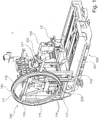
- Fig. 1 shows by way of example a system 1 for changing and inserting or presenting tools in a machine tool 200 in which the tool magazine 110 is configured by way of example as a wheel magazine.
- the machine tool 200 is equipped, for example, with a tool-carrying work spindle 202.
- the machine tool 200 has a machine bed 201 on which a workpiece clamping table can be arranged.
- the machine tool 200 may comprise one or more linear axes, preferably three linear axes (X, Y, and Z axes), in each case for driving a relative translational movement of a tool clamped on the workpiece clamping table relative to a tool clamped to the work spindle 202.
- the machine tool 200 may comprise one or more rotary or swiveling axes, preferably two or three rotary and / or swivel axes, in each case for driving a rotational relative movement of the tool clamped on the workpiece clamping table relative to the tool clamped on the work spindle 202.
- the system 1 comprises a tool magazine 100, which in the embodiment shown here has an annular wheel magazine 110 in which a plurality of tools 101 can be stored for tool storage.
- the tools 101 are supported at an end point 102 along the circumference 111 of the wheel magazine 110.
- the wheel magazine is designed as a ring-shaped hollow cylinder educated.
- tool holders 112 which can form a detachable connection with the tools 101.
- Fig. 1 are the tool holders 112 are arranged as a hole structure along the outer surface of the wheel magazine, which allows a particularly lightweight design.
- the tools are locked in the seats 112 due to centrifugal and gravitational forces.
- an active locking is realized by latching connection with the tools, in which the tools are forcibly locked in a positive connection.
- a self-holding hollow shank cone with face contact HSK
- a steep taper or Morse taper can be used.
- the tools are thus attached only at one of their longitudinal ends on the outer circumference of the wheel magazine 110, so that the tools protrude radially in the radial direction from the outer periphery of the wheel magazine to the outside.
- the longitudinal axes of the tools lie in one plane.
- the tools can be arranged extremely compact and close to each other along the circumference 111 of the wheel magazine 110.
- the wheel magazine 110 can be equipped with all common tools for chipless and cutting production.
- Fig. 1 shows to illustrate the design principle only one assembly with a tool 101.
- the wheel magazine 110 on the one hand, for example, with milling tools and on the other hand with abrasive tools (eg grinding wheels) to be equipped.
- the wheel magazine is mounted by way of example by means of a triangular frame 115, at the three end points of which an impeller 116 is arranged in each case.
- a four- or multi-point bearing is possible.
- the wheel magazine can also be supported by a central axis.
- the rotation of the wheel magazine 110 via a chain drive wherein in Fig. 1 only the drive chain 117 is shown.
- the wheel magazine 110 can also be driven directly via a pinion or via frictional engagement.
- the system 1 further comprises an exemplary horizontally movable manipulator 120 for removing the tools 101 from the tool magazine 100 so that they can be supplied to the tool spindle 202 of the machine tool 200.
- the manipulator 120 can be moved, for example, horizontally between the work spindle 202 and the wheel magazine 110.
- the manipulator 120 illustratively includes a dual gripper 121 having two gripper portions for gripping a tool interface 102 of a tool 101 (e.g., on a gripper groove).
- the machine tool 200 may be a known from the prior art machine tool for cutting or non-cutting production. Particularly advantageous is the system 1 for changing and inserting or presenting tools for universal machining centers, since they must be flexibly equipped with many different tools.
- An arrangement which is as compact as possible is achieved when the tool magazine 100 is attached laterally to the bed 201 and frame 203 in an upright position in order to allow short feed paths of the manipulator 120 to the spindle 202. Due to the possibility of an upright positioning of the wheel magazines 110, the tool changing system can almost always be positioned as close as possible to the spindle, even with different frames and bed shapes.
- the manipulator 120 from the tool magazine 100 is arranged on the outside, ie outside the circumference of the wheel magazine 110 with respect to the unloaded wheel magazine 110, so that it the tools 101 in the direction of the rotary axis of the wheel magazine and / or in the radial direction from the wheel magazine 110 to the outside can take.
- the manipulator schematically shown here comprises a first linear axis, which is adapted to move the manipulator in the direction of the rotary axis of the wheel magazine, that is in the lateral direction to the wheel magazine to perform a horizontal movement between the spindle 202 and wheel magazine 110.
- the manipulator 120 may also have a second linear axis, which is adapted to move the manipulator in the change position on the wheel magazine in the radial direction.
- the manipulator 120 is designed to remove the tools 101 in the illustrated embodiment as a sword changer with double gripper 121, with a left-side and a right-side recording.
- the double gripper 121 allows simultaneous recording of the last used tool and the subsequently required tool, so that a tool exchange with only one horizontal movement of the manipulator 120 between the spindle 202 and tool magazine 110 is possible.
- the tool magazine 100 can optionally be equipped with one or more wheel magazines 110.
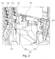
- Fig. 2 schematically shows a detail view of a system for changing and inserting or tools on a machine tool according to an exemplary embodiment of a machine tool.
- Fig. 2 shows, by way of example, two wheel magazines 110 arranged in parallel, at the circumferential tool locations of which tool interfaces 102 (for example, without tools) are held, and the manipulator 120 with the exemplary double gripper 121 (tool gripper).
- a light grid receiver 141 of a tool diameter measuring device 140 which is arranged between the work spindle 202 and the wheel magazine or magazines 110, is arranged on the frame 119 holding the wheel magazines 110.
- a light grating transmitter 142 of the tool diameter measuring device 140 is arranged on the horizontally movable manipulator 120.
- the light grating receiver 141 is exemplarily arranged stationarily on the frame 119 holding the wheel magazines 110 and the light grating transmitter 142 of the tool diameter measuring device 140 is arranged on the movable manipulator 120 by way of example, however, in other embodiments the light grating transmitter 142 the tool diameter measuring device 140 may also be arranged stationarily on the frame 119 holding the wheel magazines 110 and the light grating receiver 141 may be arranged on the movable manipulator 120. In other embodiments, too Light grating receiver 141 and light grid transmitter 142 may be arranged stationarily opposite, such that the manipulator 120 with the tool gripper 121 between light grating receiver 141 and light grating transmitter 142 is movable through.
- the light grating transmitter 142 may emit visible or invisible light (e.g., in the infrared region, and the light grating receiver 141 is configured to detect the light of the grating transmitter 142.
- Fig. 3 schematically shows a front view of a system for changing and inserting tools on a machine tool according to an exemplary embodiment of a machine tool.
- Fig. 3 is on the tool gripper 121 of the manipulator 120 by way of example held a grinding wheel as a tool 101.
- the surface covered in plan view of the light grating receiver 141 and light grating transmitter 142 of the tool diameter measuring device 140 is exemplary in the horizontal direction of the tool magazines 110 to the work spindle 202 of the machine tool 202 in the horizontal direction is traversed by a lower portion of the tool 101 and the grinding wheel.
- a measurement of the tool diameter measuring device 140 takes place at a predetermined position, in particular when the movable part (ie in FIG Fig. 2 eg the light grid transmitter 142) directly to the stationary part (ie in Fig. 2 Eg the light grid receiver 141) is opposite.
- the measuring position is exemplified by a position sensor 143, e.g. can be configured as an induction sensor, determined, and via a movable sensor portion 144, which is arranged on the manipulator 120 and is moved with the manipulator 120, can be detected when the manipulator 120 is positioned at the measuring position.
- a position sensor 143 e.g. can be configured as an induction sensor, determined, and via a movable sensor portion 144, which is arranged on the manipulator 120 and is moved with the manipulator 120, can be detected when the manipulator 120 is positioned at the measuring position.
- the diameter measurement of the tool 110 can be carried out at the measuring position when the manipulator 120 passes through, exactly at a time when it is detected via the movable sensor part 144 and the position sensor 143, that the manipulator is positioned at the measuring position or the manipulator 120 can be stopped when it is detected via the movable sensor part 144 and the position sensor 143 that the manipulator is positioned at the measuring position to the diameter measurement of the tool 110 at the measuring position perform with stopped manipulator 120.
- the diameter measurement of the tool 110 can be performed during replacement of a tool 101 on the work spindle 202, so that additional tool life on the machine tool can advantageously be avoided, as is described, for example. the case would be if the diameter measurement were performed at a designated location in the workspace or on the work spindle. In addition, it is advantageously possible to avoid additional sensors or cameras in the working space of the machine tool 200.
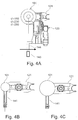
- Figs. 4A, 4B and 4C schematically illustrate a diameter measurement of a tool on a system for changing and loading tools on a machine tool according to an exemplary embodiment on a machine tool.
- the manipulator 120 in the Fig. 4A positioned in the measuring position and thus the movable sensor part 144 is positioned on the position sensor 143 and the position sensor 143 detects that the manipulator 120 is positioned at the measuring position.
- the tool 101 removed from the tool magazine 110 is held on the gripper section of the tool gripper 121 in such a way that the tool 101 (grinding wheels of different diameters are shown) on the measuring surface between the light grating receiver 141 and the light grating transmitter 142 is the tool diameter -Messvorraum 140 is positioned.
- the tool diameter measuring device 140 can thus be activated at this measuring position and the diameter of the tool 101 measured, for example by determining the degree of overlap of the tool 101 with the measuring surface between the light grating receiver 141 and the light grating transmitter 142 of the tool diameter measuring device 140.
- Fig. 4B shows a lower degree of coverage of the tool 101 with the measuring surface between the light grating receiver 141 and the light grating transmitter 142 of the tool diameter measuring device 140 due to a smaller tool diameter of a smaller grinding wheel
- Fig. 4C shows a greater degree of coverage of the tool 101 with the measuring surface between the light grating receiver 141 and the light grating transmitter 142 of the tool diameter measuring device 140 due to a larger tool diameter of a larger grinding wheel.
- light grating receivers 141 and / or light grating transmitters 142 of the tool diameter measuring device 140 can be arranged in a respective transparent housing (eg made of plastic or glass), the advantage being that they are then protected from spray water (eg cooling fluid ) are protected.
- a respective transparent housing eg made of plastic or glass
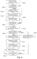
- Fig. 5 shows an exemplary flowchart of a tool change according to an embodiment.
- a tool change is instructed. This can be done on the basis of an NC program running or being executed by the machine control, or on the basis of a command from an operator at the control panel or at the machine control of the machine tool.
- a step S502 it is checked whether a tool type and / or a tool diameter is pre-stored for the tool to be removed. If this is not the case, the operator may be prompted in a step S503 to enter a diameter and / or tool type on the control panel or on the machine control of the machine tool (operator inquiry tool diameter). This is particularly advantageous in grinding tools or grinding wheels.
- a step S504 the manipulator 120 moves to the tool magazine, which holds the tool to be removed and removes the tool to be loaded.
- This may be a milling or drilling tool, or it may also be a grinding tool, such as eg be a grinding wheel.
- the manipulator 120 moves with the tool held in the tool gripper 121 of the manipulator 120 in the direction of the work spindle 202 to the measuring position between the tool magazine and work spindle; Step S505.
- the tool diameter measurement can be carried out at the measuring position between the tool magazine and work spindle in the tool changing process, so that additional service life can be avoided.
- the tool diameter measurement is advantageously carried out in the already scheduled non-productive time of the tool change.
- step S506 is YES
- the measuring device 140 is activated.
- the manipulator 120 can stop briefly or drive through the measuring point when the measuring device 140 is activated.
- step S507 the measurement or determination of the tool diameter of the tool 101 to be loaded takes place at the measuring position by means of the tool diameter measuring device 140, in particular by way of example the light grating receiver 141 and the light grating transmitter 142 of the tool diameter measuring device 140; see in particular Figs. 4A to 4C ,
- step S508 it is determined whether the measured tool diameter (actual diameter) corresponds to the predetermined preset, pre-stored or operator input diameter (target diameter). Alternatively, it may be determined whether the measured or determined tool diameter (actual diameter) falls within a predetermined, pre-set, pre-stored or operator-entered, permissible diameter range.
- step S508 If the check in step S508 is negative, a machining stop on the machine tool can be carried out in a step S509 and / or a warning can be issued to the operator.
- step S508 If the check in step S508 is positive and the measured tool diameter is equal to the predetermined preset, pre-stored or operator entered diameter or diameter range, machining with the workpiece may be enabled.
- an allowable maximum speed S_MAX be set in step S510 on the basis of the tool diameter measured or determined in step S507.
- permissible maximum speeds may be pre-stored in the machine control on the basis of tool diameters and / or tool diameter ranges, wherein larger tool diameters are preferably associated with smaller permissible maximum speeds and smaller tool diameters are preferably associated with larger permissible maximum speeds.
- allowable maximum speeds may be set based on a tool type such that e.g. Grinding tools are associated with smaller allowable maximum speeds than tools with certain cutting edge, such. Milling or drilling tools.
- step S511 the manipulator 120 then moves to the work spindle 202 and performs on the work spindle 202 the tool change in step S512, wherein the measured in step S507 tool 101 on the work spindle 202 is replaced (and optionally there is taken there previously recorded tool to again supplied to the tool magazine).
- step S513 the workpiece machining can be carried out with the substitute tool, wherein in a step S514 it is always checked whether the spindle rotational speed remains below the maximum permissible rotational speed S_MAX, which was set in step S510.
- a machining stop is effected in step S509 and a warning is issued to the operator.
- the checking of the steps S508 and / or S514, which can each lead to a processing stop and / or to a warning to the operator, can be carried out by two redundantly side-by-side devices. So it is e.g. Advantageously possible that the control device or in particular PLC (Program Logic Control, or PLC, programmable logic controller) of the machine tool 200 performs steps S508 and / or S514 and also performs a second, independent safety device steps S508 and / or S514.
- PLC Program Logic Control
- a tool diameter measuring apparatus having a light grid transmitter and a light grid receiver has been proposed.
- the present invention is not limited to tool diameter measuring devices utilizing light curtain transmitters and light curtain receivers. Rather, other optical tool diameter measuring devices may be proposed, e.g. with one or more light barriers or with one or more cameras for the analysis of the tool diameter by optical measurement.
- a system for changing and inserting tools on a machine tool and a machine tool with such a system can be proposed, which efficiently, without downtime and with the required safety allows to use both milling and drilling tools as well as grinding tools on the machine tool.
Abstract
Die vorliegende Erfindung betrifft ein System zum Wechseln und Einlegen bzw. Vorlegen von Werkzeugen an einer Werkzeugmaschine 200, umfassend: eine Werkzeugwechselvorrichtung mit einem Manipulator 120, der dazu eingerichtet ist, in einem automatischen Werkzeugwechselvorgang ein einzuwechselndes Werkzeug 101 aus einem Werkzeugmagazin 110 der Werkzeugmaschine 200 an einer Entnahmeposition zu entnehmen und einer Arbeitsspindel 202 der Werkzeugmaschine an einer Werkzeugwechselposition zu übergeben, und eine Werkzeugdurchmesser-Messvorrichtung 140, die dazu eingerichtet ist, einen Werkzeugdurchmesser bzw. Werkzeugradius des von dem Manipulator 120 aus dem Werkzeugmagazin 110 der Werkzeugmaschine 200 entnommenen einzuwechselnden Werkzeugs 101 zu bestimmen.The present invention relates to a system for changing and loading or presenting tools on a machine tool 200, comprising: a tool changing device with a manipulator 120, which is adapted, in an automatic tool changing operation, to load a tool 101 to be loaded from a tool magazine 110 of the machine tool 200 a tooling diameter measuring device 140, which is adapted to a tool diameter or tool radius of the 101 to be loaded from the tool magazine 110 of the machine tool 200 to be loaded tool 101 to a removal position and a work spindle 202 of the machine tool at a tool change position determine.
Description
Die vorliegende Erfindung betrifft ein System zum Wechseln und Einlegen bzw. Vorlegen von Werkzeugen an einer Werkzeugmaschine und eine Werkzeugmaschine mit einem derartigen System.The present invention relates to a system for changing and loading tools on a machine tool and a machine tool with such a system.
Aus der
Die Werkzeugmaschine umfasst z.B. mehrere Linear- und/oder Schwenk- bzw. Rundachsen zur Steuerung einer Relativbewegung eines an der Arbeitsspindel der Werkzeugmaschine aufgenommenen Werkzeugs relativ zu einem an der Werkzeugmaschine eingespannten Werkstück.The machine tool includes e.g. a plurality of linear and / or pivoting or rotary axes for controlling a relative movement of a tool received on the work spindle of the machine tool relative to a workpiece clamped on the machine tool.
Hierbei war es bisher bekannt, für Fräs-/Bohrbearbeitung andere Werkzeugmaschinen vorzusehen, z.B. Fräsmaschinen, Fräs-/Drehmaschinen, Universal-Werkzeugmaschinen und Bearbeitungszentren, als für Schleifbearbeitungen, für die bisher speziell für die Schleifbearbeitung vorgesehene Spezialmaschinen bzw. Schleifmaschinen vorgesehen waren.It has hitherto been known to provide other machine tools for milling / drilling operations, e.g. Milling machines, milling / lathes, universal machine tools and machining centers, as for grinding operations, for which special machines or grinding machines previously intended for grinding were intended.
Nunmehr ist es jedoch vorgesehen, die für Fräsbearbeitung eingerichteten Werkzeugmaschinen ebenfalls für die Schleifbearbeitung einzurichten, so dass Werkzeugmaschinen mit Werkzeugwechselvorrichtungen vorgesehen sind, die sowohl Fräswerkzeuge als auch Schleifwerkzeuge an der Werkzeugmaschine einsetzen können, so dass Fräs- und Schleifbearbeitungen an derselben Werkzeugmaschine und insbesondere ohne dazwischenliegende Standzeiten durchgeführt werden können. Hierfür wird z.B. in der
Hierbei ergibt sich die zugrundeliegende Aufgabe, ein System zum Wechseln und Einlegen bzw. Vorlegen von Werkzeugen an einer Werkzeugmaschine und eine Werkzeugmaschine mit einem solchen System zu schaffen, die es effizient, ohne Stillstandzeiten und mit der erforderlichen Sicherheit ermöglicht, an der Werkzeugmaschine sowohl Fräs- und Bohrwerkzeuge als auch Schleifwerkzeuge einzusetzen.In this case, the underlying object is to provide a system for changing and inserting or presenting tools on a machine tool and a machine tool with such a system, which allows efficient, without downtime and with the required safety, on the machine tool both milling and and drilling tools as well as grinding tools.
Zur Lösung der vorstehenden Aufgabe wird ein System zum Wechseln und Einlegen bzw. Vorlegen von Werkzeugen an einer Werkzeugmaschine gemäß Anspruch 1 und eine Werkzeugmaschine mit einem solchen System vorgeschlagen. Abhängige Ansprüche betreffen bevorzugte Ausführungsbeispiele der Erfindung.To achieve the above object, a system for changing and inserting or presenting tools on a machine tool according to
Gemäß einem Aspekt wird ein System zum Wechseln und Einlegen bzw. Vorlegen von Werkzeugen an einer Werkzeugmaschine vorgeschlagen, umfassend eine Werkzeugwechselvorrichtung mit einem Manipulator, der dazu eingerichtet ist, in einem automatischen Werkzeugwechselvorgang ein einzuwechselndes Werkzeug aus einem Werkzeugmagazin der Werkzeugmaschine an einer Entnahmeposition zu entnehmen und einer Arbeitsspindel der Werkzeugmaschine an einer Werkzeugwechselposition zu übergeben, und eine Werkzeugdurchmesser-Messvorrichtung, die dazu eingerichtet ist, einen Werkzeugdurchmesser bzw. Werkzeugradius des von dem Manipulator aus dem Werkzeugmagazin der Werkzeugmaschine entnommenen einzuwechselnden Werkzeugs zu bestimmen.According to one aspect, a system for changing and inserting or presenting tools on a machine tool is proposed, comprising a tool changing device with a manipulator, which is adapted to remove in an automatic tool changing operation a tool to be loaded from a tool magazine of the machine tool at a removal position and a work spindle of the machine tool at a tool change position, and a tool diameter measuring device adapted to to determine a tool diameter or tool radius of the tool to be loaded, which has been removed from the tool magazine of the machine tool by the manipulator.
In einem zweckmäßigen Ausführungsbeispiel ist der Manipulator dazu eingerichtet, zwischen der Entnahmeposition des Werkzeugmagazins der Werkzeugmaschine und der Werkzeugwechselposition zu verfahren.In an expedient exemplary embodiment, the manipulator is set up to move between the removal position of the tool magazine of the machine tool and the tool change position.
In einem zweckmäßigen Ausführungsbeispiel ist die Werkzeugdurchmesser-Messvorrichtung dazu eingerichtet, den Werkzeugdurchmesser bzw. Werkzeugradius des von dem Manipulator aus dem Werkzeugmagazin der Werkzeugmaschine entnommenen einzuwechselnden Werkzeugs an einer zwischen der Entnahmeposition und der Werkzeugwechselposition angeordneten Messposition zu bestimmen.In an expedient exemplary embodiment, the tool diameter measuring device is configured to determine the tool diameter or tool radius of the tool to be loaded, which has been removed from the tool magazine of the machine tool, at a measuring position arranged between the removal position and the tool changing position.
In einem zweckmäßigen Ausführungsbeispiel weist der Manipulator einen Werkzeuggreifer zum Greifen des einzuwechselnden Werkzeugs auf.In an expedient embodiment, the manipulator has a tool gripper for gripping the tool to be loaded.
In einem zweckmäßigen Ausführungsbeispiel ist die Werkzeugdurchmesser-Messvorrichtung dazu eingerichtet, den Werkzeugdurchmesser bzw. Werkzeugradius des von dem Manipulator an dem Werkzeuggreifer gehaltenen Werkzeugs zu bestimmen.In an expedient exemplary embodiment, the tool diameter measuring device is set up to determine the tool diameter or tool radius of the tool held by the manipulator on the tool gripper.
In einem zweckmäßigen Ausführungsbeispiel weist die Werkzeugdurchmesser-Messvorrichtung eine optische Vermessungseinrichtung zum optischen Vermessen des einzuwechselnden Werkzeugs auf, insbesondere umfassend eine Kamera und/oder ein Lichtgitter.In an expedient exemplary embodiment, the tool diameter measuring device has an optical measuring device for optically measuring the tool to be loaded, in particular comprising a camera and / or a light grid.
In einem zweckmäßigen Ausführungsbeispiel weist die Werkzeugdurchmesser-Messvorrichtung einen Lichtgitter-Empfänger und einen Lichtgitter-Sender auf.In an expedient exemplary embodiment, the tool diameter measuring device has a light grating receiver and a light grating transmitter.
In einem zweckmäßigen Ausführungsbeispiel ist der Lichtgitter-Empfänger oder der Lichtgitter-Sender an dem Manipulator der Werkzeugwechselvorrichtung angeordnet.In an expedient exemplary embodiment, the light grid receiver or the light grid transmitter is arranged on the manipulator of the tool changing device.
In einem zweckmäßigen Ausführungsbeispiel sind/ist der Lichtgitter-Sender und/oder der Lichtgitter-Empfänger an einem das Werkzeugmagazin haltenden Gestell angeordnet.In an expedient exemplary embodiment, the light grid transmitter and / or the light grid receiver are / is arranged on a frame holding the tool magazine.
In einem zweckmäßigen Ausführungsbeispiel ist/sind der Lichtgitter-Sender und/oder der Lichtgitter-Empfänger in einem jeweiligen durchsichtigen Gehäuse, insbesondere aus Kunststoff oder Glas, angeordnet.In an expedient embodiment, the light grid transmitter and / or the light grid receiver is / are arranged in a respective transparent housing, in particular made of plastic or glass.
In einem zweckmäßigen Ausführungsbeispiel umfasst das System einen Positionssensor, der dazu eingerichtet ist, festzustellen, wenn der Manipulator sich an einer Messposition befindet, und die Werkzeugdurchmesser-Messvorrichtung ist vorzugsweise dazu eingerichtet, den Werkzeugdurchmesser bzw. Werkzeugradius des von dem Manipulator aus dem Werkzeugmagazin der Werkzeugmaschine entnommenen einzuwechselnden Werkzeugs zu bestimmen, wenn der Positionssensor feststellt, dass der Manipulator sich an der Messposition befindet.In an expedient embodiment, the system includes a position sensor configured to detect when the manipulator is at a measurement position, and the tool diameter measuring device is preferably configured to adjust the tool diameter of the manipulator from the tool magazine of the machine tool to be determined when the position sensor detects that the manipulator is at the measuring position.
In einem zweckmäßigen Ausführungsbeispiel umfasst das System eine Sicherheitsvorrichtung, die dazu eingerichtet ist, auf Basis eines von der Werkzeugdurchmesser-Messvorrichtung ermittelten Werkzeugdurchmessers bzw. Werkzeugradius eine maximal zulässige Spindeldrehzahl der Arbeitsspindel für das einzuwechselnde Werkzeug zu bestimmen.In an expedient exemplary embodiment, the system comprises a safety device which is set up to determine a maximum permissible spindle rotational speed of the work spindle for the tool to be loaded on the basis of a tool diameter or tool radius determined by the tool diameter measuring device.
In einem zweckmäßigen Ausführungsbeispiel ist die Sicherheitsvorrichtung dazu eingerichtet, auf Basis des von der Werkzeugdurchmesser-Messvorrichtung ermittelten Werkzeugdurchmessers bzw. Werkzeugradius und des Werkzeugtyps eine maximal zulässige Spindeldrehzahl der Arbeitsspindel für das einzuwechselnde Werkzeug zu bestimmen.In an expedient exemplary embodiment, the safety device is set up to determine a maximum permissible spindle rotational speed of the work spindle for the tool to be loaded on the basis of the tool diameter or tool radius determined by the tool diameter measuring device and the tool type.
In einem zweckmäßigen Ausführungsbeispiel ist die Sicherheitsvorrichtung dazu eingerichtet, die Spindeldrehzahl der Arbeitsspindel bei der Bearbeitung eines Werkstücks mit dem einzuwechselnden Werkzeug zu überwachen und einen Bearbeitungsstop durchzuführen und/oder eine Warnung an einen Bediener auszugeben, wenn die überwachte Spindeldrehzahl die eingestellte maximal zulässige Spindeldrehzahl der Arbeitsspindel für das einzuwechselnde Werkzeug überschreitet.In an expedient embodiment, the safety device is configured to monitor the spindle speed of the work spindle when machining a workpiece with the tool to be loaded and to perform a machining stop and / or issue a warning to an operator if the monitored spindle speed exceeds the set maximum spindle speed of the work spindle for the tool to be loaded.
In einem zweckmäßigen Ausführungsbeispiel ist die Sicherheitsvorrichtung dazu eingerichtet, den von der Werkzeugdurchmesser-Messvorrichtung ermittelten Werkzeugdurchmesser bzw. Werkzeugradius des einzuwechselnden Werkzeugs mit einem Solldurchmesser bzw. Sollradius und/oder einem Solldurchmesserbereich bzw. Sollradiusbereich zu vergleichen, und einen Bearbeitungsstop durchzuführen und/oder eine Warnung an einen Bediener auszugeben, wenn der von der Werkzeugdurchmesser-Messvorrichtung ermittelte Werkzeugdurchmesser bzw. Werkzeugradius des einzuwechselnden Werkzeugs von dem Solldurchmesser bzw. Sollradius und/oder dem Solldurchmesserbereich bzw. Sollradiusbereich abweicht.In an expedient exemplary embodiment, the safety device is set up to compare the tool diameter or tool radius of the tool to be loaded with a set diameter or setpoint radius and / or a set diameter range or setpoint radius range, and to perform a machining stop and / or a warning output to an operator when the tool diameter or tool radius of the tool to be loaded determined by the tool diameter measuring device deviates from the nominal diameter or nominal radius and / or the nominal diameter range or nominal radius range.
Gemäß einem weiteren Aspekt wird eine Werkzeugmaschine vorgeschlagen, mit einer werkzeugtragenden Arbeitsspindel, einem Werkzeugmagazin, und einem System gemäß einem der vorstehenden Aspekte.According to a further aspect, a machine tool is proposed, comprising a tool-carrying work spindle, a tool magazine, and a system according to one of the preceding aspects.
In einem zweckmäßigen Ausführungsbeispiel ist eine Steuervorrichtung der Werkzeugmaschine mit der Werkzeugdurchmesser-Messvorrichtung verbunden und dazu eingerichtet, auf Basis eines von der Werkzeugdurchmesser-Messvorrichtung ermittelten Werkzeugdurchmessers bzw. Werkzeugradius eine maximal zulässige Spindeldrehzahl der Arbeitsspindel für das einzuwechselnde Werkzeug einzustellen.In an expedient exemplary embodiment, a control device of the machine tool is connected to the tool diameter measuring device and adapted to set a maximum permissible spindle speed of the work spindle for the tool to be loaded on the basis of a tool diameter or tool radius determined by the tool diameter measuring device.
In einem zweckmäßigen Ausführungsbeispiel ist die Steuervorrichtung der Werkzeugmaschine dazu eingerichtet, auf Basis des von der Werkzeugdurchmesser-Messvorrichtung ermittelten Werkzeugdurchmessers bzw. Werkzeugradius und des Werkzeugtyps eine maximal zulässige Spindeldrehzahl der Arbeitsspindel für das einzuwechselnde Werkzeug einzustellen.In an expedient exemplary embodiment, the control device of the machine tool is set up to set a maximum permissible spindle speed of the work spindle for the tool to be loaded on the basis of the tool diameter or tool radius determined by the tool diameter measuring device and the tool type.
In einem zweckmäßigen Ausführungsbeispiel ist die Steuervorrichtung der Werkzeugmaschine dazu eingerichtet, die Spindeldrehzahl der Arbeitsspindel bei der Bearbeitung eines Werkstücks mit dem einzuwechselnden Werkzeug zu überwachen und einen Bearbeitungsstop durchzuführen und/oder eine Warnung an einen Bediener auszugeben, wenn die überwachte Spindeldrehzahl die eingestellte maximal zulässige Spindeldrehzahl der Arbeitsspindel für das einzuwechselnde Werkzeug überschreitet.In an expedient exemplary embodiment, the control device of the machine tool is set up to monitor the spindle speed of the work spindle when machining a workpiece with the tool to be loaded and to perform a processing stop and / or to issue a warning to an operator if the monitored spindle speed exceeds the set maximum permissible spindle speed exceeds the working spindle for the tool to be loaded.
In einem zweckmäßigen Ausführungsbeispiel ist die Steuervorrichtung dazu eingerichtet, den von der Werkzeugdurchmesser-Messvorrichtung ermittelten Werkzeugdurchmesser bzw. Werkzeugradius des einzuwechselnden Werkzeugs mit einem Solldurchmesser bzw. Sollradius und/oder einem Solldurchmesserbereich bzw. Sollradiusbereich zu vergleichen, und einen Bearbeitungsstop durchzuführen und/oder eine Warnung an einen Bediener auszugeben, wenn der von der Werkzeugdurchmesser-Messvorrichtung ermittelte Werkzeugdurchmesser bzw. Werkzeugradius des einzuwechselnden Werkzeugs von dem Solldurchmesser bzw. Sollradius und/oder dem Solldurchmesserbereich bzw. Sollradiusbereich abweicht.In an expedient exemplary embodiment, the control device is set up to compare the tool diameter or tool radius of the tool to be loaded with the tool diameter measuring device with a desired diameter and / or a desired diameter range or target radius range, and to perform a machining stop and / or a warning output to an operator when the tool diameter or tool radius of the tool to be loaded determined by the tool diameter measuring device deviates from the nominal diameter or nominal radius and / or the nominal diameter range or nominal radius range.
- Fig. 1Fig. 1
- zeigt schematisch eine Perspektivansicht eines Systems zum Wechseln und Einlegen bzw. Vorlegen von Werkzeugen an einer Werkzeugmaschine gemäß einer beispielhaften Ausführungsform an einer Werkzeugmaschine;schematically shows a perspective view of a system for changing and inserting tools on a machine tool according to an exemplary embodiment of a machine tool;
- Fig. 2Fig. 2
- zeigt schematisch eine Detailansicht eines Systems zum Wechseln und Einlegen bzw. Vorlegen von Werkzeugen an einer Werkzeugmaschine gemäß einer beispielhaften Ausführungsform an einer Werkzeugmaschine;schematically shows a detail view of a system for changing and inserting tools on a machine tool according to an exemplary embodiment on a machine tool;
- Fig. 3Fig. 3
- zeigt schematisch eine Vorderansicht eines Systems zum Wechseln und Einlegen bzw. Vorlegen von Werkzeugen an einer Werkzeugmaschine gemäß einer beispielhaften Ausführungsform an einer Werkzeugmaschine;schematically shows a front view of a system for changing and inserting tools on a machine tool according to an exemplary embodiment of a machine tool;
- Figs. 4A, 4B und 4CFigs. 4A, 4B and 4C
- illustrieren schematisch eine Durchmessermessung eines Werkzeugs an einem System zum Wechseln und Einlegen bzw. Vorlegen von Werkzeugen an einer Werkzeugmaschine gemäß einer beispielhaften Ausführungsform an einer Werkzeugmaschine; undschematically illustrate a diameter measurement of a tool on a system for changing and loading tools on a machine tool according to an exemplary embodiment on a machine tool; and
- Fig. 5Fig. 5
- zeigt ein beispielhaftes Ablaufdiagram eines Werkzeugwechsels gemäß eines Ausführungsbeispiels.shows an exemplary flowchart of a tool change according to an embodiment.
Im Folgenden werden Beispiele bzw. Ausführungsbeispiele der vorliegenden Erfindung detailliert unter Bezugnahme auf die beigefügten Figuren beschrieben. Gleiche bzw. ähnliche Elemente in den Figuren können hierbei mit gleichen Bezugszeichen bezeichnet sein. Es sei hervorgehoben, dass die vorliegende Erfindung jedoch in keinster Weise auf die im Folgenden beschriebenen Ausführungsbeispiele und deren Ausführungsmerkmale begrenzt bzw. eingeschränkt ist, sondern weiterhin Modifikationen der Ausführungsbeispiele umfasst, insbesondere diejenigen, die durch Modifikationen der Merkmale der beschriebenen Beispiele bzw. durch Kombination einzelner oder mehrerer der Merkmale der beschriebenen Beispiele im Rahmen des Schutzumfanges der unabhängigen Ansprüche umfasst sind.Hereinafter, examples of embodiments of the present invention will be described in detail with reference to the accompanying drawings. Identical or similar elements in the figures can be designated by the same reference numerals. It should be understood, however, that the present invention is in no way limited or limited to the embodiments described below and the embodiments thereof, but further includes modifications of the embodiments, particularly those modified by modifications of the features of the examples described or by combination of individual or more of the features of the described examples are included within the scope of the independent claims.
Die Werkzeugmaschine 200 ist beispielhaft mit einer werkzeugtragenden Arbeitsspindel 202 ausgestattet. Zudem weist die Werkzeugmaschine 200 ein Maschinenbett 201 auf, auf dem ein Werkstückeinspanntisch anordenbar ist. Zudem kann die Werkzeugmaschine 200 eine oder mehrere Linearachsen umfassen, bevorzugt drei Linearachsen (X-, Y-, und Z-Achse) jeweils zum Antreiben einer translatorischen Relativbewegung eines auf dem Werkstückeinspanntisch eingespannten Werkzeug relativ zu einem an der Arbeitsspindel 202 eingespannten Werkzeug. Zudem kann die Werkzeugmaschine 200 eine oder mehrere Rund bzw. Schwenkachsen umfassen, bevorzugt zwei oder drei Rund- und/oder Schwenkachsen jeweils zum Antreiben einer rotatorischen Relativbewegung des auf dem Werkstückeinspanntisch eingespannten Werkzeug relativ zu dem an der Arbeitsspindel 202 eingespannten Werkzeug.The
Das System 1 umfasst ein Werkzeugmagazin 100, das in der hier gezeigten Ausführungsform über ein ringförmiges Radmagazin 110 verfügt, in dem jeweils eine Mehrzahl von Werkzeugen 101 zur Werkzeugbevorratung aufbewahrt werden können.The
Die Werkzeuge 101 sind an einem Endpunkt 102 entlang des Umfangs 111 des Radmagazins 110 gehaltert. Das Radmagazin ist als ringförmiger Hohlzylinder ausgebildet. Entlang des Umfangs 111 des Radmagazins 110, d.h. entlang der äußeren Mantelfläche befinden sich Werkzeugaufnahmen 112, die eine lösbare Verbindung mit den Werkzeugen 101 eingehen können.The
In
Die Werkzeuge sind somit nur an einem ihrer Längsenden am äußeren Umfang des Radmagazins 110 befestigt, so dass die Werkzeuge in radialer Richtung vom Außenumfang des Radmagazins nach außen strahlenförmig abstehen. Dadurch liegen die Längsachsen der Werkzeuge in einer Ebene. Dadurch können die Werkzeuge äußerst kompakt und dicht entlang des Umfangs 111 des Radmagazins 110 nebeneinander angeordnet werden.The tools are thus attached only at one of their longitudinal ends on the outer circumference of the
Das Radmagazin 110 kann mit allen gängigen Werkzeugen für die spanlose und spangebende Fertigung bestückt werden.
Das Radmagazin ist beispielhaft mittels eines Dreiecksrahmens 115 gelagert, an dessen drei Endpunkten jeweils ein Laufrad 116 angeordnet ist. Neben der hier gezeigten Dreipunktlagerung ist auch eine Vier- oder Mehrpunktlagerung möglich. Anstatt des Dreiecksrahmens 115 kann das Radmagazin auch durch eine Mittelachse gelagert werden. Die Rotation des Radmagazins 110 erfolgt über einen Kettenantrieb, wobei in
Das System 1 umfasst weiterhin einen beispielhaft horizontal verfahrbaren Manipulator 120 zur Entnahme der Werkzeuge 101 aus dem Werkzeugmagazin 100, so dass diese der Werkzeugspindel 202 der Werkzeugmaschine 200 zugeführt werden können. Hierfür ist der Manipulator 120 beispielhaft horizontal zwischen der Arbeitsspindel 202 und dem Radmagazin 110 verfahrbar. Der Manipulator 120 weist beispielhaft einen Doppelgreifer 121 auf, mit zwei Greiferabschnitten zum Greifen einer Werkzeugschnittstelle 102 eines Werkzeugs 101 (z.B. an einer Greiferrille).The
Bei der Werkzeugmaschine 200 kann es sich um eine aus dem Stand der Technik bekannte Werkzeugmaschine für die spangebende oder spanlose Fertigung handeln. Besonders vorteilhaft ist das System 1 zum Wechseln und Einlegen bzw. Vorlegen von Werkzeugen für Universalbearbeitungszentren, da diese flexibel mit vielen unterschiedlichen Werkzeugen bestückt werden müssen. Eine möglichst kompakte Anordnung wird dann erreicht, wenn das Werkzeugmagazin 100 seitlich an das Bett 201 und Gestell 203 in aufrechter Position angebracht wird, um kurze Zustellwege des Manipulators 120 zur Spindel 202 zu ermöglichen. Durch die Möglichkeit einer aufrechten Positionierung der Radmagazine 110 kann das Werkzeugwechselsystem auch bei unterschiedlichen Gestellen und Bettformen fast immer möglichst nah an der Spindel positioniert werden.The
Der Manipulator 120 aus dem Werkzeugmagazin 100 ist in Bezug auf das unbestückte Radmagazin 110 außenseitig, das heißt außerhalb des Umfangs des Radmagazins 110 angeordnet, so dass er die Werkzeuge 101 in Richtung der Rundachse des Radmagazins und/ oder in radialer Richtung vom Radmagazin 110 nach außen entnehmen kann. Der hier schematisch dargestellte Manipulator umfasst eine erste Linearachse, die dazu geeignet ist, den Manipulator in Richtung der Rundachse des Radmagazins, das heißt in seitlicher Richtung zum Radmagazin zu verfahren um eine Horizontalbewegung zwischen Spindel 202 und Radmagazin 110 auszuführen. Der Manipulator 120 kann auch eine zweite Linearachse aufweisen, die dazu geeignet ist, den Manipulator in der Wechselposition am Radmagazin in radialer Richtung zu verfahren.The
Der Manipulator 120 ist zur Entnahme der Werkzeuge 101 im gezeigten Ausführungsbeispiel als Schwertwechsler mit Doppelgreifer 121 ausgebildet, mit einer linksseitigen und einer rechtsseitigen Aufnahme. Der Doppelgreifer 121 ermöglicht die gleichzeitige Aufnahme des zuletzt genutzten Werkzeugs und des nachfolgend benötigten Werkzeugs, so dass ein Werkzeugtausch mit nur einer Horizontalbewegung des Manipulators 120 zwischen Spindel 202 und Werkzeugmagazin 110 möglich ist. Das Werkzeugmagazin 100 kann wahlweise mit einem oder mehreren Radmagazinen 110 bestückt werden.The
Beispielhaft ist an dem die Radmagazine 110 haltenden Gestell 119 ein Lichtgitter-Empfänger 141 einer Werkzeugdurchmesser-Messvorrichtung 140 angeordnet, der zwischen der Arbeitsspindel 202 und dem bzw. den Radmagazinen 110 angeordnet ist. Auf gleicher Höhe zu dem Lichtgitter-Empfänger 142 ist an dem horizontal verfahrbaren Manipulator 120 ein Lichtgitter-Sender 142 der Werkzeugdurchmesser-Messvorrichtung 140 angeordnet.By way of example, a
In diesem Ausführungsbeispiel ist der Lichtgitter-Empfänger 141 beispielhaft stationär an dem die Radmagazine 110 haltenden Gestell 119 angeordnet und der Lichtgitter-Sender 142 der Werkzeugdurchmesser-Messvorrichtung 140 ist beispielhaft an dem verfahrbaren Manipulator 120 angeordnet, jedoch kann in anderen Ausführungsbeispielen der Lichtgitter-Sender 142 der Werkzeugdurchmesser-Messvorrichtung 140 auch stationär an dem die Radmagazine 110 haltenden Gestell 119 angeordnet sein und der Lichtgitter-Empfänger 141 kann an dem verfahrbaren Manipulator 120 angeordnet sein. In weiteren Ausführungsbeispielen können auch Lichtgitter-Empfänger 141 und Lichtgitter-Sender 142 stationär gegenüberliegend angeordnet sein, derart, dass der Manipulator 120 mit dem Werkzeuggreifer 121 zwischen Lichtgitter-Empfänger 141 und Lichtgitter-Sender 142 hindurch verfahrbar ist.In this embodiment, the
Der Lichtgitter-Sender 142 kann sichtbares oder unsichtbares Licht (z.B. im Infrarot-bereich aussenden, und der Lichtgitter-Empfänger 141 ist dazu eingerichtet, das Licht des Lichtgitter-Senders 142 zu detektieren.The light
In
Hierbei ist es vorgesehen, dass eine Messung der Werkzeugdurchmesser-Messvorrichtung 140 an einer vorgegebenen Position stattfindet, insbesondere dann, wenn der bewegliche Teil (d.h. in
Die Messposition wird beispielhaft durch einen Positionssensor 143, der z.B. als Induktionssensor ausgebildet sein kann, bestimmt, und über einen beweglichen Sensorteil 144, der an dem Manipulator 120 angeordnet ist und mit dem Manipulator 120 mit verfahren wird, kann detektiert werden, wenn der Manipulator 120 an der Messposition positioniert ist.The measuring position is exemplified by a
Hierbei kann die Durchmesser-Messung des Werkzeugs 110 an der Messposition bei durchfahrendem Manipulator 120 durchgeführt werden, genau zu einem Zeitpunkt, wenn über den beweglichen Sensorteil 144 und den Positionssensor 143 detektiert wird, dass der Manipulator an der Messposition positioniert ist, oder der Manipulator 120 kann angehalten werden, wenn über den beweglichen Sensorteil 144 und den Positionssensor 143 detektiert wird, dass der Manipulator an der Messposition positioniert ist, um die Durchmesser-Messung des Werkzeugs 110 an der Messposition bei angehaltenem Manipulator 120 durchzuführen.In this case, the diameter measurement of the
In beiden Fällen kann die Durchmesser-Messung des Werkzeugs 110 während des Einwechselns eines Werkzeugs 101 an der Arbeitsspindel 202 durchgeführt werden, so dass zusätzliche Standzeiten an der Werkzeugmaschine vorteilhaft vermieden werden können, wie es z.B. der Fall wäre, wenn die Durchmesser-Messung an einer designierten Stelle im Arbeitsraum oder an der Arbeitsspindel durchgeführt würde. Zudem ist es vorteilhaft möglich, zusätzliche Sensoren oder Kameras im Arbeitsraum der Werkzeugmaschine 200 zu vermeiden.In both cases, the diameter measurement of the
Beispielhaft ist der Manipulator 120 in der
In der Messposition ist das aus dem Werkzeugmagazin 110 entnommene Werkzeug 101 an dem Greiferabschnitt des Werkzeuggreifers 121 derart gehalten, dass das Werkzeug 101 (beispielhaft sind Schleifscheiben verschiedener Durchmesser gezeigt) an der Messfläche zwischen dem Lichtgitter-Empfänger 141 und dem Lichtgitter-Sender 142 der Werkzeugdurchmesser-Messvorrichtung 140 positioniert ist.In the measuring position, the
An dieser Messposition kann somit die Werkzeugdurchmesser-Messvorrichtung 140 aktiviert werden und den Durchmesser des Werkzeugs 101 vermessen, indem z.B. der Überdeckungsgrad des Werkzeugs 101 mit der Messfläche zwischen dem Lichtgitter-Empfänger 141 und dem Lichtgitter-Sender 142 der Werkzeugdurchmesser-Messvorrichtung 140 ermittelt wird.The tool
In Ausführungsbeispielen der Erfindung können Lichtgitter-Empfänger 141 und/oder Lichtgitter-Sender 142 der Werkzeugdurchmesser-Messvorrichtung 140 in einem jeweiligen durchsichtigen Gehäuse (z.B. aus Kunststoff oder Glas) angeordnet sein, wobei sich der Vorteil ergibt, dass diese dann vor Spritzwasser (z.B. Kühlflüssigkeit) geschützt sind.In exemplary embodiments of the invention, light
In einem Schritt S501 wird ein Werkzeugwechsel instruiert. Dies kann auf Basis eines ablaufenden bzw. von der Maschinensteuerung durchgeführten NC-Programms geschehen, oder auf Basis eines Befehls eines Bedieners am Bedienpult oder an der Maschinensteuerung der Werkzeugmaschine.In a step S501, a tool change is instructed. This can be done on the basis of an NC program running or being executed by the machine control, or on the basis of a command from an operator at the control panel or at the machine control of the machine tool.
In einem Schritt S502 wird überprüft, ob für das zu entnehmende Werkzeug ein Werkzeugtyp und/oder ein Werkzeugdurchmesser vorgespeichert ist. Falls dem nicht so ist, kann der Bediener in einem Schritt S503 aufgefordert sein, am Bedienpult oder an der Maschinensteuerung der Werkzeugmaschine einen Durchmesser und/oder Werkzeugtyp einzugeben (Bedienerabfrage Werkzeugdurchmesser). Dies ist insbesondere bei Schleifwerkzeugen bzw. Schleifscheiben vorteilhaft.In a step S502 it is checked whether a tool type and / or a tool diameter is pre-stored for the tool to be removed. If this is not the case, the operator may be prompted in a step S503 to enter a diameter and / or tool type on the control panel or on the machine control of the machine tool (operator inquiry tool diameter). This is particularly advantageous in grinding tools or grinding wheels.
In einem Schritt S504 verfährt der Manipulator 120 zu dem Werkzeugmagazin, das das zu entnehmende Werkzeug hält und entnimmt das einzuwechselnde Werkzeug. Dies kann ein Fräs- oder Bohrwerkzeug sein, oder es kann auch ein Schleifwerkzeug, wie z.B. eine Schleifscheibe sein. Dann verfährt der Manipulator 120, nachdem das Werkzeug aus dem Magazin entnommen wurde mit dem in dem Werkzeuggreifer 121 des Manipulators 120 gehaltenen Werkzeug in Richtung der Arbeitsspindel 202 zu der Messposition zwischen Werkzeugmagazin und Arbeitsspindel; Schritt S505.In a step S504, the
Dies hat den Vorteil, dass die Werkzeugdurchmesser-Vermessung an der Messposition zwischen Werkzeugmagazin und Arbeitsspindel im Werkzeugwechselvorgang erfolgen kann, so dass zusätzliche Standzeiten vermieden werden können. Die Werkzeugdurchmesser-Vermessung erfolgt nämlich vorteilhaft in der bereits eingeplanten Nebenzeit des Werkzeugwechsels.This has the advantage that the tool diameter measurement can be carried out at the measuring position between the tool magazine and work spindle in the tool changing process, so that additional service life can be avoided. Namely, the tool diameter measurement is advantageously carried out in the already scheduled non-productive time of the tool change.
Sobald der Manipulator 120 an der Messposition ankommt, wobei dies durch den Positionssensor 143 detektiert wird (Schritt S506 ergibt JA), wird die Messvorrichtung 140 aktiviert. Hierbei kann der Manipulator 120 kurz anhalten oder bei aktivierter Messvorrichtung 140 durch den Messpunkt durchfahren.As soon as the
Im Schritt S507 erfolgt an der Messposition die Vermessung bzw. Bestimmung des Werkzeugdurchmessers des einzuwechselnden Werkzeugs 101 mittels der Werkzeugdurchmesser-Messvorrichtung 140, insbesondere beispielhaft mittels dem Lichtgitter-Empfänger 141 und dem Lichtgitter-Sender 142 der Werkzeugdurchmesser-Messvorrichtung 140; siehe hierzu insbesondere
Im Schritt S508 wird bestimmt, ob der gemessene bzw. bestimmte Werkzeugdurchmesser (Istdurchmesser) dem vorbestimmten, voreingestellten, vorgespeicherten oder vom Bediener eingegebenen Durchmesser (Solldurchmesser) entspricht. Alternativ kann bestimmt werden, ob der gemessene bzw. bestimmte Werkzeugdurchmesser (Istdurchmesser) in einen vorbestimmten, voreingestellten, vorgespeicherten oder vom Bediener eingegebenen, zulässigen Durchmesserbereich fällt.In step S508, it is determined whether the measured tool diameter (actual diameter) corresponds to the predetermined preset, pre-stored or operator input diameter (target diameter). Alternatively, it may be determined whether the measured or determined tool diameter (actual diameter) falls within a predetermined, pre-set, pre-stored or operator-entered, permissible diameter range.
Falls die Überprüfung in Schritt S508 negativ ist, kann in einem Schritt S509 ein Bearbeitungsstop an der Werkzeugmaschine erfolgen und/oder eine Warnung an den Bediener ausgegeben werden.If the check in step S508 is negative, a machining stop on the machine tool can be carried out in a step S509 and / or a warning can be issued to the operator.
Falls die Überprüfung in Schritt S508 positiv ist und der gemessene bzw. bestimmte Werkzeugdurchmesser dem vorbestimmten, voreingestellten, vorgespeicherten oder vom Bediener eingegebenen Durchmesser bzw. Durchmesserbereich entspricht, kann die Bearbeitung mit dem Werkstück freigegeben werden.If the check in step S508 is positive and the measured tool diameter is equal to the predetermined preset, pre-stored or operator entered diameter or diameter range, machining with the workpiece may be enabled.
Hierzu ist es, insbesondere bei Schleifwerkzeugen, bevorzugt, dass im Schritt S510 auf Basis des in Schritt S507 gemessenen bzw. bestimmten Werkzeugdurchmessers eine zulässige Maximaldrehzahl S_MAX eingestellt wird.For this purpose, in particular in the case of grinding tools, it is preferred that an allowable maximum speed S_MAX be set in step S510 on the basis of the tool diameter measured or determined in step S507.
Hierbei können in der Maschinensteuerung auf Basis von Werkzeugdurchmessern und/oder Werkzeugdurchmesserbereichen zulässige Maximaldrehzahlen vorgespeichert sein, wobei größere Werkzeugdurchmesser bevorzugt kleineren zulässigen Maximaldrehzahlen zugeordnet sind und kleinere Werkzeugdurchmesser bevorzugt größeren zulässigen Maximaldrehzahlen zugeordnet sind.In this case, permissible maximum speeds may be pre-stored in the machine control on the basis of tool diameters and / or tool diameter ranges, wherein larger tool diameters are preferably associated with smaller permissible maximum speeds and smaller tool diameters are preferably associated with larger permissible maximum speeds.
Außerdem können zulässige Maximaldrehzahlen auf Basis eines Werkzeugtyps eingestellt werden, so dass z.B. Schleifwerkzeuge kleineren zulässigen Maximaldrehzahlen zugeordnet sind, als Werkzeuge mit bestimmter Schneide, wie z.B. Fräs- oder Bohrwerkzeugen.In addition, allowable maximum speeds may be set based on a tool type such that e.g. Grinding tools are associated with smaller allowable maximum speeds than tools with certain cutting edge, such. Milling or drilling tools.
Dies hat den Vorteil, dass direkt bei dem Werkzeugwechselvorgang der Durchmesser des Werkzeugs überprüft werden kann und abhängig von Durchmesser und Werkzeugtyp eine passende maximal zulässige Drehzahl einstellbar ist, die den für den bestimmten Werkzeugtyp passenden Sicherheitsbestimmungen entspricht. Somit ist es vorteilhaft möglich, an derselben Werkzeugmaschine Fräs- bzw. Bohrwerkzeuge einzuwechseln, als auch Schleifwerkzeuge, ohne Sicherheitseinbußen.This has the advantage that the diameter of the tool can be checked directly during the tool changing process and, depending on the diameter and tool type, a suitable maximum permissible rotational speed can be set that corresponds to the safety regulations that are appropriate for the particular tool type. Thus, it is advantageously possible to use the same machine tool milling or drilling tools, as well as grinding tools, without sacrificing security.
Im Schritt S511 verfährt der Manipulator 120 dann zur Arbeitsspindel 202 und vollführt an der Arbeitsspindel 202 den Werkzeugwechsel in Schritt S512, wobei das in Schritt S507 vermessene Werkzeug 101 an der Arbeitsspindel 202 eingewechselt wird (und gegebenenfalls ein dort bisher aufgenommenes Werkzeug entnommen wird, um wieder dem Werkzeugmagazin zugeführt zu werden).In step S511, the
Nach Einwechseln des Werkzeugs 101 an der Arbeitsspindel 202 kann in einem Schritt S513 die Werkstückbearbeitung mit dem eingewechselten Werkzeug erfolgen, wobei in einem Schritt S514 stets überprüft wird, ob die Spindeldrehzahl unter der maximal zulässigen Drehzahl S_MAX bleibt, die in Schritt S510 eingestellt wurde.After replacing the
Falls die Spindeldrehzahl die maximal zulässige Drehzahl S_MAX überschreitet, wird in Schritt S509 ein Bearbeitungsstop herbeigeführt und eine Warnung an den Bediener ausgegeben.If the spindle rotational speed exceeds the maximum allowable rotational speed S_MAX, a machining stop is effected in step S509 and a warning is issued to the operator.
Somit kann vorteilhaft sichergestellt werden, dass die Spindeldrehzahl nicht die maximal für den jeweiligen Werkzeugdurchmesser zulässige Drehzahl überschreitet, insbesondere bei Schleifwerkzeugen bzw. Schleifscheiben.Thus, it can be advantageously ensured that the spindle speed does not exceed the maximum allowable for the respective tool diameter speed, especially in grinding tools or grinding wheels.
Um die Sicherheit noch zu vergrößern, kann die Überprüfung der Schritte S508 und/oder S514, die jeweils zu einem Bearbeitungsstop und/oder zu einer Warnung an den Bediener führen können, von zwei redundant nebeneinander arbeitenden Vorrichtungen durchgeführt werden. So ist es z.B. vorteilhaft möglich, dass die Steuervorrichtung bzw. insbesondere PLC (Program Logic Control; bzw. SPS, speicherprogrammierbare Steuerung) der Werkzeugmaschine 200 die Schritte S508 und/oder S514 durchführt und zudem eine zweite, unabhängige Sicherheitsvorrichtung die Schritte S508 und/oder S514 durchführt.In order to increase the security still further, the checking of the steps S508 and / or S514, which can each lead to a processing stop and / or to a warning to the operator, can be carried out by two redundantly side-by-side devices. So it is e.g. Advantageously possible that the control device or in particular PLC (Program Logic Control, or PLC, programmable logic controller) of the
In den vorstehenden Ausführungsbeispielen wurde eine Werkzeugdurchmesser-Messvorrichtung mit einem Lichtgitter-Sender und einem Lichtgitter-Empfänger vorgeschlagen. Jedoch ist die vorliegende Erfindung nicht auf Lichtgitter-Sender und Lichtgitter-Empfänger verwendende Werkzeugdurchmesser-Messvorrichtungen beschränkt. Vielmehr können weitere optisch arbeitende Werkzeugdurchmesser-Messvorrichtungen vorgeschlagen werden, z.B. mit einer oder mehrerer Lichtschranken oder auch mit einer oder mehreren Kameras zur Analyse des Werkzeugdurchmessers durch optische Vermessung.In the above embodiments, a tool diameter measuring apparatus having a light grid transmitter and a light grid receiver has been proposed. However, the present invention is not limited to tool diameter measuring devices utilizing light curtain transmitters and light curtain receivers. Rather, other optical tool diameter measuring devices may be proposed, e.g. with one or more light barriers or with one or more cameras for the analysis of the tool diameter by optical measurement.
Zusammenfassend kann ein System zum Wechseln und Einlegen bzw. Vorlegen von Werkzeugen an einer Werkzeugmaschine und eine Werkzeugmaschine mit einem solchen System vorgeschlagen werden, die es effizient, ohne Stillstandzeiten und mit der erforderlichen Sicherheit ermöglicht, an der Werkzeugmaschine sowohl Fräs- und Bohrwerkzeuge als auch Schleifwerkzeuge einzusetzen.In summary, a system for changing and inserting tools on a machine tool and a machine tool with such a system can be proposed, which efficiently, without downtime and with the required safety allows to use both milling and drilling tools as well as grinding tools on the machine tool.
Claims (15)
der Manipulator dazu eingerichtet ist, zwischen der Entnahmeposition des Werkzeugmagazins der Werkzeugmaschine und der Werkzeugwechselposition zu verfahren, und
die Werkzeugdurchmesser-Messvorrichtung dazu eingerichtet ist, den Werkzeugdurchmesser bzw. Werkzeugradius des von dem Manipulator aus dem Werkzeugmagazin der Werkzeugmaschine entnommenen einzuwechselnden Werkzeugs an einer zwischen der Entnahmeposition und der Werkzeugwechselposition angeordneten Messposition zu bestimmen.System according to claim 1, characterized in that
the manipulator is adapted to move between the removal position of the tool magazine of the machine tool and the tool change position, and
the tool diameter measuring device is set up to determine the tool diameter or tool radius of the tool to be loaded, which has been removed from the tool magazine of the machine tool, at a measuring position arranged between the removal position and the tool changing position.
die Sicherheitsvorrichtung dazu eingerichtet ist, auf Basis des von der Werkzeugdurchmesser-Messvorrichtung ermittelten Werkzeugdurchmessers bzw. Werkzeugradius und des Werkzeugtyps eine maximal zulässige Spindeldrehzahl der Arbeitsspindel für das einzuwechselnde Werkzeug zu bestimmen.System according to claim 3, characterized in that
the safety device is adapted to determine, on the basis of the tool diameter or tool radius determined by the tool diameter measuring device and the tool type, a maximum permissible spindle speed of the work spindle for the tool to be loaded.
die Sicherheitsvorrichtung dazu eingerichtet ist, die Spindeldrehzahl der Arbeitsspindel bei der Bearbeitung eines Werkstücks mit dem einzuwechselnden Werkzeug zu überwachen und einen Bearbeitungsstop durchzuführen und/oder eine Warnung an einen Bediener auszugeben, wenn die überwachte Spindeldrehzahl die eingestellte maximal zulässige Spindeldrehzahl der Arbeitsspindel für das einzuwechselnde Werkzeug überschreitet.System according to claim 3 or 4, characterized in that
the safety device is adapted to monitor the spindle speed of the work spindle when machining a workpiece with the tool to be loaded and to perform a machining stop and / or issue a warning to an operator if the monitored spindle speed is the set maximum allowable spindle speed of the work spindle for the tool to be loaded exceeds.
die Sicherheitsvorrichtung dazu eingerichtet ist, den von der Werkzeugdurchmesser-Messvorrichtung ermittelten Werkzeugdurchmesser bzw. Werkzeugradius des einzuwechselnden Werkzeugs mit einem Solldurchmesser bzw. Sollradius und/oder einem Solldurchmesserbereich bzw. Sollradiusbereich zu vergleichen, und einen Bearbeitungsstop durchzuführen und/oder eine Warnung an einen Bediener auszugeben, wenn der von der Werkzeugdurchmesser-Messvorrichtung ermittelte Werkzeugdurchmesser bzw. Werkzeugradius des einzuwechselnden Werkzeugs von dem Solldurchmesser bzw. Sollradius und/oder dem Solldurchmesserbereich bzw. Sollradiusbereich abweicht.System according to claim 3, 4 or 5, characterized in that
the safety device is set up to compare the tool diameter or tool radius of the tool to be loaded determined by the tool diameter measuring device with a nominal diameter or setpoint radius and / or a nominal diameter range or nominal radius range, and to perform a machining stop and / or output a warning to an operator if the tool diameter or tool radius of the tool to be loaded determined by the tool diameter measuring device deviates from the nominal diameter or nominal radius and / or the nominal diameter range or nominal radius range.
die Werkzeugdurchmesser-Messvorrichtung eine optische Vermessungseinrichtung zum optischen Vermessen des einzuwechselnden Werkzeugs aufweist, insbesondere umfassend eine Kamera und/oder ein Lichtgitter.System according to one of the preceding claims, characterized in that
the tool diameter measuring device has an optical measuring device for optically measuring the tool to be loaded, in particular comprising a camera and / or a light grid.
die Werkzeugdurchmesser-Messvorrichtung einen Lichtgitter-Empfänger und einen Lichtgitter-Sender aufweist.System according to one of the preceding claims, characterized in that
the tool diameter measuring device comprises a light grating receiver and a light grating transmitter.
der Lichtgitter-Empfänger oder der Lichtgitter-Sender an dem Manipulator der Werkzeugwechselvorrichtung angeordnet ist.System according to claim 8, characterized in that
the light grid receiver or the light grid transmitter is arranged on the manipulator of the tool changing device.
der Lichtgitter-Sender und/oder der Lichtgitter-Empfänger an einem das Werkzeugmagazin haltenden Gestell angeordnet sind/ist.System according to claim 8 or 9, characterized in that
the light grid transmitter and / or the light grid receiver are / is arranged on a frame holding the tool magazine.
die Werkzeugdurchmesser-Messvorrichtung ist dazu eingerichtet, den Werkzeugdurchmesser bzw. Werkzeugradius des von dem Manipulator aus dem Werkzeugmagazin der Werkzeugmaschine entnommenen einzuwechselnden Werkzeugs zu bestimmen, wenn der Positionssensor feststellt, dass der Manipulator sich an der Messposition befindet.A system according to any one of the preceding claims, characterized by a position sensor adapted to detect when the manipulator is at a measuring position, and
the tool diameter measuring device is configured to determine the tool diameter or tool radius of the tool to be loaded which has been removed from the tool magazine of the machine tool by the manipulator when the position sensor determines that the manipulator is at the measuring position.
die Steuervorrichtung der Werkzeugmaschine dazu eingerichtet ist, die Spindeldrehzahl der Arbeitsspindel bei der Bearbeitung eines Werkstücks mit dem einzuwechselnden Werkzeug zu überwachen und einen Bearbeitungsstop durchzuführen und/oder eine Warnung an einen Bediener auszugeben, wenn die überwachte Spindeldrehzahl die eingestellte maximal zulässige Spindeldrehzahl der Arbeitsspindel für das einzuwechselnde Werkzeug überschreitet; und/oder dass
die Steuervorrichtung dazu eingerichtet ist, den von der Werkzeugdurchmesser-Messvorrichtung ermittelten Werkzeugdurchmesser bzw. Werkzeugradius des einzuwechselnden Werkzeugs mit einem Solldurchmesser bzw. Sollradius und/oder einem Solldurchmesserbereich bzw. Sollradiusbereich zu vergleichen, und einen Bearbeitungsstop durchzuführen und/oder eine Warnung an einen Bediener auszugeben, wenn der von der Werkzeugdurchmesser-Messvorrichtung ermittelte Werkzeugdurchmesser bzw. Werkzeugradius des einzuwechselnden Werkzeugs von dem Solldurchmesser bzw. Sollradius und/oder dem Solldurchmesserbereich bzw. Sollradiusbereich abweicht.Machine tool according to claim 13 or 14, characterized in that
the control device of the machine tool is adapted to monitor the spindle speed of the work spindle when machining a workpiece with the tool to be loaded and to perform a processing stop and / or issue a warning to an operator when the monitored spindle speed, the set maximum spindle speed of the work spindle for the tool to be exchanged exceeds; and / or that
the control device is set up to compare the tool diameter or tool radius of the tool to be loaded determined by the tool diameter measuring device with a nominal diameter or target radius and / or a nominal diameter range or nominal radius range, and to perform a machining stop and / or issue a warning to an operator if the tool diameter or tool radius of the tool to be loaded determined by the tool diameter measuring device deviates from the nominal diameter or nominal radius and / or the nominal diameter range or nominal radius range.
Applications Claiming Priority (1)
| Application Number | Priority Date | Filing Date | Title |
|---|---|---|---|
| DE102017216447.6A DE102017216447A1 (en) | 2017-09-18 | 2017-09-18 | System for changing and inserting tools on a machine tool, and machine tool with such a system |
Publications (2)
| Publication Number | Publication Date |
|---|---|
| EP3456470A2 true EP3456470A2 (en) | 2019-03-20 |
| EP3456470A3 EP3456470A3 (en) | 2019-05-15 |
Family
ID=63637700
Family Applications (1)
| Application Number | Title | Priority Date | Filing Date |
|---|---|---|---|
| EP18194739.1A Pending EP3456470A3 (en) | 2017-09-18 | 2018-09-17 | System for changing and inserting or placing tools on a machine tool and machine tool equipped with such a system |
Country Status (6)
| Country | Link |
|---|---|
| US (1) | US20190084106A1 (en) |
| EP (1) | EP3456470A3 (en) |
| JP (1) | JP2019051587A (en) |
| KR (1) | KR20190032235A (en) |
| CN (1) | CN109514317A (en) |
| DE (1) | DE102017216447A1 (en) |
Families Citing this family (2)
| Publication number | Priority date | Publication date | Assignee | Title |
|---|---|---|---|---|
| DE102019127052A1 (en) * | 2019-10-08 | 2021-04-08 | Grob-Werke Gmbh & Co. Kg | Method for determining at least one transfer position in a machine tool and machine tool |
| CN114603638B (en) * | 2022-04-21 | 2024-01-30 | 深圳市金洲精工科技股份有限公司 | Automatic tool matching equipment and tool matching method |
Citations (2)
| Publication number | Priority date | Publication date | Assignee | Title |
|---|---|---|---|---|
| WO2013030373A1 (en) | 2011-09-02 | 2013-03-07 | Deckel Maho Pfronten Gmbh | System for changing tools on a machine tool |
| DE202017000560U1 (en) | 2017-02-02 | 2017-02-13 | Deckel Maho Pfronten Gmbh | Tool holder for holding a grinding tool for grinding a workpiece on a numerically controlled machine tool with tool-carrying work spindle |
Family Cites Families (10)
| Publication number | Priority date | Publication date | Assignee | Title |
|---|---|---|---|---|
| JPH0523943A (en) * | 1991-06-10 | 1993-02-02 | O M Ltd | Automatic tool feeder |
| JPH0985584A (en) * | 1995-09-20 | 1997-03-31 | Toshiba Mach Co Ltd | Method and device for detecting allowable motion speed of tool, and method and device for confirming motion sped corresponding to tool used in program machine device |
| JP2000024880A (en) * | 1998-07-07 | 2000-01-25 | Toshiba Mach Co Ltd | Outline recognizing method for tool image, tool diameter measuring method, scatter preventing method for tool chip, and devices therefor |
| DE19945395A1 (en) * | 1999-09-22 | 2001-04-05 | Deckel Maho Gmbh | Monitoring method and device for numerically controlled machine tools |
| JP2003136372A (en) * | 2001-08-20 | 2003-05-14 | Okuma Corp | Method and device for automatically measuring tool size |
| US7266420B2 (en) * | 2004-04-03 | 2007-09-04 | Gerald Walter Budd | Automatic detection system for broken tools in CNC machining centers using advanced machine vision techniques |
| JP4970761B2 (en) * | 2004-10-08 | 2012-07-11 | オークマ株式会社 | Tool changer and machine tool equipped with the same |
| DE102007026517A1 (en) * | 2007-06-08 | 2008-04-24 | Siemens Ag | Fast-rotating processing machine e.g. grooving machine, for processing wood piece, has drive device exhibiting converter device, which is formed with device for sensor less safety relevant monitoring of number of revolutions |
| US10160077B2 (en) * | 2013-03-22 | 2018-12-25 | Dmg Mori Seiki Co., Ltd. | Tool changing system and method |
| JP6373395B2 (en) * | 2014-09-30 | 2018-08-15 | 株式会社牧野フライス製作所 | Machine tool control device and machine tool |
-
2017
- 2017-09-18 DE DE102017216447.6A patent/DE102017216447A1/en active Pending
-
2018
- 2018-09-13 JP JP2018171383A patent/JP2019051587A/en not_active Ceased
- 2018-09-17 EP EP18194739.1A patent/EP3456470A3/en active Pending
- 2018-09-18 US US16/134,182 patent/US20190084106A1/en not_active Abandoned
- 2018-09-18 KR KR1020180111524A patent/KR20190032235A/en unknown
- 2018-09-18 CN CN201811089711.5A patent/CN109514317A/en active Pending
Patent Citations (2)
| Publication number | Priority date | Publication date | Assignee | Title |
|---|---|---|---|---|
| WO2013030373A1 (en) | 2011-09-02 | 2013-03-07 | Deckel Maho Pfronten Gmbh | System for changing tools on a machine tool |
| DE202017000560U1 (en) | 2017-02-02 | 2017-02-13 | Deckel Maho Pfronten Gmbh | Tool holder for holding a grinding tool for grinding a workpiece on a numerically controlled machine tool with tool-carrying work spindle |
Also Published As
| Publication number | Publication date |
|---|---|
| KR20190032235A (en) | 2019-03-27 |
| DE102017216447A8 (en) | 2019-06-27 |
| JP2019051587A (en) | 2019-04-04 |
| CN109514317A (en) | 2019-03-26 |
| DE102017216447A1 (en) | 2019-03-21 |
| EP3456470A3 (en) | 2019-05-15 |
| US20190084106A1 (en) | 2019-03-21 |
Similar Documents
| Publication | Publication Date | Title |
|---|---|---|
| DE102018104378B4 (en) | machine tool | |
| AT506365B1 (en) | COUPLING DEVICE AND METHOD FOR AUTOMATED COUPLING OF A TOOL HOLDER TO A TOOL PICKER ON A HANDLING DEVICE | |
| EP3253530B1 (en) | Spindle device for a program-controlled machine tool | |
| DE102017110035A1 (en) | machine tool | |
| DE102018002518B4 (en) | Machine tool system and motion process | |
| EP0804983B1 (en) | Tool with sensor | |
| DE10351347A1 (en) | A method for accurately tightening a tool or workpiece to a rotating machine spindle has a ring of contact surfaces associated with pressure sensors to indicate uniformity | |
| DE102008004851A1 (en) | Device for machining, in particular eroding and grinding, of cutting pieces provided with cutting edges | |
| EP3456470A2 (en) | System for changing and inserting or placing tools on a machine tool and machine tool equipped with such a system | |
| DE3702424C2 (en) | ||
| DE3941756C2 (en) | ||
| EP4028189A1 (en) | Tool blade adjustment head and method for operating same and for correcting the tool blade wear | |
| EP0260692B1 (en) | Machine tool with a drilling and milling spindle carrier movable in the z direction on a machine body | |
| EP0268622A1 (en) | Process, measuring apparatus, precisely settable tool-holder with compensating device for process integrated quality insurance in cutting machine-tools | |
| DE1602774C3 (en) | Device for optionally attaching a chuck to the spindle of a machine tool or to a chuck change disk and chuck for this purpose | |
| DE3634018C2 (en) | ||
| DE102014221725B3 (en) | Method for producing an inclined surface by means of a lathe and lathe | |
| DE102013003645A1 (en) | Precision machine tool i.e. precision grinding machine, for processing workpiece, has spindle arranged such that processing of workpiece is pivotable in certain range and connection between spindle and receiver changes direction of tool | |
| DE2610185C3 (en) | Machine with several processing heads, in particular for machining a workpiece | |
| DE102008004849B4 (en) | Apparatus and method for machining workpieces | |
| WO2015049136A2 (en) | Working device and working method | |
| EP2080585B2 (en) | Monitoring device | |
| DE102014112208B4 (en) | Machine tool and method for automatic assembly | |
| DE3108071C2 (en) | ||
| DE102013020597B3 (en) | Balancing device for a bar loading magazine |
Legal Events
| Date | Code | Title | Description |
|---|---|---|---|
| PUAI | Public reference made under article 153(3) epc to a published international application that has entered the european phase |
Free format text: ORIGINAL CODE: 0009012 |
|
| STAA | Information on the status of an ep patent application or granted ep patent |
Free format text: STATUS: THE APPLICATION HAS BEEN PUBLISHED |
|
| AK | Designated contracting states |
Kind code of ref document: A2 Designated state(s): AL AT BE BG CH CY CZ DE DK EE ES FI FR GB GR HR HU IE IS IT LI LT LU LV MC MK MT NL NO PL PT RO RS SE SI SK SM TR |
|
| AX | Request for extension of the european patent |
Extension state: BA ME |
|
| PUAL | Search report despatched |
Free format text: ORIGINAL CODE: 0009013 |
|
| AK | Designated contracting states |
Kind code of ref document: A3 Designated state(s): AL AT BE BG CH CY CZ DE DK EE ES FI FR GB GR HR HU IE IS IT LI LT LU LV MC MK MT NL NO PL PT RO RS SE SI SK SM TR |
|
| AX | Request for extension of the european patent |
Extension state: BA ME |
|
| RIC1 | Information provided on ipc code assigned before grant |
Ipc: G05B 19/406 20060101ALI20190411BHEP Ipc: B23Q 17/24 20060101AFI20190411BHEP Ipc: B23Q 3/155 20060101ALI20190411BHEP |
|
| STAA | Information on the status of an ep patent application or granted ep patent |
Free format text: STATUS: REQUEST FOR EXAMINATION WAS MADE |
|
| 17P | Request for examination filed |
Effective date: 20191115 |
|
| RBV | Designated contracting states (corrected) |
Designated state(s): AL AT BE BG CH CY CZ DE DK EE ES FI FR GB GR HR HU IE IS IT LI LT LU LV MC MK MT NL NO PL PT RO RS SE SI SK SM TR |
|
| STAA | Information on the status of an ep patent application or granted ep patent |
Free format text: STATUS: EXAMINATION IS IN PROGRESS |
|
| 17Q | First examination report despatched |
Effective date: 20200529 |
|
| STAA | Information on the status of an ep patent application or granted ep patent |
Free format text: STATUS: EXAMINATION IS IN PROGRESS |
|
| STAA | Information on the status of an ep patent application or granted ep patent |
Free format text: STATUS: EXAMINATION IS IN PROGRESS |