EP2080585B2 - Monitoring device - Google Patents
Monitoring device Download PDFInfo
- Publication number
- EP2080585B2 EP2080585B2 EP20090000328 EP09000328A EP2080585B2 EP 2080585 B2 EP2080585 B2 EP 2080585B2 EP 20090000328 EP20090000328 EP 20090000328 EP 09000328 A EP09000328 A EP 09000328A EP 2080585 B2 EP2080585 B2 EP 2080585B2
- Authority
- EP
- European Patent Office
- Prior art keywords
- workpiece
- clamping
- image
- camera
- pallet
- Prior art date
- Legal status (The legal status is an assumption and is not a legal conclusion. Google has not performed a legal analysis and makes no representation as to the accuracy of the status listed.)
- Not-in-force
Links
- 238000012806 monitoring device Methods 0.000 title claims description 37
- 238000011156 evaluation Methods 0.000 claims abstract description 56
- 238000012544 monitoring process Methods 0.000 claims abstract description 22
- 238000000034 method Methods 0.000 claims abstract description 17
- 238000001514 detection method Methods 0.000 claims abstract description 13
- 238000003754 machining Methods 0.000 claims description 44
- 238000005286 illumination Methods 0.000 claims description 14
- 238000009434 installation Methods 0.000 claims description 11
- 238000012545 processing Methods 0.000 description 88
- 238000003860 storage Methods 0.000 description 36
- 238000003801 milling Methods 0.000 description 15
- 238000005553 drilling Methods 0.000 description 11
- 230000003287 optical effect Effects 0.000 description 8
- 238000003384 imaging method Methods 0.000 description 6
- 230000008901 benefit Effects 0.000 description 5
- 230000008859 change Effects 0.000 description 5
- 238000011161 development Methods 0.000 description 5
- 230000005540 biological transmission Effects 0.000 description 3
- 238000005259 measurement Methods 0.000 description 3
- 230000008569 process Effects 0.000 description 3
- 235000010678 Paulownia tomentosa Nutrition 0.000 description 2
- 240000002834 Paulownia tomentosa Species 0.000 description 2
- 238000005516 engineering process Methods 0.000 description 2
- 241001136792 Alle Species 0.000 description 1
- FGUUSXIOTUKUDN-IBGZPJMESA-N C1(=CC=CC=C1)N1C2=C(NC([C@H](C1)NC=1OC(=NN=1)C1=CC=CC=C1)=O)C=CC=C2 Chemical compound C1(=CC=CC=C1)N1C2=C(NC([C@H](C1)NC=1OC(=NN=1)C1=CC=CC=C1)=O)C=CC=C2 FGUUSXIOTUKUDN-IBGZPJMESA-N 0.000 description 1
- 230000004913 activation Effects 0.000 description 1
- 230000015572 biosynthetic process Effects 0.000 description 1
- 238000009530 blood pressure measurement Methods 0.000 description 1
- 230000000295 complement effect Effects 0.000 description 1
- 238000005520 cutting process Methods 0.000 description 1
- 230000002349 favourable effect Effects 0.000 description 1
- 238000007689 inspection Methods 0.000 description 1
- 238000004519 manufacturing process Methods 0.000 description 1
- 239000013074 reference sample Substances 0.000 description 1
- 239000000523 sample Substances 0.000 description 1
- 238000007789 sealing Methods 0.000 description 1
- 238000012795 verification Methods 0.000 description 1
Images


Classifications
-
- B—PERFORMING OPERATIONS; TRANSPORTING
- B23—MACHINE TOOLS; METAL-WORKING NOT OTHERWISE PROVIDED FOR
- B23Q—DETAILS, COMPONENTS, OR ACCESSORIES FOR MACHINE TOOLS, e.g. ARRANGEMENTS FOR COPYING OR CONTROLLING; MACHINE TOOLS IN GENERAL CHARACTERISED BY THE CONSTRUCTION OF PARTICULAR DETAILS OR COMPONENTS; COMBINATIONS OR ASSOCIATIONS OF METAL-WORKING MACHINES, NOT DIRECTED TO A PARTICULAR RESULT
- B23Q17/00—Arrangements for observing, indicating or measuring on machine tools
- B23Q17/24—Arrangements for observing, indicating or measuring on machine tools using optics or electromagnetic waves
Definitions
- the present invention relates to a workpiece processing system comprising at least one monitoring device for monitoring the orientation of at least one clamping device for clamping at least one workpiece on at least one workpiece receiving device and at least one clamping device for clamping at least one workpiece on at least one workpiece receiving device.
- the monitoring takes place in the known monitoring devices by means of sealing air or electronic sensors, with extensive monitoring of complex systems always requires a large number of sensors that need to be adjusted consuming for each operating mode of the system to be monitored.
- the DE 10 2005 016 791 A1 discloses an inspection device for checking the quality of tool cutting of tools by means of an image forming device and an image analyzing device.
- the checking device comprises a clamping device designed as a spindle, in which the tools to be checked are arranged.
- the DE 20 2005 015 438 U1 , the JP 62 097797 A , the US 2008/239326 A1 , the JP 58 192736 A , the DE 10 2005 060 606 A1 and the EP 1 277 542 A1 disclose various devices for detecting positions of different workpieces.
- the WO 2007/104438 A1 discloses an apparatus and method for determining a clamping force applied to a chuck by means of a deformation sensor.
- the present invention has for its object to provide a workpiece machining system of the type mentioned, in which in a particularly flexible manner by means of the monitoring device comprehensive monitoring is possible.
- the solution according to the invention has the advantage that a changeover of a system, which comprises, for example, a workpiece processing device, to a different operating mode in which, for example, a new type of workpieces is processed on the workpiece processing device, is particularly easy to carry out.
- a connection of the monitoring device with a workpiece processing device which processes or covers the objects to be monitored is provided.
- the workpiece processing device can automatically be influenced as a function of an evaluation performed by means of at least one evaluation device.
- the workpiece processing device can be controlled in dependence on an output signal of the evaluation device by a machine control device.
- objects can preferably be monitored with regard to their type and / or their position.
- type-of-surveillance identification
- it can be determined whether the type of the workpiece held, for example, on the workpiece receiving device corresponds to that which is provided for processing by means of the workpiece processing device.
- a "monitoring of the position" in this description and in the attached claims means that the deviation of an actual position of a monitored object from its desired position, in particular from the predetermined position in a target image or in a CAD model, can be determined.
- an "actual position” is the position in which an object is located at the time of generation of an image of this object, that is to say that the term “actual position” designates the position of an object recorded in an image by means of an image generation device.
- target position refers to the desired position of the object in which it should be located in the respective case.
- a target position is to be understood as meaning a reference position, that is to say a position in which an object defined as a reference is to be found when properly performing predefined steps.
- An evaluation carried out by means of at least one image evaluation device is preferably carried out using at least one tolerance value, wherein a deviation of the actual position of the monitored object from its desired position within the predetermined at least one tolerance value can still be evaluated as a match of the actual position with the desired position.
- tolerance values take account of the fact that deviations that are often detectable occur in real systems. Since it may be desirable to tolerate minor deviations, the use of a tolerance value is an adequate means for avoiding too high process termination rates while maintaining the desired quality criteria.
- the absolute coordinates of at least one monitored object with respect to a predetermined coordinate system can be determined.
- Particularly advantageous is the determination of absolute coordinates in the use of a plurality of image forming devices, since then the position of each detected by at least one image forming device object is determined relative to the entire system.
- monitoring the orientation is meant in this description and in the appended claims the monitoring of the spatial orientation of the monitored object, in particular with respect to a rotation axis.
- the monitoring device it is therefore preferably possible to determine whether a monitored object is rotated with respect to its target orientation, in particular rotated through 180 ° about a vertical axis.
- the features type, position and orientation of a monitored object not only together, but also individually, but in particular in any combination with each other, monitored.
- different objects in particular simultaneously, can be monitored with respect to different features.
- it may be provided to monitor a workpiece receiving device at its position and at the same time a workpiece arranged on the workpiece receiving device in its type and / or orientation.
- At least one image-forming device is designed to be movable, in particular movably guided on a guide device. In this way, a moving object is continuously monitored.
- At least one imaging device comprises at least one imaging optical system, in particular a lens, and at least one image converter, in particular a CCD chip.
- the monitoring device preferably has at least one illumination device.
- At least one illumination device comprises at least one laser.
- At least one illumination device has at least one illumination unit which comprises at least one light-emitting diode.
- a pattern in particular a line-like, a strip-like and / or a grid-like pattern, can be projected onto at least one area detected by at least one image generation device.
- At least one area detected by at least one image-forming device comprises at least one workpiece receiving device and preferably at least one workpiece, wherein the workpiece-receiving device and optionally also the at least one workpiece are arranged in a workpiece processing position for processing the at least one workpiece.
- At least one workpiece on at least one workpiece receiving device and / or on at least one clamping device at least one detection aid to simplify a performed by at least one image evaluation device evaluation of an image, which by means of at least one image forming device of the at least one workpiece, the at least one Workpiece receiving device and / or the at least one clamping device is generated is arranged.
- At least one target image can be generated by means of at least one image generating device, which shows at least one workpiece, at least one workpiece receiving device and / or at least one clamping device.
- at least one image generating device which shows at least one workpiece, at least one workpiece receiving device and / or at least one clamping device.
- At least one target image can be generated, which shows a workpiece, a workpiece receiving device and a clamping device comprising a plurality of, for example four, clamping elements.
- At least one target image shows at least one at least partially imaged object in its target type, target position and / or target orientation, whereby image evaluation can be carried out by means of at least one image evaluation device in which at least one target image is compared with at least one actual image.
- At least one image evaluation performed by means of at least one image evaluation device is based on a comparison of the contrast and / or brightness values of the at least one actual image with those of the corresponding target image.
- a deviation of the actual position of at least one part of the workpiece processing device from the corresponding setpoint position can already be detected if this at least one part of at least one image generation device is at least partially detected.
- a size can be determined by means of at least one measuring device, from which the clamping force exerted by at least one clamping device on at least one workpiece depends.
- the variable which can be determined by means of at least one measuring device can be, for example, the clamping pressure exerted by at least one clamping device on at least one workpiece.
- variable which can be determined by means of at least one measuring device can also be an electrical variable, in particular an electric current.
- the magnetic clamping technique it can be determined how large the clamping force exerted by at least one magnetic clamping device on at least one workpiece.
- a measuring device is connected to the monitoring device, so as to transmit signals directly from the measuring device to the monitoring device.
- At least one image generating device of the monitoring device detects at least one display of a measuring device.
- the monitoring device comprises at least one interface for transmitting signals to at least one machine control device.
- At least one signal to at least one evaluation device and / or at least one signal to at least one machine control device is transferable by at least one interface of the at least one measuring device, based on the at least one signal, at least a function of the workpiece processing device is unlockable or lockable.
- At least one signal can be transmitted from at least one image evaluation device to at least one machine control device, wherein at least one function of the workpiece machining device can be unlocked or blocked based on the at least one signal.
- the unlockable function is the supply of at least one at least one workpiece receiving workpiece receiving device to the workpiece processing device.
- the activation of a function of the workpiece processing device preferably takes place only after the evaluation of all images generated substantially simultaneously.
- the monitoring device comprises at least two image-forming devices, wherein images can be generated substantially simultaneously by means of at least two image-forming devices.
- a preferred embodiment of the invention provides that an image evaluation based on the principle of triangulation can be carried out by means of at least one image evaluation device, wherein at least two imaging devices from two different angles capture two overlapping regions comprising at least one workpiece, at least one workpiece holder and / or at least one clamping device at least one pattern projected thereon by means of at least one illumination device, wherein a model is generated from the generated images by means of at least one image evaluation device, which comprises the three-dimensional structure of the detected regions, including the at least one workpiece, the at least one workpiece receiving device and / or the at least one clamping device , and wherein the thus generated three-dimensional actual model for determining deviations with a dreidimensiona len desired model is compared.
- the generated three-dimensional actual model for determining deviations is compared with a three-dimensional CAD model.
- the image generation and the image evaluation of the generated image require at most one second.
- At least one area covered by at least one image-generating device comprises at least one shuttle table and / or at least one set-up station at least partially.
- a "shuttle table" in the description and the appended claims is understood to mean a device which includes the removal of at least one already machined workpiece from at least one workpiece receiving device and the arrangement of at least one unprocessed workpiece on at least one workpiece receiving device and / or the replacement of the entire workpiece receiving device the arranged on the workpiece receiving device at least one workpiece and optionally serves at least one arranged on the workpiece receiving device clamping device.
- a "set-up station” in the description and in the appended claims is understood to mean a device which serves to prepare at least one workpiece receiving device for receiving a specific group of workpieces.
- a set-up station is a device which serves to arrange at least one clamping device on at least one workpiece receiving device, wherein the at least one clamping device is arranged such that individual workpieces of a specific group of workpieces are clamped to the workpiece receiving device and after machining of the workpiece by means of the workpiece machining device the workpiece receiving device can be removed.
- At least one workpiece, at least one clamping device and / or at least one workpiece receiving device is prepared for at least one set-up station for use in or on a workpiece processing device, in particular converted, replaced, cleaned, disassembled and / or assembled.
- At least one image forming device is arranged such that prior to introduction of the at least one workpiece receiving device in a processing space in which the workpiece processing device is arranged, by means of the at least one image forming device at least one image of an area can be generated, which at least one Workpiece comprising at least one workpiece receiving device and / or the at least one clamping device at least partially.
- At least one image-forming device is arranged above the workpiece-processing device, in particular on a ceiling wall of a processing space. In this way, a particularly large area can be detected by means of the at least one image generating device.
- At least one area detected by at least one image generation device comprises at least partially a pallet storage device.
- a "pallet storage device” is understood to mean a device for storing pallets.
- workpieces and / or workpiece receiving devices preferably including the workpieces clamped thereto, can be arranged on the pallets.
- the at least partial detection of a pallet storage device by means of at least one image forming device allows monitoring of the workpieces to be machined by the workpiece processing device before these are fed to the workpiece processing device.
- the workpiece machining system preferably comprises in addition to at least one monitoring device at least one workpiece, which is clamped by means of at least one clamping device on a workpiece processing device or on at least one workpiece receiving device, and / or at least one workpiece receiving device on which the at least one workpiece is held.
- the workpiece processing device is assigned at least one shuttle table and / or at least one set-up station.
- the workpiece processing device is associated with at least one pallet storage device.
- the workpiece processing system comprises at least one workpiece processing device, at least one shuttle table and / or at least one set-up station and / or at least one pallet storage device.
- An advantageous embodiment of the invention provides that at least one workpiece receiving device is guided guided guided guided on at least one guide means.
- a particularly preferred embodiment of the invention provides that at least one workpiece receiving device is at least two-dimensionally movable, in particular three-dimensionally movable, by means of at least one guide device.
- At least one workpiece receiving device is designed to be movable by means of at least one guide device designed as a turntable.
- the at least one clamping device comprises at least one clamping element, wherein at least one workpiece between the at least one clamping element and at least one bearing surface arranged on the workpiece receiving device for the at least one workpiece can be clamped.
- At least one workpiece can be tensioned between at least one clamping element of a clamping element of the clamping device and at least one support surface arranged on the workpiece receiving device and can be determined by means of the monitoring device, if the at least one clamping part of the workpiece overlaps the workpiece Clamping element of the clamping device has a specification corresponding orientation.
- the at least one clamping device has at least four clamping elements for clamping at least one workpiece.
- the present invention further relates to a method for monitoring the orientation of at least one clamping device for clamping at least one workpiece on at least one workpiece receiving device.
- the present invention has for its object to provide such a method which allows flexible monitoring of complex systems even in a comprehensive manner.
- the workpiece machining system according to the invention is particularly suitable for carrying out the method according to the invention.
- the present invention can offer the advantage that standardized functions can be passed on to any machine control system from an overall system consisting of an image-forming device, in particular a camera, an image-evaluating device, in particular an electronic unit with evaluation software, as well as an interface.
- all parameters located in the detection field of an imaging device can be compared with a reference image.
- a software evaluates different areas of the image section and provides a signal for each individual function.
- an "OK" signal which provides software for each individual function, can be transferred via an interface to a machine control device.
- the signals are recorded in the machine in the existing controller.
- the features of components are made visible by means of illumination by laser lines or LED emitters, in order to subsequently capture and evaluate them with image processing systems.
- the geometric data of the components are normalized and displayed as comparison values with a master part (reference part), evaluated and archived.
- the image evaluation preferably takes place with subpixel accuracy, whereby measurement accuracies of one ten thousandth of the observed object size are achieved.
- a device is moved in front of the image forming device and a pattern is learned on a clamping element.
- the image processing automatically searches for this pattern and measures the position in the image.
- a measurement with a 3D sensor can be provided. This consists of a fringe projection and a high-resolution CCD camera. There are reference points on the device with which the sensor can integrate its measurement data into a global coordinate system.
- a simple reference with a comparison between a target image and an actual image allows error detection from a deviation of 0.01 cm.
- At least one detection aid in the form of circular marks, adapters or markings is glued to the points of interest on an object to be monitored or inserted into the object to be monitored.
- a pressure measurement can be carried out by means of at least one measuring device.
- At least one measuring device is designed as a measuring device for measuring electrical signals from the magnetic clamping technology.
- the monitoring apparatus shown as a whole as 100, comprises six image-forming apparatuses each formed as a camera: a first camera 101, a second camera 102, a third camera 103, a fourth camera 104, a fifth camera 105 (see FIG Fig. 1 ) and a sixth camera 106 (see Fig. 5 ).
- the first camera 101, the second camera 102, the third camera 103, the fourth camera 104, the fifth camera 105 and the sixth camera 106 each comprise an imaging optical system designed as an objective for imaging the respective detected area onto a CCD array, for example. Chip trained (not shown) image converter.
- the monitoring device 100 comprises a lighting device 111.
- the first camera 101, the second camera 102, the third camera 103, the fourth camera 104, and the fifth camera 105 are as in FIG Fig. 1 represented connected by means of connection cables 112 with a trained example as a computer common image evaluation device 114.
- the sixth camera 106 has an image evaluation device 116 arranged in its housing, which is connected to a machine control device 118 by means of a connecting cable 113.
- the common image evaluation device 114 of the first camera 101, the second camera 102, the third camera 103, the fourth camera 104 and the fifth camera 105 is connected to the machine control device 118.
- the machine control device 118 is connected to a tool processing device 120 by means of a connection cable 115 (FIG. Fig. 1 to 4 ).
- connection cable 112 As an interface for data transmission by means of the connection cable 112, 113 and 115, for example, a USB interface or a FireWire interface can be provided.
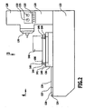
- the in the Fig. 2 to 4 shown workpiece processing device 120 comprises a substantially cuboidal base body 122, on the upper side 124 of a guide device 126 and arranged next to the guide device 126 tower-shaped tool carrier device 128 are arranged.
- the tool carrier device 128 is substantially parallelepiped-shaped and has, on its side facing the guide device 126, a machining tool, for example a milling and / or drilling device 130, and on one side adjacent thereto a measuring device 132 in this embodiment as a pressure measuring device with two as clamping pressure indicators trained ads 133 on.
- the guide device 126 has two mutually parallel, spaced apart guide rails 134.
- a pallet 136 is arranged, which has on its underside to the guide rails 134 complementary guide grooves 138. The pallet 136 is thus guided guided along the guide rails 134.
- the guide rails 134 are arranged so that the pallet 136 is movable toward or away from the milling and / or drilling device 130.
- the position of the pallet 136 on the end of the guide rails 134 facing the milling and / or boring device 130 is referred to below as the "workpiece machining position”.
- the milling and / or boring device 130 opposite part of the workpiece processing device 120 is formed as a changeover table 137.
- the "workpiece change position" is in this embodiment, the position of the pallet 136 at the milling and / or drilling device 130 remote from the end of the guide rails 134, that is, on the shuttle table 137th
- the pallet 136 is mechanically movable by means of a movement device (not shown).
- the workpiece receiving device 140 comprises a bearing surface 141 arranged on its upper side.
- the bearing surface 141 has a multiplicity of blind holes 142 arranged in a grid-shaped pattern for receiving fastening means of one or more clamping devices 144.
- the tensioning devices 144 are designed as tensioning elements 146, which can be fixed relative to the blind holes 142.
- a workpiece 148 can be clamped by means of a plurality of clamping elements 146 between the bearing surface 141 of the tool receiving device 140 and the workpiece 148 overarching clamping parts 150 of the clamping elements 146.
- a detection aid 149 is arranged on the workpiece 148.
- the detection aid 149 is designed, for example, as a cross-shaped marking.
- the measuring device 132 arranged on the tower-shaped device 128 has a connection (not shown in the drawings) to a plurality of sensors (also not shown in the drawings) which are arranged in the workpiece receiving device 140 and measure the clamping pressure which is generated by means of the clamping elements 146 the workpiece 148 is exerted.
- the displays 133 of the measuring device 132 indicate this clamping pressure.
- a set-up station 152 is arranged at the distance from the workpiece processing device 120.
- the set-up station 152 comprises an essentially cuboid base body 154 with a guide device 158 mounted on the upper side 156 thereof.
- the guide device 158 comprises two mutually parallel, spaced apart guide rails 160. These guide rails 160 are formed corresponding to the guide rails 134, so that the pallet 136 is guided with the guide grooves 138 guided both on the guide rails 134 and on the guide rails 160.
- the "setup position" in this embodiment is the position of a pallet 136 in which the pallet 136 is located when placed at the set-up station 152.
- a connection between the guide rails 134 and the guide rails 160 is provided such that a pallet 136 can be moved directly from the set-up position into the workpiece machining position and back. Removing the pallet 136 from the guide rails 160 of the set-up station 152 and placing the pallet 136 on the guide rails 134 of the workpiece processing device 120 is not necessary in such an embodiment.
- the first camera 101 is arranged vertically above the tool processing device 120, and its optical axis extends in a vertical plane, so that the first camera detects a workpiece processing region 162.
- the workpiece processing area 162 comprises the pallet 136 in the workpiece processing position with the workpiece holder 140 arranged on the pallet 136, the clamping elements 146 arranged on the workpiece holder 140 and the workpiece 148 clamped by the clamping elements 146. Furthermore, the workpiece processing area 162 comprises the milling and / or drilling device 130th
- the second camera 102 also detects the workpiece processing area 162 detected by the first camera 101.
- the second camera 102 is not arranged vertically above the workpiece processing area 162, but oriented so that its optical axis with respect to the first camera 101 is about 30 ° about a central axis 164, which runs centrally between the guide rails 134 and parallel to the same, is rotated.
- the illumination device 111 comprises a laser device for projection of a stripe pattern and is aligned such that the stripe pattern can be projected onto the objects arranged in the workpiece processing region 162.
- the third camera 103 is disposed vertically above the central axis 164 extending between the guide rails 134, and the optical axis of the third camera 103 extends in a vertical plane containing the central axis 164 and is rotated about 20 ° from the vertical.
- the third camera 103 starting from the position of the first camera 101, is arranged at a distance from the milling and / or drilling device along the central axis 164, so that the third camera 103 has an end remote from the milling and / or drilling device 130 the guide rails 134 on the shuttle table 137 arranged workpiece change region 166 detected.
- the fourth camera 104 is arranged vertically above a central axis 168 extending centrally between the guide rails 160 of the set-up station 152 and parallel thereto. Its optical axis extends in a vertical plane containing the central axis 168 and is rotated about 60 ° with respect to the vertical.
- the fourth camera 104 is offset from the setup station 152 along the central axis 168 so as to engage a pallet 136 disposed in the setup position, including the workpiece receiver 120 disposed on the pallet 136, the clamp members 146 disposed on the workpiece receiver, and the clamp member 146 the workpiece receiving device 120 clamped workpiece 148 detected.
- the area detected by the fourth camera 104 is the setup area 170.
- the fifth camera 105 is arranged at a distance from the displays 133 of the measuring device 132 arranged on the tool carrier device 128 such that their optical axis runs in a horizontal plane and substantially perpendicular to the displays 133, such that a region detected by the fifth camera 105 the two displays 133 of the measuring device 132 comprises.
- the pallet storage device 172 is formed as a shelf-like device with a plurality of, for example eight, storage surfaces 174, wherein each two storage surfaces 174 side by side and four storage surfaces 174 are arranged one above the other. All storage surfaces 174 are slightly larger than a pallet 136 in terms of their horizontal extent.
- the storage surfaces 174 have the guide device 126 of the workpiece processing device 120 and the guide device 158 of the set-up station 152 corresponding guide means 176 for placing a pallet 136.
- the guide means 176 thus each comprise two mutually parallel and spaced guide rails 178th
- a pallet 136 is arranged in a "storage position" when it is arranged on the guide rails 178 of the storage area 174 of the pallet storage device 172 arranged on the upper right with respect to a front side 184 of the pallet storage device 172.
- the sixth camera 106 is disposed vertically above a center horizontal axis 180 extending centrally between the guide rails 178 of the tray 174 of the pallet stocker 172 on the upper right, and the optical axis thereof extends in a vertical plane containing the central axis 180 , and is rotated about 60 ° with respect to the vertical.
- the sixth camera 106 is offset from the storage position along the central axis 180 such that it detects a pallet 136 arranged in the storage position.
- the area covered by the sixth camera 106 is the storage area 182.
- the sixth camera 106 is movable such that each tray surface 174 of the pallet storage device 172 can be detected by moving the sixth camera 106.
- the monitoring device 100, the machine control device 118, the workpiece processing device 120, the set-up station 152 and the pallet storage device 172 form components of a workpiece processing system designated as a whole by 186.
- the monitoring device 100 in particular makes possible the following monitoring operations during the mentioned method steps:
- the sixth camera 106 monitors what kind pallet 136 and workpiece receiving device 140 is in the storage area 182 which it detects. In this way, for example, damaged pallets 136 or pallets 136 of the wrong type can be detected in good time.
- workpiece change region 166 can be monitored whether a workpiece 148 of the desired type is clamped in the desired position and orientation on the workpiece receiving device 140.
- the fifth camera 105 By means of the fifth camera 105, after the workpiece 148 has been clamped on the workpiece receiving device 140, it can be monitored whether the clamping pressure determined by the measuring device 132 and displayed on the display 133 of the measuring device 132, which is exerted on the workpiece 148 by the clamping elements 146, is a default equivalent.
- the clamping elements 146 and the workpiece 148 along the guide device 126 in the workpiece processing position in the detected by the first camera 101 and the second camera 102 and illuminated by the illumination device 111 workpiece processing area 162 is by means of the first camera 101 and the second camera 102 to monitor whether the clamped on the workpiece receiving device 140 workpiece 148 in terms of its nature, its position and its orientation corresponds to a specification.
- the clamping elements 146 and the machined workpiece 148 along the guide 126 from the workpiece processing area 162 to the workpiece change position in the workpiece changing area 166 detected by the third camera 103 releasing the clamping elements 146 and removing the processed one Workpiece 148 of the arranged in the workpiece changing portion 166 workpiece holder 140 is monitored by the third camera 103, whether the pallet 136, the workpiece receiving device 140 and / or the clamping elements 146 were damaged during the machining operation by means of the milling and / or drilling device 130.
- the monitoring of the mentioned process parameters is carried out by an evaluation of the images generated by said cameras in the respective associated image evaluation device 114 and 116, respectively.
- a first type of evaluation which is applicable when a specific area of the workpiece processing system 186 is simultaneously detected by at least two of the cameras 101, 102, 103, 104, 105 and 106, is based on the triangulation principle:
- the first camera 101 and the second camera 102 produce images of the pallet 136 illuminated by the illumination device 111, arranged in the workpiece processing region 162 of the workpiece processing device 120, together with the workpiece holder 140, the clamping elements 146 and the workpiece 148.
- the data containing the image information is transmitted to the common image evaluation device 114. Since the first camera 101 and the second camera 102 detect the workpiece processing area 162 from different angles, the images of the striped pattern projected by the first camera 101 and the second camera 102 on the striped pattern projected by the illumination device 111 are different on the objects arranged in the workpiece processing area 162.
- the image evaluation device 114 Based on these differences, the image evaluation device 114 generates from the image information of the images generated by the first camera 101 and the second camera 102 a three-dimensional model of the pallet 136 arranged in the work processing area 162, including the work receiving device 140, the chucking elements 146, and the work 148 The obtained three-dimensional model is then compared either with a three-dimensional model of a reference real pattern part or with a three-dimensional CAD model. Depending on the predetermined tolerance values, a judgment is then made as to whether the monitored pallet 136, the workpiece receiving device 140, the clamping elements 146 and the workpiece 148 correspond to the specification.
- a further type of evaluation which is also applicable if a specific area of the workpiece processing system 186 is detected only by one of the cameras 101, 102, 103, 104, 105 and 106, is based on a direct comparison of actual images with reference images:
- the monitoring performed by means of the third camera 103, the fourth camera 104 and the sixth camera 106 is based on the comparison of two-dimensional actual images generated by the third camera 103, the fourth camera 104 and the sixth camera 106 with the third camera 103, the fourth Camera 104 and the sixth camera 106 generated by a serving as a reference sample part two-dimensional target images.
- the monitoring performed by means of the fifth camera 105 is based on the comparison of a two-dimensional actual image of the displays 133 of the measuring device 132 generated by the fifth camera 105 with a two-dimensional target image generated by the displays 133 of the measuring device 132 by means of the fifth camera 105, wherein during production of the two-dimensional target image, a workpiece 148 serving as a pattern part is clamped on a workpiece receiving device 140 by means of the clamping elements 146 such that the displays 133 of the measuring device 132 indicate a clamping pressure corresponding to a specification.
- the target images are stored after their generation in an image evaluation device serving for their evaluation, namely in the common image evaluation device 114 or the image evaluation device 116 assigned to the sixth camera 106.
- the evaluation takes place either, as in the case of the images generated by the sixth camera 106, by means of the image evaluation device 116 arranged in the housing of the sixth camera 106 or, as in the case of the third camera 103 , the fourth camera 104, and the fifth camera 105, after the transmission of the image information-containing data by means of the connection cables 112 to the common image evaluation device 114 by the common image evaluation device 114.
- Deviations of the actual images from the corresponding target images are determined, for example, by forming differences between brightness values of mutually corresponding positions in the actual image and in the target image and checking whether these differences exceed a predetermined tolerance value.
- the machine control device 118 then forwards a signal to the workpiece processing device 120, which releases the workpiece processing device 120 for machining a workpiece 148, in the case of the determination of the proper state.
- Examples of the states of the workpiece processing system 186 to be determined by means of the monitoring device 100 are the Fig. 6a to 15b refer to.
- Fig. 6a and 7a the target position of a pallet 136 with the workpiece receiving device 140, the clamping elements 146 and the workpiece 148 is shown.
- the first camera 101 and the second camera 102 By means of the first camera 101 and the second camera 102, a deviation in the position of the pallet 136 from its desired position can be determined. So is in the Fig. 6b and 7b the pallet 136 is located too far away from the milling and / or boring device 130.
- the Fig. 8a and 9a show target images of a workpiece to be machined 148th This is clearly distinguishable in the Fig. 8b and 9b illustrated workpiece 148 ', which has a different outer contour.
- the monitoring device 100 it is possible to determine whether the workpiece 148 intended for machining on the workpiece processing device 120 corresponds to the predetermined type.
- Fig. 10a and 11a is a correctly oriented workpiece shown. If the workpiece, however, as in the Fig. 10b and 11b shown, rotated 180 ° about a vertical axis clamped on the workpiece receiving device 140, so by means of the monitoring device 100 deviates from the default outer contour can be determined.
- the Fig. 12a and 13a 12 shows a pallet 136, a workpiece holder 140, four clamping members 146, and a workpiece 148, which are properly arranged in the workpiece processing position in the workpiece processing area 162, respectively.
- the in the Fig. 12b and 13b The illustrated deviation that no workpiece 148 is clamped on the workpiece receiving device 140 can be determined by means of the monitoring device 100.
- FIG. 14a four of a preset corresponding arranged clamping elements 146 are shown, wherein the above the workpiece 148 extending portions 150 of the clamping elements 146 are each arranged perpendicular to the encompassed by the respective clamping element 146 edge region of the workpiece 148.
- a deviating orientation of the partial regions 150 of the clamping elements 146 is Fig. 14b refer to.
- Figs. 15a and 15b the monitored by the fifth camera 105 displays 133 of the measuring device 132 are shown.
- Fig. 15a indicate the display 133 of the measuring device 132 to a proper clamping pressure, which is exerted by means of the clamping elements 146 on a clamped on the workpiece receiving device 140 workpiece 148. This deviates from the displayed on the displays 133 of the measuring device 132 clamping pressure in Fig. 15b from. It can be monitored by means of the monitoring device 100 whether the clamping pressure displayed on the displays 133 of the measuring device 132 corresponds to a specification.
- a monitoring of a portion of the workpiece processing system 186 takes place with only one camera.
- the workpiece processing region 162 of the workpiece processing device 120 is detected in a side view as it in the Fig. 6a, 6b . 8a, 8b . 10a, 10b . 12a and 12b is shown.
- the position, the type and / or the orientation of the workpiece 148 to be machined and / or the workpiece 148 exerted on the workpiece 148 by means of the clamping elements 146 Clamping pressure can be determined.
- An alternative embodiment of the invention provides for the arrangement of only one camera in such a way that it detects the workpiece processing region 162 of the workpiece processing device 120 in a plan view as it is in the Fig. 7a, 7b . 9a, 9b . 11a, 11b . 13a, 13b . 14a and 14b is shown.
- the position, the type and / or the orientation of the workpiece 148 to be machined and / or the orientation of the clamping parts 150 of the clamping elements 146 can already be determined.
- Monitoring of the workpiece processing system 186 by means of a monitoring device 100 is simpler, more flexible and less expensive compared to monitoring by means of electronic sensors.
Abstract
Description
Die vorliegende Erfindung betrifft eine Werkstückbearbeitungsanlage, umfassend
mindestens eine Überwachungsvorrichtung zur Überwachung der Orientierung mindestens einer Spannvorrichtung zum Einspannen mindestens eines Werkstücks an mindestens einer Werkstückaufnahmevorrichtung und
mindestens eine Spannvorrichtung zum Einspannen mindestens eines Werkstücks an mindestens einer Werkstückaufnahmevorrichtung.The present invention relates to a workpiece processing system comprising
at least one monitoring device for monitoring the orientation of at least one clamping device for clamping at least one workpiece on at least one workpiece receiving device and
at least one clamping device for clamping at least one workpiece on at least one workpiece receiving device.
Solche Werkstückbearbeitungsanlagen mit Überwachungsvorrichtungen, insbesondere zur Automatisierung in der Werkstückspanntechnik, sind aus dem Stand der Technik bekannt.Such workpiece machining systems with monitoring devices, in particular for automation in the workpiece clamping technology, are known from the prior art.
Die Überwachung erfolgt bei den bekannten Überwachungsvorrichtungen mittels Sperrluft oder elektronischer Sensoren, wobei eine umfangreiche Überwachung komplexer Systeme stets eine Vielzahl von Sensoren erfordert, die für jeden Betriebsmodus des zu überwachenden Systems aufwendig justiert werden müssen.The monitoring takes place in the known monitoring devices by means of sealing air or electronic sensors, with extensive monitoring of complex systems always requires a large number of sensors that need to be adjusted consuming for each operating mode of the system to be monitored.
Die
Die
Die
Der vorliegenden Erfindung liegt die Aufgabe zugrunde, eine Werkstückbearbeitungsanlage der eingangs genannten Art zu schaffen, bei welcher auf besonders flexible Art und Weise mittels der Überwachungsvorrichtung eine umfassende Überwachung möglich ist.The present invention has for its object to provide a workpiece machining system of the type mentioned, in which in a particularly flexible manner by means of the monitoring device comprehensive monitoring is possible.
Diese Aufgabe wird bei der eingangs genannten Werkstückbearbeitungsanlage erfindungsgemäß durch die Merkmale von Anspruch 1 gelöst.This object is achieved according to the invention in the aforementioned workpiece machining system by the features of claim 1.
Die erfindungsgemäße Lösung bietet den Vorteil, dass eine Umstellung einer Anlage, welche beispielsweise eine Werkstückbearbeitungsvorrichtung umfasst, auf einen anderen Betriebsmodus, in dem beispielsweise eine neue Art von Werkstücken an der Werkstückbearbeitungsvorrichtung bearbeitet wird, besonders einfach durchführbar ist.The solution according to the invention has the advantage that a changeover of a system, which comprises, for example, a workpiece processing device, to a different operating mode in which, for example, a new type of workpieces is processed on the workpiece processing device, is particularly easy to carry out.
Nach einer Weiterbildung der Erfindung ist eine Verbindung der Überwachungsvorrichtung mit einer die zu überwachenden Objekte bearbeitenden oder umfassenden Werkstückbearbeitungsvorrichtung vorgesehen. Damit kann auf die Werkstückbearbeitungsvorrichtung, in Abhängigkeit von einer mittels mindestens einer Auswertungsvorrichtung durchgeführten Auswertung, automatisch Einfluss genommen werden. Insbesondere kann die Werkstückbearbeitungsvorrichtung in Abhängigkeit von einem Ausgangssignal der Auswertungsvorrichtung von einer Maschinensteuerungsvorrichtung angesteuert werden.According to a development of the invention, a connection of the monitoring device with a workpiece processing device which processes or covers the objects to be monitored is provided. In this way, the workpiece processing device can automatically be influenced as a function of an evaluation performed by means of at least one evaluation device. In particular, the workpiece processing device can be controlled in dependence on an output signal of the evaluation device by a machine control device.
Mittels der Überwachungsvorrichtung sind Objekte ferner vorzugsweise hinsichtlich ihrer Art und/oder ihrer Position überwachbar.Furthermore, by means of the monitoring device, objects can preferably be monitored with regard to their type and / or their position.
Unter einer "Überwachung der Art" (Identifikation) ist in dieser Beschreibung und in den beigefügten Ansprüchen zu verstehen, dass unterschiedliche Gruppen von überwachten Objekten mittels der Überwachungsvorrichtung unterscheidbar sind. Insbesondere ist ermittelbar, ob der Typ des beispielsweise an der Werkstückaufnahmevorrichtung gehaltenen Werkstücks demjenigen entspricht, welcher zur Bearbeitung mittels der Werkstückbearbeitungsvorrichtung vorgesehen ist.By "type-of-surveillance" (identification) is meant, in this specification and in the appended claims, that different groups of monitored objects are distinguishable by means of the monitoring device. In particular, it can be determined whether the type of the workpiece held, for example, on the workpiece receiving device corresponds to that which is provided for processing by means of the workpiece processing device.
Unter einer "Überwachung der Position" ist in dieser Beschreibung und in den beigefügten Ansprüchen zu verstehen, dass die Abweichung einer Istposition eines überwachten Objekts von seiner Sollposition, insbesondere von der in einem Sollbild oder in einem CAD-Modell vorgegebenen Sollposition, ermittelbar ist.A "monitoring of the position" in this description and in the attached claims means that the deviation of an actual position of a monitored object from its desired position, in particular from the predetermined position in a target image or in a CAD model, can be determined.
Eine "Istposition" ist dabei die Position, in der sich ein Objekt zum Zeitpunkt einer Erzeugung eines Bildes dieses Objekts befindet, das heißt, dass der Begriff "Istposition" die mittels einer Bilderzeugungsvorrichtung in einem Bild festgehaltene Position eines Objekts bezeichnet.In this case, an "actual position" is the position in which an object is located at the time of generation of an image of this object, that is to say that the term "actual position" designates the position of an object recorded in an image by means of an image generation device.
Der Begriff "Sollposition" bezieht sich dagegen auf die gewünschte Position des Objekts, in der es sich im jeweiligen Fall befinden soll. Insbesondere ist unter einer "Sollposition" eine Referenzposition zu verstehen, das heißt eine Position, in der ein als Referenz definiertes Objekt bei ordnungsgemäßer Durchführung vordefinierter Schritte aufzufinden sein soll.By contrast, the term "target position" refers to the desired position of the object in which it should be located in the respective case. In particular, a "target position" is to be understood as meaning a reference position, that is to say a position in which an object defined as a reference is to be found when properly performing predefined steps.
Eine mittels mindestens einer Bildauswertungsvorrichtung durchgeführte Auswertung erfolgt vorzugsweise unter Verwendung mindestens eines Toleranzwertes, wobei innerhalb des vorgegebenen mindestens einen Toleranzwerts eine Abweichung der Istposition des überwachten Objekts von seiner Sollposition noch immer als Übereinstimmung der Istposition mit der Sollposition gewertet werden kann. Derartige Toleranzwerte tragen der Tatsache Rechnung, dass in realen Systemen oft detektierbare Abweichungen auftreten. Da es wünschenswert sein kann, kleinere Abweichungen zu tolerieren, stellt die Verwendung eines Toleranzwertes ein adäquates Mittel zur Vermeidung zu hoher Prozessabbruchquoten unter gleichzeitiger Einhaltung der gewünschten Qualitätskriterien dar.An evaluation carried out by means of at least one image evaluation device is preferably carried out using at least one tolerance value, wherein a deviation of the actual position of the monitored object from its desired position within the predetermined at least one tolerance value can still be evaluated as a match of the actual position with the desired position. Such tolerance values take account of the fact that deviations that are often detectable occur in real systems. Since it may be desirable to tolerate minor deviations, the use of a tolerance value is an adequate means for avoiding too high process termination rates while maintaining the desired quality criteria.
Nach einer Weiterbildung der Erfindung ist vorgesehen, dass die Absolutkoordinaten mindestens eines überwachten Objekts bezüglich eines vorgegebenen Koordinatensystems ermittelbar sind.According to a development of the invention, it is provided that the absolute coordinates of at least one monitored object with respect to a predetermined coordinate system can be determined.
Besonders vorteilhaft ist die Ermittlung von Absolutkoordinaten bei der Verwendung einer Vielzahl von Bilderzeugungsvorrichtungen, da dann die Position jedes von mindestens einer Bilderzeugungsvorrichtung erfassten Objekts relativ zu der gesamten Anlage ermittelbar ist.Particularly advantageous is the determination of absolute coordinates in the use of a plurality of image forming devices, since then the position of each detected by at least one image forming device object is determined relative to the entire system.
Unter einer "Überwachung der Orientierung" ist in dieser Beschreibung und in den beigefügten Ansprüchen die Überwachung der räumlichen Ausrichtung des überwachten Objekts, insbesondere bezüglich einer Drehachse, zu verstehen.By "monitoring the orientation" is meant in this description and in the appended claims the monitoring of the spatial orientation of the monitored object, in particular with respect to a rotation axis.
Vorzugsweise ist mittels der Überwachungsvorrichtung folglich ermittelbar, ob ein überwachtes Objekt bezüglich seiner Sollausrichtung gedreht, insbesondere um 180° um eine vertikale Achse gedreht, angeordnet ist.By means of the monitoring device, it is therefore preferably possible to determine whether a monitored object is rotated with respect to its target orientation, in particular rotated through 180 ° about a vertical axis.
Bei einer bevorzugten Ausgestaltung der Erfindung sind die Merkmale Art, Position und Orientierung eines überwachten Objekts nicht nur zusammen, sondern auch einzeln, insbesondere jedoch in beliebiger Kombination miteinander, überwachbar.In a preferred embodiment of the invention, the features type, position and orientation of a monitored object not only together, but also individually, but in particular in any combination with each other, monitored.
Vorzugsweise sind ferner unterschiedliche Objekte, insbesondere gleichzeitig, bezüglich unterschiedlicher Merkmale überwachbar. Beispielsweise kann vorgesehen sein, eine Werkstückaufnahmevorrichtung auf deren Position und gleichzeitig ein an der Werkstückaufnahmevorrichtung angeordnetes Werkstück auf dessen Art und/oder dessen Orientierung zu überwachen.Furthermore, different objects, in particular simultaneously, can be monitored with respect to different features. For example, it may be provided to monitor a workpiece receiving device at its position and at the same time a workpiece arranged on the workpiece receiving device in its type and / or orientation.
Einerseits ist es günstig, wenn mindestens eine Bilderzeugungsvorrichtung unbeweglich ausgebildet ist. Dies hat den Vorteil einer besonders einfachen Montage.On the one hand, it is favorable if at least one image-forming device is immovable. This has the advantage of a particularly simple installation.
Andererseits kann es vorteilhaft sein, wenn mindestens eine Bilderzeugungsvorrichtung beweglich, insbesondere an einer Führungseinrichtung geführt verfahrbar, ausgebildet ist. Auf diese Art und Weise ist ein bewegtes Objekt fortlaufend überwachbar.On the other hand, it can be advantageous if at least one image-forming device is designed to be movable, in particular movably guided on a guide device. In this way, a moving object is continuously monitored.
Eine vorteilhafte Ausgestaltung der Erfindung sieht vor, dass mindestens eine Bilderzeugungsvorrichtung mindestens ein abbildendes optisches System, insbesondere ein Objektiv, und mindestens einen Bildwandler, insbesondere einen CCD-Chip, umfasst.An advantageous embodiment of the invention provides that at least one imaging device comprises at least one imaging optical system, in particular a lens, and at least one image converter, in particular a CCD chip.
Um die Lichtverhältnisse für die Bilderzeugung zu verbessern, weist die Überwachungsvorrichtung vorzugsweise mindestens eine Beleuchtungsvorrichtung auf.In order to improve the light conditions for the image formation, the monitoring device preferably has at least one illumination device.
Eine vorteilhafte Ausgestaltung der Erfindung sieht vor, dass mindestens eine Beleuchtungsvorrichtung mindestens einen Laser umfasst.An advantageous embodiment of the invention provides that at least one illumination device comprises at least one laser.
Alternativ oder ergänzend hierzu kann vorgesehen sein, dass mindestens eine Beleuchtungsvorrichtung mindestens eine Beleuchtungseinheit aufweist, die mindestens eine Leuchtdiode umfasst.Alternatively or additionally, it can be provided that at least one illumination device has at least one illumination unit which comprises at least one light-emitting diode.
Insbesondere zur Identifikation der Objekte ist es besonders vorteilhaft, wenn mittels mindestens einer Beleuchtungseinheit ein Muster, insbesondere ein linienartiges, ein streifenartiges und/oder ein gitterartiges Muster, auf mindestens einen von mindestens einer Bilderzeugungsvorrichtung erfassten Bereich projizierbar ist.In particular for the identification of the objects, it is particularly advantageous if by means of at least one illumination unit a pattern, in particular a line-like, a strip-like and / or a grid-like pattern, can be projected onto at least one area detected by at least one image generation device.
Bei einer vorteilhaften Ausgestaltung umfasst mindestens ein von mindestens einer Bilderzeugungsvorrichtung erfasster Bereich mindestens eine Werkstückaufnahmevorrichtung und vorzugsweise mindestens ein Werkstück, wobei die Werkstückaufnahmevorrichtung und gegebenenfalls auch das mindestens eine Werkstück in einer Werkstückbearbeitungsposition zur Bearbeitung des mindestens einen Werkstücks angeordnet sind. Auf diese Weise ist das Werkstück, wie auch die Werkstückaufnahmevorrichtung, vor, während und nach dem Bearbeitungsvorgang überwachbar.In an advantageous embodiment, at least one area detected by at least one image-forming device comprises at least one workpiece receiving device and preferably at least one workpiece, wherein the workpiece-receiving device and optionally also the at least one workpiece are arranged in a workpiece processing position for processing the at least one workpiece. In this way, the workpiece, as well as the workpiece receiving device, before, during and after the processing operation monitored.
Vorteilhaft ist es, wenn an mindestens einem Werkstück, an mindestens einer Werkstückaufnahmevorrichtung und/oder an mindestens einer Spannvorrichtung mindestens eine Detektionshilfe zur Vereinfachung einer mittels mindestens einer Bildauswertungsvorrichtung durchgeführten Auswertung eines Bildes, welches mittels mindestens einer Bilderzeugungsvorrichtung von dem mindestens einen Werkstück, der mindestens einen Werkstückaufnahmevorrichtung und/oder der mindestens einen Spannvorrichtung erzeugt wird, angeordnet ist.It is advantageous if on at least one workpiece, on at least one workpiece receiving device and / or on at least one clamping device at least one detection aid to simplify a performed by at least one image evaluation device evaluation of an image, which by means of at least one image forming device of the at least one workpiece, the at least one Workpiece receiving device and / or the at least one clamping device is generated is arranged.
Nach einer weiteren vorteilhaften Ausführungsform der Erfindung ist mittels mindestens einer Bilderzeugungsvorrichtung mindestens ein Sollbild erzeugbar, welches mindestens ein Werkstück, mindestens eine Werkstückaufnahmevorrichtung und/oder mindestens eine Spannvorrichtung zeigt. Damit kann auf einfache Art und Weise eine Referenz für die zu überwachenden Objekte festgelegt werden.According to a further advantageous embodiment of the invention, at least one target image can be generated by means of at least one image generating device, which shows at least one workpiece, at least one workpiece receiving device and / or at least one clamping device. In this way, a reference for the objects to be monitored can be defined in a simple manner.
Es hat sich als günstig erwiesen, wenn mindestens ein Sollbild erzeugbar ist, welches ein Werkstück, eine Werkstückaufnahmevorrichtung und eine Spannvorrichtung, umfassend mehrere, beispielsweise vier, Spannelemente, zeigt.It has proven to be advantageous if at least one target image can be generated, which shows a workpiece, a workpiece receiving device and a clamping device comprising a plurality of, for example four, clamping elements.
Vorteilhaft ist es ferner, wenn mindestens ein Sollbild mindestens ein zumindest teilweise abgebildetes Objekt in seiner Sollart, Sollposition und/oder Sollorientierung zeigt, wobei mittels mindestens einer Bildauswertungsvorrichtung eine Bildauswertung durchführbar ist, bei der mindestens ein Sollbild mit mindestens einem Istbild verglichen wird.It is also advantageous if at least one target image shows at least one at least partially imaged object in its target type, target position and / or target orientation, whereby image evaluation can be carried out by means of at least one image evaluation device in which at least one target image is compared with at least one actual image.
Nach einer Weiterbildung der Erfindung kann vorgesehen sein, dass mindestens eine mittels mindestens einer Bildauswertungsvorrichtung durchgeführte Bildauswertung auf einem Vergleich der Kontrast- und/oder Helligkeitswerte des mindestens einen Istbildes mit denjenigen des entsprechenden Sollbildes beruht.According to a development of the invention, it can be provided that at least one image evaluation performed by means of at least one image evaluation device is based on a comparison of the contrast and / or brightness values of the at least one actual image with those of the corresponding target image.
Vorzugsweise ist eine Abweichung der Istposition mindestens eines Teils der Werkstückbearbeitungsvorrichtung von der entsprechenden Sollposition bereits dann detektierbar, wenn dieser mindestens eine Teil von mindestens einer Bilderzeugungsvorrichtung zumindest teilweise erfasst wird.Preferably, a deviation of the actual position of at least one part of the workpiece processing device from the corresponding setpoint position can already be detected if this at least one part of at least one image generation device is at least partially detected.
Bei einer Ausführungsform der Erfindung kann vorgesehen sein, dass mittels mindestens einer Messvorrichtung eine Größe ermittelbar ist, von der die durch mindestens eine Spannvorrichtung auf mindestens ein Werkstück ausgeübte Spannkraft abhängt.In one embodiment of the invention it can be provided that a size can be determined by means of at least one measuring device, from which the clamping force exerted by at least one clamping device on at least one workpiece depends.
Die mittels mindestens einer Messvorrichtung ermittelbare Größe kann beispielsweise der durch mindestens eine Spannvorrichtung auf mindestens ein Werkstück ausgeübte Spanndruck sein.The variable which can be determined by means of at least one measuring device can be, for example, the clamping pressure exerted by at least one clamping device on at least one workpiece.
Die mittels mindestens einer Messvorrichtung ermittelbare Größe kann aber auch eine elektrische Größe, insbesondere ein elektrischer Strom, sein. Beispielsweise in der Magnetspanntechnik kann so ermittelt werden, wie groß die mittels mindestens einer magnetischen Spannvorrichtung auf mindestens ein Werkstück ausgeübte Spannkraft ist.However, the variable which can be determined by means of at least one measuring device can also be an electrical variable, in particular an electric current. For example, in the magnetic clamping technique, it can be determined how large the clamping force exerted by at least one magnetic clamping device on at least one workpiece.
Einerseits kann vorgesehen sein, dass eine Messvorrichtung mit der Überwachungsvorrichtung verbunden ist, um so direkt Signale von der Messvorrichtung zur Überwachungsvorrichtung zu übermitteln.On the one hand, it can be provided that a measuring device is connected to the monitoring device, so as to transmit signals directly from the measuring device to the monitoring device.
Andererseits kann es von Vorteil sein, wenn mindestens eine Bilderzeugungsvorrichtung der Überwachungsvorrichtung mindestens eine Anzeige einer Messvorrichtung erfasst. Dies ist insbesondere dann eine bevorzugte Ausgestaltung der Erfindung, wenn eine Überwachungsvorrichtung an einer die Messvorrichtung umfassenden Werkstückbearbeitungsvorrichtung angeordnet ist, welche keine Schnittstelle zur Datenübertragung von der Messvorrichtung zu der Überwachungsvorrichtung aufweist.On the other hand, it can be advantageous if at least one image generating device of the monitoring device detects at least one display of a measuring device. This is a preferred embodiment of the invention, in particular, when a monitoring device is arranged on a workpiece processing device comprising the measuring device, which has no interface for data transmission from the measuring device to the monitoring device.
Bei einer Ausführungsform der Erfindung kann vorgesehen sein, dass die Überwachungsvorrichtung mindestens eine Schnittstelle zur Übertragung von Signalen zu mindestens einer Maschinensteuerungsvorrichtung umfasst.In an embodiment of the invention, it may be provided that the monitoring device comprises at least one interface for transmitting signals to at least one machine control device.
Nach einer vorteilhaften Ausführungsform der Erfindung kann vorgesehen sein, dass mittels mindestens einer Schnittstelle von der mindestens einen Messvorrichtung mindestens ein Signal an mindestens eine Auswertungsvorrichtung und/oder mindestens ein Signal an mindestens eine Maschinensteuerungsvorrichtung übertragbar ist, wobei, basierend auf dem mindestens einen Signal, mindestens eine Funktion der Werkstückbearbeitungsvorrichtung freischaltbar oder sperrbar ist.According to an advantageous embodiment of the invention can be provided that at least one signal to at least one evaluation device and / or at least one signal to at least one machine control device is transferable by at least one interface of the at least one measuring device, based on the at least one signal, at least a function of the workpiece processing device is unlockable or lockable.
Ferner kann bei einer Ausgestaltung der Erfindung vorgesehen sein, dass von mindestens einer Bildauswertungsvorrichtung über mindestens eine Schnittstelle mindestens ein Signal an mindestens eine Maschinensteuerungsvorrichtung übertragbar ist, wobei, basierend auf dem mindestens einen Signal, mindestens eine Funktion der Werkstückbearbeitungsvorrichtung freischaltbar oder sperrbar ist.Furthermore, in an embodiment of the invention, at least one signal can be transmitted from at least one image evaluation device to at least one machine control device, wherein at least one function of the workpiece machining device can be unlocked or blocked based on the at least one signal.
Vorteilhaft ist es, wenn eine freischaltbare Funktion die Bearbeitung des Werkstücks ist.It is advantageous if an unlockable function is the machining of the workpiece.
Ferner kann es vorteilhaft sein, wenn die freischaltbare Funktion die Zuführung mindestens einer mindestens ein Werkstück aufnehmenden Werkstückaufnahmevorrichtung zu der Werkstückbearbeitungsvorrichtung ist.Furthermore, it may be advantageous if the unlockable function is the supply of at least one at least one workpiece receiving workpiece receiving device to the workpiece processing device.
Werden von mehreren Bilderzeugungsvorrichtungen mehrere Bilder von einem oder mehreren zu überwachenden Objekten im wesentlichen gleichzeitig erzeugt, so erfolgt die Freischaltung einer Funktion der Werkstückbearbeitungsvorrichtung vorzugsweise erst nach der Auswertung aller im wesentlichen gleichzeitig erzeugten Bilder.If a plurality of images of one or more objects to be monitored are generated substantially simultaneously by a plurality of image generation devices, the activation of a function of the workpiece processing device preferably takes place only after the evaluation of all images generated substantially simultaneously.
Vorzugsweise umfasst die Überwachungsvorrichtung mindestens zwei Bilderzeugungsvorrichtungen, wobei mittels mindestens zweier Bilderzeugungsvorrichtungen im wesentlichen gleichzeitig Bilder erzeugbar sind.Preferably, the monitoring device comprises at least two image-forming devices, wherein images can be generated substantially simultaneously by means of at least two image-forming devices.
Eine bevorzugte Ausführungsform der Erfindung sieht vor, dass mittels mindestens einer Bildauswertungsvorrichtung eine auf dem Triangulationsprinzip beruhende Bildauswertung durchführbar ist, wobei mindestens zwei Bilderzeugungsvorrichtungen aus unterschiedlichen Blickwinkeln zwei einander überschneidende Bereiche erfassen, die mindestens ein Werkstück, mindestens eine Werkstückaufnahmevorrichtung und/oder mindestens eine Spannvorrichtung mit mindestens einem mittels mindestens einer Beleuchtungsvorrichtung darauf projizierten Muster umfassen, wobei aus den erzeugten Bildern mittels mindestens einer Bildauswertungsvorrichtung ein Modell generiert wird, welches die dreidimensionale Struktur der erfassten Bereiche, einschließlich des mindestens einen Werkstücks, der mindestens einen Werkstückaufnahmevorrichtung und/oder der mindestens einen Spannvorrichtung, wiedergibt, und wobei das so generierte dreidimensionale Istmodell zur Ermittlung von Abweichungen mit einem dreidimensionalen Sollmodell verglichen wird.A preferred embodiment of the invention provides that an image evaluation based on the principle of triangulation can be carried out by means of at least one image evaluation device, wherein at least two imaging devices from two different angles capture two overlapping regions comprising at least one workpiece, at least one workpiece holder and / or at least one clamping device at least one pattern projected thereon by means of at least one illumination device, wherein a model is generated from the generated images by means of at least one image evaluation device, which comprises the three-dimensional structure of the detected regions, including the at least one workpiece, the at least one workpiece receiving device and / or the at least one clamping device , and wherein the thus generated three-dimensional actual model for determining deviations with a dreidimensiona len desired model is compared.
Nach einer vorteilhaften Ausgestaltung der Erfindung kann vorgesehen sein, dass das generierte dreidimensionale Istmodell zur Ermittlung von Abweichungen mit einem dreidimensionalen CAD-Modell verglichen wird.According to an advantageous embodiment of the invention, it can be provided that the generated three-dimensional actual model for determining deviations is compared with a three-dimensional CAD model.
Vorzugsweise benötigen die Bilderzeugung und die Bildauswertung des erzeugten Bildes höchstens eine Sekunde.Preferably, the image generation and the image evaluation of the generated image require at most one second.
Bei einer vorteilhaften Ausgestaltung der Erfindung werden mehrere Bilder vorzugsweise gleichzeitig erzeugt und anschließend vorzugsweise gleichzeitig ausgewertet. Die Gesamtdauer der Bilderzeugung und der Bildauswertung erhöht sich folglich im wesentlichen nicht mit der Anzahl der zu erzeugenden und auszuwertenden Bilder.In an advantageous embodiment of the invention, several images are preferably generated simultaneously and then evaluated preferably simultaneously. Consequently, the total duration of the image generation and the image evaluation essentially does not increase with the number of images to be generated and evaluated.
Nach einer Weiterbildung der Erfindung umfasst mindestens ein von mindestens einer Bilderzeugungsvorrichtung erfasster Bereich mindestens einen Wechseltisch und/oder mindestens einen Rüstplatz zumindest teilweise.According to a development of the invention, at least one area covered by at least one image-generating device comprises at least one shuttle table and / or at least one set-up station at least partially.
Unter einem "Wechseltisch" ist in der Beschreibung und den beigefügten Ansprüchen eine Vorrichtung zu verstehen, welche der Entnahme mindestens eines bereits bearbeiteten Werkstücks von mindestens einer Werkstückaufnahmevorrichtung und der Anordnung mindestens eines unbearbeiteten Werkstücks an mindestens einer Werkstückaufnahmevorrichtung und/oder dem Austausch der gesamten Werkstückaufnahmevorrichtung einschließlich des an der Werkstückaufnahmevorrichtung angeordneten mindestens einen Werkstücks und der gegebenenfalls mindestens einen an der Werkstückaufnahmevorrichtung angeordneten Spannvorrichtung dient.A "shuttle table" in the description and the appended claims is understood to mean a device which includes the removal of at least one already machined workpiece from at least one workpiece receiving device and the arrangement of at least one unprocessed workpiece on at least one workpiece receiving device and / or the replacement of the entire workpiece receiving device the arranged on the workpiece receiving device at least one workpiece and optionally serves at least one arranged on the workpiece receiving device clamping device.
Unter einem "Rüstplatz" ist in der Beschreibung und in den beigefügten Ansprüchen eine Vorrichtung zu verstehen, die der Vorbereitung mindestens einer Werkstückaufnahmevorrichtung zur Aufnahme einer bestimmten Gruppe von Werkstücken dient.A "set-up station" in the description and in the appended claims is understood to mean a device which serves to prepare at least one workpiece receiving device for receiving a specific group of workpieces.
Insbesondere ist ein Rüstplatz eine Vorrichtung, die der Anordnung mindestens einer Spannvorrichtung an mindestens einer Werkstückaufnahmevorrichtung dient, wobei die mindestens eine Spannvorrichtung derart angeordnet wird, dass einzelne Werkstücke einer bestimmten Gruppe von Werkstücken an der Werkstückaufnahmevorrichtung eingespannt und nach einer Bearbeitung des Werkstücks mittels der Werkstückbearbeitungsvorrichtung von der Werkstückaufnahmevorrichtung entfernt werden können.In particular, a set-up station is a device which serves to arrange at least one clamping device on at least one workpiece receiving device, wherein the at least one clamping device is arranged such that individual workpieces of a specific group of workpieces are clamped to the workpiece receiving device and after machining of the workpiece by means of the workpiece machining device the workpiece receiving device can be removed.
Vorteilhafterweise kann vorgesehen sein, dass mindestens ein Werkstück, mindestens eine Spannvorrichtung und/oder mindestens eine Werkstückaufnahmevorrichtung an mindestens einem Rüstplatz für die Verwendung in oder an einer Werkstückbearbeitungsvorrichtung vorbereitet, insbesondere umgerüstet, ausgetauscht, gereinigt, zerlegt und/oder zusammengebaut wird.Advantageously, it may be provided that at least one workpiece, at least one clamping device and / or at least one workpiece receiving device is prepared for at least one set-up station for use in or on a workpiece processing device, in particular converted, replaced, cleaned, disassembled and / or assembled.
Bei einer vorteilhaften Ausgestaltung der erfindungsgemäßen Überwachungsvorrichtung ist mindestens eine Bilderzeugungsvorrichtung derart angeordnet, dass vor einem Einbringen der mindestens einen Werkstückaufnahmevorrichtung in einen Bearbeitungsraum, in dem die Werkstückbearbeitungsvorrichtung angeordnet ist, mittels der mindestens einen Bilderzeugungsvorrichtung mindestens ein Bild eines Bereichs erzeugbar ist, welcher das mindestens eine Werkstück, die mindestens eine Werkstückaufnahmevorrichtung und/oder die mindestens eine Spannvorrichtung zumindest teilweise umfasst.In an advantageous embodiment of the monitoring device according to the invention at least one image forming device is arranged such that prior to introduction of the at least one workpiece receiving device in a processing space in which the workpiece processing device is arranged, by means of the at least one image forming device at least one image of an area can be generated, which at least one Workpiece comprising at least one workpiece receiving device and / or the at least one clamping device at least partially.
Besonders vorteilhaft ist es, wenn mindestens eine Bilderzeugungsvorrichtung oberhalb der Werkstückbearbeitungsvorrichtung, insbesondere an einer Deckenwand eines Bearbeitungsraumes, angeordnet ist. Auf diese Weise ist ein besonders großer Bereich mittels der mindestens einen Bilderzeugungsvorrichtung erfassbar.It is particularly advantageous if at least one image-forming device is arranged above the workpiece-processing device, in particular on a ceiling wall of a processing space. In this way, a particularly large area can be detected by means of the at least one image generating device.
Vorzugsweise umfasst mindestens ein von mindestens einer Bilderzeugungsvorrichtung erfasster Bereich eine Palettenlagervorrichtung zumindest teilweise.Preferably, at least one area detected by at least one image generation device comprises at least partially a pallet storage device.
Unter einer "Palettenlagervorrichtung" ist eine Vorrichtung zur Lagerung von Paletten zu verstehen. Insbesondere können an den Paletten Werkstücke und/oder Werkstückaufnahmevorrichtungen, vorzugsweise einschließlich der daran eingespannten Werkstücke, angeordnet sein.A "pallet storage device" is understood to mean a device for storing pallets. In particular, workpieces and / or workpiece receiving devices, preferably including the workpieces clamped thereto, can be arranged on the pallets.
Bei einer vorteilhaften Ausgestaltung der Erfindung ermöglicht die zumindest teilweise Erfassung einer Palettenlagervorrichtung mittels mindestens einer Bilderzeugungsvorrichtung die Überwachung der mittels der Werkstückbearbeitungsvorrichtung zu bearbeitenden Werkstücke, bevor diese der Werkstückbearbeitungsvorrichtung zugeführt werden.In an advantageous embodiment of the invention, the at least partial detection of a pallet storage device by means of at least one image forming device allows monitoring of the workpieces to be machined by the workpiece processing device before these are fed to the workpiece processing device.
Die erfindungsgemäße Werkstückbearbeitungsanlage umfasst neben mindestens einer Überwachungsvorrichtung vorzugsweise
mindestens ein Werkstück, welches mittels mindestens einer Spannvorrichtung an einer Werkstückbearbeitungsvorrichtung oder an mindestens einer Werkstückaufnahmevorrichtung eingespannt ist, und/oder
mindestens eine Werkstückaufnahmevorrichtung, an der das mindestens eine Werkstück gehalten ist.The workpiece machining system according to the invention preferably comprises in addition to at least one monitoring device
at least one workpiece, which is clamped by means of at least one clamping device on a workpiece processing device or on at least one workpiece receiving device, and / or
at least one workpiece receiving device on which the at least one workpiece is held.
Nach einer Weiterbildung der Erfindung kann vorgesehen sein, dass der Werkstückbearbeitungsvorrichtung mindestens ein Wechseltisch und/oder mindestens ein Rüstplatz zugeordnet ist.According to a development of the invention it can be provided that the workpiece processing device is assigned at least one shuttle table and / or at least one set-up station.
Es kann ferner vorteilhaft sein, wenn der Werkstückbearbeitungsvorrichtung mindestens eine Palettenlagervorrichtung zugeordnet ist.It may also be advantageous if the workpiece processing device is associated with at least one pallet storage device.
Besonders vorteilhaft ist es, wenn die Werkstückbearbeitungsanlage mindestens eine Werkstückbearbeitungsvorrichtung, mindestens einen Wechseltisch und/oder mindestens einen Rüstplatz und/oder mindestens eine Palettenlagervorrichtung umfasst.It is particularly advantageous if the workpiece processing system comprises at least one workpiece processing device, at least one shuttle table and / or at least one set-up station and / or at least one pallet storage device.
Eine vorteilhafte Ausführungsform der Erfindung sieht vor, dass mindestens eine Werkstückaufnahmevorrichtung an mindestens einer Führungseinrichtung geführt verfahrbar ausgebildet ist.An advantageous embodiment of the invention provides that at least one workpiece receiving device is guided guided guided on at least one guide means.
Eine besonders bevorzugte Ausgestaltung der Erfindung sieht vor, dass mindestens eine Werkstückaufnahmevorrichtung mittels mindestens einer Führungseinrichtung mindestens zweidimensional verfahrbar, insbesondere dreidimensional verfahrbar, ausgebildet ist.A particularly preferred embodiment of the invention provides that at least one workpiece receiving device is at least two-dimensionally movable, in particular three-dimensionally movable, by means of at least one guide device.
Nach einer weiteren vorteilhaften Ausführungsform der Erfindung ist mindestens eine Werkstückaufnahmevorrichtung mittels mindestens einer als Drehteller ausgebildeten Führungseinrichtung verfahrbar ausgebildet.According to a further advantageous embodiment of the invention, at least one workpiece receiving device is designed to be movable by means of at least one guide device designed as a turntable.
Es ist vorgesehen, dass die mindestens eine Spannvorrichtung mindestens ein Spannelement umfasst, wobei mindestens ein Werkstück zwischen das mindestens eine Spannelement und mindestens eine an der Werkstückaufnahmevorrichtung angeordnete Auflagefläche für das mindestens eine Werkstück spannbar ist.It is provided that the at least one clamping device comprises at least one clamping element, wherein at least one workpiece between the at least one clamping element and at least one bearing surface arranged on the workpiece receiving device for the at least one workpiece can be clamped.
Insbesondere ist vorgesehen, dass mindestens ein Werkstück zwischen mindestens ein das Werkstück übergreifendes Spannteil eines Spannelements der Spannvorrichtung und mindestens eine an der Werkstückaufnahmevorrichtung angeordnete Auflagefläche für das mindestens eine Werkstück spannbar ist und mittels der Überwachungsvorrichtung ermittelbar ist, ob das mindestens eine das Werkstück übergreifende Spannteil des Spannelements der Spannvorrichtung eine einer Vorgabe entsprechende Orientierung aufweist.In particular, it is provided that at least one workpiece can be tensioned between at least one clamping element of a clamping element of the clamping device and at least one support surface arranged on the workpiece receiving device and can be determined by means of the monitoring device, if the at least one clamping part of the workpiece overlaps the workpiece Clamping element of the clamping device has a specification corresponding orientation.
Nach einer vorteilhaften Ausgestaltung der Erfindung weist die mindestens eine Spannvorrichtung mindestens vier Spannelemente zum Einspannen mindestens eines Werkstücks auf.According to an advantageous embodiment of the invention, the at least one clamping device has at least four clamping elements for clamping at least one workpiece.
Die vorliegende Erfindung betrifft ferner ein Verfahren zur Überwachung der Orientierung mindestens einer Spannvorrichtung zum Einspannen mindestens eines Werkstücks an mindestens einer Werkstückaufnahmevorrichtung.The present invention further relates to a method for monitoring the orientation of at least one clamping device for clamping at least one workpiece on at least one workpiece receiving device.
Der vorliegenden Erfindung liegt die Aufgabe zugrunde, ein solches Verfahren zu schaffen, welches auf flexible Art und Weise eine umfassende Überwachung auch komplexer Systeme ermöglicht.The present invention has for its object to provide such a method which allows flexible monitoring of complex systems even in a comprehensive manner.
Diese Aufgabe wird bei dem vorstehend genannten Verfahren erfindungsgemäß durch die Merkmale von Anspruch 11 gelöst.This object is achieved according to the invention by the features of claim 11 in the aforementioned method.
Die Merkmale und Vorteile besonderer Ausgestaltungen des erfindungsgemäßen Verfahrens wurden bereits vorstehend im Zusammenhang mit den besonderen Ausgestaltungen der erfindungsgemäßen Werkstückbearbeitungsanlage erläutert.The features and advantages of particular embodiments of the method according to the invention have already been explained above in connection with the particular embodiments of the workpiece machining system according to the invention.
Die erfindungsgemäße Werkstückbearbeitungsanlage eignet sich Insbesondere zur Durchführung des erfindungsgemäßen Verfahrens.The workpiece machining system according to the invention is particularly suitable for carrying out the method according to the invention.
Die vorliegende Erfindung kann den Vorteil bieten, dass von einem Gesamtsystem, bestehend aus einer Bilderzeugungsvorrichtung, insbesondere einer Kamera, einer Bildauswertungsvorrichtung, insbesondere einer Elektronikeinheit mit Auswertesoftware, sowie einer Schnittstelle, standardisierte Funktionen an jedwede Maschinensteuerung weitergegeben werden können.The present invention can offer the advantage that standardized functions can be passed on to any machine control system from an overall system consisting of an image-forming device, in particular a camera, an image-evaluating device, in particular an electronic unit with evaluation software, as well as an interface.
Vorzugsweise bietet das Gesamtsystem folgende Abfragemöglichkeiten:
- Erkennung, ob eine Maschinenpalette eingefahren ist oder nicht und ob sich diese am korrekten Platz befindet;
- Erkennung des Werkstücks, das heißt Erkennung, ob das richtige Werkstück eingelegt ist oder nicht;
- Erkennung der Lage des Werkstücks, das heißt Erkennung, ob das Werkstück richtig ausgerichtet und/oder in der korrekten Position in der Vorrichtung liegt;
- Erkennung der Anwesenheit des Werkstücks, das heißt Erkennung, ob das Werkstück überhaupt vorhanden ist und/oder ob es exakt an der richtigen Position liegt, so dass die Maschinenfunktion freigegeben werden kann;
- Erkennung der Position der Spannelemente, das heißt Erkennung, ob sich alle Spannelemente in gespanntem Zustand befinden.
- Detecting if a machine pallet has retracted or not and if it is in the correct place;
- Detection of the workpiece, that is, detection of whether or not the correct workpiece is loaded;
- Detecting the position of the workpiece, that is, detecting whether the workpiece is properly aligned and / or in the correct position in the device;
- Detecting the presence of the workpiece, that is, detecting whether the workpiece is even present and / or if it is exactly in the correct position, so that the machine function can be released;
- Detecting the position of the clamping elements, that is, detecting whether all clamping elements are in a tensioned state.
Vorzugsweise können alle im Erkennungsfeld einer Bilderzeugungsvorrichtung befindlichen Parameter mit einem Referenzbild verglichen werden. Nach einer besonders vorteilhaften Ausgestaltung der Erfindung wertet eine Software dabei verschiedene Bereiche des Bildausschnittes aus und bietet ein Signal für jede einzelne Funktion.Preferably, all parameters located in the detection field of an imaging device can be compared with a reference image. According to a particularly advantageous embodiment of the invention, a software evaluates different areas of the image section and provides a signal for each individual function.
Eine Bilderzeugungsvorrichtung ist vorzugsweise an folgenden Positionen angeordnet:
- in einem Maschineninnenraum, vorteilhafterweise an der Decke innen im Maschinenraum, um die gesamte Maschinenpalette inklusive Werkstücke zu erfassen;
- außerhalb eines Bearbeitungsraumes mit Erfassung des Maschineninnenraumes zum Schutz der Bilderzeugungsvorrichtung;
- außerhalb eines Bearbeitungsraumes über einem Wechseltisch, so dass schon vor dem Einschwenken in den Bearbeitungsraum die Erfassung und Überprüfung erfolgen kann;
- komplett außerhalb der Maschine auf einem Rüstplatz;
- komplett außerhalb der Maschine in einer Lagervorrichtung gleich welcher Art.
- in an interior of the machine, advantageously on the ceiling inside the machine room, in order to grasp the entire machine pallet including workpieces;
- outside a processing space with detection of the machine interior to protect the image forming apparatus;
- outside a processing space above a shuttle table, so that even before swiveling into the processing room, the detection and verification can take place;
- completely outside the machine on a set-up station;
- completely outside the machine in a storage device of any kind.
Nach einer vorteilhaften Ausgestaltung der Erfindung kann ein "in Ordnung"-Signal, welches eine Software für jede einzelne Funktion bietet, über eine Schnittstelle an eine Maschinensteuerungsvorrichtung übergeben werden. Die Signale werden in der Maschine in der existierenden Steuerung aufgenommen.According to an advantageous embodiment of the invention, an "OK" signal, which provides software for each individual function, can be transferred via an interface to a machine control device. The signals are recorded in the machine in the existing controller.
Es können dort Abhängigkeiten gebildet werden, wann die Maschine die Freigabe für die Bearbeitung bekommt.Dependencies can be formed there when the machine receives the approval for processing.
Vorzugsweise werden die Merkmale von Bauteilen mit Hilfe einer Beleuchtung durch Laserlinien oder LED-Strahler erkennbar gemacht, um sie anschließend mit Bildbearbeitungssystemen zu erfassen und auszuwerten. Insbesondere werden die geometrischen Daten der Bauteile normiert und als Vergleichswerte mit einem Masterteil (Referenzteil) angezeigt, bewertet und archiviert.Preferably, the features of components are made visible by means of illumination by laser lines or LED emitters, in order to subsequently capture and evaluate them with image processing systems. In particular, the geometric data of the components are normalized and displayed as comparison values with a master part (reference part), evaluated and archived.
Die Bildauswertung erfolgt vorzugsweise mit Subpixelgenauigkeit, womit Messgenauigkeiten von einem Zehntausendstel der beobachteten Objektgröße erzielt werden.The image evaluation preferably takes place with subpixel accuracy, whereby measurement accuracies of one ten thousandth of the observed object size are achieved.
Vorteilhaft ist es, wenn nach allgemeinen geometrischen Mustern, insbesondere einem Eck, einem Kreis und/oder einem Kreuz, oder nach einem Muster, das von einem "Golden Sample" (Referenzteil) eingelernt wurde, gesucht wird.It is advantageous to search for general geometric patterns, in particular a corner, a circle and / or a cross, or for a pattern that has been learned by a "golden sample" (reference part).
Nach einer bevorzugten Ausgestaltung der Erfindung wird zum Beispiel eine Vorrichtung vor die Bilderzeugungsvorrichtung gefahren und ein Muster an einem Spannelement gelernt. Bei allen weiteren Spannelementen wird von der Bildverarbeitung automatisch nach diesem Muster gesucht und die Position im Bild gemessen.According to a preferred embodiment of the invention, for example, a device is moved in front of the image forming device and a pattern is learned on a clamping element. For all other clamping elements, the image processing automatically searches for this pattern and measures the position in the image.
Alternativ oder ergänzend hierzu kann eine Messung mit einem 3D-Sensor vorgesehen sein. Dieser besteht aus einer Streifenprojektion und einer hochauflösenden CCD-Kamera. Auf der Vorrichtung befinden sich Referenzpunkte, mit denen der Sensor seine Messdaten in ein globales Koordinatensystem einbinden kann.Alternatively or additionally, a measurement with a 3D sensor can be provided. This consists of a fringe projection and a high-resolution CCD camera. There are reference points on the device with which the sensor can integrate its measurement data into a global coordinate system.
Vorzugsweise ermöglicht eine einfache Referenz mit einem Vergleich zwischen einem Sollbild und einem Istbild eine Fehlererkennung ab einer Abweichung von 0,01 cm.Preferably, a simple reference with a comparison between a target image and an actual image allows error detection from a deviation of 0.01 cm.
Es hat sich als günstig erwiesen, wenn mindestens eine Detektionshilfe in Form von kreisförmigen Marken, Adaptern oder Markierungen an den interessierenden Stellen auf ein zu überwachendes Objekt aufgeklebt oder in das zu überwachende Objekt eingesetzt ist.It has proved to be advantageous if at least one detection aid in the form of circular marks, adapters or markings is glued to the points of interest on an object to be monitored or inserted into the object to be monitored.
Vorzugsweise kann mittels mindestens einer Messvorrichtung eine Druckmessung erfolgen.Preferably, a pressure measurement can be carried out by means of at least one measuring device.
Es kann aber auch vorteilhaft sein, wenn mindestens eine Messvorrichtung als Messvorrichtung zur Messung elektrischer Signale aus der Magnetspanntechnik ausgebildet ist.But it may also be advantageous if at least one measuring device is designed as a measuring device for measuring electrical signals from the magnetic clamping technology.
Weitere Merkmale und Vorteile der Erfindung sind Gegenstand der nachfolgenden Beschreibung und der zeichnerischen Darstellung eines Ausführungsbeispiels.Further features and advantages of the invention are the subject of the following description and the drawings of an embodiment.
In den Figuren zeigen:
- Fig. 1
- eine schematische perspektivische Darstellung einer Überwachungsvorrichtung, einer Maschinensteuerungsvorrich- tung, einer Werkstückbearbeitungsvorrichtung und eines der Werkstückbearbeitungsvorrichtung zugeordneten Rüstplatzes;
- Fig. 2
- eine schematische Seitenansicht einer Werkstückbearbeitungsvor- richtung;
- Fig. 3
- eine schematische Draufsicht auf die Oberseite der Werkstück- bearbeitungsvorrichtung aus
Fig. 2 mit der Blickrichtung in Rich- tung des Pfeiles 3 inFig. 2 ; - Fig. 4
- eine schematische Vorderansicht der Werkstückbearbeitungsvor- richtung aus
Fig. 2 mit der Blickrichtung inRichtung des Pfeiles 4 inFig. 2 ; - Fig. 5
- eine schematische perspektivische Darstellung einer Paletten- lagervorrichtung;
- Fig. 6a
- eine schematische Seitenansicht der Werkstückbearbeitungsvor- richtung aus
Fig. 2 mit einer richtig positionierten Palette; - Fig. 6b
- eine der
Fig. 6a entsprechende schematische Seitenansicht der Werkstückbearbeitungsvorrichtung ausFig. 2 mit einer falsch positionierten Palette; - Fig. 7a
- eine schematische Draufsicht auf die Oberseite der Werkstück- bearbeitungsvorrichtung aus
Fig. 2 mit einer richtig positionierten Palette; - Fig. 7b
- eine der
Fig. 7a entsprechende schematische Draufsicht auf die Oberseite der Werkstückbearbeitungsvorrichtung ausFig. 2 mit einer falsch positionierten Palette; - Fig. 8a
- eine schematische Seitenansicht der Werkstückbearbeitungsvor- richtung aus
Fig. 2 mit einem Werkstück des richtigen Typs; - Fig. 8b
- eine der
Fig. 8a entsprechende schematische Seitenansicht der Werkstückbearbeitungsvorrichtung ausFig. 2 mit einem Werk- stück des falschen Typs; - Fig. 9a
- eine schematische Draufsicht auf die Oberseite der Werkstück- bearbeitungsvorrichtung aus
Fig. 2 mit einem Werkstück des richtigen Typs; - Fig. 9b
- eine der
Fig. 9a entsprechende schematische Draufsicht auf die Oberseite der Werkstückbearbeitungsvorrichtung ausFig. 2 mit einem Werkstück des falschen Typs; - Fig. 10a
- eine schematische Seitenansicht der Werkstückbearbeitungsvor- richtung aus
Fig. 2 mit einem richtig orientierten Werkstück; - Fig. 10b
- eine der
Fig. 10a entsprechende schematische Seitenansicht der Werkstückbearbeitungsvorrichtung ausFig. 2 mit einem falsch orientierten Werkstück; - Fig. 11a
- eine schematische Draufsicht auf die Oberseite der Werkstück- bearbeitungsvorrichtung aus
Fig. 2 mit einem richtig orientierten Werkstück; - Fig. 11b
- eine der
Fig. 11a entsprechende schematische Draufsicht auf die Oberseite der Werkstückbearbeitungsvorrichtung ausFig. 2 mit einem falsch orientierten Werkstück; - Fig. 12a
- eine schematische Seitenansicht der Werkstückbearbeitungsvor- richtung aus
Fig. 2 mit einem vorhandenen Werkstück; - Fig. 12b
- eine der
Fig. 12a entsprechende schematische Seitenansicht der Werkstückbearbeitungsvorrichtung ausFig. 2 mit einem fehlen- den Werkstück; - Fig. 13a
- eine schematische Draufsicht auf die Oberseite der Werkstück- bearbeitungsvorrichtung aus
Fig. 2 mit einem vorhandenen Werk- stück; - Fig. 13b
- eine der
Fig. 13a entsprechende schematische Draufsicht auf die Oberseite der Werkstückbearbeitungsvorrichtung ausFig. 2 mit einem fehlenden Werkstück; - Fig. 14a
- eine schematische Draufsicht auf die Oberseite der Werkstück- bearbeitungsvorrichtung aus
Fig. 2 mit richtig orientierten Spann- elementen; - Fig. 14b
- eine der
Fig. 14a entsprechende schematische Draufsicht auf die Oberseite der Werkstückbearbeitungsvorrichtung ausFig. 2 mit falsch orientierten Spannelementen; - Fig. 15a
- eine schematische Seitenansicht der Werkstückbearbeitungsvor- richtung aus
Fig. 2 , wobei die Anzeige einen ordnungsgemäßen Spanndruck anzeigt; und - Fig. 15b
- eine der
Fig. 15a entsprechende schematische Seitenansicht der Werkstückbearbeitungsvorrichtung ausFig. 2 , wobei die Anzeige einen nicht ordnungsgemäßen Spanndruck anzeigt.
- Fig. 1
- a schematic perspective view of a monitoring device, a Maschinensteuerungsvorrich- device, a workpiece processing device and the workpiece processing device associated setup station;
- Fig. 2
- a schematic side view of a Werkstückbearbeitungsvor- direction;
- Fig. 3
- a schematic plan view of the top of the workpiece processing device from
Fig. 2 looking in the direction of arrow 3 inFig. 2 ; - Fig. 4
- a schematic front view of the Werkstückbearbeitungsvor- direction
Fig. 2 with the line of sight in the direction ofarrow 4 inFig. 2 ; - Fig. 5
- a schematic perspective view of a pallet storage device;
- Fig. 6a
- a schematic side view of the Werkstückbearbeitungsvor- direction from
Fig. 2 with a properly positioned pallet; - Fig. 6b
- one of the
Fig. 6a corresponding schematic side view of the workpiece machining deviceFig. 2 with a wrongly positioned pallet; - Fig. 7a
- a schematic plan view of the top of the workpiece processing device from
Fig. 2 with a properly positioned pallet; - Fig. 7b
- one of the
Fig. 7a corresponding schematic plan view of the top of the workpiece machining deviceFig. 2 with a wrongly positioned pallet; - Fig. 8a
- a schematic side view of the Werkstückbearbeitungsvor- direction from
Fig. 2 with a workpiece of the right type; - Fig. 8b
- one of the
Fig. 8a corresponding schematic side view of the workpiece machining deviceFig. 2 with a piece of the wrong type; - Fig. 9a
- a schematic plan view of the top of the workpiece processing device from
Fig. 2 with a workpiece of the right type; - Fig. 9b
- one of the
Fig. 9a corresponding schematic plan view of the top of the workpiece machining deviceFig. 2 with a workpiece of the wrong type; - Fig. 10a
- a schematic side view of the Werkstückbearbeitungsvor- direction from
Fig. 2 with a properly oriented workpiece; - Fig. 10b
- one of the
Fig. 10a corresponding schematic side view of the workpiece machining deviceFig. 2 with a wrongly oriented workpiece; - Fig. 11a
- a schematic plan view of the top of the workpiece processing device from
Fig. 2 with a properly oriented workpiece; - Fig. 11b
- one of the
Fig. 11a corresponding schematic plan view of the top of the workpiece machining deviceFig. 2 with a wrongly oriented workpiece; - Fig. 12a
- a schematic side view of the Werkstückbearbeitungsvor- direction from
Fig. 2 with an existing workpiece; - Fig. 12b
- one of the
Fig. 12a corresponding schematic side view of the workpiece machining deviceFig. 2 with a missing workpiece; - Fig. 13a
- a schematic plan view of the top of the workpiece processing device from
Fig. 2 with an existing workpiece; - Fig. 13b
- one of the
Fig. 13a corresponding schematic plan view of the top of the workpiece machining deviceFig. 2 with a missing workpiece; - Fig. 14a
- a schematic plan view of the top of the workpiece processing device from
Fig. 2 with correctly oriented clamping elements; - Fig. 14b
- one of the
Fig. 14a corresponding schematic plan view of the top of the workpiece machining deviceFig. 2 with misaligned clamping elements; - Fig. 15a
- a schematic side view of the Werkstückbearbeitungsvor- direction from
Fig. 2 wherein the display indicates a proper clamping pressure; and - Fig. 15b
- one of the
Fig. 15a corresponding schematic side view of the workpiece machining deviceFig. 2 , wherein the display indicates an improper clamping pressure.
Gleiche oder funktional äquivalente Elemente sind in allen Figuren mit denselben Bezugszeichen versehen.Equal or functionally equivalent elements are provided with the same reference numerals in all figures.
Eine in den
Die erste Kamera 101, die zweite Kamera 102, die dritte Kamera 103, die vierte Kamera 104, die fünfte Kamera 105 und die sechste Kamera 106 umfassen jeweils ein als Objektiv ausgebildetes abbildendes optisches System zur Abbildung des jeweils erfassten Bereichs auf einen beispielsweise als CCD-Chip ausgebildeten (nicht dargestellten) Bildwandler.The
Ferner umfasst die Überwachungsvorrichtung 100 eine Beleuchtungsvorrichtung 111.Furthermore, the
Die erste Kamera 101, die zweite Kamera 102, die dritte Kamera 103, die vierte Kamera 104 und die fünfte Kamera 105 sind, wie in
Die sechste Kamera 106 weist eine in ihrem Gehäuse angeordnete Bildauswertungsvorrichtung 116 auf, die mittels eines Verbindungskabels 113 mit einer Maschinensteuerungsvorrichtung 118 verbunden ist.The
Mittels eines weiteren Verbindungskabels 113 ist die gemeinsame Bildauswertungsvorrichtung 114 der ersten Kamera 101, der zweiten Kamera 102, der dritten Kamera 103, der vierten Kamera 104 und der fünften Kamera 105 mit der Maschinensteuerungsvorrichtung 118 verbunden.By means of a further connecting
Die Maschinensteuerungsvorrichtung 118 ist mittels eines Verbindungskabels 115 mit einer Werkzeugbearbeitungsvorrichtung 120 verbunden (
Als Schnittstelle zur Datenübertragung mittels der Verbindungskabel 112, 113 und 115 kann beispielsweise eine USB-Schnittstelle oder eine FireWire-Schnittstelle vorgesehen sein.As an interface for data transmission by means of the
Die in den
Die Führungsvorrichtung 126 weist zwei parallel zueinander verlaufende, im Abstand voneinander angeordnete Führungsschienen 134 auf.The
Auf den Führungsschienen 134 ist eine Palette 136 angeordnet, die an ihrer Unterseite zu den Führungsschienen 134 komplementäre Führungsnuten 138 aufweist. Die Palette 136 ist somit entlang den Führungsschienen 134 geführt verfahrbar.On the
Die Führungsschienen 134 sind so angeordnet, dass die Palette 136 zu der Fräs- und/oder Bohrvorrichtung 130 hin oder von dieser weg verfahrbar ist.The guide rails 134 are arranged so that the
Die Position der Palette 136 an dem der Fräs- und/oder Bohrvorrichtung 130 zugewandten Ende der Führungsschienen 134 wird im folgenden als "Werkstückbearbeitungsposition" bezeichnet.The position of the
Der der Fräs- und/oder Bohrvorrichtung 130 gegenüberliegende Teil der Werkstückbearbeitungsvorrichtung 120 ist als Wechseltisch 137 ausgebildet.The milling and / or
Die "Werkstückwechselposition" ist bei diesem Ausführungsbeispiel die Position der Palette 136 an dem der Fräs- und/oder Bohrvorrichtung 130 abgewandten Ende der Führungsschienen 134, das heißt auf dem Wechseltisch 137.The "workpiece change position" is in this embodiment, the position of the
Die Palette 136 ist mittels einer (nicht dargestellten) Bewegungseinrichtung maschinell verfahrbar.The
Auf der Palette 136 ist eine Werkstückaufnahmevorrichtung 140 angeordnet. Die Werkstückaufnahmevorrichtung 140 umfasst eine an ihrer Oberseite angeordnete Auflagefläche 141. Die Auflagefläche 141 weist eine Vielzahl von in einem rasterförmigen Muster angeordneten Sacklöchern 142 zur Aufnahme von Befestigungsmitteln einer oder mehrerer Spannvorrichtungen 144 auf.On the
Die Spannvorrichtungen 144 sind als Spannelemente 146 ausgebildet, die relativ zu den Sacklöchern 142 festgelegt werden können. Ein Werkstück 148 kann mittels mehrerer Spannelemente 146 zwischen die Auflagefläche 141 der Werkzeugaufnahmevorrichtung 140 und das Werkstück 148 übergreifende Spannteile 150 der Spannelemente 146 eingespannt werden.The
Zur Vereinfachung der Überwachung ist an dem Werkstück 148 eine Detektionshilfe 149 angeordnet. Die Detektionshilfe 149 ist beispielsweise als kreuzförmige Markierung ausgebildet.To simplify the monitoring, a
Die an der turmförmigen Vorrichtung 128 angeordnete Messvorrichtung 132 weist eine (in den Zeichnungen nicht dargestellte) Verbindung zu mehreren (ebenfalls in den Zeichnungen nicht dargestellten) Sensoren auf, die in der Werkstückaufnahmevorrichtung 140 angeordnet sind und den Spanndruck messen, welcher mittels der Spannelemente 146 auf das Werkstück 148 ausgeübt wird. Die Anzeigen 133 der Messvorrichtung 132 zeigen diesen Spanndruck an.The measuring
Im Abstand von der Werkstückbearbeitungsvorrichtung 120 ist ein Rüstplatz 152 angeordnet. Der Rüstplatz 152 umfasst einen im wesentlichen quaderförmigen Grundkörper 154 mit einer auf dessen Oberseite 156 angebrachten Führungseinrichtung 158. Die Führungseinrichtung 158 umfasst zwei zueinander parallel verlaufende, im Abstand voneinander angeordnete Führungsschienen 160. Diese Führungsschienen 160 sind entsprechend den Führungsschienen 134 ausgebildet, so dass die Palette 136 mit den Führungsnuten 138 sowohl auf den Führungsschienen 134 als auch auf den Führungsschienen 160 geführt verfahrbar ist.At the distance from the
Die "Rüstposition" ist bei diesem Ausführungsbeispiel die Position einer Palette 136, in der sich die Palette 136 befindet, wenn sie an dem Rüstplatz 152 angeordnet ist.The "setup position" in this embodiment is the position of a
In einer (nicht dargestellten) Variante der Erfindung ist eine Verbindung zwischen den Führungsschienen 134 und den Führungsschienen 160 derart vorgesehen, dass eine Palette 136 direkt von der Rüstposition in die Werkstückbearbeitungsposition und zurück verfahrbar ist. Ein Abnehmen der Palette 136 von den Führungsschienen 160 des Rüstplatzes 152 und ein Aufsetzen der Palette 136 auf die Führungsschienen 134 der Werkstückbearbeitungsvorrichtung 120 ist in einer solchen Ausführungsform nicht notwendig.In a variant of the invention (not shown), a connection between the
Die erste Kamera 101 ist senkrecht oberhalb der Werkzeugbearbeitungsvorrichtung 120 angeordnet, und ihre optische Achse verläuft in einer vertikalen Ebene, so dass die erste Kamera einen Werkstückbearbeitungsbereich 162 erfasst. Der Werkstückbearbeitungsbereich 162 umfasst die Palette 136 in der Werkstückbearbeitungsposition mit der auf der Palette 136 angeordneten Werkstückaufnahmevorrichtung 140, den an der Werkstückaufnahmevorrichtung 140 angeordneten Spannelementen 146 und dem mittels der Spannelemente 146 eingespannten Werkstück 148. Ferner umfasst der Werkstückbearbeitungsbereich 162 die Fräs- und/oder Bohrvorrichtung 130.The
Die zweite Kamera 102 erfasst ebenfalls den von der ersten Kamera 101 erfassten Werkstückbearbeitungsbereich 162. Die zweite Kamera 102 ist jedoch nicht senkrecht über dem Werkstückbearbeitungsbereich 162 angeordnet, sondern so ausgerichtet, dass ihre optische Achse gegenüber der ersten Kamera 101 um ungefähr 30° um eine Mittelachse 164, welche mittig zwischen den Führungsschienen 134 und parallel zu denselben verläuft, verdreht ist.The
In der Umgebung der ersten Kamera 101 und der zweiten Kamera 102 ist eine Beleuchtungsvorrichtung 111 angeordnet. Die Beleuchtungsvorrichtung 111 umfasst eine Laservorrichtung zur Projektion eines Streifenmusters und ist so ausgerichtet, dass das Streifenmuster auf die in dem Werkstückbearbeitungsbereich 162 angeordneten Objekte projizierbar ist.In the vicinity of the
Die dritte Kamera 103 ist senkrecht über der zwischen den Führungsschienen 134 verlaufenden Mittelachse 164 angeordnet, und die optische Achse der dritten Kamera 103 verläuft in einer vertikalen Ebene, welche die Mittelachse 164 enthält, und ist gegenüber der Vertikalen um ungefähr 20° verdreht. Die dritte Kamera 103 ist, ausgehend von der Position der ersten Kamera 101, längs der Mittelachse 164 von der Fräs- und/oder Bohrvorrichtung beabstandet angeordnet, so dass die dritte Kamera 103 einen an dem von der Fräs- und/oder Bohrvorrichtung 130 entfernten Ende der Führungsschienen 134 auf dem Wechseltisch 137 angeordneten Werkstückwechselbereich 166 erfasst.The
Die vierte Kamera 104 ist senkrecht über einer mittig zwischen den Führungsschienen 160 des Rüstplatzes 152 und parallel zu denselben verlaufenden Mittelachse 168 angeordnet. Ihre optische Achse verläuft in einer vertikalen Ebene, welche die Mittelachse 168 enthält, und ist gegenüber der Vertikalen um ungefähr 60° verdreht. Die vierte Kamera 104 ist längs der Mittelachse 168 so gegenüber dem Rüstplatz 152 versetzt, dass sie eine in der Rüstposition angeordnete Palette 136, einschließlich der an der Palette 136 angeordneten Werkstückaufnahmevorrichtung 120, der an der Werkstückaufnahmevorrichtung angeordneten Spannelemente 146 und des mittels der Spannelemente 146 an der Werkstückaufnahmevorrichtung 120 eingespannten Werkstücks 148, erfasst. Der von der vierten Kamera 104 erfasste Bereich ist der Rüstbereich 170.The
Die fünfte Kamera 105 ist im Abstand von den an der Werkzeugträgervorrichtung 128 angeordneten Anzeigen 133 der Messvorrichtung 132 so angeordnet, dass ihre optische Achse in einer horizontalen Ebene und im wesentlichen senkrecht zu den Anzeigen 133 verläuft, so dass ein von der fünften Kamera 105 erfasster Bereich die zwei Anzeigen 133 der Messvorrichtung 132 umfasst.The
Im Abstand von der Werkstückbearbeitungsvorrichtung 120 ist eine in
Eine Palette 136 ist in einer "Lagerposition" angeordnet, wenn sie auf den Führungsschienen 178 der bezüglich einer Vorderseite 184 der Palettenlagervorrichtung 172 oben rechts angeordneten Ablagefläche 174 der Palettenlagervorrichtung 172 angeordnet ist.A
Die sechste Kamera 106 ist senkrecht über einer mittig zwischen den Führungsschienen 178 der bezüglich der Vorderseite 184 der Palettenlagervorrichtung 172 oben rechts angeordneten Ablagefläche 174 der Palettenlagervorrichtung 172 verlaufenden horizontalen Mittelachse 180 angeordnet, und ihre optische Achse verläuft in einer vertikalen Ebene, welche die Mittelachse 180 enthält, und ist gegenüber der Vertikalen um ungefähr 60° verdreht. Die sechste Kamera 106 ist längs der Mittelachse 180 so gegenüber der Lagerposition versetzt, dass sie eine in der Lagerposition angeordnete Palette 136 erfasst. Der von der sechsten Kamera 106 erfasste Bereich ist der Lagerbereich 182.The
In einer (nicht dargestellten) Ausführungsform der Erfindung ist die sechste Kamera 106 derart verfahrbar, dass durch Verfahren der sechsten Kamera 106 jede Ablagefläche 174 der Palettenlagervorrichtung 172 erfassbar ist.In one (not shown) embodiment of the invention, the
Die Überwachungsvorrichtung 100, die Maschinensteuerungsvorrichtung 118, die Werkstückbearbeitungsvorrichtung 120, der Rüstplatz 152 und die Palettenlagervorrichtung 172 bilden Bestandteile einer als Ganzes mit 186 bezeichneten Werkstückbearbeitungsanlage.The
Die Bearbeitung eines Werkstücks 148 an der Werkstückbearbeitungsvorrichtung 120 erfolgt in folgenden Schritten:
- a) Abnehmen einer
Palette 136 und der ander Palette 136 angeordneten, zur Aufnahme eines zu bearbeitenden Werkstücks 148geeigneten Werkstückaufnahmevorrichtung 140von der Ablagefläche 174der Palettenlagervorrichtung 172, die im mittels der sechsten Kamera 106erfassten Lagerbereich 182 angeordnet ist; - b) Aufsetzen der
Palette 136mit der Werkstückaufnahmevorrichtung 140 auf dieFührungsschienen 160 des Rüstplatzes 152 indem Rüstbereich 170, welcher von der viertenKamera 104 erfasst wird; - c) Festlegen von mehreren, beispielsweise vier,
Spannelementen 146 relativ zu Sacklöchern 142der Werkstückaufnahmevorrichtung 140; - d) Abnehmen der
Palette 136 samt derWerkstückaufnahmevorrichtung 140 und derSpannelemente 146 von dem Rüstplatz 152 und Aufsetzen derPalette 136 auf dieFührungseinrichtung 126der Werkstückbearbeitungsvorrichtung 120 im von der drittenKamera 103 erfassten Werkstückwechselbereich 166; - e)
Einspannen eines Werkstücks 148 mittels derSpannelemente 146 ander im Werkstückwechselbereich 166 angeordneten Werkstückaufnahmevorrichtung 140; - f) Verfahren der
Palette 136 samt derWerkstückaufnahmevorrichtung 140,der Spannelemente 146und dem Werkstück 148 entlang derFührungseinrichtung 126von dem Werkstückwechselbereich 166 in die Werkstückbearbeitungsposition im von der erstenKamera 101 und der zweitenKamera 102 erfassten undvon der Beleuchtungsvorrichtung 111 beleuchteten Werkstückbearbeitungsbereich 162; - g) Bearbeiten des
Werkstücks 148 mittels der Fräs- und/oder Bohreinrichtung 130 in der Werkstückbearbeitungsposition; - h) Verfahren der
Palette 136 samt derWerkstückaufnahmevorrichtung 140,der Spannelemente 146und dem Werkstück 148 entlang derFührungseinrichtung 126von dem Werkstückbearbeitungsbereich 162 in die Werkstückwechselposition im von der drittenKamera 103 erfassten Werkstückwechselbereich 166; - i)
Lösen der Spannelemente 146 und Entfernen des bearbeiteten Werkstücks 148 vonder im Werkstückwechselbereich 166 angeordneten Werkstückaufnahmevorrichtung 140; - j1) Einspannen eines neuen zu bearbeitenden Werkstücks 148 mittels der
Spannelemente 146 ander Werkstückaufnahmevorrichtung 140 und Fortsetzung des Verfahrens mit Schritt f);
oder - j2) Abnehmen der
Palette 136 samt derWerkstückaufnahmevorrichtung 140 und derSpannelemente 146von der Werkstückbearbeitungsvorrichtung 120 und Aufsetzen derPalette 136 auf dieFührungseinrichtung 158 des Rüstplatzes 152 im von der viertenKamera 104 erfassten Rüstbereich 170;
Entfernen der Spannelemente 146von der Werkstückaufnahmevorrichtung 140; und
Abnehmen der Palette 136 samt derWerkstückaufnahmevorrichtung 140 von dem Rüstplatz 152 und Aufsetzen derPalette 136 samt derWerkstückaufnahmevorrichtung 140 auf dieFührungseinrichtung 176der Ablagefläche 174der Palettenlagervorrichtung 172, die im mittels der sechsten Kamera 106erfassten Lagerbereich 182 angeordnet ist.
- a) removing a
pallet 136 and arranged on thepallet 136, suitable for receiving a workpiece to be machinedworkpiece receiving device 140 140 from thestorage surface 174 of thepallet storage device 172, which is arranged in the detected by means of thesixth camera 106storage area 182; - b) placing the
pallet 136 with theworkpiece receiving device 140 on theguide rails 160 of the set-up station 152 in the set-uparea 170, which is detected by thefourth camera 104; - c) fixing a plurality, for example four, clamping
elements 146 relative toblind holes 142 of theworkpiece receiving device 140; - d) removing the
pallet 136 together with theworkpiece receiving device 140 and the clampingelements 146 from the set-up station 152 and placing thepallet 136 on theguide device 126 of theworkpiece processing device 120 in theworkpiece changing region 166 detected by thethird camera 103; - e) clamping a
workpiece 148 by means of the clampingelements 146 on the workpiece receiving device 140 arranged in theworkpiece changing region 166; - f) moving the
pallet 136 together with theworkpiece receiving device 140, the clampingelements 146 and theworkpiece 148 along theguide device 126 from theworkpiece change region 166 to the workpiece processing position in theworkpiece processing region 162 detected by thefirst camera 101 and thesecond camera 102 and illuminated by theillumination device 111; - g) machining the
workpiece 148 by means of the milling and / ordrilling device 130 in the workpiece machining position; - h) moving the
pallet 136 together with theworkpiece receiving device 140, the clampingelements 146 and theworkpiece 148 along theguide device 126 from theworkpiece machining area 162 into the workpiece changing position in theworkpiece changing area 166 detected by thethird camera 103; - i) releasing the clamping
elements 146 and removing themachined workpiece 148 from theworkpiece receiving device 140 arranged in theworkpiece changing region 166; - j1) clamping a
new workpiece 148 to be machined by means of the clampingelements 146 on theworkpiece receiving device 140 and continuing the method with step f);
or - j2) removing the
pallet 136 together with theworkpiece receiving device 140 and the clampingelements 146 from theworkpiece processing device 120 and placing thepallet 136 on theguide device 158 of the set-up station 152 in the set-upregion 170 detected by thefourth camera 104;
Removing the clampingmembers 146 from theworkpiece receiving device 140; and
Removing thepallet 136 together with theworkpiece receiving device 140 from the set-up station 152 and placing thepallet 136 together with theworkpiece receiving device 140 on theguide device 176 of thestorage surface 174 of thepallet storage device 172, which is arranged in the detected by means of thesixth camera 106storage area 182.
Die Überwachungsvorrichtung 100 ermöglicht insbesondere folgende Überwachungsvorgänge während der genannten Verfahrensschritte:The
Bereits vor dem Abnehmen einer Palette 136 und der an der Palette 136 angeordneten, zur Aufnahme eines zu bearbeitenden Werkstücks 148 geeigneten Werkstückaufnahmevorrichtung 140 von der im mittels der sechsten Kamera 106 erfassten Lagerbereich 182 befindlichen Ablagefläche 174 der Palettenlagervorrichtung 172 überwacht die sechste Kamera 106, welche Art von Palette 136 und Werkstückaufnahmevorrichtung 140 sich in dem von ihr erfassten Lagerbereich 182 befindet. Auf diese Weise können beispielsweise beschädigte Paletten 136 oder Paletten 136 des falschen Typs rechtzeitig ermittelt werden.Already before removing a
Nach dem Aufsetzen der Palette 136 mit der Werkstückaufnahmevorrichtung 140 auf die Führungsschienen 160 des Rüstplatzes 152 in dem Rüstbereich 170 und während und/oder nach dem Festlegen der Spannelemente 146 relativ zu den Sacklöchern 142 der Werkstückaufnahmevorrichtung 140 ist mittels der vierten Kamera 104 überwachbar, ob eine Palette 136 des richtigen Typs mit einer Werkstückaufnahmevorrichtung 140 des richtigen Typs auf die Führungsschienen 160 des Rüstplatzes 152 ordnungsgemäß aufgesetzt wurde und ob die Festlegung der Spannelemente 146 relativ zu den Sacklöchern 142 der Werkstückaufnahmevorrichtung 140 einer Vorgabe entsprechend erfolgt ist.After placing the
Nach der Abnahme der Palette 136 samt der Werkstückaufnahmevorrichtung 140 und der Spannelemente 146 von dem Rüstplatz 152 und dem Aufsetzen der Palette 136 auf die Führungseinrichtung 126 der Werkstückbearbeitungsvorrichtung 120 im von der dritten Kamera 103 erfassten Werkstückwechselbereich 166 ist überwachbar, ob ein Werkstück 148 der gewünschten Art in der gewünschten Position und Orientierung an der Werkstückaufnahmevorrichtung 140 eingespannt wird.After the removal of the
Mittels der fünften Kamera 105 ist nach dem Einspannen des Werkstücks 148 an der Werkstückaufnahmevorrichtung 140 überwachbar, ob der mittels der Messvorrichtung 132 ermittelte und an der Anzeige 133 der Messvorrichtung 132 angezeigte Spanndruck, der von den Spannelementen 146 auf das Werkstück 148 ausgeübt wird, einer Vorgabe entspricht.By means of the
Nach dem Verfahren der Palette 136 samt der Werkstückaufnahmevorrichtung 140, der Spannelemente 146 und dem Werkstück 148 entlang der Führungseinrichtung 126 in die Werkstückbearbeitungsposition im von der ersten Kamera 101 und der zweiten Kamera 102 erfassten und von der Beleuchtungsvorrichtung 111 beleuchteten Werkstückbearbeitungsbereich 162 ist mittels der ersten Kamera 101 und der zweiten Kamera 102 überwachbar, ob das an der Werkstückaufnahmevorrichtung 140 eingespannte Werkstück 148 bezüglich seiner Art, seiner Position und seiner Orientierung einer Vorgabe entspricht.After the method of the
Nach dem Bearbeiten des Werkstücks 148 mittels der Fräs- und/oder Bohreinrichtung 130 in der Werkstückbearbeitungsposition ist mittels der ersten Kamera 101 und der zweiten Kamera 102 überwachbar, ob das an der Werkstückaufnahmevorrichtung 140 eingespannte und mittels der Fräs- und/oder Bohreinrichtung 130 bearbeitete Werkstück 148 bezüglich seiner Art, seiner Position und seiner Orientierung einer Vorgabe entspricht.After machining the
Nach dem Verfahren der Palette 136 samt der Werkstückaufnahmevorrichtung 140, der Spannelemente 146 und dem bearbeiteten Werkstück 148 entlang der Führungseinrichtung 126 von dem Werkstückbearbeitungsbereich 162 in die Werkstückwechselposition im von der dritten Kamera 103 erfassten Werkstückwechselbereich 166, dem Lösen der Spannelemente 146 und dem Entfernen des bearbeiteten Werkstücks 148 von der im Werkstückwechselbereich 166 angeordneten Werkstückaufnahmevorrichtung 140 ist mittels der dritten Kamera 103 überwachbar, ob die Palette 136, die Werkstückaufnahmevorrichtung 140 und/oder die Spannelemente 146 während des Bearbeitungsvorgangs mittels der Fräs- und/oder Bohrvorrichtung 130 beschädigt wurden.After moving the
Nach dem Einspannen eines neuen zu bearbeitenden Werkstücks 148 mittels der Spannelemente 146 an der Werkstückaufnahmevorrichtung 140 im Werkstückwechselbereich 166 ist mittels der dritten Kamera 103 überwachbar, ob das neu an der Werkstückaufnahmevorrichtung 140 eingespannte Werkstück 148 bezüglich seiner Art, Position und Orientierung einer Vorgabe entspricht. Nach der Abnahme der Palette 136 samt der Werkstückaufnahmevorrichtung 140 und der Spannelemente 146 von der Werkstückbearbeitungsvorrichtung 120 und dem Anordnen der Palette 136 auf der Führungseinrichtung 158 des Rüstplatzes 152 im von der vierten Kamera 104 erfassten Rüstbereich 170 und dem Entfernen der Spannelemente 146 von der Werkstückaufnahmevorrichtung 140 ist mittels der vierten Kamera 104 überwachbar, ob alle Spannelemente 146 ordnungsgemäß von der Werkstückaufnahmevorrichtung 140 entfernt wurden.After clamping a
Nach dem Abnehmen der Palette 136 samt der Werkstückaufnahmevorrichtung 140 von dem Rüstplatz 152 und dem Aufsetzen der Palette 136 samt der Werkstückaufnahmevorrichtung 140 auf die Führungseinrichtung 176 der Ablagefläche 174 der Palettenlagervorrichtung 172, die im mittels der sechsten Kamera 106 erfassten Lagerbereich 182 angeordnet ist, ist mittels der sechsten Kamera 106 überwachbar, welche Art von Palette 136 und Werkstückaufnahmevorrichtung 140 sich in dem von ihr erfassten Lagerbereich 182 befindet.After removing the
Die Überwachung der genannten Prozessparameter erfolgt dabei durch eine Auswertung der von den genannten Kameras erzeugten Bilder in der jeweils zugeordneten Bildauswertungsvorrichtung 114 bzw. 116.The monitoring of the mentioned process parameters is carried out by an evaluation of the images generated by said cameras in the respective associated
Einer ersten Art der Auswertung, welche anwendbar ist, wenn ein bestimmter Bereich der Werkstückbearbeitungsanlage 186 von mindestens zwei der Kameras 101, 102, 103, 104, 105 und 106 gleichzeitig erfasst wird, liegt das Triangulationsprinzip zugrunde:A first type of evaluation, which is applicable when a specific area of the
Die erste Kamera 101 und die zweite Kamera 102 erzeugen Bilder der von der Beleuchtungsvorrichtung 111 beleuchteten, im Werkstückbearbeitungsbereich 162 der Werkstückbearbeitungsvorrichtung 120 angeordneten Palette 136 samt der Werkstückaufnahmevorrichtung 140, der Spannelemente 146 und dem Werkstück 148. Mittels der beiden Verbindungskabel 112 der Kameras 101 und 102 werden die die Bildinformationen enthaltenden Daten zu der gemeinsamen Bildauswertungsvorrichtung 114 übertragen. Da die erste Kamera 101 und die zweite Kamera 102 den Werkstückbearbeitungsbereich 162 aus unterschiedlichen Blickwinkeln erfassen, sind die von der ersten Kamera 101 und der zweiten Kamera 102 erzeugten Bilder des mittels der Beleuchtungsvorrichtung 111 projizierten Streifenmusters auf den im Werkstückbearbeitungsbereich 162 angeordneten Objekten unterschiedlich. Auf der Basis dieser Unterschiede generiert die Bildauswertungsvorrichtung 114 aus den Bildinformationen der mittels der ersten Kamera 101 und der zweiten Kamera 102 erzeugten Bilder ein dreidimensionales Modell der im Werkstückbearbeitungsbereich 162 angeordneten Palette 136 samt der Werkstückaufnahmevorrichtung 140, der Spannelemente 146 und dem Werkstück 148. Das so erhaltene dreidimensionale Modell wird anschließend entweder mit einem dreidimensionalen Modell eines als Referenz dienenden realen Musterteils oder mit einem dreidimensionalen CAD-Modell verglichen. In Abhängigkeit von den vorgegebenen Toleranzwerten erfolgt dann eine Beurteilung, ob die überwachte Palette 136, die Werkstückaufnahmevorrichtung 140, die Spannelemente 146 und das Werkstück 148 der Vorgabe entsprechen.The
Eine weitere Art der Auswertung, welche auch anwendbar ist, wenn ein bestimmter Bereich der Werkstückbearbeitungsanlage 186 nur von einer der Kameras 101, 102, 103, 104, 105 und 106 erfasst wird, basiert auf einem direkten Vergleich von Istbildem mit Sollbildem:A further type of evaluation, which is also applicable if a specific area of the
Die mittels der dritten Kamera 103, der vierten Kamera 104 und der sechsten Kamera 106 durchgeführte Überwachung basiert auf dem Vergleich von mittels der dritten Kamera 103, der vierten Kamera 104 und der sechsten Kamera 106 erzeugten zweidimensionalen Istbildern mit mittels der dritten Kamera 103, der vierten Kamera 104 bzw. der sechsten Kamera 106 von einem als Referenz dienenden Musterteil erzeugten zweidimensionalen Sollbildern.The monitoring performed by means of the
Die mittels der fünften Kamera 105 durchgeführte Überwachung basiert auf dem Vergleich von einem mittels der fünften Kamera 105 erzeugten zweidimensionalen Istbild der Anzeigen 133 der Messvorrichtung 132 mit einem mittels der fünften Kamera 105 von den Anzeigen 133 der Messvorrichtung 132 erzeugten zweidimensionalen Sollbild, wobei während der Erzeugung des zweidimensionalen Sollbildes ein als Musterteil dienendes Werkstück 148 so mittels der Spannelemente 146 an einer Werkstückaufnahmevorrichtung 140 eingespannt ist, dass die Anzeigen 133 der Messvorrichtung 132 einen einer Vorgabe entsprechenden Spanndruck anzeigen.The monitoring performed by means of the
Die Sollbilder werden nach Ihrer Erzeugung in einer ihrer Auswertung dienenden Bildauswertungsvorrichtung, nämlich in der gemeinsamen Bildauswertungsvorrichtung 114 oder der der sechsten Kamera 106 zugeordneten Bildauswertungsvorrichtung 116, gespeichert.The target images are stored after their generation in an image evaluation device serving for their evaluation, namely in the common
Die Auswertung, das heißt die Durchführung des Vergleichs zwischen Sollbild und Istbild, erfolgt entweder, wie im Fall der von der sechsten Kamera 106 erzeugten Bilder, mittels der im Gehäuse der sechsten Kamera 106 angeordneten Bildauswertungsvorrichtung 116 oder aber, wie im Fall der dritten Kamera 103, der vierten Kamera 104 und der fünften Kamera 105, nach der Übertragung der die Bildinformationen enthaltenden Daten mittels der Verbindungskabel 112 zu der gemeinsamen Bildauswertungsvorrichtung 114 durch die gemeinsame Bildauswertungsvorrichtung 114.The evaluation, that is to say the performance of the comparison between the target image and the actual image, takes place either, as in the case of the images generated by the
Abweichungen der Istbilder von den entsprechenden Sollbildern werden beispielsweise dadurch ermittelt, dass Differenzen zwischen Helligkeitswerten einander entsprechender Stellen im Istbild und im Sollbild gebildet werden und geprüft wird, ob diese Differenzen einen vorgegebenen Toleranzwert überschreiten.Deviations of the actual images from the corresponding target images are determined, for example, by forming differences between brightness values of mutually corresponding positions in the actual image and in the target image and checking whether these differences exceed a predetermined tolerance value.
Nach der Auswertung wird von der gemeinsamen Bildauswertungsvorrichtung 114 und der Bildauswertungsvorrichtung 116 der sechsten Kamera 106 jeweils ein Signal mittels der Verbindungskabel 112 an die Maschinensteuerungsvorrichtung 118 übersandt, wobei den Signalen jeweils entnommen werden kann, ob mittels der Auswertung ein ordnungsgemäßer oder ein von einer Vorgabe abweichender Zustand ermittelt wurde.After the evaluation of the common
Die Maschinensteuerungsvorrichtung 118 leitet anschließend im Falle der Ermittlung des ordnungsgemäßen Zustands ein Signal an die Werkstückbearbeitungsvorrichtung 120 weiter, das die Werkstückbearbeitungsvorrichtung 120 zur Bearbeitung eines Werkstücks 148 freischaltet.The
Beispiele für die mittels der Überwachungsvorrichtung 100 zu ermittelnden Zustände der Werkstückbearbeitungsanlage 186 sind den
In den
Die
In den
Die
In
In den
In einer alternativen Ausführungsform der Erfindung kann eine Überwachung eines Teilbereichs der Werkstückbearbeitungsanlage 186 beispielsweise mit nur einer Kamera erfolgen. Hierzu wird beispielsweise der Werkstückbearbeitungsbereich 162 der Werkstückbearbeitungsvorrichtung 120 in einer Seitenansicht so erfasst, wie er in den
Eine hierzu alternative Ausführungsform der Erfindung sieht die Anordnung nur einer Kamera derart vor, dass sie den Werkstückbearbeitungsbereich 162 der Werkstückbearbeitungsvorrichtung 120 in einer Draufsicht so erfasst, wie er in den
Eine Überwachung der Werkstückbearbeitungsanlage 186 mittels einer Überwachungsvorrichtung 100 gemäß den obigen Ausführungen ist im Vergleich zu einer Überwachung mittels elektronischer Sensoren einfacher, flexibler und kostengünstiger.Monitoring of the
Claims (12)
- Workpiece machining installation, comprising- at least one monitoring device (100) for monitoring the orientation of at least one clamping device (144) for clamping at least one workpiece (148) on at least one workpiece holding device (140) which is disposed on a pallet (136),
wherein the monitoring device (100) comprises at least one image generating device (101, 102, 103, 104, 105, 106) and at least one image evaluation device (114, 116),
and- at least one clamping device (144) for clamping at least one workpiece (148) on at least one workpiece holding device (140),
wherein at least o4e workpiece (148) is clampable between at least one clamping part (150), which spans the workpiece (148), of a clamping element (146) of the clamping device (144) and at least one supporting surface (141) for the at least one workpiece (148) that is disposed on the workpiece holding device (140), and by means of the monitoring device (100) it can be determined whether the at least one clamping part (150), which spans the workpiece (148), of the clamping element (146) of the clamping device (144) has an orientation corresponding to a preset value. - Workpiece machining installation according to claim 1, characterized in that at least one image generating device (101, 102, 103, 104, 105, 106) is configured to be movable.
- Workpiece machining installation according to one of claims t or 2, characterized in that disposed on at least one workpiece (148), on at least one workpiece holding device (140) and/or on at least one clamping device (144) is at least one detection aid (149) for simplifying an evaluation, which is carried out by means of at least one image evaluation device (114, 116), of an image of the at least one workpiece (148), of the at least one workpiece holding device (140) and/or of the at least one clamping device (144) that is generated by means of at least one image generating device (101, 102, 103, 104, 105, 106).
- Workpiece machining installation according to one of claims 1 to 3, characterized in that by means of at least one image generating device (101, 102, 103, 104, 105, 106) at least one specified image can be generated, which shows at least one workpiece (148), at least one workpiece holding device (140) and/or at least one clamping device (144).
- Workpiece machining installation according to claim 4, characterized in that the at least one specified image shows at least one at least partially imaged article in a specified style, specified position and/or specified orientation, wherein by means of at least one image evaluation device (114, 116) an image evaluation can be carried out, in which at least one specified image is compared to at least one actual image.
- Workpiece machining installation according to one of claims 1 to 5, characterized in that the monitoring device (100) comprises at least one measuring device (132) for measuring a quantity, upon which the clamping force exerted by at least one clamping device (144) on at least one workpiece (148) depends.
- Workpiece machining installation according to one of claims 1 to 6, characterized in that the monitoring device (100) comprises at least one image generating device (101, 102, 103, 104, 105, 106) that acquires at least one display (133) of at least one measuring device (132).
- Workpiece machining installation according to one of claims 1 to 7, characterized in that by means of at least one image evaluation device (114, 116) an image evaluation based on the triangulation principle can be carried out, wherein at least two image generating devices (101, 102, 103, 104, 105, 106) from different viewing angles sense two mutually overlapping regions (162, 166, 170, 182), which comprise at least one workpiece (148), at least one workpiece holding device (140) and/or at least one clamping device (144) having at least one pattern projected thereon by means of at least one illumination device (111), wherein from the generated images by means of at least one image evaluation device (114, 116) a model is generated, which reproduces the three-dimensional structure of the sensed regions (162, 166, 170, 182), including the at least one workpiece (148), the at least one workpiece holding device (140) and/or the at least one clamping device (144), and wherein the three-dimensional actual model thus generated is compared with a three-dimensional specified model in order to determine variations.
- Workpiece machining installation according to one of claims 1 to 8, characterized in that at least one region (162, 166, 170, 182) sensed by at least one image generating device (101, 102, 103, 104, 105, 106) at least partially comprises at least one changeover table (137), at least one set-up station (152) and/or at least one pallet storing device (172).
- Workpiece machining installation according to one of claims 1 to 9, characterized in that at least one workpiece holding device (140) is formed on at least one guiding device (126, 158, 176) so as to be capable of guided travel.
- Method of monitoring the orientation of at least one clamping device (144) for clamping at least one workpiece (148) on at least one workpiece holding device (140) which is disposed on a pallet (136), with the following method steps:- generation of at least one image by means of at least one image generating device (101, 102, 103, 104, 105, 106);- evaluation of the at least one image by means of at least one image evaluation device (114, 116),
wherein at least one workpiece (148) is clamped between at least one clamping part (150), which spans the workpiece (148), of a clamping element (146) of the clamping device (144) and at least one supporting surface (141) for the at least one workpiece (148) that is disposed on the workpiece holding device (140), and by means of the monitoring device (100) it is determined whether the at least one clamping part (150), which spans the workpiece (148), of the clamping element (146) of the clamping device (144) has an orientation corresponding to a preset value. - Method according to claim 11, characterized in that by means of at least one image evaluation device (114, 116) at least one evaluation based on the triangulation principle is carried out, wherein at least two image generating devices (101, 102, 103, 104, 105, 106) from different viewing angles each generate at least one image of two mutually overlapping regions (162, 166, 170, 182), which comprise at least one workpiece (148), at least one workpiece holding device (140) and/or at least one clamping device (144) having at least one pattern projected thereon by means of at least one illumination device (111), wherein from the generated images by means of at least one image evaluation device (114, 116) a model is generated, which reproduces the three-dimensional structure of the sensed regions (162, 166, 170, 182), including the at least one workpiece (148), the at least one workpiece holding device (140) and/or the at least one clamping device (144), and wherein the three-dimensional actual model thus generated is compared with a three-dimensional specified model in order to determine variations.
Applications Claiming Priority (1)
| Application Number | Priority Date | Filing Date | Title |
|---|---|---|---|
| DE200810005034 DE102008005034A1 (en) | 2008-01-18 | 2008-01-18 | monitoring device |
Publications (3)
| Publication Number | Publication Date |
|---|---|
| EP2080585A1 EP2080585A1 (en) | 2009-07-22 |
| EP2080585B1 EP2080585B1 (en) | 2011-09-07 |
| EP2080585B2 true EP2080585B2 (en) | 2014-04-09 |
Family
ID=40510409
Family Applications (1)
| Application Number | Title | Priority Date | Filing Date |
|---|---|---|---|
| EP20090000328 Not-in-force EP2080585B2 (en) | 2008-01-18 | 2009-01-13 | Monitoring device |
Country Status (3)
| Country | Link |
|---|---|
| EP (1) | EP2080585B2 (en) |
| AT (1) | ATE523289T1 (en) |
| DE (1) | DE102008005034A1 (en) |
Families Citing this family (3)
| Publication number | Priority date | Publication date | Assignee | Title |
|---|---|---|---|---|
| DE102009056708A1 (en) * | 2009-11-24 | 2011-07-28 | elumatec GmbH, 75417 | Method for clamping e.g. square cross-section profile in profile machining center, involves reading geometry of profile in control unit, and setting clamping element in direction of profile under consideration of clamping force on profile |
| DE102011011552B3 (en) * | 2011-02-17 | 2012-05-16 | Hohenstein Vorrichtungsbau Und Spannsysteme Gmbh | Controller for controlling workpiece support unit of clamping apparatus, has inner supporting element of power cable that is equipped with electrically insulating hollow cylinder containing ceramic coated bottom plate |
| JP5893719B1 (en) | 2014-12-25 | 2016-03-23 | ファナック株式会社 | Processing device with workpiece attachment / detachment means equipped with a visual sensor for confirming the presence or absence of foreign matter |
Family Cites Families (11)
| Publication number | Priority date | Publication date | Assignee | Title |
|---|---|---|---|---|
| JPS58192736A (en) * | 1982-04-30 | 1983-11-10 | Hitachi Seiko Ltd | Apparatus for discriminating work |
| JPS6297797A (en) * | 1985-10-24 | 1987-05-07 | Nitto Seiko Co Ltd | Printed circuit board restoration welding machine |
| DE19824219B4 (en) * | 1998-05-29 | 2007-11-22 | Max Mayer Maschinenbau Gmbh | Method and system for setting up CNC machines |
| JP3703411B2 (en) * | 2001-07-19 | 2005-10-05 | ファナック株式会社 | Work picking device |
| DE10208990A1 (en) * | 2002-02-28 | 2003-09-18 | Heller Geb Gmbh Maschf | Method for measuring and monitoring machining steps during computer controlled machining of a workpiece, especially a crank- or camshaft, involves using image processing system and comparing workpiece measurements to set values |
| DE102005016791A1 (en) * | 2005-04-12 | 2006-10-19 | E. Zoller GmbH & Co. KG Einstell- und Messgeräte | Multiple-edged tool`s e.g. knife head, cutting edges measuring device, has image recording device for recording image of cutting edges of multiple-edged tool, and memory unit provided for automatic storage of images |
| DE102005022344B4 (en) * | 2005-05-13 | 2008-06-19 | Siemens Ag | Apparatus and method for workpiece measurement |
| DE202005015438U1 (en) * | 2005-09-10 | 2006-02-02 | E. Zoller GmbH & Co. KG Einstell- und Messgeräte | Tool measuring and positioning device, has evaluation unit determining image positions of characteristic of calibration object from two images, and determining aberration of camera by comparing image positions with target positions |
| DE102005060606A1 (en) * | 2005-12-17 | 2007-06-21 | Mtu Aero Engines Gmbh | Position visualization device for turbine engine, has optical wave guide coupled to radiation source and comprising light emitting area that is positioned at position of surface for emitting optically recognizable radiation to position |
| DE102006013935A1 (en) * | 2006-03-16 | 2008-02-07 | Hainbuch Gmbh Spannende Technik | Chuck body for a chuck, chuck and method for determining a clamping force on such a chuck |
| JP4391545B2 (en) * | 2007-03-30 | 2009-12-24 | 日立ビアメカニクス株式会社 | Work processing machine |
-
2008
- 2008-01-18 DE DE200810005034 patent/DE102008005034A1/en not_active Withdrawn
-
2009
- 2009-01-13 AT AT09000328T patent/ATE523289T1/en active
- 2009-01-13 EP EP20090000328 patent/EP2080585B2/en not_active Not-in-force
Non-Patent Citations (1)
| Title |
|---|
| None † |
Also Published As
| Publication number | Publication date |
|---|---|
| ATE523289T1 (en) | 2011-09-15 |
| EP2080585A1 (en) | 2009-07-22 |
| DE102008005034A1 (en) | 2009-07-23 |
| EP2080585B1 (en) | 2011-09-07 |
Similar Documents
| Publication | Publication Date | Title |
|---|---|---|
| DE102015015094B4 (en) | Cooperation system with machine tool and robot | |
| DE102016008284B4 (en) | MACHINE TOOL CONTROL TRAINED TO OBTAIN THE WORKPIECE ZERO POINT AND WORKPIECE ZERO POINT DETERMINATION PROCEDURE | |
| EP2132608B1 (en) | Method and device for controlling robots for welding workpieces | |
| EP1681111A1 (en) | Manufacturing device, in particular bending press, and method for operating said manufacturing device | |
| DE102016006252A1 (en) | Manufacturing system with a robot having a position correction function | |
| WO2001000370A1 (en) | Method and device for calibrating robot measuring stations, manipulators and associated optical measuring devices | |
| DE102009029061A1 (en) | Method and device for processing status check | |
| EP3257623A1 (en) | Handling device for use on a machine tool | |
| DE60004692T2 (en) | MICRO POSITIONING SYSTEM | |
| DE102006039258B4 (en) | Tool measuring method with a measuring device and measuring device with a tool measuring tool | |
| EP2163342B1 (en) | Method and device for monitoring | |
| WO2015036026A1 (en) | Method and apparatus for measuring internal threads of a workpiece having an optical sensor | |
| EP2080585B2 (en) | Monitoring device | |
| EP2216697B1 (en) | Machine tool and method for avoiding collision within a machine tool | |
| DE102019109718B4 (en) | Working robot system and working robot | |
| EP1468792A2 (en) | Method for robot calibration | |
| DE3241710A1 (en) | Method and device for testing parts or workpieces | |
| EP1143221A2 (en) | Method for determining the position of a coordinate system of an object in a 3D space | |
| DE19942980A1 (en) | Method and device for measuring machine tools applies an optical electronic measuring device built into a controllable processing machine as a temporary or fixed feature and enabling a video camera to record any shadow cracks. | |
| EP0346288B1 (en) | Method and apparatus for the contactless verification of the dimensions of a tool | |
| DE10361920B4 (en) | Apparatus and method for controlling tools | |
| DE102019120053B4 (en) | Process and measuring cell for checking non-inherently rigid components and manufacturing plant | |
| DE102015214857A1 (en) | Method and system for creating a three-dimensional model of a production environment | |
| EP1471401B1 (en) | Method for measurement of the coordinate system of a robot camera relative to the coordinate system of the robot or vice versa | |
| DE102017216447A1 (en) | System for changing and inserting tools on a machine tool, and machine tool with such a system |
Legal Events
| Date | Code | Title | Description |
|---|---|---|---|
| PUAI | Public reference made under article 153(3) epc to a published international application that has entered the european phase |
Free format text: ORIGINAL CODE: 0009012 |
|
| AK | Designated contracting states |
Kind code of ref document: A1 Designated state(s): AT BE BG CH CY CZ DE DK EE ES FI FR GB GR HR HU IE IS IT LI LT LU LV MC MK MT NL NO PL PT RO SE SI SK TR |
|
| AX | Request for extension of the european patent |
Extension state: AL BA RS |
|
| 17P | Request for examination filed |
Effective date: 20100120 |
|
| AKX | Designation fees paid |
Designated state(s): AT BE BG CH CY CZ DE DK EE ES FI FR GB GR HR HU IE IS IT LI LT LU LV MC MK MT NL NO PL PT RO SE SI SK TR |
|
| 17Q | First examination report despatched |
Effective date: 20100707 |
|
| GRAP | Despatch of communication of intention to grant a patent |
Free format text: ORIGINAL CODE: EPIDOSNIGR1 |
|
| GRAS | Grant fee paid |
Free format text: ORIGINAL CODE: EPIDOSNIGR3 |
|
| GRAA | (expected) grant |
Free format text: ORIGINAL CODE: 0009210 |
|
| REG | Reference to a national code |
Ref country code: GB Ref legal event code: FG4D Free format text: NOT ENGLISH |
|
| REG | Reference to a national code |
Ref country code: CH Ref legal event code: EP |
|
| REG | Reference to a national code |
Ref country code: IE Ref legal event code: FG4D Free format text: LANGUAGE OF EP DOCUMENT: GERMAN |
|
| REG | Reference to a national code |
Ref country code: DE Ref legal event code: R096 Ref document number: 502009001274 Country of ref document: DE Effective date: 20111110 |
|
| REG | Reference to a national code |
Ref country code: NL Ref legal event code: VDEP Effective date: 20110907 |
|
| PG25 | Lapsed in a contracting state [announced via postgrant information from national office to epo] |
Ref country code: LT Free format text: LAPSE BECAUSE OF FAILURE TO SUBMIT A TRANSLATION OF THE DESCRIPTION OR TO PAY THE FEE WITHIN THE PRESCRIBED TIME-LIMIT Effective date: 20110907 Ref country code: HR Free format text: LAPSE BECAUSE OF FAILURE TO SUBMIT A TRANSLATION OF THE DESCRIPTION OR TO PAY THE FEE WITHIN THE PRESCRIBED TIME-LIMIT Effective date: 20110907 Ref country code: SE Free format text: LAPSE BECAUSE OF FAILURE TO SUBMIT A TRANSLATION OF THE DESCRIPTION OR TO PAY THE FEE WITHIN THE PRESCRIBED TIME-LIMIT Effective date: 20110907 Ref country code: NO Free format text: LAPSE BECAUSE OF FAILURE TO SUBMIT A TRANSLATION OF THE DESCRIPTION OR TO PAY THE FEE WITHIN THE PRESCRIBED TIME-LIMIT Effective date: 20111207 Ref country code: FI Free format text: LAPSE BECAUSE OF FAILURE TO SUBMIT A TRANSLATION OF THE DESCRIPTION OR TO PAY THE FEE WITHIN THE PRESCRIBED TIME-LIMIT Effective date: 20110907 |
|
| LTIE | Lt: invalidation of european patent or patent extension |
Effective date: 20110907 |
|
| PG25 | Lapsed in a contracting state [announced via postgrant information from national office to epo] |
Ref country code: GR Free format text: LAPSE BECAUSE OF FAILURE TO SUBMIT A TRANSLATION OF THE DESCRIPTION OR TO PAY THE FEE WITHIN THE PRESCRIBED TIME-LIMIT Effective date: 20111208 Ref country code: CY Free format text: LAPSE BECAUSE OF FAILURE TO SUBMIT A TRANSLATION OF THE DESCRIPTION OR TO PAY THE FEE WITHIN THE PRESCRIBED TIME-LIMIT Effective date: 20110907 Ref country code: LV Free format text: LAPSE BECAUSE OF FAILURE TO SUBMIT A TRANSLATION OF THE DESCRIPTION OR TO PAY THE FEE WITHIN THE PRESCRIBED TIME-LIMIT Effective date: 20110907 Ref country code: SI Free format text: LAPSE BECAUSE OF FAILURE TO SUBMIT A TRANSLATION OF THE DESCRIPTION OR TO PAY THE FEE WITHIN THE PRESCRIBED TIME-LIMIT Effective date: 20110907 |
|
| REG | Reference to a national code |
Ref country code: IE Ref legal event code: FD4D |
|
| PG25 | Lapsed in a contracting state [announced via postgrant information from national office to epo] |
Ref country code: IS Free format text: LAPSE BECAUSE OF FAILURE TO SUBMIT A TRANSLATION OF THE DESCRIPTION OR TO PAY THE FEE WITHIN THE PRESCRIBED TIME-LIMIT Effective date: 20120107 Ref country code: SK Free format text: LAPSE BECAUSE OF FAILURE TO SUBMIT A TRANSLATION OF THE DESCRIPTION OR TO PAY THE FEE WITHIN THE PRESCRIBED TIME-LIMIT Effective date: 20110907 Ref country code: IE Free format text: LAPSE BECAUSE OF FAILURE TO SUBMIT A TRANSLATION OF THE DESCRIPTION OR TO PAY THE FEE WITHIN THE PRESCRIBED TIME-LIMIT Effective date: 20110907 Ref country code: CZ Free format text: LAPSE BECAUSE OF FAILURE TO SUBMIT A TRANSLATION OF THE DESCRIPTION OR TO PAY THE FEE WITHIN THE PRESCRIBED TIME-LIMIT Effective date: 20110907 |
|
| PG25 | Lapsed in a contracting state [announced via postgrant information from national office to epo] |
Ref country code: RO Free format text: LAPSE BECAUSE OF FAILURE TO SUBMIT A TRANSLATION OF THE DESCRIPTION OR TO PAY THE FEE WITHIN THE PRESCRIBED TIME-LIMIT Effective date: 20110907 Ref country code: PT Free format text: LAPSE BECAUSE OF FAILURE TO SUBMIT A TRANSLATION OF THE DESCRIPTION OR TO PAY THE FEE WITHIN THE PRESCRIBED TIME-LIMIT Effective date: 20120109 Ref country code: IT Free format text: LAPSE BECAUSE OF FAILURE TO SUBMIT A TRANSLATION OF THE DESCRIPTION OR TO PAY THE FEE WITHIN THE PRESCRIBED TIME-LIMIT Effective date: 20110907 Ref country code: PL Free format text: LAPSE BECAUSE OF FAILURE TO SUBMIT A TRANSLATION OF THE DESCRIPTION OR TO PAY THE FEE WITHIN THE PRESCRIBED TIME-LIMIT Effective date: 20110907 Ref country code: EE Free format text: LAPSE BECAUSE OF FAILURE TO SUBMIT A TRANSLATION OF THE DESCRIPTION OR TO PAY THE FEE WITHIN THE PRESCRIBED TIME-LIMIT Effective date: 20110907 Ref country code: NL Free format text: LAPSE BECAUSE OF FAILURE TO SUBMIT A TRANSLATION OF THE DESCRIPTION OR TO PAY THE FEE WITHIN THE PRESCRIBED TIME-LIMIT Effective date: 20110907 |
|
| PLBI | Opposition filed |
Free format text: ORIGINAL CODE: 0009260 |
|
| 26 | Opposition filed |
Opponent name: DR. JOHANNES HEIDENHAIN GMBH Effective date: 20120531 |
|
| PLAX | Notice of opposition and request to file observation + time limit sent |
Free format text: ORIGINAL CODE: EPIDOSNOBS2 |
|
| BERE | Be: lapsed |
Owner name: ANDREAS MAIER G.M.B.H. & CO. KG Effective date: 20120131 |
|
| PG25 | Lapsed in a contracting state [announced via postgrant information from national office to epo] |
Ref country code: DK Free format text: LAPSE BECAUSE OF FAILURE TO SUBMIT A TRANSLATION OF THE DESCRIPTION OR TO PAY THE FEE WITHIN THE PRESCRIBED TIME-LIMIT Effective date: 20110907 |
|
| REG | Reference to a national code |
Ref country code: DE Ref legal event code: R026 Ref document number: 502009001274 Country of ref document: DE Effective date: 20120531 |
|
| PG25 | Lapsed in a contracting state [announced via postgrant information from national office to epo] |
Ref country code: MC Free format text: LAPSE BECAUSE OF NON-PAYMENT OF DUE FEES Effective date: 20120131 |
|
| PLBB | Reply of patent proprietor to notice(s) of opposition received |
Free format text: ORIGINAL CODE: EPIDOSNOBS3 |
|
| PG25 | Lapsed in a contracting state [announced via postgrant information from national office to epo] |
Ref country code: BE Free format text: LAPSE BECAUSE OF NON-PAYMENT OF DUE FEES Effective date: 20120131 |
|
| PG25 | Lapsed in a contracting state [announced via postgrant information from national office to epo] |
Ref country code: MK Free format text: LAPSE BECAUSE OF FAILURE TO SUBMIT A TRANSLATION OF THE DESCRIPTION OR TO PAY THE FEE WITHIN THE PRESCRIBED TIME-LIMIT Effective date: 20110907 |
|
| PG25 | Lapsed in a contracting state [announced via postgrant information from national office to epo] |
Ref country code: ES Free format text: LAPSE BECAUSE OF FAILURE TO SUBMIT A TRANSLATION OF THE DESCRIPTION OR TO PAY THE FEE WITHIN THE PRESCRIBED TIME-LIMIT Effective date: 20111218 |
|
| PG25 | Lapsed in a contracting state [announced via postgrant information from national office to epo] |
Ref country code: BG Free format text: LAPSE BECAUSE OF FAILURE TO SUBMIT A TRANSLATION OF THE DESCRIPTION OR TO PAY THE FEE WITHIN THE PRESCRIBED TIME-LIMIT Effective date: 20111207 |
|
| PG25 | Lapsed in a contracting state [announced via postgrant information from national office to epo] |
Ref country code: MT Free format text: LAPSE BECAUSE OF FAILURE TO SUBMIT A TRANSLATION OF THE DESCRIPTION OR TO PAY THE FEE WITHIN THE PRESCRIBED TIME-LIMIT Effective date: 20110907 |
|
| PLBP | Opposition withdrawn |
Free format text: ORIGINAL CODE: 0009264 |
|
| REG | Reference to a national code |
Ref country code: CH Ref legal event code: PL |
|
| PG25 | Lapsed in a contracting state [announced via postgrant information from national office to epo] |
Ref country code: CH Free format text: LAPSE BECAUSE OF NON-PAYMENT OF DUE FEES Effective date: 20130131 Ref country code: LI Free format text: LAPSE BECAUSE OF NON-PAYMENT OF DUE FEES Effective date: 20130131 |
|
| PUAH | Patent maintained in amended form |
Free format text: ORIGINAL CODE: 0009272 |
|
| STAA | Information on the status of an ep patent application or granted ep patent |
Free format text: STATUS: PATENT MAINTAINED AS AMENDED |
|
| 27A | Patent maintained in amended form |
Effective date: 20140409 |
|
| AK | Designated contracting states |
Kind code of ref document: B2 Designated state(s): AT BE BG CH CY CZ DE DK EE ES FI FR GB GR HR HU IE IS IT LI LT LU LV MC MK MT NL NO PL PT RO SE SI SK TR |
|
| REG | Reference to a national code |
Ref country code: DE Ref legal event code: R102 Ref document number: 502009001274 Country of ref document: DE |
|
| PG25 | Lapsed in a contracting state [announced via postgrant information from national office to epo] |
Ref country code: TR Free format text: LAPSE BECAUSE OF FAILURE TO SUBMIT A TRANSLATION OF THE DESCRIPTION OR TO PAY THE FEE WITHIN THE PRESCRIBED TIME-LIMIT Effective date: 20110907 |
|
| REG | Reference to a national code |
Ref country code: DE Ref legal event code: R102 Ref document number: 502009001274 Country of ref document: DE Effective date: 20140409 |
|
| PG25 | Lapsed in a contracting state [announced via postgrant information from national office to epo] |
Ref country code: LU Free format text: LAPSE BECAUSE OF NON-PAYMENT OF DUE FEES Effective date: 20120113 |
|
| PG25 | Lapsed in a contracting state [announced via postgrant information from national office to epo] |
Ref country code: HU Free format text: LAPSE BECAUSE OF FAILURE TO SUBMIT A TRANSLATION OF THE DESCRIPTION OR TO PAY THE FEE WITHIN THE PRESCRIBED TIME-LIMIT Effective date: 20090113 |
|
| PG25 | Lapsed in a contracting state [announced via postgrant information from national office to epo] |
Ref country code: LV Free format text: LAPSE BECAUSE OF FAILURE TO SUBMIT A TRANSLATION OF THE DESCRIPTION OR TO PAY THE FEE WITHIN THE PRESCRIBED TIME-LIMIT Effective date: 20140409 |
|
| REG | Reference to a national code |
Ref country code: AT Ref legal event code: MM01 Ref document number: 523289 Country of ref document: AT Kind code of ref document: T Effective date: 20140113 |
|
| PG25 | Lapsed in a contracting state [announced via postgrant information from national office to epo] |
Ref country code: AT Free format text: LAPSE BECAUSE OF NON-PAYMENT OF DUE FEES Effective date: 20140113 |
|
| REG | Reference to a national code |
Ref country code: DE Ref legal event code: R082 Ref document number: 502009001274 Country of ref document: DE Representative=s name: HOEGER, STELLRECHT & PARTNER PATENTANWAELTE MB, DE |
|
| REG | Reference to a national code |
Ref country code: FR Ref legal event code: PLFP Year of fee payment: 8 |
|
| REG | Reference to a national code |
Ref country code: FR Ref legal event code: PLFP Year of fee payment: 9 |
|
| REG | Reference to a national code |
Ref country code: FR Ref legal event code: PLFP Year of fee payment: 10 |
|
| REG | Reference to a national code |
Ref country code: DE Ref legal event code: R082 Ref document number: 502009001274 Country of ref document: DE Representative=s name: HOEGER, STELLRECHT & PARTNER PATENTANWAELTE MB, DE |
|
| PGFP | Annual fee paid to national office [announced via postgrant information from national office to epo] |
Ref country code: GB Payment date: 20211125 Year of fee payment: 14 Ref country code: FR Payment date: 20211115 Year of fee payment: 14 |
|
| PGFP | Annual fee paid to national office [announced via postgrant information from national office to epo] |
Ref country code: DE Payment date: 20220126 Year of fee payment: 14 |
|
| P01 | Opt-out of the competence of the unified patent court (upc) registered |
Effective date: 20230519 |
|
| REG | Reference to a national code |
Ref country code: DE Ref legal event code: R119 Ref document number: 502009001274 Country of ref document: DE |
|
| GBPC | Gb: european patent ceased through non-payment of renewal fee |
Effective date: 20230113 |
|
| PG25 | Lapsed in a contracting state [announced via postgrant information from national office to epo] |
Ref country code: GB Free format text: LAPSE BECAUSE OF NON-PAYMENT OF DUE FEES Effective date: 20230113 Ref country code: DE Free format text: LAPSE BECAUSE OF NON-PAYMENT OF DUE FEES Effective date: 20230801 |
|
| PG25 | Lapsed in a contracting state [announced via postgrant information from national office to epo] |
Ref country code: FR Free format text: LAPSE BECAUSE OF NON-PAYMENT OF DUE FEES Effective date: 20230131 |