EP2132608B1 - Method and device for controlling robots for welding workpieces - Google Patents
Method and device for controlling robots for welding workpieces Download PDFInfo
- Publication number
- EP2132608B1 EP2132608B1 EP08716141.0A EP08716141A EP2132608B1 EP 2132608 B1 EP2132608 B1 EP 2132608B1 EP 08716141 A EP08716141 A EP 08716141A EP 2132608 B1 EP2132608 B1 EP 2132608B1
- Authority
- EP
- European Patent Office
- Prior art keywords
- profiles
- workpiece
- dimensional
- plate
- pixels
- Prior art date
- Legal status (The legal status is an assumption and is not a legal conclusion. Google has not performed a legal analysis and makes no representation as to the accuracy of the status listed.)
- Active
Links
Images

Classifications
-
- G—PHYSICS
- G05—CONTROLLING; REGULATING
- G05B—CONTROL OR REGULATING SYSTEMS IN GENERAL; FUNCTIONAL ELEMENTS OF SUCH SYSTEMS; MONITORING OR TESTING ARRANGEMENTS FOR SUCH SYSTEMS OR ELEMENTS
- G05B19/00—Programme-control systems
- G05B19/02—Programme-control systems electric
- G05B19/42—Recording and playback systems, i.e. in which the programme is recorded from a cycle of operations, e.g. the cycle of operations being manually controlled, after which this record is played back on the same machine
- G05B19/4202—Recording and playback systems, i.e. in which the programme is recorded from a cycle of operations, e.g. the cycle of operations being manually controlled, after which this record is played back on the same machine preparation of the programme medium using a drawing, a model
- G05B19/4207—Recording and playback systems, i.e. in which the programme is recorded from a cycle of operations, e.g. the cycle of operations being manually controlled, after which this record is played back on the same machine preparation of the programme medium using a drawing, a model in which a model is traced or scanned and corresponding data recorded
-
- B—PERFORMING OPERATIONS; TRANSPORTING
- B23—MACHINE TOOLS; METAL-WORKING NOT OTHERWISE PROVIDED FOR
- B23K—SOLDERING OR UNSOLDERING; WELDING; CLADDING OR PLATING BY SOLDERING OR WELDING; CUTTING BY APPLYING HEAT LOCALLY, e.g. FLAME CUTTING; WORKING BY LASER BEAM
- B23K31/00—Processes relevant to this subclass, specially adapted for particular articles or purposes, but not covered by only one of the preceding main groups
- B23K31/02—Processes relevant to this subclass, specially adapted for particular articles or purposes, but not covered by only one of the preceding main groups relating to soldering or welding
-
- B—PERFORMING OPERATIONS; TRANSPORTING
- B23—MACHINE TOOLS; METAL-WORKING NOT OTHERWISE PROVIDED FOR
- B23K—SOLDERING OR UNSOLDERING; WELDING; CLADDING OR PLATING BY SOLDERING OR WELDING; CUTTING BY APPLYING HEAT LOCALLY, e.g. FLAME CUTTING; WORKING BY LASER BEAM
- B23K9/00—Arc welding or cutting
- B23K9/02—Seam welding; Backing means; Inserts
- B23K9/025—Seam welding; Backing means; Inserts for rectilinear seams
- B23K9/0256—Seam welding; Backing means; Inserts for rectilinear seams for welding ribs on plates
-
- G—PHYSICS
- G01—MEASURING; TESTING
- G01B—MEASURING LENGTH, THICKNESS OR SIMILAR LINEAR DIMENSIONS; MEASURING ANGLES; MEASURING AREAS; MEASURING IRREGULARITIES OF SURFACES OR CONTOURS
- G01B11/00—Measuring arrangements characterised by the use of optical techniques
- G01B11/24—Measuring arrangements characterised by the use of optical techniques for measuring contours or curvatures
- G01B11/25—Measuring arrangements characterised by the use of optical techniques for measuring contours or curvatures by projecting a pattern, e.g. one or more lines, moiré fringes on the object
- G01B11/2518—Projection by scanning of the object
-
- G—PHYSICS
- G01—MEASURING; TESTING
- G01B—MEASURING LENGTH, THICKNESS OR SIMILAR LINEAR DIMENSIONS; MEASURING ANGLES; MEASURING AREAS; MEASURING IRREGULARITIES OF SURFACES OR CONTOURS
- G01B21/00—Measuring arrangements or details thereof, where the measuring technique is not covered by the other groups of this subclass, unspecified or not relevant
- G01B21/02—Measuring arrangements or details thereof, where the measuring technique is not covered by the other groups of this subclass, unspecified or not relevant for measuring length, width, or thickness
- G01B21/04—Measuring arrangements or details thereof, where the measuring technique is not covered by the other groups of this subclass, unspecified or not relevant for measuring length, width, or thickness by measuring coordinates of points
- G01B21/042—Calibration or calibration artifacts
-
- G—PHYSICS
- G06—COMPUTING; CALCULATING OR COUNTING
- G06T—IMAGE DATA PROCESSING OR GENERATION, IN GENERAL
- G06T7/00—Image analysis
- G06T7/50—Depth or shape recovery
- G06T7/521—Depth or shape recovery from laser ranging, e.g. using interferometry; from the projection of structured light
-
- G—PHYSICS
- G05—CONTROLLING; REGULATING
- G05B—CONTROL OR REGULATING SYSTEMS IN GENERAL; FUNCTIONAL ELEMENTS OF SUCH SYSTEMS; MONITORING OR TESTING ARRANGEMENTS FOR SUCH SYSTEMS OR ELEMENTS
- G05B2219/00—Program-control systems
- G05B2219/30—Nc systems
- G05B2219/36—Nc in input of data, input key till input tape
- G05B2219/36248—Generate automatically machining, stitching points from scanned contour
-
- G—PHYSICS
- G05—CONTROLLING; REGULATING
- G05B—CONTROL OR REGULATING SYSTEMS IN GENERAL; FUNCTIONAL ELEMENTS OF SUCH SYSTEMS; MONITORING OR TESTING ARRANGEMENTS FOR SUCH SYSTEMS OR ELEMENTS
- G05B2219/00—Program-control systems
- G05B2219/30—Nc systems
- G05B2219/37—Measurements
- G05B2219/37009—Calibration of vision system, camera, adapt light level
-
- G—PHYSICS
- G05—CONTROLLING; REGULATING
- G05B—CONTROL OR REGULATING SYSTEMS IN GENERAL; FUNCTIONAL ELEMENTS OF SUCH SYSTEMS; MONITORING OR TESTING ARRANGEMENTS FOR SUCH SYSTEMS OR ELEMENTS
- G05B2219/00—Program-control systems
- G05B2219/30—Nc systems
- G05B2219/37—Measurements
- G05B2219/37555—Camera detects orientation, position workpiece, points of workpiece
-
- G—PHYSICS
- G05—CONTROLLING; REGULATING
- G05B—CONTROL OR REGULATING SYSTEMS IN GENERAL; FUNCTIONAL ELEMENTS OF SUCH SYSTEMS; MONITORING OR TESTING ARRANGEMENTS FOR SUCH SYSTEMS OR ELEMENTS
- G05B2219/00—Program-control systems
- G05B2219/30—Nc systems
- G05B2219/37—Measurements
- G05B2219/37567—3-D vision, stereo vision, with two cameras
-
- G—PHYSICS
- G05—CONTROLLING; REGULATING
- G05B—CONTROL OR REGULATING SYSTEMS IN GENERAL; FUNCTIONAL ELEMENTS OF SUCH SYSTEMS; MONITORING OR TESTING ARRANGEMENTS FOR SUCH SYSTEMS OR ELEMENTS
- G05B2219/00—Program-control systems
- G05B2219/30—Nc systems
- G05B2219/45—Nc applications
- G05B2219/45104—Lasrobot, welding robot
Definitions
- the invention relates to a method for controlling robots for welding three-dimensional workpieces.
- micropanels which consist of steel plates and stiffening profiles welded to them.
- these reinforcing profiles of different types are stapled to the steel plates and then welded with articulated robots or portal welding machines.
- the profiles are characterized by different profile shapes, dimensions and Endbetree, the arrangement of the profiles on the plates is possible in any way.
- the movement programming of the welding robots for web welding is disproportionate, especially in the case of small quantities, as is the case with the micropanels in shipbuilding high expenditure on the entire, otherwise automated manufacturing process.
- the prior art discloses another method for controlling and programming welding robots (EP 1 188 510 A2 ), in which by means of a camera a two-dimensional photo of the construction gauge with the workpieces distributed thereon is created.
- the program recognizes from the image data on the basis of contrast differences profile lines in plan view.
- the limitation of this method is that neither the profile heights, ie the length of vertical seams, as well as free cuts and different start and Endbetree the profiles can be detected.
- Releasing the program also requires relatively extensive operator interactive input, which in particular describes the initial and final conditions of the welds.
- first surface features of a workpiece including its workpiece carrier are detected by means of a three-dimensional image acquisition system.
- the captured image is converted into a surface model of the workpiece comprising its partial surfaces and edges, including its workpiece carrier.
- a task description containing a geometry model for the machining of the workpiece is read.
- motion trajectories and further parameters required for the processing process are determined.
- the control command sequences are generated for the robot.
- a local workpiece coordinate system is specified.
- the invention is based on the object to provide a method for controlling robots for welding three-dimensional workpieces, with no availability of CAD data of the workpiece to be welded is necessary, which automatically determines welds in both the horizontal and vertical direction and the allows a flexible response to short-term changing design or technological features of the workpiece to be welded.
- the workpiece to be welded formed as a plate with stitched profiles is imaged by means of a three-dimensional image acquisition system in the form of three-dimensional pixels and the geometry data of the plate and the profiles are determined from the three-dimensional pixels, from the geometry data taking into account the profile placement lines and the contact lines
- Profiles determine the weld data and store the weld data
- predefined motion patterns of the robot and commands to control the weld Welding process can be assigned as a method for controlling the robot, a program that is independent of the CAD data of the workpiece.
- the image acquisition system directly supplies the point clouds (three-dimensional pixels) required for further processing of a measurement object.
- These are matrices with n rows, corresponding to the number of measurement points, and three columns, corresponding to the three dimensions of the space.
- 3D geometry data processing i. a segmentation (separation of the points of the object from the environment, separation of the points of the base of points of the profiles, separation of the points of the profiles among each other), a feature extraction (detection of profile progressions from the segmented point cloud), a study of the sub-point clouds of the individual profiles Properties of the profiles, such as start and end trimmings, burnouts, height or the like.
- any sensor arrangement can be used which is capable of transferring the coordinates in space for each detected object point.
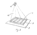
- Fig. 1 and Fig. 2 Simplified two micropanels 1 are shown, which are usually made of shipbuilding steel plates 2 with stapled steel profiles 3, whose area does not significantly exceed 3 mx 16 m.
- the micropanels shown are formed only schematically, usually the steel plates 2 are provided with burnouts 6 and undercuts and also the profiles 3 are present in larger numbers.
- micropanels 1 i. the profiles 3 and the steel plate 2 are welded by means of a robot, for example an articulated robot, whereby the welding is to be controlled automatically.
- a robot for example an articulated robot
- both the welding lines in the x-y plane, between profiles 3 and steel plate 2 and in the z-direction between the profiles 3 must be determined.
- the placed micropanel 1 is then scanned in the present exemplary embodiment with a 3D laser scanner, wherein, depending on the size of the work area to be detected, a sufficient number of partial exposures, depending on the recording field of the scanner, are triggered from different angles of incidence. Based on the known geometric relationships of the positions and orientations of the individual images with each other, a three-dimensional image of the working space with the panel 1 to be processed is created from these individual images. Thus, the overall picture is present as pixels in a three-dimensional coordinate system.
- the geometric data of the workpieces or of the micropanel 1 in the working space are then determined from the image data of the recorded scene.
- the environmental data are separated from the real workpiece data, wherein usually all measuring points above the plane of the construction of the work table workspaces and the points at or below this level are environmental points.
- the profiles of the profiles 3 on the plate surface are decisive for the position of the welds.
- the profile data resulting in the profile areas which penetrate the surface of the plate 2 must be filtered out.
- These penetration lines e.g. those in which profile levels and panel level penetrate correspond to the profile progressions.
- the pixels of the surface of the plate 2 are separated from the pixels of the surface of the profiles 3. Since the profile points will all be clearly above the level of the plate 2, the value of the z-coordinate can be used to differentiate and assign the points. By considering different height layers, the pixels can be uniquely divided into profile points and panel points by separating the coordinates above the panel plane.
- FIG. 1 and 2 is a simple form of a panel 1 shown, however, the shapes can be very diverse and complicated with recesses and undercuts.
- the contour of the panel 2 is determined.
- the panel points previously separated from the rest are combined so that the z coordinates are no longer different from each other. The that particular subpopulated cloud is then searched line by line and column by edge points.
- the profiles 3 which are the routes on which the profiles 3 are stapled with their footprints on the plate 2
- the distance between the points is taken into account, whereby the profile point cloud is searched line by line and column by column, similar to the search for the contour, in order to determine the structures or structure fragments from which the profile profiles are then combined by classification.
- intersections 4, 5 (see Fig. 2 ) of the profiles 3 with each other and their inner and outer sides are determined, as this determines the cutting edges at which the stitching seams that connect the profiles 3 together.
- the intersections are to be distinguished into one-sided 4 and two-sided 5. If two profile elements are in contact, the point of intersection is one-sided and two vertical welds are required, two profile elements intersect one another, the point is two-sided and four vertical weld seams are necessary.
- intersection lines that correspond to the profile attachment lines or their extension to the cutting of the two straight lines are the geometric basis for the course of the welds, which are arranged to the right and left of the interpolated straight line of the recognized profiles are. To find these, the material thickness of the profile is taken into account.
- the starting and ending points of the profiles concerned can be used as starting and ending points of the cutting line, whereby it is important that the found intersections of the profiles are taken into account as interruption of the line guidance.
- the vertical seams begin to weld the profiles together.
- the start and end point of the vertical seams is determined by the level of the panel level and the height of the detected profiles.
- the coordinates of the welds which are horizontal seams and stitching seams, have been found, they are given to the control of the welding robot.
- This control system assigns parameterizable movement patterns, so-called macros, assigned to the robot, wherein the respective weld seams are assigned to the stored macros with the aid of data transmitted as parameters.
- the macros are defined by the parameters, start and end coordinates, profile height and material thickness, among others. adapted to the conditions of the concrete weld.
- the specific commands for controlling the welding process such as switching on and off the gas supply, igniting the arc, activating the seam tracking, end crater filling and burn-back of the wire end are already stored in the macros.
- the execution order of the welds is automatically predetermined based on various, already stored, customizable criteria, but can be changed with interactive program input by the user.
- the device is provided with an image acquisition system which comprises an image acquisition module which receives the data of the image acquisition sensor and composes the point clouds of the individual images into an overall image of the workspace.
- a geometry recognition module determines the geometrical data of the workpieces in the workspace from the image data of the captured scene and the necessary weld data, and a controller containing a control algorithm performs the control of the welding process using the robot's control.
- a calibration module which performs the relationship between the coordinate systems of the robot, the image acquisition sensor and the construction gauge or the workpiece. It also includes the exact positions and orientations of the individual images for joining into a uniform image association. For this group of data a calibration algorithm is stored, which supports an interactive measurement. It also includes parameters and settings for optimizing geometry recognition.
- a calibration method of a three-dimensional image acquisition system is described, which is designed as a 3D laser scanner, but it is also possible for other types of image capture. This calibration procedure does not interfere with the laser scanner itself and the calibration itself is performed during or after installation of the system or routinely occurring inaccuracies.
- the image-capturing region 10 of the laser scanner 11 is defined by the frame 8 or the balls 7 lying on it outside.
- the nominal values of the centers of the reference balls 7 are in any coordinate system, ie in a by the arrangement according to Fig. 3 predetermined coordinate system known.
- the ball diameter is known.
- a central sphere is placed approximately at the center of the image capture area, ie at the center of the scanner's coordinate system. Subsequently, the reference spheres are picked up by the scanner and a point cloud of the reference spheres is generated in the plane work area to be calibrated.
- the actual values of the ball centers are determined by dividing this point cloud into individual partial point clouds, each containing the surface points of the individual spheres (segmentation). Subsequently, the ball centers are determined from the surface points of the individual balls by means of the method of least squares.
- the scanner 11 has as an image sensor a matrix of a multiplicity of pixels, which is referred to below as a scanner matrix.
- this matrix will be determines the row and column indices associated with the detected sphere centers, denoted by z_i, s_i, where i is the number of the respective sphere.
- the coordinate system of the target values of the center points designated as target data to the coordinate system of the actual values, ie, the ball centers, which were obtained from the point cloud recorded with the scanner, called actual data, aligned.
- This alignment is done via the plane defined by the ball centers each level, ie, the level of the actual data of the ball centers is brought into alignment with the plane of the target data of the ball centers and continue to be minimized in this level, then the distances between the target and actual data of the ball centers the center at the center of the scanner's coordinate system is used for this minimization.
- the nominal and actual data were essentially the same.
- the deviations ⁇ x z_i , s_i , ⁇ y z_i , s_i , ⁇ z z_i , s_i between setpoint and actual data of the ball centers are calculated and by interpolation / extrapolation three-dimensional first correction values of all pixel elements of the scanner matrix are determined corresponding to rows and columns.
- the data of the point cloud initially recorded with the scanner is corrected with the aid of the first correction values, and the actual values of the ball centers are again determined from the corrected point cloud of the scanner, as described above. Then be again determines the row and column indices of the scanner matrix for these determined ball centers and aligns the coordinate system of the desired data to the coordinate system of the actual data, as also described above. Then, the deviations between the desired and actual data of the ball centers are determined again and determined by interpolation / extrapolation three-dimensional second correction values of all pixel elements of the scanner matrix. By summing the first and second correction values result correction matrices Ax z, s, Ay z, s, z Az, s, which are used in the following measurements for each of the three-dimensional correction of the point cloud produced by the scanner.
- the accuracy of the laser scanner used was improved by a factor of about 10 for the required object distance of more than 3 m.
Description
Die Erfindung betrifft ein Verfahren zur Steuerung von Robotern zum Schweißen von dreidimensionalen Werkstücken.The invention relates to a method for controlling robots for welding three-dimensional workpieces.
Im Schiffbau werden Mikropaneele verwendet, die aus Stahlplatten und darauf verschweißten Versteifungsprofilen bestehen. In der Ausgangssituation werden diese Verstärkungsprofile unterschiedlicher Art auf die Stahlplatten geheftet und anschließend mit Knickarmrobotern oder Portalschweißanlagen abgeschweißt. Die Profile zeichnen sich durch unterschiedliche Profilformen, Abmessungen und Endbeschnitte aus, die Anordnung der Profile auf den Platten ist in jeglicher Weise möglich. Die Bewegungsprogrammierung der Schweißroboter zum Bahnschweißen stellt jedoch besonders bei geringen Stückzahlen, wie es bei den Mikropaneelen im Schiffsbau gegeben ist, einen unverhältnismäßig hohen Aufwand am gesamten, ansonsten automatisierten Fertigungsprozess dar.In shipbuilding, micropanels are used, which consist of steel plates and stiffening profiles welded to them. In the initial situation, these reinforcing profiles of different types are stapled to the steel plates and then welded with articulated robots or portal welding machines. The profiles are characterized by different profile shapes, dimensions and Endbeschnitte, the arrangement of the profiles on the plates is possible in any way. However, the movement programming of the welding robots for web welding is disproportionate, especially in the case of small quantities, as is the case with the micropanels in shipbuilding high expenditure on the entire, otherwise automated manufacturing process.
Zur Zeit basieren fast alle Programmiermethoden für das Schweißen von dreidimensionalen Werkstücken im Schiffsbau auf der Verfügbarkeit und anschließenden Konvertierung der jeweiligen CAD-Daten. Neben der Schnittstellenproblematik und den Kompatibilitätsproblemen verschiedener CAD-Programme und deren Ausgabedateien zum üblicherweise verwendeten CAM-Modul sind diese Programmiermethoden mit einer stark eingeschränkten Reaktionsmöglichkeit auf sich kurzfristig ändernde konstruktive oder technologische Merkmale des zu schweißenden Bauteils verbunden. Ändert sich ein Paneel kurzfristig, indem Profile fehlen, zusätzlich aufgebaut werden oder deren Anordnung verändert wird, so wird dennoch das ursprüngliche, nicht mehr aktuelle Roboterprogramm abgefahren. Ein weiteres Problem bei der bisherigen Arbeitsweise ist die Notwendigkeit der Werkstückausrichtung gemäß dem Roboterprogramm bzw. die Verschiebung und Umorientierung des Programms entsprechend der Bauteillage.At present, almost all programming methods for the welding of three-dimensional workpieces in shipbuilding are based on the availability and subsequent conversion of the respective CAD data. In addition to the interface problems and the compatibility problems of various CAD programs and their output files for the commonly used CAM module, these programming methods are associated with a very limited ability to react to short-term changing design or technological features of the component to be welded. If a panel changes in the short term, in that profiles are missing, additionally set up or their arrangement is changed, the original robot program, which is no longer up to date, is nevertheless skipped. Another problem with the previous operation is the need for workpiece alignment according to the robot program or the shift and reorientation of the program according to the component location.
Im Stand der Technik ist ein weiteres Verfahren zur Steuerung und Programmierung von Schweißrobotern bekannt (
Der nächstliegende Stand der Technik für die Erfindung wird durch die Druckschriften
Es ist aus den besagten Druckschriften also ein Verfahren zur Steuerung von Robotern zum Schweißen von dreidimensionalen Werkstücken mit folgenden Schritten:
- Positionieren und Heften von Profilen (3) auf eine Platte (2) zur Bildung des zu schweißenden Werkstücks (1),
- Abbilden des Werkstücks mittels eines dreidimensionalen Bilderfassungssystems in Form von dreidimensionalen Bildpunkten,
- Bestimmen von Geometriedaten,
- Bestimmen der Schweißnahtdaten aus den Geometriedaten unter Berücksichtigung der Profilaufsetzlinien und der Berührungslinien von Profilen,
- Zuordnen der Schweißnahtdaten zu parametrierbaren Vorgaben für den Schweißplan, zu gespeicherten vordefinierten Bewegungsmustern des Roboters sowie zu Befehlen zur Steuerung und Regelung des Schweißprozesses.
- Positioning and stapling profiles (3) on a plate (2) to form the workpiece (1) to be welded,
- Imaging the workpiece by means of a three-dimensional image acquisition system in the form of three-dimensional pixels,
- Determining geometry data,
- Determining the weld data from the geometry data taking into account the profile fitting lines and the contact lines of profiles,
- Assignment of the weld data to parameterizable specifications for the welding plan, to stored predefined motion patterns of the robot as well as to commands for controlling and regulating the welding process.
Der Erfindung liegt die Aufgabe zu Grunde, ein Verfahren zur Steuerung von Robotern zum Schweißen von dreidimensionalen Werkstücken zu schaffen, mit dem keine Verfügbarkeit von CAD-Daten des zu schweißenden Werkstücks notwendig ist, das Schweißnähte sowohl in horizontaler als auch vertikaler Richtung automatisch bestimmt und das eine flexible Reaktion auf sich kurzfristig ändernde konstruktive oder technologische Merkmale des zu schweißenden Werkstücks gestattet.The invention is based on the object to provide a method for controlling robots for welding three-dimensional workpieces, with no availability of CAD data of the workpiece to be welded is necessary, which automatically determines welds in both the horizontal and vertical direction and the allows a flexible response to short-term changing design or technological features of the workpiece to be welded.
Diese Aufgabe wird erfindungsgemäß durch die Merkmale des Hauptanspruchs gelöst.This object is achieved by the features of the main claim.
Durch die in den Unteransprüchen angegebenen Maßnahmen sind vorteilhafte Weiterbildungen und Verbesserungen möglich.The measures specified in the dependent claims advantageous refinements and improvements are possible.
Dadurch, dass das als eine Platte mit gehefteten Profilen ausgebildete zu schweißende Werkstück mittels eines dreidimensionalen Bilderfassungssystems in Form von dreidimensionalen Bildpunkten abgebildet wird und die Geometriedaten der Platte und der Profile aus den dreidimensionalen Bildpunkten bestimmt werden, aus den Geometriedaten unter Berücksichtigung der Profilaufsetzlinien und der Berührungslinien von Profilen die Schweißnahtdaten bestimmt werden und die Schweißnahtdaten gespeicherten, vordefinierten Bewegungsmustern des Roboters sowie Befehlen zur Steuerung des Schweißprozesses zugeordnet werden, kann als Verfahren zur Steuerung der Roboter ein Programm generiert werden, das unabhängig von den CAD-Daten des Werkstücks ist. Diese Art der zeit- und ortsnahen Programmerstellung umgeht Fehlermöglichkeiten, die durch technische oder technologische Änderungen in der Zeit zwischen Offline-Programmerstellung und Abarbeitung des Schweißauftrags auftreten können.Characterized in that the workpiece to be welded formed as a plate with stitched profiles is imaged by means of a three-dimensional image acquisition system in the form of three-dimensional pixels and the geometry data of the plate and the profiles are determined from the three-dimensional pixels, from the geometry data taking into account the profile placement lines and the contact lines Profiles determine the weld data and store the weld data, predefined motion patterns of the robot and commands to control the weld Welding process can be assigned as a method for controlling the robot, a program that is independent of the CAD data of the workpiece. This type of timely and local program creation bypasses error possibilities that due to technical or technological changes in the time between offline program generation and execution of the welding job.
Bei dem erfindungsgemäßen Verfahren liefert das Bilderfassungssystem direkt die für die weitere Verarbeitung benötigten Punktwolken (dreidimensionalen Bildpunkte) eines Messobjektes. Dies sind Matrizen mit n Zeilen, entsprechend der Anzahl der Messpunkte, und drei Spalten, entsprechend den drei Dimensionen des Raums. Direkt auf der Basis der dreidimensionalen Punktwolke erfolgt eine 3D-Geometriedatenverarbeitung, d.h. eine Segmentierung (Trennung der Punkte des Objektes von der Umgebung, Trennung der Punkte der Grundplatte von Punkten der Profile, Trennung der Punkte der Profile untereinander), eine Merkmalsextraktion (Feststellen von Profilverläufen aus der segmentierten Punktwolke), eine Untersuchung der Teilpunktewolken der einzelnen Profile nach Eigenschaften der Profile, wie Anfangs- und Endbeschnitten, Ausbränden bzw. Hinterschneidungen, Höhe oder dgl. Durch die 3D-Bilderfassung und 3D-Bildverarbeitung ist es möglich, die interaktiven Benutzereingaben zur Generierung der Schweißprogramme bzw. eine Kopplung an Konstruktionsdaten, die bei der 2D Messtechnik erforderlich sind, zu vermeiden. Damit kann ein nach dem erfindungsgemäßen Verfahren arbeitendes System als vollautomatisch angesehen werden.In the method according to the invention, the image acquisition system directly supplies the point clouds (three-dimensional pixels) required for further processing of a measurement object. These are matrices with n rows, corresponding to the number of measurement points, and three columns, corresponding to the three dimensions of the space. Directly on the basis of the three-dimensional point cloud, 3D geometry data processing, i. a segmentation (separation of the points of the object from the environment, separation of the points of the base of points of the profiles, separation of the points of the profiles among each other), a feature extraction (detection of profile progressions from the segmented point cloud), a study of the sub-point clouds of the individual profiles Properties of the profiles, such as start and end trimmings, burnouts, height or the like. Through 3D image acquisition and 3D image processing, it is possible to create the interactive user inputs for generating the welding programs or a coupling to design data, the 2D Measurement techniques are required to avoid. Thus, a system operating according to the invention can be regarded as fully automatic.
Die weiteren Vorteile können benannt werden zu: Programmerstellung unmittelbar vor der Abarbeitung; Programmerstellung anhand real vorliegender Bauteilgeometrien; beliebige Bauteilpositionierung und -orientierung; Berücksichtigung aller Raumkoordinaten, wodurch auch gleichzeitig Erreichbarkeiten und Kollisionsfreiheit sichergestellt werden. Das Verfahren ist leicht an bestehende Portalrobotersysteme adaptierbar und aufgrund des erfindungsgemäßen Verfahrens wird eine große Flexibilität in der Fertigung erreicht.The further advantages can be named to: program creation immediately before processing; Program creation based on real component geometries; any component positioning and orientation; Consideration of all spatial coordinates, whereby at the same time reachability and collision freedom are ensured. The procedure is easily adaptable to existing gantry robot systems and due to the method according to the invention a great flexibility in the production is achieved.
Zur Bilderfassung kann jegliche Sensoranordnung verwendet werden, die in der Lage ist, für jeden erfassten Objektpunkt die Koordinaten im Raum zu übergeben. Je höher die Auflösung der Daten, also die Punktedichte ist, umso besser ist die Detailerkennung. Vorteilhaft ist, das Abbild des Werkstücks mittels eines 3D Laserscanners zu erfassen, der aus mehreren Einzelaufnahmen ein räumliches digitales Modell des zu schweißenden Werkstücks liefert. Auch ist die Erfassung der dreidimensionalen Bildkoordinaten mit mindestens einem Musterprojektor und mindestens einer Kamera mit zugeordneter Auswertung möglich.For image acquisition, any sensor arrangement can be used which is capable of transferring the coordinates in space for each detected object point. The higher the resolution of the data, that is the point density, the better the detail recognition. It is advantageous to detect the image of the workpiece by means of a 3D laser scanner, which provides a spatial digital model of the workpiece to be welded from several individual recordings. Also, the detection of the three-dimensional image coordinates with at least one pattern projector and at least one camera with associated evaluation is possible.
Ein Ausführungsbeispiel des erfindungsgemäßen Verfahrens wird in der nachfolgenden Beschreibung unter Bezugnahme auf die beigefügte Zeichnung näher erläutert. Es zeigen
- Fig. 1
- eine perspektivische Ansicht eines als Mikropaneel ausgebildeten zu schweißenden Werkstücks,
- Fig. 2
- eine Aufsicht auf ein weiteres Werkstück, und
- Fig. 3
- eine Anordnung von Passmarken zum Kalibrieren des im Ausführungsbeispiel verwendeten Laserscanners.
- Fig. 1
- a perspective view of a formed as a micropanel to be welded workpiece,
- Fig. 2
- a top view of another workpiece, and
- Fig. 3
- an arrangement of registration marks for calibrating the laser scanner used in the embodiment.
In
Diese Mikropaneele 1 d.h. die Profile 3 und die Stahlplatte 2 werden mittels eines Roboters, beispielsweise eines Knickarmroboters verschweißt, wobei das Schweißen automatisch gesteuert werden soll. Dazu müssen sowohl die Schweißlinien in der x-y-Ebene, zwischen Profilen 3 und Stahlplatte 2 und in der z-Richtung zwischen den Profilen 3 bestimmt werden.These micropanels 1 i. the
Das platzierte Mikropaneel 1 wird dann im vorliegenden Ausführungsbeispiel mit einem 3D-Laserscanner abgetastet, wobei je nach Größe des zu erfassenden Arbeitsbereichs ausreichend viele Teilaufnahmen, abhängig vom Aufnahmefeld des Scanners aus unterschiedlichen Einfallswinkeln ausgelöst werden. Anhand der bekannten geometrischen Beziehungen der Positionen und Orientierungen der Einzelbilder untereinander wird aus diesen Einzelaufnahmen ein dreidimensionales Abbild des Arbeitsraums mit dem zu bearbeitenden Paneel 1 erstellt. Somit liegt das Gesamtbild als Bildpunkte in einem dreidimensionalen Koordinatensystem vor.The placed micropanel 1 is then scanned in the present exemplary embodiment with a 3D laser scanner, wherein, depending on the size of the work area to be detected, a sufficient number of partial exposures, depending on the recording field of the scanner, are triggered from different angles of incidence. Based on the known geometric relationships of the positions and orientations of the individual images with each other, a three-dimensional image of the working space with the
Aus den Bilddaten der aufgenommenen Szene werden dann die geometrischen Daten der Werkstücke bzw. des Mikropaneels 1 im Arbeitsraum ermittelt. Dazu werden die Umgebungsdaten von den realen Werkstückdaten getrennt, wobei in der Regel alle Messpunkte oberhalb der Ebene der Bauauflage des Arbeitstisches Werkstückpunkte und die Punkte auf oder unterhalb dieser Ebene Umgebungspunkte sind. Im Anschluss wird der Normalenvektor der Platte 2 bestimmt und die Koordinaten mit Hilfe dieses Vektors in ein Werkstückkoordinatensystem transformiert, dessen x-y-Ebene der Plattenebene entspricht und dessen z-Achse mit dem bestimmten Normalenvektor übereinstimmt.The geometric data of the workpieces or of the
Die Verläufe der Profile 3 auf der Plattenoberfläche sind bestimmend für die Lage der Schweißnähte. Um diese Verläufe zu ermitteln, müssen die Profildaten ausgefiltert werden, die die Profilflächen ergeben, welche die Oberfläche der Platte 2 durchdringen. Diese Durchdringungslinien z.B. diejenigen, in denen sich Profilebenen und Paneelebene durchdringen, entsprechen den Profilverläufen.The profiles of the
Um die Fläche der Profile zu bestimmen, werden die Bildpunkte der Oberfläche der Platte 2 von den Bildpunkten der Oberfläche der Profile 3 getrennt. Da die Profilpunkte alle eindeutig über dem Niveau der Platte 2 liegen werden, kann zum Unterscheiden und Zuordnen der Punkte der Wert der z-Koordinate herangezogen werden. Durch Betrachtung verschiedener Höhenschichten können durch Trennen der Koordinaten oberhalb der Paneelebene die Bildpunkte eindeutig in Profilpunkte und Paneel- bzw. Plattenpunkte aufgeteilt werden.In order to determine the area of the profiles, the pixels of the surface of the
In den
Zur Ermittlung der Aufsetzlinien der Profile 3, die die Strecken sind, auf denen die Profile 3 mit ihren Standflächen auf die Platte 2 geheftet sind, ist es notwendig, innerhalb der entsprechenden Bildpunkte der Profile zusammenhängende Strukturen zu ermitteln, um die Verläufe verschiedener Geraden voneinander trennen zu können. Dazu wird der Abstand zwischen den Punkten berücksichtigt, wobei die Profilpunktwolke ähnlich der Suche nach der Kontur zeilen- und spaltenweise durchsucht wird, um die Strukturen bzw. Strukturfragments zu bestimmen, aus denen dann durch Klassifizierung die Profilverläufe zusammengefasst werden.To determine the Aufsetzlinien the
Damit eindeutige Aussagen über den genauen Verlauf der späteren Schweißnähte getroffen werden können, müssen die Schnittpunkte 4, 5 (siehe
Die Schnittgeraden, die den Profil-Aufsetzlinien bzw. deren Verlängerung bis zum Schneiden der zwei Geraden entsprechen, sind die geometrische Basis für den Verlauf der Schweißnähte, die rechts und links von der interpolierten Geraden der erkannten Profile angeordnet sind. Um diese zu finden wird die Materialstärke des Profils berücksichtigt.The intersection lines that correspond to the profile attachment lines or their extension to the cutting of the two straight lines are the geometric basis for the course of the welds, which are arranged to the right and left of the interpolated straight line of the recognized profiles are. To find these, the material thickness of the profile is taken into account.
Als Anfangs- und Endpunkte der Schnittgeraden können die Anfangs- und Endpunkte der betroffenen Profile herangezogen werden, wobei wichtig ist, dass die gefundenen Schnittpunkte der Profile als Unterbrechung der Linienführung berücksichtigt werden. An diesen Punkten setzen die senkrechten Nähte zum Verschweißen der Profile untereinander an. Der Start- und Endpunkt der senkrechten Nähte ergibt sich aus dem Niveau der Paneelebene und der Höhe der erkannten Profile.The starting and ending points of the profiles concerned can be used as starting and ending points of the cutting line, whereby it is important that the found intersections of the profiles are taken into account as interruption of the line guidance. At these points, the vertical seams begin to weld the profiles together. The start and end point of the vertical seams is determined by the level of the panel level and the height of the detected profiles.
Nachdem die Koordinaten der Schweißnähte, die waagerechte Nähte sowie Steignähte sind, gefunden wurden, werden diese an die Steuerung des Schweißroboters gegeben. Diese Steuerung weist dem Roboter zugeordnete, parametrierbare Bewegungsmuster, sogenannte Makros, zu, wobei mit Hilfe als Parameter übergebenen Daten die jeweiligen Schweißnähte den hinterlegten Makros zugeordnet werden, d.h. die Makros werden mittels der Parameter, Start- und Endkoordinaten, Profilhöhe und Materialstärke u.a. an die Bedingungen der konkreten Schweißnaht angepasst. Die spezifischen Befehle zur Steuerung des Schweißprozesses, wie Ein- und Ausschalten der Gaszufuhr, Zünden des Lichtbogens, Aktivierung der Nahtverfolgung, Endkraterfüllung und Rückbrennen des Drahtendes sind bereits in den Makros gespeichert.After the coordinates of the welds, which are horizontal seams and stitching seams, have been found, they are given to the control of the welding robot. This control system assigns parameterizable movement patterns, so-called macros, assigned to the robot, wherein the respective weld seams are assigned to the stored macros with the aid of data transmitted as parameters. The macros are defined by the parameters, start and end coordinates, profile height and material thickness, among others. adapted to the conditions of the concrete weld. The specific commands for controlling the welding process, such as switching on and off the gas supply, igniting the arc, activating the seam tracking, end crater filling and burn-back of the wire end are already stored in the macros.
Für zusätzliche Funktionen, wie z.B. Kollisionskontrollen, werden Höhe und Materialstärke der einzelnen Profile 3 an die Steuerung gegeben und bei dem Schweißen berücksichtigt.For additional functions, such as Collision checks, height and material thickness of each
Die Abarbeitungsreihenfolge der Schweißnähte (Schweißplan) wird anhand verschiedener, bereits hinterlegter, anpassbarer Kriterien automatisch vorbestimmt, kann aber mit interaktiver Programmeingabe durch den Anwender geändert werden.The execution order of the welds (Welding plan) is automatically predetermined based on various, already stored, customizable criteria, but can be changed with interactive program input by the user.
Wie schon oben ausgeführt wurde, ist die erfindungsgemäße Vorrichtung mit einem Bilderfassungssystem versehen, das ein Bilderfassungsmodul umfasst, das die Daten des Bilderfassungssensors empfängt und die Punktewolken der Einzelbilder zu einem Gesamtbild des Arbeitsraums zusammensetzt. Ein Geometrieerkennungsmodul ermittelt, wie oben ausgeführt, die geometrischen Daten der Werkstücke im Arbeitsraum aus den Bilddaten der aufgenommenen Szene und die notwendigen Schweißnahtdaten und eine einen Steuerungsalgorithmus enthaltende Steuereinrichtung führt die Steuerung/Regelung des Schweißprozesses unter Heranziehung der Steuerung des Roboters durch.As already stated above, the device according to the invention is provided with an image acquisition system which comprises an image acquisition module which receives the data of the image acquisition sensor and composes the point clouds of the individual images into an overall image of the workspace. As noted above, a geometry recognition module determines the geometrical data of the workpieces in the workspace from the image data of the captured scene and the necessary weld data, and a controller containing a control algorithm performs the control of the welding process using the robot's control.
Zusätzlich ist ein Kalibriermodul vorgesehen, der den Zusammenhang zwischen den Koordinatensystemen des Roboters, des Bilderfassungssensors und der Baulehre bzw. des Werkstücks durchführt. Es beinhaltet zusätzlich die exakten Positionen und Orientierungen der Einzelbilder für das Zusammenfügen zu einem einheitlichen Bildverband. Für diese Gruppe von Daten ist ein Kalibrieralgorithmus hinterlegt, der eine interaktive Vermessung unterstützt. Weiterhin umfasst es Parameter und Einstellungen zur Optimierung der Geometrieerkennung.In addition, a calibration module is provided, which performs the relationship between the coordinate systems of the robot, the image acquisition sensor and the construction gauge or the workpiece. It also includes the exact positions and orientations of the individual images for joining into a uniform image association. For this group of data a calibration algorithm is stored, which supports an interactive measurement. It also includes parameters and settings for optimizing geometry recognition.
Im Folgenden wird ein Kalibrierverfahren eines dreidimensionalen Bilderfassungssystems beschrieben, das als 3D-Laserscanner ausgebildet ist, wobei es aber auch für andere Arten der Bilderfassung möglich ist. Bei diesem Kalibrierverfahren wird kein Eingriff in den Laserscanner an sich vorgenommen und die Kalibrierung selbst wird bei bzw. nach Installation der Anlage bzw. routinemäßig bei auftretenden Maßungenauigkeiten durchgeführt.In the following, a calibration method of a three-dimensional image acquisition system is described, which is designed as a 3D laser scanner, but it is also possible for other types of image capture. This calibration procedure does not interfere with the laser scanner itself and the calibration itself is performed during or after installation of the system or routinely occurring inaccuracies.
Zur Kalibrierung werden entsprechend
Aus der Punktwolke werden die Istwerte der Kugelmittelpunkte ermittelt, indem diese Punktwolke in einzelne Teilpunktwolken aufgeteilt wird, die jeweils die Oberflächenpunkte der einzelnen Kugeln enthalten (Segmentierung). Anschließend werden die Kugelmittelpunkte aus den Oberflächenpunkten der einzelnen Kugeln mit Hilfe des Verfahrens der kleinsten Fehlerquadrate bestimmt.From the point cloud, the actual values of the ball centers are determined by dividing this point cloud into individual partial point clouds, each containing the surface points of the individual spheres (segmentation). Subsequently, the ball centers are determined from the surface points of the individual balls by means of the method of least squares.
Der Scanner 11 weist als Bildsensor eine Matrix aus einer Vielzahl von Pixeln auf, die im Folgenden als Scannermatrix bezeichnet wird. In dieser Matrix werden die zu den ermittelten Kugelmittelpunkten gehörenden Zeilen- und Spaltenindices bestimmt, die mit z_i, s_i bezeichnet werden, wobei i die Nummer der jeweiligen Kugel ist. Dann wird das Koordinatensystem der Sollwerte der Mittelpunkte, bezeichnet als Solldaten zu dem Koordinatensystem der Istwerte, d.h., der Kugelmittelpunkte, die aus der mit dem Scanner aufgenommenen Punktewolke gewonnen wurden, genannt Istdaten, ausgerichtet. Diese Ausrichtung geschieht über die von den Kugelmittelpunkten jeweils aufgespannten Ebenen, d.h., die Ebene der Istdaten der Kugelmittelpunkte wird mit der Ebene der Solldaten der Kugelmittelpunkte in Ausrichtung gebracht und weiterhin werden in dieser Ebene dann die Abstände zwischen Soll- und Istdaten der Kugelmittelpunkte minimiert, wobei die Zentrale im Mittelpunkt des Koordinatensystems des Scanners für diese Minimierung herangezogen wird. Bei dieser zentralen Kugel stimmten die Soll- und Istdaten im Wesentlichen überein.The scanner 11 has as an image sensor a matrix of a multiplicity of pixels, which is referred to below as a scanner matrix. In this matrix will be determines the row and column indices associated with the detected sphere centers, denoted by z_i, s_i, where i is the number of the respective sphere. Then, the coordinate system of the target values of the center points, designated as target data to the coordinate system of the actual values, ie, the ball centers, which were obtained from the point cloud recorded with the scanner, called actual data, aligned. This alignment is done via the plane defined by the ball centers each level, ie, the level of the actual data of the ball centers is brought into alignment with the plane of the target data of the ball centers and continue to be minimized in this level, then the distances between the target and actual data of the ball centers the center at the center of the scanner's coordinate system is used for this minimization. For this central sphere, the nominal and actual data were essentially the same.
Anschließend werden die Abweichungen Δxz_i,s_i, Δyz_i,s_i, Δzz_i,s_i zwischen Soll- und Istdaten der Kugelmittelpunkte berechnet und durch Interpolation/Extrapolation werden dreidimensionale erste Korrekturwerte aller Pixelelemente der Scannermatrix entsprechend Zeilen und Spalten ermittelt.Subsequently, the deviations Δx z_i , s_i , Δy z_i , s_i , Δz z_i , s_i between setpoint and actual data of the ball centers are calculated and by interpolation / extrapolation three-dimensional first correction values of all pixel elements of the scanner matrix are determined corresponding to rows and columns.
Es hat sich gezeigt, dass die Genauigkeit mit dem Kalibrierverfahren entsprechend den obigen Schritten noch nicht ganz befriedigend ist, so dass ein weiterer Kalibriervorgang vorgenommen wird. Dazu werden die Daten der mit dem Scanner anfangs aufgenommenen Punktwolke mit Hilfe der ersten Korrekturwerte korrigiert und es werden erneut die Istwerte der Kugelmittelpunkte aus der korrigierten Punktwolke des Scanners, wie oben beschrieben, ermittelt. Dann werden wiederum die Zeilen- und Spaltenindices der Scannermatrix für diese ermittelten Kugelmittelpunkte bestimmt und das Koordinatensystem der Solldaten zu dem Koordinatensystem der Istdaten, wie gleichfalls oben beschrieben, ausgerichtet. Dann werden die Abweichungen zwischen den Soll- und Istdaten der Kugelmittelpunkte erneut bestimmt und durch Interpolation/Extrapolation dreidimensionale zweite Korrekturwerte aller Pixelelemente der Scannermatrix ermittelt. Durch Summierung der ersten und zweiten Korrekturwerte ergeben sich Korrekturmatrizen Δxz,s, Δyz,s, Δzz,s, die bei den folgenden Messungen jeweils für die dreidimensionale Korrektur der vom Scanner erzeugten Punktwolke herangezogen werden.It has been found that the accuracy with the calibration method according to the above steps is still not completely satisfactory, so that a further calibration process is performed. For this purpose, the data of the point cloud initially recorded with the scanner is corrected with the aid of the first correction values, and the actual values of the ball centers are again determined from the corrected point cloud of the scanner, as described above. Then be again determines the row and column indices of the scanner matrix for these determined ball centers and aligns the coordinate system of the desired data to the coordinate system of the actual data, as also described above. Then, the deviations between the desired and actual data of the ball centers are determined again and determined by interpolation / extrapolation three-dimensional second correction values of all pixel elements of the scanner matrix. By summing the first and second correction values result correction matrices Ax z, s, Ay z, s, z Az, s, which are used in the following measurements for each of the three-dimensional correction of the point cloud produced by the scanner.
Mit Hilfe eines solchen Kalibrierverfahrens wurde die Genauigkeit des verwendeten Laserscanners bei der erforderlichen Objektentfernung von mehr als 3 m um einen Faktor von ca. 10 verbessert werden.With the aid of such a calibration method, the accuracy of the laser scanner used was improved by a factor of about 10 for the required object distance of more than 3 m.
Claims (17)
- Method for controlling robots for welding three-dimensional workpieces, having the following steps:positioning and tack-welding profiles (3) onto a plate (2) in order to form the workpiece (1) to be welded,positioning the plate on a work table,imaging the workpiece by means of a three-dimensional image detection system in the form of three-dimensional pixels,determining the geometrical data of the plate and of the profiles directly from the three-dimensional pixels as a pixel cloud by segmenting it according to the background and the workpiece, plate (2) and profiles (3) and profiles (3) from each other, by establishing profile courses and examining the individual profiles according to their properties including cutouts and end cut edges from the segmented three-dimensional pixels, wherein the position of the plate plane is determined and the measuring points of the workpiece are transformed into a local workpiece coordinate system, the x-y plane of which coincides with the plane of the plate, thereby separating the pixels of the plate plane and the pixels of the profiles using height coordinates,determining the weld seam data from the geometrical data taking into account the profile placement lines and the contact lines of profiles,assigning the weld seam data to parameterisable specifications for the welding plan to stored predefined movement patterns of the robot and also to commands for controlling and regulating the welding process.
- Method according to claim 1, characterised in that the image of the workpiece (1) is detected by means of a 3D laser scanner or by means of a projection of patterns and at least one camera with assigned evaluation.
- Method according to claim 1 or claim 2, characterised in that the determination of the geometrical data is effected by 3D processing.
- Method according to claim 3, characterised in that the contours of the plate are determined in order to delimit workpiece and background.
- Method according to claim 3 or claim 4, characterised in that the pixels of the profiles are pre-sorted according to coherent structures.
- Method according to claim 5, characterised in that linear profile courses are determined from the pixels of the coherent structures.
- Method according to claim 6, characterised in that the profile placement lines and the contact lines of profiles are determined from the linear profile courses and also from the position of the plate plane.
- Method according to one of the claims 1 to 7, characterised in that the image detection system is calibrated by the following steps:a) disposing reference balls in a plane with respect to the workpiece to be welded later, the reference values of the centres of the reference balls in an arbitrary coordinate system and at least one parameter for controlling the calibration method being prescribed,b) producing a point cloud of the reference balls with the image detection system and determining the actual values of the ball centres in the coordinate system assigned to the actual values,c) orientating the coordinate system of the reference values to the coordinate system of the actual values,d) calculating the three-dimensional deviations between the reference and actual values of the ball centres,e) determining three-dimensional first correction values for coordinates of the image detection region by interpolation/extrapolation.
- Method according to claim 8, characterised in that the point cloud photographed in step b) is corrected with the help of the first correction values and corrected actual values of the ball centres are determined, steps c) and d) are repeated and three-dimensional second correction values for the coordinates of the image detection system are determined by interpolation/extrapolation, the sum of the first and second correction values being formed in order to determine three-dimensional correction values for the image detection system.
- Method according to claim 8 or claim 9, the image detection system being a laser scanner with a scanner matrix as image detection sensor, characterised in that line and column indices of the scanner matrix which are associated with the determined ball centres are determined between steps b) and c) and in that the three-dimensional first correction values are determined for all pixel elements of the scanner matrix.
- Method according to one of the claims 8 to 10, characterised in that in order to determine the second correction values, also the step of determining the column and line indices of the scanner matrix which are associated with the corrected actual values of the ball centres is repeated and in that three-dimensional correction matrices are formed for the scanner from the sum of the first and second correction values.
- Method according to one of the claims 8 or 11, characterised in that the actual values of the ball centres are determined by dividing the point cloud into individual partial point clouds, determining the coordinates of the surface points and calculating the centres of the individual balls with the help of the method of the smallest error squares.
- Method according to one of the claims 8 to 10, characterised in that the orientation according to step d) is implemented by orientating via the plane spanned by the ball centres and, in this plane, an orientation is undertaken by minimising the spacings between reference and actual values of the ball centres and also via a central ball placed in the centre of the coordinate system of the actual values.
- Device for controlling robots for welding three-dimensional workpieces, comprising
an image detection system for detecting a three-dimensional image of a workpiece to be welded which has profiles tack-welded onto a plate positioned on a work table, and for delivering image data as pixels,
a geometry recognition module configured for determining the geometrical data of the plate and of the profiles directly from the three-dimensional pixels as a pixel cloud by segmenting it according to the background and the workpiece, plate (2) and profiles (3) and profiles (3) from each other, by establishing profile courses and examining the individual profiles according to their properties including cut outs and end cut edges from the segmented three-dimensional pixels, so that the position of the plate plane is determined and the measuring points of the workpiece are transformed into a local workpiece coordinate system, the x-y plane of which coincides with the plane of the plate, thereby separating the pixels of the plate plane and the pixels of the profiles using height coordinates" and
a control device which contains a control algorithm for assigning the weld seam data to parameterisable specifications for the welding plan, to stored predefined movement patterns of the robot and also to commands for controlling/regulating the welding process. - Device according to claim 14, characterised in that the image detection system has a 3D laser scanner which delivers a spatial digital model of the workpiece to be welded from several individual photographs.
- Method according to claim 14 or claim 15, characterised in that a calibration module for geometrical correlation of the coordinate systems of the robot, the image detection system and the workpiece to be welded is provided.
- Method according to claim 16, characterised in that the calibration module contains a calibration algorithm corresponding to the method according to one of the claims 8 to 13.
Applications Claiming Priority (2)
| Application Number | Priority Date | Filing Date | Title |
|---|---|---|---|
| DE102007008598A DE102007008598A1 (en) | 2007-02-19 | 2007-02-19 | Automatic programming of robots to weld stapled profiles onto micropanels using digital image capture |
| PCT/EP2008/001618 WO2008101737A1 (en) | 2007-02-19 | 2008-02-19 | Method and device for controlling robots for welding workpieces |
Publications (2)
| Publication Number | Publication Date |
|---|---|
| EP2132608A1 EP2132608A1 (en) | 2009-12-16 |
| EP2132608B1 true EP2132608B1 (en) | 2015-01-28 |
Family
ID=39391430
Family Applications (1)
| Application Number | Title | Priority Date | Filing Date |
|---|---|---|---|
| EP08716141.0A Active EP2132608B1 (en) | 2007-02-19 | 2008-02-19 | Method and device for controlling robots for welding workpieces |
Country Status (7)
| Country | Link |
|---|---|
| US (1) | US8338743B2 (en) |
| EP (1) | EP2132608B1 (en) |
| JP (1) | JP5429872B2 (en) |
| KR (1) | KR101051863B1 (en) |
| CN (1) | CN101657767B (en) |
| DE (1) | DE102007008598A1 (en) |
| WO (1) | WO2008101737A1 (en) |
Families Citing this family (64)
| Publication number | Priority date | Publication date | Assignee | Title |
|---|---|---|---|---|
| DE102008025647A1 (en) * | 2008-05-28 | 2009-12-17 | Lfk-Lenkflugkörpersysteme Gmbh | Stapling seam-free welding in the seam outer areas of components |
| US8923602B2 (en) * | 2008-07-22 | 2014-12-30 | Comau, Inc. | Automated guidance and recognition system and method of the same |
| DE102008038988B3 (en) * | 2008-08-13 | 2009-09-17 | Kraussmaffei Technologies Gmbh | Combined plastics die cutter and trimmer has robotic laser arm directed between moving upper and fixed lower tools |
| DE102009041734B4 (en) * | 2009-09-16 | 2023-11-02 | Kuka Roboter Gmbh | Measuring a manipulator |
| EP2409808A1 (en) * | 2010-07-22 | 2012-01-25 | Bystronic Laser AG | Laser processing machine |
| CN102259339A (en) * | 2011-02-23 | 2011-11-30 | 山东华兴机械股份有限公司 | Manipulator |
| US10888947B2 (en) | 2011-06-27 | 2021-01-12 | Illinois Tool Works Inc. | Workpiece-based setting of weld parameters |
| WO2013018114A1 (en) * | 2011-08-03 | 2013-02-07 | D.G. Weld S.R.L. | Regeneration system for a forge die |
| US9266182B2 (en) | 2012-04-06 | 2016-02-23 | Illinois Tools Works Inc. | Welding torch with a temperature measurement device |
| US9415459B2 (en) | 2012-04-06 | 2016-08-16 | Illinois Tool Works Inc. | Welding systems having non-contact temperature measurement systems |
| US9878393B2 (en) | 2012-06-08 | 2018-01-30 | Illinois Tool Works Inc. | Welding wire feeder power control system and method |
| US10682720B2 (en) | 2012-09-07 | 2020-06-16 | Illinois Tool Works Inc. | Welding systems and devices having a configurable personal computer user interface |
| US10203683B2 (en) | 2013-07-16 | 2019-02-12 | Seagate Technology Llc | Coordinating end effector and vision controls |
| EP2883647B1 (en) | 2013-12-12 | 2019-05-29 | Bystronic Laser AG | Method for configuring a laser machining device |
| US9233469B2 (en) | 2014-02-13 | 2016-01-12 | GM Global Technology Operations LLC | Robotic system with 3D box location functionality |
| US11103948B2 (en) | 2014-08-18 | 2021-08-31 | Illinois Tool Works Inc. | Systems and methods for a personally allocated interface for use in a welding system |
| CN104384765B (en) * | 2014-10-14 | 2016-04-27 | 江苏湃锐自动化科技有限公司 | Based on the automatic soldering method of threedimensional model and machine vision |
| CN107407719B (en) * | 2015-03-26 | 2020-12-25 | 株式会社村田制作所 | Position detection method for moving body |
| JP7353757B2 (en) | 2015-07-13 | 2023-10-02 | レニショウ パブリック リミテッド カンパニー | Methods for measuring artifacts |
| WO2017012117A1 (en) * | 2015-07-23 | 2017-01-26 | Abb Schweiz Ag | Method and apparatus of scheduling welding operations |
| EP3325205B1 (en) | 2015-07-23 | 2021-01-20 | ABB Schweiz AG | Method and apparatus of identifying welding seams of welding object |
| JP6612454B2 (en) | 2016-03-28 | 2019-11-27 | アーベーベー・シュバイツ・アーゲー | Method, system, and apparatus for determining search parameters for weld seam point calibration |
| CN106180965A (en) * | 2016-07-18 | 2016-12-07 | 上海发那科机器人有限公司 | The laser scanning welder of a kind of robot and method |
| CN107876953B (en) * | 2016-09-29 | 2022-04-22 | 福特环球技术公司 | Splicer with position guidance system |
| JP6914067B2 (en) * | 2017-03-21 | 2021-08-04 | 株式会社神戸製鋼所 | Motion program correction method and welding robot system |
| JP6817122B2 (en) * | 2017-03-21 | 2021-01-20 | 株式会社神戸製鋼所 | Welding path identification method, program, teaching program and welding robot system |
| JP6877689B2 (en) * | 2017-03-27 | 2021-05-26 | カシオ計算機株式会社 | Programming device and its control program, programming method |
| EP3630404B1 (en) * | 2017-05-24 | 2024-01-03 | Inrotech Aps | An apparatus and a method for automated seam welding of a work piece comprising a base plate with a pattern of upstanding profiles |
| CN109890690A (en) * | 2017-09-29 | 2019-06-14 | 常石造船株式会社 | Seam configuration method, seam configuration device and seam configurator |
| CN111727100B (en) * | 2018-02-26 | 2022-05-17 | 株式会社日立制作所 | Welding action measuring system |
| NL2020860B1 (en) * | 2018-05-02 | 2019-11-12 | Exner Ingenieurstechniek B V | Method of, as well as a system for, performing a welding step on a work piece. |
| US11440119B2 (en) | 2018-10-12 | 2022-09-13 | Teradyne, Inc. | System and method for weld path generation |
| CN109367693B (en) * | 2018-10-25 | 2022-03-15 | 上海船舶工艺研究所(中国船舶工业集团公司第十一研究所) | Allowance-free installation method for large equipment base for ship |
| KR102125167B1 (en) * | 2019-01-21 | 2020-06-19 | 한양대학교 에리카산학협력단 | Automatic welding device, working method thereof |
| CN110057338B (en) * | 2019-05-24 | 2021-04-20 | 福建工程学院 | Workpiece origin self-adaptive setting method based on composite measurement |
| CN110508906A (en) * | 2019-08-30 | 2019-11-29 | 上海发那科机器人有限公司 | A kind of method that robotic laser displacement sensor seeks position |
| CN110524580B (en) * | 2019-09-16 | 2023-06-02 | 西安中科光电精密工程有限公司 | Welding robot vision assembly and measuring method thereof |
| DE102020104362B4 (en) | 2020-02-19 | 2022-04-14 | Franka Emika Gmbh | Path planning for a robot manipulator using a camera image |
| CN111427591B (en) * | 2020-03-19 | 2023-06-02 | Oppo(重庆)智能科技有限公司 | Program offline manufacturing method and device, storage medium and electronic equipment |
| TWI764130B (en) * | 2020-04-13 | 2022-05-11 | 迅智自動化科技股份有限公司 | Welding system and welding parameter optimization method |
| US20210316382A1 (en) * | 2020-04-14 | 2021-10-14 | Huys Industries Limited | Welded assembly and method of welding using electro-spark discharge |
| JP6985464B1 (en) * | 2020-07-06 | 2021-12-22 | ジャパンマリンユナイテッド株式会社 | Welding robot motion automatic generation method and motion automatic generation system |
| US11407110B2 (en) * | 2020-07-17 | 2022-08-09 | Path Robotics, Inc. | Real time feedback and dynamic adjustment for welding robots |
| CN112001935B (en) * | 2020-07-28 | 2023-07-18 | 上海巧视智能科技有限公司 | T-shaped weld polishing method, system, medium and terminal based on laser scanning |
| CN112846577A (en) * | 2020-12-25 | 2021-05-28 | 郑智宏 | Method for improving welding automation |
| CA3211502A1 (en) | 2021-02-24 | 2022-09-01 | Path Robotics, Inc. | Autonomous welding robots |
| KR102452430B1 (en) * | 2021-02-26 | 2022-10-06 | 한국로봇융합연구원 | Apparatus and method for recognizing welding targets based on vision |
| CN113119122B (en) * | 2021-04-10 | 2022-11-22 | 西北工业大学 | Hybrid off-line programming method of robot welding system |
| CN113399793A (en) * | 2021-06-15 | 2021-09-17 | 广东开放大学(广东理工职业学院) | Thin-wall titanium tube robot welding method |
| CN113687365B (en) * | 2021-06-30 | 2023-12-22 | 云南昆钢电子信息科技有限公司 | Multi-height layer contour recognition and coordinate calculation method and system based on quasi-plane |
| CN113533498A (en) * | 2021-07-26 | 2021-10-22 | 成都盛锴科技有限公司 | Welding seam detection positioning method and positioning device of automatic eddy current flaw detection system |
| CN113601306B (en) * | 2021-08-04 | 2022-07-08 | 上海电器科学研究所(集团)有限公司 | Charging facility box body weld joint polishing method based on one-dimensional segmentation network |
| CN113793344B (en) * | 2021-08-31 | 2023-09-29 | 无锡砺成智能装备有限公司 | Impeller weld joint positioning method based on three-dimensional point cloud |
| US20230096097A1 (en) * | 2021-09-24 | 2023-03-30 | Daihen Corporation | Welding Line Detection System |
| KR20230043706A (en) * | 2021-09-24 | 2023-03-31 | 가부시키가이샤 다이헨 | Work program creating system and work program creating method |
| CN113643372B (en) * | 2021-10-18 | 2022-03-04 | 中国科学院自动化研究所 | Three-dimensional weld extraction method and system |
| JP2023070565A (en) * | 2021-11-09 | 2023-05-19 | 株式会社日立製作所 | Welding pass autonomous optimization device, welding pass autonomous optimization system, and welding pass autonomous optimization method |
| CN114055004A (en) * | 2021-12-17 | 2022-02-18 | 宝武重工有限公司 | Intelligent welding method for steel structure welding robot |
| KR102424501B1 (en) * | 2022-04-25 | 2022-07-25 | 주식회사 미주산업 | Vision recognition-based shipbuilding equipment robot welding automation system |
| WO2024045120A1 (en) * | 2022-09-01 | 2024-03-07 | Squaredog Robotics Limited | System and method for self-adjustable welding |
| CN115179302B (en) * | 2022-09-13 | 2022-12-13 | 北京石油化工学院 | Control method for locating, planning and correcting welding robot in nuclear environment |
| CN115810133B (en) * | 2023-02-09 | 2023-05-23 | 中建科技集团有限公司 | Welding control method based on image processing and point cloud processing and related equipment |
| CN116652440B (en) * | 2023-07-31 | 2023-10-20 | 中建安装集团西安建设投资有限公司 | Digital welding method and control system for steel structure |
| CN117583771B (en) * | 2024-01-19 | 2024-03-15 | 广州森弘信息科技有限公司 | Welding method and system based on directional reference and multi-axis welding robot |
Family Cites Families (18)
| Publication number | Priority date | Publication date | Assignee | Title |
|---|---|---|---|---|
| US5579444A (en) * | 1987-08-28 | 1996-11-26 | Axiom Bildverarbeitungssysteme Gmbh | Adaptive vision-based controller |
| DE4115846A1 (en) * | 1991-05-15 | 1992-11-19 | Ameling Walter | Contactless spatial position measurement in robot processing chamber - acquiring images of robotic actuator with defined marking enabling calibration of imaging units in coordinate system |
| US6226395B1 (en) * | 1996-04-22 | 2001-05-01 | Malcolm T. Gilliland | Method and apparatus for determining the configuration of a workpiece |
| US5991437A (en) * | 1996-07-12 | 1999-11-23 | Real-Time Geometry Corporation | Modular digital audio system having individualized functional modules |
| JP3517529B2 (en) * | 1996-08-21 | 2004-04-12 | 株式会社東芝 | Image input type robot system |
| DE19829661A1 (en) * | 1998-07-02 | 1999-04-22 | Georg Prof Stark | Computer-aided robot control sequence generation method |
| JP3327854B2 (en) * | 1998-12-28 | 2002-09-24 | 川崎重工業株式会社 | Teaching method and teaching device for welding robot |
| FI117005B (en) * | 2000-08-29 | 2006-05-15 | Aker Finnyards Oy | Arrangement and method of welding |
| DE10115149B4 (en) * | 2001-03-27 | 2004-07-29 | Vmt Bildverarbeitungssysteme Gmbh | Reintegration of a digital camera into an image processing system which has been moved from a calibrated position to an uncalibrated position |
| JP4641643B2 (en) * | 2001-03-30 | 2011-03-02 | セイコーインスツル株式会社 | Delay circuit |
| US7143494B2 (en) * | 2001-05-16 | 2006-12-05 | Utica Enterprises, Inc. | Method and apparatus for assembling exterior automotive vehicle body components onto an automotive vehicle body |
| JP2003223213A (en) * | 2002-01-31 | 2003-08-08 | Nippei Toyama Corp | Teaching method and apparatus, and laser processing machine provided with the teaching method |
| EP1361414B1 (en) | 2002-05-08 | 2011-01-26 | 3D Scanners Ltd | Method for the calibration and qualification simultaneously of a non-contact probe |
| SE524818C2 (en) * | 2003-02-13 | 2004-10-05 | Abb Ab | A method and system for programming an industrial robot to move relatively defined positions on an object |
| JP3950805B2 (en) * | 2003-02-27 | 2007-08-01 | ファナック株式会社 | Teaching position correction device |
| FI117426B (en) * | 2003-06-12 | 2006-10-13 | Aker Yards Oy | A method for controlling welding of a three-dimensional structure |
| JP4795700B2 (en) * | 2005-02-22 | 2011-10-19 | 三菱重工業株式会社 | Bending method, metal plate, heating position determination program, and heating position determination device |
| US8923602B2 (en) * | 2008-07-22 | 2014-12-30 | Comau, Inc. | Automated guidance and recognition system and method of the same |
-
2007
- 2007-02-19 DE DE102007008598A patent/DE102007008598A1/en not_active Ceased
-
2008
- 2008-02-19 CN CN200880005452.1A patent/CN101657767B/en active Active
- 2008-02-19 KR KR1020097017929A patent/KR101051863B1/en active IP Right Grant
- 2008-02-19 JP JP2009549805A patent/JP5429872B2/en active Active
- 2008-02-19 EP EP08716141.0A patent/EP2132608B1/en active Active
- 2008-02-19 US US12/449,595 patent/US8338743B2/en active Active
- 2008-02-19 WO PCT/EP2008/001618 patent/WO2008101737A1/en active Application Filing
Also Published As
| Publication number | Publication date |
|---|---|
| WO2008101737A1 (en) | 2008-08-28 |
| CN101657767B (en) | 2014-01-15 |
| US20100152870A1 (en) | 2010-06-17 |
| DE102007008598A1 (en) | 2008-08-21 |
| JP2010519056A (en) | 2010-06-03 |
| KR101051863B1 (en) | 2011-07-25 |
| JP5429872B2 (en) | 2014-02-26 |
| US8338743B2 (en) | 2012-12-25 |
| KR20090117757A (en) | 2009-11-12 |
| CN101657767A (en) | 2010-02-24 |
| EP2132608A1 (en) | 2009-12-16 |
Similar Documents
| Publication | Publication Date | Title |
|---|---|---|
| EP2132608B1 (en) | Method and device for controlling robots for welding workpieces | |
| EP3108311B1 (en) | Method, machining unit and computer program product for the image-based positioning of workpiece machining operations | |
| DE112010000794B4 (en) | Method for controlling a robot tool | |
| EP3084347B1 (en) | Method for carrying out and checking a machining step on a workpiece | |
| DE102015013161B4 (en) | Device for setting an interference range of a robot | |
| DE102019215749B4 (en) | IMAGE CAPTURE DEVICE AND MACHINE TOOL | |
| DE602004005776T2 (en) | A method of controlling the welding of a three-dimensional structure with the capture of a two-dimensional image of the structure and with real-time alignments in the third dimension | |
| DE102018009023B4 (en) | Teaching device for carrying out robot teaching processes and teaching methods | |
| DE102015012763B4 (en) | Robot teaching device for teaching a robot offline | |
| WO2020127797A1 (en) | Method for providing geometrical sheet-planning data, method and flatbed laser machine for cutting out workpieces | |
| DE102021103726B4 (en) | Measurement parameter optimization method and device and computer control program | |
| EP3221094B1 (en) | Method and system for correcting a processing path of a robot-guided tool | |
| WO2018073244A1 (en) | Image-based selection of technology for laser welding | |
| DE202020101810U1 (en) | Device for determining an actual state of support strips of a workpiece support and machine tool with such a device | |
| DE102005040714B4 (en) | Method and system for creating a movement sequence for a robot | |
| DE102015214857A1 (en) | Method and system for creating a three-dimensional model of a production environment | |
| DE102019126403B4 (en) | Method for loading a sheet storage device of a flatbed machine tool and flatbed machine tool | |
| EP1399287B1 (en) | Method for laser-cutting structural components to be joined | |
| DE102011084353B4 (en) | Method and computer program for setting up a gripper robot, as well as gripper robot | |
| WO2021185899A1 (en) | Method and device for determining an actual state of support bars of a workpiece support, and machine tool having a device of this type | |
| WO2020010373A1 (en) | Assembly comprising a cnc machining system and an augmented reality display device | |
| EP3821305A1 (en) | Assembly comprising a cnc machining system and an augmented reality display device | |
| DE102020125402A1 (en) | Welding device, welding process and computer program product | |
| DE112021003175T5 (en) | ROBOT DEVICE FOR DETECTING DEFECTS IN A ROBOT COMPONENT | |
| DE60225655T2 (en) | Method and device for welding a three-dimensional structure |
Legal Events
| Date | Code | Title | Description |
|---|---|---|---|
| PUAI | Public reference made under article 153(3) epc to a published international application that has entered the european phase |
Free format text: ORIGINAL CODE: 0009012 |
|
| 17P | Request for examination filed |
Effective date: 20090918 |
|
| AK | Designated contracting states |
Kind code of ref document: A1 Designated state(s): AT BE BG CH CY CZ DE DK EE ES FI FR GB GR HR HU IE IS IT LI LT LU LV MC MT NL NO PL PT RO SE SI SK TR |
|
| 17Q | First examination report despatched |
Effective date: 20100114 |
|
| DAX | Request for extension of the european patent (deleted) | ||
| GRAP | Despatch of communication of intention to grant a patent |
Free format text: ORIGINAL CODE: EPIDOSNIGR1 |
|
| RIC1 | Information provided on ipc code assigned before grant |
Ipc: G05B 19/42 20060101AFI20140422BHEP Ipc: G01B 11/25 20060101ALI20140422BHEP Ipc: B23K 31/02 20060101ALI20140422BHEP Ipc: B23K 9/025 20060101ALI20140422BHEP Ipc: G01B 21/04 20060101ALI20140422BHEP Ipc: G06T 7/00 20060101ALI20140422BHEP |
|
| INTG | Intention to grant announced |
Effective date: 20140527 |
|
| GRAS | Grant fee paid |
Free format text: ORIGINAL CODE: EPIDOSNIGR3 |
|
| GRAP | Despatch of communication of intention to grant a patent |
Free format text: ORIGINAL CODE: EPIDOSNIGR1 |
|
| GRAA | (expected) grant |
Free format text: ORIGINAL CODE: 0009210 |
|
| INTG | Intention to grant announced |
Effective date: 20141215 |
|
| AK | Designated contracting states |
Kind code of ref document: B1 Designated state(s): AT BE BG CH CY CZ DE DK EE ES FI FR GB GR HR HU IE IS IT LI LT LU LV MC MT NL NO PL PT RO SE SI SK TR |
|
| REG | Reference to a national code |
Ref country code: GB Ref legal event code: FG4D Free format text: NOT ENGLISH |
|
| REG | Reference to a national code |
Ref country code: CH Ref legal event code: EP |
|
| REG | Reference to a national code |
Ref country code: IE Ref legal event code: FG4D Free format text: LANGUAGE OF EP DOCUMENT: GERMAN |
|
| REG | Reference to a national code |
Ref country code: DE Ref legal event code: R096 Ref document number: 502008012645 Country of ref document: DE Effective date: 20150312 |
|
| REG | Reference to a national code |
Ref country code: AT Ref legal event code: REF Ref document number: 708493 Country of ref document: AT Kind code of ref document: T Effective date: 20150315 |
|
| REG | Reference to a national code |
Ref country code: LT Ref legal event code: MG4D |
|
| REG | Reference to a national code |
Ref country code: NO Ref legal event code: T2 Effective date: 20150128 |
|
| PG25 | Lapsed in a contracting state [announced via postgrant information from national office to epo] |
Ref country code: BE Free format text: LAPSE BECAUSE OF NON-PAYMENT OF DUE FEES Effective date: 20150228 |
|
| PG25 | Lapsed in a contracting state [announced via postgrant information from national office to epo] |
Ref country code: BG Free format text: LAPSE BECAUSE OF FAILURE TO SUBMIT A TRANSLATION OF THE DESCRIPTION OR TO PAY THE FEE WITHIN THE PRESCRIBED TIME-LIMIT Effective date: 20150428 Ref country code: SE Free format text: LAPSE BECAUSE OF FAILURE TO SUBMIT A TRANSLATION OF THE DESCRIPTION OR TO PAY THE FEE WITHIN THE PRESCRIBED TIME-LIMIT Effective date: 20150128 Ref country code: HR Free format text: LAPSE BECAUSE OF FAILURE TO SUBMIT A TRANSLATION OF THE DESCRIPTION OR TO PAY THE FEE WITHIN THE PRESCRIBED TIME-LIMIT Effective date: 20150128 Ref country code: ES Free format text: LAPSE BECAUSE OF FAILURE TO SUBMIT A TRANSLATION OF THE DESCRIPTION OR TO PAY THE FEE WITHIN THE PRESCRIBED TIME-LIMIT Effective date: 20150128 Ref country code: LT Free format text: LAPSE BECAUSE OF FAILURE TO SUBMIT A TRANSLATION OF THE DESCRIPTION OR TO PAY THE FEE WITHIN THE PRESCRIBED TIME-LIMIT Effective date: 20150128 |
|
| PG25 | Lapsed in a contracting state [announced via postgrant information from national office to epo] |
Ref country code: LV Free format text: LAPSE BECAUSE OF FAILURE TO SUBMIT A TRANSLATION OF THE DESCRIPTION OR TO PAY THE FEE WITHIN THE PRESCRIBED TIME-LIMIT Effective date: 20150128 Ref country code: IS Free format text: LAPSE BECAUSE OF FAILURE TO SUBMIT A TRANSLATION OF THE DESCRIPTION OR TO PAY THE FEE WITHIN THE PRESCRIBED TIME-LIMIT Effective date: 20150528 Ref country code: PL Free format text: LAPSE BECAUSE OF FAILURE TO SUBMIT A TRANSLATION OF THE DESCRIPTION OR TO PAY THE FEE WITHIN THE PRESCRIBED TIME-LIMIT Effective date: 20150128 Ref country code: GR Free format text: LAPSE BECAUSE OF FAILURE TO SUBMIT A TRANSLATION OF THE DESCRIPTION OR TO PAY THE FEE WITHIN THE PRESCRIBED TIME-LIMIT Effective date: 20150429 |
|
| REG | Reference to a national code |
Ref country code: CH Ref legal event code: PL |
|
| REG | Reference to a national code |
Ref country code: DE Ref legal event code: R097 Ref document number: 502008012645 Country of ref document: DE |
|
| PG25 | Lapsed in a contracting state [announced via postgrant information from national office to epo] |
Ref country code: EE Free format text: LAPSE BECAUSE OF FAILURE TO SUBMIT A TRANSLATION OF THE DESCRIPTION OR TO PAY THE FEE WITHIN THE PRESCRIBED TIME-LIMIT Effective date: 20150128 Ref country code: CH Free format text: LAPSE BECAUSE OF NON-PAYMENT OF DUE FEES Effective date: 20150228 Ref country code: RO Free format text: LAPSE BECAUSE OF FAILURE TO SUBMIT A TRANSLATION OF THE DESCRIPTION OR TO PAY THE FEE WITHIN THE PRESCRIBED TIME-LIMIT Effective date: 20150128 Ref country code: LI Free format text: LAPSE BECAUSE OF NON-PAYMENT OF DUE FEES Effective date: 20150228 Ref country code: MC Free format text: LAPSE BECAUSE OF FAILURE TO SUBMIT A TRANSLATION OF THE DESCRIPTION OR TO PAY THE FEE WITHIN THE PRESCRIBED TIME-LIMIT Effective date: 20150128 Ref country code: DK Free format text: LAPSE BECAUSE OF FAILURE TO SUBMIT A TRANSLATION OF THE DESCRIPTION OR TO PAY THE FEE WITHIN THE PRESCRIBED TIME-LIMIT Effective date: 20150128 Ref country code: SK Free format text: LAPSE BECAUSE OF FAILURE TO SUBMIT A TRANSLATION OF THE DESCRIPTION OR TO PAY THE FEE WITHIN THE PRESCRIBED TIME-LIMIT Effective date: 20150128 Ref country code: CZ Free format text: LAPSE BECAUSE OF FAILURE TO SUBMIT A TRANSLATION OF THE DESCRIPTION OR TO PAY THE FEE WITHIN THE PRESCRIBED TIME-LIMIT Effective date: 20150128 |
|
| REG | Reference to a national code |
Ref country code: IE Ref legal event code: MM4A |
|
| PLBE | No opposition filed within time limit |
Free format text: ORIGINAL CODE: 0009261 |
|
| STAA | Information on the status of an ep patent application or granted ep patent |
Free format text: STATUS: NO OPPOSITION FILED WITHIN TIME LIMIT |
|
| GBPC | Gb: european patent ceased through non-payment of renewal fee |
Effective date: 20150428 |
|
| 26N | No opposition filed |
Effective date: 20151029 |
|
| REG | Reference to a national code |
Ref country code: FR Ref legal event code: ST Effective date: 20151210 |
|
| REG | Reference to a national code |
Ref country code: DE Ref legal event code: R082 Ref document number: 502008012645 Country of ref document: DE Representative=s name: PFENNING, MEINIG & PARTNER MBB PATENTANWAELTE, DE |
|
| PG25 | Lapsed in a contracting state [announced via postgrant information from national office to epo] |
Ref country code: GB Free format text: LAPSE BECAUSE OF NON-PAYMENT OF DUE FEES Effective date: 20150428 Ref country code: IE Free format text: LAPSE BECAUSE OF NON-PAYMENT OF DUE FEES Effective date: 20150219 |
|
| PG25 | Lapsed in a contracting state [announced via postgrant information from national office to epo] |
Ref country code: SI Free format text: LAPSE BECAUSE OF FAILURE TO SUBMIT A TRANSLATION OF THE DESCRIPTION OR TO PAY THE FEE WITHIN THE PRESCRIBED TIME-LIMIT Effective date: 20150128 Ref country code: FR Free format text: LAPSE BECAUSE OF NON-PAYMENT OF DUE FEES Effective date: 20150330 |
|
| REG | Reference to a national code |
Ref country code: AT Ref legal event code: MM01 Ref document number: 708493 Country of ref document: AT Kind code of ref document: T Effective date: 20150219 |
|
| PG25 | Lapsed in a contracting state [announced via postgrant information from national office to epo] |
Ref country code: AT Free format text: LAPSE BECAUSE OF NON-PAYMENT OF DUE FEES Effective date: 20150219 |
|
| PG25 | Lapsed in a contracting state [announced via postgrant information from national office to epo] |
Ref country code: MT Free format text: LAPSE BECAUSE OF FAILURE TO SUBMIT A TRANSLATION OF THE DESCRIPTION OR TO PAY THE FEE WITHIN THE PRESCRIBED TIME-LIMIT Effective date: 20150128 |
|
| PG25 | Lapsed in a contracting state [announced via postgrant information from national office to epo] |
Ref country code: HU Free format text: LAPSE BECAUSE OF FAILURE TO SUBMIT A TRANSLATION OF THE DESCRIPTION OR TO PAY THE FEE WITHIN THE PRESCRIBED TIME-LIMIT; INVALID AB INITIO Effective date: 20080219 |
|
| PG25 | Lapsed in a contracting state [announced via postgrant information from national office to epo] |
Ref country code: CY Free format text: LAPSE BECAUSE OF FAILURE TO SUBMIT A TRANSLATION OF THE DESCRIPTION OR TO PAY THE FEE WITHIN THE PRESCRIBED TIME-LIMIT Effective date: 20150128 |
|
| PG25 | Lapsed in a contracting state [announced via postgrant information from national office to epo] |
Ref country code: PT Free format text: LAPSE BECAUSE OF FAILURE TO SUBMIT A TRANSLATION OF THE DESCRIPTION OR TO PAY THE FEE WITHIN THE PRESCRIBED TIME-LIMIT Effective date: 20150528 |
|
| PG25 | Lapsed in a contracting state [announced via postgrant information from national office to epo] |
Ref country code: TR Free format text: LAPSE BECAUSE OF FAILURE TO SUBMIT A TRANSLATION OF THE DESCRIPTION OR TO PAY THE FEE WITHIN THE PRESCRIBED TIME-LIMIT Effective date: 20150128 |
|
| PG25 | Lapsed in a contracting state [announced via postgrant information from national office to epo] |
Ref country code: LU Free format text: LAPSE BECAUSE OF NON-PAYMENT OF DUE FEES Effective date: 20150219 |
|
| PGFP | Annual fee paid to national office [announced via postgrant information from national office to epo] |
Ref country code: NL Payment date: 20230220 Year of fee payment: 16 |
|
| PGFP | Annual fee paid to national office [announced via postgrant information from national office to epo] |
Ref country code: NO Payment date: 20230217 Year of fee payment: 16 Ref country code: FI Payment date: 20230222 Year of fee payment: 16 |
|
| PGFP | Annual fee paid to national office [announced via postgrant information from national office to epo] |
Ref country code: IT Payment date: 20230228 Year of fee payment: 16 Ref country code: DE Payment date: 20230216 Year of fee payment: 16 |
|
| P01 | Opt-out of the competence of the unified patent court (upc) registered |
Effective date: 20230524 |