EP3456414A1 - Configuration et procédé de capture d'un biopolymère et sa translocation commandée par l'intermédiaire d'un réseau nanoporeux - Google Patents
Configuration et procédé de capture d'un biopolymère et sa translocation commandée par l'intermédiaire d'un réseau nanoporeux Download PDFInfo
- Publication number
- EP3456414A1 EP3456414A1 EP17191863.4A EP17191863A EP3456414A1 EP 3456414 A1 EP3456414 A1 EP 3456414A1 EP 17191863 A EP17191863 A EP 17191863A EP 3456414 A1 EP3456414 A1 EP 3456414A1
- Authority
- EP
- European Patent Office
- Prior art keywords
- electrodes
- biopolymer
- setup
- tunneling
- network layer
- Prior art date
- Legal status (The legal status is an assumption and is not a legal conclusion. Google has not performed a legal analysis and makes no representation as to the accuracy of the status listed.)
- Withdrawn
Links
Images


Classifications
-
- C—CHEMISTRY; METALLURGY
- C12—BIOCHEMISTRY; BEER; SPIRITS; WINE; VINEGAR; MICROBIOLOGY; ENZYMOLOGY; MUTATION OR GENETIC ENGINEERING
- C12Q—MEASURING OR TESTING PROCESSES INVOLVING ENZYMES, NUCLEIC ACIDS OR MICROORGANISMS; COMPOSITIONS OR TEST PAPERS THEREFOR; PROCESSES OF PREPARING SUCH COMPOSITIONS; CONDITION-RESPONSIVE CONTROL IN MICROBIOLOGICAL OR ENZYMOLOGICAL PROCESSES
- C12Q1/00—Measuring or testing processes involving enzymes, nucleic acids or microorganisms; Compositions therefor; Processes of preparing such compositions
- C12Q1/68—Measuring or testing processes involving enzymes, nucleic acids or microorganisms; Compositions therefor; Processes of preparing such compositions involving nucleic acids
- C12Q1/6869—Methods for sequencing
-
- B—PERFORMING OPERATIONS; TRANSPORTING
- B01—PHYSICAL OR CHEMICAL PROCESSES OR APPARATUS IN GENERAL
- B01L—CHEMICAL OR PHYSICAL LABORATORY APPARATUS FOR GENERAL USE
- B01L3/00—Containers or dishes for laboratory use, e.g. laboratory glassware; Droppers
- B01L3/50—Containers for the purpose of retaining a material to be analysed, e.g. test tubes
- B01L3/502—Containers for the purpose of retaining a material to be analysed, e.g. test tubes with fluid transport, e.g. in multi-compartment structures
- B01L3/5027—Containers for the purpose of retaining a material to be analysed, e.g. test tubes with fluid transport, e.g. in multi-compartment structures by integrated microfluidic structures, i.e. dimensions of channels and chambers are such that surface tension forces are important, e.g. lab-on-a-chip
- B01L3/502761—Containers for the purpose of retaining a material to be analysed, e.g. test tubes with fluid transport, e.g. in multi-compartment structures by integrated microfluidic structures, i.e. dimensions of channels and chambers are such that surface tension forces are important, e.g. lab-on-a-chip specially adapted for handling suspended solids or molecules independently from the bulk fluid flow, e.g. for trapping or sorting beads, for physically stretching molecules
-
- G—PHYSICS
- G01—MEASURING; TESTING
- G01N—INVESTIGATING OR ANALYSING MATERIALS BY DETERMINING THEIR CHEMICAL OR PHYSICAL PROPERTIES
- G01N33/00—Investigating or analysing materials by specific methods not covered by groups G01N1/00 - G01N31/00
- G01N33/48—Biological material, e.g. blood, urine; Haemocytometers
- G01N33/483—Physical analysis of biological material
- G01N33/487—Physical analysis of biological material of liquid biological material
- G01N33/48707—Physical analysis of biological material of liquid biological material by electrical means
- G01N33/48721—Investigating individual macromolecules, e.g. by translocation through nanopores
-
- B—PERFORMING OPERATIONS; TRANSPORTING
- B01—PHYSICAL OR CHEMICAL PROCESSES OR APPARATUS IN GENERAL
- B01L—CHEMICAL OR PHYSICAL LABORATORY APPARATUS FOR GENERAL USE
- B01L2200/00—Solutions for specific problems relating to chemical or physical laboratory apparatus
- B01L2200/06—Fluid handling related problems
- B01L2200/0647—Handling flowable solids, e.g. microscopic beads, cells, particles
-
- B—PERFORMING OPERATIONS; TRANSPORTING
- B01—PHYSICAL OR CHEMICAL PROCESSES OR APPARATUS IN GENERAL
- B01L—CHEMICAL OR PHYSICAL LABORATORY APPARATUS FOR GENERAL USE
- B01L2300/00—Additional constructional details
- B01L2300/06—Auxiliary integrated devices, integrated components
- B01L2300/0627—Sensor or part of a sensor is integrated
- B01L2300/0645—Electrodes
-
- B—PERFORMING OPERATIONS; TRANSPORTING
- B01—PHYSICAL OR CHEMICAL PROCESSES OR APPARATUS IN GENERAL
- B01L—CHEMICAL OR PHYSICAL LABORATORY APPARATUS FOR GENERAL USE
- B01L2300/00—Additional constructional details
- B01L2300/08—Geometry, shape and general structure
- B01L2300/0896—Nanoscaled
-
- G—PHYSICS
- G01—MEASURING; TESTING
- G01N—INVESTIGATING OR ANALYSING MATERIALS BY DETERMINING THEIR CHEMICAL OR PHYSICAL PROPERTIES
- G01N27/00—Investigating or analysing materials by the use of electric, electrochemical, or magnetic means
- G01N27/26—Investigating or analysing materials by the use of electric, electrochemical, or magnetic means by investigating electrochemical variables; by using electrolysis or electrophoresis
- G01N27/416—Systems
- G01N27/447—Systems using electrophoresis
Definitions
- the present invention relates to a setup for the capture of at least one biopolymer and its controlled translocation through a nanoporous network, a method of capturing at least one biopolymer and translocating it through a nanoporous network using the setup, as well as sub-arrays and arrays with a multitude of these setups together with tunneling electrodes, at least one read-out circuit and at least one detector for sequencing the biopolymers.
- Strand sequencing by feeding the target nucleic acid molecules through nanopores may overcome the read-length problem, but current technologies are still dependent on biological membranes, pore-proteins and enzymes to control the translocation-velocity of the nucleic acid-strand (e.g. from Oxford Nanopore). These biological components suffer from complex manufacturing steps, sample preparation efforts and shelf-life issues.
- NA nucleic acid
- a critical restriction hereby is the bandwidth-limitation of the tunneling-current amplifier, requiring a translocation-velocity limitation of nucleic acid when passing the electrode-junction. This could be achieved by a reduction of the longitudinal voltage V l .
- Fig. 2 shows exemplary DNA translocation in a longitudinal field trough a single nanopore, as well as the electrical resistances associated therewith.
- the constellation of the electrical resistances for the electrolyte cavities (R E ) and for the nanopore (R N ) shows that almost the complete voltage V l drops inside the nanopore, providing a very high electrical field (E N ), which induces a very high translocation-velocity.
- E E negligible electrical fields
- Fig. 3 shows the DNA translocation in a longitudinal field trough a nanoporous network, wherein an improvement in the relative electrical resistances is achieved by the setup provided with a nanoporous network.
- a task of the invention is to provide a solution for this contradiction, which is compatible to the transverse tunneling concept, can preferably be integrated into a CMOS-chip platform, and can realize an efficient workflow in production of a setup as well as during a use thereof in capturing and translocating biopolymers.
- the basic idea for the proposed solution to the above problem is to de-couple both processes, the attraction/capturing (catch) and translocation to provide dedicated voltages for each.
- the present invention relates to a setup for the capture of at least one biopolymer, preferably at least one nucleic acid molecule, and its controlled translocation through a nanoporous network, comprising:
- a second aspect of the present invention relates to a method of capturing at least one biopolymer, preferably at least one nucleic acid molecule, and its controlled translocation through a nanoporous network, comprising:
- a third aspect of the present invention is directed to a pre-subarray, comprising a multitude of setups of the first aspect of the invention and at least one readout-circuit.
- a pre-array comprising a multitude of pre-subarrays of the third aspect.
- a fifth aspect relates to a device for sequencing at least one biopolymer, comprising the setup of the first aspect of the invention; a pair of tunneling electrodes; and a detector for detecting a tunneling current through the pair of tunneling electrodes.
- a sub-array for sequencing at least one biopolymer comprising the pre-subarray of the third aspect; a multitude of pairs of tunneling electrodes, wherein for each setup of the first aspect of the invention a pair of tunneling electrodes is provided; and a detector for detecting tunneling currents through the multitude of pairs of tunneling electrodes.
- a seventh aspect relates to an array, comprising a multitude of sub-arrays of the sixth aspect, or comprising a pre-array of the fourth aspect; a multitude of pairs of tunneling electrodes, wherein for each setup of the first aspect of the invention a pair of tunneling electrodes is provided; and at least one detector for detecting tunneling currents through the multitude of pairs of tunneling electrodes.
- a biopolymer is a polymer produced by a living organism, i.e. a polymeric biomolecule.
- the term particularly includes particularly proteins and/or nucleic acid molecules.
- nucleic acid molecule refers to a polynucleotide molecule having a defined sequence. It comprises DNA molecules, RNA molecules, nucleotide analog molecules and combinations and derivatives thereof, such as DNA molecules or RNA molecules with incorporated nucleotide analogs or cDNA. It also comprises cell free (cf) DNA and RNA.
- nucleic acid sequence relates to the sequence of nucleotides in the nucleic acid molecule. In the present description, the terms “nucleic acid molecule” and “nucleic acid” can be used interchangeably, unless clear from context that they should be differentiated.
- a "capture" of a biopolymer relates to the introduction of the biopolymer, at least partially and preferably in whole, into a nanoporous network layer, particularly at a location near one main electrode that can in such instance be configured as a capture electrode.
- the capture of the biopolymer can particularly be carried out by applying an electrical field that directs the biopolymer into the nanoporous network layer, e.g. by applying an electric potential to one of the main electrodes in the present setup that attracts the at least one biopolymer, e.g. a positive potential in the case of nucleic acid molecules.
- an electric potential to one of the main electrodes in the present setup that attracts the at least one biopolymer, e.g. a positive potential in the case of nucleic acid molecules.
- a "translocation" of the biopolymer relates to the movement of the biopolymer within the nanoporous network layer e.g. from a location where it is captured to a different location, e.g. to a pair of tunneling electrodes. During this movement, the biopolymer can particularly be stretched so that it can be easily sequenced afterwards.
- the translocation of the biopolymer can be carried out by applying an electrical field that "moves "the biopolymer through the nanoporous network. This electrical field for translocating the biopolymer particularly is different from the electrical field for capturing the biopolymer with regard to electrical field strength and/or the direction of the electrical field, i.e.
- the direction of the vectors of the electrical field at least in some locations of the electrical field, particularly a location where at least one biopolymer is present.
- This can be e.g. done by changing the electric potential at the main electrode that captured the at least one biopolymer, e.g. to a negative potential in the case of a nucleic acid molecule, and applying an opposite potential to another, e.g. the second or further, main electrode, e.g. a positive potential in the case of nucleic acid molecules.
- main electrode e.g. a positive potential in the case of nucleic acid molecules.
- more than one biopolymer can be directed towards different main electrodes during translocation, so that the biopolymers can be brought to e.g. different tunneling electrodes for detecting and sequencing the biopolymers. This is particularly useful if not all tunneling electrodes for sequencing are working with the same efficiency, so that e.g. a subarray with more than two main electrodes and more than a pair of tunneling electrodes can be tested for the most efficient tunneling electrode.
- nanoporous layer can be used in place of the term “nanoporous network layer”, so that the two terms can be used interchangeable, unless clear from context that something different is meant.
- nanoporous network refers to the network
- the present invention relates in a first aspect to a setup for the capture of at least one biopolymer, preferably at least one nucleic acid molecule, and its controlled translocation through a nanoporous network, comprising:
- the two main electrodes are not particularly restricted. They can comprise or be of any material, e.g. a metal like Pt, Cu, W, Ag, AgCl, Au, Al, etc., a conductive ceramic, a conductive polymer, mixtures thereof, etc., and can be of any dimension as long as they are big enough to attract a biopolymer to them and a sufficient voltage can be applied to them.
- the voltage can be applied through one or more vias, e.g. 2, 3, 4, 5, 6, 7, 8, 9 or more vias, through the substrate to the main electrodes, meaning that more than one via can be used per electrode.
- the main electrodes can have any shape and can be e.g. produced by applying a suitable photo mask for their production, e.g.
- the main electrodes can have a square or round shape with dimensions, i.e. length or diameter, in a range between about 0.05 to about 100 ⁇ m, e.g. about 0.1 to about 10 ⁇ m.
- a suitable thickness may be between about 0.01 and about 100 ⁇ m, e.g.
- the at least two main electrodes can also vary in shape and/or size between each other or be the same. As indicated, it is also possible that the main electrodes, as well as possibly one or more auxiliary electrodes described later, do not extend beyond the surface of the solid substrate, i.e. that there is essentially no height difference between the electrodes and the solid substrate, so that the continuous nanoporous network layer can be formed on top of the solid substrate comprising the main and optionally auxiliary electrodes.
- the solid substrate is not particularly restricted. According to certain embodiments, the solid substrate is essentially flat. According to certain embodiments, the solid substrate is a silicon-based or glass-based chip, e.g. also a silicon wafer or based thereon, preferably a CMOS- (complementary metal-oxide-semiconductor) chip.
- CMOS- complementary metal-oxide-semiconductor
- the present setup and method are especially suitable to be integrated onto a silicon-chip with e.g. CMOS circuitry, because both electrical processes, the electrophoresis-based translocation process as well as the tunneling process, can be performed in a planar lateral way, as can be also seen in Figs. 15 , 16, 17 described later. This means that it is not excluded that the substrate itself comprises parts of an electric circuit, e.g. vias as discussed above, and/or even a circuit to contact the electrodes provided thereon.
- the substrate can also comprise several layers, but also can comprise only one layer.
- the flow channel that is configured to introduce a solution or suspension of the at least one biopolymer is not particularly restricted as long as it is configured to introduce the at least one biopolymer at a location on an opposite site of at least one of the two main electrodes in relation to the nanoporous network layer. It can be of any suitable material, e.g. glass, plastic, etc.
- the dimensions of the flow channel can be adapted to the size of the solid substrate. In the present invention, it is not excluded that the flow channel is provided over a pre-subarray, a pre-array, a subarray or an array, if more than one setup is provided on a solid substrate.
- the nanoporous network layer is not particularly restricted and can be made of any material, e.g. of conductive and/or insulating particles, as e.g. described in WO 2014048816 A1 and WO 2015010904 A1 .
- the nanoporous network layer is made of an essentially non-conducting or insulating material, e.g. Al 2 O 3 , TiO 2 , etc. It can be produced by any suitable method, e.g. a sol-gel-process, using e.g. a metal alcoholate precursor solution, generating a sol-solution of nano-particles with e.g. a diameter of about 0.1 to about 100 nm, e.g.
- the involved viscous liquid materials can be applied e.g. by spin-coating.
- the finalized nanoporous layer can be structured e.g. by standard photolithography and etching.
- the nanoporous network layer is characterized in that it forms a network of nanopores in which the at least one biopolymer can be captured and through which the at least one biopolymer can be translocated, i.e. can be moved through more than one, e.g. several, pores. It thus differs from nanopillars which do not form nanopores, but nano-slits at most.
- the nanoporous network layer is a continuous nanoporous network layer that covers at least both main electrodes.
- the nanoporous network layer extends in such a way that a translocation of a biopolymer therein after capture, e.g. to a pair of tunneling electrodes, is possible.
- one or both of the main electrodes are placed adjacent to the continuous nanoporous network layer on one side thereof, e.g. if the nanoporous network layer separates the at least two main electrodes from a place where the solution or suspension of the at least one biopolymer is introduced.
- mixed embodiments e.g. with one main electrode covered by and a second main electrode adjacent to the nanoporous network layer, are possible.
- the nanoporous network is hydrophilic so that an aqueous solution or suspension of at least one biopolymer can be introduced more easily into it and/or can be absorbed thereby.
- the thickness of the nanoporous network layer is not particularly restricted and can be e.g. about 10 to several 100 nm, e.g. about 10 to about 1000 nm, e.g. about 20 to about 400, 500, 600, 700 or 800 nm.
- the nanopores in the nanoporous network layer are not particularly restricted with regard to their shape as long as some of the pores therein have a diameter of less than 1 ⁇ m, i.e. are nanopores.
- the nanoporous network layer comprises nanopores with a diameter of about 0.5 to about 900 nm, preferably about 1 to about 100 nm, further preferably smaller than about 10 nm, considering a DNA thickness of about 1 nm.
- the pores in the nanoporous network layer can be e.g. represented roughly by the pores in a closest package if the nanoparticles forming the nanoporous network layer are essentially round, wherein e.g. the pores represent about 25 vol.% of the total volume.
- the present setup further comprises at least one auxiliary electrode, which can be placed on the substrate, i.e. coplanar with the at least two main electrodes (aside the main electrodes), or on an opposite side of the at least two main electrodes in relation to the nanoporous network layer inside the flow channel, e.g. above the at least two main electrodes and the nanoporous network layer (adversely placed to the main electrodes).
- the size of the at least one auxiliary electrode as well as the shape thereof is not particularly restricted and can be the same as one of the main electrodes, or can be different. It can e.g. have a rectangular, longitudinal, round, square, elliptic, etc. shape.
- the thickness of the at least one auxiliary electrode is not particularly restricted, and can e.g. have a square or round shape with dimensions, i.e. length or diameter, in a range between about 0.05 to about 100 ⁇ m, e.g. about 0.1 to about 10 ⁇ m.
- a suitable thickness may be between about 0.01 and about 100 ⁇ m, e.g. between about 0.1 and about 10 ⁇ m. If more than one auxiliary electrode is present, the auxiliary electrodes can differ in shape and/or size or be the same.
- a gap exists between the at least one auxiliary electrode and the nanoporous network layer for introducing the solution or suspension of the at least one biopolymer.
- the size of the gap is not restricted as long as the solution or suspension of the at least one biopolymer can be introduced, and can be e.g. between about 0.01 and about 100000 nm, e.g. between about 1 and about 10000 nm.
- the at least one auxiliary electrode When at least one auxiliary electrode is placed on an opposite side of the at least two main electrodes in relation to the nanoporous network layer inside the flow channel, an electrical field applied between at least one of the two main electrodes and the at least one auxiliary electrode can be easier adjusted and controlled.
- the at least one auxiliary electrode is not in contact with the nanoporous network layer and particularly not covered by the nanoporous network layer.
- a gap is preferred for introducing the solution or suspension of the at least one biopolymer.
- the size of the gap again is not restricted as long as the solution or suspension of the at least one biopolymer can be introduced, and can be e.g. between about 1 ⁇ m and 1 mm, e.g. between about 50 and about 500 ⁇ m.
- At least one auxiliary electrode When at least one auxiliary electrode is present, it can be used for the capture of the at least one biopolymer, e.g. by applying a voltage between one of the main electrodes and the at least one auxiliary electrode, so that the at least one biopolymer is attracted by the one main electrode. Afterwards, the voltage can be applied between the main electrodes for translocation, with the voltage at the at least one auxiliary electrode switched off.
- the present setup for the capture of at least one biopolymer, preferably at least one nucleic acid molecule, and its controlled translocation through a nanoporous network can comprise:
- At least one main electrode and at least one auxiliary electrode are placed on opposite sides of the continuous nanoporous network layer, e.g. facing each other. According to certain embodiment, at least one main electrode and at least one auxiliary electrode are facing each other. According to certain embodiments at least one of the at least two main electrodes and the at least one auxiliary electrode are placed on opposite sides of the nanoporous network layer facing each other. According to certain embodiments the at least two main electrodes, optionally the auxiliary electrode and the nanoporous network layer are placed coplanar on the substrate. According to certain embodiments, the at least two main electrodes, the at least one auxiliary electrode and the nanoporous network layer are placed coplanar on the substrate.
- the present setup can comprise means to provide the solution or suspension containing the at least one biopolymer to the flow channel.
- This means to provide the solution or suspension can, according to certain embodiments, be configured to provide the solution or suspension in such a way that the solution or suspension contacts the nanoporous network layer and optionally - according to certain embodiments - the optional one or more auxiliary electrode.
- the means to provide the solution or suspension can be e.g. a further flow channel, e.g. if the setup is placed in a micro-fluidic device, e.g. a microchip or lab-on-a-chip, a tube, a capillary, etc.
- the present setup comprises a geometrical constellation to provide an electrical resistance R C inside the nanoporous network layer between at least one main electrode, which can function as catcher electrode, and the solution or suspension of the at least one biopolymer, e.g. an electrolyte containing the at least one biopolymer, which is low enough to generate suitable electrical fields (E E of the solvent - e.g. further comprising electrolyte(s) and/or buffer(s) - of the solution or suspension, e.g. electrolyte, E C of the catcher electrode) between the catcher electrode and a second main electrode or an auxiliary electrode to move the at least one biopolymer from the electrolyte into the nanoporous network layer.
- E E of the solvent - e.g. further comprising electrolyte(s) and/or buffer(s) - of the solution or suspension, e.g. electrolyte, E C of the catcher electrode
- Figs. 4 to 6 show an abstract approach of a capture and translocation of a biopolymer using the present setup.
- an exemplary pair of main electrodes 2 is provided on the solid substrate 1, and a nanoporous network layer 3 covers both main electrodes 2.
- a solvent 4 e.g. an aqueous liquid which can comprise further components like buffers and/or electrolytes, etc., comprising biopolymers 5, e.g. nucleic acid molecules, is introduced, and the solvent 4 can enter the nanoporous network layer 3(not shown in detail).
- Fig. 5 it is shown how the biopolymers 5, which are in this case negatively charged, as e.g. nucleic acid molecules are, are attracted to one of the main electrodes to which a positive electrical potential is applied, e.g. in Fig. 5 on the left, by application of a first electrical field between the two main electrodes 2.
- the biopolymers 5 are thus captured inside the nanoporous network layer 3.
- the aqueous solvent 4 is exchanged by a hydrophobic liquid 4a and the biopolymers 5 are translocated through the nanoporous network layer 3 by application of a second electrical field between the two main electrodes 2.
- This second field differs in geometry and field strength so that the biopolymers 5 stay inside the nanoporous network. layer 3.
- the polarity of the main electrodes 2 is reversed so that the biopolymers 5 translocate to the right electrode.
- the exchange of the liquid ensures that the biopolymers do not leave the nanoporous network layer, e.g. by the introduction of an oil, that hinders the biopolymers 5 from leaving the nanoporous network layer 3.
- FIGs. 7 to 9 show the capture and translocation of a biopolymer using a certain embodiment of the present setup as well as an exemplary method of the present invention wherein an additional auxiliary electrode 2a is provided coplanar with the two main electrodes 2 and the nanoporous network layer 3 on the solid substrate 1.
- an additional auxiliary electrode 2a is provided coplanar with the two main electrodes 2 and the nanoporous network layer 3 on the solid substrate 1.
- a gap exists between the auxiliary electrode 2a and the nanoporous network layer that can be filled with the solvent 4, or - as shown in Fig. 9 - with a hydrophobic liquid 4a.
- the capturing electrical field is in this case applied between one main electrode 2 (on the left) and the auxiliary electrode 2a, so that the biopolymers are introduced into the nanoporous network layer 3 near the main electrode 2 that is connected as anode.
- an electrical field can be applied between more than one main electrode, e.g. two main electrodes, and one or more auxiliary electrode.
- translocation biopolymers on e.g. one main electrode will then be translocated, while they may stay at another, e.g. the second, main electrode in a first translocation step.
- a translocation can be done in both directions, and as a repeated back and forth translocation between main electrodes can be of advantage for detecting and sequencing the biopolymer, this can be remedied by carrying out more than one translocation process.
- the aqueous solvent 4 is exchanged by a hydrophobic liquid 4a, and the biopolymers 5 are translocated through the nanoporous network layer 3 by application of an electrical field between the two main electrodes 2 and switching off the electrical field between the one main electrode 2 and the auxiliary electrode 2a present during capture ( Fig. 8 ).
- the hydrophobic liquid 4a can hinder the biopolymers 5 from leaving the nanoporous network layer 3.
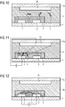
- Figs. 10 to 12 show the capture and translocation of a biopolymer using a further certain embodiment of the present setup as well as an exemplary method of the present invention with a different setup using an auxiliary electrode 2a, which in this case is applied on a surface 1a of a flow channel on an opposite side of the two main electrodes 2 in relation to the nanoporous network layer 3 inside the flow channel, here above the two main electrodes 2 and the nanoporous network layer 3.
- capturing is carried out again by applying an electrical field between the auxiliary electrode 2a and the left main electrode 2 so that the biopolymers 5 are caught in the nanoporous network layer 3 near the left electrode 2.
- a hydrophobic liquid 4a replaces the solvent 4, as shown in Fig. 12 .
- the translocation is shown again in Fig. 12 , similar to Fig. 9 , by applying an electric field between the main electrodes and switching off the electrical field shown in Fig. 11 .
- Figs. 13 and 14 show another setup and method according to the invention, which also represents the different steps shown in Figs. 11 and 12 in more detail.
- the biopolymers 5 are attracted to the main electrode 2 on the left by applying an electric field between the main electrode 2 on the left and the auxiliary electrode 2a into the nanoporous network layer 3.
- this setup provides three different resistances for the biopolymers 5, namely the resistance R E of the solvent 4, the resistance R C for capture inside the nanoporous network layer 3, and a resistance R T for translocation with R(E) ⁇ R(C) ⁇ R(T).
- R E is about the same or slightly higher than R C so that the capture is enhanced compared to the state of the art, and the electrical fields in the solvent 4 (E E ) and in the nanoporous network layer (E C ) are similar when a capture voltage V C is applied.
- the geometrical constellation in this figure thus provides an electrical resistance R C inside the nanoporous network layer between the at least one main electrode 2 on the left which functions as catcher electrode and the solvent 4 which is low enough to generate suitable electrical fields (E E of the solvent, e.g. electrolyte, E C of the catcher electrode) between the catcher electrode 2 and the auxiliary electrode 2a to move the biopolymer 5 from the solution into the nanoporous network layer 3.
- Fig. 14 depicts in more detail how the biopolymers 5 are elongated by applying the longitudinal voltage V l for translocating the biopolymers 5 through the nanoporous network layer 3, which represents a resistance R t , which is thus also the resistance that has to be overcome to translocate the biopolymers to e.g. tunneling electrodes for detection and sequencing.
- the hydrophobic liquid 4a represents a further resistance to the biopolymers 5 so that they do not leave the nanoporous network layer.
- the present invention therefore relates to a method of capturing at least one biopolymer, preferably at least one nucleic acid molecule, and its controlled translocation through a nanoporous network, comprising:
- a suitable voltage between at least two electrodes of the setup of the first aspect particularly with regard to the application of a suitable voltage between the at least two main electrodes to translocate the at least one biopolymer inside the nanoporous network layer, it should be noted that the applied voltage will depend on the nature of the biopolymer to be captured and translocated, further constituents of the solution or suspension containing the at least one biopolymer, e.g. a solvent, the material of the electrodes, etc.
- an upper limit of about 2 V for the applied voltage may be of advantage to avoid electrolysis of water, e.g. when metals like Pt or Au are used as electrode material or other materials that can lead to the development of radicals and a formation of gas due to water electrolysis.
- electrode materials like Cu or Ag/AgCl
- ions like Cu 2+ or Cl - can be formed, so that a formation of radicals and gases can be avoided when using water as a solvent, so that also higher voltages can be applied.
- the application of the voltage between at least two electrodes of the setup of the first aspect for a time sufficient to introduce the at least one biopolymer into the, e.g. continuous, nanoporous network layer can comprise, as shown above, the application of a voltage between at least two main electrodes, as e.g. shown in Figs. 4 to 6 , or the application of a voltage between at least one main electrode and at least one auxiliary electrode - if present, as e.g. shown in Figs. 7 to 9 , 10 to 12 , and 13 and 14 .
- the at least two electrodes for introducing the at least one biopolymer into the, e.g. continuous, nanoporous network layer can be thus the at least main two electrodes; or they can be represented by one of the two main electrodes and at least one, e.g. one, auxiliary electrode if it is contained.
- 3 or more electrodes can be involved for capturing.
- one negatively polarized auxiliary electrode and two positively polarized main electrodes may be used to capture the nucleic acids with both main electrodes, as also described above.
- translocation e.g. the two main electrodes are involved, keeping the captured nucleic acid above one electrode more or less stationary in a first translocation step. After inversion of the polarization, all nucleic acid molecules can be translocated into the opposite direction, e.g. to the other main electrode.
- a suitable voltage between the at least two main electrodes to translocate the at least one biopolymer inside the nanoporous network layer can be set according to the solvent used in the solution or suspension, the at least one biopolymer, the material of the nanoporous network layer and the pore sizes therein, etc., in order to provide a desired velocity for translocating the at least one biopolymer, e.g. for detection and or sequencing, e.g. through a pair of tunneling electrodes. It can be e.g. between about 0.001 and about 4 V, e.g. between about 0.005 and about 3 V, e.g. between about 0.008 and about 2.5 V, e.g. between about 0.01 V and about 2 V.
- the voltage for the translocation can be set lower than the voltage for capture of the at least one biopolymer.
- the present method in other words, comprises:
- the present setup and method allow the application of a sufficiently high catch voltage V c , e.g. between about 0.01 and about 4 V, e.g. between about 0.05 and about 3 V, e.g. between about 0.08 and about 2.5 V, e.g. between about 0.1 and about 2 V, to capture the target biopolymers from the solution or suspension, e.g. electrolyte solution, in a considerable short time even when the concentration is very low.
- V c sufficiently high catch voltage
- V c sufficiently high catch voltage
- the biopolymer for example a nucleic acid molecule, e.g. folded single stranded DNA or RNA
- the setup during the capturing process can be adjusted to keep the electrical field inside the solvent of the solution or suspension, e.g. an electrolyte, similar to the electrical field inside the nanoporous network layer.
- This can be e.g. adjusted by a suitable ratio of electrolyte thickness, e.g. inside the flow channel, versus nanoporous layer thickness and the area of the catcher electrode.
- the thickness of the nanoporous layer is not particularly restricted and can be e.g. between 5 nm and 5 ⁇ m, e.g.
- between 8 nm and 2 ⁇ m e.g. between 10 nm and 1 ⁇ m, e.g. between 20 nm and 500 nm, e.g. between 50 nm and 200 nm, and can be e.g. about 100 nm.
- the area thereof is not particularly restricted as well and can be e.g. between 0.1 and 1000 ⁇ m 2 , e.g. between 0.5 and 500 ⁇ m 2 , e.g. between 1 to 100 ⁇ m 2 , e.g. between 2 and 50 ⁇ m 2 , e.g. between 5 and 20 ⁇ m 2 , and can be e.g. about 10 ⁇ m 2 .
- the voltage V l can be chosen sufficiently low e.g. between about 0.001 and about 4 V, e.g. between about 0.005 and about 3 V, e.g. between about 0.008 and about 2.5 V, e.g. between about 0.01 V and about 2 V, in the present method.
- the solution or suspension containing the at least one biopolymer is not particularly restricted and can contain, apart from the at least one biopolymer, e.g. at least one nucleic acid molecule, and at least one solvent, e.g. water or a mixture of water with a further solvent or a non-aqueous solvent or a mixture of non-aqueous solvents, further components that are not particularly restricted, e.g. one or more electrolytes which are not particularly restricted and which can support the biopolymer capture and translocation, one or more buffers, and/or substances which can manipulate the at least one biopolymer, e.g. which support the formation of single stranded nucleic acid, such as formamide, etc.
- solvent e.g. water or a mixture of water with a further solvent or a non-aqueous solvent or a mixture of non-aqueous solvents
- further components that are not particularly restricted, e.g. one or more electrolytes which are not particularly restricted and which can support the biopol
- the solution or suspension can be composed to provide a dedicated, typically low ionic-strength to optimize the electrophoretic transport of the biopolymer, e.g. by introduction of zwitterion-buffers, such as histidine, and/or a dedicated pH to stabilize the at least one biopolymer, e.g. nucleic acid or protein.
- the solution or suspension can be of natural or artificial origin and can comprise e.g. a patient sample or a solution or suspension derived from a patient sample, e.g. a solution or suspension that is worked up from a patient sample and/or where further components, e.g. electrolytes and/or buffers, are added.
- a non-aqueous solvent is not particularly restricted and can be e.g. an alcohol, e.g. ethanol, propanol, phenol, glycol, etc., an ester, etc.
- a solvent for the solution or suspension containing the at least one biopolymer is water.
- sample is a sample containing at least one biopolymer to be captured and translocated, e.g. at least a nucleic acid molecule.
- the sample is not particularly restricted and can be of natural or synthetic origin and can e.g. comprise samples from simple or complex matrices, e.g. from a subject, e.g. a vertebrate, e.g. a human or animal, or from a natural source, e.g. an extract from soil, air, or a natural water/water body.
- the sample can also be water-free or water-poor, e.g. when it contains a non-aqueous solvent.
- the sample can comprise nucleic acid molecules, and the method is used to provide extracted, cleaned nucleic acid (e.g. DNA), particularly in a solvent of low ionic strength, e.g. a Histidine buffer of e.g. 10 mM, e.g. with an additive like formamide to stabilize ssDNA (single strand DNA).
- a solvent of low ionic strength e.g. a Histidine buffer of e.g. 10 mM, e.g. with an additive like formamide to stabilize ssDNA (single strand DNA).
- the at least one biopolymer e.g. nucleic acid
- the captured beads with the at least one biopolymer then can be washed with a suitable solvent, and then the solvent can be exchanged with a suitable compound or compound mixture to further prepare the biopolymer for capture.
- a solvent like water for washing can be exchanged with a low ionic-strength, histidine and formamide containing buffer in case DNA is the at least one biopolymer to be captured.
- nucleic acid as a biopolymer can be deliberated from the magnetic beads, denatured by formamide and finally captured into the nanoporous layer by the present, electrophoretic, capturing process.
- the magnetic beads can e.g. remain when the hydrophobic liquid is introduced as they should not interfere with the translocation, or can be washed out before the translocation.
- the volume to be handled in the present method can be reduced, so that the method can be carried out more efficient.
- the sample is an aqueous sample, i.e. a sample containing water.
- the sample can be a body fluid of a subject.
- Body fluids are thereby liquids originating from inside the bodies of subjects, particularly living subjects. They include fluids that can be excreted or secreted from the body and/or that circulate in the body, and body water. They can be in the state of a liquid, emulsion or suspension.
- body fluids within the invention are blood, urine, saliva, sputum, plasma, serum, etc.
- the sample is a patient sample (clinical isolate). Exemplified samples are serum, plasma, and/or whole blood of a patient.
- the subject in the present method of extracting a substance from a sample, enriching a substance in a sample and/or detecting a substance in a sample can be a vertebrate, preferably a human or animal, more preferably a mammal and most preferred a human, respectively human patient.
- a vertebrate within the present invention refers to animals having a vertebrate, which includes mammals - including humans, birds, reptiles, amphibians and fishes.
- the present invention thus is not only suitable for humans and the human medical field, but also for veterinary medicine.
- the hydrophobic liquid is an oil, e.g. a mineral oil and/or a silicon oil.
- the mineral oil and the silicon oil are therein not particularly restricted.
- the mineral oil and or silicon oil can hinder the biopolymer(s) from leaving the nanoporous network layer and restricts the electrical translocation field within the nanoporous layer so that the translocation of the biopolymer(s) through the nanoporous network layer is enhanced, thereby providing for a good linearization of the biopolymer(s), i.e. for stretching the at least one biopolymer from e.g. a ball-like or irregular shaped form into a linear form.
- the translocation therein does not necessarily have to result of a translocation of the whole biopolymer at the same time and can e.g. also relate to a translocation of only a part thereof, e.g. one end thereof, in a certain direction, followed by a translocation of further parts thereof at a later time. It is also not necessary during translocation that the whole biopolymer is brought into linear form as long as the biopolymer can be translocated to a certain goal, e.g. a pair of tunneling electrodes, so that it then can pass there through with a defined direction.
- a certain goal e.g. a pair of tunneling electrodes
- the replacement of the solvent of the solution or suspension, e.g. an electrolyte by a hydrophobic liquid, e.g. oil further can avoid an electrical short-circuit during translocation as well as a bypassing of biopolymers of a tunneling electrode junction.
- a third aspect of the present invention is directed to a pre-subarray, comprising a multitude of setups of the invention, i.e. of the first aspect, and at least one readout-circuit.
- a multitude of setups therein can include 2, 3, 4, 5, 6, 7, 8, 9, 10, 11, 12, 13, 14, 15, 16 or more setups, which can all be also on one solid substrate, i.e. include a setup with one solid substrate on which the electrodes - main and optionally auxiliary electrodes - and nanoporous network layers are combined. It is also not excluded that the multitude of flow channels that can be formed in such a subarray can form one flow channel itself, e.g. by connecting a multitude of flow channels. Also the nanoporous network layers can be interconnected, e.g. for an ease of manufacturing.
- the readout-circuit in the pre-subarray is not particularly restricted and can be configured to connect suitably the electrodes provided. It can also connect additional vias which can be present and or further electrode bases and/or electrodes, e.g. for forming tunneling electrodes and/or reference electrodes.
- additional vias can be present and or further electrode bases and/or electrodes, e.g. for forming tunneling electrodes and/or reference electrodes.
- a detector for detecting tunneling currents on a pair or multiple pairs of tunneling electrodes to be formed can already be provided in the present pre-subarray according to certain embodiments, which is not particularly restricted and which can comprise those known in the state of the art, e.g. from WO 2014048816 A1 and WO 2015010904 A1 .
- the multitude of setups is preferably located on one substrate, in which e.g. the at least one readout-circuit can be integrated.
- a pre-array comprising a multitude of pre-subarrays of the third aspect.
- a multitude of pre-subarrays therein can include 2, 3, 4, 5, 6, 7, 8, 9, 10, 11, 12, 13, 14, 15, 16 or more pre-subarrays, which can all be also on one solid substrate, i.e. include a setup with one solid substrate on which the electrodes - main and optionally auxiliary electrodes - and nanoporous network layers are combined. It is also again not excluded that the multitude of flow channels that can be formed in such an array can form one flow channel itself, e.g. by connecting a multitude of flow channels. Also the nanoporous network layers can be interconnected as well, e.g. for an ease of manufacturing.
- the readout-circuits in the pre-arrays - as in the pre-subarrays - can be interconnected and can be configured to connect suitably the electrodes provided, forming again one readout-circuit.
- the readout-circuit(s) can also again connect additional vias which can be present and or further electrode bases and/or electrodes, e.g. for forming tunneling electrodes and/or reference electrodes.
- additional vias can be present and or further electrode bases and/or electrodes, e.g. for forming tunneling electrodes and/or reference electrodes.
- it is possible to form an array from the present pre-array by e.g. forming pairs of tunneling electrodes on the substrate, e.g. on vias and optionally electrode bases that are already formed in the pre-arrays. Therefore it is also possible to provide a pre-array on which then pairs of tunneling electrodes are formed in a later step, e.g. at a customer's site.
- a detector for detecting tunneling currents on a pair or multiple pairs of tunneling electrodes to be formed can already be provided in the present pre-array according to certain embodiments, which is not particularly restricted and which can comprise those known in the state of the art, e.g. from WO 2014048816 A1 and WO 2015010904 A1 .
- the present setups, pre-subarrays and/or pre-arrays can form a kit together with a component for forming the tunneling electrodes - e.g. a solution or suspension containing material for forming the tunneling electrodes, e.g. at a customer's site, by e.g. application of a suitable voltage to vias configured for contacting tunneling electrodes.
- a component for forming the tunneling electrodes e.g. a solution or suspension containing material for forming the tunneling electrodes, e.g. at a customer's site, by e.g. application of a suitable voltage to vias configured for contacting tunneling electrodes.
- a fifth aspect of the present invention relates to a device for sequencing at least one biopolymer, comprising the setup of the first aspect; a pair of tunneling electrodes; and a detector for detecting a tunneling current through the pair of tunneling electrodes.
- the pair of tunneling electrodes is not particularly restricted and can be made of any suitable material, e.g. a metal like Au, Pt, Ag, electrically conducting polymers, etc.
- the pair of tunneling electrodes can be formed at a location suitable for sequencing the at least one biopolymer, i.e. a location to which the at least one biopolymer is moved, e.g. between the at least two main electrodes.
- Fig. 15 An exemplary embodiment thereof is shown in Fig. 15 , where the setup comprises an (optional) auxiliary electrode 2a.
- the auxiliary electrode 2a is located in the same plane as the main electrodes and the tunneling electrodes 6.
- the pair of main electrodes that is connected by the source providing the longitudinal voltage V l .
- a capture voltage V C can be applied between the auxiliary electrode 2a and the left main electrode.
- the setup in the device shown in Fig. 15 is thus similar to the one in Fig. 7 .
- the exemplary device in Fig. 15 shows a pair of tunneling electrodes 6, represented by arrows, between which a tunneling voltage V t can be applied for detecting and sequencing the at least one biopolymer, e.g. a nucleic acid molecule, using the tunneling voltage according to the methods known to the skilled person.
- the nanoporous network layer is excluded for better visibility of the different circuits for applying a voltage.
- Figs. 1 and 15 show the basic transverse tunneling concept as well as the corresponding planar setup without the nanoporous network layer.
- the catcher-voltage V C and the longitudinal voltage V l are applied one after each other, thus leading to the improved method of the present invention using the present improved setup.
- the pair of tunneling electrodes can be provided at least partially in the nanoporous network layer so that the nanopores can provide a further restriction for passing the biopolymers through a gap between the tunneling electrodes. This is shown in more detail in Figs. 16 and 17 .
- Figs. 16 and 17 show the planar setup of Fig. 15 together with the nanoporous network layer 3, which is particularly visible in Fig. 16 on top of the main electrodes 2. Also a cross-section of the tunneling junction in the setup of Fig. 16 in the direction of the arrow depicted therein, perpendicular to the translocation direction, is shown in Fig. 17 . The formation and composition of such a cross-section can also be taken from WO 2015010904 A1 . In Fig. 17 especially the base electrodes 6b on which the tunneling electrodes 6 are formed, as well as the gap 6a between the tunneling electrodes, which can also be filled with nanoparticles 3a or similar structures of the nanoporous network layer 3, can be seen.
- Fig. 17 it is also depicted how the hydrophobic liquid 4a which replaces solvent 4 is present on top of the tunneling electrodes 6.
- the hydrophobic liquid can ensure that the biopolymers are not going over and/or around the tunneling electrodes and are actually passing there through, enabling the sequencing of these biopolymers. Also the junction-cross-section of the tunneling electrodes can be restricted this way.
- the solid substrate and/or the nanoporous network layer as e.g. also described later in connection with Figs. 2 , 23 , 25 , 29 and 30 , where e.g. the solid substrate and/or the nanoporous network layer is narrowed down in width next to the tunneling electrodes, e.g. essentially to the width of the tunneling electrodes, it can be further ensured that the at least one biopolymer passes through the tunneling electrode junction by application of the hydrophobic liquid, as the hydrophobic liquid can cover the whole tunneling electrodes and thus ensure that no biopolymer can go around them.
- a sixth aspect of the present invention relates to a sub-array for sequencing at least one biopolymer, comprising the pre-subarray of the third aspect; a multitude of pairs of tunneling electrodes, wherein for each setup of the first aspect a pair of tunneling electrodes is provided; and a detector for detecting tunneling currents through the multitude of pairs of tunneling electrodes.
- the tunneling electrodes can be configured the same way as in the present device, so that the corresponding descriptions also apply to the subarray.
- the detector can be the same as in the present device.
- translocation electrodes e.g. the two main electrodes, and the pair of tunneling electrodes provided to these translocation electrodes, in a setup can be separately connected to the detector with a single detector circuit, so that in a sub-array just one setup for detection can be selected, e.g. the one with the best efficiency.
- these detectors of a sub-array can then be read out using multiplexing, e.g. in parallel, so that a multitude of sub-arrays can be processed simultaneously.
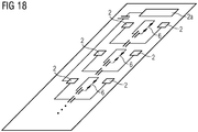
- Fig. 18 shows the schematic arrangement of multiple capture / translocation / tunneling units with multiple main electrodes 2 wherein for each pair one acts as catcher electrode, and multiple tunneling electrode pairs 6 in an exemplary subarray, herein supplied by one auxiliary electrode 2a to capture the target biopolymers, e.g. from a larger electrolyte reservoir above the chip over several of the main electrode 2 locations.
- the tunneling electrodes can then be connected to one detector that is not shown.
- the readout-circuits are not shown.
- more than 3 devices, as indicated above, can be present in a sub-array.
- auxiliary electrode In this special subarray it is possible that all setup "units" are supplied by one auxiliary electrode to transport target biopolymer molecules to the catcher electrodes of each unit.
- the auxiliary electrode can have various different geometries, such as a "bus-structure” around, or a network structure within the array-positions.
- a seventh aspect of the present invention is directed to an array, comprising a multitude of sub-arrays of the sixth aspect, or comprising a pre-array of the fourth aspect; a multitude of pairs of tunneling electrodes, wherein for each setup of the first aspect a pair of tunneling electrodes is provided; and at least one detector for detecting tunneling currents through the multitude of pairs of tunneling electrodes.
- the tunneling electrodes can be configured the same way as in the present device, so that the corresponding descriptions also apply to the subarray.
- the detector can be the same as in the present device.
- a multitude of detectors with a multitude of circuits, each e.g. provided for one subarray can be read out, e.g. in parallel or sequentially, preferably in parallel.
- At least one selection switch is contained in the readout-circuit for each pair of tunneling electrodes provided for each setup in a device, subarray, or array of the invention for a connection to one detector.
- Fig. 19 therein shows a cross section of a setup wherein vias 6b are inside the upper layer of a substrate, with a CMOS-metal-layer below the vias 6b for contacting.
- each two main electrodes 2 can be formed, as shown in Fig. 20 , e.g. by a metallization, to form a setup as in Fig. 4 (with the nanoporpous network layer not shown, which can be added after formation of the main electrodes).
- the surface of the solid substrate is not planar as the main electrodes 2 are above the surface, which may lead to a disturbance in the capture and/or translocation due to possible inhomogeneities in the nanoporous network layer.
- the vias 7 itself can be used as main electrode, thus forming a kind of "virtual electrode surface" over the vias, which can be e.g. comprise also a field similar to the electrode surface indicated in Fig. 20 , thus also forming a "main electrode” 2.
- this alternative setup is further used. This setup can be easily processed to produce an essentially flat surface on the solid substrate including the vias 7 as electrodes, e.g. by a polishing process like chemical-mechanical polishing (CMP) .
- CMP chemical-mechanical polishing
- Fig. 21 shows the vias 6b with the applied nanoporous layer 3 in a cross section indicated in Fig. 22, and Fig. 22 shows the final formation of the nanoporous network layer 3 also over the "virtual surface" of the main electrodes 2, formed by the four vias 7, as indicated in Fig. 20 , and over the vias 6b in a shape that narrows near the vias 6b so that the tunneling electrodes will pass beyond the nanoporous network layer 3 upon formation.
- the nanoporous network layer can be formed with a thickness of about 100 nm, and can have Au-nanobeads embedded therein for better contacting.
- the main electrodes can be formed e.g. of Pt, Au, W or Cu.
- the electrode surfaces can be planarized by chemical mechanical polishing, e.g. also together with the top substrate layer, e.g. an insulating layer made of e.g. SiO 2 and/or Si 3 N 4 before application of the nanoporous network layer.
- the nanoporous network layer can be e.g. applied by spin-coating of a sol-gel layer, e.g. formed with a metal alcoholate, to which conductive particles, e.g. Au-beads with a diameter of about 5 nm, can be added. After tempering a nanoporous network layer with pores of about 1 to 5 nm size and a thickness of about 100 nm can be formed, which can be structured as shown in Fig. 22 using known semiconductor-technological processes, e.g. with a resist mask and etching.
- Fig. 23 shows how a present setup 10 with two main electrodes 2 and two vias 6b for tunneling electrodes - on which the tunneling electrodes 6 can be formed as indicated by the circular dashed lines - with a nanoporous network layer formed in a similar fashion as in Example 1 (dashed line around the main electrodes 2 and vias 6b) can be integrated into a pre-subarray 100 comprising a number of setups and one readout-circuit, and how the pre-subarray 100 can be integrated into a pre-array 1000.
- a further reference electrode is shown (no numbering), which is not essential but can be used for reference.
- the number of setups 10, respectively pre-subarrays 100, used therein is not limited.
- pre-subarrays and pre-arrays respectively subarrays and arrays
- the tunneling electrodes in a device, subarray or array of the invention can be formed at a later point, e.g. at a customer's site.
- Figs. 24 and 25 show an exemplary present device.
- Fig. 24 shows a cross-section thereof, similar to the one in Example 1, with the vias 6b contacting the the pair of tunneling electrodes 6 formed on the substrate and the nanoporous network layer 3.
- biopolymers here negatively charged nucleic acid molecules
- the main electrode on the left is applied as positive electrode in the nanoporous network layer, which has a shape as in Example 1.
- the biopolymers e.g. DNA
- the biopolymers e.g. DNA
- Figs. 26 and 27 show the capture of exemplary biopolymers 5, e.g. DNA, in a setup as shown in Figs. 13 and 14 .
- the biopolymers 5 present in a buffer 8, e.g. a histidine buffer at a pH of 7 - 8, with low ionic strength, for example DNA, can be introduced into the nanoporous network layer, herein exemplified by nanoparticles 3a for better visibility, by applying a suitable voltage between an auxiliary electrode at the top, e.g. made of Ag/AgCl, Pt and/or Au, and a main electrode 2 on the bottom, being made of e.g. Pt and/or Au ( Fig. 26 , Ex. 4), or Cu ( Fig. 27 , Ex. 5). Also possible reactions at the electrodes are shown, e.g. the complexation of Cu 2+ ions by the histidine buffer at the positive electrode.
- Figs. 28 to 30 it is shown how biopolymers cannot bypass the device of Example 3 after application of a hydrophobic liquid 4a, e.g. an oil like mineral oil, when the biopolymer are captured inside the nanoporous network layer, with Fig. 28 again showing the cross-section in Fig. 29, and Fig. 29 the top-view with the tunneling electrodes 6 shown in more detail.
- a hydrophobic liquid 4a e.g. an oil like mineral oil
- Figs. 31 to 34 show in detail a translocation of biopolymers through a device as shown in Examples 3 and 6.
- the hydrophobic liquid 4a is applied, so that the captured biopolymers cannot leave the nanoporous network layer 3.
- the biopolymers 5, e.g. here nucleic acid molecules having a negative charge like DNA are moved through the nanoporous network layer 3 towards the tunneling electrodes 6 by applying a negative potential on the main electrode on the left and a positive potential on the main electrode on the right.
- the biopolymers then can pass through a gap 6a between the tunneling electrodes 6, shown in more detail in Figs.
- the tunneling electrodes can e.g. have an uneven surface after a deposition, e.g. a galvanical deposition of a noble metal like Au. As shown in Fig.
- a pore between the tunneling electrodes can have suitable conditions for tunneling-based sequencing when a short electrode junction is formed at least at one position and/or when the structure of the nanoporous network layer at the tunneling electrodes aids in the sequencing by further minimizing the pore, as e.g. described in WO 2014048816 A1 and WO 2015010904 A1 .
- Figs. 35 (Ex. 8) and 36 (Ex. 9) the translocation of the exemplary biopolymer, DNA, in Examples 4 and 5, respectively, through the nanoporous network layer is shown after applying the respective voltage to the main electrodes, similar to the voltages in Example 7.
- the DNA is elongated through the nanoporous network layer, so that it can be sequenced easily at the tunneling electrodes (not shown).
- the polarization can be altered to move the biopolymer, e.g. DNA, back and forth through the tunneling electrodes, respectively nanoporous network layer.
- reactions at the electrodes are shown again, e.g. the complexation of Cu 2+ ions by the histidine buffer at the positive electrode.
- a setup- and method-based separation of the capturing and the translocation of an analyte biopolymer can be achieved, allowing the application of dedicated voltages, e.g. high for catch and/or low for translocation.
Priority Applications (1)
| Application Number | Priority Date | Filing Date | Title |
|---|---|---|---|
| EP17191863.4A EP3456414A1 (fr) | 2017-09-19 | 2017-09-19 | Configuration et procédé de capture d'un biopolymère et sa translocation commandée par l'intermédiaire d'un réseau nanoporeux |
Applications Claiming Priority (1)
| Application Number | Priority Date | Filing Date | Title |
|---|---|---|---|
| EP17191863.4A EP3456414A1 (fr) | 2017-09-19 | 2017-09-19 | Configuration et procédé de capture d'un biopolymère et sa translocation commandée par l'intermédiaire d'un réseau nanoporeux |
Publications (1)
| Publication Number | Publication Date |
|---|---|
| EP3456414A1 true EP3456414A1 (fr) | 2019-03-20 |
Family
ID=59982252
Family Applications (1)
| Application Number | Title | Priority Date | Filing Date |
|---|---|---|---|
| EP17191863.4A Withdrawn EP3456414A1 (fr) | 2017-09-19 | 2017-09-19 | Configuration et procédé de capture d'un biopolymère et sa translocation commandée par l'intermédiaire d'un réseau nanoporeux |
Country Status (1)
| Country | Link |
|---|---|
| EP (1) | EP3456414A1 (fr) |
Cited By (1)
| Publication number | Priority date | Publication date | Assignee | Title |
|---|---|---|---|---|
| WO2021206728A1 (fr) * | 2020-04-10 | 2021-10-14 | Hewlett-Packard Development Company, L.P. | Dispositifs microfluidiques de détection de nanopores |
Citations (3)
| Publication number | Priority date | Publication date | Assignee | Title |
|---|---|---|---|---|
| US6627067B1 (en) | 1999-06-22 | 2003-09-30 | President And Fellows Of Harvard College | Molecular and atomic scale evaluation of biopolymers |
| WO2014048816A1 (fr) | 2012-09-27 | 2014-04-03 | Siemens Aktiengesellschaft | Système pour le séquençage d'acides nucléiques par analyse par courant tunnel |
| WO2015010904A1 (fr) | 2013-07-23 | 2015-01-29 | Siemens Aktiengesellschaft | Procédé de production d'un nanopore pour le séquençage d'un biopolymère |
-
2017
- 2017-09-19 EP EP17191863.4A patent/EP3456414A1/fr not_active Withdrawn
Patent Citations (5)
| Publication number | Priority date | Publication date | Assignee | Title |
|---|---|---|---|---|
| US6627067B1 (en) | 1999-06-22 | 2003-09-30 | President And Fellows Of Harvard College | Molecular and atomic scale evaluation of biopolymers |
| WO2014048816A1 (fr) | 2012-09-27 | 2014-04-03 | Siemens Aktiengesellschaft | Système pour le séquençage d'acides nucléiques par analyse par courant tunnel |
| US20150268220A1 (en) * | 2012-09-27 | 2015-09-24 | Siemens Aktiengesellschaft | Assembly for nucleic acid sequencing by means of tunnel current analysis |
| WO2015010904A1 (fr) | 2013-07-23 | 2015-01-29 | Siemens Aktiengesellschaft | Procédé de production d'un nanopore pour le séquençage d'un biopolymère |
| US20160153105A1 (en) * | 2013-07-23 | 2016-06-02 | Siemens Aktiengesellschaft | Producing a nanopore for sequencing a biopolymer |
Non-Patent Citations (8)
| Title |
|---|
| ALLISON H. SQUIRES ET AL: "A Nanopore-Nanofiber Mesh Biosensor To Control DNA Translocation", JOURNAL OF THE AMERICAN CHEMICAL SOCIETY, vol. 135, no. 44, 24 October 2013 (2013-10-24), US, pages 16304 - 16307, XP055436229, ISSN: 0002-7863, DOI: 10.1021/ja408685x * |
| DI VENTRA M.: "Fast DNA sequencing by electrical means inches closer", NANOTECHNOLOGY, vol. 24, 2013, pages 342501, XP020249248, DOI: doi:10.1088/0957-4484/24/34/342501 |
| G. M. ARIFUZZAMAN KHAN ET AL: "Graft Polycondensation of Microfibrillated Jute Cellulose with Oligo(L-lactic acid) and its properties", JOURNAL OF APPLIED POLYMER SCIENCE, vol. 131, no. 8, 16 November 2013 (2013-11-16), pages n/a - n/a, XP055098748, ISSN: 0021-8995, DOI: 10.1002/app.40139 * |
| LAFLEUR JOSIANE P ET AL: "Recent advances in lab-on-a-chip for biosensing applications", BIOSENSORS AND BIOELECTRONICS, ELSEVIER BV, NL, vol. 76, 13 August 2015 (2015-08-13), pages 213 - 233, XP029300781, ISSN: 0956-5663, DOI: 10.1016/J.BIOS.2015.08.003 * |
| LI JI ET AL: "Solid-state nanopore-based DNA single molecule detection and sequencing", MIKROCHIMICA ACTA, SPRINGER VERLAG, VIENNA, AT, vol. 183, no. 3, 5 September 2015 (2015-09-05), pages 941 - 953, XP035887513, ISSN: 0026-3672, [retrieved on 20150905], DOI: 10.1007/S00604-015-1542-4 * |
| MD. AZAHAR ALI ET AL: "A surface functionalized nanoporous titania integrated microfluidic biochip", NANOSCALE, vol. 6, no. 22, 1 January 2014 (2014-01-01), United Kingdom, pages 13958 - 13969, XP055436241, ISSN: 2040-3364, DOI: 10.1039/C4NR03791J * |
| OHSHIRO T; MATSUBARA K; TSUTSUI M; FURUHASHI M; TANIGUCHI M ET AL.: "Single-molecule electrical random resequencing of DNA and RNA", SCI REP, vol. 2, 2012, pages 501 |
| PALLAVI DAGGUMATI ET AL: "Effect of Nanoporous Gold Thin Film Morphology on Electrochemical DNA Sensing", ANALYTICAL CHEMISTRY, vol. 87, no. 16, 18 August 2015 (2015-08-18), US, pages 8149 - 8156, XP055436233, ISSN: 0003-2700, DOI: 10.1021/acs.analchem.5b00846 * |
Cited By (1)
| Publication number | Priority date | Publication date | Assignee | Title |
|---|---|---|---|---|
| WO2021206728A1 (fr) * | 2020-04-10 | 2021-10-14 | Hewlett-Packard Development Company, L.P. | Dispositifs microfluidiques de détection de nanopores |
Similar Documents
| Publication | Publication Date | Title |
|---|---|---|
| US11898984B2 (en) | Nanopore arrays for sequencing nucleic acids | |
| Gu et al. | Single molecule sensing by nanopores and nanopore devices | |
| US10316360B2 (en) | Methods for creating bilayers for use with nanopore sensors | |
| US6955670B2 (en) | Nanopump system | |
| US7799197B2 (en) | Nanopump devices and methods | |
| CN103353476B (zh) | 分离并离析细胞、囊泡、纳米颗粒和生物标记的离体多维系统 | |
| US10145846B2 (en) | Digital protein sensing chip and methods for detection of low concentrations of molecules | |
| TWI596327B (zh) | 有興趣之生物物質的收集與濃縮系統及其應用 | |
| CN106796214B (zh) | 混合纳米孔传感器 | |
| US20150219618A1 (en) | Manipulation of microparticles in low field dielectrophoretic regions | |
| US7641780B2 (en) | Two-dimensional microfluidics for protein separations and gene analysis | |
| KR20000068494A (ko) | 생물 샘플의 능동적 제조를 위한 장치 및 방법 | |
| US20070048745A1 (en) | Systems and methods for partitioned nanopore analysis of polymers | |
| JP2021509265A (ja) | 生体サンプルからの複数の分析物の検出のための方法およびデバイス | |
| KR20210138594A (ko) | 나노포어 감지 디바이스 및 이를 작동하는 방법 및 형성하는 방법 | |
| KR20140015420A (ko) | 세포 조작용 나노피펫 장치 | |
| KR20150083722A (ko) | 모세관을 이용한 단백질 농축 소자 및 그 제조 방법 | |
| US7465381B2 (en) | Electrokinetic molecular separation in nanoscale fluidic channels | |
| WO2017039080A1 (fr) | Appareil de concentration d'échantillon et procédé d'extraction d'échantillon concentré l'utilisant | |
| US20180230531A1 (en) | Apparatus and methods for continuous diagnostics of macromolecules | |
| EP3456414A1 (fr) | Configuration et procédé de capture d'un biopolymère et sa translocation commandée par l'intermédiaire d'un réseau nanoporeux | |
| KR101577523B1 (ko) | 마이크로 유체 기반 표면전하 제어형 단백질 농축 소자 및 그 제조 방법 | |
| CN113711022B (zh) | 生物体聚合物分析设备、分析装置以及分析方法 | |
| US20170016877A1 (en) | Apparatus and method for electrical detection of oligonucleotides through pore blockades | |
| KR100731913B1 (ko) | 생체분자 검출용 나노하이브리드 입자의 제조방법, 나노하이브리드 입자를 이용한 생체분자 검출기, 생체분자 검출 방법 및 생체분자 검출용 분석장치 |
Legal Events
| Date | Code | Title | Description |
|---|---|---|---|
| PUAI | Public reference made under article 153(3) epc to a published international application that has entered the european phase |
Free format text: ORIGINAL CODE: 0009012 |
|
| AK | Designated contracting states |
Kind code of ref document: A1 Designated state(s): AL AT BE BG CH CY CZ DE DK EE ES FI FR GB GR HR HU IE IS IT LI LT LU LV MC MK MT NL NO PL PT RO RS SE SI SK SM TR |
|
| AX | Request for extension of the european patent |
Extension state: BA ME |
|
| STAA | Information on the status of an ep patent application or granted ep patent |
Free format text: STATUS: THE APPLICATION IS DEEMED TO BE WITHDRAWN |
|
| 18D | Application deemed to be withdrawn |
Effective date: 20190921 |