EP3456403B1 - Gastrennungsverfahren - Google Patents
Gastrennungsverfahren Download PDFInfo
- Publication number
- EP3456403B1 EP3456403B1 EP18194411.7A EP18194411A EP3456403B1 EP 3456403 B1 EP3456403 B1 EP 3456403B1 EP 18194411 A EP18194411 A EP 18194411A EP 3456403 B1 EP3456403 B1 EP 3456403B1
- Authority
- EP
- European Patent Office
- Prior art keywords
- gas
- separation membrane
- gas separation
- membrane module
- pressure
- Prior art date
- Legal status (The legal status is an assumption and is not a legal conclusion. Google has not performed a legal analysis and makes no representation as to the accuracy of the status listed.)
- Not-in-force
Links
Images


Classifications
-
- B—PERFORMING OPERATIONS; TRANSPORTING
- B01—PHYSICAL OR CHEMICAL PROCESSES OR APPARATUS IN GENERAL
- B01D—SEPARATION
- B01D53/00—Separation of gases or vapours; Recovering vapours of volatile solvents from gases; Chemical or biological purification of waste gases, e.g. engine exhaust gases, smoke, fumes, flue gases, aerosols
- B01D53/22—Separation of gases or vapours; Recovering vapours of volatile solvents from gases; Chemical or biological purification of waste gases, e.g. engine exhaust gases, smoke, fumes, flue gases, aerosols by diffusion
- B01D53/228—Separation of gases or vapours; Recovering vapours of volatile solvents from gases; Chemical or biological purification of waste gases, e.g. engine exhaust gases, smoke, fumes, flue gases, aerosols by diffusion characterised by specific membranes
-
- B—PERFORMING OPERATIONS; TRANSPORTING
- B01—PHYSICAL OR CHEMICAL PROCESSES OR APPARATUS IN GENERAL
- B01D—SEPARATION
- B01D53/00—Separation of gases or vapours; Recovering vapours of volatile solvents from gases; Chemical or biological purification of waste gases, e.g. engine exhaust gases, smoke, fumes, flue gases, aerosols
- B01D53/22—Separation of gases or vapours; Recovering vapours of volatile solvents from gases; Chemical or biological purification of waste gases, e.g. engine exhaust gases, smoke, fumes, flue gases, aerosols by diffusion
-
- B—PERFORMING OPERATIONS; TRANSPORTING
- B01—PHYSICAL OR CHEMICAL PROCESSES OR APPARATUS IN GENERAL
- B01D—SEPARATION
- B01D63/00—Apparatus in general for separation processes using semi-permeable membranes
- B01D63/10—Spiral-wound membrane modules
- B01D63/107—Specific properties of the central tube or the permeate channel
-
- B—PERFORMING OPERATIONS; TRANSPORTING
- B01—PHYSICAL OR CHEMICAL PROCESSES OR APPARATUS IN GENERAL
- B01D—SEPARATION
- B01D69/00—Semi-permeable membranes for separation processes or apparatus characterised by their form, structure or properties; Manufacturing processes specially adapted therefor
- B01D69/02—Semi-permeable membranes for separation processes or apparatus characterised by their form, structure or properties; Manufacturing processes specially adapted therefor characterised by their properties
-
- B—PERFORMING OPERATIONS; TRANSPORTING
- B01—PHYSICAL OR CHEMICAL PROCESSES OR APPARATUS IN GENERAL
- B01D—SEPARATION
- B01D69/00—Semi-permeable membranes for separation processes or apparatus characterised by their form, structure or properties; Manufacturing processes specially adapted therefor
- B01D69/04—Tubular membranes
-
- B—PERFORMING OPERATIONS; TRANSPORTING
- B01—PHYSICAL OR CHEMICAL PROCESSES OR APPARATUS IN GENERAL
- B01D—SEPARATION
- B01D69/00—Semi-permeable membranes for separation processes or apparatus characterised by their form, structure or properties; Manufacturing processes specially adapted therefor
- B01D69/12—Composite membranes; Ultra-thin membranes
- B01D69/1216—Three or more layers
-
- B—PERFORMING OPERATIONS; TRANSPORTING
- B01—PHYSICAL OR CHEMICAL PROCESSES OR APPARATUS IN GENERAL
- B01D—SEPARATION
- B01D69/00—Semi-permeable membranes for separation processes or apparatus characterised by their form, structure or properties; Manufacturing processes specially adapted therefor
- B01D69/14—Dynamic membranes
- B01D69/141—Heterogeneous membranes, e.g. containing dispersed material; Mixed matrix membranes
- B01D69/142—Heterogeneous membranes, e.g. containing dispersed material; Mixed matrix membranes with "carriers"
-
- B—PERFORMING OPERATIONS; TRANSPORTING
- B01—PHYSICAL OR CHEMICAL PROCESSES OR APPARATUS IN GENERAL
- B01D—SEPARATION
- B01D71/00—Semi-permeable membranes for separation processes or apparatus characterised by the material; Manufacturing processes specially adapted therefor
- B01D71/06—Organic material
- B01D71/38—Polyalkenylalcohols; Polyalkenylesters; Polyalkenylethers; Polyalkenylaldehydes; Polyalkenylketones; Polyalkenylacetals; Polyalkenylketals
- B01D71/381—Polyvinylalcohol
-
- B—PERFORMING OPERATIONS; TRANSPORTING
- B01—PHYSICAL OR CHEMICAL PROCESSES OR APPARATUS IN GENERAL
- B01D—SEPARATION
- B01D71/00—Semi-permeable membranes for separation processes or apparatus characterised by the material; Manufacturing processes specially adapted therefor
- B01D71/06—Organic material
- B01D71/40—Polymers of unsaturated acids or derivatives thereof, e.g. salts, amides, imides, nitriles, anhydrides, esters
- B01D71/401—Polymers based on the polymerisation of acrylic acid, e.g. polyacrylate
-
- B—PERFORMING OPERATIONS; TRANSPORTING
- B01—PHYSICAL OR CHEMICAL PROCESSES OR APPARATUS IN GENERAL
- B01D—SEPARATION
- B01D71/00—Semi-permeable membranes for separation processes or apparatus characterised by the material; Manufacturing processes specially adapted therefor
- B01D71/06—Organic material
- B01D71/40—Polymers of unsaturated acids or derivatives thereof, e.g. salts, amides, imides, nitriles, anhydrides, esters
- B01D71/404—Polymers based on the polymerisation of crotonic acid
-
- B—PERFORMING OPERATIONS; TRANSPORTING
- B01—PHYSICAL OR CHEMICAL PROCESSES OR APPARATUS IN GENERAL
- B01D—SEPARATION
- B01D71/00—Semi-permeable membranes for separation processes or apparatus characterised by the material; Manufacturing processes specially adapted therefor
- B01D71/06—Organic material
- B01D71/76—Macromolecular material not specifically provided for in a single one of groups B01D71/08 - B01D71/74
-
- B—PERFORMING OPERATIONS; TRANSPORTING
- B01—PHYSICAL OR CHEMICAL PROCESSES OR APPARATUS IN GENERAL
- B01D—SEPARATION
- B01D2256/00—Main component in the product gas stream after treatment
- B01D2256/16—Hydrogen
-
- B—PERFORMING OPERATIONS; TRANSPORTING
- B01—PHYSICAL OR CHEMICAL PROCESSES OR APPARATUS IN GENERAL
- B01D—SEPARATION
- B01D2257/00—Components to be removed
- B01D2257/50—Carbon oxides
- B01D2257/504—Carbon dioxide
-
- B—PERFORMING OPERATIONS; TRANSPORTING
- B01—PHYSICAL OR CHEMICAL PROCESSES OR APPARATUS IN GENERAL
- B01D—SEPARATION
- B01D2311/00—Details relating to membrane separation process operations and control
- B01D2311/02—Specific process operations before starting the membrane separation process
-
- B—PERFORMING OPERATIONS; TRANSPORTING
- B01—PHYSICAL OR CHEMICAL PROCESSES OR APPARATUS IN GENERAL
- B01D—SEPARATION
- B01D2311/00—Details relating to membrane separation process operations and control
- B01D2311/08—Specific process operations in the concentrate stream
-
- B—PERFORMING OPERATIONS; TRANSPORTING
- B01—PHYSICAL OR CHEMICAL PROCESSES OR APPARATUS IN GENERAL
- B01D—SEPARATION
- B01D2311/00—Details relating to membrane separation process operations and control
- B01D2311/10—Temperature control
- B01D2311/103—Heating
-
- B—PERFORMING OPERATIONS; TRANSPORTING
- B01—PHYSICAL OR CHEMICAL PROCESSES OR APPARATUS IN GENERAL
- B01D—SEPARATION
- B01D2311/00—Details relating to membrane separation process operations and control
- B01D2311/14—Pressure control
-
- B—PERFORMING OPERATIONS; TRANSPORTING
- B01—PHYSICAL OR CHEMICAL PROCESSES OR APPARATUS IN GENERAL
- B01D—SEPARATION
- B01D2311/00—Details relating to membrane separation process operations and control
- B01D2311/26—Further operations combined with membrane separation processes
- B01D2311/2626—Absorption or adsorption
-
- B—PERFORMING OPERATIONS; TRANSPORTING
- B01—PHYSICAL OR CHEMICAL PROCESSES OR APPARATUS IN GENERAL
- B01D—SEPARATION
- B01D2311/00—Details relating to membrane separation process operations and control
- B01D2311/26—Further operations combined with membrane separation processes
- B01D2311/2669—Distillation
-
- B—PERFORMING OPERATIONS; TRANSPORTING
- B01—PHYSICAL OR CHEMICAL PROCESSES OR APPARATUS IN GENERAL
- B01D—SEPARATION
- B01D2323/00—Details relating to membrane preparation
- B01D2323/15—Use of additives
- B01D2323/218—Additive materials
- B01D2323/2181—Inorganic additives
- B01D2323/21813—Metal oxides
-
- B—PERFORMING OPERATIONS; TRANSPORTING
- B01—PHYSICAL OR CHEMICAL PROCESSES OR APPARATUS IN GENERAL
- B01D—SEPARATION
- B01D2323/00—Details relating to membrane preparation
- B01D2323/15—Use of additives
- B01D2323/218—Additive materials
- B01D2323/2181—Inorganic additives
- B01D2323/21817—Salts
-
- B—PERFORMING OPERATIONS; TRANSPORTING
- B01—PHYSICAL OR CHEMICAL PROCESSES OR APPARATUS IN GENERAL
- B01D—SEPARATION
- B01D2325/00—Details relating to properties of membranes
- B01D2325/36—Hydrophilic membranes
-
- Y—GENERAL TAGGING OF NEW TECHNOLOGICAL DEVELOPMENTS; GENERAL TAGGING OF CROSS-SECTIONAL TECHNOLOGIES SPANNING OVER SEVERAL SECTIONS OF THE IPC; TECHNICAL SUBJECTS COVERED BY FORMER USPC CROSS-REFERENCE ART COLLECTIONS [XRACs] AND DIGESTS
- Y02—TECHNOLOGIES OR APPLICATIONS FOR MITIGATION OR ADAPTATION AGAINST CLIMATE CHANGE
- Y02C—CAPTURE, STORAGE, SEQUESTRATION OR DISPOSAL OF GREENHOUSE GASES [GHG]
- Y02C20/00—Capture or disposal of greenhouse gases
- Y02C20/40—Capture or disposal of greenhouse gases of CO2
Definitions
- the present invention relates to a method for separating a specific gas using a gas separation membrane module, wherein the specific gas is carbon dioxide (CO 2 ).
- a raw gas containing a specific gas to be separated is fed to the feed side of a gas separation apparatus including a gas separation membrane.
- a gas component that permeates through the gas separation membrane the specific gas is separated and recovered.
- the driving force for gas permeation e.g., the working temperature and working pressure of the gas separation apparatus, the permeate pressure difference, etc.
- the driving force for gas permeation is set relatively high (e.g., Japanese Patent No. 4965927 ).
- An acid gas separation membrane module comprising a spiral-wound acid gas separation membrane element and its use to separate acid gas from mixed gas including at least acid gas is disclosed in WO 2016/194832 A1 .
- a CO 2 transport membrane for use in separating carbon dioxide from a mixed gas is further disclosed in EP 2 985 072 A1 .
- the gas separation apparatus used for a gas membrane separation process usually includes a gas separation membrane module.
- the gas separation membrane module includes a housing and a gas separation membrane element that is enclosed in the housing and composed of one or more gas separation membranes accumulated.
- An object of the present invention is to provide a gas separation method using a gas separation membrane module, which is capable of performing gas separation with excellent separation efficiency (separation selectivity).
- the present invention provides the following gas separation method.
- a gas separation method using a gas separation membrane module which is capable of performing gas separation with excellent separation efficiency, can be provided.
- the present invention relates to a gas separation method using a gas separation membrane module, for separating, from a raw gas containing a specific gas, the specific gas, wherein the specific gas is carbon dioxide (CO 2 ).
- the present invention particularly focuses on the start-up stage of the gas separation operation using a gas separation membrane module.
- the gas separation membrane module includes a gas separation membrane element including a gas separation membrane and a housing (container) for enclosing the gas separation membrane element.
- the gas separation method according to the present invention includes the following steps:
- the raw gas feeding step is performed after the module preparation step.
- the pressure increase step and the temperature increase step are performed after the module preparation step and before the raw gas feeding step.
- the temperature in the interior of the gas separation membrane module is higher than or equal to 100°C and lower than or equal to 200°C and the pressure in the interior of the gas separation membrane module is greater than or equal to 0.5 MPaG and less than or equal to 10 MPaG.
- the temperature increase step may be performed after the pressure increase step, and the pressure increase step may be performed after the temperature increase step.
- gas separation can be performed maintaining excellent separation efficiency.
- the gas separation apparatus is an apparatus for separating, from a raw gas containing a specific gas, the specific gas, and includes at least one gas separation membrane module.
- the raw gas is a gas to be fed to a gas separation membrane module.
- the specific gas is a gas to be separated.
- the specific gas is an acidic gas, more specifically carbon dioxide (CO 2 ).
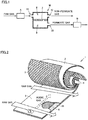
- FIG. 1 is a diagram schematically showing an example of a gas separation apparatus.
- the gas separation apparatus shown in FIG. 1 includes a gas separation membrane module M, a controller A for controlling the temperature, humidity, and pressure of the raw gas fed to gas separation membrane module M, and a back-pressure controller B for controlling the pressure of the permeate gas that has permeated through a gas separation membrane 2.
- Gas separation membrane module M includes a feed-side gas flow channel 8 and a permeate-side gas flow channel 9. Feed-side gas flow channel 8 and permeate-side gas flow channel 9 are partitioned from each other by gas separation membrane 2.
- Gas separation membrane module M includes a raw gas inlet 11 for introducing a raw gas into the interior thereof, a retentate gas outlet 12 for discharging a retentate gas that has not permeated through gas separation membrane 2, and a permeate gas outlet 22 for discharging a permeate gas that has permeated through gas separation membrane 2.
- the gas separation apparatus is not limited to the example shown in FIG. 1 and may also include two or more gas separation membrane modules M.
- the arrangement and number of gas separation membrane modules M provided in the gas separation apparatus can be selected according to the required throughput and recovery rate of the specific gas, and the size of the place to install the gas separation apparatus.
- gas separation membrane module M includes a gas separation membrane element including gas separation membrane 2 and a housing (container) for enclosing the gas separation membrane element.
- the housing is made of stainless steel, for example.
- Raw gas inlet 11, retentate gas outlet 12, and permeate gas outlet 22 can be provided, for example, in the housing.
- Gas separation membrane module M includes a gas separation membrane element to be enclosed in the housing.
- the gas separation membrane element includes one or more gas separation membranes accumulated.
- the one or more gas separation membranes accumulated may be, for example, one gas separation membrane folded, wound, or processed in a combined manner, or two or more gas separation membranes piled, folded, wound, or processed in a combined manner.
- Gas separation membrane module M may include one gas separation membrane element in the housing (single type). Alternatively, gas separation membrane module M may include two or more gas separation membrane elements to be enclosed in one housing. The arrangement and number of gas separation membrane elements can be selected according to the required recovery rate and throughput of the specific gas.
- two or more gas separation membrane elements may be arranged in parallel (parallel type) or in series (series type) in the housing.
- Arrangement in parallel at least means that a raw gas is distributed and introduced into the feed side of a plurality of gas separation membrane elements.
- Arrangement in series at least means that a retentate gas discharged from the discharge side of an upstream gas separation membrane element is introduced into the feed side of a downstream gas separation membrane element.
- the configuration may be such that gas separation membrane elements are disposed apparently in series in the housing, a raw gas is fed from raw gas inlet 11 provided in the housing to the two gas separation membrane elements in parallel, and a retentate gas that has not permeated through gas separation membrane 2 of each gas separation membrane element is discharged from retentate gas outlet 12 provided in the housing.
- raw gas inlet 11 and retentate gas outlet 12 provided in the housing may each be provided for every gas separation membrane element, or may also be shared by the two gas separation membrane elements.
- raw gas inlet 11 is provided as a single, and retentate gas outlet 12 is provided for every gas separation membrane element, or, conversely, raw gas inlet 11 is provided for every gas separation membrane element, and retentate gas outlet 12 is provided as a single.
- the form of the gas separation membrane element included in gas separation membrane module M is not particularly limited, and may be a spiral-wound type, a hollow fiber type, a tube type, a pleated type, or a plate & frame type, and is preferably a spiral-wound type.
- a spiral-wound gas separation membrane element includes a perforated core tube and a wound body wound around the core tube.
- the wound body is formed of a laminate including a flow channel member that forms a feed-side gas flow channel, a gas separation membrane including a hydrophilic resin composition layer, and a flow channel member forming a permeate-side gas flow channel laminated.
- FIG. 2 is a schematic perspective view partially having a cutaway portion, showing an example of a spiral-wound gas separation membrane element developed.
- FIG. 3 is a schematic perspective view partially having a developed portion, showing an example of a spiral-wound gas separation membrane element.
- the layer structures of the spiral-wound gas separation membrane element and the wound body (laminate) shown in FIG. 2 and FIG. 3 are shown as examples, and the present invention is not limited to these examples.
- a gas separation membrane element 1 shown in FIG. 2 and FIG. 3 which is a spiral-wound gas separation membrane element, includes at least one gas separation membrane 2, at least one flow channel member 3 forming a feed-side gas flow channel, and at least one flow channel member 4 forming a permeate-side gas flow channel, and may also include a wound body formed of a laminate 7, which is obtained by laminating them, wound around a core tube 5.
- the wound body may be in any shape, such as a circular cylinder or a polygonal cylinder. However, in the case of being enclosed in a housing (container) in a circular cylindrical shape, the wound body is preferably in a circular cylindrical shape.
- gas separation membrane element 1 is, in the case of being in the shape of a circular cylinder, such that the diameter is greater than or equal to 4 inches (about 10 cm), and the length is greater than or equal to 15 inches (about 38 cm), for example.
- Gas separation membrane element 1 usually has a diameter of less than or equal to 20 inches (about 51 cm) and a length of less than or equal to 100 inches (254 cm).
- Gas separation membrane element 1 may further include a fixing member (not shown), such as an outer periphery tape or a telescope prevention plate (ATD), in order to prevent the wound body from rewinding or the collapse of winding. Further, in order to ensure the strength against the load due to the internal pressure and external pressure on gas separation membrane element 1, it is also possible to provide an outer lapping (reinforcing layer) on the outermost periphery of the wound body.
- the outer periphery tape is wound around the outer periphery of the wound body and thus can suppress the rewinding of the wound body.
- the telescope prevention plate is attached to each end portion of the wound body and can suppress the occurrence of the winding collapse (telescope) phenomenon in the wound body during the use of gas separation membrane element 1.
- a reinforcing material such as a fiber-reinforced resin made of glass fibers impregnated with an epoxy resin may be used. It is preferable that after the reinforcing material is wound around the outermost periphery of the wound body, the epoxy resin is cured.
- the wound body forming gas separation membrane element 1 may be composed of, for example, laminate 7 formed of flow channel member 4 forming a permeate-side gas flow channel, gas separation membrane 2, flow channel member 3 forming a feed-side gas flow channel, and gas separation membrane 2 repeatedly laminated in this order.
- Flow channel member 3 forming a feed-side gas flow channel is a member to which a raw gas is fed, and the raw gas is fed to gas separation membrane 2 through this member.
- Gas separation membrane 2 includes a first porous layer and a hydrophilic resin composition layer that separates a specific gas contained in the raw gas fed from flow channel member 3 forming a feed-side gas flow channel and allows the specific gas to permeate therethrough.
- the first porous layer is provided for the purpose of supporting the hydrophilic resin composition layer upon the separation of a specific gas from the raw gas using gas separation membrane 2, and is usually provided adjacent to the hydrophilic resin composition layer.
- Flow channel member 4 forming a permeate-side gas flow channel is a member into which a permeate gas that has permeated through gas separation membrane 2 (containing at least part of the raw gas fed to gas separation membrane 2) flows, and guides the permeate gas to core tube 5.
- Core tube 5 collects the permeate gas flowing through flow channel member 4 forming a permeate-side gas flow channel.
- Gas separation membrane 2 constituting laminate 7 may include at least one second porous layer (protective layer) formed of a porous body.
- the second porous layer is disposed, for example, between gas separation membrane 2 and flow channel member 3 forming a feed-side gas flow channel.
- laminate 7 may include at least one third porous layer (reinforcement support layer) formed of a porous body.
- the third porous layer is disposed, for example, between gas separation membrane 2 and flow channel member 4 forming a permeate-side gas flow channel.
- Laminate 7 constituting the wound body includes a separation membrane-flow channel member composite body (membrane leaf).
- the separation membrane-flow channel member composite body is formed of gas separation membrane 2 folded in two and a flow channel member sandwiched in gas separation membrane 2 folded in two.
- the flow channel member sandwiched in gas separation membrane 2 folded in two is flow channel member 3 forming a feed-side gas flow channel, for example, but may also be flow channel member 4 forming a permeate-side gas flow channel.
- the separation membrane-flow channel member composite body usually includes flow channel member 3 forming a feed-side gas flow channel.
- gas separation membrane 2 is folded in two with the first porous layer being on the outer side, that is, the first porous layer being on the outer side of the hydrophilic resin composition layer.
- gas separation membrane 2 may be folded in two with the hydrophilic resin composition layer being on the outer side of the first porous layer.
- Gas separation membrane 2 constituting a separation membrane-flow channel member composite body includes a first porous layer formed of a porous body and a hydrophilic resin composition layer.
- the hydrophilic resin composition layer includes selective permeability for the specific gas.
- Gas separation membrane 2 can have selective permeability for a specific gas based on the dissolution/diffusion mechanism utilizing the difference between the solubility of gas molecules into the membrane and the diffusivity in the membrane.
- Gas separation membrane 2 preferably has selective permeability based on, in addition to the dissolution/diffusion mechanism, the facilitated transport mechanism, according to which a reaction product between a specific gas and a carrier is formed to promote the permeation of the specific gas.
- the selective permeability based on the facilitated transport mechanism can be imparted by adding a carrier capable of reversibly reacting with a specific gas to the hydrophilic resin composition layer included in gas separation membrane 2.
- the hydrophilic resin composition layer exhibits selective permeability for a specific gas in gas separation membrane 2 and has the function of allowing the specific gas to permeate therethrough.
- the hydrophilic resin composition layer contains a CO 2 carrier capable of reversibly reacting with CO 2 in the raw gas, and it is more preferable that the layer is a gel-like thin membrane containing a hydrophilic resin composition containing a CO 2 carrier capable of reversibly reacting with CO 2 in the raw gas and a hydrophilic resin serving as a medium that holds the CO 2 carrier and moisture.
- the thickness of the hydrophilic resin composition layer may be suitably selected according to the separation performance required for gas separation membrane 2, but is usually preferably within a range of greater than or equal to 0.1 ⁇ m and less than or equal to 600 ⁇ m, more preferable within a range of greater than or equal to 0.5 ⁇ m and less than or equal to 400 ⁇ m, and still more preferably within a range of greater than or equal to 1 ⁇ m and less than or equal to 200 ⁇ m.
- the hydrophilic resin contained in the hydrophilic resin composition layer for example, and as the specific gas for which gas separation membrane 2 exhibits selective permeability is CO 2 , which is an acidic gas, moisture is required for the reversible reaction between CO 2 and a CO 2 carrier, so that it is preferable that the hydrophilic resin has a hydrophilic group such as a hydroxyl group or an ion exchange group. It is more preferable that the hydrophilic resin includes a crosslinked hydrophilic resin, in which molecular chains are crosslinked to form a network structure, leading to high water-holding properties. Because a pressure difference is applied as a driving force for the permeation of a specific gas through gas separation membrane 2, it is preferable to use a hydrophilic resin including a crosslinked hydrophilic resin also in terms of the pressure resistance strength required for gas separation membrane 2.
- the raw gas contains water vapor.
- the polymer forming the hydrophilic resin has, for example, a structural unit derived from an alkyl acrylate, an alkyl ester methacrylate, a vinyl ester of a fatty acid, or a derivative thereof.
- examples of such polymers having hydrophilicity include polymers obtained by polymerizing monomers such as acrylic acid, itaconic acid, crotonic acid, methacrylic acid, and vinyl acetate.
- resins having a carboxyl group as an ion exchange group such as a polyacrylic acid resin, a polyitaconic acid resin, a polycrotonic acid resin, and a polymethacrylic acid resin; a polyvinyl alcohol resin having a hydroxy group; and copolymers thereof such as an acrylic acid-vinyl alcohol copolymer resin, an acrylic acid-methacrylic acid copolymer resin, an acrylic acid-methyl methacrylate copolymer resin, and a methacrylic acid-methyl methacrylate copolymer resin.
- the crosslinked hydrophilic resin may be prepared by allowing a polymer having hydrophilicity to react with a crosslinking agent, or may also be prepared by copolymerizing a monomer that serves as the raw material of the polymer having hydrophilicity with a crosslinkable monomer.
- the crosslinking agent and the crosslinkable monomer are not particularly limited, and conventionally known crosslinking agents and crosslinkable monomers are applicable.
- a carrier is a substance capable of reversibly reacting with a specific gas in the raw gas.
- a carrier By adding a carrier, the function of the hydrophilic resin composition layer to feed a specific gas in the raw gas to flow channel member 4 forming a permeate-side gas flow channel can be promoted.
- As a carrier at least one kind of the carrier can be present in the hydrophilic resin composition layer containing a hydrophilic resin. The carrier reversibly reacts with a specific gas dissolved in water present in the hydrophilic resin composition layer, thereby selectively allowing the specific gas to permeate therethrough.
- the hydrophilic resin composition layer may also contain, for example, a hydration catalyst for the acidic gas, and/or the below-described surfactant as additives.
- a hydration catalyst for the acidic gas When used together, the reaction rate of the acidic gas and the carrier capable of reversibly reacting with the acidic gas can be improved.
- an oxo acid compound is contained, it is more preferable that at least one elemental oxo acid compound selected from the group consisting of group 14 elements, group 15 elements, and group 16 elements is contained, and it is still more preferable that at least one member selected from the group consisting of tellurious acid compounds, selenious acid compounds, arsenious acid compounds, and orthosilicic acid compounds is contained.
- Gas separation membrane 2 includes a first porous layer. It is preferable that the first porous layer has porosity with high gas permeability so as not cause diffusion resistance against the gas component that has permeated through the hydrophilic resin composition layer.
- the first porous layer may have a single-layer structure or may also have a laminate structure including two or more layers. It is preferable that the member of the first porous layer has heat resistance according to the process conditions in plants for the production of hydrogen, urea, or the like, where gas separation membrane 2 is to be applied.
- heat resistance means that after the member of the first porous layer or the like is stored for 2 hours under the temperature conditions equal to or higher than the process conditions, visually recognizable curling due to thermal contraction or thermofusion does not occur, for example, and the form before storage is maintained.
- materials constituting the first porous layer include polyolefin resins such as polyethylene (PE) and polypropylene (PP); fluorine-containing resins such as polytetrafluoroethylene (PTFE), polyvinyl fluoride (PVF), and polyvinylidene fluoride (PVDF); polyester resins such as polyethylene terephthalate (PET), polyethylene naphthalate, and high-molecular-weight polyesters; resin materials such as polystyrene (PS), polyethersulfone (PES), polyphenylene sulfide (PPS), polysulfone (PSF), polyimide (PI), polyetherimide (PEI), polyetheretherketone (PEEK), heat-resistant polyamides, aramids, and polycarbonates; and inorganic materials such as metals, glasses, and ceramics. Among them, fluorine-containing resins and PP are more preferable.
- fluorine-containing resins and PP are more preferable.
- the thickness of the first porous layer is not particularly limited. However, in terms of mechanical strength, usually, the thickness is preferably within a range of greater than or equal to 10 ⁇ m and less than or equal to 3000 ⁇ m, more preferably within a range of greater than or equal to 10 ⁇ m and less than or equal to 500 ⁇ m, and still more preferably within a range of greater than or equal to 15 ⁇ m and less than or equal to 150 ⁇ m.
- the average pore size of the pores of the first porous layer is not particularly limited, but is preferably less than or equal to 10 ⁇ m, and more preferably within a range of greater than or equal to 0.005 ⁇ m and less than or equal to 1.0 ⁇ m.
- the porosity of the first porous layer is preferably within a range of greater than or equal to 5% and less than or equal to 99%, and more preferably within a range of greater than or equal to 30% and less than or equal to 90%.
- Gas separation membrane 2 may include a second porous layer provided on the surface of the hydrophilic resin composition layer on the opposite side from the first porous layer, for example, between the hydrophilic resin composition layer and flow channel member 3 forming a feed-side gas flow channel.
- the hydrophilic resin composition layer and flow channel member 3 forming a feed-side gas flow channel may rub against each other.
- the second porous layer is provided, the hydrophilic resin composition layer is protected, and the occurrence of damage due to the rubbing can be suppressed.
- the second porous layer is not particularly limited as long as it does not cause much friction with flow channel member 3 forming a feed-side gas flow channel, and its material has excellent gas permeability.
- a material having heat resistance according to the temperature conditions under which gas separation membrane 2 is used is preferable, and the same materials as those mentioned as materials for constituting the first porous layer may be suitably used, for example.
- the second porous layer for example, a porous membrane, a nonwoven fabric, a woven fabric, or a net having an average pore size of greater than or equal to 0.001 ⁇ m and less than or equal to 10 ⁇ m can be suitably selected and used.
- the second porous layer may have a single-layer structure or may also have a laminate structure including two or more layers.
- Gas separation membrane 2 may include a third porous layer provided on the surface of the first porous layer on the opposite side from the hydrophilic resin composition layer, for example, between the first porous layer and flow channel member 4 forming a permeate-side gas flow channel.
- a third porous layer provided on the surface of the first porous layer on the opposite side from the hydrophilic resin composition layer, for example, between the first porous layer and flow channel member 4 forming a permeate-side gas flow channel.
- the third porous layer is not particularly limited as long as it has pressure resistance strength and stretch resistance, and its structure and material have gas permeability.
- a material having heat resistance according to the temperature conditions under which gas separation membrane 2 is used is preferable, and the same materials as those mentioned as materials for constituting the first porous layer may be suitably used, for example.
- the third layer for example, a nonwoven fabric, a woven fabric, or a net having an average pore size of greater than or equal to 0.001 ⁇ m and less than or equal to 10 ⁇ m can be suitably selected and used.
- the third porous layer may have a single-layer structure or may also have a laminate structure including two or more layers.
- Flow channel member 3 forming a feed-side gas flow channel forms a flow channel space to which the raw gas is fed. This flow channel space introduces the raw gas into the interior of the wound body, and the raw gas is fed to gas separation membrane 2.
- flow channel member 3 forming a feed-side gas flow channel has the function as a flow channel material that forms a flow channel space for the raw gas and also the function to minimize the pressure loss of the raw gas to be fed as much as possible while causing a turbulent flow in the raw gas to promote the surface renewal on the feed-side surface of gas separation membrane 2.
- flow channel member 3 forming a feed-side gas flow channel has a network shape (net-like, mesh-like, etc.). Depending on the network shape, the flow channel for the raw gas changes. Therefore, the shape of the unit cell of the network in flow channel member 3 forming a feed-side gas flow channel is preferably selected according to the purpose, for example, from a square, a rectangle, a rhombus, and a parallelogram.
- the material constituting flow channel member 3 forming a feed-side gas flow channel As materials for constituting flow channel member 3 forming a feed-side gas flow channel, resins and inorganic materials such as metals, glasses, and ceramics can be mentioned. It is preferable that the material constituting flow channel member 3 forming a feed-side gas flow channel has heat resistance according to the temperature conditions under which gas separation membrane 2 is used. In addition, in terms of maintaining the function as a flow channel material that forms a flow channel space of the raw gas, it is preferable that the material constituting flow channel member 3 forming a feed-side gas flow channel has high mechanical strength (rigidity).
- materials having high heat resistance and high rigidity include resin materials such as PE, PP, PTFE, PS, PPS, PES, PEEK, PI, and polycyclohexylene dimethylene terephthalate (PCT); inorganic materials such as metals, glasses, and ceramics; and materials combining a resin material and an inorganic material.
- resin materials such as PE, PP, PTFE, PS, PPS, PES, PEEK, PI, and polycyclohexylene dimethylene terephthalate (PCT)
- inorganic materials such as metals, glasses, and ceramics
- materials combining a resin material and an inorganic material include PE, PP, PTFE, PS, PPS, PES, PEEK, PI, and polycyclohexylene dimethylene terephthalate (PCT)
- flow channel member 3 forming a feed-side gas flow channel includes a layer formed of a nonwoven fabric, a woven fabric, or a net containing at least one material selected from the group consisting of resins, metals, and glasses, and it is more preferable to include a layer formed of a nonwoven fabric, a woven fabric, or a net containing at least one material selected from the group consisting of PE, PP, PTFE, PS, PPS, PES, PEEK, PI, PCT, resins, metals, and glasses.
- Flow channel member 3 forming a feed-side gas flow channel may have a single-layer structure or may also have a laminate structure including two or more layers.
- a laminate structure including two or more of layers of the above nonwoven fabric, woven fabric, or net is also possible.
- the thickness of flow channel member 3 forming a feed-side gas flow channel is preferably within a range of greater than or equal to 10 ⁇ m and less than or equal to 7500 ⁇ m, more preferably within a range of greater than or equal to 50 ⁇ m and less than or equal to 5000 ⁇ m, and still more preferably within a range of greater than or equal to 100 ⁇ m and less than or equal to 2500 ⁇ m.
- Flow channel member 4 forming a permeate-side gas flow channel forms a flow channel space through which a permeate gas that has permeated through gas separation membrane 2 flows. This flow channel space introduces the permeate gas into core tube 5.
- flow channel member 4 forming a permeate-side gas flow channel has the function as a flow channel material that forms a flow channel space for the permeate gas and also the function to cause a turbulent flow in the permeate gas to promote the surface renewal on the permeate-side surface of gas separation membrane 2.
- flow channel member 4 forming a permeate-side gas flow channel has a network shape (net-like, mesh-like, etc.). Depending on the network shape, the flow channel for the raw gas changes. Therefore, the shape of the unit cell of the network in flow channel member 4 forming a permeate-side gas flow channel is preferably selected according to the purpose, for example, from a square, a rectangle, a rhombus, and a parallelogram.
- the material constituting flow channel member 4 forming a permeate-side gas flow channel is not particularly limited. However, a material having heat resistance according to the temperature conditions under which gas separation membrane 2 is used is preferable, and the same materials as the resin materials mentioned as materials for constituting the first porous layer may be suitably used, for example. Specifically, PTFE, PES, PSF, PEEK, PI, and metals are preferable, and PTFE, PPS, PEEK, and metals are more preferable.
- Flow channel member 4 forming a permeate-side gas flow channel may have a single-layer structure or may also have a laminate structure including two or more layers.
- Core tube 5 is a conduct tube for collecting the permeate gas that has permeated through gas separation membrane 2 and discharging the same from gas separation membrane element 1.
- the material for core tube 5 is not particularly limited, but is preferably a material having heat resistance according to the temperature conditions under which gas separation membrane 2 is used.
- a material having mechanical strength is preferable.
- stainless steel is suitably used, for example.
- the diameter, length, and thickness of core tube 5 are suitably set according to the size of gas separation membrane element 1, the number of separation membrane-flow channel member composite bodies in laminate 7, the amount of permeate gas, and the mechanical strength required for core tube 5.
- Core tube 5 is preferably a circular tube in the case where the wound body is in the shape of a circular cylinder, and is preferably a polygonal tube in the case where the wound body is in the shape of a polygonal cylinder.
- core tube 5 has a plurality of holes 30 on the outer peripheral surface of core tube 5.
- the holes 30 communicate between the flow channel space for the permeate gas in flow channel member 4 forming a permeate-side gas flow channel and the inner hollow space of core tube 5.
- the number of holes 30 and the size of holes 30 provided in core tube 5 are determined in consideration of the amount of permeate gas fed from flow channel member 4 forming a permeate-side gas flow channel or the mechanical strength required for core tube 5.
- Holes 30 provided in core tube 5 may be formed at equal intervals in the direction parallel to the axis of core tube 5, or may also be concentrated on one end side of core tube 5.
- a raw gas When a raw gas is introduced into the housing from raw gas inlet 11 of gas separation membrane module M, the raw gas is continuously fed from a feed-side end portion 31 of gas separation membrane element 1 in the housing to flow channel member 3 forming a feed-side gas flow channel (the arrow a in FIG. 3 ), and a specific gas contained in the raw gas flowing through flow channel member 3 forming a feed-side gas flow channel permeates through gas separation membrane 2.
- the permeate gas that has permeated through gas separation membrane 2 flows in flow channel member 4 forming a permeate-side gas flow channel and is then fed to core tube 5 from holes 30, continuously discharged from the outlet 32 of core tube 5 (the arrow b in FIG.
- the gas separation method according to the present invention includes the following steps:
- the raw gas feeding step is performed after the module preparation step.
- the pressure increase step and the temperature increase step are performed after the module preparation step and before the raw gas feeding step.
- the temperature increase step may be performed after the pressure increase step, and the pressure increase step may be performed after the temperature increase step.
- This step is a step of preparing a gas separation membrane module M in which a gas separation membrane element 1 including a gas separation membrane 2 is enclosed in a housing.
- Gas separation membrane module M is used as incorporated into the gas separation apparatus shown in FIG. 1 , for example.
- Gas separation membrane module M prepared in this step includes gas separation membrane element 1 enclosed in the housing as described above, and gas separation membrane element 1 includes gas separation membrane 2 including a first porous layer and a hydrophilic resin composition layer.
- the hydrophilic resin composition layer included in gas separation membrane 2 of gas separation membrane module M prepared in this step has been adjusted to contain moisture.
- the moisture content of the hydrophilic resin composition layer is an amount that allows the equilibrium relative humidity at a temperature of 23 °C of the gas phase portion in the housing to be greater than or equal to 10%RH
- the equilibrium relative humidity at a temperature of 23°C of the gas phase portion in the housing means the following value: the relative humidity at a temperature of 23°C of the gas phase portion in a hermetically sealed state is continuously or intermittently measured, and the measured value at which the measured value shows no change and starts showing a certain value is defined as the equilibrium relative humidity.
- the equilibrium relative humidity is preferably greater than or equal to 15%RH, more preferably greater than or equal to 20%RH, and still more preferably greater than or equal to 25%RH.
- the equilibrium relative humidity may be less than or equal to 100%RH However, in terms of ease of realization, it is preferably less than or equal to 90%RH, and more preferably less than or equal to 80%RH.
- Gas separation membrane module M including the hydrophilic resin composition layer that has been adjusted to contain moisture to such a degree that the equilibrium relative humidity can be greater than or equal to 10%RH can be assembled by a method including the following steps, for example.
- the moisture content of the hydrophilic resin composition layer containing moisture is a moisture content of such a degree that the equilibrium relative humidity can be greater than or equal to 10%RH
- the moisture content does not necessarily have to be such a degree that the equilibrium relative humidity can be greater than or equal to 10%RH
- step b) above includes, for example, a step of distributing a humidified gas in the interior of gas separation membrane module M including gas separation membrane element 1 enclosed in the housing.
- the humidified gas a humidified inert gas can be mentioned, for example. It is preferable that the inert gas is inert to gas separation membrane module M or gas separation membrane element 1 (and the hydrophilic resin composition layer included therein).
- the humidified gas is preferably a humidified nitrogen gas or a humidified rare gas such as a humidified argon gas or humidified helium gas, and preferably a humidified nitrogen gas.
- a method of distributing a humidified gas is applicable.
- a hydrophilic resin composition layer having a desired moisture content can be obtained by the following method, for example.
- a gas separation membrane element 1 including a hydrophilic resin composition layer is enclosed in a housing to assemble a gas separation membrane module M.
- a humidified gas having a relative humidity of A%RH (A is a value of greater than or equal to 10%RH) at a temperature of 23°C is continuously fed from a raw gas inlet 11 of gas separation membrane module M.
- A is a value of greater than or equal to 10%RH
- the hydrophilic resin composition layer absorbs the moisture of the humidified gas.
- a humidified gas having a relative humidity of less than A%RH is discharged from a retentate gas outlet 12 of gas separation membrane module M.
- a hydrophilic resin composition layer having a moisture content of such a degree that the equilibrium relative humidity can be greater than or equal to 10%RH can be obtained.
- the humidified gas is fed from raw gas inlet 11 in the above example, the present invention is not limited thereto, and the humidified gas may be fed from an aperture that gas separation membrane module M has, such as retentate gas outlet 12.
- the equilibrium relative humidity described above is an equilibrium relative humidity at a temperature of 23°C
- the module preparation step itself does not necessarily have to be performed at a temperature of 23 °C.
- the operation of supplying moisture to the hydrophilic resin composition layer before enclosing gas separation membrane element 1 in the housing may be performed at an arbitrary temperature range, and the temperature range may be a temperature range of higher than or equal to 0°C and lower than or equal to 50°C, for example.
- the temperature of the humidified gas fed to the interior of gas separation membrane module M does not necessarily have to be 23°C, and may be a temperature range of higher than or equal to 0°C and lower than or equal to 50°C, for example.
- the hydrophilic resin composition layer has been adjusted to contain moisture to such a degree that the equilibrium relative humidity can be a predetermined value or more.
- This step is a step of increasing the pressure in the interior of gas separation membrane module M.
- the pressure increase step is performed before the temperature increase step.
- the gas separation method includes a module preparation step, a pressure increase step, a temperature increase step, and a raw gas feeding step in this order.
- the pressure increase step is performed after the temperature increase step.
- the gas separation method includes a module preparation step, a temperature increase step, a pressure increase step, and a raw gas feeding step in this order.
- the gas separation method includes a module preparation step, a pressure increase step, a temperature increase step, and a raw gas feeding step in this order.
- the pressure increase step is performed subsequent to the step of preparing a gas separation membrane module M including a hydrophilic resin composition layer that has been adjusted to contain moisture to such a degree that the equilibrium relative humidity at a temperature of 23 °C of the gas phase portion in the housing can be greater than or equal to 10%RH (module preparation step).
- the pressure increase step may be performed before the relative humidity of the gas phase portion in the housing reaches equilibrium, or may also be performed after equilibrium is reached.
- the pressure in the interior of gas separation membrane module M is increased by feeding a gas to the interior of gas separation membrane module M, that is, to the interior of the housing.
- the gas can be fed from, for example, an aperture such as a raw gas inlet 11, a retentate gas outlet 12, or a like that gas separation membrane module M has.
- the interior of gas separation membrane module M to which the gas is fed is a closed system.
- a closed system for example, methods in which the apertures other than the aperture through which the gas is fed are closed, the valve of the gas line communicating with the aperture is closed, a back-pressure valve is provided and adjusted can be mentioned.
- the gas is not particularly limited as long as it is different from the raw gas, but is preferably an inert gas. It is preferable that the inert gas is inert to gas separation membrane module M or gas separation membrane element 1 (and the hydrophilic resin composition layer included therein).
- the gas is preferably a nitrogen gas or a rare gas such as an argon gas or a helium gas, and more preferably a nitrogen gas.
- the gas is a dry gas containing no moisture or having a sufficiently low moisture content.
- the gas has a water partial pressure lower than the maximum saturation water vapor pressure in the pressure increase step, and it is more preferable that the water partial pressure is lower than the minimum saturation water vapor pressure in the pressure increase step.
- the water partial pressure means the partial pressure that moisture in the gas shows in the pressure increase step.
- the maximum saturation water vapor pressure in the pressure increase step is, for example, in the case where the temperature in the interior of gas separation membrane module M varies in the pressure increase step, the saturation water vapor pressure at the highest temperature in the pressure increase step.
- the minimum saturation water vapor pressure in the pressure increase step is, for example, in the case where the temperature in the interior of gas separation membrane module M varies in the pressure increase step, the saturation water vapor pressure at the lowest temperature in the pressure increase step.
- the moisture content of the gas is preferably less than or equal to 10 mass%, more preferably less than or equal to 5 mass%, and still more preferably less than or equal to 1 mass%.
- the interior of gas separation membrane module M includes the feed side of the interior of gas separation membrane module M, that is, feed-side gas flow channel 8 shown in FIG. 1 . It is more preferable that of the feed side and permeate side of gas separation membrane module M, only the pressure on the feed side is increased.
- the pressure in the interior of gas separation membrane module M is increased to greater than or equal to 0.3 MPaG, for example.
- the pressure in the interior of gas separation membrane module M is preferably increased to greater than or equal to 0.5 MPaG, more preferably increased to greater than or equal to 0.6 MPaG, and still more preferably increased to greater than or equal to 0.7 MPaG.
- the pressure in the interior of gas separation membrane module M is increased to greater than or equal to 25% of the working pressure, for example.
- the pressure in the interior of gas separation membrane module M is preferably increased to greater than or equal to 45% of the working pressure, more preferably greater than or equal to 50% of the working pressure, and still more preferably greater than or equal to 60% of the working pressure.
- the working pressure is the pressure of the raw gas fed in the below-described raw gas feeding step.
- the ultimate pressure in the pressure increase step may be a pressure equivalent to the working pressure, higher than working pressure, or lower than the working pressure.
- the ultimate pressure in the pressure increase step is preferably usually less than or equal to 10 MPaG, and more preferably less than or equal to 8 MPaG.
- the pressure at the time of pressure reduction is preferably more than the atmospheric pressure, and more preferably greater than or equal to 0.1 MPaG.
- the temperature in the interior of gas separation membrane module M, where the pressure is increased is usually equal to or higher than the outdoor temperature.
- the temperature is the same as or equivalent to the outdoor temperature.
- This step is a step of increasing the temperature in the interior of gas separation membrane module M.
- “To increase the temperature” means to increase the temperature higher than the temperature in the interior of gas separation membrane module M immediately before this step.
- the temperature increase step may be performed with the interior of gas separation membrane module M being a closed system.
- the temperature increase step is performed subsequent to the step of preparing a gas separation membrane module M including a hydrophilic resin composition layer that has been adjusted to contain moisture to such a degree that the equilibrium relative humidity at a temperature of 23 °C of the gas phase portion in the housing can be greater than or equal to 10%RH (module preparation step).
- the temperature increase step may be performed before the relative humidity of the gas phase portion in the housing reaches equilibrium, or may also be performed after equilibrium is reached.
- the temperature increase in the interior of gas separation membrane module M can be achieved by providing a heater in the exterior or interior of gas separation membrane module M, the exterior of gas separation membrane element 1, or two or more places selected from them.
- heaters examples include jacket heaters, jackets or pipes that can be heated by distributing a heat medium, and induction heating devices. They can be used alone or in combination.
- the temperature in the interior of gas separation membrane module M is increased to a temperature higher than the dew point of the raw gas in the raw gas feeding step described below.
- the temperature in the interior of gas separation membrane module M is preferably increased to higher than or equal to 100°C, more preferably increased to higher than or equal to 105°C, and still more preferably increased to higher than or equal to 110°C.
- the ultimate temperature in the temperature increase step is less than 100°C, sufficient separation efficiency may not be exhibited, or the suppressing effect on the drop in separation efficiency relative to the case of gas separation on laboratory scale described above may not be sufficient.
- the ultimate temperature in the temperature increase step is usually preferably lower than or equal to 200°C, and more preferably lower than or equal to 150°C.
- the difference between the ultimate temperature in the interior of gas separation membrane module M in the temperature increase step and the temperature in the interior of gas separation membrane module M immediately before the temperature increase step is preferably higher than or equal to 10°C, more preferably higher than or equal to 30°C, and still more preferably higher than or equal to 60°C.
- such a temperature range may be maintained (e.g., 1 minute to 50 hours).
- the pressure in the interior of gas separation membrane module M, where the temperature is increased is not particularly limited.
- the pressure in the interior of gas separation membrane module M in the temperature increase step can be higher than the ultimate pressure in the pressure increase step.
- the pressure in the interior of gas separation membrane module M in the temperature increase step may be lower than the ultimate pressure in the pressure increase step.
- This step is a step of feeding a raw gas to the interior of gas separation membrane module M, which is performed after the pressure increase step and the temperature increase step.
- the raw gas is fed from a raw gas inlet 11 to the feed side of gas separation membrane module M. As a result of feeding the raw gas, the gas separation operation is started.
- the temperature, humidity, and pressure of the raw gas fed to the interior of gas separation membrane module M have been adjusted with a controller A ( FIG. 1 ).
- a controller A FIG. 1
- the reversible reaction between an acidic gas (CO 2 ) and an acidic gas carrier (CO 2 carrier) can be promoted, whereby the separation efficiency can be enhanced.
- the temperature of the raw gas fed to the interior of gas separation membrane module M and the temperature in the interior of gas separation membrane module M at the start of raw gas feeding may be the same as, higher than or equal to, or lower than or equal to the ultimate temperature in the interior of gas separation membrane module M in the temperature increase step or the temperature in the pressure increase step.
- the temperature of the raw gas fed to the interior of gas separation membrane module M and the temperature in the interior of gas separation membrane module M at the start of raw gas feeding are higher than or equal to 100°C and lower than or equal to 200°C, for example, and preferably higher than or equal to 110°C and lower than or equal to 150°C.
- the pressure of the raw gas fed to the interior of gas separation membrane module M and the pressure in the interior of gas separation membrane module M at the start of raw gas feeding are, in terms of separation efficiency, is greater than or equal to 0.5 MPaG and less than or equal to 10 MPaG, preferably greater than or equal to 0.6 MPaG and less than or equal to 8 MPaG, and more preferably greater than or equal to 0.7 MPaG and less than or equal to 8 MPaG.
- the gas separation operation can be continuously performed.
- the temperature and pressure in the interior of gas separation membrane module M at the time of continuous operation are the same as the temperature and pressure at the start of raw gas feeding described above, respectively.
- a sweep gas selected from inert gases may be fed to the permeate side of gas separation membrane module M.
- the sweep gas can be fed into core tube 5 of gas separation membrane element 1.
- the retentate gas that has not permeated through gas separation membrane 2 is continuously discharged from retentate gas outlet 12 of gas separation membrane module M.
- this retentate gas is fed to a step of purifying the retentate gas.
- the retentate gas purification step may be a step utilizing an adsorption method, a physical absorption method, a chemical absorption method, a distillation method, or a cryogenic separation method.
- a roughly purified hydrogen gas obtained by separating and removing part of CO 2 contained in the synthetic gas is obtained.
- the roughly purified hydrogen gas is fed to a second purification step utilizing a chemical absorption method to separate and remove CO 2 contained in the roughly purified hydrogen gas, whereby a purified hydrogen gas can be obtained.
- CO 2 separation including the first purification step using gas separation membrane module M as compared with the case where the first purification step is not preformed, the amount of heat energy consumption required for the entire purification step can be suppressed low.
- the obtained coating liquid was applied onto the hydrophilic PTFE porous membrane side of a two-layer porous membrane including a hydrophilic PTFE porous membrane ("WPW-020-80" manufactured by Sumitomo Electric Fine Polymer, Inc., thickness: 80 ⁇ m, pore size: 0.2 ⁇ m) and a hydrophobic PTFE membrane ("Fluoropore FP010" manufactured by Sumitomo Electric Fine Polymer, Inc., thickness: 60 ⁇ m, pore size: 0.1 ⁇ m) using an applicator (application thickness: 500 ⁇ m), then allowed to dry naturally at room temperature, and further dried at 120°C for 2 hours to form a hydrophilic resin composition layer, thereby giving a gas separation membrane.
- WPW-020-80 manufactured by Sumitomo Electric Fine Polymer, Inc., thickness: 80 ⁇ m, pore size: 0.2 ⁇ m
- a hydrophobic PTFE membrane (“Fluoropore FP010” manufactured by Sumi
- the gas separation apparatus equipped with a gas separation membrane module 51 including a flat-shaped gas separation membrane shown in FIG. 4 was fabricated.
- the gas separation membrane obtained above was cut into a size of 5 cm ⁇ 5 cm, and the resulting flat membrane sample 50 was set in a flow-type gas permeation cell made of stainless steel, and fixed using an O-ring made of fluoro-rubber as a sealant between a feed-side chamber 52 and a permeate-side chamber 53, thereby fabricating gas separation membrane module 51.
- the cell and the pipe for feeding gases to gas separation membrane module 51 is installed in a thermostat that can be set at a predetermined temperature.
- one end of a first-layer flow channel member forming a permeate-side gas flow channel was fixed to the core tube.
- an adhesive was applied in a belt-like form.
- a first-layer separation membrane-flow channel member composite body was laminated on the first-layer flow channel member forming a permeate-side gas flow channel.
- the separation membrane-flow channel member composite body was laminated to be spaced away from the core tube.
- a second-layer separation membrane-flow channel member composite body was laminated on the second-layer flow channel member forming a permeate-side gas flow channel. At this time, the lamination position of the second-layer separation membrane-flow channel member composite body was more spaced away from the core tube than the second-layer flow channel member forming a permeate-side gas flow channel.
- both end portions of the wound body in direction parallel to the axis of the wound body were cut, and a telescope prevention plate was attached in contact with the cut surface of each end portion.
- an outer lapping (reinforcing layer) was formed using a fiber-reinforced resin made of glass fibers impregnated with an epoxy resin, thereby forming a gas separation membrane element 70.
- the obtained gas separation membrane element 70 had a diameter of 4 inches (about 10 cm) and a length of 15 inches (about 38 cm).
- gas separation membrane element 70 was enclosed in a housing 71 made of stainless steel to give a gas separation membrane module 72.
- separation membrane module 72 Using separation membrane module 72, a gas separation apparatus shown in FIG. 5 was fabricated. As shown in FIG. 5 , in gas separation membrane module 72, the gap between gas separation membrane element 70 and housing 71 was sealed with a sealant 73 so that the gas fed into housing 71 was fed into gas separation membrane element 70.
- a gas separation operation was performed according to the following procedures, and the ratio (CO 2 /H 2 ) of CO 2 permeance to H 2 permeance was measured.
- the ratio (H1/H0) of the permeance ratio H1 to the permeance ratio H0 was evaluated in accordance with the following evaluation criteria.
- the obtained coating liquid was applied to a hydrophobic PTFE porous membrane ("POREFLON HP-010-50" manufactured by Sumitomo Electric Fine Polymer, Inc., thickness: 50 ⁇ m, pore size: 0.1 ⁇ m) to serve as a first porous layer, and then dried at a temperature of about 120°C for 5 minutes, thereby forming a coating film. Further, the application and drying of the coating liquid were repeated several times to form a hydrophilic resin composition layer on the first porous layer, thereby obtaining a gas separation membrane.
- a hydrophobic PTFE porous membrane (“POREFLON HP-010-50" manufactured by Sumitomo Electric Fine Polymer, Inc., thickness: 50 ⁇ m, pore size: 0.1 ⁇ m)
- a flat membrane sample 50 was fabricated in the same manner as in (1) of Comparative Example 1, and the gas separation apparatus equipped with a gas separation membrane module 51 including a flat-shaped gas separation membrane shown in FIG. 4 was fabricated.
- a gas separation operation was performed according to the following procedures, and the ratio (CO 2 /H 2 ) of CO 2 permeance to H 2 permeance was measured.
- gas separation membrane element 70 Using gas separation membrane element 70, a gas separation membrane module 72 was fabricated in the same manner as in (2) of Comparative Example 1, and then the gas separation apparatus shown in FIG. 5 was fabricated.
- the ratio (A1-1/A0-1) of permeance ratio A1-1 to permeance ratio A0-1 was calculated, and evaluated in accordance with the above evaluation criteria.
- the result of evaluation was B.
- the ratio (A1-2/A0-2) of permeance ratio A1-2 to permeance ratio A0-2 was calculated, and evaluated in accordance with the above evaluation criteria.
- the result of evaluation was A.
- the gas separation operation was performed in the same manner as in (1) of Example 2, except that in the procedure [a], after fabricating a gas separation apparatus equipped with a gas separation membrane module 51, a nitrogen gas at a temperature of 23°C having a relative humidity of 35%RH at a temperature of 23°C was fed from the raw gas inlet on the feed side of gas separation membrane module 51, the relative humidity at a temperature of 23 °C of the nitrogen gas discharged from the retentate gas outlet on the feed side was measured, and the nitrogen gas feeding was continued until the relative humidity at a temperature of 23 °C of the nitrogen gas was stabilized at 35%RH The ratio (CO 2 /H 2 ) of CO 2 permeance to H 2 permeance was then measured. Hereinafter, this permeance ratio is referred to as "permeance ratio A0-3.”
- the gas separation operation was performed in the same manner as in (2) of Example 2, except that in the procedure [a], a nitrogen gas at a temperature of 23 °C having a relative humidity of 35%RH at a temperature of 23°C was fed from the raw gas inlet of gas separation membrane module 72, the relative humidity at a temperature of 23°C of the nitrogen gas discharged from the retentate gas outlet was measured, and the nitrogen gas feeding was continued until the relative humidity at a temperature of 23°C of the nitrogen gas was stabilized at 35%RH The ratio (CO 2 /H 2 ) of CO 2 permeance to H 2 permeance was then measured.
- this permeance ratio A1-3 this permeance ratio is referred to as "permeance ratio A1-3.”
- the ratio (A1-3/A0-3) of permeance ratio A1-3 to permeance ratio A0-3 was calculated, and evaluated in accordance with the above evaluation criteria.
- the result of evaluation was A.
Landscapes
- Chemical & Material Sciences (AREA)
- Chemical Kinetics & Catalysis (AREA)
- Engineering & Computer Science (AREA)
- Analytical Chemistry (AREA)
- General Chemical & Material Sciences (AREA)
- Oil, Petroleum & Natural Gas (AREA)
- Dispersion Chemistry (AREA)
- Separation Using Semi-Permeable Membranes (AREA)
Claims (10)
- Verfahren zum Abtrennen eines spezifischen Gases aus einem Rohgas, welches das spezifisches Gas enthält, unter Verwendung eines Gastrennungsmembranmoduls, wobei das spezifische Gas Kohlenstoffdioxid (CO2) ist,
das Gastrennungsmembranmodul ein Gehäuse und ein in dem Gehäuse umschlossenes Gastrennungsmembranelement enthält,
das Gastrennungsmembranelement eine Gastrennungsmembran enthält, welche eine Schicht einer hydrophilen Harzzusammensetzung enthält, um selektiv eine Permeation des spezifischen Gases zu ermöglichen,
die Methode die folgenden Schritte umfasst:Herstellen des Gastrennungsmembranmoduls;Erhöhen eines Drucks in einem Inneren des Gastrennungsmembranmoduls; Erhöhen einer Temperatur im Inneren des Gastrennungsmembranmoduls; und Zuführen des Rohgases zu dem Inneren des Gastrennungsmembranmoduls,wobeidie Schicht der hydrophilen Harzzusammensetzung, die in dem im Schritt des Herstellens des Gastrennungsmembranmoduls hergestellten Gastrennungsmembranmodul enthalten ist, eingestellt wird, um Feuchtigkeit zu enthalten,ein Feuchtigkeitsgehalt der Schicht der hydrophilen Harzzusammensetzung eine Menge ist, die einer relativen Gleichgewichtsfeuchtigkeit bei einer Temperatur von 23 °C eines Gasphasenanteils im Gehäuse ermöglicht, größer oder gleich 10 %RF zu sein,der Schritt des Zuführens des Rohgases nach dem Schritt des Herstellens des Gastrennungsmembranmoduls durchgeführt wird,der Schritt des Erhöhens eines Drucks und der Schritt des Erhöhens einer Temperatur nach dem Schritt des Herstellens des Gastrennungsmembranmoduls und vor dem Schritt des Zuführens des Rohgases durchgeführt werden undzu Beginn des Rohgaszuführens die Temperatur im Inneren des Gastrennungsmembranmoduls größer oder gleich 100 °C und kleiner oder gleich 200 °C ist und der Druck im Inneren des Gastrennungsmembranmoduls größer oder gleich 0.5 MPaG und kleiner oder gleich 10 MPaG ist. - Verfahren nach Anspruch 1, wobei der Schritt des Herstellens des Gastrennungsmembranmoduls mindestens einen der Schritte enthält:Umnschließen des Gastrennungsmembranelements, welches die Gastrennungsmembran enthält, welche die Feuchtigkeit enthaltende Schicht der hydrophilen Harzzusammensetzung enthält, in dem Gehäuse; undHinzufügen von Feuchtigkeit zu der Schicht der hydrophilen Harzzusammensetzung des im Gehäuse umschlossenen Gastrennungsmembranelements.
- Verfahren nach Anspruch 2, wobei der Schritt des Hinzufügens von Feuchtigkeit zu der Schicht der hydrophilen Harzzusammensetzung des im Gehäuse umschlossenen Gastrennungsmembranelements einen Schritt des Verteilens eines befeuchteten Gases im Inneren des Gastrennungsmembranmoduls, welches das im Gehäuse umschlossene Gastrennungsmembranelement enthält, einschließt.
- Verfahren nach irgendeinem der Ansprüche 1 bis 3, wobei der Schritt des Erhöhens einer Temperatur nach dem Schritt des Erhöhens eines Drucks durchgeführt wird.
- Verfahren nach irgendeinem der Ansprüche 1 bis 4, wobei in dem Schritt des Erhöhens des Drucks ein Inertgas zugeführt wird, um den Druck im Inneren des Gastrennungsmembranmoduls zu erhöhen.
- Verfahren nach Anspruch 5, wobei das Inertgas einen Wasserpartialdruck aufweist, der niedriger ist als ein maximaler Sättigungswasserdampfdruck in dem Schritt des Erhöhens eines Drucks.
- Verfahren nach irgendeinem der Ansprüche 1 bis 6, wobei in dem Schritt des Erhöhens eines Drucks der Druck auf einer Zufuhrseite im Inneren des Gastrennungsmembranmoduls erhöht wird.
- Verfahren nach irgendeinem der Ansprüche 1 bis 7, wobei das Rohgas Wasserdampf enthält.
- Verfahren nach Anspruch 8, wobei in dem Schritt des Erhöhens einer Temperatur die Temperatur im Inneren des Gastrennungsmembranmoduls auf eine Temperatur erhöht wird, die höher als ein Taupunkt des Rohgases in dem Schritt des Zuführens des Rohgases ist.
- Verfahren nach irgendeinem der Ansprüche 1 bis 9, wobei die Schicht der hydrophilen Harzzusammensetzung ein hydrophiles Harz und einen Träger für saure Gase enthält, der in der Lage ist, reversibel mit einem sauren Gas zu reagieren.
Applications Claiming Priority (1)
| Application Number | Priority Date | Filing Date | Title |
|---|---|---|---|
| JP2017177936A JP6573650B2 (ja) | 2017-09-15 | 2017-09-15 | ガス分離方法 |
Publications (2)
| Publication Number | Publication Date |
|---|---|
| EP3456403A1 EP3456403A1 (de) | 2019-03-20 |
| EP3456403B1 true EP3456403B1 (de) | 2020-11-18 |
Family
ID=63579268
Family Applications (1)
| Application Number | Title | Priority Date | Filing Date |
|---|---|---|---|
| EP18194411.7A Not-in-force EP3456403B1 (de) | 2017-09-15 | 2018-09-14 | Gastrennungsverfahren |
Country Status (3)
| Country | Link |
|---|---|
| US (1) | US10315156B2 (de) |
| EP (1) | EP3456403B1 (de) |
| JP (1) | JP6573650B2 (de) |
Families Citing this family (1)
| Publication number | Priority date | Publication date | Assignee | Title |
|---|---|---|---|---|
| WO2020189646A1 (ja) | 2019-03-19 | 2020-09-24 | 株式会社小糸製作所 | 車両用ヘッドアップディスプレイおよび車両用ヘッドアップディスプレイシステム |
Family Cites Families (44)
| Publication number | Priority date | Publication date | Assignee | Title |
|---|---|---|---|---|
| US3317433A (en) | 1958-10-23 | 1967-05-02 | Ncr Co | Heat rupturable capsules |
| US3099646A (en) * | 1961-04-13 | 1963-07-30 | Reynolds Metals Co | Process for ethoxylating polyvinyl alcohol |
| US3231345A (en) | 1962-03-15 | 1966-01-25 | Phillips Petroleum Co | Shaped-form stable rigid compositions and their preparation |
| US3385815A (en) | 1964-02-21 | 1968-05-28 | Kurashiki Rayon Co | Polyvinyl alcohol plasticized with the reaction product of polyhydric alcohol and ethylene oxide |
| IL70415A (en) | 1982-12-27 | 1987-07-31 | Aligena Ag | Semipermeable encapsulated membranes,their manufacture and their use |
| CA1269555A (en) | 1984-11-16 | 1990-05-29 | Sumitomo Chemical Company, Limited | Light-polarizing film |
| KR890003548B1 (ko) | 1986-08-29 | 1989-09-23 | 한국과학기술원 | 다성분계 고분자 분리막의 제조방법 |
| US5186835A (en) | 1987-09-11 | 1993-02-16 | Agency Of Industrial Science And Technology | Porous hydrophilic polypropylene membrane, method for production thereof, and blood plasma separation apparatus |
| US5202025A (en) * | 1989-04-12 | 1993-04-13 | Terumo Kabushiki Kaisha | Porous membrane and method for preparing the same |
| DE69117174T2 (de) | 1990-11-29 | 1996-07-04 | Nitto Denko Corp | Filtrationsfilm für flüssigkeiten sowie diesen film verwendende filtervorrichtung |
| US5677360A (en) * | 1991-02-13 | 1997-10-14 | Mitsubishi Rayon Co., Ltd. | Hydrophilic polymer alloy, fiber and porous membrane comprising this polymer alloy, and methods for preparing them |
| US5240472A (en) | 1992-05-29 | 1993-08-31 | Air Products And Chemicls, Inc. | Moisture removal from a wet gas |
| JP2786581B2 (ja) | 1993-07-23 | 1998-08-13 | 三菱重工業株式会社 | 気液分離装置 |
| JP3003500B2 (ja) | 1994-04-28 | 2000-01-31 | ダイキン工業株式会社 | ポリテトラフルオロエチレン複合多孔膜 |
| JP2879057B2 (ja) | 1995-03-10 | 1999-04-05 | 工業技術院長 | 二酸化炭素分離促進輸送膜 |
| US20020025430A1 (en) * | 1996-12-23 | 2002-02-28 | Rudolf Weissgerber | Compsite paper material with a pressure-sensitive adhesive coating finished to be resistant to repulping |
| JP4523699B2 (ja) | 2000-05-12 | 2010-08-11 | ジャパンゴアテックス株式会社 | 衣服用防水透湿性複合膜 |
| JP2007536071A (ja) * | 2004-05-03 | 2007-12-13 | フリースランド・ブランズ・ビー・ヴイ | 担体上に膜を持つデバイス、そしてそのような膜を製造するための方法 |
| JP2007137788A (ja) * | 2005-11-15 | 2007-06-07 | Honshu Chem Ind Co Ltd | p−シメンの分離方法 |
| JP4965927B2 (ja) | 2006-08-01 | 2012-07-04 | 株式会社ルネッサンス・エナジー・リサーチ | Co2促進輸送膜及びその製造方法 |
| JP4965928B2 (ja) * | 2006-08-01 | 2012-07-04 | 株式会社ルネッサンス・エナジー・リサーチ | 二酸化炭素分離装置及び方法 |
| US20090071334A1 (en) * | 2007-06-22 | 2009-03-19 | Aspen Systems, Inc. | Convenient Substance-Recovery System and Process |
| WO2009011753A2 (en) * | 2007-07-11 | 2009-01-22 | The Regents Of The University Of California | Nanostructured polymer membranes for proton conduction |
| CA2707425A1 (en) | 2008-01-24 | 2009-07-30 | Renaissance Energy Research Corporation | Co2-facilitated transport membrane and method for producing the same |
| JP5443773B2 (ja) * | 2008-01-24 | 2014-03-19 | 株式会社ルネッサンス・エナジー・リサーチ | 二酸化炭素分離装置 |
| US9346021B2 (en) * | 2008-12-02 | 2016-05-24 | Membrane Distillation Desalination Ltd., Co. | Composite membranes for membrane distillation and related methods of manufacture |
| CN102892486B (zh) | 2010-03-09 | 2014-11-26 | 东洋纺织株式会社 | 含蛋白质液处理用多孔中空纤维膜 |
| KR101136943B1 (ko) | 2010-04-16 | 2012-04-20 | 한국과학기술연구원 | 내오염성이 향상된 친수성 분리막의 제조방법 및 상기 방법으로 제조된 친수성 분리막 |
| CA2897623C (en) * | 2010-12-24 | 2016-08-16 | Renaissance Energy Research Corporation | Gas separation apparatus, membrane reactor, and hydrogen production apparatus |
| JP5883032B2 (ja) * | 2011-01-24 | 2016-03-09 | メンブレーン ディスティレイション デザリネイション リミティド カンパニー | 膜蒸留のための複合膜、及び関連する製造方法 |
| JP5572589B2 (ja) | 2011-05-26 | 2014-08-13 | 日東電工株式会社 | 粘着剤層付偏光板及び画像表示装置 |
| JP6027613B2 (ja) | 2012-07-09 | 2016-11-16 | 四国化成工業株式会社 | 銅被膜形成剤及び銅被膜の形成方法 |
| WO2014050913A1 (ja) * | 2012-09-29 | 2014-04-03 | ルビコン株式会社 | 固体電解コンデンサ及びその製造方法 |
| KR102270893B1 (ko) | 2012-10-04 | 2021-07-01 | 알케마 인코포레이티드 | 다공성 분리 물품 |
| KR102006324B1 (ko) * | 2013-01-21 | 2019-08-01 | 주식회사 엘지화학 | 압출기를 이용한 연속공정으로 친수화된 중공사막을 제조하는 방법 |
| US20150343394A1 (en) * | 2013-02-20 | 2015-12-03 | Toray Industries, Inc. | Hollow fiber membrane module, method for producing hollow fiber membrane, and method for producing hollow fiber membrane module |
| US9072987B2 (en) | 2013-03-15 | 2015-07-07 | Gas Technology Institute | Method and apparatus for desorption using a microporous membrane operated in wetted mode |
| WO2014157069A1 (ja) | 2013-03-29 | 2014-10-02 | 株式会社ルネッサンス・エナジー・リサーチ | Co2促進輸送膜、その製造方法及び当該製造方法に用いられる樹脂組成物、並びに、co2分離モジュール、co2分離方法及び装置 |
| CN105579125B (zh) | 2013-09-06 | 2019-04-19 | 株式会社M光能源开发研究所 | 装备疏液性多孔膜的电化学反应器 |
| GB201322606D0 (en) | 2013-12-19 | 2014-02-05 | Capture Ltd C | System for capture and release of acid gases |
| US9884296B2 (en) * | 2014-05-09 | 2018-02-06 | Taiwan Textile Research Institute | Composite membrane utilized in membrane distillation |
| CN106470754B (zh) | 2014-06-25 | 2019-11-08 | 帝人株式会社 | 液体过滤器用基材及其制造方法 |
| KR102313274B1 (ko) * | 2014-08-11 | 2021-10-18 | 스미또모 가가꾸 가부시키가이샤 | Co2 가스 분리막용 조성물, co2 가스 분리막 및 그 제조방법과 co2 가스 분리막 모듈 |
| TWI681811B (zh) | 2015-05-29 | 2020-01-11 | 日商住友化學股份有限公司 | 螺旋形酸性氣體分離膜元件、酸性氣體分離膜模組,以及酸性氣體分離裝置 |
-
2017
- 2017-09-15 JP JP2017177936A patent/JP6573650B2/ja not_active Expired - Fee Related
-
2018
- 2018-09-13 US US16/130,463 patent/US10315156B2/en active Active
- 2018-09-14 EP EP18194411.7A patent/EP3456403B1/de not_active Not-in-force
Non-Patent Citations (1)
| Title |
|---|
| None * |
Also Published As
| Publication number | Publication date |
|---|---|
| US10315156B2 (en) | 2019-06-11 |
| JP2019051487A (ja) | 2019-04-04 |
| US20190083925A1 (en) | 2019-03-21 |
| EP3456403A1 (de) | 2019-03-20 |
| JP6573650B2 (ja) | 2019-09-11 |
Similar Documents
| Publication | Publication Date | Title |
|---|---|---|
| EP3456402B1 (de) | Gastrennungsverfahren | |
| EP3305394B1 (de) | Spiralförmiges sauergastrennmembranelement, sauergastrennmembranmodul und sauergasabscheider | |
| EP3305395B1 (de) | Spiralförmig gewickeltes membranelement zum abtrennen eines sauren gases, membranmodul zum abtrennen eines sauren gases und vorrichtung zum abtrennen eines sauren gases | |
| EP3608011B1 (de) | Gastrennungsmembranelement vom spiraltyp, gastrennungsmembranmodul und gastrennungsvorrichtung | |
| EP3603776B1 (de) | Spiralgewickeltes gastrennmembranelement, gastrennmembranmodul und gastrennvorrichtung | |
| EP3441132B1 (de) | Sauergastrennmembran und sauergastrennverfahren damit, sauergastrennmodul und sauergastrennvorrichtung | |
| JP6715575B2 (ja) | 二酸化炭素分離方法及び二酸化炭素分離装置 | |
| US11691109B2 (en) | Gas separation membrane element, gas separation membrane module and gas separation apparatus | |
| EP3456403B1 (de) | Gastrennungsverfahren | |
| WO2019009000A1 (ja) | ガス分離膜エレメント、ガス分離膜モジュール、及びガス分離装置 | |
| JP2014193460A (ja) | 分離膜および分離膜エレメント | |
| JP2022018727A (ja) | ガス分離膜及びその製造方法 | |
| WO2017085461A1 (en) | Spirally wound gas-separation modules |
Legal Events
| Date | Code | Title | Description |
|---|---|---|---|
| PUAI | Public reference made under article 153(3) epc to a published international application that has entered the european phase |
Free format text: ORIGINAL CODE: 0009012 |
|
| STAA | Information on the status of an ep patent application or granted ep patent |
Free format text: STATUS: THE APPLICATION HAS BEEN PUBLISHED |
|
| AK | Designated contracting states |
Kind code of ref document: A1 Designated state(s): AL AT BE BG CH CY CZ DE DK EE ES FI FR GB GR HR HU IE IS IT LI LT LU LV MC MK MT NL NO PL PT RO RS SE SI SK SM TR |
|
| AX | Request for extension of the european patent |
Extension state: BA ME |
|
| STAA | Information on the status of an ep patent application or granted ep patent |
Free format text: STATUS: REQUEST FOR EXAMINATION WAS MADE |
|
| 17P | Request for examination filed |
Effective date: 20190910 |
|
| RBV | Designated contracting states (corrected) |
Designated state(s): AL AT BE BG CH CY CZ DE DK EE ES FI FR GB GR HR HU IE IS IT LI LT LU LV MC MK MT NL NO PL PT RO RS SE SI SK SM TR |
|
| STAA | Information on the status of an ep patent application or granted ep patent |
Free format text: STATUS: EXAMINATION IS IN PROGRESS |
|
| 17Q | First examination report despatched |
Effective date: 20191128 |
|
| GRAP | Despatch of communication of intention to grant a patent |
Free format text: ORIGINAL CODE: EPIDOSNIGR1 |
|
| STAA | Information on the status of an ep patent application or granted ep patent |
Free format text: STATUS: GRANT OF PATENT IS INTENDED |
|
| RIC1 | Information provided on ipc code assigned before grant |
Ipc: B01D 69/02 20060101ALI20200511BHEP Ipc: B01D 53/22 20060101AFI20200511BHEP Ipc: B01D 69/14 20060101ALI20200511BHEP Ipc: B01D 71/76 20060101ALI20200511BHEP Ipc: B01D 71/38 20060101ALI20200511BHEP Ipc: B01D 71/40 20060101ALI20200511BHEP Ipc: B01D 69/12 20060101ALI20200511BHEP Ipc: B01D 63/10 20060101ALI20200511BHEP |
|
| INTG | Intention to grant announced |
Effective date: 20200605 |
|
| GRAS | Grant fee paid |
Free format text: ORIGINAL CODE: EPIDOSNIGR3 |
|
| GRAA | (expected) grant |
Free format text: ORIGINAL CODE: 0009210 |
|
| STAA | Information on the status of an ep patent application or granted ep patent |
Free format text: STATUS: THE PATENT HAS BEEN GRANTED |
|
| AK | Designated contracting states |
Kind code of ref document: B1 Designated state(s): AL AT BE BG CH CY CZ DE DK EE ES FI FR GB GR HR HU IE IS IT LI LT LU LV MC MK MT NL NO PL PT RO RS SE SI SK SM TR |
|
| REG | Reference to a national code |
Ref country code: GB Ref legal event code: FG4D |
|
| REG | Reference to a national code |
Ref country code: CH Ref legal event code: EP |
|
| REG | Reference to a national code |
Ref country code: DE Ref legal event code: R096 Ref document number: 602018009810 Country of ref document: DE |
|
| REG | Reference to a national code |
Ref country code: IE Ref legal event code: FG4D |
|
| REG | Reference to a national code |
Ref country code: AT Ref legal event code: REF Ref document number: 1335119 Country of ref document: AT Kind code of ref document: T Effective date: 20201215 |
|
| REG | Reference to a national code |
Ref country code: AT Ref legal event code: MK05 Ref document number: 1335119 Country of ref document: AT Kind code of ref document: T Effective date: 20201118 |
|
| REG | Reference to a national code |
Ref country code: NL Ref legal event code: MP Effective date: 20201118 |
|
| PG25 | Lapsed in a contracting state [announced via postgrant information from national office to epo] |
Ref country code: RS Free format text: LAPSE BECAUSE OF FAILURE TO SUBMIT A TRANSLATION OF THE DESCRIPTION OR TO PAY THE FEE WITHIN THE PRESCRIBED TIME-LIMIT Effective date: 20201118 Ref country code: PT Free format text: LAPSE BECAUSE OF FAILURE TO SUBMIT A TRANSLATION OF THE DESCRIPTION OR TO PAY THE FEE WITHIN THE PRESCRIBED TIME-LIMIT Effective date: 20210318 Ref country code: FI Free format text: LAPSE BECAUSE OF FAILURE TO SUBMIT A TRANSLATION OF THE DESCRIPTION OR TO PAY THE FEE WITHIN THE PRESCRIBED TIME-LIMIT Effective date: 20201118 Ref country code: NO Free format text: LAPSE BECAUSE OF FAILURE TO SUBMIT A TRANSLATION OF THE DESCRIPTION OR TO PAY THE FEE WITHIN THE PRESCRIBED TIME-LIMIT Effective date: 20210218 Ref country code: GR Free format text: LAPSE BECAUSE OF FAILURE TO SUBMIT A TRANSLATION OF THE DESCRIPTION OR TO PAY THE FEE WITHIN THE PRESCRIBED TIME-LIMIT Effective date: 20210219 |
|
| PG25 | Lapsed in a contracting state [announced via postgrant information from national office to epo] |
Ref country code: SE Free format text: LAPSE BECAUSE OF FAILURE TO SUBMIT A TRANSLATION OF THE DESCRIPTION OR TO PAY THE FEE WITHIN THE PRESCRIBED TIME-LIMIT Effective date: 20201118 Ref country code: LV Free format text: LAPSE BECAUSE OF FAILURE TO SUBMIT A TRANSLATION OF THE DESCRIPTION OR TO PAY THE FEE WITHIN THE PRESCRIBED TIME-LIMIT Effective date: 20201118 Ref country code: PL Free format text: LAPSE BECAUSE OF FAILURE TO SUBMIT A TRANSLATION OF THE DESCRIPTION OR TO PAY THE FEE WITHIN THE PRESCRIBED TIME-LIMIT Effective date: 20201118 Ref country code: IS Free format text: LAPSE BECAUSE OF FAILURE TO SUBMIT A TRANSLATION OF THE DESCRIPTION OR TO PAY THE FEE WITHIN THE PRESCRIBED TIME-LIMIT Effective date: 20210318 Ref country code: BG Free format text: LAPSE BECAUSE OF FAILURE TO SUBMIT A TRANSLATION OF THE DESCRIPTION OR TO PAY THE FEE WITHIN THE PRESCRIBED TIME-LIMIT Effective date: 20210218 Ref country code: AT Free format text: LAPSE BECAUSE OF FAILURE TO SUBMIT A TRANSLATION OF THE DESCRIPTION OR TO PAY THE FEE WITHIN THE PRESCRIBED TIME-LIMIT Effective date: 20201118 |
|
| REG | Reference to a national code |
Ref country code: LT Ref legal event code: MG9D |
|
| PG25 | Lapsed in a contracting state [announced via postgrant information from national office to epo] |
Ref country code: HR Free format text: LAPSE BECAUSE OF FAILURE TO SUBMIT A TRANSLATION OF THE DESCRIPTION OR TO PAY THE FEE WITHIN THE PRESCRIBED TIME-LIMIT Effective date: 20201118 |
|
| PG25 | Lapsed in a contracting state [announced via postgrant information from national office to epo] |
Ref country code: SM Free format text: LAPSE BECAUSE OF FAILURE TO SUBMIT A TRANSLATION OF THE DESCRIPTION OR TO PAY THE FEE WITHIN THE PRESCRIBED TIME-LIMIT Effective date: 20201118 Ref country code: CZ Free format text: LAPSE BECAUSE OF FAILURE TO SUBMIT A TRANSLATION OF THE DESCRIPTION OR TO PAY THE FEE WITHIN THE PRESCRIBED TIME-LIMIT Effective date: 20201118 Ref country code: EE Free format text: LAPSE BECAUSE OF FAILURE TO SUBMIT A TRANSLATION OF THE DESCRIPTION OR TO PAY THE FEE WITHIN THE PRESCRIBED TIME-LIMIT Effective date: 20201118 Ref country code: RO Free format text: LAPSE BECAUSE OF FAILURE TO SUBMIT A TRANSLATION OF THE DESCRIPTION OR TO PAY THE FEE WITHIN THE PRESCRIBED TIME-LIMIT Effective date: 20201118 Ref country code: SK Free format text: LAPSE BECAUSE OF FAILURE TO SUBMIT A TRANSLATION OF THE DESCRIPTION OR TO PAY THE FEE WITHIN THE PRESCRIBED TIME-LIMIT Effective date: 20201118 Ref country code: LT Free format text: LAPSE BECAUSE OF FAILURE TO SUBMIT A TRANSLATION OF THE DESCRIPTION OR TO PAY THE FEE WITHIN THE PRESCRIBED TIME-LIMIT Effective date: 20201118 |
|
| REG | Reference to a national code |
Ref country code: DE Ref legal event code: R097 Ref document number: 602018009810 Country of ref document: DE |
|
| PG25 | Lapsed in a contracting state [announced via postgrant information from national office to epo] |
Ref country code: DK Free format text: LAPSE BECAUSE OF FAILURE TO SUBMIT A TRANSLATION OF THE DESCRIPTION OR TO PAY THE FEE WITHIN THE PRESCRIBED TIME-LIMIT Effective date: 20201118 |
|
| PLBE | No opposition filed within time limit |
Free format text: ORIGINAL CODE: 0009261 |
|
| STAA | Information on the status of an ep patent application or granted ep patent |
Free format text: STATUS: NO OPPOSITION FILED WITHIN TIME LIMIT |
|
| 26N | No opposition filed |
Effective date: 20210819 |
|
| PG25 | Lapsed in a contracting state [announced via postgrant information from national office to epo] |
Ref country code: IT Free format text: LAPSE BECAUSE OF FAILURE TO SUBMIT A TRANSLATION OF THE DESCRIPTION OR TO PAY THE FEE WITHIN THE PRESCRIBED TIME-LIMIT Effective date: 20201118 Ref country code: AL Free format text: LAPSE BECAUSE OF FAILURE TO SUBMIT A TRANSLATION OF THE DESCRIPTION OR TO PAY THE FEE WITHIN THE PRESCRIBED TIME-LIMIT Effective date: 20201118 Ref country code: NL Free format text: LAPSE BECAUSE OF FAILURE TO SUBMIT A TRANSLATION OF THE DESCRIPTION OR TO PAY THE FEE WITHIN THE PRESCRIBED TIME-LIMIT Effective date: 20201118 |
|
| PG25 | Lapsed in a contracting state [announced via postgrant information from national office to epo] |
Ref country code: SI Free format text: LAPSE BECAUSE OF FAILURE TO SUBMIT A TRANSLATION OF THE DESCRIPTION OR TO PAY THE FEE WITHIN THE PRESCRIBED TIME-LIMIT Effective date: 20201118 |
|
| PG25 | Lapsed in a contracting state [announced via postgrant information from national office to epo] |
Ref country code: ES Free format text: LAPSE BECAUSE OF FAILURE TO SUBMIT A TRANSLATION OF THE DESCRIPTION OR TO PAY THE FEE WITHIN THE PRESCRIBED TIME-LIMIT Effective date: 20201118 |
|
| REG | Reference to a national code |
Ref country code: CH Ref legal event code: PL |
|
| REG | Reference to a national code |
Ref country code: BE Ref legal event code: MM Effective date: 20210930 |
|
| PG25 | Lapsed in a contracting state [announced via postgrant information from national office to epo] |
Ref country code: IS Free format text: LAPSE BECAUSE OF FAILURE TO SUBMIT A TRANSLATION OF THE DESCRIPTION OR TO PAY THE FEE WITHIN THE PRESCRIBED TIME-LIMIT Effective date: 20210318 Ref country code: MC Free format text: LAPSE BECAUSE OF FAILURE TO SUBMIT A TRANSLATION OF THE DESCRIPTION OR TO PAY THE FEE WITHIN THE PRESCRIBED TIME-LIMIT Effective date: 20201118 |
|
| PG25 | Lapsed in a contracting state [announced via postgrant information from national office to epo] |
Ref country code: LU Free format text: LAPSE BECAUSE OF NON-PAYMENT OF DUE FEES Effective date: 20210914 Ref country code: IE Free format text: LAPSE BECAUSE OF NON-PAYMENT OF DUE FEES Effective date: 20210914 Ref country code: FR Free format text: LAPSE BECAUSE OF NON-PAYMENT OF DUE FEES Effective date: 20210930 Ref country code: BE Free format text: LAPSE BECAUSE OF NON-PAYMENT OF DUE FEES Effective date: 20210930 |
|
| PG25 | Lapsed in a contracting state [announced via postgrant information from national office to epo] |
Ref country code: LI Free format text: LAPSE BECAUSE OF NON-PAYMENT OF DUE FEES Effective date: 20210930 Ref country code: CH Free format text: LAPSE BECAUSE OF NON-PAYMENT OF DUE FEES Effective date: 20210930 |
|
| PGFP | Annual fee paid to national office [announced via postgrant information from national office to epo] |
Ref country code: DE Payment date: 20220831 Year of fee payment: 5 |
|
| GBPC | Gb: european patent ceased through non-payment of renewal fee |
Effective date: 20220914 |
|
| PG25 | Lapsed in a contracting state [announced via postgrant information from national office to epo] |
Ref country code: CY Free format text: LAPSE BECAUSE OF FAILURE TO SUBMIT A TRANSLATION OF THE DESCRIPTION OR TO PAY THE FEE WITHIN THE PRESCRIBED TIME-LIMIT Effective date: 20201118 |
|
| PG25 | Lapsed in a contracting state [announced via postgrant information from national office to epo] |
Ref country code: HU Free format text: LAPSE BECAUSE OF FAILURE TO SUBMIT A TRANSLATION OF THE DESCRIPTION OR TO PAY THE FEE WITHIN THE PRESCRIBED TIME-LIMIT; INVALID AB INITIO Effective date: 20180914 |
|
| PG25 | Lapsed in a contracting state [announced via postgrant information from national office to epo] |
Ref country code: GB Free format text: LAPSE BECAUSE OF NON-PAYMENT OF DUE FEES Effective date: 20220914 |
|
| REG | Reference to a national code |
Ref country code: DE Ref legal event code: R119 Ref document number: 602018009810 Country of ref document: DE |
|
| PG25 | Lapsed in a contracting state [announced via postgrant information from national office to epo] |
Ref country code: MK Free format text: LAPSE BECAUSE OF FAILURE TO SUBMIT A TRANSLATION OF THE DESCRIPTION OR TO PAY THE FEE WITHIN THE PRESCRIBED TIME-LIMIT Effective date: 20201118 |
|
| PG25 | Lapsed in a contracting state [announced via postgrant information from national office to epo] |
Ref country code: TR Free format text: LAPSE BECAUSE OF FAILURE TO SUBMIT A TRANSLATION OF THE DESCRIPTION OR TO PAY THE FEE WITHIN THE PRESCRIBED TIME-LIMIT Effective date: 20201118 |
|
| PG25 | Lapsed in a contracting state [announced via postgrant information from national office to epo] |
Ref country code: DE Free format text: LAPSE BECAUSE OF NON-PAYMENT OF DUE FEES Effective date: 20240403 |
|
| PG25 | Lapsed in a contracting state [announced via postgrant information from national office to epo] |
Ref country code: MT Free format text: LAPSE BECAUSE OF FAILURE TO SUBMIT A TRANSLATION OF THE DESCRIPTION OR TO PAY THE FEE WITHIN THE PRESCRIBED TIME-LIMIT Effective date: 20201118 |