EP3456401B1 - Vent filter - Google Patents
Vent filter Download PDFInfo
- Publication number
- EP3456401B1 EP3456401B1 EP18202343.2A EP18202343A EP3456401B1 EP 3456401 B1 EP3456401 B1 EP 3456401B1 EP 18202343 A EP18202343 A EP 18202343A EP 3456401 B1 EP3456401 B1 EP 3456401B1
- Authority
- EP
- European Patent Office
- Prior art keywords
- housing
- axial end
- vent filter
- cross
- filter
- Prior art date
- Legal status (The legal status is an assumption and is not a legal conclusion. Google has not performed a legal analysis and makes no representation as to the accuracy of the status listed.)
- Active
Links
Images



Classifications
-
- B—PERFORMING OPERATIONS; TRANSPORTING
- B01—PHYSICAL OR CHEMICAL PROCESSES OR APPARATUS IN GENERAL
- B01D—SEPARATION
- B01D46/00—Filters or filtering processes specially modified for separating dispersed particles from gases or vapours
- B01D46/0027—Filters or filtering processes specially modified for separating dispersed particles from gases or vapours with additional separating or treating functions
- B01D46/0038—Filters or filtering processes specially modified for separating dispersed particles from gases or vapours with additional separating or treating functions with means for influencing the odor, e.g. deodorizing substances
-
- B—PERFORMING OPERATIONS; TRANSPORTING
- B01—PHYSICAL OR CHEMICAL PROCESSES OR APPARATUS IN GENERAL
- B01D—SEPARATION
- B01D53/00—Separation of gases or vapours; Recovering vapours of volatile solvents from gases; Chemical or biological purification of waste gases, e.g. engine exhaust gases, smoke, fumes, flue gases, aerosols
- B01D53/02—Separation of gases or vapours; Recovering vapours of volatile solvents from gases; Chemical or biological purification of waste gases, e.g. engine exhaust gases, smoke, fumes, flue gases, aerosols by adsorption, e.g. preparative gas chromatography
- B01D53/04—Separation of gases or vapours; Recovering vapours of volatile solvents from gases; Chemical or biological purification of waste gases, e.g. engine exhaust gases, smoke, fumes, flue gases, aerosols by adsorption, e.g. preparative gas chromatography with stationary adsorbents
- B01D53/0407—Constructional details of adsorbing systems
- B01D53/0415—Beds in cartridges
-
- B—PERFORMING OPERATIONS; TRANSPORTING
- B01—PHYSICAL OR CHEMICAL PROCESSES OR APPARATUS IN GENERAL
- B01D—SEPARATION
- B01D46/00—Filters or filtering processes specially modified for separating dispersed particles from gases or vapours
- B01D46/30—Particle separators, e.g. dust precipitators, using loose filtering material
-
- B—PERFORMING OPERATIONS; TRANSPORTING
- B01—PHYSICAL OR CHEMICAL PROCESSES OR APPARATUS IN GENERAL
- B01D—SEPARATION
- B01D53/00—Separation of gases or vapours; Recovering vapours of volatile solvents from gases; Chemical or biological purification of waste gases, e.g. engine exhaust gases, smoke, fumes, flue gases, aerosols
- B01D53/02—Separation of gases or vapours; Recovering vapours of volatile solvents from gases; Chemical or biological purification of waste gases, e.g. engine exhaust gases, smoke, fumes, flue gases, aerosols by adsorption, e.g. preparative gas chromatography
- B01D53/04—Separation of gases or vapours; Recovering vapours of volatile solvents from gases; Chemical or biological purification of waste gases, e.g. engine exhaust gases, smoke, fumes, flue gases, aerosols by adsorption, e.g. preparative gas chromatography with stationary adsorbents
- B01D53/0407—Constructional details of adsorbing systems
- B01D53/0446—Means for feeding or distributing gases
-
- B—PERFORMING OPERATIONS; TRANSPORTING
- B01—PHYSICAL OR CHEMICAL PROCESSES OR APPARATUS IN GENERAL
- B01D—SEPARATION
- B01D2253/00—Adsorbents used in seperation treatment of gases and vapours
- B01D2253/10—Inorganic adsorbents
- B01D2253/102—Carbon
-
- B—PERFORMING OPERATIONS; TRANSPORTING
- B01—PHYSICAL OR CHEMICAL PROCESSES OR APPARATUS IN GENERAL
- B01D—SEPARATION
- B01D2257/00—Components to be removed
- B01D2257/90—Odorous compounds not provided for in groups B01D2257/00 - B01D2257/708
-
- B—PERFORMING OPERATIONS; TRANSPORTING
- B01—PHYSICAL OR CHEMICAL PROCESSES OR APPARATUS IN GENERAL
- B01D—SEPARATION
- B01D2259/00—Type of treatment
- B01D2259/45—Gas separation or purification devices adapted for specific applications
- B01D2259/4566—Gas separation or purification devices adapted for specific applications for use in transportation means
-
- B—PERFORMING OPERATIONS; TRANSPORTING
- B01—PHYSICAL OR CHEMICAL PROCESSES OR APPARATUS IN GENERAL
- B01D—SEPARATION
- B01D2279/00—Filters adapted for separating dispersed particles from gases or vapours specially modified for specific uses
- B01D2279/35—Filters adapted for separating dispersed particles from gases or vapours specially modified for specific uses for venting arrangements
Definitions
- the vent filter may further comprise a biasing structure forcing the filter material toward the intermediate location where the second cross-sectional dimension is reduced.
- the housing has a curved sidewall between the first axial end and the second axial end.
- the vent filter housing has a linear sidewall extending between the first axial end and the second axial end.
- a first fitting for tubing connection is located at the first axial end of the housing.
- a second fitting for tubing connection is located at the second axial end of the housing.
- the first and second fittings are engaged by caps.
- the caps may be removable.
- the bracket 31 may be connected to a wall or other fixed structure and includes fingers 32 which are biased to seat within the gripping aids 30.
- the fingers 32 may flex to allow them to be seated within the gripping aids 30.
- the waste tank vent filter 10 may be oriented in a horizontal direction according to some embodiments.
- the opening 56 is defined by a top wall 57 to allow passage of the nozzle fitting 40, 42.
- the cap 50 is attached to the housing 20 and tightens against the housing 20 in order to provide a retaining fit for the nozzle fitting 40, 42 on the housing 20. However, the cap 50 may be removed to remove and replace the filtration center section or housing 20.
- a nipple 80 extends from an end surface of the housing end 22 and provides a flow communication aperture 82 into the interior of the housing 20.
- a groove 84 is located along the nipple 80 to seat the o- ring 60 and allow for engagement with the nozzle fitting 40.
- a sidewall 26 is located wherein a first diameter di is disposed at or near the first and second housing ends 22, 24 of the housing 20.
- the first and second housing ends 22, 24 may be of equivalent radius or alternatively, may be of differing radiuses.
- the filtering material may be a carbon filtration particulate, such as for non- limiting example activated carbon.
- the term "particulate" is meant to include various shapes and sizes of small granular or pelletized filtering material. This may include all of a single size or of particulate of various sizes within one or more ranges. In operation, the particulate or filtering material 90 generally settles downwardly from the upper sidewall 26 due to gravity and over a period of time.
- a second radius or diameter d2 is less than the first radius di at the first and second housing ends 22, 24. So that the particulate or filtering material 90 does not form a gap with the sidewall 26. The elimination of a gap between the sidewall 26 and the filtering material 90 at the midpoint 28 necessitates that odorous air passing from a first end to a second end 12, 14 of the waste tank vent filter 10 must pass through the filtering material 90. As a result, even over a period of time where normal settling occurs, the filtering material 90 will extend fully between the necked area for example at the midpoint 28 so as to preclude any bypass of odorous air or gas.
- the cross-sectional shape does not need to be consistent across the axial length of the housing.
- the housing structure may be molded or otherwise formed so that the ends of the housing have at least one cross-sectional shape and the midpoint or other location between the ends where the perimeter dimension is smaller may be of a second cross-sectional shape.
Landscapes
- Chemical & Material Sciences (AREA)
- Chemical Kinetics & Catalysis (AREA)
- Engineering & Computer Science (AREA)
- Analytical Chemistry (AREA)
- General Chemical & Material Sciences (AREA)
- Oil, Petroleum & Natural Gas (AREA)
- Filtering Of Dispersed Particles In Gases (AREA)
- Filtration Of Liquid (AREA)
Description
- Present embodiments generally pertain to a vent filter for marine or recreational vehicle use. More particularly, present embodiments relate to a vent filter for use with waste tanks wherein the vent filter prevents gas from bypassing filtering material within the housing.
- Recreational and marine vehicles utilize waste tanks which are plumbed into fluid communication with bathrooms aboard these vehicles and collect waste therefrom. These structures are vented to atmosphere to allow flow of air and water through the system, therefore providing proper operation. Since these structures are vented, it is desirable to reduce, or eliminate completely, the smell which emanates from the vent structure from interfering with enjoyable use of the boat, the RV, camper, or surrounding area.
- In order to remove these odors, vent line filters have been desirable to connect in line with the waste system vent line. For example, boat owners can use onboard waste holding tanks to the extent the waste system will operate with minimal inconvenience and without offensive odor. The filter utilizes some filtration material therein which absorbs or filters odors from the air passing through the vent line and scrubs the air to reduce the smell which is vented from the waste system. Such vent filters are known e.g. from
US 5,139,655 A . - During operation, a volume of gas is forced from the holding or waste tank equal to the volume of waste/water entering the holding tank. The volume of gas moves through the vent filter when new waste/water is added to the tank or during changes in atmospheric pressure associated with temperature or altitude.
- If vent filters are mounted in a horizontal position and include the filtering particulate therein, the result may be that particulate material settles within the housing. As this occurs, air is capable of bypassing the filtration material between the filtering particulate and the housing.
- Accordingly, it would be desirable to overcome these and other issues in known waste tank filters. More particularly, it would be desirable to limit gas from bypassing filtering material in the vent filter.
- According to the invention as defined by the claims, a vent filter for a waste tank system is provided having a housing which eliminates or reduces the amount of bypass of odorous air moving through the vent system and precludes the odorous air from escaping without passing through filtration material.
- According to the invention, a vent filter for a waste comprises a vent filter housing having a first axial end and a second axial end. The vent filter housing is defined by a wall which is rigid. A flow extends between the first axial end and the second axial end, the first axial end and the second axial end having at least a first cross-sectional dimension. An intermediate location is between the first axial end and a second axial end. The intermediate location is between the first axial end and the second axial end and has a second cross- sectional dimension. The second cross-sectional dimension is less than the first cross-sectional dimension. A filter material is disposed in the flow path and fully covering the flow path at the intermediate location when the vent filter is in a horizontal position.
- Optionally, the vent filter may further comprise a biasing structure forcing the filter material toward the intermediate location where the second cross-sectional dimension is reduced. The housing has a curved sidewall between the first axial end and the second axial end. Alternatively, the vent filter housing has a linear sidewall extending between the first axial end and the second axial end. A first fitting for tubing connection is located at the first axial end of the housing. A second fitting for tubing connection is located at the second axial end of the housing. The first and second fittings are engaged by caps. The caps may be removable.
- All of the above outlined features are to be understood as exemplary only and many more features and objectives of the vent filter may be gleaned from the disclosure herein. Therefore, no limiting interpretation of this summary is to be understood without further reading of the entire specification, claims, and drawings included herewith.
- In order that the embodiments may be better understood, embodiments of the vent filter will now be described by way of examples. These embodiments are not to limit the scope of the claims as other embodiments of the vent filter will become apparent to one having ordinary skill in the art upon reading the instant description. Non-limiting examples of the present embodiments are shown in figures wherein:
- FIG. 1
- is an isometric view of an exemplary vent filter for use in a marine or recreational vehicle;
- FIG. 2
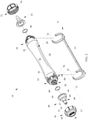
- is an exploded perspective view of the vent filter of
FIG. 1 ; - FIG. 3
- is a side section view of the exemplary vent filter of
FIG. 1 ; - FIG. 4
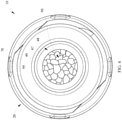
- is an axial end view of an exemplary vent filter;
- FIG. 5
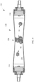
- is a side section view of an alternate embodiment of a vent filter;
- FIG. 6
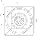
- is an axial end view of an alternate vent filter embodiment;
- FIG. 7
- is an end view of an alternate vent filter embodiment;
- FIG. 8
- is an exploded perspective view of a vent filter with an alternative fitting; and
- FIG. 9
- is a schematic view of the vent filter in fluid communication with a waste tank.
- It is to be understood that the vent filter is not limited in its application to the details of construction and the arrangement of components set forth in the following description or illustrated in the drawings. The invention is capable of other embodiments and of being practiced or of being carried out in various ways. Also, it is to be understood that the phraseology and terminology used herein is for the purpose of description and should not be regarded as limiting. The use of "including," "comprising," or "having" and variations thereof herein is meant to encompass the items listed thereafter and equivalents thereof as well as additional items. Unless limited otherwise, the terms "connected," "coupled," and "mounted," and variations thereof herein are used broadly and encompass direct and indirect connections, couplings, and mountings. In addition, the terms "connected" and "coupled" and variations thereof are not restricted to physical or mechanical connections or couplings.
- Referring now in detail to the drawings, wherein like numerals indicate like elements throughout several views, there are shown in
FIGS. 1-9 , various embodiments of a waste tank vent filter. The waste tank vent filter comprises a housing which is shaped to preclude gaps from forming between the housing walls and the filtration material inside when the housing is arranged in a horizontal orientation for use. - Referring now to
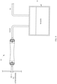
FIG. 1 , a perspective view of a wastetank vent filter 10 is depicted. The wastetank vent filter 10 includes ahousing 20 having afirst end 12 and asecond end 14 which define axial ends of thefilter 10 and agas flowpath 18 therebetween. A filter axis A extends between the first end and thesecond end first end 12 orsecond end 14 may define an inlet and the other of theends FIG. 9 for context, the wastetank vent filter 10 is connected by piping, tubing or other flow structure for fluid communication with awaste tank 16 and scrubs waste gas exiting thewaste tank 16 before the waste gas exits the system to atmosphere. In the embodiment shown inFIG. 9 , the wastetank vent filter 10 is mounted horizontally, according to at least one embodiment, as will be discussed further herein. - Extending from the
first end 12 is a nozzle fitting 40 and oppositely, a second nozzle fitting 42 at thesecond end 14 of the wastetank vent filter 10. Thenozzle fittings housing 20 by acap 50 at thefirst end 12 and acap 52 at thesecond end 14. - The
housing 20 extends between thecaps housing 20 includes afirst housing end 22 and asecond housing end 24. Asidewall 26 defines thehousing 20 between the housing ends 22, 24. Thesidewall 26 is circular in cross-section according to the first embodiment although cross-sectional shapes may be utilized. At the housing ends 22, 24 of thehousing 20, the circular cross-section is of at least a first radius and thehousing 20 has amidpoint 28 which is of a lesser radius than the housing ends 22, 24. As a result, thehousing sidewall 26 is curved along the axial direction between themidpoint 28 and the housing ends 22, 24 or between housing ends 22, 24 and through themidpoint 28. As will be discussed further, the curvature is not the only form of radius reduction which may be utilized. Thehousing 20 may be shaped so as to decrease cross-sectional area alternatively by linear tapering rather than curvature. - The outer housing ends 22, 24 of the
housing 20 have a first radius π as depicted in the figure. Themidpoint 28 comprises a second radius r2 which is less than n. Although the second radius n is depicted at themidpoint 28, the second radius n which may be disposed at various locations other than themidpoint 28 in order to accomplish the goal of creating a neck or area where filtering material is compacted and precludes bypass leakage of odorous air from the waste tank through the wastetank vent filter 10. - The
housing 20 may be formed of various materials. According to one embodiment, thehousing 20 may be formed of a polyethylene, for example a blow molded polyethylene. Other materials may be utilized in order to provide a substantiallyrigid housing 20 which has very limited flexing. The housing ends 22, 24 of thehousing 20 may include grippingaids 30 which are integrally formed. According to the instant embodiment, the gripping aids 30 formed on thehousing 20 is defined by one or more notches or indentations which allow for fingers to grasp thehousing 20. These gripping aids 30 are utilized to hold thehousing 20 still while thecaps FIG. 2 ) in order to retain the vent filter in position. Thebracket 31 may be connected to a wall or other fixed structure and includesfingers 32 which are biased to seat within the grippingaids 30. Thefingers 32 may flex to allow them to be seated within the grippingaids 30. Depending on the orientation of thebracket 31, the wastetank vent filter 10 may be oriented in a horizontal direction according to some embodiments. - Similarly, the
caps cap gripping aids 54 disposed about the circumferential surface of thecaps cap gripping aids 54 are for aid in twisting the caps or endnuts bracket 31. Alternatively, thesecap gripping aids 54 may be notches rather than the ribs as shown. - Referring now to
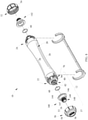
FIG. 2 , an exploded perspective view of the wastetank vent filter 10 is shown. Starting at thefirst end 12 is thecap 50 and the nozzle fitting 40 and o-ring 60. According to the instant embodiment, thecap 50 is generally circular in shape having acap wall 53 from which thecap gripping aids 54 extend. Thecap wall 53 may taper or step down to atop wall 57 having anopening 56. Theopening 56 allows passage of thenozzle top wall 57, thecap wall 53 includes some threads orother connection structure 58. This allows connection tohousing 20. - The
opening 56 is defined by atop wall 57 to allow passage of the nozzle fitting 40, 42. Thecap 50 is attached to thehousing 20 and tightens against thehousing 20 in order to provide a retaining fit for the nozzle fitting 40, 42 on thehousing 20. However, thecap 50 may be removed to remove and replace the filtration center section orhousing 20. - The
nozzle fitting housing end 22 and allows for fluid communication from within thehousing 20 to a pipe or tube which is connected to the nozzle fitting 40, 42. Each nozzle fitting 40, 42 includes aflange 44 and a firstcylindrical cap portion 46 which may have threads along an interior surface or may include a smooth wall upon which the o-ring 60 may engage. Theflange 44 is seated on a surface at thehousing end 22 so that a seal may be created. Alternatively, or in addition, a seal may be created by the o-ring 60 or at another location between thehousing end 22 and thenozzle fitting 40. A connector or threadedportion 48 extends from thecap portion 46. Theconnector 48 is shown as a stepped structure having afirst diameter 47 and asecond diameter 49. Theconnector 48 has at least two steps so that tubes of varying diameters may be connected to the nozzle fitting 42 to provide increased operability of the wastetank vent filter 10. However, alternative embodiments may utilize a tapered connection or other fastening connection. For example, with reference toFIG. 8 ,alternative nozzle fittings nozzle fittings flange 144 and acap portion 146 extending therefrom. One of theflange 144 and thecap portion 146 define a sealing surface along which a seal is formed. For example o-ring 60 may seal along the inner surface ofcap portion 146. Extending from an end ofbody 146, opposite theflange 144, is a threadedportion 148 including at least onethread 149 extending from anend 147 toward thecap portion 146. The threadedportion 148 allows for connection of a garden hose type fitting and hose to provide for venting to atmosphere, rather than a tube. - At the housing end 22 a plurality of threads or
other fastening structures 70 are located. This allows engagement of thecap 50 and capture of the nozzle fitting 40 thereon. Anipple 80 extends from an end surface of thehousing end 22 and provides aflow communication aperture 82 into the interior of thehousing 20. Agroove 84 is located along thenipple 80 to seat the o-ring 60 and allow for engagement with thenozzle fitting 40. - The
fastening structures 70 located at thehousing end 22 may be continuous or may be discontinuous to allow thecap 50 to slide on in an axial direction and be rotated to lock. Alternatively, the surface of thehousing end 22 may include indentions which allow for a male thread on thecap 50 to engage. This structure may be a twist lock or other such feature to allow removal of thecap 50 and replacement of filtering material located within thehousing 20. Further, in some embodiments, thecap 50 may not be removable. - The
opposite housing end 24 of thehousing 20 is similar to thefirst end 22 and therefore, is not discussed for reasons of repetitiveness. - Beneath the
housing 20, thebracket 31 is shown. Thebracket 31 may be fastened to a wall or other static structure and includesfingers 32. Thefingers 32 extend about the housing ends 22, 24 to engagegripping aids 30 with detents at ends of thefingers 32. However this is merely one embodiment and various means may be utilized to retain thehousing 20 in thebracket 31. Thebracket 31 may be mounted in various configurations, but according to one embodiment thebracket 31 is mounted so that anarm 33 is mounted horizontally, wherein thevent filter housing 20 is also mounted horizontally. - Referring now to
FIG. 3 , a side section view of the wastetank vent filter 10 is depicted in an assembled construction. Thehousing 20 includes the nozzle fitting 40, 42 positioned on thenipple 80. Thenozzle fitting ring 60 located ingroove 84 which extends about thenipple 80. Thenozzle fitting housing 20 wherein a plurality offilter material 90 is located. Once thecap 50 is applied over the nozzle fitting 40, 42, the fitting 40, 42 is captured and sealed at thefirst housing end 22 andsecond housing end 24 of thehousing 20. - As shown extending between the
first end 22 and thesecond end 24 of thehousing 20, asidewall 26 is located wherein a first diameter di is disposed at or near the first and second housing ends 22, 24 of thehousing 20. The first and second housing ends 22, 24 may be of equivalent radius or alternatively, may be of differing radiuses. The filtering material may be a carbon filtration particulate, such as for non- limiting example activated carbon. The term "particulate" is meant to include various shapes and sizes of small granular or pelletized filtering material. This may include all of a single size or of particulate of various sizes within one or more ranges. In operation, the particulate or filteringmaterial 90 generally settles downwardly from theupper sidewall 26 due to gravity and over a period of time. However, present embodiment shows that at themidpoint 28 of thehousing 20, a second radius or diameter d2 is less than the first radius di at the first and second housing ends 22, 24. So that the particulate or filteringmaterial 90 does not form a gap with thesidewall 26. The elimination of a gap between thesidewall 26 and thefiltering material 90 at themidpoint 28 necessitates that odorous air passing from a first end to asecond end tank vent filter 10 must pass through thefiltering material 90. As a result, even over a period of time where normal settling occurs, thefiltering material 90 will extend fully between the necked area for example at themidpoint 28 so as to preclude any bypass of odorous air or gas. - As depicted in the figure, a biasing
structure 34 is depicted. According to instant embodiments, the biasingstructure 34 may be formed of a foam material which is squeezed to reduce its volume and inserted through apertures 82 (FIG. 2 ). Upon insertion of the spring or biasingstructure 34, the ends of thehousing 20 are blocked so thatfiltration material 90 cannot escape or leak from thehousing 20. For example, the biasingstructure 34 may be squeezed and inserted at a first end. Next thefiltering material 90 is filled at an opposite end of the housing and asecond biasing structure 34 is inserted to enclose the particulate in thehousing 20. - The biasing
structure 34 applies an axial force to thefiltering material 90. The axial forces cause thefiltering material 90 to be forced toward themidpoint 28 of thehousing 20 from both housing ends 22, 24. This provides that thefiltration material 90 extends to themidpoint 28 where the cross-sectional dimension d2 is decreased. In this midpoint area, the particulate volume is such that its cross-sectional area is at least sized to be equal to the midpoint cross-section and no gaps are formed between thehousing sidewall 26 and thefiltering material 90, even upon settling of thefiltering material 90 over time and when thehousing 20 is in a horizontal configuration. This arrangement ensures that the gases from the waste tank must be filtered and cannot bypass theparticulate filtration material 90. - The biasing
structure 34 may be formed of various materials including but not limited to resilient foams. Metallic springs and other structures may additionally be utilized. Additionally, the biasing structure may take various shapes. For example in some embodiments, the biasing structure may have a circular cross-section. In other embodiments, the spring may have other cross-sectional shapes, such as square, rectangular or other polygons. Further, the cross-sectional shape of the spring need not match the cross-sectional shape of thehousing 20. The biasingstructures 34 may apply force to thefilter material 90 regardless of shape so that thefilter material 90 is urged toward the reduced dimension portion of thehousing 20. - Referring now to
FIG. 4 , an end view is depicted of the wastetank vent filter 10. In this embodiment, the biasingstructure 34 is removed so that thefiltering material 90 may be seen. The threadedportion 48 of the nozzle fitting 42 is shown extending from the housingfirst end 22. The axial end view shows thefiltering material 90 positioned within thehousing 20. As depicted, thefiltering material 90 is fully covering the flow path within thehousing 20 and requiring that the odorous gas pass therethrough. - Referring now to
FIGS. 5 and6 an alternate construction is shown wherein a vent filter 1 10 is depicted having analternate housing construction 120. The housing construction has a decreasing dimension along the axial direction as with the previous embodiment. However, thehousing 120 is tapered in a linear fashion in the depicted embodiment rather than curved. Alternatively, at least onesidewall 126 may be curved as well to change from the outer dimension to the smaller dimension near themidpoint 128 of thehousing 120. The biasingstructure 134 is also shown forcingfiltering material 90 toward themidpoint 128. - As viewed in the axial end view of
FIG. 6 , a furtheralternative vent filter 210 embodiment is depicted wherein thehousing 220 has a square cross-section. Again, the biasingstructure 34 is removed for viewing of thefiltering material 90 therein. The axial end view shows thefiltration material 90 extends entirely across the opening depicted at or near themidpoint 228 of the instant embodiment. With this cross- section, thesidewalls 226 may be linearly tapered or may be curved to the smaller dimension. - Referring to
FIG. 7 , a further alternative embodiment is shown with the biasingstructure 34 removed. Thevent filter 310 has a substantially triangular shapedhousing 320. As depicted, the cross-sectional shape reduces in perimeter along an axial dimension. This may be linearly or curved reduction. However, it should be understood that various profiles may be utilized to create the housing such that the dimension at the ends of thehousing 320 is less than that of the dimension at themidpoint 328 or at some point between the ends. - Additionally, it should be understood that the cross-sectional shape does not need to be consistent across the axial length of the housing. For example, the housing structure may be molded or otherwise formed so that the ends of the housing have at least one cross-sectional shape and the midpoint or other location between the ends where the perimeter dimension is smaller may be of a second cross-sectional shape.
- The filtering material or particulate 90 may comprise an activated carbon to adsorb odors. Adsorption, as opposed to absorption, is when organic molecules bond to the internal pores of the activated carbon. This occurs in pores slightly larger than the molecules that are being adsorbed. The molecules of the waste gas become wrapped in the pores. The volume of carbon needed to remove the odorous gas over time is partially based on filter size, shape and the size of the holding tank and quantity and organic content of the waste water therein. Additionally, environmental factors may affect the amount of activated carbon utilized as well as the time that the carbon will function. The activated carbon may come from various sources including, but not limited to, nut shells, peat, wood, coir, lignite, coal and petroleum pitch. Various processes may be utilized to convert these materials into powder, granules and other physical forms.
Claims (3)
- A vent filter (10) for a waste tank, comprising:a vent filter housing (20) having a first axial end (22) and a second axial end (24);said vent filter housing being defined by a wall (26) which is rigid;a flow path (18) extending between said first axial end (22) and said second axial end (24);said first axial end (22) and said second axial end (24) having at least a first cross-sectional dimension (r1);an intermediate location (28) between said first axial end (22) and said second axial end (24), said intermediate location (28) between said first axial end (22) and said second axial end (24) having a second cross-sectional dimension (r2), said second cross-sectional dimension (r2) being less than said first cross-sectional dimension (r1); anda filter material (90) disposed in said flow path and fully covering said flow path at said intermediate location (28) when the vent filter (10) is mounted in a horizontal position;the vent filter (10) further comprising a first fitting (40) for tubing connection located at said first axial end of said housing (20) and a second fitting (42) for tubing connection located at said second axial end of said housing (20), wherein said first and second fittings (40, 42) are engaged by caps (50, 52),wherein said housing (20) having a curved sidewall (126) between said first axial end (22) and said second axial end (24), orwherein said housing (20) having a linear sidewall extending between said first axial end (22) and said second axial end (24).
- The vent filter (10) of claim 1 further comprising a biasing structure (34) forcing the filter material (90) toward said intermediate location (28) where said second cross-sectional dimension (r2) is reduced.
- The vent filter of (10) claim 1, said caps (50, 52) being removable caps.
Applications Claiming Priority (3)
| Application Number | Priority Date | Filing Date | Title |
|---|---|---|---|
| US14/242,234 US9399183B2 (en) | 2014-04-01 | 2014-04-01 | Vent filter |
| EP15773460.9A EP3126033B1 (en) | 2014-04-01 | 2015-03-30 | Vent filter |
| PCT/US2015/023367 WO2015153473A1 (en) | 2014-04-01 | 2015-03-30 | Vent filter |
Related Parent Applications (2)
| Application Number | Title | Priority Date | Filing Date |
|---|---|---|---|
| EP15773460.9A Division EP3126033B1 (en) | 2014-04-01 | 2015-03-30 | Vent filter |
| EP15773460.9A Division-Into EP3126033B1 (en) | 2014-04-01 | 2015-03-30 | Vent filter |
Publications (2)
| Publication Number | Publication Date |
|---|---|
| EP3456401A1 EP3456401A1 (en) | 2019-03-20 |
| EP3456401B1 true EP3456401B1 (en) | 2022-01-26 |
Family
ID=54188957
Family Applications (2)
| Application Number | Title | Priority Date | Filing Date |
|---|---|---|---|
| EP18202343.2A Active EP3456401B1 (en) | 2014-04-01 | 2015-03-30 | Vent filter |
| EP15773460.9A Active EP3126033B1 (en) | 2014-04-01 | 2015-03-30 | Vent filter |
Family Applications After (1)
| Application Number | Title | Priority Date | Filing Date |
|---|---|---|---|
| EP15773460.9A Active EP3126033B1 (en) | 2014-04-01 | 2015-03-30 | Vent filter |
Country Status (3)
| Country | Link |
|---|---|
| US (1) | US9399183B2 (en) |
| EP (2) | EP3456401B1 (en) |
| WO (1) | WO2015153473A1 (en) |
Families Citing this family (14)
| Publication number | Priority date | Publication date | Assignee | Title |
|---|---|---|---|---|
| US9605627B2 (en) * | 2014-03-31 | 2017-03-28 | K&N Engineering, Inc. | Air filter cleaning wand |
| US10093152B2 (en) | 2014-06-09 | 2018-10-09 | Dometic Sweden Ab | Shrouded roof vent for a vehicle |
| US10400783B1 (en) | 2015-07-01 | 2019-09-03 | Dometic Sweden Ab | Compact fan for a recreational vehicle |
| USD787037S1 (en) | 2015-07-01 | 2017-05-16 | Dometic Sweden Ab | Fan |
| US10076724B2 (en) * | 2016-06-23 | 2018-09-18 | Exxonmobil Research And Engineering Company | Methods and systems for marine sulfur dioxide emission reduction |
| US11027595B2 (en) | 2016-10-13 | 2021-06-08 | Dometic Sweden Ab | Roof fan assembly |
| USD832987S1 (en) | 2016-10-13 | 2018-11-06 | Dometic Sweden Ab | Roof fan shroud |
| USD811562S1 (en) | 2016-11-14 | 2018-02-27 | Dometic Sweden Ab | Toilet |
| US10427081B1 (en) * | 2017-08-11 | 2019-10-01 | Newman IP LLC | Drum vent filter with pressure indicator/stop assembly |
| USD853540S1 (en) | 2017-09-18 | 2019-07-09 | Dometic Sweden Ab | Toilet lid and seat |
| CN112638499A (en) * | 2018-09-07 | 2021-04-09 | 默克专利股份公司 | Breather filter and pure liquid tank |
| CN115353239B (en) * | 2022-09-14 | 2024-06-28 | 江苏永冠给排水设备有限公司 | A new type of suspended light filter water cellar water purifier |
| EP4709504A2 (en) * | 2023-05-10 | 2026-03-18 | Phinia Jersey Holdings LLC | Holding tank filter system |
| US12264640B1 (en) * | 2023-05-18 | 2025-04-01 | Shop 48 LLC | Vapor canister |
Family Cites Families (35)
| Publication number | Priority date | Publication date | Assignee | Title |
|---|---|---|---|---|
| GB603846A (en) | 1943-12-13 | 1948-06-24 | Houdaille Hershey Corp | Improvements in or relating to air cleaners |
| GB609372A (en) | 1946-03-12 | 1948-09-29 | Alfred Minor Goodloe | Improvements in or relating to air filters of the oil bath type |
| NL125713C (en) | 1961-05-29 | 1900-01-01 | ||
| US4322230A (en) | 1980-09-08 | 1982-03-30 | Donaldson Company, Inc. | Unitized gas-particulate filter and housing |
| CA1120131A (en) | 1981-01-09 | 1982-03-16 | Nicholas E. Butts | Subterranean tank leak detection system and method |
| DE3671843D1 (en) | 1985-04-10 | 1990-07-19 | Memtec Ltd | FILTER WITH VARIOUS VOLUME OR CONCENTRATOR. |
| CN1004400B (en) | 1987-01-27 | 1989-06-07 | 东北电力学院 | Media filtration method and apparatus |
| US5139655A (en) * | 1987-08-24 | 1992-08-18 | Sealand Technology, Inc. | Integrated system marine sanitation device |
| US4971477A (en) | 1988-12-22 | 1990-11-20 | Total Containment, Inc. | Secondary contained fluid supply system |
| US5221483A (en) | 1990-06-29 | 1993-06-22 | Coulter Corporation | Process and apparatus for removal of DNA, viruses and endotoxins |
| USD330962S (en) | 1990-07-17 | 1992-11-10 | Maxwell Marine Limited | Winch housing cover |
| US5450975A (en) | 1992-06-26 | 1995-09-19 | Total Containment, Inc. | Secondarily contained underground liquid storage vessel and method of construction |
| DK136192D0 (en) | 1992-11-09 | 1992-11-09 | John Reipur | FILTER |
| DE9313446U1 (en) * | 1993-09-07 | 1993-11-25 | Hagemann, Manfred, 65199 Wiesbaden | Filter cartridge with activated carbon filling for venting faecal cassettes in mobile camping vehicles |
| DE69511227D1 (en) | 1994-12-16 | 1999-09-09 | Vetus Den Ouden N V | Stern screw for a boat |
| US5682919A (en) | 1996-04-01 | 1997-11-04 | American Containment, Inc. | Float controlled valve shut-off assembly |
| US5975132A (en) | 1996-06-25 | 1999-11-02 | Total Containment, Inc. | Preassembled underground secondary containment system for containing fuel |
| US5870871A (en) | 1997-03-04 | 1999-02-16 | Total Containment, Inc. | Sump liner and method of installation |
| US6321726B1 (en) | 2000-06-16 | 2001-11-27 | Visteon Global Technologies, Inc. | Carbon canister spring plate |
| US6708954B2 (en) | 2000-06-16 | 2004-03-23 | Maxwell Marine Limited | Winch |
| EP1322398B2 (en) | 2000-09-19 | 2010-07-28 | Shell Technology Ventures Fund 1 B.V. | A device and a method for filtering a fluid |
| EP1404435A4 (en) | 2001-02-08 | 2006-01-18 | Pall Corp | Purifier |
| GB0411290D0 (en) | 2004-05-20 | 2004-06-23 | Water And Waste Uk Ltd | Fluid filter |
| US7381559B2 (en) | 2004-06-09 | 2008-06-03 | Scientific Plastic Products, Inc. | Fermentation flask for cultivating microorganisms |
| US8449661B2 (en) | 2006-03-29 | 2013-05-28 | Maquet Critical Care Ab | Filter arrangement |
| US20080028734A1 (en) | 2006-08-03 | 2008-02-07 | Mcclain Michael S | Filter assembly |
| NZ549054A (en) | 2006-08-08 | 2009-06-26 | Vetus N V | Chain wheel with a number of chain link pockets |
| NZ549053A (en) | 2006-08-08 | 2009-02-28 | Vetus N V | Rope sheave with faces having opposed ridges |
| FR2905425B1 (en) | 2006-09-04 | 2008-10-17 | Coutier Moulage Gen Ind | WATER DECANTATION BOX FOR AN AIR INTAKE LINE OF AN INTERNAL COMBUSTION ENGINE |
| NZ550867A (en) | 2006-10-26 | 2009-05-31 | Vetus N V | Locking latch handle |
| NL1033185C2 (en) | 2007-01-08 | 2008-12-02 | Vetus Den Ouden N V | Tank. |
| SG168440A1 (en) * | 2009-07-29 | 2011-02-28 | Newform Techart Pte Ltd | Air filter |
| WO2011129729A1 (en) | 2010-04-14 | 2011-10-20 | Camfil Ab | Filter unit for sewage vent pipes |
| CN203154995U (en) * | 2013-04-12 | 2013-08-28 | 贵州东仪医疗器械有限公司 | Gas purification filter |
| DE202013102214U1 (en) | 2013-05-22 | 2013-06-06 | Yit Germany Gmbh | cartridge filters |
-
2014
- 2014-04-01 US US14/242,234 patent/US9399183B2/en active Active
-
2015
- 2015-03-30 EP EP18202343.2A patent/EP3456401B1/en active Active
- 2015-03-30 EP EP15773460.9A patent/EP3126033B1/en active Active
- 2015-03-30 WO PCT/US2015/023367 patent/WO2015153473A1/en not_active Ceased
Non-Patent Citations (1)
| Title |
|---|
| None * |
Also Published As
| Publication number | Publication date |
|---|---|
| EP3456401A1 (en) | 2019-03-20 |
| US9399183B2 (en) | 2016-07-26 |
| EP3126033A4 (en) | 2018-03-28 |
| EP3126033A1 (en) | 2017-02-08 |
| EP3126033B1 (en) | 2020-03-04 |
| WO2015153473A1 (en) | 2015-10-08 |
| US20150273379A1 (en) | 2015-10-01 |
Similar Documents
| Publication | Publication Date | Title |
|---|---|---|
| EP3126033B1 (en) | Vent filter | |
| EP3027879B1 (en) | Vehicle fuel gas pre-filter unit | |
| US7416087B2 (en) | Interiorly disposed filter for portable fuel container | |
| US10076720B2 (en) | Cap with adsorption media | |
| US10035092B2 (en) | Housing, housing cover and connecting part of a device for separating at least one fluid from a gas and a device for the separation of a fluid | |
| US7491258B2 (en) | Fuel tank ventilation device | |
| US20170326482A1 (en) | Systems and apparatus for a fluid filtration device | |
| RU2454589C2 (en) | Tube ventilation system for fuel tank | |
| US20120168028A1 (en) | Oil vapor recovery type fuel dispensing gun | |
| WO2011024253A1 (en) | Filter | |
| US7476269B2 (en) | Evaporative emissions canister suitable for marine use | |
| KR20150131323A (en) | Plunger tube connector for a container for packaging a product, particularly a chemical product | |
| US8887774B2 (en) | Fuel vapor retention system and methods | |
| EP3190278B1 (en) | Vehicle fluid delivery system | |
| US11105301B2 (en) | Pressure regulating device and method for assembling same, for a fuel vapour absorber | |
| US20250196049A1 (en) | Vapor Canister | |
| WO2007083322A3 (en) | New petrol storage tank | |
| WO2024233534A2 (en) | Holding tank filter system | |
| US20180037378A1 (en) | Spring-biased valve assembly | |
| EP1944499A1 (en) | Safety filter | |
| JP2018115579A (en) | Canister and fuel inlet pipe |
Legal Events
| Date | Code | Title | Description |
|---|---|---|---|
| PUAI | Public reference made under article 153(3) epc to a published international application that has entered the european phase |
Free format text: ORIGINAL CODE: 0009012 |
|
| STAA | Information on the status of an ep patent application or granted ep patent |
Free format text: STATUS: THE APPLICATION HAS BEEN PUBLISHED |
|
| AC | Divisional application: reference to earlier application |
Ref document number: 3126033 Country of ref document: EP Kind code of ref document: P |
|
| AK | Designated contracting states |
Kind code of ref document: A1 Designated state(s): AL AT BE BG CH CY CZ DE DK EE ES FI FR GB GR HR HU IE IS IT LI LT LU LV MC MK MT NL NO PL PT RO RS SE SI SK SM TR |
|
| STAA | Information on the status of an ep patent application or granted ep patent |
Free format text: STATUS: REQUEST FOR EXAMINATION WAS MADE |
|
| 17P | Request for examination filed |
Effective date: 20190920 |
|
| RBV | Designated contracting states (corrected) |
Designated state(s): AL AT BE BG CH CY CZ DE DK EE ES FI FR GB GR HR HU IE IS IT LI LT LU LV MC MK MT NL NO PL PT RO RS SE SI SK SM TR |
|
| STAA | Information on the status of an ep patent application or granted ep patent |
Free format text: STATUS: EXAMINATION IS IN PROGRESS |
|
| 17Q | First examination report despatched |
Effective date: 20200429 |
|
| GRAP | Despatch of communication of intention to grant a patent |
Free format text: ORIGINAL CODE: EPIDOSNIGR1 |
|
| STAA | Information on the status of an ep patent application or granted ep patent |
Free format text: STATUS: GRANT OF PATENT IS INTENDED |
|
| INTG | Intention to grant announced |
Effective date: 20210817 |
|
| GRAS | Grant fee paid |
Free format text: ORIGINAL CODE: EPIDOSNIGR3 |
|
| GRAA | (expected) grant |
Free format text: ORIGINAL CODE: 0009210 |
|
| STAA | Information on the status of an ep patent application or granted ep patent |
Free format text: STATUS: THE PATENT HAS BEEN GRANTED |
|
| AC | Divisional application: reference to earlier application |
Ref document number: 3126033 Country of ref document: EP Kind code of ref document: P |
|
| AK | Designated contracting states |
Kind code of ref document: B1 Designated state(s): AL AT BE BG CH CY CZ DE DK EE ES FI FR GB GR HR HU IE IS IT LI LT LU LV MC MK MT NL NO PL PT RO RS SE SI SK SM TR |
|
| REG | Reference to a national code |
Ref country code: GB Ref legal event code: FG4D |
|
| REG | Reference to a national code |
Ref country code: CH Ref legal event code: EP |
|
| REG | Reference to a national code |
Ref country code: AT Ref legal event code: REF Ref document number: 1464808 Country of ref document: AT Kind code of ref document: T Effective date: 20220215 |
|
| REG | Reference to a national code |
Ref country code: IE Ref legal event code: FG4D |
|
| REG | Reference to a national code |
Ref country code: DE Ref legal event code: R096 Ref document number: 602015076752 Country of ref document: DE |
|
| REG | Reference to a national code |
Ref country code: NL Ref legal event code: FP |
|
| REG | Reference to a national code |
Ref country code: LT Ref legal event code: MG9D |
|
| REG | Reference to a national code |
Ref country code: AT Ref legal event code: MK05 Ref document number: 1464808 Country of ref document: AT Kind code of ref document: T Effective date: 20220126 |
|
| PG25 | Lapsed in a contracting state [announced via postgrant information from national office to epo] |
Ref country code: SE Free format text: LAPSE BECAUSE OF FAILURE TO SUBMIT A TRANSLATION OF THE DESCRIPTION OR TO PAY THE FEE WITHIN THE PRESCRIBED TIME-LIMIT Effective date: 20220126 Ref country code: RS Free format text: LAPSE BECAUSE OF FAILURE TO SUBMIT A TRANSLATION OF THE DESCRIPTION OR TO PAY THE FEE WITHIN THE PRESCRIBED TIME-LIMIT Effective date: 20220126 Ref country code: PT Free format text: LAPSE BECAUSE OF FAILURE TO SUBMIT A TRANSLATION OF THE DESCRIPTION OR TO PAY THE FEE WITHIN THE PRESCRIBED TIME-LIMIT Effective date: 20220526 Ref country code: NO Free format text: LAPSE BECAUSE OF FAILURE TO SUBMIT A TRANSLATION OF THE DESCRIPTION OR TO PAY THE FEE WITHIN THE PRESCRIBED TIME-LIMIT Effective date: 20220426 Ref country code: LT Free format text: LAPSE BECAUSE OF FAILURE TO SUBMIT A TRANSLATION OF THE DESCRIPTION OR TO PAY THE FEE WITHIN THE PRESCRIBED TIME-LIMIT Effective date: 20220126 Ref country code: HR Free format text: LAPSE BECAUSE OF FAILURE TO SUBMIT A TRANSLATION OF THE DESCRIPTION OR TO PAY THE FEE WITHIN THE PRESCRIBED TIME-LIMIT Effective date: 20220126 Ref country code: ES Free format text: LAPSE BECAUSE OF FAILURE TO SUBMIT A TRANSLATION OF THE DESCRIPTION OR TO PAY THE FEE WITHIN THE PRESCRIBED TIME-LIMIT Effective date: 20220126 Ref country code: BG Free format text: LAPSE BECAUSE OF FAILURE TO SUBMIT A TRANSLATION OF THE DESCRIPTION OR TO PAY THE FEE WITHIN THE PRESCRIBED TIME-LIMIT Effective date: 20220426 |
|
| PG25 | Lapsed in a contracting state [announced via postgrant information from national office to epo] |
Ref country code: PL Free format text: LAPSE BECAUSE OF FAILURE TO SUBMIT A TRANSLATION OF THE DESCRIPTION OR TO PAY THE FEE WITHIN THE PRESCRIBED TIME-LIMIT Effective date: 20220126 Ref country code: LV Free format text: LAPSE BECAUSE OF FAILURE TO SUBMIT A TRANSLATION OF THE DESCRIPTION OR TO PAY THE FEE WITHIN THE PRESCRIBED TIME-LIMIT Effective date: 20220126 Ref country code: GR Free format text: LAPSE BECAUSE OF FAILURE TO SUBMIT A TRANSLATION OF THE DESCRIPTION OR TO PAY THE FEE WITHIN THE PRESCRIBED TIME-LIMIT Effective date: 20220427 Ref country code: FI Free format text: LAPSE BECAUSE OF FAILURE TO SUBMIT A TRANSLATION OF THE DESCRIPTION OR TO PAY THE FEE WITHIN THE PRESCRIBED TIME-LIMIT Effective date: 20220126 Ref country code: AT Free format text: LAPSE BECAUSE OF FAILURE TO SUBMIT A TRANSLATION OF THE DESCRIPTION OR TO PAY THE FEE WITHIN THE PRESCRIBED TIME-LIMIT Effective date: 20220126 |
|
| PG25 | Lapsed in a contracting state [announced via postgrant information from national office to epo] |
Ref country code: IS Free format text: LAPSE BECAUSE OF FAILURE TO SUBMIT A TRANSLATION OF THE DESCRIPTION OR TO PAY THE FEE WITHIN THE PRESCRIBED TIME-LIMIT Effective date: 20220526 |
|
| REG | Reference to a national code |
Ref country code: DE Ref legal event code: R097 Ref document number: 602015076752 Country of ref document: DE |
|
| PG25 | Lapsed in a contracting state [announced via postgrant information from national office to epo] |
Ref country code: SM Free format text: LAPSE BECAUSE OF FAILURE TO SUBMIT A TRANSLATION OF THE DESCRIPTION OR TO PAY THE FEE WITHIN THE PRESCRIBED TIME-LIMIT Effective date: 20220126 Ref country code: SK Free format text: LAPSE BECAUSE OF FAILURE TO SUBMIT A TRANSLATION OF THE DESCRIPTION OR TO PAY THE FEE WITHIN THE PRESCRIBED TIME-LIMIT Effective date: 20220126 Ref country code: RO Free format text: LAPSE BECAUSE OF FAILURE TO SUBMIT A TRANSLATION OF THE DESCRIPTION OR TO PAY THE FEE WITHIN THE PRESCRIBED TIME-LIMIT Effective date: 20220126 Ref country code: EE Free format text: LAPSE BECAUSE OF FAILURE TO SUBMIT A TRANSLATION OF THE DESCRIPTION OR TO PAY THE FEE WITHIN THE PRESCRIBED TIME-LIMIT Effective date: 20220126 Ref country code: DK Free format text: LAPSE BECAUSE OF FAILURE TO SUBMIT A TRANSLATION OF THE DESCRIPTION OR TO PAY THE FEE WITHIN THE PRESCRIBED TIME-LIMIT Effective date: 20220126 Ref country code: CZ Free format text: LAPSE BECAUSE OF FAILURE TO SUBMIT A TRANSLATION OF THE DESCRIPTION OR TO PAY THE FEE WITHIN THE PRESCRIBED TIME-LIMIT Effective date: 20220126 |
|
| REG | Reference to a national code |
Ref country code: CH Ref legal event code: PL |
|
| PG25 | Lapsed in a contracting state [announced via postgrant information from national office to epo] |
Ref country code: AL Free format text: LAPSE BECAUSE OF FAILURE TO SUBMIT A TRANSLATION OF THE DESCRIPTION OR TO PAY THE FEE WITHIN THE PRESCRIBED TIME-LIMIT Effective date: 20220126 |
|
| PLBE | No opposition filed within time limit |
Free format text: ORIGINAL CODE: 0009261 |
|
| STAA | Information on the status of an ep patent application or granted ep patent |
Free format text: STATUS: NO OPPOSITION FILED WITHIN TIME LIMIT |
|
| REG | Reference to a national code |
Ref country code: BE Ref legal event code: MM Effective date: 20220331 |
|
| 26N | No opposition filed |
Effective date: 20221027 |
|
| PG25 | Lapsed in a contracting state [announced via postgrant information from national office to epo] |
Ref country code: LU Free format text: LAPSE BECAUSE OF NON-PAYMENT OF DUE FEES Effective date: 20220330 Ref country code: LI Free format text: LAPSE BECAUSE OF NON-PAYMENT OF DUE FEES Effective date: 20220331 Ref country code: IE Free format text: LAPSE BECAUSE OF NON-PAYMENT OF DUE FEES Effective date: 20220330 Ref country code: CH Free format text: LAPSE BECAUSE OF NON-PAYMENT OF DUE FEES Effective date: 20220331 |
|
| PG25 | Lapsed in a contracting state [announced via postgrant information from national office to epo] |
Ref country code: SI Free format text: LAPSE BECAUSE OF FAILURE TO SUBMIT A TRANSLATION OF THE DESCRIPTION OR TO PAY THE FEE WITHIN THE PRESCRIBED TIME-LIMIT Effective date: 20220126 Ref country code: BE Free format text: LAPSE BECAUSE OF NON-PAYMENT OF DUE FEES Effective date: 20220331 |
|
| P01 | Opt-out of the competence of the unified patent court (upc) registered |
Effective date: 20230526 |
|
| PG25 | Lapsed in a contracting state [announced via postgrant information from national office to epo] |
Ref country code: HU Free format text: LAPSE BECAUSE OF FAILURE TO SUBMIT A TRANSLATION OF THE DESCRIPTION OR TO PAY THE FEE WITHIN THE PRESCRIBED TIME-LIMIT; INVALID AB INITIO Effective date: 20150330 |
|
| PG25 | Lapsed in a contracting state [announced via postgrant information from national office to epo] |
Ref country code: MK Free format text: LAPSE BECAUSE OF FAILURE TO SUBMIT A TRANSLATION OF THE DESCRIPTION OR TO PAY THE FEE WITHIN THE PRESCRIBED TIME-LIMIT Effective date: 20220126 Ref country code: CY Free format text: LAPSE BECAUSE OF FAILURE TO SUBMIT A TRANSLATION OF THE DESCRIPTION OR TO PAY THE FEE WITHIN THE PRESCRIBED TIME-LIMIT Effective date: 20220126 |
|
| PG25 | Lapsed in a contracting state [announced via postgrant information from national office to epo] |
Ref country code: MC Free format text: LAPSE BECAUSE OF FAILURE TO SUBMIT A TRANSLATION OF THE DESCRIPTION OR TO PAY THE FEE WITHIN THE PRESCRIBED TIME-LIMIT Effective date: 20220331 |
|
| PG25 | Lapsed in a contracting state [announced via postgrant information from national office to epo] |
Ref country code: MC Free format text: LAPSE BECAUSE OF FAILURE TO SUBMIT A TRANSLATION OF THE DESCRIPTION OR TO PAY THE FEE WITHIN THE PRESCRIBED TIME-LIMIT Effective date: 20220331 |
|
| PG25 | Lapsed in a contracting state [announced via postgrant information from national office to epo] |
Ref country code: MT Free format text: LAPSE BECAUSE OF FAILURE TO SUBMIT A TRANSLATION OF THE DESCRIPTION OR TO PAY THE FEE WITHIN THE PRESCRIBED TIME-LIMIT Effective date: 20220126 |
|
| PGFP | Annual fee paid to national office [announced via postgrant information from national office to epo] |
Ref country code: IT Payment date: 20250114 Year of fee payment: 11 |
|
| PG25 | Lapsed in a contracting state [announced via postgrant information from national office to epo] |
Ref country code: TR Free format text: LAPSE BECAUSE OF FAILURE TO SUBMIT A TRANSLATION OF THE DESCRIPTION OR TO PAY THE FEE WITHIN THE PRESCRIBED TIME-LIMIT Effective date: 20220126 |
|
| PGFP | Annual fee paid to national office [announced via postgrant information from national office to epo] |
Ref country code: GB Payment date: 20260310 Year of fee payment: 12 |
|
| PGFP | Annual fee paid to national office [announced via postgrant information from national office to epo] |
Ref country code: DE Payment date: 20260304 Year of fee payment: 12 |
|
| PGFP | Annual fee paid to national office [announced via postgrant information from national office to epo] |
Ref country code: NL Payment date: 20260317 Year of fee payment: 12 |
|
| PGFP | Annual fee paid to national office [announced via postgrant information from national office to epo] |
Ref country code: FR Payment date: 20260312 Year of fee payment: 12 |