EP3456117B1 - Hybrid class b fd-mimo - Google Patents
Hybrid class b fd-mimo Download PDFInfo
- Publication number
- EP3456117B1 EP3456117B1 EP17795552.3A EP17795552A EP3456117B1 EP 3456117 B1 EP3456117 B1 EP 3456117B1 EP 17795552 A EP17795552 A EP 17795552A EP 3456117 B1 EP3456117 B1 EP 3456117B1
- Authority
- EP
- European Patent Office
- Prior art keywords
- csi
- resource
- cell
- beamformed csi
- common
- Prior art date
- Legal status (The legal status is an assumption and is not a legal conclusion. Google has not performed a legal analysis and makes no representation as to the accuracy of the status listed.)
- Active
Links
Images


Classifications
-
- H—ELECTRICITY
- H04—ELECTRIC COMMUNICATION TECHNIQUE
- H04B—TRANSMISSION
- H04B7/00—Radio transmission systems, i.e. using radiation field
- H04B7/02—Diversity systems; Multi-antenna system, i.e. transmission or reception using multiple antennas
- H04B7/04—Diversity systems; Multi-antenna system, i.e. transmission or reception using multiple antennas using two or more spaced independent antennas
- H04B7/0413—MIMO systems
- H04B7/0452—Multi-user MIMO systems
-
- H—ELECTRICITY
- H04—ELECTRIC COMMUNICATION TECHNIQUE
- H04B—TRANSMISSION
- H04B7/00—Radio transmission systems, i.e. using radiation field
- H04B7/02—Diversity systems; Multi-antenna system, i.e. transmission or reception using multiple antennas
- H04B7/04—Diversity systems; Multi-antenna system, i.e. transmission or reception using multiple antennas using two or more spaced independent antennas
- H04B7/0413—MIMO systems
- H04B7/0417—Feedback systems
-
- H—ELECTRICITY
- H04—ELECTRIC COMMUNICATION TECHNIQUE
- H04B—TRANSMISSION
- H04B7/00—Radio transmission systems, i.e. using radiation field
- H04B7/02—Diversity systems; Multi-antenna system, i.e. transmission or reception using multiple antennas
- H04B7/04—Diversity systems; Multi-antenna system, i.e. transmission or reception using multiple antennas using two or more spaced independent antennas
- H04B7/0413—MIMO systems
- H04B7/0456—Selection of precoding matrices or codebooks, e.g. using matrices antenna weighting
-
- H—ELECTRICITY
- H04—ELECTRIC COMMUNICATION TECHNIQUE
- H04B—TRANSMISSION
- H04B7/00—Radio transmission systems, i.e. using radiation field
- H04B7/02—Diversity systems; Multi-antenna system, i.e. transmission or reception using multiple antennas
- H04B7/04—Diversity systems; Multi-antenna system, i.e. transmission or reception using multiple antennas using two or more spaced independent antennas
- H04B7/06—Diversity systems; Multi-antenna system, i.e. transmission or reception using multiple antennas using two or more spaced independent antennas at the transmitting station
- H04B7/0613—Diversity systems; Multi-antenna system, i.e. transmission or reception using multiple antennas using two or more spaced independent antennas at the transmitting station using simultaneous transmission
- H04B7/0615—Diversity systems; Multi-antenna system, i.e. transmission or reception using multiple antennas using two or more spaced independent antennas at the transmitting station using simultaneous transmission of weighted versions of same signal
- H04B7/0617—Diversity systems; Multi-antenna system, i.e. transmission or reception using multiple antennas using two or more spaced independent antennas at the transmitting station using simultaneous transmission of weighted versions of same signal for beam forming
-
- H—ELECTRICITY
- H04—ELECTRIC COMMUNICATION TECHNIQUE
- H04B—TRANSMISSION
- H04B7/00—Radio transmission systems, i.e. using radiation field
- H04B7/02—Diversity systems; Multi-antenna system, i.e. transmission or reception using multiple antennas
- H04B7/04—Diversity systems; Multi-antenna system, i.e. transmission or reception using multiple antennas using two or more spaced independent antennas
- H04B7/06—Diversity systems; Multi-antenna system, i.e. transmission or reception using multiple antennas using two or more spaced independent antennas at the transmitting station
- H04B7/0613—Diversity systems; Multi-antenna system, i.e. transmission or reception using multiple antennas using two or more spaced independent antennas at the transmitting station using simultaneous transmission
- H04B7/0615—Diversity systems; Multi-antenna system, i.e. transmission or reception using multiple antennas using two or more spaced independent antennas at the transmitting station using simultaneous transmission of weighted versions of same signal
- H04B7/0619—Diversity systems; Multi-antenna system, i.e. transmission or reception using multiple antennas using two or more spaced independent antennas at the transmitting station using simultaneous transmission of weighted versions of same signal using feedback from receiving side
- H04B7/0621—Feedback content
- H04B7/0626—Channel coefficients, e.g. channel state information [CSI]
-
- H—ELECTRICITY
- H04—ELECTRIC COMMUNICATION TECHNIQUE
- H04L—TRANSMISSION OF DIGITAL INFORMATION, e.g. TELEGRAPHIC COMMUNICATION
- H04L5/00—Arrangements affording multiple use of the transmission path
- H04L5/0001—Arrangements for dividing the transmission path
- H04L5/0014—Three-dimensional division
- H04L5/0023—Time-frequency-space
-
- H—ELECTRICITY
- H04—ELECTRIC COMMUNICATION TECHNIQUE
- H04L—TRANSMISSION OF DIGITAL INFORMATION, e.g. TELEGRAPHIC COMMUNICATION
- H04L5/00—Arrangements affording multiple use of the transmission path
- H04L5/003—Arrangements for allocating sub-channels of the transmission path
- H04L5/0048—Allocation of pilot signals, i.e. of signals known to the receiver
- H04L5/005—Allocation of pilot signals, i.e. of signals known to the receiver of common pilots, i.e. pilots destined for multiple users or terminals
-
- H—ELECTRICITY
- H04—ELECTRIC COMMUNICATION TECHNIQUE
- H04L—TRANSMISSION OF DIGITAL INFORMATION, e.g. TELEGRAPHIC COMMUNICATION
- H04L5/00—Arrangements affording multiple use of the transmission path
- H04L5/003—Arrangements for allocating sub-channels of the transmission path
- H04L5/0048—Allocation of pilot signals, i.e. of signals known to the receiver
- H04L5/0051—Allocation of pilot signals, i.e. of signals known to the receiver of dedicated pilots, i.e. pilots destined for a single user or terminal
-
- H—ELECTRICITY
- H04—ELECTRIC COMMUNICATION TECHNIQUE
- H04L—TRANSMISSION OF DIGITAL INFORMATION, e.g. TELEGRAPHIC COMMUNICATION
- H04L5/00—Arrangements affording multiple use of the transmission path
- H04L5/003—Arrangements for allocating sub-channels of the transmission path
- H04L5/0053—Allocation of signalling, i.e. of overhead other than pilot signals
- H04L5/0057—Physical resource allocation for CQI
-
- H—ELECTRICITY
- H04—ELECTRIC COMMUNICATION TECHNIQUE
- H04B—TRANSMISSION
- H04B7/00—Radio transmission systems, i.e. using radiation field
- H04B7/02—Diversity systems; Multi-antenna system, i.e. transmission or reception using multiple antennas
- H04B7/04—Diversity systems; Multi-antenna system, i.e. transmission or reception using multiple antennas using two or more spaced independent antennas
- H04B7/06—Diversity systems; Multi-antenna system, i.e. transmission or reception using multiple antennas using two or more spaced independent antennas at the transmitting station
- H04B7/0613—Diversity systems; Multi-antenna system, i.e. transmission or reception using multiple antennas using two or more spaced independent antennas at the transmitting station using simultaneous transmission
- H04B7/0615—Diversity systems; Multi-antenna system, i.e. transmission or reception using multiple antennas using two or more spaced independent antennas at the transmitting station using simultaneous transmission of weighted versions of same signal
- H04B7/0619—Diversity systems; Multi-antenna system, i.e. transmission or reception using multiple antennas using two or more spaced independent antennas at the transmitting station using simultaneous transmission of weighted versions of same signal using feedback from receiving side
- H04B7/0636—Feedback format
- H04B7/0639—Using selective indices, e.g. of a codebook, e.g. pre-distortion matrix index [PMI] or for beam selection
Definitions
- aspects of the present disclosure relate generally to wireless communication systems, and more particularly, to a hybrid beamformed CSI-RS scheme for full dimension multiple input, multiple output (FD-MIMO) systems with a large number of antennas.
- FD-MIMO full dimension multiple input, multiple output
- Wireless communication networks are widely deployed to provide various communication services such as voice, video, packet data, messaging, broadcast, and the like. These wireless networks may be multiple-access networks capable of supporting multiple users by sharing the available network resources. Such networks, which are usually multiple access networks, support communications for multiple users by sharing the available network resources.
- UTRAN Universal Terrestrial Radio Access Network
- the UTRAN is the radio access network (RAN) defined as a part of the Universal Mobile Telecommunications System (UMTS), a third generation (3G) mobile phone technology supported by the 3rd Generation Partnership Project (3GPP).
- UMTS Universal Mobile Telecommunications System
- 3GPP 3rd Generation Partnership Project
- multiple-access network formats include Code Division Multiple Access (CDMA) networks, Time Division Multiple Access (TDMA) networks, Frequency Division Multiple Access (FDMA) networks, Orthogonal FDMA (OFDMA) networks, and Single-Carrier FDMA (SC-FDMA) networks.
- CDMA Code Division Multiple Access
- TDMA Time Division Multiple Access
- FDMA Frequency Division Multiple Access
- OFDMA Orthogonal FDMA
- SC-FDMA Single-Carrier FDMA
- a wireless communication network may include a number of base stations or node Bs that can support communication for a number of user equipments (UEs).
- a UE may communicate with a base station via downlink and uplink.
- the downlink (or forward link) refers to the communication link from the base station to the UE
- the uplink (or reverse link) refers to the communication link from the UE to the base station.
- a base station may transmit data and control information on the downlink to a UE and/or may receive data and control information on the uplink from the UE.
- a transmission from the base station may encounter interference due to transmissions from neighbor base stations or from other wireless radio frequency (RF) transmitters.
- RF radio frequency
- a transmission from the UE may encounter interference from uplink transmissions of other UEs communicating with the neighbor base stations or from other wireless RF transmitters. This interference may degrade performance on both the downlink and uplink.
- US 2014/0044044 A1 discloses methods and apparatus for sending and receiving mobile station (MS) specific channel state indication reference symbols (CSI-RS).
- a common CSI-RS is sent from a base station (BS) and is received by an MS.
- First feedback is sent to the BS from the MS based on the common CSI-RS.
- a configuration of an MS-specific CSI-RS is sent from the BS and received by the MS.
- An MS specific CSI-RS is sent from the BS and is received by the MS.
- Second feedback is sent to the BS from the MS based on the MS specific CSI-RS.
- WO 2014/117748 A1 discloses techniques for a user equipment (UE) to efficiently provide feedback regarding preferred beams to a base station (BS) that transmits with different beams from different elevations.
- the techniques generally involve the BS transmitting first reference signals transmitted, using a plurality of elevation beams.
- the UE selects at least one preferred elevation beam based on the first reference signals and feeds this back to the BS.
- the BS transmits second reference signals using the preferred elevation beam and a plurality of azimuthal ports.
- the UE provides a second stage channel feedback to the base station, based on the second reference signals.
- EP 2 869 478 A1 discloses a method of reporting channel state information (CSI) on a terminal in which a plurality of CSI processes are configured in a wireless communication system, the method comprising measuring a channel based on a CSI reference signal (RS) resource related to one of the CSI processes, measuring interference based on a CSI-interference measurement (IM) resource related to the CSI process, determining CSI based on the measured channel and the measured interference, and reporting the CSI through an uplink channel, wherein a codebook for reporting the CSI, which is used for determining the CSI, is one of two or more codebooks that correspond independently to each of the CSI processes.
- RS CSI reference signal
- IM CSI-interference measurement
- a method of wireless communication at a base station comprising: transmitting (700) a cell-common beamformed channel state information, CSI, reference signal, CSI-RS, resource, wherein the cell-common beamformed CSI-RS resource is weighted by cycling through a set of predefined precoding weights; receiving (701) CSI feedback from at least one user equipment, UE, wherein the CSI feedback is based on the cell-common beamformed CSI-RS resource; and transmitting (702) to the at least one UE a UE-specific beamformed CSI-RS resource, wherein the UE-specific beamformed CSI-RS resource is configured based on the CSI feedback from the at least one UE; wherein the UE-specific beamformed CSI-RS resource is configured using a second precoding weight adapted according to the CSI feedback associated with the cell-common beamformed CSI-RS resource; wherein the configuration of the UE-specific beamformed CSI-RS resource
- an apparatus configured for wireless communication at a base station (105), comprising: means (1400a-t) for transmitting a cell-common beamformed channel state information, CSI, reference signal, CSI-RS, resource, wherein the cell-common beamformed CSI-RS resource is weighted by cycling through a set of predefined precoding weights; means (1400a-t) for receiving CSI feedback from at least one user equipment, UE, wherein the CSI feedback is based on the cell-common beamformed CSI-RS resource; and means (1400a-t) for transmitting to the at least one UE a UE-specific beamformed CSI-RS resource, wherein the UE-specific beamformed CSI-RS resource is configured based on the CSI feedback from the at least one UE; wherein the UE-specific beamformed CSI-RS resource is configured using a second precoding weight adapted according to the CSI feedback associated with the cell-common beamformed CSI-RS resource; wherein
- This disclosure relates generally to providing or participating in authorized shared access between two or more wireless communications systems, also referred to as wireless communications networks.
- the techniques and apparatus may be used for wireless communication networks such as code division multiple access (CDMA) networks, time division multiple access (TDMA) networks, frequency division multiple access (FDMA) networks, orthogonal FDMA (OFDMA) networks, single-carrier FDMA (SC-FDMA) networks, LTE networks, GSM networks, as well as other communications networks.
- CDMA code division multiple access
- TDMA time division multiple access
- FDMA frequency division multiple access
- OFDMA orthogonal FDMA
- SC-FDMA single-carrier FDMA
- a CDMA network may implement a radio technology such as universal terrestrial radio access (UTRA), cdma2000, and the like.
- UTRA includes wideband-CDMA (W-CDMA) and low chip rate (LCR).
- CDMA2000 covers IS-2000, IS-95, and IS-856 standards.
- a TDMA network may implement a radio technology such as Global System for Mobile Communications (GSM).
- GSM Global System for Mobile Communications
- 3GPP defines standards for the GSM EDGE (enhanced data rates for GSM evolution) radio access network (RAN), also denoted as GERAN.
- GERAN is the radio component of GSM/EDGE, together with the network that joins the base stations (for example, the Ater and Abis interfaces) and the base station controllers (A interfaces, etc.).
- the radio access network represents a component of a GSM network, through which phone calls and packet data are routed from and to the public switched telephone network (PSTN) and Internet to and from subscriber handsets, also known as user terminals or user equipments (UEs).
- PSTN public switched telephone network
- UEs subscriber handsets
- a mobile phone operator's network may comprise one or more GERANs, which may be coupled with UTRANs in the case of a UMTS/GSM network.
- An operator network may also include one or more LTE networks, and/or one or more other networks.
- the various different network types may use different radio access technologies (RATs) and radio access networks (RANs).
- RATs radio access technologies
- RANs radio access networks
- An OFDMA network may implement a radio technology such as evolved UTRA (E-UTRA), IEEE 802.11, IEEE 802.16, IEEE 802.20, flash-OFDM and the like.
- E-UTRA evolved UTRA
- GSM Global System for Mobile communications
- LTE long term evolution
- UTRA, E-UTRA, GSM, UMTS and LTE are described in documents provided from an organization named "3rd Generation Partnership Project” (3GPP), and cdma2000 is described in documents from an organization named "3rd Generation Partnership Project 2" (3GPP2).
- 3GPP 3rd Generation Partnership Project
- 3GPP long term evolution LTE
- UMTS universal mobile telecommunications system
- the 3GPP may define specifications for the next generation of mobile networks, mobile systems, and mobile devices.
- LTE terminology may be used as illustrative examples in portions of the description below; however, the description is not intended to be limited to LTE applications.
- the present disclosure is concerned with shared access to wireless spectrum between networks using different radio access technologies or radio air interfaces.
- LTE/LTE-A when operating in unlicensed spectrum, may leverage LTE concepts and may introduce some modifications to physical layer (PHY) and media access control (MAC) aspects of the network or network devices to provide efficient operation in the unlicensed spectrum and meet regulatory requirements.
- the unlicensed spectrum used may range from as low as several hundred Megahertz (MHz) to as high as tens of Gigahertz (GHz), for example.
- LTE/LTE-A networks may operate with any combination of licensed or unlicensed spectrum depending on loading and availability. Accordingly, it may be apparent to one of skill in the art that the systems, apparatus and methods described herein may be applied to other communications systems and applications.
- System designs may support various time-frequency reference signals for the downlink and uplink to facilitate beamforming and other functions.
- a reference signal is a signal generated based on known data and may also be referred to as a pilot, preamble, training signal, sounding signal, and the like.
- a reference signal may be used by a receiver for various purposes such as channel estimation, coherent demodulation, channel quality measurement, signal strength measurement, and the like.
- MIMO systems using multiple antennas generally provide for coordination of sending of reference signals between antennas; however, LTE systems do not in general provide for coordination of sending of reference signals from multiple base stations or eNBs.
- a system may utilize time division duplexing (TDD).
- TDD time division duplexing
- the downlink and uplink share the same frequency spectrum or channel, and downlink and uplink transmissions are sent on the same frequency spectrum.
- the downlink channel response may thus be correlated with the uplink channel response.
- Reciprocity may allow a downlink channel to be estimated based on transmissions sent via the uplink.
- These uplink transmissions may be reference signals or uplink control channels (which may be used as reference symbols after demodulation).
- the uplink transmissions may allow for estimation of a space-selective channel via multiple antennas.
- orthogonal frequency division multiplexing is used for the downlink - that is, from a base station, access point or eNodeB (eNB) to a user terminal or UE.
- OFDM orthogonal frequency division multiplexing
- eNB access point or eNodeB
- Use of OFDM meets the LTE requirement for spectrum flexibility and enables cost-efficient solutions for very wide carriers with high peak rates, and is a well-established technology.
- OFDM is used in standards such as IEEE 802.11a/g, 802.16, High Performance Radio LAN-2 (HIPERLAN-2, wherein LAN stands for Local Area Network) standardized by the European Telecommunications Standards Institute (ETSI), Digital Video Broadcasting (DVB) published by the Joint Technical Committee of ETSI, and other standards.
- ETSI European Telecommunications Standards Institute
- DVD Digital Video Broadcasting
- Time frequency physical resource blocks may be defined in OFDM systems as groups of transport carriers (e.g. sub-carriers) or intervals that are assigned to transport data.
- the RBs are defined over a time and frequency period.
- Resource blocks are comprised of time-frequency resource elements (also denoted here in as resource elements or "REs" for brevity), which may be defined by indices of time and frequency in a slot. Additional details of LTE RBs and REs are described in the 3GPP specifications, such as, for example, 3GPP TS 36.211.
- UMTS LTE supports scalable carrier bandwidths from 20 MHz down to 1.4 MHZ.
- an RB is defined as 12 sub-carriers when the subcarrier bandwidth is 15 kHz, or 24 sub-carriers when the sub-carrier bandwidth is 7.5 kHz.
- in the time domain there is a defined radio frame that is 10 ms long and consists of 10 subframes of 1 millisecond (ms) each. Every subframe consists of 2 slots, where each slot is 0.5 ms.
- the subcarrier spacing in the frequency domain in this case is 15 kHz. Twelve of these subcarriers together (per slot) constitute an RB, so in this implementation one resource block is 180 kHz.
- Six Resource blocks fit in a carrier of 1.4 MHz and 100 resource blocks fit in a carrier of 20 MHz.
- an aspect disclosed herein may be implemented independently of any other aspects and that two or more of these aspects may be combined in various ways.
- an apparatus may be implemented or a method may be practiced using any number of the aspects set forth herein.
- such an apparatus may be implemented or such a method may be practiced using other structure, functionality, or structure and functionality in addition to or other than one or more of the aspects set forth herein.
- a method may be implemented as part of a system, device, apparatus, and/or as instructions stored on a computer readable medium for execution on a processor or computer.
- an aspect may comprise at least one element of a claim.
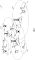
- FIG. 1 shows a wireless network 100 for communication, which may be an LTE-A network.
- the wireless network 100 includes a number of evolved node Bs (eNBs) 105 and other network entities.
- An eNB may be a station that communicates with the UEs and may also be referred to as a base station, a node B, an access point, and the like.
- Each eNB 105 may provide communication coverage for a particular geographic area.
- the term "cell" can refer to this particular geographic coverage area of an eNB and/or an eNB subsystem serving the coverage area, depending on the context in which the term is used.
- An eNB may provide communication coverage for a macro cell or a small cell, such as a pico cell or a femto cell, and/or other types of cell.
- a macro cell generally covers a relatively large geographic area (e.g., several kilometers in radius) and may allow unrestricted access by UEs with service subscriptions with the network provider.
- a small cell, such as a pico cell would generally cover a relatively smaller geographic area and may allow unrestricted access by UEs with service subscriptions with the network provider.
- a small cell such as a femto cell, would also generally cover a relatively small geographic area (e.g., a home) and, in addition to unrestricted access, may also provide restricted access by UEs having an association with the femto cell (e.g., UEs in a closed subscriber group (CSG), UEs for users in the home, and the like).
- An eNB for a macro cell may be referred to as a macro eNB.
- An eNB for a small cell may be referred to as a small cell eNB, a pico eNB, a femto eNB or a home eNB.
- the eNBs 105a, 105b and 105c are macro eNBs for the macro cells 110a, 110b and 110c, respectively.
- the eNBs 105x, 105y, and 105z are small cell eNBs, which may include pico or femto eNBs that provide service to small cells 110x, 110y, and 110z, respectively.
- An eNB may support one or multiple (e.g., two, three, four, and the like) cells.
- the wireless network 100 may support synchronous or asynchronous operation.
- the eNBs may have similar frame timing, and transmissions from different eNBs may be approximately aligned in time.
- the eNBs may have different frame timing, and transmissions from different eNBs may not be aligned in time.
- the UEs 115 are dispersed throughout the wireless network 100, and each UE may be stationary or mobile.
- a UE may also be referred to as a terminal, a mobile station, a subscriber unit, a station, or the like.
- a UE may be a cellular phone, a personal digital assistant (PDA), a wireless modem, a wireless communication device, a handheld device, a tablet computer, a laptop computer, a cordless phone, a wireless local loop (WLL) station, or the like.
- PDA personal digital assistant
- a UE may be able to communicate with macro eNBs, pico eNBs, femto eNBs, relays, and the like.
- a lightning bolt (e.g., communication links 125) indicates wireless transmissions between a UE and a serving eNB, which is an eNB designated to serve the UE on the downlink and/or uplink, or desired transmission between eNBs.
- Wired backhaul communication 134 indicate wired backhaul communications that may occur between eNB s.
- LTE/-A utilizes orthogonal frequency division multiplexing (OFDM) on the downlink and single-carrier frequency division multiplexing (SC-FDM) on the uplink.
- OFDM and SC-FDM partition the system bandwidth into multiple (X) orthogonal subcarriers, which are also commonly referred to as tones, bins, or the like.
- Each subcarrier may be modulated with data.
- modulation symbols are sent in the frequency domain with OFDM and in the time domain with SC-FDM.
- the spacing between adjacent subcarriers may be fixed, and the total number of subcarriers (X) may be dependent on the system bandwidth.
- X may be equal to 72, 180, 300, 600, 900, and 1200 for a corresponding system bandwidth of 1.4, 3, 5, 10, 15, or 20 megahertz (MHz), respectively.
- the system bandwidth may also be partitioned into sub-bands.
- a sub-band may cover 1.08 MHz, and there may be 1, 2, 4, 8 or 16 sub-bands for a corresponding system bandwidth of 1.4, 3, 5, 10, 15, or 20MHz, respectively.
- FIG. 2 shows a block diagram of a design of a base station/eNB 105 and a UE 115, which may be one of the base stations/eNBs and one of the UEs in FIG. 1 .
- the eNB 105 may be the small cell eNB 105z in FIG. 1
- the UE 115 may be the UE 115z, which in order to access small cell eNB 105z, would be included in a list of accessible UEs for small cell eNB 105z.
- the eNB 105 may also be a base station of some other type.
- the eNB 105 may be equipped with antennas 234a through 234t, and the UE 115 may be equipped with antennas 252a through 252r.
- a transmit processor 220 may receive data from a data source 212 and control information from a controller/processor 240.
- the control information may be for the PBCH, PCFICH, PHICH, PDCCH, etc.
- the data may be for the PDSCH, etc.
- the transmit processor 220 may process (e.g., encode and symbol map) the data and control information to obtain data symbols and control symbols, respectively.
- the transmit processor 220 may also generate reference symbols, e.g., for the PSS, SSS, and cell-specific reference signal.
- a transmit (TX) multiple-input multiple-output (MIMO) processor 230 may perform spatial processing (e.g., precoding) on the data symbols, the control symbols, and/or the reference symbols, if applicable, and may provide output symbol streams to the modulators (MODs) 232a through 232t.
- Each modulator 232 may process a respective output symbol stream (e.g., for OFDM, etc.) to obtain an output sample stream.
- Each modulator 232 may further process (e.g., convert to analog, amplify, filter, and upconvert) the output sample stream to obtain a downlink signal.
- Downlink signals from modulators 232a through 232t may be transmitted via the antennas 234a through 234t, respectively.
- the antennas 252a through 252r may receive the downlink signals from the eNB 105 and may provide received signals to the demodulators (DEMODs) 254a through 254r, respectively.
- Each demodulator 254 may condition (e.g., filter, amplify, downconvert, and digitize) a respective received signal to obtain input samples.
- Each demodulator 254 may further process the input samples (e.g., for OFDM, etc.) to obtain received symbols.
- a MIMO detector 256 may obtain received symbols from all the demodulators 254a through 254r, perform MIMO detection on the received symbols if applicable, and provide detected symbols.
- a receive processor 258 may process (e.g., demodulate, deinterleave, and decode) the detected symbols, provide decoded data for the UE 115 to a data sink 260, and provide decoded control information to a controller/processor 280.
- a transmit processor 264 may receive and process data (e.g., for the PUSCH) from a data source 262 and control information (e.g., for the PUCCH) from the controller/processor 280.
- the transmit processor 264 may also generate reference symbols for a reference signal.
- the symbols from the transmit processor 264 may be precoded by a TX MIMO processor 266 if applicable, further processed by the modulators 254a through 254r (e.g., for SC-FDM, etc.), and transmitted to the eNB 105.
- the uplink signals from the UE 115 may be received by the antennas 234, processed by the demodulators 232, detected by a MIMO detector 236 if applicable, and further processed by a receive processor 238 to obtain decoded data and control information sent by the UE 115.
- the processor 238 may provide the decoded data to a data sink 239 and the decoded control information to the controller/processor 240.
- the controllers/processors 240 and 280 may direct the operation at the eNB 105 and the UE 115, respectively.
- the controller/processor 240 and/or other processors and modules at the eNB 105 may perform or direct the execution of various processes for the techniques described herein.
- the controllers/processor 280 and/or other processors and modules at the UE 115 may also perform or direct the execution of the functional blocks illustrated in FIGs. 7 , 9A , 9B , and 11 , and/or other processes for the techniques described herein.
- the memories 242 and 282 may store data and program codes for the eNB 105 and the UE 115, respectively.
- a scheduler 244 may schedule UEs for data transmission on the downlink and/or uplink.
- MIMO Multiple-input multiple-output
- An eNB may broadcast cell-specific CSI reference signals (CSI-RS) for which the UE measures CSI based on configurations signaled by eNB via RRC, such as CSI-RS resource configuration and transmission mode.
- the CSI-RS are periodically transmitted at periodicities of 5, 10, 20, 40, 80 ms, or the like.
- a UE may report CSI at CSI reporting instances also configured by the eNB.
- the UE As a part of CSI reporting the UE generates and reports channel quality indicator (CQI), precoding matrix indicator (PMI), and rank indicator (RI).
- CQI channel quality indicator
- PMI precoding matrix indicator
- RI rank indicator
- the CSI can be reported either via PUCCH or via PUSCH and may be reported either periodically or aperiodically, with potentially different granularity.
- the payload size for CSI may be limited.
- FD-MIMO technology In order to increase system capacity, full-dimensional (FD)-MIMO technology has been considered, in which an eNB uses a two-dimensional (2D) active antenna array with a large number of antennas with antenna ports having both horizontal and vertical axes, and has a larger number of transceiver units.
- 2D two-dimensional
- beamforming has typically implemented using only azimuth dimension, although of a 3D multi-path propagation.
- each transceiver unit has its own independent amplitude and phase control.
- Such capability together with the 2D active antenna array allows the transmitted signal to be steered not only in the horizontal direction, as in conventional multi-antenna systems, but also simultaneously in both the horizontal and the vertical direction, which provides more flexibility in shaping beam directions from an eNB to a UE.
- Providing dynamic beam steering in the vertical direction has been shown to result in significant gain in interference avoidance.
- FD-MIMO technologies may take advantage of both azimuth and elevation beamforming, which would greatly improve MIMO system capacity and signal quality.
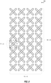
- FIG. 3 is a block diagram illustrating a typical 2D active antenna array 30.
- the CSI in terms of PMI, RI, and CQI. can be fed back to the base station by a mobile station based on downlink channel estimation and predefined PMI codebook(s).
- PMI power of the Physical channels
- RI index of the Physical channels
- CQI CQI codebook
- the eNB capable of FD-MIMO is typically equipped with a large scale antenna system and, thus, the acquisition of full array CSI from the UE is quite challenging due to the complexity of channel estimation and both excessive downlink CSI-RS overhead and uplink CSI feedback overhead.
- FIG. 4A is a block diagram illustrating an example base station 400 transmitting non-precoded CSI-RS 401.
- class A non-precoded reporting one non-zero power (NZP) CSI-RS resource per CSI process may be used for channel measurement in which the number of CSI-RS ports may be 8, 12, or 16.
- NZP non-zero power
- This category includes schemes where different CSI-RS ports may have the same wide beam width and direction and, hence, generally are useful in cell wide coverage.
- Interference measurement in class A reporting may include one CSI-interference measurement (IM) resource per CSI process.
- the UE may report rank indicator, and CQI, as well as PMI, which consists of a first PMI corresponding to the parameters ( i 11 , i 12 ) and one or multiple second PMI corresponding to the parameter, i 2 .
- Base station 400 serves UEs 403 and 404 and UEs 405 and 406 in structure 40.
- 2D CSI-RS ports transmit non-precoded CSI-RS 401 and PDSCH 402 to UEs 403-406.
- UEs 403-406 measure the non-precoded CSI-RS and reports CQI, first PMI ( i 11 , i 12 ) and second PMI, i 2 , (2D codebook), and rank indicator to base station 400.
- FIG. 4B is a block diagram illustrating an example base station 407 transmitting beamformed CSI-RS using CSI-RS resources 408-410.
- CSI-RS resources 408-410 may be directed to serve different UE groups, such as UE group 415, including UEs 411 and 412, and UE group 416, including UEs 413 and 414 in structure 41. Because different CSI-RS resources are used for different UE groups, when providing CSI feedback, UEs 411-414 report CQI, PMI (ID codebook), rank indicator, as well as the CSI-RS resource indicator (CRI), if K > 1, which identifies to base station 407 which of the CSI-RS resources the UE has measured and provided CSI feedback for.
- CQI CQI
- PMI ID codebook
- rank indicator CSI-RS resource indicator
- each CSI process may be associated with K NZP CSI-RS resources/configurations, with N k ports for the k th CSI-RS resource ( K could be ⁇ 1), in which N k may be 1, 2, 4, or 8, and may be different for each CSI-RS resource.
- Each CSI-RS resource may also have different CSI-RS port virtualization, e.g., virtualized from different sets of antenna elements or from the same set of antenna elements but with different beamforming weights. This category includes schemes where, at least at a given time/frequency, CSI-RS ports have narrow beam widths and, hence, would be generally less suitable for cell wide coverage. Some of the CSI-RS port resource combinations may have different beam directions. Multiple CSI-IM per CSI process is also possible, with one-to-one linkage to each NZP CSI-RS resource.
- a UE For a class B enhanced MIMO (eMIMO)-type beamformed CSI-RS with K>1 CSI-RS resources, a UE would report a wideband CRI (CSI-RS resource indicator) and the CQI/PMI/RI for the selected CSI-RS resource identified by the reported CRI. If the number of antenna ports of the selected CSI-RS resource is 4 or 8, then the PMI feedback may include a first PMI i 1 and one or multiple second PMI i 2 .
- K max The maximum number of CSI-RS resources associated with a CSI process, depends on the UE capability. Current UE capabilities support K max of 1...8.
- CQI/PMI/RI is reported based on whether the alternative codebook defined for class B CSI-RS is activated. If the alternative codebook is activated, the first PMI i 1 may be fixed to zero and only the second PMI, i 2 , is reported. The associated W 2 codebook may be used for port pair selection and polarization co-phasing. Otherwise, the reported PMI may include a first PMI and one or multiple second PMI for 4 or 8 antenna ports.
- a hybrid CSI-RS operation has been defined that targets joint utilization of different CSI-RS types, such as between NP CSI-RS and BF CSI-RS, as well as between different types of beamformed CSI-RS.
- CSI reporting for hybrid CSI-RS is performed in two stages. In a first stage of CSI reporting, a long-term CSI, measured on either NP CSI-RS or cell-common beamformed CSI-RS, is reported to an eNB. In the second stage of CSI reporting, the UE measures beamformed CSI-RS precoded based on the first stage CSI report and reports short term CSI feedback, including RI/PMI/CQI.
- Hybrid CSI-RS based FD-MIMO has the benefit of reducing CSI-RS overhead and UE complexity in order to improve FD-MIMO performance.
- Table 1 below identifies possible combinations for hybrid CSI-RS that have been proposed for implementation.
- Table 1 First eMIMO-Type Second eMIMO-Type eMIMO-Type CSI Reporting Content eMIMO-Type CSI Reporting Content Class A ( i 1 , RI) or ( i 1 )
- Class B K 2 1 (RI, CQI, PMI)
- Class B K 1 1 PMI Class B K 2 >1 (RI, CQI, PMI)
- the total CSI-RS overhead may be reduced compared to Rel-13 class B K>1 because the transmission of the second stage CSI-RS can be adapted based on the CRI feedback from the UE, e.g., not all to be transmitted.
- UE complexity may not be reduced as the UE would still be configured to measure multiple CSI-RS resources for first stage CSI feedback, though the measurement would be less frequently.
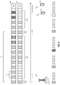
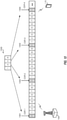
- FIG. 5 is a block diagram illustrating transmission stream 50 with Rel-13 class B K>1 CSI-RS operations.
- K 3 sets of CSI-RS resources (NZP CSI-RS 1, NZP CSI-RS 2, NZP CSI-RS 3) are transmitted at a periodicity, P , e.g., every 5 ms.
- P a periodicity
- First stage CSI-RS 600 includes three resources (NZP CSI-RS 1, NZP CSI-RS 2, NZP CSI-RS 3) transmitted every 20 ms and second stage CSI-RS 601 can be dynamically assigned according to CRI feedback.
- CSI reporting overhead is reduced by performing CRI reporting every 20 ms instead of every 5 ms.
- the CSI processing envelope varies greatly due to the measurement of K>1 CSI-RS resources for CRI reporting at the first stage CSI feedback.
- the eNB would dynamically configure a subset of CSI-RS resources from the resource pool based on the change of the UE's position.
- UEs do not currently support information to assist reconfiguration. If the muted CSI-RS resources of the second stage are reused for data transmission, the dynamic indication of PDSCH rate matching pattern would operate to support all the combinations.
- the current specifications define support for up to four PDSCH rate matching states.
- puncturing will result when colliding with the second stage CSI-RS transmissions which will result in a diminished performance.
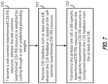
- FIG. 7 is a block diagram illustrating example blocks executed to implement one aspect of the present disclosure, as covered by the present invention. .
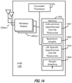
- the example blocks will also be described with respect to eNB 105 as illustrated in FIG. 14.
- FIG. 14 is a block diagram illustrating eNB 105 configured according to one aspect of the present disclosure, as covered by the present invention.
- eNB 105 includes the structure, hardware, and components as illustrated for eNB 105 of FIG. 2 .
- eNB 105 includes controller/processor 240, which operates to execute logic or computer instructions stored in memory 242, as well as controlling the components of eNB 105 that provide the features and functionality of eNB 105.
- eNB 105 under control of controller/processor 240, transmits and receives signals via wireless radios 1400a-t and antennas 234a-t.
- Wireless radios 1400a-t includes various components and hardware, as illustrated in FIG. 2 for eNB 105, including modulator/demodulators 232a-t, MIMO detector 236, receive processor 238, transmit processor 220, and TX MIMO processor 230.
- an eNB transmits a cell-common beamformed CSI-RS resource, wherein the cell-common beamformed CSI-RS resource is weighted by cycling through a set of predefined precoding weights.
- the cell-common beamformed CSI-RS resource may be beamformed using one of a set of predefined precoding weights per each transmission instance common to all UEs within the cell, transmitted at a longer periodicity, and shared by all the UEs in the cell.
- eNB 105 under control of controller/processor 240 executes cell-common beamformed CSI-RS 1401 in memory 242 to form the cell-common beamformed CSI-RS resource using also beamforming weights 1402 stored in memory 242.
- the beamforming of the cell-common beamformed CSI-RS resource may be cycled over a set of predefined weights at beamforming weights 1402 and transparent to UE.
- the eNB receives CSI feedback from at least one UE, wherein the CSI feedback is based on the cell-common beamformed CSI-RS resource.
- eNB 105 under control of controller/processor 240, receives the CSI feedback over antennas 234a-t and wireless radios 1400a-t for processing.
- a UE may report full or partial CSI.
- a full CSI may include RI/PMI/CQI
- a partial CSI includes at least RI (for N k >1) and wideband CQI of the first codeword, and, optionally, a first PMI.
- the RI, if any, and wideband CQI may provide a quality indication for the associated cell-common beamformed CSI-RS resource and may also assist eNB 105 to determine the beamforming weights for the UE-specific beamformed CSI-RS resource.
- a partial CSI may include a wideband CQI of the first codeword, a differential CQI of the second codeword, and optional a first PMI.
- the RI and the second PMI are not reported for the partial CSI. If the UE selects rank 1, the CQI for the second codeword can be set to the index 0 corresponding to a value of out-of-range.
- a new CSI may be defined, such as CSI-RS reference signal receive power (RSRP), and used to assist the eNB for beam selection.
- RSRP CSI-RS reference signal receive power
- the eNB transmits to the at least one UE a UE-specific beamformed CSI-RS resource, wherein the UE-specific beamformed CSI-RS resource is configured based on the CSI feedback from the at least one UE.
- eNB 105 under control of controller/processor 240, executes UE-specific beamformed CSI-RS 1403 stored in memory 242, to generate the UE-specific beamformed CSI-RS resource according to the feedback received from the UE based on the cell-common beamformed CSI-RS resource.
- the UE-specific beamformed CSI-RS resource is transmitted at a short periodicity, and can be turned off and on dynamically to allow resource sharing among multiple UEs.
- Both resources can be configured with different parameter sets, such as number of ports, codebook type, resource element (RE) location, and CSI reporting parameters including reporting modes, periodicity, and subframe offset.
- the UE In response to the UE-specific beamformed CSI-RS resource, the UE would report a full CSI (RI/PMI/CQI), in which the PMI would include only the second PMI if the alternative class B codebook is configured.
- FIG. 8 is a block diagram illustrating an eNB 105 and UEs 115a and 115b configured according to one aspect of the present disclosure.
- Transmission streams 800 and 801 illustrate an example set of transmissions between eNB 105 and UEs 115a and 115b of cell-common and UE-specific beamformed CSI-RS resources.
- NZP CSI-RS #1 802 are cell-common beamformed CSI-RS resources, transmitted periodically at P 1 over transmission streams 800 and 801 between eNB 105 and UEs 115a and 115b.
- the precoding weight for NZP CSI-RS #1 802 may be changed at every transmission instance, by cycling through a set of semi-static precoding weights (B 1 , B 2 , ... B K ).
- NZP CSI-RS #2 803 are UE-specific beamformed CSI-RS resources transmitted periodically at P 2 over transmission streams 800 and 801 between eNB 105 and UEs 115a and 115b.
- the precoding weights (A 1 , A 2 , ..., A K ) and (C 1 , C 2 , ..., C K ) for NZP CSI-RS #2 803 are adapted according to feedback, and may or may not be same as the cell-common precoding weight B k or also the previous weights A k-1 for NZP CSI-RS #2 803 over transmission stream 800 or C k-1 for NZP CSI-RS #2 803 over transmission stream 801.
- Transmissions of UE-specific beamformed CSI-RS resources by eNB 105 over transmission streams 800 and 801 may be muted in order to reduce interference on the transmissions in the other transmission stream.
- NZP CSI-RS #2 803 illustrated with precoding weights A 1 , A 2 , and A 3 over transmission stream 800 between eNB 105 and UE 115a occur while NZP CSI-RS #2 803 transmissions over transmission stream 801 are muted.
- the CQI reported by UE 115a and 115b associated with the cell-common beamformed CSI-RS resources, NZP CSI-RS #1 802, can be used by eNB 105 to determine the precoding weights for the UE-specific beamformed CSI-RS resources, NZP CSI-RS #2 803.
- the UE-specific beamforming weight may be selected according to various alternative aspects, as implemented through execution by eNB 105, under control of controller/processor 240, of weight adapting 1404.
- the execution environment of weight adapting 1404 determines how to adapt the weighting for the UE-specific beamformed CSI-RS.
- FIG. 9A is a block diagram illustrating example blocks executed to implement one aspect of the present disclosure.
- an eNB compares a predetermined number of received CSI reports associated with the predetermined number of precoding weights for the cell-common beamformed CSI-RS resource..
- eNB 105 compares the last K CSI reports (e.g., RI/CQI) associated with K different precoding weights under control of controller/processor 240.
- the eNB selects a largest CSI report of the predetermined number of received CSI reports. For example, eNB 105 selects the CSI report with the largest CSI (e.g., RI and CQI) reported through the execution environment of weight adapting 1404.
- the eNB uses the precoding weight associated with the selected largest CSI report as the second precoding weight for the UE-specific beamformed CSI-RS resource. For example, eNB 105 uses the weight associated with the largest CSI to precode the UE-specific beamformed CSI-RS resources. In such case, the precoding weight for UE-specific beamformed CSI-RS resources may be updated every K reporting cycles.
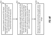
- FIG. 9B is a block diagram illustrating example blocks executed to implement one aspect of the present disclosure, as covered by the present invention.
- an eNB compares a latest received CSI report associated with the cell-common beamformed CSI-RS resource with a latest received CSI report associated with the UE-specific beamformed CSI-RS resource.
- eNB 105 compares the CSI with the latest CSI report from UE-specific beamformed CSI-RS resources via the execution environment of weight adapting 1404.
- the eNB assigns a precoding weight associated with the latest received CSI report for the cell-common beamformed CSI-RS resource as the second precoding weight when difference between the CSI reports of the cell-common and UE-specific beamformed CSI-RS is within a predetermined range. For example, if the CSI reports for the cell-common and UE-specific beamformed CSI-RS resources are on the same level and within the predetermined range, eNB 105 may adapt the UE-specific beamforming weight through the execution environment of weight adapting 1404 using the precoding weight of beamforming weight 1402 associated with the latest CSI report for the cell-common BF CSI-RS.
- the eNB maintains the second precoding weight when the difference falls out of the predetermined range. For example, when the difference between the CSI reports for the cell-common and UE-specific beamformed CSI-RS resources falls outside of the predetermined range, eNB 105, through operation of weight adapting 1404, executed under control of controller/processor 240, would maintain the current precoding weights assigned to the UE-specific beamformed CSI-RS resources. If the first PMI is also reported for the cell-common beamformed CSI-RS, the precoding weight for the UE-specific beamformed CSI-RS resource may be a product of the precoding weight B k associated with the cell-common beamformed CSI-RS and the precoding matrix associated with the reported first PMI.
- FIG. 10A is a block diagram illustrating an eNB 105 configured according to one aspect of the present disclosure.
- transmission pattern 1000 from eNB 105 there may be multiple cell-common beamformed CSI-RS resources in the cell with only one of the cell-common beamformed CSI-RS resources are configured for CSI reporting for each UE.
- Each resource will be associated with a different set of beams which are TDM transmitted using the same resource.
- cell-common beamformed CSI-RS resource #1 1001 may be associated with beams precoded with B 1 -B 4
- cell-common beamformed CSI-RS resource #2 1002 may be associated with beams precoded with B 5 -B 8 .
- Different resources may be associated with different sets of beams corresponding to different coverages which may also be assigned to different groups of UEs.
- Reconfiguration of cell-common beamformed CSI-RS resources may be triggered based on the movement of the UE in the cell.
- Either layer 1 or RRC signaling may be used to signal the reconfiguration of beam sets.
- layer 1 reconfiguration signals triggered measurement of one of multiple CSI-RS configurations.
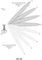
- FIG. 10B is a block diagram illustrating an eNB 105 configured according to one aspect of the present disclosure.
- eNB 105 may also provide multi-stage cell-common beamformed CSI-RS resources for the first CSI feedback that may also reduce beam sweeping round trip time by using a smaller number of beams associated with a cell-common beamformed CSI-RS resource.
- the root CSI-RS resource, cell-common beamformed CSI-RS resource #1 from eNB 106 may be associated with four coarse beams, A-D, providing wide cell coverage.
- the four coarse beams, A-D are TDM swept on the root CSI-RS resource, cell-common beamformed CSI-RS resource #1.
- Each of coarse beam A-D can further be divided into four finer beams, beams #2, #3, #4, and #5, with the same coverage as the associated coarse beam A-D. Therefore, there are sixteen finer beams shown in FIG. 10B .
- Each of the four finer beams, beams #2, #3, #4, and #5 may be TDM swept and assigned to one CSI-RS resource over time. Accordingly, there are four second-level CSI-RS resources.
- each of the sixteen finer beams can further be divided into four finer beams (not shown in FIG. 10B ) to create sixty-four finer beams in a third level. Correspondingly, there would be sixteen third-level CSI-RS resources.
- Each of the sixteen finer beams can further be divided into finer beams in a fourth level, fifth level, sixth level, and so on.
- the network may firstly configure the root or first level CSI-RS resource for UE for coarse beam tracking, then one of four second-level CSI-RS resources for finer beam tracking, then one of sixteen third-level CSI-RS resources for much finer beam tracking, and so on.
- a final UE-specific beamformed CSI-RS resource may be configured for CSI reporting.
- Beam splitting for each of finer beams #2, #3, #4, and #5 may also be possible in order to increase beam granularity.
- the network may first configure the root CSI-RS resource, cell-common beamformed CSI-RS resource #1, for UE measurement and then, based on the CSI feedback, reconfigure a second level CSI-RS resource for the finer beam selection of beams #2, #3, #4, and #5.
- the network may dynamically reconfigure between the coarse and finer CSI-RS resources for UE-specific beam selection based on the received CSI feedback.
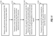
- FIG. 11 is a block diagram illustrating example blocks executed to implement one aspect of the present disclosure. The example blocks will also be described with respect to UE 115 as illustrated in FIG. 15.
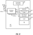
- FIG. 15 is a block diagram illustrating UE 115 configured according to one aspect of the present disclosure.
- UE 115 includes the structure, hardware, and components as illustrated for UE 115 of FIG. 2 .
- controller/processor 280 which operates to execute logic or computer instructions stored in memory 282, as well as controlling the components of UE 115 that provide the features and functionality of UE 115.
- UE 115 under control of controller/processor 280, transmits and receives signals via wireless radios 1500a-t and antennas 252a-r.
- Wireless radios 1500a-t includes various components and hardware, as illustrated in FIG. 2 for eNB 105, including modulator/demodulators 254a-r, MIMO detector 256, receive processor 258, transmit processor 264, and TX MIMO processor 266.
- a UE detects a cell-common beamformed CSI-RS resource from a serving base station. For example, UE 115 detects the cell-common beamformed CSI-RS resource via antennas 252a-r and wireless radios 1500a-r, under control of controller/processor 280.
- the UE transmits a first CSI report based on measurements of the cell-common beamformed CSI-RS resource.
- UE 115 triggers measurement logic 1501, stored in memory 282, and executed by controller/processor 280 to measure CSI of the cell-common beamformed CSI-RS resource.
- the resulting CSI report is generated through execution of CSI report generator 1502, under control of controller/processor 280.
- UE 115 will then transmit the CSI reports over mobile radios 1500a-r and antennas 252a-r.
- the UE receives a UE-specific beamformed CSI-RS resource from the serving base station, wherein the UE-specific beamformed CSI-RS resource is configured based on the first CSI report.
- UE 115 detects the UE-specific beamformed CSI-RS resource via antennas 252a-r and wireless radios 1500a-r, under control of controller/processor 280.
- UE 115 would again execute measurement logic 1501 in memory 282, under control of controller/processor 280.
- the UE transmits a second CSI report based on measurements of the UE-specific beamformed CSI-RS resource.
- controller/processor 280 UE 115 transmits the CSI report generated by execution of CSI report generator 1502 via mobile radios 1500a-r and antennas 252a-r.
- FIG. 12 is a block diagram illustrating an eNB 115 and a UE 105 configured according to one aspect of the present disclosure.
- Various aspects of the present disclosure are provided to further relax CSI computation so that UE 105 computes one CSI corresponding to either the cell-common or UE-specific beamformed CSI-RS resources at a given time period.
- an A-CSI trigger will request a single CSI reporting according to the following rule. If both the UE-specific and cell-common beamformed CSI-RS resources are transmitted on the same subframe, the cell-common beamformed CSI-RS resource may be used for A-CSI reporting.
- the one transmitted earlier may be used for CSI reporting, otherwise the later one is used.
- a and B are one of the UE-specific beamformed CSI-RS resource or the cell-common beamformed CSI-RS resource.
- K may either be fixed to a certain time, such as 5 ms, or it may be configured bia higher layer signaling, e.g., equal to CQI reporting periodicity.
- eNB 105 transmits UE-specific beamformed CSI-RS resource 1200 at subframes 0 and 5. At subframe 7, eNB 105 transmits the cell-common beamformed CSI-RS resource 1201. UE 115 begins sending CSI reports for the detected CSI-RS resources at subframe n + 4 after receiving the CSI-RS resource at subframe n . Thus, after UE-specific beamformed CSI-RS resource 1200 at subframe 0, UE 115 begins transmitting CSI reports based on the UE-specific beamformed CSI-RS resource 1200 at subframe 4. UE 115 continues transmitting the CSI report until the next CSI report associated with the next UE-specific beamformed CSI-RS resource 1200 at subframe 1200.
- UE 115 After receiving cell-common beamformed CSI-RS resource 1201 at subframe 7, UE 115 will not begin transmitting CSI based on the cell-common beamformed CSI-RS resource 1201 at subframe 1 as the time between receiving the previous UE-specific beamformed CSI-RS resource 1200 at subframe 5 and subframe 7 is less than K. Similarly, at receipt of the next UE-specific beamformed CSI-RS resource 1200 at subframe 0 according to the difference between the time of subframe 7 and next frame subframe 0 is again less than K. UE 115 will then begin transmitting CSI reports associated with cell-common beamformed CSI-RS resource 1201 at subframe 4.
- a partial CSI may be reported for a cell-common beamformed CSI-RS resource.
- the partial CSI report may include an RI (max 3-bits), wideband CQI of the first codeword (4-bits), and an optional 4-bits for a first PMI.
- the partial CSI report may include a 4-bit wideband CQI of the first codeword, a 3-bit differential CQI of the second codeword, and an optional 4-bit first PMI.
- the partial PMI whether implemented in either option, will be reported in one subframe with a total maximum payload of 11 bits.
- the reporting periodicity can be independently configured using the same subframe offset as the CQI feedback for UE-specific beamformed CSI-RS resource. If UE-specific beamformed CSI-RS resource is activated, UE may transmit P-CSI reporting for UE-specific beamformed CSI-RS resource the same as the legacy operations, and a periodic CSI may consist of multiple reports based on the reporting mode, for example, wideband or subband, and the configured parameter for the alternative codebook. With the alternative codebook configured, under PUCCH mode 1-1, the first report may be an RI, while the second report is wideband CQI/PMI.
- the first report may be RI, while the second report may be wideband CQI/PMI, and the third report may be subband CQI/PMI.
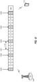
- FIG. 13 is a block diagram illustrating an eNB 105 and a UE 115 configured according to one aspect of the present disclosure.
- CSR codebook subset restrictions
- UE 115 would store the CSR in memory 181 at CSR 1503. In such a manner, the selection of CSI-RS resources is based on the spectrum efficiency taking into account inter-cell interference.
- the k-th CSR is used for the transmission instance satisfying (10 ⁇ n f +floor(n s /2) - ⁇ - k ⁇ T) mod (K ⁇ T), where n f and n s are radio frame number and slot number, K is the number of the configured CSR parameters, and k is a range from 0 to K-1.
- UE 115 may use the corresponding CSR when determining the CSI report for cell-common beamformed CSI-RS resources.
- CSR-1 is selected for the first cell-common beamformed CSI-RS resource transmission.
- CSR-2 is selected with cell-common beamformed CSI-RS resource being transmitted. Similar provisions are made for subframes 0 1303 and 1304 for identifying CSR-3 and CSR-4.
- the functional blocks and modules described herein may comprise processors, electronics devices, hardware devices, electronics components, logical circuits, memories, software codes, firmware codes, etc., or any combination thereof.
- DSP digital signal processor
- ASIC application specific integrated circuit
- FPGA field programmable gate array
- a general-purpose processor may be a microprocessor, but in the alternative, the processor may be any conventional processor, controller, microcontroller, or state machine.
- a processor may also be implemented as a combination of computing devices, e.g., a combination of a DSP and a microprocessor, a plurality of microprocessors, one or more microprocessors in conjunction with a DSP core, or any other such configuration.
- a software module may reside in RAM memory, flash memory, ROM memory, EPROM memory, EEPROM memory, registers, hard disk, a removable disk, a CD-ROM, or any other form of storage medium known in the art.
- An exemplary storage medium is coupled to the processor such that the processor can read information from, and write information to, the storage medium.
- the storage medium may be integral to the processor.
- the processor and the storage medium may reside in an ASIC.
- the ASIC may reside in a user terminal.
- the processor and the storage medium may reside as discrete components in a user terminal.
- the functions described may be implemented through computer-executable instructions in hardware, software, firmware, or any combination thereof. If implemented in software, the functions may be stored on or transmitted over as one or more instructions or code on a computer-readable medium.
- Computer-readable media includes both computer storage media and communication media including any medium that facilitates transfer of a computer program from one place to another. Computer-readable storage media may be any available media that can be accessed by a general purpose or special purpose computer.
- such computer-readable media can comprise RAM, ROM, EEPROM, CD-ROM or other optical disk storage, magnetic disk storage or other magnetic storage devices, or any other medium that can be used to carry or store desired program code means in the form of instructions or data structures and that can be accessed by a general-purpose or special-purpose computer, or a general-purpose or special-purpose processor.
- a connection may be properly termed a computer-readable medium.
- the software is transmitted from a website, server, or other remote source using a coaxial cable, fiber optic cable, twisted pair, or digital subscriber line (DSL), then the coaxial cable, fiber optic cable, twisted pair, or DSL, are included in the definition of medium.
- DSL digital subscriber line
- Disk and disc includes compact disc (CD), laser disc, optical disc, digital versatile disc (DVD), floppy disk and blu-ray disc where disks usually reproduce data magnetically, while discs reproduce data optically with lasers. Combinations of the above should also be included within the scope of computer-readable media.
- the term "and/or,” when used in a list of two or more items, means that any one of the listed items can be employed by itself, or any combination of two or more of the listed items can be employed.
- the composition can contain A alone; B alone; C alone; A and B in combination; A and C in combination; B and C in combination; or A, B, and C in combination.
Landscapes
- Engineering & Computer Science (AREA)
- Signal Processing (AREA)
- Computer Networks & Wireless Communication (AREA)
- Mobile Radio Communication Systems (AREA)
Applications Claiming Priority (2)
| Application Number | Priority Date | Filing Date | Title |
|---|---|---|---|
| PCT/CN2016/081854 WO2017193331A1 (en) | 2016-05-12 | 2016-05-12 | Hybrid class b fd-mimo |
| PCT/CN2017/083767 WO2017193934A1 (en) | 2016-05-12 | 2017-05-10 | Hybrid class b fd-mimo |
Publications (3)
| Publication Number | Publication Date |
|---|---|
| EP3456117A1 EP3456117A1 (en) | 2019-03-20 |
| EP3456117A4 EP3456117A4 (en) | 2020-03-04 |
| EP3456117B1 true EP3456117B1 (en) | 2022-02-09 |
Family
ID=60266251
Family Applications (1)
| Application Number | Title | Priority Date | Filing Date |
|---|---|---|---|
| EP17795552.3A Active EP3456117B1 (en) | 2016-05-12 | 2017-05-10 | Hybrid class b fd-mimo |
Country Status (7)
Families Citing this family (21)
| Publication number | Priority date | Publication date | Assignee | Title |
|---|---|---|---|---|
| CN108886425B (zh) * | 2016-09-29 | 2020-09-08 | 华为技术有限公司 | 一种混合信道状态信息反馈的方法、终端设备及基站 |
| ES2863978T3 (es) | 2017-02-24 | 2021-10-13 | Bolton Medical Inc | Sistema para constreñir radialmente un injerto de stent |
| EP3585320B2 (en) * | 2017-02-24 | 2025-07-09 | Bolton Medical, Inc. | Delivery system for radially constricting a stent graft |
| EP3738236A1 (en) * | 2018-01-12 | 2020-11-18 | Telefonaktiebolaget LM Ericsson (publ) | Channel state information reporting without uplink shared channel |
| CN110581727A (zh) | 2018-06-08 | 2019-12-17 | 英国电讯有限公司 | 无线电信网络 |
| JP2020039073A (ja) * | 2018-09-05 | 2020-03-12 | シャープ株式会社 | 基地局装置、端末装置および通信方法 |
| US12191951B2 (en) * | 2018-12-05 | 2025-01-07 | Telefonaktiebolaget Lm Ericsson (Publ) | Scalable method for obtaining UE-specific CSI |
| EP3909337A4 (en) * | 2019-01-10 | 2022-08-17 | ZTE Corporation | Signaling of quasi-co-location information in wireless systems |
| WO2020215328A1 (en) * | 2019-04-26 | 2020-10-29 | Qualcomm Incorporated | Configuration of intermediate set size for frequency domain basis reporting |
| EP4005104A1 (en) * | 2019-07-31 | 2022-06-01 | Telefonaktiebolaget LM Ericsson (publ) | Methods and apparatuses for time-domain beam-sweeping |
| US12160299B2 (en) * | 2020-03-17 | 2024-12-03 | Telefonaktiebolaget Lm Ericsson (Publ) | Performance improvement for UE with limited CSI-RS capability via reciprocity based sector selection |
| WO2021189395A1 (en) * | 2020-03-27 | 2021-09-30 | Qualcomm Incorporated | Beam configuration indication for a downlink shared channel |
| US11700593B2 (en) * | 2020-05-22 | 2023-07-11 | Qualcomm Incorporated | Frequency-selective single frequency network based on the modified type-II port selection codebook |
| EP4183075A2 (en) * | 2020-07-30 | 2023-05-24 | Huawei Technologies Co., Ltd. | System and method for coordinated transmissions and feedback |
| US11658704B2 (en) * | 2021-01-29 | 2023-05-23 | Qualcomm Incorporated | Techniques for managing beams using spectral efficiency estimates of two port reference signals |
| CN115441911A (zh) * | 2021-06-01 | 2022-12-06 | 华为技术有限公司 | 通信处理方法和通信处理装置 |
| US11991123B2 (en) * | 2021-09-02 | 2024-05-21 | Qualcomm Incorporated | Adaptive codebook configuration for dynamic time division duplexing |
| CN117528781A (zh) * | 2022-08-01 | 2024-02-06 | 华为技术有限公司 | 一种信息传输的方法和装置 |
| US12395269B2 (en) * | 2022-09-15 | 2025-08-19 | Qualcomm Incorporated | Techniques for spatial domain basis function refinement |
| WO2025030385A1 (en) * | 2023-08-08 | 2025-02-13 | Zte Corporation | Communication channel evaluation, apparatus, and computer-readable storage medium |
| US20250226873A1 (en) * | 2024-01-09 | 2025-07-10 | Samsung Electronics Co., Ltd. | Customer premises equipment specific beam management for fixed wireless access |
Family Cites Families (22)
| Publication number | Priority date | Publication date | Assignee | Title |
|---|---|---|---|---|
| EP2372940B1 (en) | 2010-04-01 | 2020-09-16 | Alcatel Lucent | Method for scheduling users in a mobile or wireless communication system, corresponding mobile terminal and base station |
| US9264931B2 (en) * | 2011-09-28 | 2016-02-16 | Lg Electronics Inc. | Method and device for reporting channel state information in wireless communication system |
| PL2777198T3 (pl) * | 2011-11-09 | 2016-06-30 | Ericsson Telefon Ab L M | Raportowanie CSI dla zbioru zasobów CSI-RS |
| CN102546110A (zh) * | 2011-12-31 | 2012-07-04 | 电信科学技术研究院 | 一种传输信道状态信息的方法及装置 |
| US9008585B2 (en) * | 2012-01-30 | 2015-04-14 | Futurewei Technologies, Inc. | System and method for wireless communications measurements and CSI feedback |
| US9660784B2 (en) * | 2012-03-14 | 2017-05-23 | Nokia Solutions And Networks Oy | Method and apparatus providing inter-transmission point phase relationship feedback for joint transmission CoMP |
| US9716539B2 (en) * | 2012-07-02 | 2017-07-25 | Lg Electronics Inc. | Method and device for reporting channel state information in wireless communication system |
| CN103580820A (zh) * | 2012-08-03 | 2014-02-12 | 上海贝尔股份有限公司 | 控制ri报告的方法及装置 |
| US9439096B2 (en) * | 2012-08-13 | 2016-09-06 | Samsung Electronics Co., Ltd. | Method and apparatus to support channel refinement and multi-stream transmission in millimeter wave systems |
| JP6121118B2 (ja) * | 2012-09-07 | 2017-04-26 | 株式会社Nttドコモ | 無線通信方法、ユーザ端末、無線基地局及び無線通信システム |
| JP6006428B2 (ja) * | 2012-10-23 | 2016-10-12 | エルジー エレクトロニクス インコーポレイティド | 無線通信システムにおいてチャネル状態情報をフィードバックする方法およびそのための装置 |
| EP2945414B1 (en) * | 2013-01-14 | 2018-03-07 | LG Electronics Inc. | Method for reporting channel state information for three-dimensional beamforming in wireless communication system and device therefor |
| US9590878B2 (en) * | 2013-01-16 | 2017-03-07 | Qualcomm Incorporated | Channel state information and adaptive modulation and coding design for long-term evolution machine type communications |
| WO2014117352A1 (en) | 2013-01-31 | 2014-08-07 | Qualcomm Incorporated | 3d mimo csi feedback based on virtual elevation ports |
| WO2015095020A1 (en) | 2013-12-19 | 2015-06-25 | Dynamic Towing Equipment & Manufacturing Inc. | Radius rotating flatbed |
| US9872242B2 (en) * | 2014-01-31 | 2018-01-16 | Qualcomm Incorporated | Joint transmission of CSI-RS for channel state feedback and transmission point selection |
| CN104955061A (zh) * | 2014-03-28 | 2015-09-30 | 华为技术有限公司 | 波束选择方法及基站 |
| CN105007126B (zh) * | 2014-04-23 | 2017-09-29 | 电信科学技术研究院 | 一种信道状态信息测量的方法、系统及设备 |
| WO2015192311A1 (en) * | 2014-06-17 | 2015-12-23 | Telefonaktiebolaget L M Ericsson(Publ) | Reporting quality of experience of receiving digital content |
| WO2016011651A1 (zh) * | 2014-07-25 | 2016-01-28 | 华为技术有限公司 | 一种信息传输方法、装置、基站及用户设备 |
| MY179983A (en) * | 2014-10-10 | 2020-11-19 | Ericsson Telefon Ab L M | Method for dynamic csi feedback |
| US10985807B2 (en) * | 2015-08-11 | 2021-04-20 | Kyocera Corporation | Base station and radio terminal |
-
2016
- 2016-05-12 WO PCT/CN2016/081854 patent/WO2017193331A1/en active Application Filing
-
2017
- 2017-05-10 US US16/088,285 patent/US11177862B2/en active Active
- 2017-05-10 CN CN201780028047.0A patent/CN109076503B/zh active Active
- 2017-05-10 WO PCT/CN2017/083767 patent/WO2017193934A1/en unknown
- 2017-05-10 JP JP2018558166A patent/JP6979970B2/ja active Active
- 2017-05-10 AU AU2017262264A patent/AU2017262264B2/en active Active
- 2017-05-10 EP EP17795552.3A patent/EP3456117B1/en active Active
- 2017-05-10 CA CA3019856A patent/CA3019856A1/en active Pending
Also Published As
| Publication number | Publication date |
|---|---|
| JP6979970B2 (ja) | 2021-12-15 |
| CN109076503B (zh) | 2023-05-09 |
| AU2017262264A1 (en) | 2018-10-25 |
| US11177862B2 (en) | 2021-11-16 |
| US20200304178A1 (en) | 2020-09-24 |
| WO2017193331A1 (en) | 2017-11-16 |
| BR112018073109A2 (pt) | 2019-05-21 |
| JP2019519973A (ja) | 2019-07-11 |
| EP3456117A4 (en) | 2020-03-04 |
| AU2017262264B2 (en) | 2021-11-04 |
| CA3019856A1 (en) | 2017-11-16 |
| CN109076503A (zh) | 2018-12-21 |
| EP3456117A1 (en) | 2019-03-20 |
| WO2017193934A1 (en) | 2017-11-16 |
Similar Documents
| Publication | Publication Date | Title |
|---|---|---|
| EP3456117B1 (en) | Hybrid class b fd-mimo | |
| US11581933B2 (en) | Energy efficient CSI measurement for FD-MIMO | |
| US11784695B2 (en) | CSI feedback processing and reporting for EB/FD-MIMO | |
| EP3482506B1 (en) | Processing relaxation for aperiodic csi-rs | |
| AU2017240856B2 (en) | Channel covariance feedback for enhanced FD-mimo | |
| WO2017162050A1 (en) | Enhanced hybrid csi-rs for fd-mimo | |
| WO2017190273A1 (en) | Dynamic csi-rs transmission for enhanced fd-mimo | |
| BR112018073109B1 (pt) | Método de comunicação sem fio em uma estação base, aparelho configurado para comunicação sem fio em uma estação base, e memória |
Legal Events
| Date | Code | Title | Description |
|---|---|---|---|
| STAA | Information on the status of an ep patent application or granted ep patent |
Free format text: STATUS: THE INTERNATIONAL PUBLICATION HAS BEEN MADE |
|
| PUAI | Public reference made under article 153(3) epc to a published international application that has entered the european phase |
Free format text: ORIGINAL CODE: 0009012 |
|
| STAA | Information on the status of an ep patent application or granted ep patent |
Free format text: STATUS: REQUEST FOR EXAMINATION WAS MADE |
|
| 17P | Request for examination filed |
Effective date: 20181022 |
|
| AK | Designated contracting states |
Kind code of ref document: A1 Designated state(s): AL AT BE BG CH CY CZ DE DK EE ES FI FR GB GR HR HU IE IS IT LI LT LU LV MC MK MT NL NO PL PT RO RS SE SI SK SM TR |
|
| AX | Request for extension of the european patent |
Extension state: BA ME |
|
| RAP1 | Party data changed (applicant data changed or rights of an application transferred) |
Owner name: QUALCOMM INCORPORATED |
|
| DAV | Request for validation of the european patent (deleted) | ||
| DAX | Request for extension of the european patent (deleted) | ||
| RIC1 | Information provided on ipc code assigned before grant |
Ipc: H04B 7/06 20060101ALI20191008BHEP Ipc: H04W 72/04 20090101ALI20191008BHEP Ipc: H04W 72/02 20090101AFI20191008BHEP |
|
| A4 | Supplementary search report drawn up and despatched |
Effective date: 20200130 |
|
| RIC1 | Information provided on ipc code assigned before grant |
Ipc: H04W 72/02 20090101AFI20200124BHEP Ipc: H04B 7/06 20060101ALI20200124BHEP Ipc: H04W 72/04 20090101ALI20200124BHEP |
|
| STAA | Information on the status of an ep patent application or granted ep patent |
Free format text: STATUS: EXAMINATION IS IN PROGRESS |
|
| 17Q | First examination report despatched |
Effective date: 20210128 |
|
| GRAP | Despatch of communication of intention to grant a patent |
Free format text: ORIGINAL CODE: EPIDOSNIGR1 |
|
| STAA | Information on the status of an ep patent application or granted ep patent |
Free format text: STATUS: GRANT OF PATENT IS INTENDED |
|
| INTG | Intention to grant announced |
Effective date: 20210927 |
|
| GRAS | Grant fee paid |
Free format text: ORIGINAL CODE: EPIDOSNIGR3 |
|
| GRAA | (expected) grant |
Free format text: ORIGINAL CODE: 0009210 |
|
| STAA | Information on the status of an ep patent application or granted ep patent |
Free format text: STATUS: THE PATENT HAS BEEN GRANTED |
|
| AK | Designated contracting states |
Kind code of ref document: B1 Designated state(s): AL AT BE BG CH CY CZ DE DK EE ES FI FR GB GR HR HU IE IS IT LI LT LU LV MC MK MT NL NO PL PT RO RS SE SI SK SM TR |
|
| REG | Reference to a national code |
Ref country code: GB Ref legal event code: FG4D |
|
| REG | Reference to a national code |
Ref country code: CH Ref legal event code: EP Ref country code: AT Ref legal event code: REF Ref document number: 1468278 Country of ref document: AT Kind code of ref document: T Effective date: 20220215 |
|
| REG | Reference to a national code |
Ref country code: DE Ref legal event code: R096 Ref document number: 602017053204 Country of ref document: DE |
|
| REG | Reference to a national code |
Ref country code: IE Ref legal event code: FG4D |
|
| REG | Reference to a national code |
Ref country code: NL Ref legal event code: FP |
|
| REG | Reference to a national code |
Ref country code: LT Ref legal event code: MG9D |
|
| PGFP | Annual fee paid to national office [announced via postgrant information from national office to epo] |
Ref country code: NL Payment date: 20220414 Year of fee payment: 6 |
|
| REG | Reference to a national code |
Ref country code: AT Ref legal event code: MK05 Ref document number: 1468278 Country of ref document: AT Kind code of ref document: T Effective date: 20220209 |
|
| PG25 | Lapsed in a contracting state [announced via postgrant information from national office to epo] |
Ref country code: SE Free format text: LAPSE BECAUSE OF FAILURE TO SUBMIT A TRANSLATION OF THE DESCRIPTION OR TO PAY THE FEE WITHIN THE PRESCRIBED TIME-LIMIT Effective date: 20220209 Ref country code: RS Free format text: LAPSE BECAUSE OF FAILURE TO SUBMIT A TRANSLATION OF THE DESCRIPTION OR TO PAY THE FEE WITHIN THE PRESCRIBED TIME-LIMIT Effective date: 20220209 Ref country code: PT Free format text: LAPSE BECAUSE OF FAILURE TO SUBMIT A TRANSLATION OF THE DESCRIPTION OR TO PAY THE FEE WITHIN THE PRESCRIBED TIME-LIMIT Effective date: 20220609 Ref country code: NO Free format text: LAPSE BECAUSE OF FAILURE TO SUBMIT A TRANSLATION OF THE DESCRIPTION OR TO PAY THE FEE WITHIN THE PRESCRIBED TIME-LIMIT Effective date: 20220509 Ref country code: LT Free format text: LAPSE BECAUSE OF FAILURE TO SUBMIT A TRANSLATION OF THE DESCRIPTION OR TO PAY THE FEE WITHIN THE PRESCRIBED TIME-LIMIT Effective date: 20220209 Ref country code: HR Free format text: LAPSE BECAUSE OF FAILURE TO SUBMIT A TRANSLATION OF THE DESCRIPTION OR TO PAY THE FEE WITHIN THE PRESCRIBED TIME-LIMIT Effective date: 20220209 Ref country code: ES Free format text: LAPSE BECAUSE OF FAILURE TO SUBMIT A TRANSLATION OF THE DESCRIPTION OR TO PAY THE FEE WITHIN THE PRESCRIBED TIME-LIMIT Effective date: 20220209 Ref country code: BG Free format text: LAPSE BECAUSE OF FAILURE TO SUBMIT A TRANSLATION OF THE DESCRIPTION OR TO PAY THE FEE WITHIN THE PRESCRIBED TIME-LIMIT Effective date: 20220509 |
|
| PG25 | Lapsed in a contracting state [announced via postgrant information from national office to epo] |
Ref country code: PL Free format text: LAPSE BECAUSE OF FAILURE TO SUBMIT A TRANSLATION OF THE DESCRIPTION OR TO PAY THE FEE WITHIN THE PRESCRIBED TIME-LIMIT Effective date: 20220209 Ref country code: LV Free format text: LAPSE BECAUSE OF FAILURE TO SUBMIT A TRANSLATION OF THE DESCRIPTION OR TO PAY THE FEE WITHIN THE PRESCRIBED TIME-LIMIT Effective date: 20220209 Ref country code: GR Free format text: LAPSE BECAUSE OF FAILURE TO SUBMIT A TRANSLATION OF THE DESCRIPTION OR TO PAY THE FEE WITHIN THE PRESCRIBED TIME-LIMIT Effective date: 20220510 Ref country code: FI Free format text: LAPSE BECAUSE OF FAILURE TO SUBMIT A TRANSLATION OF THE DESCRIPTION OR TO PAY THE FEE WITHIN THE PRESCRIBED TIME-LIMIT Effective date: 20220209 Ref country code: AT Free format text: LAPSE BECAUSE OF FAILURE TO SUBMIT A TRANSLATION OF THE DESCRIPTION OR TO PAY THE FEE WITHIN THE PRESCRIBED TIME-LIMIT Effective date: 20220209 |
|
| PG25 | Lapsed in a contracting state [announced via postgrant information from national office to epo] |
Ref country code: IS Free format text: LAPSE BECAUSE OF FAILURE TO SUBMIT A TRANSLATION OF THE DESCRIPTION OR TO PAY THE FEE WITHIN THE PRESCRIBED TIME-LIMIT Effective date: 20220609 |
|
| PG25 | Lapsed in a contracting state [announced via postgrant information from national office to epo] |
Ref country code: SM Free format text: LAPSE BECAUSE OF FAILURE TO SUBMIT A TRANSLATION OF THE DESCRIPTION OR TO PAY THE FEE WITHIN THE PRESCRIBED TIME-LIMIT Effective date: 20220209 Ref country code: SK Free format text: LAPSE BECAUSE OF FAILURE TO SUBMIT A TRANSLATION OF THE DESCRIPTION OR TO PAY THE FEE WITHIN THE PRESCRIBED TIME-LIMIT Effective date: 20220209 Ref country code: RO Free format text: LAPSE BECAUSE OF FAILURE TO SUBMIT A TRANSLATION OF THE DESCRIPTION OR TO PAY THE FEE WITHIN THE PRESCRIBED TIME-LIMIT Effective date: 20220209 Ref country code: EE Free format text: LAPSE BECAUSE OF FAILURE TO SUBMIT A TRANSLATION OF THE DESCRIPTION OR TO PAY THE FEE WITHIN THE PRESCRIBED TIME-LIMIT Effective date: 20220209 Ref country code: DK Free format text: LAPSE BECAUSE OF FAILURE TO SUBMIT A TRANSLATION OF THE DESCRIPTION OR TO PAY THE FEE WITHIN THE PRESCRIBED TIME-LIMIT Effective date: 20220209 Ref country code: CZ Free format text: LAPSE BECAUSE OF FAILURE TO SUBMIT A TRANSLATION OF THE DESCRIPTION OR TO PAY THE FEE WITHIN THE PRESCRIBED TIME-LIMIT Effective date: 20220209 |
|
| REG | Reference to a national code |
Ref country code: DE Ref legal event code: R097 Ref document number: 602017053204 Country of ref document: DE |
|
| PG25 | Lapsed in a contracting state [announced via postgrant information from national office to epo] |
Ref country code: AL Free format text: LAPSE BECAUSE OF FAILURE TO SUBMIT A TRANSLATION OF THE DESCRIPTION OR TO PAY THE FEE WITHIN THE PRESCRIBED TIME-LIMIT Effective date: 20220209 |
|
| PLBE | No opposition filed within time limit |
Free format text: ORIGINAL CODE: 0009261 |
|
| STAA | Information on the status of an ep patent application or granted ep patent |
Free format text: STATUS: NO OPPOSITION FILED WITHIN TIME LIMIT |
|
| REG | Reference to a national code |
Ref country code: CH Ref legal event code: PL |
|
| 26N | No opposition filed |
Effective date: 20221110 |
|
| REG | Reference to a national code |
Ref country code: BE Ref legal event code: MM Effective date: 20220531 |
|
| PG25 | Lapsed in a contracting state [announced via postgrant information from national office to epo] |
Ref country code: MC Free format text: LAPSE BECAUSE OF FAILURE TO SUBMIT A TRANSLATION OF THE DESCRIPTION OR TO PAY THE FEE WITHIN THE PRESCRIBED TIME-LIMIT Effective date: 20220209 Ref country code: LU Free format text: LAPSE BECAUSE OF NON-PAYMENT OF DUE FEES Effective date: 20220510 Ref country code: LI Free format text: LAPSE BECAUSE OF NON-PAYMENT OF DUE FEES Effective date: 20220531 Ref country code: CH Free format text: LAPSE BECAUSE OF NON-PAYMENT OF DUE FEES Effective date: 20220531 |
|
| PG25 | Lapsed in a contracting state [announced via postgrant information from national office to epo] |
Ref country code: SI Free format text: LAPSE BECAUSE OF FAILURE TO SUBMIT A TRANSLATION OF THE DESCRIPTION OR TO PAY THE FEE WITHIN THE PRESCRIBED TIME-LIMIT Effective date: 20220209 |
|
| PG25 | Lapsed in a contracting state [announced via postgrant information from national office to epo] |
Ref country code: IE Free format text: LAPSE BECAUSE OF NON-PAYMENT OF DUE FEES Effective date: 20220510 |
|
| PGFP | Annual fee paid to national office [announced via postgrant information from national office to epo] |
Ref country code: FR Payment date: 20230223 Year of fee payment: 7 |
|
| PG25 | Lapsed in a contracting state [announced via postgrant information from national office to epo] |
Ref country code: BE Free format text: LAPSE BECAUSE OF NON-PAYMENT OF DUE FEES Effective date: 20220531 |
|
| PG25 | Lapsed in a contracting state [announced via postgrant information from national office to epo] |
Ref country code: IT Free format text: LAPSE BECAUSE OF FAILURE TO SUBMIT A TRANSLATION OF THE DESCRIPTION OR TO PAY THE FEE WITHIN THE PRESCRIBED TIME-LIMIT Effective date: 20220209 |
|
| PGFP | Annual fee paid to national office [announced via postgrant information from national office to epo] |
Ref country code: DE Payment date: 20230223 Year of fee payment: 7 |
|
| PGFP | Annual fee paid to national office [announced via postgrant information from national office to epo] |
Ref country code: GB Payment date: 20230412 Year of fee payment: 7 |
|
| REG | Reference to a national code |
Ref country code: NL Ref legal event code: MM Effective date: 20230601 |
|
| PG25 | Lapsed in a contracting state [announced via postgrant information from national office to epo] |
Ref country code: NL Free format text: LAPSE BECAUSE OF NON-PAYMENT OF DUE FEES Effective date: 20230601 |
|
| PG25 | Lapsed in a contracting state [announced via postgrant information from national office to epo] |
Ref country code: HU Free format text: LAPSE BECAUSE OF FAILURE TO SUBMIT A TRANSLATION OF THE DESCRIPTION OR TO PAY THE FEE WITHIN THE PRESCRIBED TIME-LIMIT; INVALID AB INITIO Effective date: 20170510 |
|
| PG25 | Lapsed in a contracting state [announced via postgrant information from national office to epo] |
Ref country code: MK Free format text: LAPSE BECAUSE OF FAILURE TO SUBMIT A TRANSLATION OF THE DESCRIPTION OR TO PAY THE FEE WITHIN THE PRESCRIBED TIME-LIMIT Effective date: 20220209 Ref country code: CY Free format text: LAPSE BECAUSE OF FAILURE TO SUBMIT A TRANSLATION OF THE DESCRIPTION OR TO PAY THE FEE WITHIN THE PRESCRIBED TIME-LIMIT Effective date: 20220209 |
|
| PG25 | Lapsed in a contracting state [announced via postgrant information from national office to epo] |
Ref country code: MT Free format text: LAPSE BECAUSE OF FAILURE TO SUBMIT A TRANSLATION OF THE DESCRIPTION OR TO PAY THE FEE WITHIN THE PRESCRIBED TIME-LIMIT Effective date: 20220209 |
|
| REG | Reference to a national code |
Ref country code: DE Ref legal event code: R119 Ref document number: 602017053204 Country of ref document: DE |
|
| GBPC | Gb: european patent ceased through non-payment of renewal fee |
Effective date: 20240510 |
|
| PG25 | Lapsed in a contracting state [announced via postgrant information from national office to epo] |
Ref country code: DE Free format text: LAPSE BECAUSE OF NON-PAYMENT OF DUE FEES Effective date: 20241203 |
|
| PG25 | Lapsed in a contracting state [announced via postgrant information from national office to epo] |
Ref country code: FR Free format text: LAPSE BECAUSE OF NON-PAYMENT OF DUE FEES Effective date: 20240531 |
|
| PG25 | Lapsed in a contracting state [announced via postgrant information from national office to epo] |
Ref country code: GB Free format text: LAPSE BECAUSE OF NON-PAYMENT OF DUE FEES Effective date: 20240510 |