EP3455620B1 - Kapillaranschlusseinheit für analysegeräte und medizinische geräte - Google Patents
Kapillaranschlusseinheit für analysegeräte und medizinische geräte Download PDFInfo
- Publication number
- EP3455620B1 EP3455620B1 EP17722684.2A EP17722684A EP3455620B1 EP 3455620 B1 EP3455620 B1 EP 3455620B1 EP 17722684 A EP17722684 A EP 17722684A EP 3455620 B1 EP3455620 B1 EP 3455620B1
- Authority
- EP
- European Patent Office
- Prior art keywords
- capillary
- connection
- sealing element
- connection unit
- sleeve
- Prior art date
- Legal status (The legal status is an assumption and is not a legal conclusion. Google has not performed a legal analysis and makes no representation as to the accuracy of the status listed.)
- Active
Links
Images




Classifications
-
- B—PERFORMING OPERATIONS; TRANSPORTING
- B01—PHYSICAL OR CHEMICAL PROCESSES OR APPARATUS IN GENERAL
- B01L—CHEMICAL OR PHYSICAL LABORATORY APPARATUS FOR GENERAL USE
- B01L3/00—Containers or dishes for laboratory use, e.g. laboratory glassware; Droppers
- B01L3/56—Labware specially adapted for transferring fluids
- B01L3/563—Joints or fittings; Separable fluid transfer means to transfer fluids between at least two containers, e.g. connectors
-
- F—MECHANICAL ENGINEERING; LIGHTING; HEATING; WEAPONS; BLASTING
- F16—ENGINEERING ELEMENTS AND UNITS; GENERAL MEASURES FOR PRODUCING AND MAINTAINING EFFECTIVE FUNCTIONING OF MACHINES OR INSTALLATIONS; THERMAL INSULATION IN GENERAL
- F16L—PIPES; JOINTS OR FITTINGS FOR PIPES; SUPPORTS FOR PIPES, CABLES OR PROTECTIVE TUBING; MEANS FOR THERMAL INSULATION IN GENERAL
- F16L15/00—Screw-threaded joints; Forms of screw-threads for such joints
- F16L15/04—Screw-threaded joints; Forms of screw-threads for such joints with additional sealings
-
- G—PHYSICS
- G01—MEASURING; TESTING
- G01N—INVESTIGATING OR ANALYSING MATERIALS BY DETERMINING THEIR CHEMICAL OR PHYSICAL PROPERTIES
- G01N30/00—Investigating or analysing materials by separation into components using adsorption, absorption or similar phenomena or using ion-exchange, e.g. chromatography or field flow fractionation
- G01N30/02—Column chromatography
- G01N30/60—Construction of the column
- G01N30/6004—Construction of the column end pieces
- G01N30/6026—Fluid seals
-
- B—PERFORMING OPERATIONS; TRANSPORTING
- B01—PHYSICAL OR CHEMICAL PROCESSES OR APPARATUS IN GENERAL
- B01L—CHEMICAL OR PHYSICAL LABORATORY APPARATUS FOR GENERAL USE
- B01L2200/00—Solutions for specific problems relating to chemical or physical laboratory apparatus
- B01L2200/06—Fluid handling related problems
- B01L2200/0689—Sealing
-
- B—PERFORMING OPERATIONS; TRANSPORTING
- B01—PHYSICAL OR CHEMICAL PROCESSES OR APPARATUS IN GENERAL
- B01L—CHEMICAL OR PHYSICAL LABORATORY APPARATUS FOR GENERAL USE
- B01L2300/00—Additional constructional details
- B01L2300/08—Geometry, shape and general structure
- B01L2300/0832—Geometry, shape and general structure cylindrical, tube shaped
- B01L2300/0838—Capillaries
Definitions
- the invention relates to a capillary connection unit for analysis devices and medical devices according to claim 1, with a capillary which has at least one end section and a free end thereon, with at least one connection element arranged at the end section of the capillary, wherein the connection element has an axial passage through which the capillary runs, with a sealing element which surrounds the capillary at least at its free end and with a metallic sleeve element which at least partially surrounds the sealing element radially on the outside and which has a first end facing the connection element and a receiving area facing away from the connection element, wherein the connection element with the free end of the capillary is designed to be detachably connected to a counter element and to exert an axial thrust force on the sealing element.
- the invention particularly relates to a capillary connection unit for analysis devices and medical devices with individual features of patent claim 1.
- Capillary connections for analysis devices and medical devices usually consist of a plug connection between a capillary connection element and a counter element, which has a receiving space for inserting one end of the capillary connection element.
- the elements are preferably designed as so-called “fittings” that can be screwed together.
- a sealing element is provided at the insertion end of the capillary connection element, which is intended to seal the connection between the capillary connection element and counter element or capillary connection plug and counter plug in the area of the opposing capillary openings, even at higher pressures.
- the DE 10 2009 022 368 B3 discloses a plug unit for connecting capillaries, in particular for high performance liquid chromatography, with a plug housing which has an axial bore, with a plug capillary which protrudes through the axial bore of the plug housing, and with a sealing element which is annular in cross section and which surrounds the plug capillary and in which the front end of the plug capillary is sealed against the capillary receiving opening of the socket unit by an elastic and/or plastic deformation of the sealing element.
- the plug housing is designed in such a way that it can be detachably connected to a socket unit, wherein the front end of the plug capillary protrudes into a capillary receiving opening of the socket unit when the plug unit and socket unit are connected and lies with its front face essentially flush with a front end of a socket capillary or a socket capillary opening of the socket unit.
- the sealing element is to be subjected to an axial contact force directly or indirectly.
- the DE 10 2009 022 368 B3 also provides a hollow cylindrical pressure piece designed as a sleeve, which surrounds the sealing element in an axial area facing away from the front face of the plug capillary.
- the pressure piece has a rear end facing away from the front face of the plug capillary, which can be subjected to an axial pressure force by the plug housing when the plug unit and socket unit are connected.
- the pressure piece and the sealing element are firmly connected to the plug capillary so that the axial pressure force can be transferred to the front face of the sealing element without there being any relative movement between the pressure piece and sealing element on the one hand and the plug capillary on the other.
- the sealing element made of PEEK polyetheretherketone
- the sealing element made of PEEK must be able to expand circumferentially by a few tenths of a mm in the sealing area in order to achieve a seal. Due to the flowability of the PEEK material under pressure, this connection must be tightened regularly, otherwise the circumferential seal will deteriorate.
- a capillary connection unit for connecting capillaries is also made of DE 10 2012 110991 A1 known.
- the invention is based on the object of providing a capillary connection unit that enables improved, safe and low-maintenance use as well as good sealing even in high-pressure applications. Furthermore, it is desirable to prevent the sealing element from escaping into dead spaces (tolerance fields of the sealing area) as well as to prevent the sealing element from being squeezed into the capillary channel or the capillary channel from becoming smaller.
- capillary connection unit according to patent claim 1.
- Advantageous embodiments of the capillary connection unit according to the invention are the subject of the further patent claims and emerge from the following description of the invention.
- the sleeve element is guided axially displaceably both relative to the connection element and relative to the capillary with the sealing element, wherein an inner diameter d iH of the sleeve element in the receiving area facing away from the connection element is at least as large as the outer diameter d aD of the sealing element and wherein the sleeve element is configured to receive the sealing element essentially completely in its receiving area and wherein the sleeve element has, at its first end facing the connection element, a first thrust surface facing the connection element in the axial direction for absorbing the thrust of the connection element and only a radially inner second thrust surface axially spaced from an end facing away from the connection element and facing the sealing element for transmitting the thrust to the sealing element.
- the thrust surface preferably lies completely in a plane that perpendicularly intersects the longitudinal axis of the sleeve element.
- the inventive design of the capillary connection unit means that a high thrust force can be exerted on the sealing element without it being able to move radially outwards, as it is surrounded by the sleeve element.
- the sealing element is pressed primarily radially inwards, against the capillary, and radially outwards, against the sleeve element, thereby achieving an optimal seal that avoids dead spaces or sealing space tolerance fields.
- the metallic sleeve element also takes on a sealing function in that its free end face can be placed against a sealing surface in the counter element.
- connection element After loosening the connection between the connection element and the counter element, it is possible to slide the sleeve element off the sealing element in order to inspect the sealing element for possible cracks. Damaged seals and therefore capillary connection units that can no longer be used can thus be easily identified and discarded.
- the sealing element is firmly and materially connected to the capillary, whereby an optimal seal with the capillary is achieved.
- the sealing element advantageously consists of at least one material from the group comprising fluoroplastics, polyaryletherketones (PAEK), mixtures of fluoroplastics and polyaryletherketones (PAEK), in particular selected from the group comprising polytetrafluoroethylene (PTFE), polyvinylidene fluoride (PVDF), polyetherketone (PEK), polyetheretherketone (PEEK), polyetherketoneketone (PEKK), polyetheretheretherketone (PEEEK), polyetherketoneetherketoneketone (PEKEKK), and polyetheretherketoneetherketone (PEEKEK).
- PTFE polytetrafluoroethylene
- PVDF polyvinylidene fluoride
- PEK polyetherketone
- PEEK polyetherketoneketone
- PEKK polyetherketoneketone
- PEKEKK polyetherketoneetherketoneketone
- PEEKEK polyetherketoneetherketone
- the sealing element is formed in layers, with material that is particularly flowable under pressure being used radially on the outside and inside, for example, and less flowable material being used in a core area of the sealing element.
- Polyetherketone (PEK), polyetheretherketone (PEEK) and polyetherketoneketone (PEKK) are preferably used, with polyetheretherketone (PEEK) being the most preferred.
- the sealing element made of PEEK or another of the aforementioned materials can, for example, be sprayed onto the capillary.
- the ratio r QH : r QS is preferably in the range from 1.5:1 to 1.75:1.
- the capillary is designed to have multiple layers, or to consist of several concentric layers, preferably two layers, or to consist of two concentric layers, at least in the end section of the capillary.
- This design of the capillary allows the material properties of two or more materials to be combined in the capillary.
- an inner layer or shell of the capillary could consist of a diffusion-resistant but possibly less elastic material, while a second outer shell or layer is made of a more elastic material.
- An inner shell of the capillary is advantageously made of a material from the group including glass, in particular fused silica, thermoplastic material, such as PEEK, metal and ceramic.
- Full or partial ceramics can be used as ceramic.
- the ceramic can consist of one or more materials selected from the group including carbides, nitrides and/or oxides (or others) or can be a ceramic of one or more elements selected from the group consisting of boron, aluminum, silicon, germanium, zirconium, cerium, rare earths (or others).
- the ceramic material is preferably selected from the group consisting of silicon carbide, silicon nitride, silicon oxide, zirconium oxide, zirconium carbide, titanium oxide, aluminum oxide, titanium carbide and composites and/or mixtures thereof.
- An outer shell is made, for example, of a material from the group including thermoplastic material, such as PEEK, metal, in particular stainless steel or titanium.
- PTFE polytetrafluoroethylene
- PVDF polyvinylidene fluoride
- PEK polyetherketone
- PEEK polyetherketoneketone
- PEKK polyetherketoneketoneketone
- Fused silica is understood to be silica glass (pure silicon dioxide) that is obtained by melting quartz (crystalline silicon dioxide) at temperatures above 1705 degrees Celsius and then cooling it.
- the capillary has a substantially constant inner diameter, for example over its entire length, but at least in the end section of the capillary.
- the inner diameter of the capillary is preferably not narrowed, at least in the region of the end section of the capillary, in particular in the case of a multi-shell (e.g. double-shell) design of the capillary or its end section.
- the capillary connection unit therefore preferably has no components that narrow the inner diameter of the capillary (or the flow space), for example in the region of the end section of the capillary. It is also preferred that the capillary, in particular in the region of at least one end section, has no narrowing of its inner diameter, for example due to protuberances (of the capillary walls) or inserts.
- the capillary connection unit does not have a (tubular) capillary insert with a ring-shaped end (at the end of the capillary).
- the capillary connection unit preferably does not have a (tubular) capillary insert (at the end of the capillary), in particular no (tubular) capillary insert with a ring-shaped end.
- Such capillary inserts serve in particular to close off the end of the capillary.
- such capillary inserts are at least partially inserted (e.g. with their "stem" (tube)) into the capillary, which results in a narrowing of the flow space, for example.
- capillary inserts are known, for example, from the US patent specification US 5,669,637 known.
- the capillary end of the capillary connection unit according to the invention is particularly preferably designed as a "one-piece" (ie without an additional "end piece", such as a (tubular) capillary insert with an annular end).
- a stationary securing element is arranged in the area directly adjacent to the sealing element towards the connection element, which is materially connected to the capillary and is materially and positively connected to the sealing element via a toothing.
- the securing element prevents the sealing element from turning away from the capillary in the event that rotational forces act on the sealing element.
- the stationary securing element is advantageously made of a metal, in particular a steel.
- the securing element is also advantageously designed in the form of a ring or sleeve and surrounds the capillary in certain areas. Due to this design, the securing element has has a high level of strength and shear forces can be evenly absorbed by the securing element due to the ring shape.
- the radially inner second thrust surface of the sleeve element can interact with the sealing element to transmit the thrust force of the connecting element via the stationary sleeve element. This means that the thrust force is transmitted to the sealing element by means of the securing element. If the securing element and the sleeve element are made of metal, in particular steel or stainless steel, the thrust force is transmitted between two elements with essentially the same strength, which optimizes the force transmission.
- connection element can be designed as a (solid) HPLC fitting element or as a torque fitting or as a fitting with an overload clutch.
- it is a fitting with a ratchet character and thus a ratchet-like function.
- connection element is guided on the capillary in a limitedly displaceable manner, wherein the displaceability of the connection element on the capillary is limited by a stop element fixedly connected to the capillary, whereby the handling of the capillary connection unit is facilitated.
- the capillary connection unit 10 comprises a connection element 11, which has an actuating section 11.1 and a thread 18, wherein the connection element 11 has an axial passage 12 for a capillary 20.
- the connection element 11 is arranged on an end section 23 of a capillary 20 and is guided displaceably on the capillary 20.
- the connection element 11 is also freely rotatable relative to the capillary 20, wherein the capillary 20 forms the axis of rotation.
- the displaceability of the connection element 11 on the capillary 20 is limited by a stop element 26 which is fixedly connected to the capillary 20.
- PTFE polytetrafluoroethylene
- the capillary 20 is here designed as a double shell and has an inner capillary or first shell 21 and an outer capillary or second shell 22, which are connected to one another (e.g. by a material fit or a force fit), whereby the inner capillary is formed e.g. from a thermoplastic, from glass or fused silica, metal, such as stainless steel or titanium, or ceramic.
- the outer capillary or second shell 22 is formed e.g. as a stainless steel or titanium tube, which is connected to the inner capillary by a force fit or a material fit.
- the second shell 22 could also be formed from a thermoplastic.
- PTFE polytetrafluoroethylene
- PVDF polyvinylidene fluoride
- PEK polyether ketone
- PEEK polyether ketone ketone
- PEKK polyether ketone
- the ceramic can consist of one or more materials selected from the group comprising carbides, nitrides and/or oxides (or others) or can be a ceramic of one or more elements selected from the group consisting of boron, aluminum, silicon, germanium, zirconium, cerium, rare earths (or others).
- the ceramic material is preferably selected from the group consisting of silicon carbide, silicon nitride, silicon oxide, zirconium oxide, zirconium carbide, titanium oxide, aluminum oxide, titanium carbide and composites and/or mixtures thereof.
- Fused silica is understood to mean silica glass (pure silicon dioxide) that is obtained by melting quartz (crystalline silicon dioxide) at temperatures above 1705 degrees Celsius and then cooling it. The cooled melt is amorphous, i.e. disordered. By maintaining certain temperatures, silica glasses with high transparency and very few OH groups can be produced - the latter is an advantage if adsorption of certain molecules on the surface is undesirable, e.g. in GC and HPLC applications.
- the inner capillary 21 extends beyond the outer capillary 22 towards the free end 24 of the capillary 20, for example by a few tenths of a millimeter up to several millimeters.
- the sealing element 13 is directly connected to the inner capillary 21 in this end region at the free end 24 of the capillary 20. In the rear region, the sealing element 13 is also connected to the outer capillary 22 in a material-locking manner, e.g. glued or welded.
- a securing element 16 in the form of a metallic Sleeve which is firmly connected to the outer capillary 22, to the sealing element 13.
- the firm connection between the, for example, metallic outer capillary 22 and the metal securing element 16 is made, for example, by welding or soldering or by gluing the two parts together.
- At least one tooth 17.1 is formed on the securing element 16, which together with counter teeth of the sealing element forms a toothing 17, wherein the teeth 17.1 form undercuts 17.2 on the securing element 16 in order to produce not only a good material connection with the sealing element 13 but also a positive mechanical connection with the sealing element 13.
- the securing element 16 is used to prevent the sealing element 13 from rotating relative to the capillary 20.
- the capillary connection unit 10 also has a metallic sleeve element 14 which surrounds the sealing element 13 at least in part radially on the outside and which is circularly cylindrical.
- the metallic sleeve element 14 has a first end 14.1 facing the connection element 11 and a second end 14.2 facing away from the connection element 11. Starting from its second end 14.2, the sleeve element 14 has a circularly cylindrical receiving area 14.3 facing away from the connection element 11 for the sealing element 13 and the securing element 16.
- An inner diameter d iH of the sleeve element 14 in the receiving area 14.3 is at least as large as the outer diameter d aD of the sealing element 13, so that the sealing element 13 and the securing element 16, which has the same outer diameter as the sealing element 13, can be easily moved into the receiving area 14.3 of the sleeve element.
- the inner diameter d iH of the sleeve element 14 in the receiving area 14.3 is at most 5/100 mm larger than the outer diameter d aD of the sealing element 13, so that the sealing element 13, when compressed, can form a sealing contact with the sleeve element 14.
- the sleeve element 14 is guided so as to be axially displaceable both relative to the connection element 11 and relative to the capillary 20 and thus also relative to the sealing element 13.
- the connection element 11 can be rotated relative to the sleeve element 14.
- the securing element 16 can be completely inserted into the receiving area 14.3, as can be seen from the Figures 1, 2, 3 , 4 and 6
- the sealing element 13 can also be inserted essentially completely into the receiving area 14.3, which essentially means that a few hundredths of a millimeter of the sealing element 13 can possibly still protrude beyond the second end 14.2 of the sleeve element 14.
- connection element 11 also has a circular cylindrical receptacle in the form of a blind hole 19.
- the sleeve element 14 can be at least partially received in the blind hole 19 or the receptacle in the connection element 11. It then rests with its first end 14.1 facing the connection element 11 on a stop surface 19.1 of the connection element 11.
- the first end 14.1 of the sleeve element 14 has a first thrust surface 15.1, to which a thrust force F can be transmitted from the stop surface 19.1 to the sleeve element 14 when the capillary connection unit 10, as in Fig. 6 shown, is screwed into a counter element 30 to produce a fluid connection between the counter element 30 and the capillary connection unit 10.
- the counter element 30 has a counter thread 38 which can be brought into engagement with the thread 18 of the connection element 11.
- the sleeve element 14 also has a radially inner second thrust surface 15.2, which is axially spaced from the second end 14.2 facing away from the connection element 11.
- the thrust force F which is exerted by the connection element 11 on the sleeve element 14 when it is screwed into the counter element 30, can be passed on to the sealing element 13 via this thrust surface 15.2. In the present embodiment, this forwarding takes place via the securing element 16, which is interlocked with the sealing element 13.
- the seal 13 can be pressed with high force against the sealing surface 34 of the counter element 30, so that even fluids guided at high pressure can be safely transferred from the capillary connection unit 10 to the counter element 30 and the channel 35 there.
- r i,min is the minimum inner radius of the sleeve element 14
- r s is the outer radius of the second thrust surface 15.2
- r H is the outer radius of the sleeve element 14 (cf. Fig. 4 ).
- FIG. 7 to 10 A further embodiment of a capillary connection unit 10 according to the invention is shown. This differs from the previously described capillary connection unit according to the Figures 1 to 6 by the fact that the sealing element 13 is not only interlocked with the securing element 16 (see interlocking 17 in the Figures 8 to 10 ), but also in that the sealing element 13 completely encloses the securing element 16 along its axial length, so that the sealing element 13 with its end located in the receiving space 14.3 of the sleeve element 14 or its front face located there rests against the second thrust surface 15.2 of the metallic sleeve element 14.
- the embodiment of the capillary connection unit 10 shown here corresponds to the previously described capillary connection unit 10 according to the Figures 1 to 6 , so that with regard to reference symbols and features not mentioned here, reference is made in full to the preceding description of the Figures 1 to 6 .
- FIG. 11 Another embodiment of a capillary connection unit 10 according to the invention is shown. This differs from the one shown in the Figures 1 to 6
- the embodiment of a capillary connection unit 10 shown in FIG. 1 is characterized in that the inner capillary or first shell 21 of the capillary 20 is designed as a glass capillary, while the outer capillary or second shell 22 of the capillary 20 is made of a thermoplastic, e.g. PEEK.
- this embodiment of a capillary connection unit 10 only one sealing element 13 and no additional securing element is arranged in the receiving space 14.3 of the metallic sleeve element 14.
- This sealing element 13 made of a thermoplastic material, e.g.
- PEEK is integrally connected to the outer capillary 22 made of the thermoplastic material, such as PEEK, e.g. welded to it over its entire surface.
- the sleeve element 14 is axially displaceable relative to the connection element 11 and the sealing element 13 with the capillary 20 is axially displaceable relative to the sleeve element 14.
- the embodiment shown here corresponds to the embodiment according to the Figures 1 to 6 to whose description reference is made in full with regard to reference symbols and features not mentioned here.
- FIG. 13 and 14 A further embodiment of a capillary connection unit 10 according to the invention is shown. This differs from the one shown in the Figures 1 to 6 shown capillary connection unit that the capillary 20 is not multi-layered and consists of only one material.
- the capillary is made entirely of stainless steel, but it could alternatively be made of a thermoplastic, e.g. PEEK or glass.
- the sealing element 13 consists in the present case of a thermoplastic, e.g.
- FIG. 15 and 16 A further embodiment of a capillary connection unit 10 according to the invention is shown, which differs from the one shown in the Figures 11 and 12 illustrated embodiment in that the sleeve element 14 is not accommodated in a blind hole of the connection element 11, but that the sleeve element 14 has a radially circumferential flange-like widening 14.4 facing the connection element 11, whereby a large-area first thrust surface 15.1 is created on the sleeve element 14. This can be brought into contact with the stop surface 19.1 of the connection element 11 over a large area, wherein the stop surface 19.1 in this embodiment of the capillary connection unit 10 is formed by an end face of the connection element 11.
- the capillary 20 is designed in two shells in this embodiment and in turn has an inner capillary made of glass, a thermoplastic, e.g. PEEK, or metal, e.g. stainless steel or titanium.
- the outer capillary 22 is made of a thermoplastic, e.g. PEEK, whereby the sealing element 13, which is also made of a thermoplastic, e.g. PEEK, is integrally connected to the outer capillary 22, e.g. welded to it.
- the capillary 20 with the sealing element 13 arranged thereon is in turn (limitedly) displaceable relative to the sleeve element 14 and the sleeve element 14 is limited (displaceable) relative to the connection element 11.
- a single-shell capillary e.g. made of a thermoplastic, such as PEEK, glass, metal, e.g. stainless steel or titanium, or one of the ceramics described above, can also be used in this embodiment.
Landscapes
- Health & Medical Sciences (AREA)
- Chemical & Material Sciences (AREA)
- General Engineering & Computer Science (AREA)
- Engineering & Computer Science (AREA)
- Clinical Laboratory Science (AREA)
- Chemical Kinetics & Catalysis (AREA)
- Analytical Chemistry (AREA)
- General Physics & Mathematics (AREA)
- Immunology (AREA)
- Pathology (AREA)
- General Health & Medical Sciences (AREA)
- Biochemistry (AREA)
- Physics & Mathematics (AREA)
- Life Sciences & Earth Sciences (AREA)
- Mechanical Engineering (AREA)
- Gasket Seals (AREA)
- Lining Or Joining Of Plastics Or The Like (AREA)
Description
- Die Erfindung betrifft ein Kapillaranschlusseinheit für Analysegeräte und medizinische Geräte nach Patentanspruch 1, mit einer Kapillare, die wenigstens einen Endabschnitt und daran ein freies Ende aufweist, mit wenigstens einem an dem Endabschnitt der Kapillare angeordneten Anschlusselement, wobei das Anschlusselement eine axiale Durchführung aufweist, durch welche die Kapillare verläuft, mit einem Dichtelement, welches die Kapillare wenigstens an ihrem freien Ende umgibt und mit einem metallischen Hülsenelement, welches zumindest bereichsweise das Dichtelement radial außen umgibt, und welches ein erstes, dem Anschlusselement zugewandtes Ende und einen dem Anschlusselement abgewandten Aufnahmebereich aufweist, wobei das Anschlusselement mit dem freien Ende der Kapillare dazu eingerichtet ist lösbar mit einem Gegenelement verbunden zu werden und eine axiale Schubkraft auf das Dichtelement auszuüben.
- Die Erfindung betrifft insbesondere eine Kapillaranschlusseinheit für Analysegeräte und medizinische Geräte mit individuellen Merkmalen von Patentanspruch 1.
- Kapillaranschlüsse für Analysegeräte und medizinische Geräte bestehen in der Regel aus einer Steckerverbindung zwischen einem Kapillar-Anschlusselement und einem Gegenelement, das einen Aufnahmeraum zum Einführen eines Endes des Kapillar-Anschlusselements aufweist. Die Elemente sind vorzugsweise als sogenannte "Fittings" ausgebildet, die miteinander verschraubbar sind. Am einführseitigen Ende des Kapillar-Anschlusselements ist ein Dichtelement vorgesehen, welches die Verbindung zwischen Kapillar-Anschlusselement und Gegenelement bzw. Kapillar-Anschlussstecker und Gegenstecker im Bereich der sich gegenüberliegenden Kapillarenöffnungen abdichten soll und zwar auch bei höheren Drücken. Durch die Verschraubung von Kapillar-Anschlusselement und Gegenelement kann das Dichtelement dabei mit hoher Anpresskraft auf eine ihm gegenüberliegende Wandung des Gegenelements angedrückt werden.
- Die
DE 10 2009 022 368 B3 offenbart eine Steckereinheit für das Verbinden von Kapillaren, insbesondere für die Hochleistungsflüssigkeitschromatographie, mit einem Steckergehäuse, welches eine axiale Bohrung aufweist, mit einer Steckerkapillare, welches durch die axiale Bohrung des Steckergehäuses ragt, und mit einem im Querschnitt ringförmigen Dichtelement, welches die Steckerkapillare umgreift und dass das vordere Ende der Steckerkapillare durch eine elastische und/oder plastische Deformation des Dichtelements gegen die Kapillarenaufnahmeöffnung der Buchseneinheit abgedichtet wird. Das Steckergehäuse ist dabei so ausgebildet, dass es mit einer Buchseneinheit lösbar verbindbar ist, wobei das vordere Ende der Steckerkapillare im verbundenen Zustand von Steckereinheit und Buchseneinheit in eine Kapillarenaufnahmeöffnung der Buchseneinheit ragt und mit seiner Stirnfläche im Wesentlichen fluchtend einem vorderen Ende einer Buchsenkapillare oder einer Buchsenkapillarenöffnung der Buchseneinheit gegenüberliegt. Im verbundenen Zustand von Steckereinheit und Buchseneinheit soll das Dichtelement mittelbar oder unmittelbar mit einer axialen Anpresskraft beaufschlagt werden. DieDE 10 2009 022 368 B3 sieht ferner ein als Hülse ausgebildetes hohlzylindrisches Druckstück vor, welches das Dichtelement in einem von der Stirnfläche der Steckerkapillare abgewandten axialen Bereich umgreift. Das Druckstück weist eine der Stirnfläche der Steckerkapillare abgewandte, rückwärtige Stirnseite auf, die im verbundenen Zustand von Steckereinheit und Buchseneinheit vom Steckergehäuse mit einer axialen Druckkraft beaufschlagbar ist. Das Druckstück und das Dichtelement sind mit der Steckerkapillare fest verbunden, so dass die axiale Druckkraft auf die Stirnfläche des Dichtelements übertragbar ist, ohne dass eine Relativbewegung zwischen Druckstück und Dichtelement einerseits und der Steckerkapillare andererseits erfolgt. Bei diesem System muss das Dichtelement aus PEEK (Polyetheretherketon) sich im Dichtbereich umfänglich um einige 10tel mm ausdehnen können um eine Dichtigkeit zu erreichen. Durch die Fließfähigkeit des PEEK Materials unter Druck muss diese Verbindung regelmässig nachgezogen werden, da ansonsten die umfängliche Dichtigkeit nachlässt. - Eine Kapillaranschlusseinheit zum Verbinden von Kapillaren ist ebenfalls aus
DE 10 2012 110991 A1 bekannt. - Ausgehend von diesem Stand der Technik liegt der Erfindung die Aufgabe zugrunde, eine Kapillaranschlusseinheit bereitzustellen, die eine verbesserte, sichere und wartungsarme Anwendung sowie eine gute Dichtigkeit auch bei Hochdruckanwendungen ermöglicht. Ferner ist es wünschenswert,ein Ausweichen des Dichtelements in Toträume (Toleranzfelder des Dichtbereichs) sowie ein Verquetschen des Dichtelements in den Kapillarkanal hinein bzw. ein Verkleinern des Kapillarkanals zu verhindern.
- Diese Aufgabe wird durch eine Kapillaranschlusseinheit gemäß Patentanspruch 1 gelöst. Vorteilhafte Ausgestaltungen der erfindungsgemäßen Kapillaranschlusseinheit sind Gegenstand der weiteren Patentansprüche und ergeben sich aus der nachfolgenden Beschreibung der Erfindung.
- Erfindungsgemäß ist das Hülsenelement sowohl gegenüber dem Anschlusselement als auch gegenüber der Kapillare mit dem Dichtelement axial verschieblich geführt, wobei ein Innendurchmesser diH des Hülsenelements in dem, dem Anschlusselement abgewandten Aufnahmebereich mindestens so groß ist wie der Außendurchmesser daD des Dichtelements und wobei das Hülsenelement dazu konfiguriert ist, das Dichtelement im Wesentlichen vollständig in seinen Aufnahmebereich aufzunehmen und wobei das Hülsenelement an seinem dem Anschlusselement zugewandten ersten Ende eine, in axialer Richtung dem Anschlusselement zugewandte erste Schubfläche zur Aufnahme der Schubkraft des Anschlusselements und nur eine radial innenliegende, zu einem dem Anschlusselement abgewandten Ende axial beabstandete und dem Dichtelement zugewandte zweite Schubfläche zur Weiterleitung der Schubkraft an das Dichtelement aufweist. Vorzugsweise liegt die Schubfläche vollständig in einer Ebene, die die Längsachse des Hülsenelements senkrecht schneidet.
- Durch die erfindungsgemäße Ausgestaltung der Kapillaranschlusseinheit wird zum einen erreicht, dass auf das Dichtelement ein hohe Schubkraft ausgeübt werden kann, ohne dass dieses nach radial außen ausweichen kann, da es von dem Hülsenelement umgeben ist. Durch die Verpressung bei einem Anziehen von Anschlusselement und Gegenelement wird das Dichtelement also vor allem nach radial innen, gegen die Kapillare, und nach radial außen, gegen das Hülsenelement, gedrückt,wodurch eine optimale Dichtung erreicht wird, die Toträume bzw. Dichtraum-Toleranzfelder vermeidet. Durch die relative Verschieblichkeit des Hülsenelements gegenüber dem Dichtelement kann sich diese Materialverdrängung des Dichtelements im Bereich seiner Außenmantelfläche großflächig verteilen. Das metallische Hülsenelement übernimmt dabei ebenfalls eine Dichtfunktion, indem es mit seiner freien Stirnseite an eine Dichtfläche im Gegenelement anlegbar ist.
- Gleichzeitig ist es nach einem Lösen der Verbindung von Anschlusselement und Gegenelement möglich, das Hülsenelement von dem Dichtelement herunterzuschieben, um das Dichtelement auf mögliche Rissbildungen hin in Augenschein zu nehmen. Beschädigte Dichtungen und somit nicht mehr verwendbare Kapillaranschlusseinheiten können somit leicht erkannt und ausgesondert werden.
- In einer vorteilhaften Fortbildung der Erfindung ist das Dichtelement mit der Kapillare stoffschlüssig und fest verbunden, wodurch eine optimale Abdichtung zur Kapillare erzielt wird.
- Vorteilhaft besteht das Dichtelement aus wenigstens einem Material der Gruppe beinhaltend Fluorkunststoffe, Polyaryletherketone (PAEK), Mischungen aus Fluorkunststoffen und Polyaryletherketonen (PAEK), insbesondere ausgewählt aus der Gruppe beinhaltend Polytetrafluorethylen (PTFE), Polyvinylidenfluorid (PVDF), Polyetherketon (PEK), Polyetheretherketon (PEEK), Polyetherketonketon (PEKK), Polyetheretheretherketon (PEEEK), Polyetherketonetherketonketon (PEKEKK), und Polyetheretherketonetherketon (PEEKEK). Mehrere Materialien der Gruppe können dabei kombiniert werden, z.B. in dem das Dichtelement in Schichten ausgebildet ist, wobei z.B. unter Druck besonders fließfähiges Material radial außen und innen und weniger fließfähiges Material in einem Kernbereich des Dichtelements verwendet wird. Polyetherketon (PEK), Polyetheretherketon (PEEK) und Polyetherketonketon (PEKK) werden bevorzugt verwendet, wobei Polyetheretherketon (PEEK) am meisten bevorzugt wird. Das Dichtelement aus PEEK oder einem anderen vorgenannten Material kann z.B. auf die Kapillare aufgespritzt sein.
- In einer günstigen Ausgestaltung der Erfindung ist die zweite Schubfläche des Hülsenelements als Kreisringfläche ausgebildet ist, wobei ein Querschnitts-Radius rQS = rs - ri,min der zweiten Schubfläche (15.2) und ein maximaler Querschnitts-Radius rQH = rH - ri,min des Hülsenelements (14) mindestens im Verhältnis rQH : rQS von 1,5:1 stehen und wobei ri,min der minimale Innenradius des Hülsenelements ist, rs der Außenradius der zweiten Schubfläche ist und rH der Außenradius des Hülsenelements ist. Hierdurch wird eine gute Schubübertragung vom Hülsenelement auf das Dichtelement gewährleistet. Vorzugsweise liegt das Verhältnis rQH : rQS im Bereich von 1,5:1 bis 1,75:1.
- Weiter vorteilhaft ist es, wenn die Kapillare zumindest im Endabschnitt der Kapillare mehrschalig, bzw. aus mehreren konzentrischen Schichten, vorzugsweise zweischalig, bzw. aus zwei konzentrischen Schichten, ausgebildet ist. Durch diese Ausgestaltung der Kapillare können die Materialeigenschaften von zwei oder mehreren Materialien in der Kapillare miteinander kombiniert werden. So könnte z.B. eine innere Schicht oder Schale der Kapillare aus einem diffusionsresistenten aber ggf. weniger elastischen Material bestehen, während eine zweite äußere Schale oder Schicht aus einem elastischeren Material ausgebildet ist.
- Vorteilhaft ist eine innere Schale der Kapillare aus einem Material der Gruppe beinhaltend Glas, insbesondere fused Silica, thermoplastisches Material, wie z.B. PEEK, Metall und Keramik gebildet. Als Keramik können Voll- oder Teilkeramiken Verwendung finden. Die Keramik kann aus einem oder mehreren Materialien ausgewählt aus der Gruppe beinhaltend Carbide, Nitride und/oder Oxide (oder anderen) bestehen oder eine Keramik eines oder mehrerer Elemente, ausgewählt aus der Gruppe, bestehend aus Bor, Aluminium, Silizium, Germanium, Zirkonium, Cer, Seltene Erden (oder anderen) sein. Das Keramikmaterial ist vorzugsweise ausgewählt aus der Gruppe, bestehend aus Siliziumcarbid, Siliziumnitrid, Siliziumoxid, Zirkoniumoxid, Zirkoniumcarbid, Titanoxid, Aluminiumoxid, Titancarbid und Komposite und/oder Gemischen davon. Eine äußere Schale ist z.B aus einem Material der Gruppe beinhaltend thermoplastisches Material, wie z.B. PEEK, Metall, insbesondere Edelstahl oder Titan gebildet. Als thermoplastisches Material der inneren Schale und der äußeren Schale kommen Fluorkunststoffe, Polyaryletherketone (PAEK), Mischungen aus Fluorkunststoffen und Polyaryletherketonen (PAEK), insbesondere ausgewählt aus der Gruppe beinhaltend Polytetrafluorethylen (PTFE), Polyvinylidenfluorid (PVDF), Polyetherketon (PEK), Polyetheretherketon (PEEK), Polyetherketonketon (PEKK), Polyetheretheretherketon (PEEEK), Polyetherketonetherketonketon (PEKEKK), und Polyetheretherketonetherketon (PEEKEK) in Betracht.
- Unter fused Silica wird dabei Kieselglas (reines Siliziumdioxid) verstanden, das durch Schmelzen von Quarz (kristallinem Siliziumdioxid) bei Temperaturen über 1705 Grad Celsius mit anschließender Abkühlung erhalten wird.
- Vorzugsweise weist die Kapillare, bspw. über ihre gesamte Länge, zumindest aber im Endabschnitt der Kapillare, einen im Wesentlichen gleichbleibenden Innendurchmesser auf.
- Der Innendurchmesser der Kapillare ist bevorzugt nicht verengt, zumindest im Bereich des Endabschnitt der Kapillare, insbesondere bei mehrschaliger (bspw. zweischaliger) Ausführung der Kapillare oder deren Endabschnitts. So weist die Kapillaranschlusseinheit vorzugsweise keine Bauteile auf, die den Innendurchmesser der Kapillare (bzw. den Durchflussraum) bspw. im Bereich des Endabschnitt der Kapillare verengen. Es ist auch bevorzugt, dass die Kapillare, insbesondere im Bereich des wenigstens einen Endabschnitts, keine Verengungen ihres Innendurchmessers, bspw. durch Ausstülpungen (der Kapillarwände) oder Einsätze, aufweist.
- Weiterhin ist es bevorzugt, dass die Kapillaranschlusseinheit keinen (röhrenförmigen) Kapillareinsatz mit ringförmigem Abschluss (am Ende der Kapillare) aufweist. Mit anderen Worten, die Kapillaranschlusseinheit weist vorzugsweise (am Ende der Kapillare) keinen (röhrenförmigen) Kapillareinsatz auf, insbesondere keinen (röhrenförmigen) Kapillareinsatz mit ringförmigem Abschluss. Derartige Kapillareinsätze dienen insbesondere dem Abschluss des Kapillarendes. In der Regel werden solche Kapillareinsätze zumindest teilweise (z.B. mit ihrem "Stamm" (Röhre)) in die Kapillare eingeführt, wodurch sich bspw. eine Verengung des Durchflussraumes ergibt. Derartige Kapillareinsätze sind bspw. aus der US-Patentschrift
US 5,669,637 bekannt. In diesem Sinne ist das Kapillarende der erfindungsgemäßen Kapillaranschlusseinheit besonders bevorzugt "einstückig" ausgeführt (d.h. ohne zusätzliches "Abschlussstück", wie bspw. ein (röhrenförmiger) Kapillareinsatz mit ringförmigem Abschluss). - In der Erfindung ist radial außen an der Kapillare in einem
Bereich direkt angrenzend an das Dichtelement zum Anschlusselement hin ein stationäres Sicherungselement angeordnet, das mit der Kapillare stoffschlüssig verbunden ist und mit dem Dichtelement über eine Verzahnung stoff- und formschlüssig verbunden ist. Das Sicherungselement verhindert dabei ein Abdrehen des Dichtelements von der Kapillare für den Fall, dass Rotationskräfte auf das Dichtelement einwirken. - Das stationären Sicherungselement ist vorteilhaft aus einem Metall, insbesondere einem Stahl gefertigt. Weiter vorteilhaft ist das Sicherungselement ring- oder hülsenförmig ausgebildet und umfängt die Kapillare bereichsweise. Durch diese Ausgestaltung weist das Sicherungselement eine hohe Festigkeit auf und Schubkräfte können aufgrund der Ringform gleichmäßig vom Sicherungselement aufgenommen werden.
- Weiter vorteilhaft kann die radial innenliegende zweite Schubfläche des Hülsenelements vermittelt über das stationäre Hülsenelement mit dem Dichtelement zur Übertragung der Schubkraft des Anschlusselements zusammenwirken. D.h. die Schubkraft wird mittels des Sicherungselements auf das Dichtelement übertragen. Bei einer Ausgestaltung des Sicherungselements und des Hülsenelements aus Metall, insbesondere aus Stahl bzw. aus Edelstahl, wird die Schubkraft dabei zwischen zwei Elementen mit im Wesentlichen gleicher Festigkeit übertragen, wodurch die Kraftübertragung optimiert wird.
- Das Anschlusselement kann als (massives) HPLC-Fitting-Element oder als Drehmoment-Fitting oder als Fitting mit Überlastungskupplung ausgebildet sein. Bevorzugt handelt es sich um ein Fitting mit einem Ratschencharakter und damit ratschenartiger Funktion.
- In einer weiteren günstigen Weiterbildung der Erfindung ist das Anschlusselement auf der Kapillare begrenzt verschiebbar geführt ist, wobei die Verschiebbarkeit des Anschlusselements auf der Kapillare durch ein mit der Kapillare ortsfest verbundenes Stoppelement begrenzt ist, wodurch die Handhabung der Kapillaranschlusseinheit erleichtert wird.
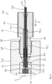
- Die Erfindung wird nachfolgend anhand eines in den Zeichnungen dargestellten Ausführungsbeispiels näher erläutert. In den Zeichnungen zeigen:
- Fig. 1:
- eine erfindungsgemäße Kapillaranschlusseinheit;
- Fig. 2:
- die Kapillaranschlusseinheit aus
Fig. 1 im Längsschnitt; - Fig. 3:
- die Kapillaranschlusseinheit aus
Fig. 1 im Längsschnitt mit relativ zu einander verschobenen Bauteilen; - Fig. 4:
- eine Detailansicht der Kapillaranschlusseinheit gemäß der Markierung IV aus
Fig. 2 ; - Fig. 5:
- eine Detailansicht des Dichtelements und des Sicherungselements der Kapillaranschlusseinheit aus
Fig. 1 ; - Fig. 6:
- die Kapillaranschlusseinheit im mit einem Gegenelement verbundenen Zustand im Längsschnitt;
- Fig. 7:
- eine weitere erfindungsgemäße Kapillaranschlusseinheit im Längsschnitt;
- Fig. 8:
- eine Detailansicht der Kapillaranschlusseinheit gemäß der Markierung VIII aus
Fig. 7 ; - Fig. 9:
- eine Detailansicht des Dichtelements und des Sicherungselements der Kapillaranschlusseinheit aus
Fig. 7 ; - Fig. 10:
- eine Detailansicht des Dichtelements und des Sicherungselements der Kapillaranschlusseinheit aus
Fig. 7 im Längsschnitt; - Fig. 11:
- eine weitere erfindungsgemäße Kapillaranschlusseinheit im Längsschnitt;
- Fig. 12:
- eine Detailansicht der Kapillaranschlusseinheit gemäß der Markierung XII aus
Fig. 11 ; - Fig. 13:
- eine weitere Kapillaranschlusseinheit im Längsschnitt mit relativ zueinander verschobenen Bauteilen;
- Fig. 14:
- die Kapillaranschlusseinheit aus
Fig. 13 im Längsschnitt; - Fig. 15:
- eine weitere erfindungsgemäße Kapillaranschlusseinheit im Längsschnitt;
- Fig. 16:
- eine Detailansicht der Kapillaranschlusseinheit gemäß der Markierung XVI aus
Fig. 15 . - In den
Figuren 1 bis 6 ist eine erste erfindungsgemäße Kapillaranschlusseinheit 10 dargestellt. Die Kapillaranschlusseinheit 10 umfasst ein Anschlusselement 11, das einen Betätigungsabschnitt 11.1 und ein Gewinde 18 aufweist, wobei das Anschlusselement 11 eine axiale Durchführung 12 für eine Kapillare 20 aufweist. Das Anschlusselement 11 ist an einem Endabschnitt 23 einer Kapillare 20 angeordnet und dabei auf der Kapillare 20 verschieblich geführt. Ferner ist das Anschlusselement 11 gegenüber der Kapillare 20 auch frei drehbar, wobei die Kapillare 20 die Rotationsachse bildet. Die Verschiebbarkeit des Anschlusselements 11 auf der Kapillare 20 ist durch ein mit der Kapillare 20 ortsfest verbundenes Stoppelement 26 begrenzt. - Im Bereich eines freien Endes 24 der Kapillare 20 ist umfänglich um die Kapillare 20 herum ein Dichtelement 13 aus einem elastischen Material, insbesondere einem elastischen Kunststoffmaterial, insbesondere einem Thermoplast wie z.B. einem oder mehreren Materialien der Gruppe beinhaltend Fluorkunststoffe, Polyaryletherketone (PAEK), Mischungen aus Fluorkunststoffen und Polyaryletherketonen (PAEK), insbesondere ausgewählt aus der Gruppe beinhaltend Polytetrafluorethylen (PTFE), Polyvinylidenfluorid (PVDF), Polyetherketon (PEK), Polyetheretherketon (PEEK), Polyetherketonketon (PEKK), Polyetheretheretherketon (PEEEK), Polyetherketonetherketonketon (PEKEKK), und Polyetheretherketonetherketon (PEEKEK), bevorzugt Polyetherketon (PEK), Polyetheretherketon (PEEK) und Polyetherketonketon (PEKK), und am meisten bevorzugt Polyetheretherketon (PEEK), angeordnet und stoffschlüssig mit der Kapillare 20 fest verbunden. Die Kapillare 20 ist dabei vorliegend zweischalig ausgebildet und weist eine Innenkapillare oder erste Schale 21 und eine Außenkapillare oder zweite Schale 22 auf, die miteinander verbunden sind (z.B. stoffschlüssig oder kraftschlüssig), wobei die Innenkapillare z.B. aus einem Thermoplasten, aus Glas bzw. fused Silica, Metall, wie z.B. Edelstahl oder Titan, oder Keramik gebildet ist. Die Außenkapillare oder zweite Schale 22 ist z.B. als Edelstahl- oder Titanrohr ausgebildet, das kraft- oder stoffschlüssig mit der Innenkapillare verbunden ist. Alternativ könnte die zweite Schale 22 auch aus einem Thermoplasten gebildet sein.
- Als Thermoplasten für die Kapillarschalen kommen, wie auch beim Dichtelement 13, ein oder mehrere Materialien der Gruppe beinhaltend Fluorkunststoffe, Polyaryletherketone (PAEK), Mischungen aus Fluorkunststoffen und Polyaryletherketonen (PAEK), insbesondere ausgewählt aus der Gruppe beinhaltend Polytetrafluorethylen (PTFE), Polyvinylidenfluorid (PVDF), Polyetherketon (PEK), Polyetheretherketon (PEEK), Polyetherketonketon (PEKK), Polyetheretheretherketon (PEEEK), Polyetherketonetherketonketon (PEKEKK), und Polyetheretherketonetherketon (PEEKEK), bevorzugt Polyetherketon (PEK), Polyetheretherketon (PEEK) und Polyetherketonketon (PEKK) in Frage.
- Als Keramik können Voll- oder Teilkeramiken Verwendung finden. Die Keramik kann aus einem oder mehreren Materialien ausgewählt aus der Gruppe beinhaltend Carbide, Nitride und/oder Oxide (oder anderen) bestehen oder eine Keramik eines oder mehrerer Elemente ausgewählt aus der Gruppe bestehend aus Bor, Aluminium, Silizium, Germanium, Zirkonium, Cer, Seltene Erden (oder anderen) sein. Das Keramikmaterial ist vorzugsweise ausgewählt aus der Gruppe bestehend aus Siliziumcarbid, Siliziumnitrid, Siliziumoxid, Zirkoniumoxid, Zirkoniumcarbid, Titanoxid, Aluminiumoxid, Titancarbid und Komposite und/oder Gemischen davon.
- Unter fused Silica wird dabei Kieselglas (reines Siliziumdioxid) verstanden, das durch Schmelzen von Quarz (kristallinem Siliziumdioxid) bei Temperaturen über 1705 Grad Celsius mit anschließender Abkühlung erhalten wird. Die erkaltete Schmelze ist amorph, also ungeordnet. Durch das Einhalten bestimmter Temperaturen lassen sich Kieselgläser mit hoher Transparenz und sehr wenigen OH-Gruppen erzeugen - letzteres ist von Vorteil, wenn eine Adsorption bestimmter Moleküle auf der Oberfläche unerwünscht ist, z.B. bei GC und HPLC Anwendungen.
- Die hohe chemische Inertheit, die große Temperaturbeständigkeit und die Transparenz sowie dass sich dünnste Kapillaren aus fused Silica herstellen lassen ist dabei äusserst vorteilhaft.
- In der vorliegenden Ausführungsform der Kapillaranschlusseinheit 10 überragt die Innenkapillare 21 zum freien Ende 24 der Kapillare 20 hin die Außenkapillare 22 z.B. um einige zehntel Millimeter bis hin zu mehreren Millimetern. Das Dichtelement 13 ist in diesem Endbereich am freien Ende 24 der Kapillare 20 direkt mit der Innenkapillare 21 stoffschlüssig verbunden. Im rückwärtigen Bereich ist das Dichtelement 13 auch mit der Außenkapillare 22 stoffschlüssig verbunden, z.B. verklebt oder verschweißt. In axialer Richtung einer Längsachse L der Kapillaranschlusseinheit 10 weg vom freien Ende 24 der Kapillare 20 schließt sich an das Dichtelement 13 ein Sicherungselement 16 in Form einer metallischen Hülse, die fest mit der Außenkapillare 22 verbunden ist, an das Dichtelement 13 an. Die feste Verbindung zwischen der z.B. metallischen Außenkapillare 22 und dem Sicherungselement 16 aus Metall erfolgt z.B. durch Verschweißen oder Verlöten oder auch durch Verkleben beider Teile miteinander. An dem Sicherungselement 16 ist wenigstens ein Zahn 17.1 ausgebildet, der zusammen mit Gegenzähnen des Dichtelements eine Verzahnung 17 ausbildet, wobei die Zähne 17.1 am Sicherungselement 16 Hinterschnitte 17.2 ausbilden, um neben einer guten stoffschlüssigen Verbindung mit dem Dichtelement 13 auch eine formschlüssige mechanische Verbindung mit dem Dichtelement 13 herzustellen. Über das Sicherungselement 16 wird eine Drehsicherung des Dichtelements 13 gegenüber der Kapillare 20 hergestellt.
- Die Kapillaranschlusseinheit 10 weist ferner noch ein metallisches Hülsenelement 14 auf, welches das Dichtelement 13 zumindest bereichsweise radial außen umgibt und welches kreiszylindrisch ausgebildet ist. Das metallische Hülsenelement 14 weist ein erstes, dem Anschlusselement 11 zugewandtes Ende 14.1 und ein zweites dem Anschlusselement 11 abgewandtes Ende 14.2 auf. Ausgehend von seinem zweiten Ende 14.2 weist das Hülsenelement 14 einen dem Anschlusselement 11 abgewandten kreiszylindrischen Aufnahmebereich 14.3 für das Dichtelement 13 und das Sicherungselement 16 auf. Ein Innendurchmesser diH des Hülsenelements 14 im Aufnahmebereich 14.3 ist mindestens so groß wie der Außendurchmesser daD des Dichtelements 13, so dass sich das Dichtelement 13 und das Sicherungselement 16, welches den gleichen Außendurchmesser wie das Dichtelement 13 aufweist, gut in den Aufnahmebereich 14.3 des Hülsenelements hineinbewegen lässt. Gleichzeitig ist der Innendurchmesser diH des Hülsenelements 14 im Aufnahmebereich 14.3 aber höchstens 5/100 mm größer als der Außendurchmesser daD des Dichtelements 13, so dass das Dichtelement 13, wenn es gestaucht wird, sich dichtend an das Hülsenelement 14 anlegen kann. Das Hülsenelement 14 ist dabei sowohl gegenüber dem Anschlusselement 11 als auch gegenüber der Kapillare 20 und damit ebenfalls gegenüber dem Dichtelement 13 axial verschieblich geführt. Das Anschlusselement 11 ist relativ zum Hülsenelement 14 verdrehbar. Das Sicherungselement 16 kann vollständig in den Aufnahmebereich 14.3 eingeführt werden, wie aus den
Figuren 1, 2, 3 ,4 und6 ersichtlich. Das Dichtelement 13 kann ebenfalls im Wesentlichen vollständig in den Aufnahmebereich 14.3 eingeschoben werden, wobei im Wesentlichen bedeutet, dass gegebenenfalls einige hundertstel Millimeter des Dichtelements 13 das zweite Ende 14.2 des Hülsenelements 14 noch überragen können. - Vorliegend weist das Anschlusselement 11 noch eine kreiszylindrische Aufnahme in Form eines Sacklochs 19 auf. Das Hülsenelement 14 kann zumindest teilweise in dem Sackloch 19 bzw. der Aufnahme im Anschlusselement 11 aufgenommen werden. Es liegt dann mit seinem dem Anschlusselement 11 zugewandten ersten Ende 14.1 an einer Anschlagfläche 19.1 des Anschlusselements 11 an. Das erste Ende 14.1 des Hülsenelements 14 weist dabei eine erste Schubfläche 15.1 auf, auf die eine Schubkraft F von der Anschlagfläche 19.1 auf das Hülsenelement 14 übertragen werden kann, wenn die Kapillaranschlusseinheit 10, wie in
Fig. 6 dargestellt, in ein Gegenelement 30 eingeschraubt wird zur Herstellung einer Fluidverbindung zwischen dem Gegenelement 30 und der Kapillaranschlusseinheit 10. Zur Herstellung einer solchen Schraubverbindung weist das Gegenelement 30 ein Gegengewinde 38 auf, das mit dem Gewinde 18 des Anschlusselements 11 in Eingriff bringbar ist. - Das Hülsenelement 14 weist ferner noch eine radial innenliegende zweite Schubfläche 15.2 auf, die von dem, dem Anschlusselement 11 abgewandten zweiten Ende 14.2 axial beabstandet ist. Über diese Schubfläche 15.2 kann die Schubkraft F, welche vom Anschlusselement 11 bei Einschrauben in das Gegenelement 30 auf das Hülsenelement 14 ausgeübt wird, an das Dichtelement 13 weitergegeben werden. Diese Weiterleitung erfolgt dabei in der vorliegenden Ausführungsform vermittelt über das Sicherungselement 16, welches mit dem Dichtelement 13 verzahnt ist. Aufgrund der auf das Dichtelement 13 übertragenen Schubkraft F des Anschlusselements 11 wird dieses beim Einschrauben der Kapillaranschlusseinheit 10 in das Gegenelement 30 gegen eine Dichtfläche 34 im Aufnahmeraum 32 des Gegenelements 30 gepresst, wobei gegebenenfalls verdrängtes Material des Dichtelements 30 in den Aufnahmebereich 14.3 im Hülsenelement 14 hineingedrückt wird. Totwasserräume im Anlagebereich der Kapillare 20 mit dem Kapillarkanal 25 an den Kanal 35 des Gegenelements 30 werden dabei zuverlässig vermieden. Ferner kann die Dichtung 13 mit hoher Kraft an die Dichtungsfläche 34 des Gegenelements 30 angedrückt werden, so dass auch mit Hochdruck geführte Fluide von der Kapillaranschlusseinheit 10 sicher an das Gegenelement 30 und den dortigen Kanal 35 überführt werden können.
- Ein Querschnitts-Radius rQS = rs - ri,min der zweiten Schubfläche 15.2 und ein maximaler Querschnitts-Radius rQH = rH - ri,min des Hülsenelements 14 stehen dabei mindestens in einem Verhältnis rQH : rQS von 1,5:1. Dabei ist ri,min der minimale Innenradius des Hülsenelements 14, rs der Außenradius der zweiten Schubfläche 15.2 und rH der Außenradius des Hülsenelements 14 (vergl.
Fig. 4 ). - In den
Figuren 7 bis 10 ist eine weitere Ausführungsform einer erfindungsgemäßen Kapillaranschlusseinheit 10 dargestellt. Diese unterscheidet sich von der zuvor beschriebenen Kapillaranschlusseinheit gemäß denFiguren 1 bis 6 dadurch, dass das Dichtelement 13 nicht nur mit dem Sicherungselement 16 verzahnt ist (siehe Verzahnung 17 in denFiguren 8 bis 10 ), sondern auch dadurch, dass das Dichtelement 13 das Sicherungselement 16 entlang seiner axialen Länge vollständig umschließt, so dass das Dichtelement 13 mit seiner im Aufnahmeraum 14.3 des Hülsenelements 14 liegenden Ende bzw. seiner dort befindlichen Stirnfläche an der zweiten Schubfläche 15.2 des metallischen Hülsenelements 14 anliegt. Ansonsten entspricht die hier dargestellte Ausführungsform der Kapillaranschlusseinheit 10 der vorbeschriebenen Kapillaranschlusseinheit 10 gemäß denFiguren 1 bis 6 , so dass bzgl. hier nicht erwähnter Bezugszeichen und Merkmale vollumfänglich Bezug genommen wird auf die vorgehende Beschreibung zu denFiguren 1 bis 6 . - In den
Figuren 11 und 12 ist eine weitere Ausführungsform einer erfindungsgemäßen Kapillaranschlusseinheit 10 wiedergegeben. Diese unterscheidet sich von der in denFiguren 1 bis 6 dargestellten Ausführungsform einer Kapillaranschlusseinheit 10 dadurch, dass die Innenkapillare bzw. erste Schale 21 der Kapillare 20 als Glaskapillare ausgebildet ist, während die Außenkapillare bzw. zweite Schale 22 der Kapillare 20 aus einem Thermoplasten, z.B. PEEK gebildet ist. Ferner ist bei dieser Ausführungsform einer Kapillaranschlusseinheit 10 nur ein Dichtelement 13 und kein zusätzliches Sicherungselement im Aufnahmeraum 14.3 des metallischen Hülsenelements 14 angeordnet. Dieses Dichtelement 13 aus einem thermoplastischen Material, z.B. PEEK ist mit der Außenkapillare 22 aus dem thermoplastischen Material, wie z.B. PEEK stoffschlüssig verbunden, z.B. mit dieser vollflächig verschweißt. Wie auch bei der Ausführungsform gemäß denFiguren 1 bis 6 und der Ausführungsform gemäß denFiguren 7 bis 10 ist auch hier das Hülsenelement 14 axial verschieblich gegenüber dem Anschlusselement 11 und ist das Dichtelement 13 mit der Kapillare 20 axial verschieblich gegenüber dem Hülsenelement 14. Im Weiteren entspricht die hier dargestellte Ausführungsform der Ausführungsform gemäß denFiguren 1 bis 6 auf deren Beschreibung bzgl. hier nicht erwähnter Bezugszeichen und Merkmale vollumfänglich Bezug genommen wird. - In den
Figuren 13 und 14 ist eine weitere erfindungsgemäße Ausführungsform einer Kapillaranschlusseinheit 10 dargestellt. Diese unterscheidet sich dadurch von der in denFiguren 1 bis 6 dargestellten Kapillaranschlusseinheit, dass hier die Kapillare 20 nicht mehrschalig ausgebildet ist und nur aus einem Material besteht. Vorliegend ist die Kapillare gänzlich aus Edelstahl geformt, sie könnte aber alternativ auch aus einem Thermoplasten, z.B. PEEK oder aus Glas gefertigt sein. Das Dichtelement 13 besteht vorliegend aus einem Thermoplasten, z.B. PEEK und ist mittels der Verzahnung 17 wiederum mit dem Sicherungselement 16 verzahnt, wie dies auch bei der Ausführungsform nach denFiguren 1 bis 6 der Fall ist. Wegen weiterer hier nicht erwähnter Bezugszeichen und Merkmale dieser Ausführungsform der Kapillaranschlusseinheit 10 wird vollumfänglich auf die vorhergehende Beschreibung zur Ausführungsform gemäß denFiguren 1 bis 6 verwiesen. - In den
Figuren 15 und 16 ist eine weitere Ausführungsform einer erfindungsgemäßen Kapillaranschlusseinheit 10 wiedergegeben, die sich dadurch von der in denFiguren 11 und 12 dargestellten Ausführungsform unterscheidet, dass das Hülsenelement 14 nicht in einem Sackloch des Anschlusselements 11 aufgenommen ist, sondern dass das Hülsenelement 14 eine dem Anschlusselement 11 zugewandte radialumfängliche flanschartige Verbreiterung 14.4 aufweist, wodurch eine großflächige erste Schubfläche 15.1 am Hülsenelement 14 erzeugt ist. Diese kann großflächig an der Anschlagfläche 19.1 des Anschlusselements 11 in Anlage gebracht werden, wobei die Anschlagfläche 19.1 in dieser Ausführungsform der Kapillaranschlusseinheit 10 durch eine Stirnfläche des Anschlusselements 11 gebildet wird. Die Kapillare 20 ist in dieser Ausführungsform zweischalig ausgebildet und weist wiederum eine Innenkapillare aus Glas, einem Thermoplasten, z.B. PEEK oder Metall, z.B. Edelstahl oder Titan, auf. Die Außenkapillare 22 ist aus einem Thermoplasten, z.B. aus PEEK gefertigt, wobei das Dichtelement 13, welches ebenfalls aus einem Thermoplasten, z.B. PEEK besteht, stoffschlüssig mit der Außenkapillare 22 verbunden ist, z.B. mit dieser verschweißt ist. Die Kapillare 20 mit dem daran angeordneten Dichtelement 13 ist wiederum gegenüber dem Hülsenelement 14 (begrenzt) verschieblich und das Hülsenelement 14 begrenzt (verschieblich) gegenüber dem Anschlusselement 11. Es bleibt anzumerken, dass anstelle einer mehrschaligen Kapillare auch in dieser Ausführungsform eine einschalige Kapillare, z.B. aus einem Thermoplasten, wie z.B. PEEK, Glas, Metall, z.B. Edelstahl oder Titan, oder einer der vorbeschriebenen Keramiken verwendet werden kann. - Wegen weiterer hier nicht explizit erwähnter Bezugszeichen und Merkmale wird verwiesen auf die vorhergehende Beschreibung zu den
Figuren 1 bis 6 und11 bis 12 . -
- 10
- Kapillaranschlusseinheit
- 11
- Anschlusselement
- 11.1
- Betätigungsabschnitte
- 12
- axiale Durchführung
- 13
- Dichtelement
- 14
- metallisches Hülsenelement
- 14.1
- erstes Ende
- 14.2
- zweites Ende
- 14.3
- Aufnahmebereich (für das Dichtelement)
- 14.4
- flanschartige Verbreiterung
- 15.1
- erste Schubfläche
- 15.2
- zweite Schubfläche
- 16
- Sicherungselement
- 17
- Verzahnung
- 17.1
- Zähne
- 17.2
- Hinterschnitte
- 18
- Gewinde
- 19
- Sackloch
- 19.1
- Anschlagfläche
- 20
- Kapillare
- 21
- erste Schale (Innenkapillare)
- 22
- zweite Schale (Außenkapillare)
- 23
- Endabschnitt
- 24
- freies Ende
- 25
- Kapillarkanal
- 26
- Stoppelement
- 30
- Gegenelement
- 32
- Aufnahmeraum
- 34
- Dichtfläche
- 35
- Kanal
- 38
- Gegengewinde
- F
- Schubkraft
- L
- Längsachse (der Kapillaranschlusseinheit)
Claims (10)
- Kapillaranschlusseinheit (10) für Analysegeräte und medizinische Geräte,- mit einer Kapillare (20), die wenigstens einen Endabschnitt (23) und daran ein freies Ende (24) aufweist,- mit wenigstens einem an dem Endabschnitt (23) der Kapillare (20) angeordneten Anschlusselement (11),
wobei das Anschlusselement (11) eine axiale Durchführung (12) aufweist, durch welche die Kapillare (20) verläuft,- mit einem Dichtelement (13), welches die Kapillare (20) wenigstens im Bereich ihres freien Endes (24) umgibt und- mit einem metallischen Hülsenelement (14), welches zumindest bereichsweise das Dichtelement (13) radial außen umgibt, und welches ein erstes, dem Anschlusselement (11) zugewandtes Ende (14.1) und einen dem Anschlusselement (11) abgewandten Aufnahmebereich (14.3) aufweist,wobei das Anschlusselement (11) mit dem freien Ende (24) der Kapillare (20) dazu eingerichtet ist, lösbar mit einem Gegenelement (30) verbunden zu werden und eine axiale Schubkraft (F) auf das Dichtelement (13) auszuüben,dadurch gekennzeichnet, dass das Hülsenelement (14) sowohl gegenüber dem Anschlusselement (11) als auch gegenüber der Kapillare (20) mit dem Dichtelement (13) axial verschieblich geführt ist,dass ein Innendurchmesser diH des Hülsenelements (14) in dem, dem Anschlusselement (11) abgewandten Aufnahmebereich (14.3) mindestens so groß ist wie der Außendurchmesser daD des Dichtelements (13), wobei das Hülsenelement (14) dazu konfiguriert ist, das Dichtelement (13) im Wesentlichen vollständig in seinen Aufnahmebereich (14.3) aufzunehmen unddass das Hülsenelement (14) an seinem dem Anschlusselement (11) zugewandten ersten Ende (14.1) eine, in axialer Richtung dem Anschlusselement (11) zugewandte erste Schubfläche (15.1) zur Aufnahme der Schubkraft (F) des Anschlusselements (11) und nur eine radial innenliegende, zu einem dem Anschlusselement (11) abgewandten zweiten Ende (14.2) axial beabstandete und dem Dichtelement (13) zugewandte zweite Schubfläche (15.2) zur Weiterleitung der Schubkraft (F) an das Dichtelement (13) aufweistund dadurch,dass radial außen an der Kapillare (20) in einem Bereich direkt angrenzend an das Dichtelement (13) zum Anschlusselement (11) hin ein stationäres Sicherungselement (16) angeordnet ist, das mit der Kapillare (20) stoffschlüssig verbunden ist und mit dem Dichtelement (13) über eine Verzahnung (17) stoff- und formschlüssig verbunden ist. - Kapillaranschlusseinheit (1) nach Anspruch 1, dadurch gekennzeichnet, dass die Kapillaranschlusseinheit (1) keinen röhrenförmigen Kapillareinsatz mit ringförmigem Abschluss am Ende der Kapillare (20) aufweist.
- Kapillaranschlusseinheit (1) nach Anspruch 1 oder 2, dadurch gekennzeichnet, dass das Dichtelement (13) mit der Kapillare (20) stoffschlüssig und fest verbunden ist.
- Kapillaranschlusseinheit (1) nach einem der Ansprüche 1 bis 3, dadurch gekennzeichnet, dass das Dichtelement (13) aus wenigstens einem Material der Gruppe beinhaltend Fluorkunststoffe, Polyaryletherketone (PAEK), Mischungen aus Fluorkunststoffen und Polyaryletherketonen (PAEK), insbesondere ausgewählt aus der Gruppe beinhaltend Polytetrafluorethylen (PTFE), Polyvinylidenfluorid (PVDF), Polyetherketon (PEK), Polyetheretherketon (PEEK), Polyetherketonketon (PEKK), Polyetheretheretherketon (PEEEK), Polyetherketonetherketonketon (PEKEKK), und Polyetheretherketonetherketon (PEEKEK) gebildet ist.
- Kapillaranschlusseinheit (1) nach einem der Ansprüche 1 bis 4, dadurch gekennzeichnet, dass die zweite Schubfläche (15.2) als Kreisringfläche ausgebildet ist, wobei ein Querschnitts-Radius rQS = rs - ri,min der zweiten Schubfläche (15.2) und ein maximaler Querschnitts-Radius rQH = rH - ri,min des Hülsenelements (14) mindestens im Verhältnis rQH : rQS von 1,5:1 stehen und wobei ri,min der minimale Innenradius des Hülsenelements (14) ist, rs der Außenradius der zweiten Schubfläche (15.2) ist und rH der Außenradius des Hülsenelements (14) ist.
- Kapillaranschlusseinheit (1) nach einem der Ansprüche 1 bis 5, dadurch gekennzeichnet, dass die Kapillare (20) zumindest im Endabschnitt (23) der Kapillare (20), mehrschalig, vorzugsweise zweischalig ausgebildet ist.
- Kapillaranschlusseinheit (1) nach Anspruch 6, dadurch gekennzeichnet, dass eine erste, innere Schale (21) der Kapillare (20) aus einem Material der Gruppe bestehend aus Glas, insbesondere fused Silica, einem thermoplastischen Material, Metall und Keramik gebildet ist
und
dass eine zweite, äußere Schale (22) aus einem Material der Gruppe einem thermoplastischen Material, Metall und Keramik gebildet ist. - Kapillaranschlusseinheit (1) nach einem der Ansprüche 1 bis 7, dadurch gekennzeichnet, dass das stationäre Sicherungselement (16) aus Metall, insbesondere aus Stahl gefertigt und ring- oder hülsenförmig ausgebildet ist und die Kapillare (20) bereichsweise umfängt.
- Kapillaranschlusseinheit (1) nach einem der Ansprüche 1 bis 8, dadurch gekennzeichnet, dass die radial innenliegende zweite Schubfläche (15.2) des Hülsenelements (14) vermittelt über das stationäre Hülsenelement (14) mit dem Dichtelement (13) zur Übertragung der Schubkraft (F) des Anschlusselements (11) zusammenwirkt.
- Kapillaranschlusseinheit (1) nach einem der Ansprüche 1 bis 9, dadurch gekennzeichnet, dass das Anschlusselement (11) auf der Kapillare (20) begrenzt verschiebbar geführt ist, wobei die Verschiebbarkeit des Anschlusselements (11) auf der Kapillare (20) durch ein mit der Kapillare (20) ortsfest verbundenes Stoppelement (26) begrenzt ist.
Applications Claiming Priority (2)
| Application Number | Priority Date | Filing Date | Title |
|---|---|---|---|
| EP16001083.1A EP3244205A1 (de) | 2016-05-12 | 2016-05-12 | Kapillaranschlusseinheit für analysegeräte und medizinische geräte |
| PCT/EP2017/000584 WO2017194193A1 (de) | 2016-05-12 | 2017-05-12 | Kapillaranschlusseinheit für analysegeräte und medizinische geräte |
Publications (3)
| Publication Number | Publication Date |
|---|---|
| EP3455620A1 EP3455620A1 (de) | 2019-03-20 |
| EP3455620B1 true EP3455620B1 (de) | 2024-11-13 |
| EP3455620C0 EP3455620C0 (de) | 2024-11-13 |
Family
ID=56068590
Family Applications (2)
| Application Number | Title | Priority Date | Filing Date |
|---|---|---|---|
| EP16001083.1A Withdrawn EP3244205A1 (de) | 2016-05-12 | 2016-05-12 | Kapillaranschlusseinheit für analysegeräte und medizinische geräte |
| EP17722684.2A Active EP3455620B1 (de) | 2016-05-12 | 2017-05-12 | Kapillaranschlusseinheit für analysegeräte und medizinische geräte |
Family Applications Before (1)
| Application Number | Title | Priority Date | Filing Date |
|---|---|---|---|
| EP16001083.1A Withdrawn EP3244205A1 (de) | 2016-05-12 | 2016-05-12 | Kapillaranschlusseinheit für analysegeräte und medizinische geräte |
Country Status (3)
| Country | Link |
|---|---|
| US (1) | US11135593B2 (de) |
| EP (2) | EP3244205A1 (de) |
| WO (1) | WO2017194193A1 (de) |
Families Citing this family (6)
| Publication number | Priority date | Publication date | Assignee | Title |
|---|---|---|---|---|
| DE102017129674A1 (de) * | 2017-12-12 | 2019-06-13 | Dionex Softron Gmbh | Steckereinheiten, insbesondere für HPLC, Verbindungssystem und entsprechende Verwendung |
| EP3942294B1 (de) | 2019-03-19 | 2026-01-07 | Waters Technologies Corporation | Abnehmbare dichtungsvorrichtung für fluidische kupplung, fluidische kupplung und verfahren zur fluidischen kupplung |
| DE102019002641A1 (de) * | 2019-04-10 | 2020-10-15 | Möller Medical Gmbh & Co Kg | Vorrichtung zum Anschließen eines Rohres oder Schlauches, bevorzugt einer Kapillare |
| US11782032B2 (en) | 2019-08-14 | 2023-10-10 | Waters Technologies Corporation | Fitting for fluidic coupling in a chromatography system |
| JP7524737B2 (ja) * | 2020-11-27 | 2024-07-30 | 株式会社島津製作所 | クロマトグラフィ検出器用フローセルアセンブリの構造およびキャピラリの製造方法 |
| WO2026093455A1 (en) * | 2024-10-30 | 2026-05-07 | The Chancellor, Masters And Scholars Of The University Of Cambridge | Modular coaxially aligned fluidic device |
Citations (1)
| Publication number | Priority date | Publication date | Assignee | Title |
|---|---|---|---|---|
| DE102012110991A1 (de) * | 2012-11-15 | 2014-05-15 | Dionex Softron Gmbh | Steckereinheit und Verbindungssystem zum Verbinden von Kapillaren, insbesondere für die Hochleistungsflüssigkeitschromatographie |
Family Cites Families (8)
| Publication number | Priority date | Publication date | Assignee | Title |
|---|---|---|---|---|
| US5669637A (en) * | 1996-05-29 | 1997-09-23 | Optimize Technologies, Inc. | Miniature fitting assembly for micro-tubing |
| DE102009022368C5 (de) | 2009-05-22 | 2020-12-17 | Dionex Softron Gmbh | Steckereinheit und Verbindungssystem für das Verbinden von Kapillaren, insbesondere für die Hochleistungsflüssigkeitschromatographie |
| GB2482175B (en) * | 2010-07-23 | 2016-01-13 | Agilent Technologies Inc | Fitting element with bio-compatible sealing |
| DE102011050037B3 (de) * | 2011-05-02 | 2012-06-14 | Dionex Softron Gmbh | Steckereinheit und Verbindungssystem zum Verbinden von Kapillaren, insbesondere für die Hochleistungsflüssigkeitschromatographie |
| CH705381B1 (de) * | 2011-08-15 | 2025-02-28 | Moeller Medical Gmbh | Rohr beinhaltend Metallmantel mit Kunststoff-Inlay zur Verwendung als Chromatographiesäule, insbesondere als HPLC-Säule |
| DE102011082470A1 (de) * | 2011-09-09 | 2013-03-14 | Agilent Technologies Inc. | Fitting mit lokaler Kapillarweitenanpassung |
| US9347056B2 (en) * | 2012-10-26 | 2016-05-24 | Seiko Epson Corporation | Nucleic acid extraction device, and nucleic acid extraction method, nucleic acid extraction kit, and nucleic acid extraction apparatus, each using the same |
| US10655761B2 (en) * | 2014-10-23 | 2020-05-19 | Idex Health & Science Llc | Face-sealing fluidic connection system |
-
2016
- 2016-05-12 EP EP16001083.1A patent/EP3244205A1/de not_active Withdrawn
-
2017
- 2017-05-12 US US16/300,369 patent/US11135593B2/en active Active
- 2017-05-12 WO PCT/EP2017/000584 patent/WO2017194193A1/de not_active Ceased
- 2017-05-12 EP EP17722684.2A patent/EP3455620B1/de active Active
Patent Citations (1)
| Publication number | Priority date | Publication date | Assignee | Title |
|---|---|---|---|---|
| DE102012110991A1 (de) * | 2012-11-15 | 2014-05-15 | Dionex Softron Gmbh | Steckereinheit und Verbindungssystem zum Verbinden von Kapillaren, insbesondere für die Hochleistungsflüssigkeitschromatographie |
Also Published As
| Publication number | Publication date |
|---|---|
| WO2017194193A1 (de) | 2017-11-16 |
| US11135593B2 (en) | 2021-10-05 |
| EP3455620C0 (de) | 2024-11-13 |
| EP3455620A1 (de) | 2019-03-20 |
| US20190091693A1 (en) | 2019-03-28 |
| EP3244205A1 (de) | 2017-11-15 |
Similar Documents
| Publication | Publication Date | Title |
|---|---|---|
| WO2017194193A1 (de) | Kapillaranschlusseinheit für analysegeräte und medizinische geräte | |
| DE102012110991B4 (de) | Steckereinheit und Verbindungssystem zum Verbinden von Kapillaren, insbesondere für die Hochleistungsflüssigkeitschromatographie | |
| DE69809322T2 (de) | Gewindeverbinder für Rohre | |
| EP1355100B1 (de) | Steckkupplung für fluidische Systeme | |
| DE19982677B4 (de) | Vierteldrehungs-Schnellverbindungs-Rohrverbindungsstückanordnung | |
| DE102008059897B4 (de) | Steckereinheit und Verbindungssystem für das Verbinden von Kapillaren, insbesondere für die Hochleistungsflüssigkeitschromatographie | |
| EP2088357B1 (de) | Unlösbare Verbindung aus einem Fitting, einer Hülse und einem Rohr sowie Fitting für Fluidleitungen und Hülse für Fluidleitungsrohre | |
| EP2205299B1 (de) | Spritze mit wechselbarer nadel | |
| EP2703707B1 (de) | System zum Herstellen einer dichten Rohrverbindung | |
| EP2433119A1 (de) | Steckereinheit und verbindungssystem für das verbinden von kapillaren, insbesondere für die hochleistungsflüssigkeitschromatographie | |
| WO2012149930A1 (de) | Steckereinheit und verbindungssystem zum verbinden von kapillaren, insbesondere für die hochleistungsflüssigkeitschromatographie | |
| EP2818152B1 (de) | Luer-Lock-Verbinder mit Nuten | |
| DE112015001853T5 (de) | Hochdruck-Fluid-Verbindungsanordnungen | |
| EP0781386A1 (de) | Anschlussstück für die rohrleitungskupplung eines hochdruckreinigungsgeräts | |
| EP3139074B1 (de) | Frostsichere aussenarmatur und verfahren zur montage derselben | |
| EP1636521B1 (de) | Verbindungseinrichtung für ein rohr oder dgl | |
| EP3184917B1 (de) | Strömungsmengenregler, koppelteil und heizung-brauchwasser-anlage | |
| DE10207201A1 (de) | Pressfitting | |
| EP2450556B1 (de) | Anschlussanordnung für eine rohrförmige Kraftstoffleitung | |
| DE20116201U1 (de) | Wiederverwendbarer Rohrverschluss | |
| EP4078002B1 (de) | Schnellkupplung zum verbinden | |
| EP1947337A2 (de) | Pumpe für das Befüllen von Fahrradreifen | |
| DE10236059A1 (de) | Kupplung | |
| WO2010028872A1 (de) | Nicht lösbare rohrleitungsverbindung | |
| EP2369212B1 (de) | Verbindungsanordnung |
Legal Events
| Date | Code | Title | Description |
|---|---|---|---|
| STAA | Information on the status of an ep patent application or granted ep patent |
Free format text: STATUS: UNKNOWN |
|
| STAA | Information on the status of an ep patent application or granted ep patent |
Free format text: STATUS: THE INTERNATIONAL PUBLICATION HAS BEEN MADE |
|
| PUAI | Public reference made under article 153(3) epc to a published international application that has entered the european phase |
Free format text: ORIGINAL CODE: 0009012 |
|
| STAA | Information on the status of an ep patent application or granted ep patent |
Free format text: STATUS: REQUEST FOR EXAMINATION WAS MADE |
|
| 17P | Request for examination filed |
Effective date: 20181128 |
|
| AK | Designated contracting states |
Kind code of ref document: A1 Designated state(s): AL AT BE BG CH CY CZ DE DK EE ES FI FR GB GR HR HU IE IS IT LI LT LU LV MC MK MT NL NO PL PT RO RS SE SI SK SM TR |
|
| AX | Request for extension of the european patent |
Extension state: BA ME |
|
| DAV | Request for validation of the european patent (deleted) | ||
| DAX | Request for extension of the european patent (deleted) | ||
| STAA | Information on the status of an ep patent application or granted ep patent |
Free format text: STATUS: EXAMINATION IS IN PROGRESS |
|
| 17Q | First examination report despatched |
Effective date: 20220329 |
|
| GRAP | Despatch of communication of intention to grant a patent |
Free format text: ORIGINAL CODE: EPIDOSNIGR1 |
|
| STAA | Information on the status of an ep patent application or granted ep patent |
Free format text: STATUS: GRANT OF PATENT IS INTENDED |
|
| RIC1 | Information provided on ipc code assigned before grant |
Ipc: B01L 3/00 20060101ALI20231207BHEP Ipc: G01N 30/60 20060101AFI20231207BHEP |
|
| INTG | Intention to grant announced |
Effective date: 20240105 |
|
| GRAJ | Information related to disapproval of communication of intention to grant by the applicant or resumption of examination proceedings by the epo deleted |
Free format text: ORIGINAL CODE: EPIDOSDIGR1 |
|
| STAA | Information on the status of an ep patent application or granted ep patent |
Free format text: STATUS: EXAMINATION IS IN PROGRESS |
|
| INTC | Intention to grant announced (deleted) | ||
| GRAP | Despatch of communication of intention to grant a patent |
Free format text: ORIGINAL CODE: EPIDOSNIGR1 |
|
| STAA | Information on the status of an ep patent application or granted ep patent |
Free format text: STATUS: GRANT OF PATENT IS INTENDED |
|
| INTG | Intention to grant announced |
Effective date: 20240607 |
|
| GRAS | Grant fee paid |
Free format text: ORIGINAL CODE: EPIDOSNIGR3 |
|
| GRAA | (expected) grant |
Free format text: ORIGINAL CODE: 0009210 |
|
| STAA | Information on the status of an ep patent application or granted ep patent |
Free format text: STATUS: THE PATENT HAS BEEN GRANTED |
|
| AK | Designated contracting states |
Kind code of ref document: B1 Designated state(s): AL AT BE BG CH CY CZ DE DK EE ES FI FR GB GR HR HU IE IS IT LI LT LU LV MC MK MT NL NO PL PT RO RS SE SI SK SM TR |
|
| REG | Reference to a national code |
Ref country code: GB Ref legal event code: FG4D Free format text: NOT ENGLISH |
|
| REG | Reference to a national code |
Ref country code: CH Ref legal event code: EP |
|
| REG | Reference to a national code |
Ref country code: DE Ref legal event code: R096 Ref document number: 502017016562 Country of ref document: DE |
|
| REG | Reference to a national code |
Ref country code: IE Ref legal event code: FG4D Free format text: LANGUAGE OF EP DOCUMENT: GERMAN |
|
| U01 | Request for unitary effect filed |
Effective date: 20241213 |
|
| U07 | Unitary effect registered |
Designated state(s): AT BE BG DE DK EE FI FR IT LT LU LV MT NL PT RO SE SI Effective date: 20241223 |
|
| PG25 | Lapsed in a contracting state [announced via postgrant information from national office to epo] |
Ref country code: HR Free format text: LAPSE BECAUSE OF FAILURE TO SUBMIT A TRANSLATION OF THE DESCRIPTION OR TO PAY THE FEE WITHIN THE PRESCRIBED TIME-LIMIT Effective date: 20241113 Ref country code: IS Free format text: LAPSE BECAUSE OF FAILURE TO SUBMIT A TRANSLATION OF THE DESCRIPTION OR TO PAY THE FEE WITHIN THE PRESCRIBED TIME-LIMIT Effective date: 20250313 |
|
| PG25 | Lapsed in a contracting state [announced via postgrant information from national office to epo] |
Ref country code: ES Free format text: LAPSE BECAUSE OF FAILURE TO SUBMIT A TRANSLATION OF THE DESCRIPTION OR TO PAY THE FEE WITHIN THE PRESCRIBED TIME-LIMIT Effective date: 20241113 |
|
| PG25 | Lapsed in a contracting state [announced via postgrant information from national office to epo] |
Ref country code: NO Free format text: LAPSE BECAUSE OF FAILURE TO SUBMIT A TRANSLATION OF THE DESCRIPTION OR TO PAY THE FEE WITHIN THE PRESCRIBED TIME-LIMIT Effective date: 20250213 |
|
| PG25 | Lapsed in a contracting state [announced via postgrant information from national office to epo] |
Ref country code: GR Free format text: LAPSE BECAUSE OF FAILURE TO SUBMIT A TRANSLATION OF THE DESCRIPTION OR TO PAY THE FEE WITHIN THE PRESCRIBED TIME-LIMIT Effective date: 20250214 |
|
| PG25 | Lapsed in a contracting state [announced via postgrant information from national office to epo] |
Ref country code: PL Free format text: LAPSE BECAUSE OF FAILURE TO SUBMIT A TRANSLATION OF THE DESCRIPTION OR TO PAY THE FEE WITHIN THE PRESCRIBED TIME-LIMIT Effective date: 20241113 |
|
| PG25 | Lapsed in a contracting state [announced via postgrant information from national office to epo] |
Ref country code: RS Free format text: LAPSE BECAUSE OF FAILURE TO SUBMIT A TRANSLATION OF THE DESCRIPTION OR TO PAY THE FEE WITHIN THE PRESCRIBED TIME-LIMIT Effective date: 20250213 |
|
| U20 | Renewal fee for the european patent with unitary effect paid |
Year of fee payment: 9 Effective date: 20250406 |
|
| PG25 | Lapsed in a contracting state [announced via postgrant information from national office to epo] |
Ref country code: SM Free format text: LAPSE BECAUSE OF FAILURE TO SUBMIT A TRANSLATION OF THE DESCRIPTION OR TO PAY THE FEE WITHIN THE PRESCRIBED TIME-LIMIT Effective date: 20241113 |
|
| PG25 | Lapsed in a contracting state [announced via postgrant information from national office to epo] |
Ref country code: SK Free format text: LAPSE BECAUSE OF FAILURE TO SUBMIT A TRANSLATION OF THE DESCRIPTION OR TO PAY THE FEE WITHIN THE PRESCRIBED TIME-LIMIT Effective date: 20241113 |
|
| PG25 | Lapsed in a contracting state [announced via postgrant information from national office to epo] |
Ref country code: CZ Free format text: LAPSE BECAUSE OF FAILURE TO SUBMIT A TRANSLATION OF THE DESCRIPTION OR TO PAY THE FEE WITHIN THE PRESCRIBED TIME-LIMIT Effective date: 20241113 |
|
| PLBE | No opposition filed within time limit |
Free format text: ORIGINAL CODE: 0009261 |
|
| STAA | Information on the status of an ep patent application or granted ep patent |
Free format text: STATUS: NO OPPOSITION FILED WITHIN TIME LIMIT |
|
| 26N | No opposition filed |
Effective date: 20250814 |
|
| REG | Reference to a national code |
Ref country code: CH Ref legal event code: H13 Free format text: ST27 STATUS EVENT CODE: U-0-0-H10-H13 (AS PROVIDED BY THE NATIONAL OFFICE) Effective date: 20251223 |
|
| PG25 | Lapsed in a contracting state [announced via postgrant information from national office to epo] |
Ref country code: CH Free format text: LAPSE BECAUSE OF NON-PAYMENT OF DUE FEES Effective date: 20250531 |
|
| GBPC | Gb: european patent ceased through non-payment of renewal fee |
Effective date: 20250512 |
|
| PG25 | Lapsed in a contracting state [announced via postgrant information from national office to epo] |
Ref country code: MC Free format text: LAPSE BECAUSE OF FAILURE TO SUBMIT A TRANSLATION OF THE DESCRIPTION OR TO PAY THE FEE WITHIN THE PRESCRIBED TIME-LIMIT Effective date: 20241113 |
|
| PG25 | Lapsed in a contracting state [announced via postgrant information from national office to epo] |
Ref country code: GB Free format text: LAPSE BECAUSE OF NON-PAYMENT OF DUE FEES Effective date: 20250512 |
|
| PG25 | Lapsed in a contracting state [announced via postgrant information from national office to epo] |
Ref country code: IE Free format text: LAPSE BECAUSE OF NON-PAYMENT OF DUE FEES Effective date: 20250512 |