EP3454785B1 - Heart valve with stent having varying cell densities - Google Patents
Heart valve with stent having varying cell densities Download PDFInfo
- Publication number
- EP3454785B1 EP3454785B1 EP17725023.0A EP17725023A EP3454785B1 EP 3454785 B1 EP3454785 B1 EP 3454785B1 EP 17725023 A EP17725023 A EP 17725023A EP 3454785 B1 EP3454785 B1 EP 3454785B1
- Authority
- EP
- European Patent Office
- Prior art keywords
- cells
- section
- stent
- row
- aortic
- Prior art date
- Legal status (The legal status is an assumption and is not a legal conclusion. Google has not performed a legal analysis and makes no representation as to the accuracy of the status listed.)
- Active
Links
- 210000003709 heart valve Anatomy 0.000 title claims description 62
- 230000007704 transition Effects 0.000 claims description 42
- 238000000034 method Methods 0.000 description 9
- OYPRJOBELJOOCE-UHFFFAOYSA-N Calcium Chemical compound [Ca] OYPRJOBELJOOCE-UHFFFAOYSA-N 0.000 description 7
- 210000001765 aortic valve Anatomy 0.000 description 7
- 229910052791 calcium Inorganic materials 0.000 description 7
- 239000011575 calcium Substances 0.000 description 7
- 239000008280 blood Substances 0.000 description 6
- 210000004369 blood Anatomy 0.000 description 6
- 230000017531 blood circulation Effects 0.000 description 5
- 210000004115 mitral valve Anatomy 0.000 description 4
- 210000004351 coronary vessel Anatomy 0.000 description 3
- 230000000694 effects Effects 0.000 description 3
- -1 for example Polymers 0.000 description 3
- 230000002452 interceptive effect Effects 0.000 description 3
- 229910001000 nickel titanium Inorganic materials 0.000 description 3
- 229920000642 polymer Polymers 0.000 description 3
- 210000000709 aorta Anatomy 0.000 description 2
- 230000008901 benefit Effects 0.000 description 2
- 239000000560 biocompatible material Substances 0.000 description 2
- 230000002308 calcification Effects 0.000 description 2
- 230000000747 cardiac effect Effects 0.000 description 2
- 238000002513 implantation Methods 0.000 description 2
- 210000005240 left ventricle Anatomy 0.000 description 2
- 229910052751 metal Inorganic materials 0.000 description 2
- 239000002184 metal Substances 0.000 description 2
- 150000002739 metals Chemical class 0.000 description 2
- HLXZNVUGXRDIFK-UHFFFAOYSA-N nickel titanium Chemical compound [Ti].[Ti].[Ti].[Ti].[Ti].[Ti].[Ti].[Ti].[Ti].[Ti].[Ti].[Ni].[Ni].[Ni].[Ni].[Ni].[Ni].[Ni].[Ni].[Ni].[Ni].[Ni].[Ni].[Ni].[Ni] HLXZNVUGXRDIFK-UHFFFAOYSA-N 0.000 description 2
- 229920000139 polyethylene terephthalate Polymers 0.000 description 2
- 239000005020 polyethylene terephthalate Substances 0.000 description 2
- 229920001343 polytetrafluoroethylene Polymers 0.000 description 2
- 239000004810 polytetrafluoroethylene Substances 0.000 description 2
- 238000007789 sealing Methods 0.000 description 2
- 229910001285 shape-memory alloy Inorganic materials 0.000 description 2
- 238000001356 surgical procedure Methods 0.000 description 2
- 210000001519 tissue Anatomy 0.000 description 2
- 206010067171 Regurgitation Diseases 0.000 description 1
- 229920010741 Ultra High Molecular Weight Polyethylene (UHMWPE) Polymers 0.000 description 1
- 210000001015 abdomen Anatomy 0.000 description 1
- 230000009471 action Effects 0.000 description 1
- 210000003484 anatomy Anatomy 0.000 description 1
- 238000004873 anchoring Methods 0.000 description 1
- 238000013459 approach Methods 0.000 description 1
- 239000012620 biological material Substances 0.000 description 1
- 230000004087 circulation Effects 0.000 description 1
- 229910003460 diamond Inorganic materials 0.000 description 1
- 239000010432 diamond Substances 0.000 description 1
- 230000006870 function Effects 0.000 description 1
- 239000007943 implant Substances 0.000 description 1
- 230000003993 interaction Effects 0.000 description 1
- 238000012986 modification Methods 0.000 description 1
- 230000004048 modification Effects 0.000 description 1
- 210000004165 myocardium Anatomy 0.000 description 1
- 230000009467 reduction Effects 0.000 description 1
- 238000007634 remodeling Methods 0.000 description 1
- 210000000591 tricuspid valve Anatomy 0.000 description 1
Images


Classifications
-
- A—HUMAN NECESSITIES
- A61—MEDICAL OR VETERINARY SCIENCE; HYGIENE
- A61F—FILTERS IMPLANTABLE INTO BLOOD VESSELS; PROSTHESES; DEVICES PROVIDING PATENCY TO, OR PREVENTING COLLAPSING OF, TUBULAR STRUCTURES OF THE BODY, e.g. STENTS; ORTHOPAEDIC, NURSING OR CONTRACEPTIVE DEVICES; FOMENTATION; TREATMENT OR PROTECTION OF EYES OR EARS; BANDAGES, DRESSINGS OR ABSORBENT PADS; FIRST-AID KITS
- A61F2/00—Filters implantable into blood vessels; Prostheses, i.e. artificial substitutes or replacements for parts of the body; Appliances for connecting them with the body; Devices providing patency to, or preventing collapsing of, tubular structures of the body, e.g. stents
- A61F2/02—Prostheses implantable into the body
- A61F2/24—Heart valves ; Vascular valves, e.g. venous valves; Heart implants, e.g. passive devices for improving the function of the native valve or the heart muscle; Transmyocardial revascularisation [TMR] devices; Valves implantable in the body
- A61F2/2412—Heart valves ; Vascular valves, e.g. venous valves; Heart implants, e.g. passive devices for improving the function of the native valve or the heart muscle; Transmyocardial revascularisation [TMR] devices; Valves implantable in the body with soft flexible valve members, e.g. tissue valves shaped like natural valves
- A61F2/2418—Scaffolds therefor, e.g. support stents
-
- A—HUMAN NECESSITIES
- A61—MEDICAL OR VETERINARY SCIENCE; HYGIENE
- A61F—FILTERS IMPLANTABLE INTO BLOOD VESSELS; PROSTHESES; DEVICES PROVIDING PATENCY TO, OR PREVENTING COLLAPSING OF, TUBULAR STRUCTURES OF THE BODY, e.g. STENTS; ORTHOPAEDIC, NURSING OR CONTRACEPTIVE DEVICES; FOMENTATION; TREATMENT OR PROTECTION OF EYES OR EARS; BANDAGES, DRESSINGS OR ABSORBENT PADS; FIRST-AID KITS
- A61F2230/00—Geometry of prostheses classified in groups A61F2/00 - A61F2/26 or A61F2/82 or A61F9/00 or A61F11/00 or subgroups thereof
- A61F2230/0002—Two-dimensional shapes, e.g. cross-sections
- A61F2230/0028—Shapes in the form of latin or greek characters
- A61F2230/0054—V-shaped
-
- A—HUMAN NECESSITIES
- A61—MEDICAL OR VETERINARY SCIENCE; HYGIENE
- A61F—FILTERS IMPLANTABLE INTO BLOOD VESSELS; PROSTHESES; DEVICES PROVIDING PATENCY TO, OR PREVENTING COLLAPSING OF, TUBULAR STRUCTURES OF THE BODY, e.g. STENTS; ORTHOPAEDIC, NURSING OR CONTRACEPTIVE DEVICES; FOMENTATION; TREATMENT OR PROTECTION OF EYES OR EARS; BANDAGES, DRESSINGS OR ABSORBENT PADS; FIRST-AID KITS
- A61F2230/00—Geometry of prostheses classified in groups A61F2/00 - A61F2/26 or A61F2/82 or A61F9/00 or A61F11/00 or subgroups thereof
- A61F2230/0063—Three-dimensional shapes
- A61F2230/0073—Quadric-shaped
- A61F2230/008—Quadric-shaped paraboloidal
-
- A—HUMAN NECESSITIES
- A61—MEDICAL OR VETERINARY SCIENCE; HYGIENE
- A61F—FILTERS IMPLANTABLE INTO BLOOD VESSELS; PROSTHESES; DEVICES PROVIDING PATENCY TO, OR PREVENTING COLLAPSING OF, TUBULAR STRUCTURES OF THE BODY, e.g. STENTS; ORTHOPAEDIC, NURSING OR CONTRACEPTIVE DEVICES; FOMENTATION; TREATMENT OR PROTECTION OF EYES OR EARS; BANDAGES, DRESSINGS OR ABSORBENT PADS; FIRST-AID KITS
- A61F2250/00—Special features of prostheses classified in groups A61F2/00 - A61F2/26 or A61F2/82 or A61F9/00 or A61F11/00 or subgroups thereof
- A61F2250/0014—Special features of prostheses classified in groups A61F2/00 - A61F2/26 or A61F2/82 or A61F9/00 or A61F11/00 or subgroups thereof having different values of a given property or geometrical feature, e.g. mechanical property or material property, at different locations within the same prosthesis
- A61F2250/0015—Special features of prostheses classified in groups A61F2/00 - A61F2/26 or A61F2/82 or A61F9/00 or A61F11/00 or subgroups thereof having different values of a given property or geometrical feature, e.g. mechanical property or material property, at different locations within the same prosthesis differing in density or specific weight
-
- A—HUMAN NECESSITIES
- A61—MEDICAL OR VETERINARY SCIENCE; HYGIENE
- A61F—FILTERS IMPLANTABLE INTO BLOOD VESSELS; PROSTHESES; DEVICES PROVIDING PATENCY TO, OR PREVENTING COLLAPSING OF, TUBULAR STRUCTURES OF THE BODY, e.g. STENTS; ORTHOPAEDIC, NURSING OR CONTRACEPTIVE DEVICES; FOMENTATION; TREATMENT OR PROTECTION OF EYES OR EARS; BANDAGES, DRESSINGS OR ABSORBENT PADS; FIRST-AID KITS
- A61F2250/00—Special features of prostheses classified in groups A61F2/00 - A61F2/26 or A61F2/82 or A61F9/00 or A61F11/00 or subgroups thereof
- A61F2250/0014—Special features of prostheses classified in groups A61F2/00 - A61F2/26 or A61F2/82 or A61F9/00 or A61F11/00 or subgroups thereof having different values of a given property or geometrical feature, e.g. mechanical property or material property, at different locations within the same prosthesis
- A61F2250/0036—Special features of prostheses classified in groups A61F2/00 - A61F2/26 or A61F2/82 or A61F9/00 or A61F11/00 or subgroups thereof having different values of a given property or geometrical feature, e.g. mechanical property or material property, at different locations within the same prosthesis differing in thickness
Definitions
- the present disclosure relates in general to heart valve replacement and, in particular, to collapsible prosthetic heart valves. More particularly, the present disclosure relates to stents for heart valves having variable cell density and to methods for creating same.
- Prosthetic heart valves that are collapsible to a relatively small circumferential size can be delivered into a patient less invasively than valves that are not collapsible.
- a collapsible valve may be delivered into a patient via a tube-like delivery apparatus such as a catheter, a trocar, a laparoscopic instrument, or the like. This collapsibility can avoid the need for a more invasive procedure such as full open-chest, open-heart surgery.
- Collapsible prosthetic heart valves typically take the form of a valve structure mounted on a stent.
- a stent There are two common types of stents on which the valve structures are mounted: a self-expanding stent or a balloon-expandable stent.
- a self-expanding stent or a balloon-expandable stent.
- the valve To place such valves into a delivery apparatus and ultimately into a patient, the valve must first be collapsed or crimped to reduce its circumferential size.
- the prosthetic valve When a collapsed prosthetic valve has reached the desired implant site in the patient (e.g., at or near the annulus of the patient's heart valve that is to be replaced by the prosthetic valve), the prosthetic valve can be deployed or released from the delivery apparatus and re-expanded to full operating size.
- this generally involves releasing the entire valve, and then expanding a balloon positioned within the valve stent.
- the stent automatically expands as the sheath covering the valve is withdrawn.
- WO 2009/094188 discloses a stent for prosthetic heart valves.
- US 2011/238168 discloses stents for prosthetic heart valves.
- US 2015/272737 discloses transcatheter mitral valve stent frames.
- US 2011/264196 discloses stents for prosthetic heart valves.
- CN 101 961 273 discloses a valvular prosthetic replacement device with buffer action and stent.
- a prosthetic heart valve for replacing a native valve includes a collapsible and expandable stent extending between a proximal end and a distal end, the stent including an annulus section adjacent the proximal end, the annulus section having cells arranged in at least one annulus row, each said annulus row having a same first number of cells, the first number defining a first cell density, an aortic section adjacent the distal end, the aortic section having cells arranged in at least one aortic row, each said aortic row having a same second number of cells, the second number defining a second cell density, the first cell density being greater than the second cell density, and a transition section disposed between the annulus section and the aortic section, the transition section having cells arranged in at least one transition row, the number of cells per transition row defining a third cell density that is different from the first cell density and the second cell density; and a valve assembly disposed within the stent, wherein each
- proximal and distal when used in connection with a prosthetic heart valve, refer to the inflow and outflow ends, respectively, of the heart valve corresponding to natural circulation of blood through a healthy heart.
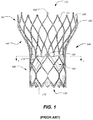
- FIG. 1 shows one such stent-supported prosthetic heart valve 100 including an expandable stent 102 and a valve assembly 104 as is known in the art.
- Prosthetic heart valve 100 is designed to replace a native tricuspid valve of a patient, such as a native aortic valve. It should be noted that while the embodiments discussed herein relate predominantly to prosthetic aortic valves having a stent with a shape as illustrated in FIG.
- the general principles disclosed may be equally applied to a bicuspid valve, such as the mitral valve, and the stent could have different shapes, such as a flared or conical annulus section, a less-bulbous aortic section, and the like, and a differently shaped transition section.
- Stent 102 may be formed from biocompatible materials that are capable of self-expansion, such as, for example, shape memory alloys, such as the nickel-titanium alloy known as "Nitinol" or other suitable metals or polymers. Stent 102 extends from proximal or annulus end 130 to distal or aortic end 132, and includes annulus section 140 adjacent proximal end 130, transition section 141 and aortic section 142 adjacent distal end 132. Annulus section 140 may have a relatively small cross-section in the expanded configuration, while aortic section 142 may have a relatively large cross-section in the expanded configuration. Preferably, annulus section 140 is in the form of a cylinder having a substantially constant diameter along its length.
- Transition section 141 may taper outwardly from annulus section 140 to aortic section 142.
- Each of the sections of stent 102 includes a plurality of struts 160 forming diamond-shaped cells 162 connected to one another in one or more annular rows around the stent.
- annulus section 140 may have two annular rows of complete cells 162 and aortic section 142 and transition section 141 may each have one or more annular rows of partial cells 162.
- Cells 162 in aortic section 142 may be larger than cells 162 in annulus section 140. The larger cells in aortic section 142 better enable prosthetic valve 100 to be positioned in the native valve annulus without the stent structure interfering with blood flow to the coronary arteries.
- Stent 102 may include one or more retaining elements 168 at distal end 132 thereof, retaining elements 168 being sized and shaped to cooperate with female retaining structures (not shown) provided on a deployment device.
- the engagement of retaining elements 168 with the female retaining structures on the deployment device helps maintain prosthetic heart valve 100 in assembled relationship with the deployment device, minimizes longitudinal movement of the prosthetic heart valve relative to the deployment device during unsheathing or resheathing procedures, and helps prevent rotation of the prosthetic heart valve relative to the deployment device as the deployment device is advanced to the target location and the heart valve deployed.
- Prosthetic heart valve 100 includes valve assembly 104 preferably secured to stent 102 in annulus section 140.
- Valve assembly 104 includes cuff 176 and a plurality of leaflets 178 which collectively function as a one-way valve by coapting with one another.
- As a prosthetic aortic valve valve 100 has three leaflets 178.
- other prosthetic heart valves with which the stent of the present disclosure may be used may have a greater or lesser number of leaflets.
- cuff 176 is shown in FIG. 1 as being disposed on the luminal or inner surface of annulus section 140, it is contemplated that, with the stent configurations disclosed herein, the cuff may be disposed on the abluminal or outer surface of the annulus section or may cover all or part of either or both of the luminal and abluminal surfaces. Cuff may also have a loose fit and incorporate longitudinal and/or circumferential pleats, folds or other elements to aid in paravalvular leakage.
- Both cuff 176 and leaflets 178 may be wholly or partly formed of any suitable biological material or polymer such as, for example, polyethylene terephthalate (PET), ultra-high-molecular-weight polyethylene (UHMWPE), or polytetrafluoroethylene (PTFE).
- PET polyethylene terephthalate
- UHMWPE ultra-high-molecular-weight polyethylene
- PTFE polytetrafluoroethylene
- Leaflets 178 may be attached along their lower belly portions to cells 162 of stent 102, with the commissure between adjacent leaflets 178 attached to commissure features 166.
- each commissure feature 166 may lie at the intersection of four cells 162, two of the cells being adjacent one another in the same annular row, and the other two cells being in different annular rows and lying in end-to-end relationship. In other stent configurations, however, this need not be the case, and the commissure feature need not lie at the intersection of four cells.
- commissure features 166 are positioned entirely within annulus section 140 or at the juncture of annulus section 140 and transition section 141.
- Commissure features 166 may include one or more eyelets which facilitate the suturing of the leaflet commissure to stent 102 and can be of any geometric shape that is driven by the number and orientation of holes needed for suturing.
- Prosthetic heart valve 100 may be used to replace a native aortic valve, another transcatheter valve, a surgical heart valve or a heart valve that has undergone a surgical procedure.
- Prosthetic heart valve 100 may be delivered to the desired site (e.g ., near the native aortic annulus) using any suitable delivery device.
- prosthetic heart valve 100 is disposed inside the delivery device in the collapsed configuration.
- the delivery device may be introduced into a patient using a transfemoral, transaortic, transsubclavian, transapical, transseptal or any other percutaneous approach. Once the delivery device has reached the target site, the user may deploy prosthetic heart valve 100.
- prosthetic heart valve 100 Upon deployment, prosthetic heart valve 100 expands so that annulus section 140 is in secure engagement within the native aortic annulus and native calcified leaflets. When prosthetic heart valve 100 is properly positioned inside the patient's aortic annulus, it works as a one-way valve, allowing blood to flow from the left ventricle of the heart to the aorta, and preventing blood from flowing in the opposite direction into the ventricle.
- FIG. 2 is a highly schematic cross-sectional illustration of prosthetic heart valve 100 disposed within native valve annulus 250.
- valve assembly 104 has a substantially circular cross-section which is disposed within the non-circular native valve annulus 250.
- prosthetic heart valve 100 is shown with a circular cross-section for the sake of clarity, certain portions will deflect to accommodate the geometry in the anatomy.
- heart valve 100 may have an elliptical or D-shaped cross-section for use in mitral, tricuspid, or diseased bicuspid valve applications.
- gaps 200 form between heart valve 100 and native valve annulus 250.
- Blood flowing through these gaps and past valve assembly 104 of prosthetic heart valve 100 can cause regurgitation and other inefficiencies which reduce cardiac performance.
- Such improper fitment may be due to suboptimal native valve annulus geometry due, for example, to calcification of native valve annulus 250 or to irregularities in unresected native leaflets.
- two calcium nodules 190 are disposed near the circumference of the heart valve, the calcium nodules limiting the proper expansion of heart valve 100.
- stent 102 is typically crimped during delivery and allowed to expand within the native vale annulus. This expansion of the stent 102 includes an expansion of each individual cell 162.
- calcium nodules prevent the expansion of one or more of the cells 162 of the stent resulting in a warped or under-expanded region 192 of stent 102. This non-circular or unintended configuration may, in turn, affect the functioning of valve assembly 104, which is disposed within stent 102.
- an increased number of cells or struts may lead to other forms of leakage due to microchannels formed between the rigid struts and the native valve annulus, for example, the calcium nodules present on the native leaflets and/or annulus.
- a high cell density also may reduce blood flow to the coronary arteries or other blood flow, or the accessibility of guidewires and other devices.
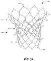
- Fig. 3A shows one example of a self-expanding stent 300 to address this problem.
- Stent 300 may be formed from biocompatible materials that are capable of self-expansion, such as, for example, shape memory alloys, such as the Nitinol or other suitable metals or polymers.
- Stent 300 extends from proximal or annulus end 302 to distal or aortic end 304, and includes annulus section 310 adjacent proximal end 302, transition section 312 and aortic section 314 adjacent distal end 304.
- Annulus section 310 may have a relatively small cross-section in the expanded configuration, while aortic section 314 may have a relatively large cross-section in the expanded configuration.
- annulus section 310 is in the form of a cylinder having a substantially constant diameter along its length but can utilize other shapes and configurations.
- Transition section 312 may taper outwardly from annulus section 310 to aortic section 314.
- Each of the sections of stent 300 includes a plurality of struts 320 forming cells 330,332,334 connected to one another in one or more annular rows around the stent.
- annulus section 310 may have three annular rows of complete first cells 330 and aortic section 314 and transition section 312 may each have one or more annular rows of second and third full cells 332,334 or partial cells.
- Third cells 334 in aortic section 314 may be larger than first cells 330 in annulus section 310.
- the larger third cells 334 in aortic section 314 better enable stent 300 to be positioned in the native valve annulus without the stent structure interfering with blood flow to the coronary arteries.
- Stent 300 may include one or more retaining elements 340 at distal end 304 thereof, retaining elements 340 being sized and shaped to cooperate with female retaining structures (not shown) provided on a deployment device.
- the engagement of retaining elements 340 with the female retaining structures on the deployment device helps maintain stent 300 in assembled relationship with the deployment device, minimizes longitudinal movement of the stent relative to the deployment device during unsheathing or resheathing procedures, and helps prevent rotation of the stent relative to the deployment device as the deployment device is advanced to the target location and the heart valve deployed.
- a number of commissure features 350 are also provided for attaching a valve assembly to the stent as described above.
- each row of cells in annulus section 310 has a greater number of smaller first cells 330 than the number of larger third cells 334 in each row of cells in aortic section 314.
- the cell density of rows comprising first cells 330 is greater than the cell density of rows comprising third cells 334, referred to herein as the second cell density.
- the first cell density is equal to twelve cells per row and the second cell density is equal to nine cells per row.
- Transition section 312 including second cells 332 may be disposed in several rows having one or more cell densities that are different from the first cell density and the second cell density.
- first cells 330 and third cells 334 may be generally diamond-shaped cells
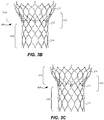
- second cells 332a,332b,332c of transition section 312 may have other shapes as best seen in the side views of Figs. 3D-E .
- Relatively large oversized second cells 332a are disposed on each side of commissure features 350 so that between each pair of commissure features 350 are two oversized second cells 332a.
- Each oversized second cell 332a has an asymmetric shape formed by five struts 361a-e and commissure feature 350.
- Struts 361a,361b may be shared struts that also form part of third cells 334 in aortic section 314.
- struts 361c,361d may be shared struts that also form part of first cells 330 in annulus section 310.
- strut 361e may be a shared strut with an adjacent second cell 332b, strut 361e being different from the remaining struts by connecting to struts 361a and 361d at positions spaced from their respective ends.
- strut 361e of the transition section does not, as it compensates for the asymmetry of the cell as well as the presence of commissure feature 350 on the opposite side. It will be understood that this asymmetry is only one possible configuration, and that other configurations not having this asymmetry are possible and that all or some of the struts may be connected to apices.
- each two oversized second cells 332a are two lower second cells 332b and one symmetric upper second cell 332c.
- Lower second cells 332b also have an asymmetric shape defined by four struts that are shared with other cells as well as a protuberance of a third cell 334.
- strut 371a is shared with a neighboring upper second cell 332c
- struts 371b,371c are shared with first cells 330 in annulus section 310
- strut 361e is shared with oversized second cell 332a as previously discussed.
- a curved protuberance 372 of a third cell 334 in aortic section 314 also forms a portion of lower cell 332b.
- symmetric upper second cell 332c it is generally diamond shaped and defined by four struts, two struts 380 that are shared with neighboring third cells 334 in aortic section 314 and two struts 371a, each of which is shared with one of the two lower asymmetric second cells 332b.
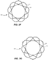
- the foregoing arrangement of cells provides a stent 300 having an annulus section with twelve cells in each row; a transition section 312 having one row with six full cells and six substantially half cells and another row with three full cells and six substantially half cells; and an aortic section 314 with nine full cells.
- This arrangement of cells provides a transition of the cell density from twelve in the annulus section 310 to nine in the aortic section 314.
- struts 371a forming the lower V-shape of symmetric upper second cell 332c may have a thickness that is less than the thickness of all the other struts of stent 300. This reduced thickness of struts 371a may allow for even collapsing and expanding of the stent despite the asymmetry of some of the cells and the odd number of cells in certain sections of the stent.
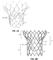
- Figs. 4A-B illustrate one variant of the stent in which the transition section has been modified. Elements similar to those of Figs. 3A-G are shown as having like numbers preceded by a "4".
- stent 400 is similar to stent 300 in every way except for transition section 412, which includes two oversized asymmetric second cells 432a that are similar to oversized second cells 332a, and enlarged generally diamond-shaped cells 432b, defined by struts 481a-d and protuberance 482 (there are two of each strut and each protruberance in each cell as cells 432b are symmetrical).
- each half of enlarged cell 432b includes strut 481a that is shared with a neighboring third cell 434 in aortic section 414, strut 481b that is shared with an adjacent oversized asymmetric second cell 432a, strut 481c that is shared with one of first cells 430a in annulus section 410, and strut 481d that is shared with another first cell 430b in annulus section 410, struts 481c and 481d being substantially aligned with one another linearly.
- Protuberance 482 of a third cell 434 also forms part of enlarged cell 432b.
- enlarged cell 432b is described as being a part of transition section 412, as shown in Figs. 4A-B , it may be considered to be part of annulus section 410 as well.
- the foregoing arrangement of cells provides a stent 400 having an annulus section 410 with two rows of cells each having twelve cells, and a third row of cells having nine full cells and three partial cells; a transition section 412 having six full cells and three partial cells; and an aortic section 414 having nine full cells.
- This arrangement of cells provides a transition of cell density from a cell density of twelve in the annulus section 410 to a cell density of nine in the aortic section 414 that is different from the transition provided by stent 300.
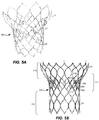
- stent 500 is similar to stent 300 in every way except for transition section 512, and specifically the splitting of oversized second cells 332a into four cells as shown.
- two additional struts 580a,580b generally form an X-shape, splitting the area previously occupied by oversized second cells 332a in the embodiment of Figs. 3A-G into four cells 590a-d.
- the arrangement of cells described above provides a stent 500 having an annular section 510 with three rows of cells each having twelve cells; a transition section 512 having a row of cells having twelve cells, a second row of cells having twelve full cells and three partial cells, and a third row of cells having six full cells and three partial cells; and an aortic section 514 having nine full cells.
- This arrangement of cells provides a transition of cell density from a cell density of twelve in the annular section 510 to a cell density of nine in the aortic section 514 that is different from the transition provided by both stents 300 and 400.
- transition section may be modified in a number of ways to bridge between the annulus sections 310,410,510 and the aortic sections 314,414,514, which have different cell densities, retaining the benefits of a larger density near the annulus section and the relatively smaller density near the aortic section.
- the stent could have different shapes, such as a flared or conical annulus section, a less-bulbous aortic section, and the like, as well as a differently shaped transition section. Additionally, though the stents have been described in connection with expandable transcatheter aortic valve replacement, they may also be used in connection with other expandable cardiac valves, as well as with other devices in which it is desirable to create a seal between the periphery of the device and the adjacent body tissue, while at the same time not interfering with other body structures.
- each of annulus section, transition section and aortic section may include any number of rows of cells as desired.
- a stent may be formed that transitions from a low cell density to a high cell density and then back to a low cell density, or vice versa.
- multiple transition sections may be added to transition between two, three, four, five, six, seven or even eight cell densities, some or all of the cell densities being different than others.
- a stent may have rows of nine cells adjacent the proximal end, then transition to rows of twelve cells, and then back to rows of nine cells at the distal end. Another stent may transition from rows of twelve cells to rows of nine cells and back to rows of twelve cells. Additionally, a stent may be formed that has a different cell density for each row of cells, or section of cells.
Description
- The present disclosure relates in general to heart valve replacement and, in particular, to collapsible prosthetic heart valves. More particularly, the present disclosure relates to stents for heart valves having variable cell density and to methods for creating same.
- Prosthetic heart valves that are collapsible to a relatively small circumferential size can be delivered into a patient less invasively than valves that are not collapsible. For example, a collapsible valve may be delivered into a patient via a tube-like delivery apparatus such as a catheter, a trocar, a laparoscopic instrument, or the like. This collapsibility can avoid the need for a more invasive procedure such as full open-chest, open-heart surgery.
- Collapsible prosthetic heart valves typically take the form of a valve structure mounted on a stent. There are two common types of stents on which the valve structures are mounted: a self-expanding stent or a balloon-expandable stent. To place such valves into a delivery apparatus and ultimately into a patient, the valve must first be collapsed or crimped to reduce its circumferential size.
- When a collapsed prosthetic valve has reached the desired implant site in the patient (e.g., at or near the annulus of the patient's heart valve that is to be replaced by the prosthetic valve), the prosthetic valve can be deployed or released from the delivery apparatus and re-expanded to full operating size. For balloon-expandable valves, this generally involves releasing the entire valve, and then expanding a balloon positioned within the valve stent. For self-expanding valves, on the other hand, the stent automatically expands as the sheath covering the valve is withdrawn.
-
WO 2009/094188 discloses a stent for prosthetic heart valves.US 2011/238168 discloses stents for prosthetic heart valves.US 2015/272737 discloses transcatheter mitral valve stent frames.US 2011/264196 discloses stents for prosthetic heart valves.CN 101 961 273 discloses a valvular prosthetic replacement device with buffer action and stent. - According to the invention, a prosthetic heart valve for replacing a native valve includes a collapsible and expandable stent extending between a proximal end and a distal end, the stent including an annulus section adjacent the proximal end, the annulus section having cells arranged in at least one annulus row, each said annulus row having a same first number of cells, the first number defining a first cell density, an aortic section adjacent the distal end, the aortic section having cells arranged in at least one aortic row, each said aortic row having a same second number of cells, the second number defining a second cell density, the first cell density being greater than the second cell density, and a transition section disposed between the annulus section and the aortic section, the transition section having cells arranged in at least one transition row, the number of cells per transition row defining a third cell density that is different from the first cell density and the second cell density; and a valve assembly disposed within the stent, wherein each cell in the at least one aortic row is directly coupled to a circumferentially adjacent cell in the at least one aortic row.
- Various embodiments in accordance with the present disclosure will now be described with reference to the appended drawings. It is to be appreciated that these drawings depict only some embodiments and are therefore not to be considered limiting of its scope.
-
FIG. 1 is a side elevational view of a conventional prosthetic heart valve; -
FIG. 2 is a highly schematic cross-sectional view taken along line A-A ofFIG. 1 and showing the prosthetic heart valve disposed within a native valve annulus; -
FIG. 3A is a perspective view of one example of a stent for a prosthetic heart valve having a varying cell density; -
FIGS. 3B-G are front, back, left, right, bottom and top views of the stent ofFIG. 3A ; -
FIGS. 4A-B are perspective and front views of another example of a stent for a prosthetic heart valve having a varying cell density; and -
FIGS. 5A-B are perspective and front views of yet another example of a stent for a prosthetic heart valve having a varying cell density. - Inaccurate deployment and anchoring of a prosthetic heart valve in a patient may result in the leakage of blood between the implanted heart valve and the native valve annulus, commonly referred to as paravalvular leakage (also known as "perivalvular leakage"). In aortic valves, this leakage enables blood to flow from the aorta back into the left ventricle, reducing cardiac efficiency and putting a greater strain on the heart muscle. Additionally, calcification of the aortic valve and/or anatomical variations from one patient to another may affect the performance of the prosthetic valve and the interaction between the implanted valve and the calcified tissue is believed to be relevant to leakage, as will be outlined below. There is a need for further improvements to the devices, systems, and methods for positioning and sealing collapsible prosthetic heart valves during implantation in a patient. Specifically, there is a need for further improvements to the devices, systems, and methods for accurately implanting a prosthetic heart valve. Among other advantages, the present disclosure may address one or more of these needs.
- As used herein, the terms "proximal" and "distal," when used in connection with a prosthetic heart valve, refer to the inflow and outflow ends, respectively, of the heart valve corresponding to natural circulation of blood through a healthy heart.
- The stent of the present disclosure may be used in connection with prosthetic heart valves.
FIG. 1 shows one such stent-supportedprosthetic heart valve 100 including anexpandable stent 102 and avalve assembly 104 as is known in the art.Prosthetic heart valve 100 is designed to replace a native tricuspid valve of a patient, such as a native aortic valve. It should be noted that while the embodiments discussed herein relate predominantly to prosthetic aortic valves having a stent with a shape as illustrated inFIG. 1 , the general principles disclosed may be equally applied to a bicuspid valve, such as the mitral valve, and the stent could have different shapes, such as a flared or conical annulus section, a less-bulbous aortic section, and the like, and a differently shaped transition section. - Stent 102 may be formed from biocompatible materials that are capable of self-expansion, such as, for example, shape memory alloys, such as the nickel-titanium alloy known as "Nitinol" or other suitable metals or polymers.
Stent 102 extends from proximal orannulus end 130 to distal oraortic end 132, and includesannulus section 140 adjacentproximal end 130,transition section 141 andaortic section 142 adjacentdistal end 132.Annulus section 140 may have a relatively small cross-section in the expanded configuration, whileaortic section 142 may have a relatively large cross-section in the expanded configuration. Preferably,annulus section 140 is in the form of a cylinder having a substantially constant diameter along its length.Transition section 141 may taper outwardly fromannulus section 140 toaortic section 142. Each of the sections ofstent 102 includes a plurality ofstruts 160 forming diamond-shaped cells 162 connected to one another in one or more annular rows around the stent. For example, as shown inFIG. 1 ,annulus section 140 may have two annular rows ofcomplete cells 162 andaortic section 142 andtransition section 141 may each have one or more annular rows ofpartial cells 162.Cells 162 inaortic section 142 may be larger thancells 162 inannulus section 140. The larger cells inaortic section 142 better enableprosthetic valve 100 to be positioned in the native valve annulus without the stent structure interfering with blood flow to the coronary arteries. -
Stent 102 may include one or moreretaining elements 168 atdistal end 132 thereof, retainingelements 168 being sized and shaped to cooperate with female retaining structures (not shown) provided on a deployment device. The engagement of retainingelements 168 with the female retaining structures on the deployment device helps maintainprosthetic heart valve 100 in assembled relationship with the deployment device, minimizes longitudinal movement of the prosthetic heart valve relative to the deployment device during unsheathing or resheathing procedures, and helps prevent rotation of the prosthetic heart valve relative to the deployment device as the deployment device is advanced to the target location and the heart valve deployed. -
Prosthetic heart valve 100 includesvalve assembly 104 preferably secured tostent 102 inannulus section 140.Valve assembly 104 includescuff 176 and a plurality ofleaflets 178 which collectively function as a one-way valve by coapting with one another. As a prosthetic aortic valve,valve 100 has threeleaflets 178. However, it will be appreciated that other prosthetic heart valves with which the stent of the present disclosure may be used may have a greater or lesser number of leaflets. - Although
cuff 176 is shown inFIG. 1 as being disposed on the luminal or inner surface ofannulus section 140, it is contemplated that, with the stent configurations disclosed herein, the cuff may be disposed on the abluminal or outer surface of the annulus section or may cover all or part of either or both of the luminal and abluminal surfaces. Cuff may also have a loose fit and incorporate longitudinal and/or circumferential pleats, folds or other elements to aid in paravalvular leakage. Bothcuff 176 andleaflets 178 may be wholly or partly formed of any suitable biological material or polymer such as, for example, polyethylene terephthalate (PET), ultra-high-molecular-weight polyethylene (UHMWPE), or polytetrafluoroethylene (PTFE). -
Leaflets 178 may be attached along their lower belly portions tocells 162 ofstent 102, with the commissure betweenadjacent leaflets 178 attached tocommissure features 166. As can be seen inFIG. 1 , eachcommissure feature 166 may lie at the intersection of fourcells 162, two of the cells being adjacent one another in the same annular row, and the other two cells being in different annular rows and lying in end-to-end relationship. In other stent configurations, however, this need not be the case, and the commissure feature need not lie at the intersection of four cells. Preferably, commissure features 166 are positioned entirely withinannulus section 140 or at the juncture ofannulus section 140 andtransition section 141. Commissure features 166 may include one or more eyelets which facilitate the suturing of the leaflet commissure tostent 102 and can be of any geometric shape that is driven by the number and orientation of holes needed for suturing. -
Prosthetic heart valve 100 may be used to replace a native aortic valve, another transcatheter valve, a surgical heart valve or a heart valve that has undergone a surgical procedure.Prosthetic heart valve 100 may be delivered to the desired site (e.g., near the native aortic annulus) using any suitable delivery device. During delivery,prosthetic heart valve 100 is disposed inside the delivery device in the collapsed configuration. The delivery device may be introduced into a patient using a transfemoral, transaortic, transsubclavian, transapical, transseptal or any other percutaneous approach. Once the delivery device has reached the target site, the user may deployprosthetic heart valve 100. Upon deployment,prosthetic heart valve 100 expands so thatannulus section 140 is in secure engagement within the native aortic annulus and native calcified leaflets. Whenprosthetic heart valve 100 is properly positioned inside the patient's aortic annulus, it works as a one-way valve, allowing blood to flow from the left ventricle of the heart to the aorta, and preventing blood from flowing in the opposite direction into the ventricle. -
FIG. 2 is a highly schematic cross-sectional illustration ofprosthetic heart valve 100 disposed withinnative valve annulus 250. As seen in the figure,valve assembly 104 has a substantially circular cross-section which is disposed within the non-circularnative valve annulus 250. It will be understood that whileprosthetic heart valve 100 is shown with a circular cross-section for the sake of clarity, certain portions will deflect to accommodate the geometry in the anatomy. Alternatively,heart valve 100 may have an elliptical or D-shaped cross-section for use in mitral, tricuspid, or diseased bicuspid valve applications. At certain locations around the perimeter ofheart valve 100,gaps 200 form betweenheart valve 100 andnative valve annulus 250. Blood flowing through these gaps andpast valve assembly 104 ofprosthetic heart valve 100 can cause regurgitation and other inefficiencies which reduce cardiac performance. Such improper fitment may be due to suboptimal native valve annulus geometry due, for example, to calcification ofnative valve annulus 250 or to irregularities in unresected native leaflets. - Additionally, in this illustration, two
calcium nodules 190 are disposed near the circumference of the heart valve, the calcium nodules limiting the proper expansion ofheart valve 100. As previously discussed,stent 102 is typically crimped during delivery and allowed to expand within the native vale annulus. This expansion of thestent 102 includes an expansion of eachindividual cell 162. In some cases, calcium nodules prevent the expansion of one or more of thecells 162 of the stent resulting in a warped or under-expandedregion 192 ofstent 102. This non-circular or unintended configuration may, in turn, affect the functioning ofvalve assembly 104, which is disposed withinstent 102. - It has been learned that the presence of calcium nodules affects the ability of
stent 102 to properly expand. Additionally, it has been learned that the density of cells-that is, the number of cells per row of cells formed by stent 102 - will also affect the expansion of the stent. A greater cell density may result in a stent that expands with greater radial force and that is more rigid once expanded, reducing the risk of under-expansion of the stent. Additionally, if one or more calcium nodules prevent the full expansion of one of the cells of the stent, a greater cell density in a row will reduce the effects of the under-expanded cell on the overall geometry of the stent and the valve assembly disposed therein. Thus, it has been discovered that, in general, a higher cell density is better in dealing with the effects of under-expansion of cells due to calcium nodules. - On the other hand, it has also been discovered that an increased number of cells or struts may lead to other forms of leakage due to microchannels formed between the rigid struts and the native valve annulus, for example, the calcium nodules present on the native leaflets and/or annulus. A high cell density also may reduce blood flow to the coronary arteries or other blood flow, or the accessibility of guidewires and other devices.
- Prior art stent configurations do not recognize this problem. For example, some transcatheter prosthetic heart valves have balloon-expandable stents and are forcibly expanded within the native valve annulus. While such a technique may address underexpansion, by way of remodeling the patient annulus, it involves a slightly more complicated procedure and requires the use of a balloon that is correctly positioned to expand the prosthetic heart valve instead of the self-expanding prosthetic heart valves described herein. This could also increase the risk of annulus rupture if all patient anatomical factors are not carefully considered. Alternatively, some self-expanding stent designs simply have an increased number of cells to increase stent rigidity, but show no recognition of the problems associated with microchanneling and a reduction in sealing performance along with the coronary access challenges.
-
Fig. 3A shows one example of a self-expandingstent 300 to address this problem.Stent 300 may be formed from biocompatible materials that are capable of self-expansion, such as, for example, shape memory alloys, such as the Nitinol or other suitable metals or polymers.Stent 300 extends from proximal orannulus end 302 to distal oraortic end 304, and includesannulus section 310 adjacentproximal end 302,transition section 312 andaortic section 314 adjacentdistal end 304.Annulus section 310 may have a relatively small cross-section in the expanded configuration, whileaortic section 314 may have a relatively large cross-section in the expanded configuration. Preferably,annulus section 310 is in the form of a cylinder having a substantially constant diameter along its length but can utilize other shapes and configurations.Transition section 312 may taper outwardly fromannulus section 310 toaortic section 314. Each of the sections ofstent 300 includes a plurality ofstruts 320 forming cells 330,332,334 connected to one another in one or more annular rows around the stent. For example, as shown inFIG. 3A ,annulus section 310 may have three annular rows of completefirst cells 330 andaortic section 314 andtransition section 312 may each have one or more annular rows of second and third full cells 332,334 or partial cells.Third cells 334 inaortic section 314 may be larger thanfirst cells 330 inannulus section 310. The largerthird cells 334 inaortic section 314 better enablestent 300 to be positioned in the native valve annulus without the stent structure interfering with blood flow to the coronary arteries. -
Stent 300 may include one ormore retaining elements 340 atdistal end 304 thereof, retainingelements 340 being sized and shaped to cooperate with female retaining structures (not shown) provided on a deployment device. The engagement of retainingelements 340 with the female retaining structures on the deployment device helps maintainstent 300 in assembled relationship with the deployment device, minimizes longitudinal movement of the stent relative to the deployment device during unsheathing or resheathing procedures, and helps prevent rotation of the stent relative to the deployment device as the deployment device is advanced to the target location and the heart valve deployed. A number of commissure features 350 are also provided for attaching a valve assembly to the stent as described above. - As best seen in the front and back views of
Figs. 3B-C , each row of cells inannulus section 310 has a greater number of smallerfirst cells 330 than the number of largerthird cells 334 in each row of cells inaortic section 314. In other words, the cell density of rows comprisingfirst cells 330, referred to herein as the first cell density, is greater than the cell density of rows comprisingthird cells 334, referred to herein as the second cell density. In the example shown, the first cell density is equal to twelve cells per row and the second cell density is equal to nine cells per row. The relatively higher first cell density provides a greater radial force and reduces the effect of an underexpanded cell on the performance of a valve, while the relatively lower second cell density minimizes interference with blood flow, such as coronary access flow, and provides better access by guidewires or other tools during or after an implantation procedure.Transition section 312 includingsecond cells 332 may be disposed in several rows having one or more cell densities that are different from the first cell density and the second cell density. - While
first cells 330 andthird cells 334 may be generally diamond-shaped cells,second cells 332a,332b,332c oftransition section 312 may have other shapes as best seen in the side views ofFigs. 3D-E . Relatively large oversizedsecond cells 332a are disposed on each side of commissure features 350 so that between each pair of commissure features 350 are two oversizedsecond cells 332a. Each oversizedsecond cell 332a has an asymmetric shape formed by fivestruts 361a-e andcommissure feature 350.Struts third cells 334 inaortic section 314. Likewise, struts 361c,361d may be shared struts that also form part offirst cells 330 inannulus section 310. Finally, strut 361e may be a shared strut with an adjacent second cell 332b, strut 361e being different from the remaining struts by connecting tostruts stent 300 connect to one another at the apices of other cells, strut 361e of the transition section does not, as it compensates for the asymmetry of the cell as well as the presence ofcommissure feature 350 on the opposite side. It will be understood that this asymmetry is only one possible configuration, and that other configurations not having this asymmetry are possible and that all or some of the struts may be connected to apices. - Turning to
Fig. 3E , between each two oversizedsecond cells 332a are two lower second cells 332b and one symmetric upper second cell 332c. Lower second cells 332b also have an asymmetric shape defined by four struts that are shared with other cells as well as a protuberance of athird cell 334. Specifically,strut 371a is shared with a neighboring upper second cell 332c, struts 371b,371c are shared withfirst cells 330 inannulus section 310, and strut 361e is shared with oversizedsecond cell 332a as previously discussed. Acurved protuberance 372 of athird cell 334 inaortic section 314 also forms a portion of lower cell 332b. As for symmetric upper second cell 332c, it is generally diamond shaped and defined by four struts, twostruts 380 that are shared with neighboringthird cells 334 inaortic section 314 and twostruts 371a, each of which is shared with one of the two lower asymmetric second cells 332b. - The foregoing arrangement of cells provides a
stent 300 having an annulus section with twelve cells in each row; atransition section 312 having one row with six full cells and six substantially half cells and another row with three full cells and six substantially half cells; and anaortic section 314 with nine full cells. This arrangement of cells provides a transition of the cell density from twelve in theannulus section 310 to nine in theaortic section 314. - Optionally, struts 371a forming the lower V-shape of symmetric upper second cell 332c may have a thickness that is less than the thickness of all the other struts of
stent 300. This reduced thickness ofstruts 371a may allow for even collapsing and expanding of the stent despite the asymmetry of some of the cells and the odd number of cells in certain sections of the stent. - Variations in the stent configuration are possible while maintaining the overall relationship of cell densities in the annulus and aortic sections. For example,
Figs. 4A-B illustrate one variant of the stent in which the transition section has been modified. Elements similar to those ofFigs. 3A-G are shown as having like numbers preceded by a "4". In this variant,stent 400 is similar tostent 300 in every way except fortransition section 412, which includes two oversized asymmetricsecond cells 432a that are similar to oversizedsecond cells 332a, and enlarged generally diamond-shapedcells 432b, defined bystruts 481a-d and protuberance 482 (there are two of each strut and each protruberance in each cell ascells 432b are symmetrical). Specifically, each half ofenlarged cell 432b includesstrut 481a that is shared with a neighboringthird cell 434 in aortic section 414, strut 481b that is shared with an adjacent oversized asymmetricsecond cell 432a, strut 481c that is shared with one offirst cells 430a inannulus section 410, and strut 481d that is shared with anotherfirst cell 430b inannulus section 410, struts 481c and 481d being substantially aligned with one another linearly.Protuberance 482 of athird cell 434 also forms part ofenlarged cell 432b. Althoughenlarged cell 432b is described as being a part oftransition section 412, as shown inFigs. 4A-B , it may be considered to be part ofannulus section 410 as well. - The foregoing arrangement of cells provides a
stent 400 having anannulus section 410 with two rows of cells each having twelve cells, and a third row of cells having nine full cells and three partial cells; atransition section 412 having six full cells and three partial cells; and an aortic section 414 having nine full cells. This arrangement of cells provides a transition of cell density from a cell density of twelve in theannulus section 410 to a cell density of nine in the aortic section 414 that is different from the transition provided bystent 300. - Another variant is shown in
Figs. 5A-B . In this variant,stent 500 is similar tostent 300 in every way except fortransition section 512, and specifically the splitting of oversizedsecond cells 332a into four cells as shown. Specifically, twoadditional struts second cells 332a in the embodiment ofFigs. 3A-G into four cells 590a-d. - The arrangement of cells described above provides a
stent 500 having anannular section 510 with three rows of cells each having twelve cells; atransition section 512 having a row of cells having twelve cells, a second row of cells having twelve full cells and three partial cells, and a third row of cells having six full cells and three partial cells; and an aortic section 514 having nine full cells. This arrangement of cells provides a transition of cell density from a cell density of twelve in theannular section 510 to a cell density of nine in the aortic section 514 that is different from the transition provided by bothstents - Thus, the transition section may be modified in a number of ways to bridge between the annulus sections 310,410,510 and the aortic sections 314,414,514, which have different cell densities, retaining the benefits of a larger density near the annulus section and the relatively smaller density near the aortic section.
- While the devices disclosed herein have been described for use in connection with heart valve stents having a particular shape, the stent could have different shapes, such as a flared or conical annulus section, a less-bulbous aortic section, and the like, as well as a differently shaped transition section. Additionally, though the stents have been described in connection with expandable transcatheter aortic valve replacement, they may also be used in connection with other expandable cardiac valves, as well as with other devices in which it is desirable to create a seal between the periphery of the device and the adjacent body tissue, while at the same time not interfering with other body structures.
- Moreover, although the disclosures herein have been described with reference to particular embodiments, it is to be understood that these embodiments are merely illustrative of the principles and applications of the present disclosure. For example, each of annulus section, transition section and aortic section may include any number of rows of cells as desired. Additionally, a stent may be formed that transitions from a low cell density to a high cell density and then back to a low cell density, or vice versa. Thus, multiple transition sections may be added to transition between two, three, four, five, six, seven or even eight cell densities, some or all of the cell densities being different than others. For example, a stent may have rows of nine cells adjacent the proximal end, then transition to rows of twelve cells, and then back to rows of nine cells at the distal end. Another stent may transition from rows of twelve cells to rows of nine cells and back to rows of twelve cells. Additionally, a stent may be formed that has a different cell density for each row of cells, or section of cells.
- It is therefore to be understood that numerous modifications may be made to the illustrative embodiments and that other arrangements may be devised without departing from the scope of the present claims.
Claims (9)
- A prosthetic heart valve for replacing a native valve, comprising:a collapsible and expandable stent (300) extending between a proximal end (302) and a distal end (304), the stent (300) including an annulus section (310) adjacent the proximal end (302), the annulus section (310) having cells (330) arranged in at least one annulus row, each said annulus row having a same first number of cells (330), the first number defining a first cell density, an aortic section (314) adjacent the distal end (304), the aortic section (314) having cells (334) arranged in at least one aortic row, each said aortic row having a same second number of cells (334), the second number defining a second cell density, the first cell density being greater than the second cell density, and a transition section (312) disposed between the annulus section (310) and the aortic section (314), the transition section (312) having cells (332) arranged in at least one transition row, the number of cells (332) per transition row defining a third cell density that is different from the first cell density and the second cell density; anda valve assembly (104) disposed within the stent (300),wherein each cell (334) in the at least one aortic row is directly coupled to a circumferentially adjacent cell (334) in the at least one aortic row.
- The prosthetic heart valve of claim 1, wherein the first cell density is equal to twelve cells per row.
- The prosthetic heart valve of claim 1, wherein the second cell density is equal to nine cells per row.
- The prosthetic heart valve of claim 1, wherein the cells (330) in each said annulus row are smaller than the cells (334) in each said aortic row.
- The prosthetic heart valve of claim 1, wherein the transition section (312) includes multiple rows of cells (332).
- The prosthetic heart valve of claim 5, wherein the stent (300) further includes a plurality of commissure features (350) and the transition section (312) includes a plurality of cells (332b) of a first size and a plurality of asymmetric cells (332a) of a second size larger than the first size, each directly adjoining one of the commissure features (350).
- The prosthetic heart valve of claim 6, wherein each of the commissure features (350) is flanked by an asymmetric cell (332a) of the second size on either side of the commissure feature (350).
- The prosthetic heart valve of claim 1, wherein selected ones of the struts defining cells (332) of the transition section (312) have a thickness that is less than a thickness of the struts in the annulus section (310).
- The prosthetic heart valve of claim 8, wherein the selected ones of the struts are disposed in a V-shaped pattern.
Applications Claiming Priority (2)
| Application Number | Priority Date | Filing Date | Title |
|---|---|---|---|
| US201662336272P | 2016-05-13 | 2016-05-13 | |
| PCT/US2017/031853 WO2017196912A1 (en) | 2016-05-13 | 2017-05-10 | Heart valve with stent having varying cell densities |
Publications (2)
| Publication Number | Publication Date |
|---|---|
| EP3454785A1 EP3454785A1 (en) | 2019-03-20 |
| EP3454785B1 true EP3454785B1 (en) | 2021-11-17 |
Family
ID=58745406
Family Applications (1)
| Application Number | Title | Priority Date | Filing Date |
|---|---|---|---|
| EP17725023.0A Active EP3454785B1 (en) | 2016-05-13 | 2017-05-10 | Heart valve with stent having varying cell densities |
Country Status (3)
| Country | Link |
|---|---|
| US (1) | US10321994B2 (en) |
| EP (1) | EP3454785B1 (en) |
| WO (1) | WO2017196912A1 (en) |
Families Citing this family (21)
| Publication number | Priority date | Publication date | Assignee | Title |
|---|---|---|---|---|
| US8579964B2 (en) | 2010-05-05 | 2013-11-12 | Neovasc Inc. | Transcatheter mitral valve prosthesis |
| US9308087B2 (en) | 2011-04-28 | 2016-04-12 | Neovasc Tiara Inc. | Sequentially deployed transcatheter mitral valve prosthesis |
| US9554897B2 (en) | 2011-04-28 | 2017-01-31 | Neovasc Tiara Inc. | Methods and apparatus for engaging a valve prosthesis with tissue |
| US9345573B2 (en) | 2012-05-30 | 2016-05-24 | Neovasc Tiara Inc. | Methods and apparatus for loading a prosthesis onto a delivery system |
| US9572665B2 (en) | 2013-04-04 | 2017-02-21 | Neovasc Tiara Inc. | Methods and apparatus for delivering a prosthetic valve to a beating heart |
| US9750603B2 (en) | 2014-01-27 | 2017-09-05 | Medtronic Vascular Galway | Stented prosthetic heart valve with variable stiffness and methods of use |
| WO2017127939A1 (en) | 2016-01-29 | 2017-08-03 | Neovasc Tiara Inc. | Prosthetic valve for avoiding obstruction of outflow |
| EP3541462A4 (en) | 2016-11-21 | 2020-06-17 | Neovasc Tiara Inc. | Methods and systems for rapid retraction of a transcatheter heart valve delivery system |
| US10856984B2 (en) | 2017-08-25 | 2020-12-08 | Neovasc Tiara Inc. | Sequentially deployed transcatheter mitral valve prosthesis |
| US11375990B2 (en) | 2018-05-03 | 2022-07-05 | Bobby S. PRICE | Cardiac atrial retractor ring |
| EP3876870B1 (en) | 2018-11-08 | 2023-12-20 | Neovasc Tiara Inc. | Ventricular deployment of a transcatheter mitral valve prosthesis |
| US11547557B2 (en) | 2018-12-13 | 2023-01-10 | Abbott Laboratories | Stabilized fabric material for medical devices |
| EP3946163A4 (en) | 2019-04-01 | 2022-12-21 | Neovasc Tiara Inc. | Controllably deployable prosthetic valve |
| AU2020271896B2 (en) | 2019-04-10 | 2022-10-13 | Neovasc Tiara Inc. | Prosthetic valve with natural blood flow |
| CN114025813A (en) | 2019-05-20 | 2022-02-08 | 内奥瓦斯克迪亚拉公司 | Introducer with hemostatic mechanism |
| WO2020257643A1 (en) | 2019-06-20 | 2020-12-24 | Neovasc Tiara Inc. | Low profile prosthetic mitral valve |
| WO2021061987A1 (en) * | 2019-09-27 | 2021-04-01 | Edwards Lifesciences Corporation | Modified prosthetic heart valve stent |
| EP4048204A1 (en) * | 2019-10-24 | 2022-08-31 | Abbott Laboratories | Sheet material for medical devices |
| CN114126537A (en) * | 2019-12-02 | 2022-03-01 | 爱德华兹生命科学公司 | Frames with different strut widths for prosthetic implants |
| CN111407466A (en) * | 2020-03-27 | 2020-07-14 | 山东大学齐鲁医院 | Implantable biological valve |
| WO2021251974A1 (en) * | 2020-06-11 | 2021-12-16 | Abbott Laboratories | Fabric material for medical devices |
Citations (18)
| Publication number | Priority date | Publication date | Assignee | Title |
|---|---|---|---|---|
| WO2007071436A2 (en) | 2005-12-22 | 2007-06-28 | Symetis Sa | Stent-valves for valve replacement and associated methods and systems for surgery |
| WO2008028569A1 (en) | 2006-09-07 | 2008-03-13 | Symetis Sa | Stent-valves for valve replacement and associated methods and systems for surgery |
| WO2009061389A2 (en) | 2007-11-05 | 2009-05-14 | St. Jude Medical, Inc. | Collapsible/expandable prosthetic heart valves with non-expanding stent posts and retrieval features |
| WO2009094188A2 (en) | 2008-01-24 | 2009-07-30 | Medtronic, Inc. | Stents for prosthetic heart valves |
| CN101961273A (en) | 2010-04-19 | 2011-02-02 | 杭州启明医疗器械有限公司 | Valvular prosthetic replacement device with buffer action and stent |
| WO2011119914A1 (en) | 2010-03-25 | 2011-09-29 | Medtronic Inc. | Stents for prosthetic heart valves |
| US20110264196A1 (en) | 2010-04-23 | 2011-10-27 | Medtronic, Inc. | Stents for Prosthetic Heart Valves |
| WO2011147849A1 (en) | 2010-05-25 | 2011-12-01 | Jenavalve Technology Inc. | Prosthetic heart valve and transcatheter delivered endoprosthesis comprising a prosthetic heart valve and a stent |
| WO2012048035A2 (en) | 2010-10-05 | 2012-04-12 | Edwards Lifesciences Corporation | Prosthetic heart valve |
| WO2014049106A1 (en) | 2012-09-27 | 2014-04-03 | Symetis Sa | Stent-valve, delivery apparatus, and stent-holder therefor |
| EP2745805A1 (en) | 2003-12-23 | 2014-06-25 | Sadra Medical, Inc. | Repositionable heart valve |
| WO2015028209A1 (en) | 2013-08-30 | 2015-03-05 | Jenavalve Technology Gmbh | Radially collapsible frame for a prosthetic valve and method for manufacturing such a frame |
| US20150272737A1 (en) | 2014-03-26 | 2015-10-01 | St. Jude Medical, Cardiology Division, Inc. | Transcatheter mitral valve stent frames |
| EP2926766A1 (en) | 2003-12-23 | 2015-10-07 | Boston Scientific Scimed, Inc. | Repositionable heart valve |
| WO2015179468A1 (en) | 2014-05-21 | 2015-11-26 | St. Jude Medical, Cardiology Division, Inc. | Self-expanding heart valves for coronary perfusion and sealing |
| EP2954875A1 (en) | 2014-06-10 | 2015-12-16 | St. Jude Medical, Cardiology Division, Inc. | Stent cell bridge for cuff attachment |
| EP2959866A1 (en) | 2013-02-25 | 2015-12-30 | Shanghai MicroPort Medical (Group) Co., Ltd. | Heart valve prosthesis |
| WO2016079737A2 (en) | 2014-11-17 | 2016-05-26 | Mitrassist Medical Ltd. | Heart valve prosthesis |
Family Cites Families (154)
| Publication number | Priority date | Publication date | Assignee | Title |
|---|---|---|---|---|
| US3657744A (en) | 1970-05-08 | 1972-04-25 | Univ Minnesota | Method for fixing prosthetic implants in a living body |
| US4491986A (en) | 1976-05-12 | 1985-01-08 | Shlomo Gabbay | Heart valve |
| US4275469A (en) | 1979-12-13 | 1981-06-30 | Shelhigh Inc. | Prosthetic heart valve |
| US4759758A (en) | 1984-12-07 | 1988-07-26 | Shlomo Gabbay | Prosthetic heart valve |
| DE3640745A1 (en) | 1985-11-30 | 1987-06-04 | Ernst Peter Prof Dr M Strecker | Catheter for producing or extending connections to or between body cavities |
| US4878906A (en) | 1986-03-25 | 1989-11-07 | Servetus Partnership | Endoprosthesis for repairing a damaged vessel |
| US4994077A (en) | 1989-04-21 | 1991-02-19 | Dobben Richard L | Artificial heart valve for implantation in a blood vessel |
| DK124690D0 (en) | 1990-05-18 | 1990-05-18 | Henning Rud Andersen | FAT PROTECTION FOR IMPLEMENTATION IN THE BODY FOR REPLACEMENT OF NATURAL FLEET AND CATS FOR USE IN IMPLEMENTING A SUCH FAT PROTECTION |
| US5411552A (en) | 1990-05-18 | 1995-05-02 | Andersen; Henning R. | Valve prothesis for implantation in the body and a catheter for implanting such valve prothesis |
| US5843167A (en) | 1993-04-22 | 1998-12-01 | C. R. Bard, Inc. | Method and apparatus for recapture of hooked endoprosthesis |
| US5480423A (en) | 1993-05-20 | 1996-01-02 | Boston Scientific Corporation | Prosthesis delivery |
| US5713950A (en) | 1993-11-01 | 1998-02-03 | Cox; James L. | Method of replacing heart valves using flexible tubes |
| DE69419877T2 (en) | 1993-11-04 | 1999-12-16 | Bard Inc C R | Fixed vascular prosthesis |
| US5415664A (en) | 1994-03-30 | 1995-05-16 | Corvita Corporation | Method and apparatus for introducing a stent or a stent-graft |
| GB9522332D0 (en) | 1995-11-01 | 1996-01-03 | Biocompatibles Ltd | Braided stent |
| EP0775471B1 (en) | 1995-11-27 | 2002-05-29 | Schneider (Europe) GmbH | A stent for use in a body passage way |
| US7238197B2 (en) | 2000-05-30 | 2007-07-03 | Devax, Inc. | Endoprosthesis deployment system for treating vascular bifurcations |
| US5855601A (en) | 1996-06-21 | 1999-01-05 | The Trustees Of Columbia University In The City Of New York | Artificial heart valve and method and device for implanting the same |
| EP0850607A1 (en) | 1996-12-31 | 1998-07-01 | Cordis Corporation | Valve prosthesis for implantation in body channels |
| ATE306873T1 (en) | 1997-01-24 | 2005-11-15 | Kentucky Oil N V | BISTABLE SPRING STRUCTURE FOR A STENT |
| US5961549A (en) | 1997-04-03 | 1999-10-05 | Baxter International Inc. | Multi-leaflet bioprosthetic heart valve |
| US5954766A (en) | 1997-09-16 | 1999-09-21 | Zadno-Azizi; Gholam-Reza | Body fluid flow control device |
| US5938697A (en) | 1998-03-04 | 1999-08-17 | Scimed Life Systems, Inc. | Stent having variable properties |
| US5935163A (en) | 1998-03-31 | 1999-08-10 | Shelhigh, Inc. | Natural tissue heart valve prosthesis |
| US7452371B2 (en) | 1999-06-02 | 2008-11-18 | Cook Incorporated | Implantable vascular device |
| US6254564B1 (en) | 1998-09-10 | 2001-07-03 | Percardia, Inc. | Left ventricular conduit with blood vessel graft |
| US6214036B1 (en) | 1998-11-09 | 2001-04-10 | Cordis Corporation | Stent which is easily recaptured and repositioned within the body |
| DE19857887B4 (en) | 1998-12-15 | 2005-05-04 | Fraunhofer-Gesellschaft zur Förderung der angewandten Forschung e.V. | Anchoring support for a heart valve prosthesis |
| US6558414B2 (en) | 1999-02-02 | 2003-05-06 | Impra, Inc. | Partial encapsulation of stents using strips and bands |
| US6090140A (en) | 1999-02-17 | 2000-07-18 | Shelhigh, Inc. | Extra-anatomic heart valve apparatus |
| US6264691B1 (en) | 1999-04-23 | 2001-07-24 | Shlomo Gabbay | Apparatus and method for supporting a heart valve |
| CA2381787A1 (en) | 1999-09-10 | 2001-03-22 | Patricia Ellen Thorpe | Endovascular treatment for chronic venous insufficiency |
| US6440164B1 (en) | 1999-10-21 | 2002-08-27 | Scimed Life Systems, Inc. | Implantable prosthetic valve |
| US7018406B2 (en) | 1999-11-17 | 2006-03-28 | Corevalve Sa | Prosthetic valve for transluminal delivery |
| US8016877B2 (en) | 1999-11-17 | 2011-09-13 | Medtronic Corevalve Llc | Prosthetic valve for transluminal delivery |
| FR2815844B1 (en) | 2000-10-31 | 2003-01-17 | Jacques Seguin | TUBULAR SUPPORT FOR THE PERCUTANEOUS POSITIONING OF A REPLACEMENT HEART VALVE |
| FR2800984B1 (en) | 1999-11-17 | 2001-12-14 | Jacques Seguin | DEVICE FOR REPLACING A HEART VALVE PERCUTANEOUSLY |
| US20070043435A1 (en) | 1999-11-17 | 2007-02-22 | Jacques Seguin | Non-cylindrical prosthetic valve system for transluminal delivery |
| US8579966B2 (en) | 1999-11-17 | 2013-11-12 | Medtronic Corevalve Llc | Prosthetic valve for transluminal delivery |
| US6458153B1 (en) | 1999-12-31 | 2002-10-01 | Abps Venture One, Ltd. | Endoluminal cardiac and venous valve prostheses and methods of manufacture and delivery thereof |
| US7195641B2 (en) | 1999-11-19 | 2007-03-27 | Advanced Bio Prosthetic Surfaces, Ltd. | Valvular prostheses having metal or pseudometallic construction and methods of manufacture |
| AU784782B2 (en) | 2000-01-31 | 2006-06-15 | Cook Biotech, Incorporated | Stent valves and uses of same |
| JP4404240B2 (en) | 2000-02-03 | 2010-01-27 | クック インコーポレイティド | Valves and implantable vascular valves |
| US6454799B1 (en) | 2000-04-06 | 2002-09-24 | Edwards Lifesciences Corporation | Minimally-invasive heart valves and methods of use |
| US6610088B1 (en) | 2000-05-03 | 2003-08-26 | Shlomo Gabbay | Biologically covered heart valve prosthesis |
| US6368348B1 (en) | 2000-05-15 | 2002-04-09 | Shlomo Gabbay | Annuloplasty prosthesis for supporting an annulus of a heart valve |
| US6419695B1 (en) | 2000-05-22 | 2002-07-16 | Shlomo Gabbay | Cardiac prosthesis for helping improve operation of a heart valve |
| US6869444B2 (en) | 2000-05-22 | 2005-03-22 | Shlomo Gabbay | Low invasive implantable cardiac prosthesis and method for helping improve operation of a heart valve |
| US7510572B2 (en) | 2000-09-12 | 2009-03-31 | Shlomo Gabbay | Implantation system for delivery of a heart valve prosthesis |
| WO2002022054A1 (en) | 2000-09-12 | 2002-03-21 | Gabbay S | Valvular prosthesis and method of using same |
| US6685625B2 (en) | 2000-09-26 | 2004-02-03 | Shlomo Gabbay | Curved implantable sheath and method of making same |
| US20020036220A1 (en) | 2000-09-26 | 2002-03-28 | Shlomo Gabbay | Curved implantable sheath and method of making same |
| US6783556B1 (en) | 2000-09-26 | 2004-08-31 | Shlomo Gabbay | System and method for making a calotte-shaped implantable sheath |
| US6517576B2 (en) | 2000-12-11 | 2003-02-11 | Shlomo Gabbay | Implantable patch prosthesis having one or more cusps for improved competency |
| JP4076857B2 (en) | 2000-12-15 | 2008-04-16 | アンギオメット ゲゼルシャフト ミット ベシュレンクテル ハフツング ウント コムパニー メディツィンテヒニク コマンデイトゲゼルシャフト | Stent with valve and method of use |
| US6468660B2 (en) | 2000-12-29 | 2002-10-22 | St. Jude Medical, Inc. | Biocompatible adhesives |
| WO2002067782A2 (en) | 2001-02-26 | 2002-09-06 | Ev3 Peripheral, Inc. | Implant delivery system with interlock |
| US6623518B2 (en) | 2001-02-26 | 2003-09-23 | Ev3 Peripheral, Inc. | Implant delivery system with interlock |
| US7556646B2 (en) | 2001-09-13 | 2009-07-07 | Edwards Lifesciences Corporation | Methods and apparatuses for deploying minimally-invasive heart valves |
| DE10121210B4 (en) | 2001-04-30 | 2005-11-17 | Universitätsklinikum Freiburg | Anchoring element for the intraluminal anchoring of a heart valve replacement and method for its production |
| FR2828091B1 (en) | 2001-07-31 | 2003-11-21 | Seguin Jacques | ASSEMBLY ALLOWING THE PLACEMENT OF A PROTHETIC VALVE IN A BODY DUCT |
| US20080021552A1 (en) | 2001-10-09 | 2008-01-24 | Shlomo Gabbay | Apparatus To Facilitate Implantation |
| US6893460B2 (en) | 2001-10-11 | 2005-05-17 | Percutaneous Valve Technologies Inc. | Implantable prosthetic valve |
| DE10221076A1 (en) | 2002-05-11 | 2003-11-27 | Ruesch Willy Gmbh | stent |
| US7137184B2 (en) | 2002-09-20 | 2006-11-21 | Edwards Lifesciences Corporation | Continuous heart valve support frame and method of manufacture |
| US6814746B2 (en) | 2002-11-01 | 2004-11-09 | Ev3 Peripheral, Inc. | Implant delivery system with marker interlock |
| FR2847800B1 (en) | 2002-11-28 | 2005-10-14 | Perouse Laboratoires | INTERCHANGEABLE PROTHETIC VALVE |
| FR2850008A1 (en) | 2003-01-17 | 2004-07-23 | Daniel Roux | Vascular prosthesis has tube and collar for adapting to blood vessel ends of different diameters |
| US7682389B2 (en) | 2003-03-20 | 2010-03-23 | Aortech International Plc | Cardiac valve featuring a parabolic function |
| US7717952B2 (en) | 2003-04-24 | 2010-05-18 | Cook Incorporated | Artificial prostheses with preferred geometries |
| ATE446061T1 (en) | 2003-04-24 | 2009-11-15 | Cook Inc | ARTIFICIAL BLOOD VESSEL VALVE WITH IMPROVED FLOW BEHAVIOR |
| US7201772B2 (en) | 2003-07-08 | 2007-04-10 | Ventor Technologies, Ltd. | Fluid flow prosthetic device |
| US7160322B2 (en) | 2003-08-13 | 2007-01-09 | Shlomo Gabbay | Implantable cardiac prosthesis for mitigating prolapse of a heart valve |
| US20060259137A1 (en) | 2003-10-06 | 2006-11-16 | Jason Artof | Minimally invasive valve replacement system |
| US10219899B2 (en) | 2004-04-23 | 2019-03-05 | Medtronic 3F Therapeutics, Inc. | Cardiac valve replacement systems |
| US8840663B2 (en) | 2003-12-23 | 2014-09-23 | Sadra Medical, Inc. | Repositionable heart valve method |
| US8182528B2 (en) | 2003-12-23 | 2012-05-22 | Sadra Medical, Inc. | Locking heart valve anchor |
| WO2005070343A1 (en) | 2003-12-23 | 2005-08-04 | Laboratoires Perouse | Kit which is intended to be implanted in a conduit |
| US9005273B2 (en) | 2003-12-23 | 2015-04-14 | Sadra Medical, Inc. | Assessing the location and performance of replacement heart valves |
| US8343213B2 (en) | 2003-12-23 | 2013-01-01 | Sadra Medical, Inc. | Leaflet engagement elements and methods for use thereof |
| US8828078B2 (en) | 2003-12-23 | 2014-09-09 | Sadra Medical, Inc. | Methods and apparatus for endovascular heart valve replacement comprising tissue grasping elements |
| US20050137686A1 (en) | 2003-12-23 | 2005-06-23 | Sadra Medical, A Delaware Corporation | Externally expandable heart valve anchor and method |
| US7311730B2 (en) | 2004-02-13 | 2007-12-25 | Shlomo Gabbay | Support apparatus and heart valve prosthesis for sutureless implantation |
| US7247167B2 (en) | 2004-02-19 | 2007-07-24 | Shlomo Gabbay | Low profile heart valve prosthesis |
| ITTO20040135A1 (en) | 2004-03-03 | 2004-06-03 | Sorin Biomedica Cardio Spa | CARDIAC VALVE PROSTHESIS |
| EP1734903B2 (en) | 2004-03-11 | 2022-01-19 | Percutaneous Cardiovascular Solutions Pty Limited | Percutaneous heart valve prosthesis |
| US20050256566A1 (en) | 2004-05-03 | 2005-11-17 | Shlomo Gabbay | Apparatus and method for improving ventricular function |
| US7374573B2 (en) | 2004-05-03 | 2008-05-20 | Shlomo Gabbay | System and method for improving ventricular function |
| US20060122692A1 (en) | 2004-05-10 | 2006-06-08 | Ran Gilad | Stent valve and method of using same |
| US20060008497A1 (en) | 2004-07-09 | 2006-01-12 | Shlomo Gabbay | Implantable apparatus having improved biocompatibility and process of making the same |
| FR2874812B1 (en) | 2004-09-07 | 2007-06-15 | Perouse Soc Par Actions Simpli | INTERCHANGEABLE PROTHETIC VALVE |
| EP1804725A1 (en) | 2004-10-02 | 2007-07-11 | Christoph Hans Huber | Methods and devices for repair or replacement of heart valves or adjacent tissue without the need for full cardiopulmonary support |
| US8562672B2 (en) | 2004-11-19 | 2013-10-22 | Medtronic, Inc. | Apparatus for treatment of cardiac valves and method of its manufacture |
| US7544205B2 (en) | 2004-12-20 | 2009-06-09 | Cook Incorporated | Intraluminal support frame and medical devices including the support frame |
| ATE474607T1 (en) | 2005-01-05 | 2010-08-15 | Cleveland Clinic Foundation | METHOD FOR FIXING TISSUE |
| DE102005003632A1 (en) | 2005-01-20 | 2006-08-17 | Fraunhofer-Gesellschaft zur Förderung der angewandten Forschung e.V. | Catheter for the transvascular implantation of heart valve prostheses |
| ITTO20050074A1 (en) | 2005-02-10 | 2006-08-11 | Sorin Biomedica Cardio Srl | CARDIAC VALVE PROSTHESIS |
| US7331991B2 (en) | 2005-02-25 | 2008-02-19 | California Institute Of Technology | Implantable small percutaneous valve and methods of delivery |
| SE531468C2 (en) | 2005-04-21 | 2009-04-14 | Edwards Lifesciences Ag | An apparatus for controlling blood flow |
| EP3266414A1 (en) | 2005-05-12 | 2018-01-10 | Covidien LP | Implant delivery system with interlocked rx port orientation |
| US7914569B2 (en) | 2005-05-13 | 2011-03-29 | Medtronics Corevalve Llc | Heart valve prosthesis and methods of manufacture and use |
| EP1895941A1 (en) | 2005-05-20 | 2008-03-12 | The Cleveland Clinic Foundation | Apparatus and methods for repairing the function of a diseased valve and method for making same |
| US20090112309A1 (en) | 2005-07-21 | 2009-04-30 | The Florida International University Board Of Trustees | Collapsible Heart Valve with Polymer Leaflets |
| US8790396B2 (en) | 2005-07-27 | 2014-07-29 | Medtronic 3F Therapeutics, Inc. | Methods and systems for cardiac valve delivery |
| US20080269879A1 (en) | 2005-07-27 | 2008-10-30 | Rahul Dilip Sathe | Implantable Prosthetic Vascular Valve |
| EP1933777B1 (en) | 2005-08-22 | 2017-06-14 | Incept, LLC | Flared stents and apparatus for using them |
| US20070067029A1 (en) | 2005-09-16 | 2007-03-22 | Shlomo Gabbay | Support apparatus to facilitate implantation of cardiac prosthesis |
| US8092525B2 (en) | 2005-10-26 | 2012-01-10 | Cardiosolutions, Inc. | Heart valve implant |
| US20070118210A1 (en) | 2005-11-18 | 2007-05-24 | Leonard Pinchuk | Trileaflet Heart Valve |
| WO2007123658A1 (en) | 2006-03-28 | 2007-11-01 | Medtronic, Inc. | Prosthetic cardiac valve formed from pericardium material and methods of making same |
| US7524331B2 (en) | 2006-04-06 | 2009-04-28 | Medtronic Vascular, Inc. | Catheter delivered valve having a barrier to provide an enhanced seal |
| US20070244545A1 (en) | 2006-04-14 | 2007-10-18 | Medtronic Vascular, Inc. | Prosthetic Conduit With Radiopaque Symmetry Indicators |
| WO2007142935A1 (en) | 2006-05-30 | 2007-12-13 | Cook Incorporated | Artificial valve prosthesis |
| US20080097595A1 (en) | 2006-08-22 | 2008-04-24 | Shlomo Gabbay | Intraventricular cardiac prosthesis |
| US8348996B2 (en) | 2006-09-19 | 2013-01-08 | Medtronic Ventor Technologies Ltd. | Valve prosthesis implantation techniques |
| US7534261B2 (en) | 2006-10-02 | 2009-05-19 | Edwards Lifesciences Corporation | Sutureless heart valve attachment |
| AU2007329243B2 (en) | 2006-12-06 | 2014-04-03 | Medtronic CV Luxembourg S.a.r.l | System and method for transapical delivery of an annulus anchored self-expanding valve |
| FR2909857B1 (en) | 2006-12-14 | 2009-03-06 | Perouse Soc Par Actions Simpli | Endovalve. |
| US8236045B2 (en) | 2006-12-22 | 2012-08-07 | Edwards Lifesciences Corporation | Implantable prosthetic valve assembly and method of making the same |
| US20100087907A1 (en) | 2007-02-16 | 2010-04-08 | Emory University | Apparatus And Methods For Treating The Aorta |
| EP2155114B8 (en) | 2007-06-04 | 2020-05-20 | St. Jude Medical, LLC | Prosthetic heart valves |
| WO2008153872A2 (en) | 2007-06-08 | 2008-12-18 | St. Jude Medical, Inc. | Devices for transcatheter prosthetic heart valve implantation and access closure |
| BRPI0813773A2 (en) | 2007-06-26 | 2017-05-16 | St Jude Medical | apparatus for providing a protein heart valve in a patient. |
| ATE555752T1 (en) | 2007-08-24 | 2012-05-15 | St Jude Medical | AORTIC VALVE PROSTHESIS |
| EP2572676B1 (en) | 2007-09-26 | 2016-04-13 | St. Jude Medical, Inc. | Collapsible prosthetic heart valves |
| WO2009045334A1 (en) | 2007-09-28 | 2009-04-09 | St. Jude Medical, Inc. | Collapsible/expandable prosthetic heart valves with native calcified leaflet retention features |
| WO2009045331A1 (en) | 2007-09-28 | 2009-04-09 | St. Jude Medical, Inc. | Two-stage collapsible/expandable prosthetic heart valves and anchoring systems |
| US20090138079A1 (en) | 2007-10-10 | 2009-05-28 | Vector Technologies Ltd. | Prosthetic heart valve for transfemoral delivery |
| US20080114452A1 (en) | 2007-11-14 | 2008-05-15 | Shlomo Gabbay | Prosthesis exhibiting post-implantation size change |
| US9180004B2 (en) | 2008-01-16 | 2015-11-10 | St. Jude Medical, Inc. | Delivery and retrieval systems for collapsible/expandable prosthetic heart valves |
| KR101616138B1 (en) | 2008-02-25 | 2016-04-28 | 메드트로닉 바스큘러, 인크. | Infundibular reducer devices |
| EP4042977A1 (en) | 2008-06-06 | 2022-08-17 | Edwards Lifesciences Corporation | Low profile transcatheter heart valve |
| JP5379852B2 (en) | 2008-07-15 | 2013-12-25 | セント ジュード メディカル インコーポレイテッド | Collapsible and re-expandable prosthetic heart valve cuff design and complementary technology application |
| EP2331016B8 (en) | 2008-07-15 | 2020-06-03 | St. Jude Medical, LLC | Axially anchoring collapsible and re-expandable prosthetic heart valves for various disease states |
| DE202008009610U1 (en) | 2008-07-17 | 2008-12-11 | Nvt Ag | Prosthetic heart valve system |
| ES2644852T3 (en) | 2009-02-20 | 2017-11-30 | St. Jude Medical, Inc. | Devices and methods for folding prosthetic heart valves |
| US20100217382A1 (en) | 2009-02-25 | 2010-08-26 | Edwards Lifesciences | Mitral valve replacement with atrial anchoring |
| WO2010098857A1 (en) | 2009-02-27 | 2010-09-02 | St. Jude Medical, Inc. | Stent features for collapsible prosthetic heart valves |
| US8414644B2 (en) | 2009-04-15 | 2013-04-09 | Cardiaq Valve Technologies, Inc. | Vascular implant and delivery system |
| US8845722B2 (en) | 2009-08-03 | 2014-09-30 | Shlomo Gabbay | Heart valve prosthesis and method of implantation thereof |
| CA2779393C (en) | 2009-11-05 | 2020-06-09 | The Trustees Of The University Of Pennsylvania | Valve prosthesis |
| USD660432S1 (en) | 2010-09-20 | 2012-05-22 | St. Jude Medical, Inc. | Commissure point |
| USD652926S1 (en) | 2010-09-20 | 2012-01-24 | St. Jude Medical, Inc. | Forked end |
| USD660433S1 (en) | 2010-09-20 | 2012-05-22 | St. Jude Medical, Inc. | Surgical stent assembly |
| USD660967S1 (en) | 2010-09-20 | 2012-05-29 | St. Jude Medical, Inc. | Surgical stent |
| USD652927S1 (en) | 2010-09-20 | 2012-01-24 | St. Jude Medical, Inc. | Surgical stent |
| USD653342S1 (en) | 2010-09-20 | 2012-01-31 | St. Jude Medical, Inc. | Stent connections |
| USD653343S1 (en) | 2010-09-20 | 2012-01-31 | St. Jude Medical, Inc. | Surgical cuff |
| USD654169S1 (en) | 2010-09-20 | 2012-02-14 | St. Jude Medical Inc. | Forked ends |
| USD654170S1 (en) | 2010-09-20 | 2012-02-14 | St. Jude Medical, Inc. | Stent connections |
| USD648854S1 (en) | 2010-09-20 | 2011-11-15 | St. Jude Medical, Inc. | Commissure points |
| USD653341S1 (en) | 2010-09-20 | 2012-01-31 | St. Jude Medical, Inc. | Surgical stent |
| US9482215B2 (en) * | 2013-07-19 | 2016-11-01 | Norman Werbner Information Services, Inc. | Liquid extraction system with reduced exposure to air |
| US9750603B2 (en) * | 2014-01-27 | 2017-09-05 | Medtronic Vascular Galway | Stented prosthetic heart valve with variable stiffness and methods of use |
-
2017
- 2017-05-10 EP EP17725023.0A patent/EP3454785B1/en active Active
- 2017-05-10 US US15/591,304 patent/US10321994B2/en active Active
- 2017-05-10 WO PCT/US2017/031853 patent/WO2017196912A1/en unknown
Patent Citations (20)
| Publication number | Priority date | Publication date | Assignee | Title |
|---|---|---|---|---|
| EP2745805A1 (en) | 2003-12-23 | 2014-06-25 | Sadra Medical, Inc. | Repositionable heart valve |
| EP2926766A1 (en) | 2003-12-23 | 2015-10-07 | Boston Scientific Scimed, Inc. | Repositionable heart valve |
| WO2007071436A2 (en) | 2005-12-22 | 2007-06-28 | Symetis Sa | Stent-valves for valve replacement and associated methods and systems for surgery |
| WO2008028569A1 (en) | 2006-09-07 | 2008-03-13 | Symetis Sa | Stent-valves for valve replacement and associated methods and systems for surgery |
| WO2009061389A2 (en) | 2007-11-05 | 2009-05-14 | St. Jude Medical, Inc. | Collapsible/expandable prosthetic heart valves with non-expanding stent posts and retrieval features |
| WO2009094188A2 (en) | 2008-01-24 | 2009-07-30 | Medtronic, Inc. | Stents for prosthetic heart valves |
| WO2011119914A1 (en) | 2010-03-25 | 2011-09-29 | Medtronic Inc. | Stents for prosthetic heart valves |
| US20110238168A1 (en) | 2010-03-25 | 2011-09-29 | Medtronic, Inc. | Stents for Prosthetic Heart Valves |
| CN101961273A (en) | 2010-04-19 | 2011-02-02 | 杭州启明医疗器械有限公司 | Valvular prosthetic replacement device with buffer action and stent |
| US20110264196A1 (en) | 2010-04-23 | 2011-10-27 | Medtronic, Inc. | Stents for Prosthetic Heart Valves |
| WO2011147849A1 (en) | 2010-05-25 | 2011-12-01 | Jenavalve Technology Inc. | Prosthetic heart valve and transcatheter delivered endoprosthesis comprising a prosthetic heart valve and a stent |
| WO2012048035A2 (en) | 2010-10-05 | 2012-04-12 | Edwards Lifesciences Corporation | Prosthetic heart valve |
| WO2014049106A1 (en) | 2012-09-27 | 2014-04-03 | Symetis Sa | Stent-valve, delivery apparatus, and stent-holder therefor |
| EP2959866A1 (en) | 2013-02-25 | 2015-12-30 | Shanghai MicroPort Medical (Group) Co., Ltd. | Heart valve prosthesis |
| WO2015028209A1 (en) | 2013-08-30 | 2015-03-05 | Jenavalve Technology Gmbh | Radially collapsible frame for a prosthetic valve and method for manufacturing such a frame |
| US20150272737A1 (en) | 2014-03-26 | 2015-10-01 | St. Jude Medical, Cardiology Division, Inc. | Transcatheter mitral valve stent frames |
| WO2015148241A1 (en) | 2014-03-26 | 2015-10-01 | St. Jude Medical, Cardiology Division, Inc. | Transcatheter mitral valve stent frames |
| WO2015179468A1 (en) | 2014-05-21 | 2015-11-26 | St. Jude Medical, Cardiology Division, Inc. | Self-expanding heart valves for coronary perfusion and sealing |
| EP2954875A1 (en) | 2014-06-10 | 2015-12-16 | St. Jude Medical, Cardiology Division, Inc. | Stent cell bridge for cuff attachment |
| WO2016079737A2 (en) | 2014-11-17 | 2016-05-26 | Mitrassist Medical Ltd. | Heart valve prosthesis |
Non-Patent Citations (1)
| Title |
|---|
| ZEMBALA MICHAŁ, HAWRANEK MICHAŁ, WACŁAWSKI JACEK, NIKLEWSKI TOMASZ, NADZIAKIEWICZ PAWEŁ, KOBA RAFAŁ, PRZYBYLSKI ROMAN, WALAS RYSZA: "Symetis Acurate Neo transfemoral aortic bioprosthesis — initial Polish experience", KARDIOLOGIA POLSKA, vol. 74, no. 3, PL , pages 206 - 212, XP055956366, ISSN: 0022-9032, DOI: 10.5603/KP.a2015.0192 |
Also Published As
| Publication number | Publication date |
|---|---|
| EP3454785A1 (en) | 2019-03-20 |
| US20170325944A1 (en) | 2017-11-16 |
| WO2017196912A1 (en) | 2017-11-16 |
| US10321994B2 (en) | 2019-06-18 |
Similar Documents
| Publication | Publication Date | Title |
|---|---|---|
| EP3454785B1 (en) | Heart valve with stent having varying cell densities | |
| US20200390544A1 (en) | Devices, systems and methods for heart valve replacement | |
| US10952847B2 (en) | Bowed runners and corresponding valve assemblies for paravalvular leak protection | |
| US20230270542A1 (en) | Bowed Runners for Paravalvular Leak Protection | |
| US10433957B2 (en) | Stent cell bridge for cuff attachment | |
| EP3145449B1 (en) | Self-expanding heart valves for coronary perfusion and sealing | |
| US10130467B2 (en) | Subannular sealing for paravalvular leak protection | |
| EP3043745B1 (en) | Stent designs for prosthetic heart valves | |
| JP2022031326A (en) | Flexible commissure frame | |
| US9763780B2 (en) | Devices, systems and methods for heart valve replacement | |
| EP3459499B1 (en) | Prosthetic heart valve with atraumatic aortic portion | |
| WO2015002832A1 (en) | Hybrid orientation pravalvular sealing stent | |
| US20230355381A1 (en) | Detachable Cell Configuration for Valve in Valve |
Legal Events
| Date | Code | Title | Description |
|---|---|---|---|
| STAA | Information on the status of an ep patent application or granted ep patent |
Free format text: STATUS: UNKNOWN |
|
| STAA | Information on the status of an ep patent application or granted ep patent |
Free format text: STATUS: THE INTERNATIONAL PUBLICATION HAS BEEN MADE |
|
| PUAI | Public reference made under article 153(3) epc to a published international application that has entered the european phase |
Free format text: ORIGINAL CODE: 0009012 |
|
| STAA | Information on the status of an ep patent application or granted ep patent |
Free format text: STATUS: REQUEST FOR EXAMINATION WAS MADE |
|
| 17P | Request for examination filed |
Effective date: 20181008 |
|
| AK | Designated contracting states |
Kind code of ref document: A1 Designated state(s): AL AT BE BG CH CY CZ DE DK EE ES FI FR GB GR HR HU IE IS IT LI LT LU LV MC MK MT NL NO PL PT RO RS SE SI SK SM TR |
|
| AX | Request for extension of the european patent |
Extension state: BA ME |
|
| STAA | Information on the status of an ep patent application or granted ep patent |
Free format text: STATUS: REQUEST FOR EXAMINATION WAS MADE |
|
| RIN1 | Information on inventor provided before grant (corrected) |
Inventor name: ERZBERGER, GARY Inventor name: ALKHATIB, YOUSEF F. |
|
| DAV | Request for validation of the european patent (deleted) | ||
| DAX | Request for extension of the european patent (deleted) | ||
| GRAP | Despatch of communication of intention to grant a patent |
Free format text: ORIGINAL CODE: EPIDOSNIGR1 |
|
| STAA | Information on the status of an ep patent application or granted ep patent |
Free format text: STATUS: GRANT OF PATENT IS INTENDED |
|
| INTG | Intention to grant announced |
Effective date: 20210614 |
|
| GRAS | Grant fee paid |
Free format text: ORIGINAL CODE: EPIDOSNIGR3 |
|
| GRAA | (expected) grant |
Free format text: ORIGINAL CODE: 0009210 |
|
| STAA | Information on the status of an ep patent application or granted ep patent |
Free format text: STATUS: THE PATENT HAS BEEN GRANTED |
|
| AK | Designated contracting states |
Kind code of ref document: B1 Designated state(s): AL AT BE BG CH CY CZ DE DK EE ES FI FR GB GR HR HU IE IS IT LI LT LU LV MC MK MT NL NO PL PT RO RS SE SI SK SM TR |
|
| REG | Reference to a national code |
Ref country code: GB Ref legal event code: FG4D |
|
| REG | Reference to a national code |
Ref country code: IE Ref legal event code: FG4D |
|
| REG | Reference to a national code |
Ref country code: DE Ref legal event code: R096 Ref document number: 602017049417 Country of ref document: DE |
|
| REG | Reference to a national code |
Ref country code: AT Ref legal event code: REF Ref document number: 1447454 Country of ref document: AT Kind code of ref document: T Effective date: 20211215 |
|
| REG | Reference to a national code |
Ref country code: LT Ref legal event code: MG9D |
|
| REG | Reference to a national code |
Ref country code: NL Ref legal event code: MP Effective date: 20211117 |
|
| REG | Reference to a national code |
Ref country code: AT Ref legal event code: MK05 Ref document number: 1447454 Country of ref document: AT Kind code of ref document: T Effective date: 20211117 |
|
| PG25 | Lapsed in a contracting state [announced via postgrant information from national office to epo] |
Ref country code: RS Free format text: LAPSE BECAUSE OF FAILURE TO SUBMIT A TRANSLATION OF THE DESCRIPTION OR TO PAY THE FEE WITHIN THE PRESCRIBED TIME-LIMIT Effective date: 20211117 Ref country code: LT Free format text: LAPSE BECAUSE OF FAILURE TO SUBMIT A TRANSLATION OF THE DESCRIPTION OR TO PAY THE FEE WITHIN THE PRESCRIBED TIME-LIMIT Effective date: 20211117 Ref country code: FI Free format text: LAPSE BECAUSE OF FAILURE TO SUBMIT A TRANSLATION OF THE DESCRIPTION OR TO PAY THE FEE WITHIN THE PRESCRIBED TIME-LIMIT Effective date: 20211117 Ref country code: BG Free format text: LAPSE BECAUSE OF FAILURE TO SUBMIT A TRANSLATION OF THE DESCRIPTION OR TO PAY THE FEE WITHIN THE PRESCRIBED TIME-LIMIT Effective date: 20220217 Ref country code: AT Free format text: LAPSE BECAUSE OF FAILURE TO SUBMIT A TRANSLATION OF THE DESCRIPTION OR TO PAY THE FEE WITHIN THE PRESCRIBED TIME-LIMIT Effective date: 20211117 |
|
| PG25 | Lapsed in a contracting state [announced via postgrant information from national office to epo] |
Ref country code: IS Free format text: LAPSE BECAUSE OF FAILURE TO SUBMIT A TRANSLATION OF THE DESCRIPTION OR TO PAY THE FEE WITHIN THE PRESCRIBED TIME-LIMIT Effective date: 20220317 Ref country code: SE Free format text: LAPSE BECAUSE OF FAILURE TO SUBMIT A TRANSLATION OF THE DESCRIPTION OR TO PAY THE FEE WITHIN THE PRESCRIBED TIME-LIMIT Effective date: 20211117 Ref country code: PT Free format text: LAPSE BECAUSE OF FAILURE TO SUBMIT A TRANSLATION OF THE DESCRIPTION OR TO PAY THE FEE WITHIN THE PRESCRIBED TIME-LIMIT Effective date: 20220317 Ref country code: PL Free format text: LAPSE BECAUSE OF FAILURE TO SUBMIT A TRANSLATION OF THE DESCRIPTION OR TO PAY THE FEE WITHIN THE PRESCRIBED TIME-LIMIT Effective date: 20211117 Ref country code: NO Free format text: LAPSE BECAUSE OF FAILURE TO SUBMIT A TRANSLATION OF THE DESCRIPTION OR TO PAY THE FEE WITHIN THE PRESCRIBED TIME-LIMIT Effective date: 20220217 Ref country code: NL Free format text: LAPSE BECAUSE OF FAILURE TO SUBMIT A TRANSLATION OF THE DESCRIPTION OR TO PAY THE FEE WITHIN THE PRESCRIBED TIME-LIMIT Effective date: 20211117 Ref country code: LV Free format text: LAPSE BECAUSE OF FAILURE TO SUBMIT A TRANSLATION OF THE DESCRIPTION OR TO PAY THE FEE WITHIN THE PRESCRIBED TIME-LIMIT Effective date: 20211117 Ref country code: HR Free format text: LAPSE BECAUSE OF FAILURE TO SUBMIT A TRANSLATION OF THE DESCRIPTION OR TO PAY THE FEE WITHIN THE PRESCRIBED TIME-LIMIT Effective date: 20211117 Ref country code: GR Free format text: LAPSE BECAUSE OF FAILURE TO SUBMIT A TRANSLATION OF THE DESCRIPTION OR TO PAY THE FEE WITHIN THE PRESCRIBED TIME-LIMIT Effective date: 20220218 Ref country code: ES Free format text: LAPSE BECAUSE OF FAILURE TO SUBMIT A TRANSLATION OF THE DESCRIPTION OR TO PAY THE FEE WITHIN THE PRESCRIBED TIME-LIMIT Effective date: 20211117 |
|
| PG25 | Lapsed in a contracting state [announced via postgrant information from national office to epo] |
Ref country code: SM Free format text: LAPSE BECAUSE OF FAILURE TO SUBMIT A TRANSLATION OF THE DESCRIPTION OR TO PAY THE FEE WITHIN THE PRESCRIBED TIME-LIMIT Effective date: 20211117 Ref country code: SK Free format text: LAPSE BECAUSE OF FAILURE TO SUBMIT A TRANSLATION OF THE DESCRIPTION OR TO PAY THE FEE WITHIN THE PRESCRIBED TIME-LIMIT Effective date: 20211117 Ref country code: RO Free format text: LAPSE BECAUSE OF FAILURE TO SUBMIT A TRANSLATION OF THE DESCRIPTION OR TO PAY THE FEE WITHIN THE PRESCRIBED TIME-LIMIT Effective date: 20211117 Ref country code: EE Free format text: LAPSE BECAUSE OF FAILURE TO SUBMIT A TRANSLATION OF THE DESCRIPTION OR TO PAY THE FEE WITHIN THE PRESCRIBED TIME-LIMIT Effective date: 20211117 Ref country code: DK Free format text: LAPSE BECAUSE OF FAILURE TO SUBMIT A TRANSLATION OF THE DESCRIPTION OR TO PAY THE FEE WITHIN THE PRESCRIBED TIME-LIMIT Effective date: 20211117 Ref country code: CZ Free format text: LAPSE BECAUSE OF FAILURE TO SUBMIT A TRANSLATION OF THE DESCRIPTION OR TO PAY THE FEE WITHIN THE PRESCRIBED TIME-LIMIT Effective date: 20211117 |
|
| REG | Reference to a national code |
Ref country code: DE Ref legal event code: R026 Ref document number: 602017049417 Country of ref document: DE |
|
| PLBI | Opposition filed |
Free format text: ORIGINAL CODE: 0009260 |
|
| PLAX | Notice of opposition and request to file observation + time limit sent |
Free format text: ORIGINAL CODE: EPIDOSNOBS2 |
|
| 26 | Opposition filed |
Opponent name: BOSTON SCIENTIFIC CORPORATION Effective date: 20220816 Opponent name: NEOVASC TIARA INC. Effective date: 20220816 |
|
| PG25 | Lapsed in a contracting state [announced via postgrant information from national office to epo] |
Ref country code: AL Free format text: LAPSE BECAUSE OF FAILURE TO SUBMIT A TRANSLATION OF THE DESCRIPTION OR TO PAY THE FEE WITHIN THE PRESCRIBED TIME-LIMIT Effective date: 20211117 |
|
| PG25 | Lapsed in a contracting state [announced via postgrant information from national office to epo] |
Ref country code: SI Free format text: LAPSE BECAUSE OF FAILURE TO SUBMIT A TRANSLATION OF THE DESCRIPTION OR TO PAY THE FEE WITHIN THE PRESCRIBED TIME-LIMIT Effective date: 20211117 |
|
| PLBB | Reply of patent proprietor to notice(s) of opposition received |
Free format text: ORIGINAL CODE: EPIDOSNOBS3 |
|
| REG | Reference to a national code |
Ref country code: CH Ref legal event code: PL |
|
| REG | Reference to a national code |
Ref country code: BE Ref legal event code: MM Effective date: 20220531 |
|
| PG25 | Lapsed in a contracting state [announced via postgrant information from national office to epo] |
Ref country code: MC Free format text: LAPSE BECAUSE OF FAILURE TO SUBMIT A TRANSLATION OF THE DESCRIPTION OR TO PAY THE FEE WITHIN THE PRESCRIBED TIME-LIMIT Effective date: 20211117 Ref country code: LU Free format text: LAPSE BECAUSE OF NON-PAYMENT OF DUE FEES Effective date: 20220510 Ref country code: LI Free format text: LAPSE BECAUSE OF NON-PAYMENT OF DUE FEES Effective date: 20220531 Ref country code: CH Free format text: LAPSE BECAUSE OF NON-PAYMENT OF DUE FEES Effective date: 20220531 |
|
| PG25 | Lapsed in a contracting state [announced via postgrant information from national office to epo] |
Ref country code: IE Free format text: LAPSE BECAUSE OF NON-PAYMENT OF DUE FEES Effective date: 20220510 Ref country code: FR Free format text: LAPSE BECAUSE OF NON-PAYMENT OF DUE FEES Effective date: 20220531 |
|
| PG25 | Lapsed in a contracting state [announced via postgrant information from national office to epo] |
Ref country code: IT Free format text: LAPSE BECAUSE OF FAILURE TO SUBMIT A TRANSLATION OF THE DESCRIPTION OR TO PAY THE FEE WITHIN THE PRESCRIBED TIME-LIMIT Effective date: 20211117 Ref country code: BE Free format text: LAPSE BECAUSE OF NON-PAYMENT OF DUE FEES Effective date: 20220531 |
|
| P01 | Opt-out of the competence of the unified patent court (upc) registered |
Effective date: 20230616 |
|
| PGFP | Annual fee paid to national office [announced via postgrant information from national office to epo] |
Ref country code: DE Payment date: 20230412 Year of fee payment: 7 |
|
| PGFP | Annual fee paid to national office [announced via postgrant information from national office to epo] |
Ref country code: GB Payment date: 20230412 Year of fee payment: 7 |
|
| APBM | Appeal reference recorded |
Free format text: ORIGINAL CODE: EPIDOSNREFNO |
|
| APBP | Date of receipt of notice of appeal recorded |
Free format text: ORIGINAL CODE: EPIDOSNNOA2O |
|
| APAH | Appeal reference modified |
Free format text: ORIGINAL CODE: EPIDOSCREFNO |
|
| APAW | Appeal reference deleted |
Free format text: ORIGINAL CODE: EPIDOSDREFNO |
|
| APBM | Appeal reference recorded |
Free format text: ORIGINAL CODE: EPIDOSNREFNO |
|
| APBP | Date of receipt of notice of appeal recorded |
Free format text: ORIGINAL CODE: EPIDOSNNOA2O |
|
| PG25 | Lapsed in a contracting state [announced via postgrant information from national office to epo] |
Ref country code: HU Free format text: LAPSE BECAUSE OF FAILURE TO SUBMIT A TRANSLATION OF THE DESCRIPTION OR TO PAY THE FEE WITHIN THE PRESCRIBED TIME-LIMIT; INVALID AB INITIO Effective date: 20170510 |