EP3454540A1 - Imaging device - Google Patents
Imaging device Download PDFInfo
- Publication number
- EP3454540A1 EP3454540A1 EP17792730.8A EP17792730A EP3454540A1 EP 3454540 A1 EP3454540 A1 EP 3454540A1 EP 17792730 A EP17792730 A EP 17792730A EP 3454540 A1 EP3454540 A1 EP 3454540A1
- Authority
- EP
- European Patent Office
- Prior art keywords
- lens barrel
- lens
- imaging device
- lens holder
- upper case
- Prior art date
- Legal status (The legal status is an assumption and is not a legal conclusion. Google has not performed a legal analysis and makes no representation as to the accuracy of the status listed.)
- Withdrawn
Links
- 238000003384 imaging method Methods 0.000 title claims abstract description 50
- 230000002093 peripheral effect Effects 0.000 claims description 3
- 239000000758 substrate Substances 0.000 description 23
- 230000003287 optical effect Effects 0.000 description 22
- 238000010586 diagram Methods 0.000 description 16
- 230000001629 suppression Effects 0.000 description 3
- 239000002184 metal Substances 0.000 description 2
- 239000011347 resin Substances 0.000 description 2
- 229920005989 resin Polymers 0.000 description 2
- 230000015572 biosynthetic process Effects 0.000 description 1
- 238000005516 engineering process Methods 0.000 description 1
- 238000001746 injection moulding Methods 0.000 description 1
- 238000004519 manufacturing process Methods 0.000 description 1
- 238000012544 monitoring process Methods 0.000 description 1
Images


Classifications
-
- G—PHYSICS
- G02—OPTICS
- G02B—OPTICAL ELEMENTS, SYSTEMS OR APPARATUS
- G02B7/00—Mountings, adjusting means, or light-tight connections, for optical elements
- G02B7/02—Mountings, adjusting means, or light-tight connections, for optical elements for lenses
- G02B7/04—Mountings, adjusting means, or light-tight connections, for optical elements for lenses with mechanism for focusing or varying magnification
-
- B—PERFORMING OPERATIONS; TRANSPORTING
- B60—VEHICLES IN GENERAL
- B60R—VEHICLES, VEHICLE FITTINGS, OR VEHICLE PARTS, NOT OTHERWISE PROVIDED FOR
- B60R11/00—Arrangements for holding or mounting articles, not otherwise provided for
- B60R11/04—Mounting of cameras operative during drive; Arrangement of controls thereof relative to the vehicle
-
- G—PHYSICS
- G02—OPTICS
- G02B—OPTICAL ELEMENTS, SYSTEMS OR APPARATUS
- G02B7/00—Mountings, adjusting means, or light-tight connections, for optical elements
- G02B7/02—Mountings, adjusting means, or light-tight connections, for optical elements for lenses
-
- G—PHYSICS
- G03—PHOTOGRAPHY; CINEMATOGRAPHY; ANALOGOUS TECHNIQUES USING WAVES OTHER THAN OPTICAL WAVES; ELECTROGRAPHY; HOLOGRAPHY
- G03B—APPARATUS OR ARRANGEMENTS FOR TAKING PHOTOGRAPHS OR FOR PROJECTING OR VIEWING THEM; APPARATUS OR ARRANGEMENTS EMPLOYING ANALOGOUS TECHNIQUES USING WAVES OTHER THAN OPTICAL WAVES; ACCESSORIES THEREFOR
- G03B15/00—Special procedures for taking photographs; Apparatus therefor
-
- G—PHYSICS
- G03—PHOTOGRAPHY; CINEMATOGRAPHY; ANALOGOUS TECHNIQUES USING WAVES OTHER THAN OPTICAL WAVES; ELECTROGRAPHY; HOLOGRAPHY
- G03B—APPARATUS OR ARRANGEMENTS FOR TAKING PHOTOGRAPHS OR FOR PROJECTING OR VIEWING THEM; APPARATUS OR ARRANGEMENTS EMPLOYING ANALOGOUS TECHNIQUES USING WAVES OTHER THAN OPTICAL WAVES; ACCESSORIES THEREFOR
- G03B17/00—Details of cameras or camera bodies; Accessories therefor
- G03B17/02—Bodies
-
- H—ELECTRICITY
- H04—ELECTRIC COMMUNICATION TECHNIQUE
- H04N—PICTORIAL COMMUNICATION, e.g. TELEVISION
- H04N23/00—Cameras or camera modules comprising electronic image sensors; Control thereof
-
- H—ELECTRICITY
- H04—ELECTRIC COMMUNICATION TECHNIQUE
- H04N—PICTORIAL COMMUNICATION, e.g. TELEVISION
- H04N23/00—Cameras or camera modules comprising electronic image sensors; Control thereof
- H04N23/50—Constructional details
- H04N23/51—Housings
-
- H—ELECTRICITY
- H04—ELECTRIC COMMUNICATION TECHNIQUE
- H04N—PICTORIAL COMMUNICATION, e.g. TELEVISION
- H04N23/00—Cameras or camera modules comprising electronic image sensors; Control thereof
- H04N23/50—Constructional details
- H04N23/55—Optical parts specially adapted for electronic image sensors; Mounting thereof
-
- H—ELECTRICITY
- H04—ELECTRIC COMMUNICATION TECHNIQUE
- H04N—PICTORIAL COMMUNICATION, e.g. TELEVISION
- H04N23/00—Cameras or camera modules comprising electronic image sensors; Control thereof
- H04N23/57—Mechanical or electrical details of cameras or camera modules specially adapted for being embedded in other devices
Definitions
- One form of the present invention relates to an imaging device able to perform position adjustment and position securing with good accuracy.
- imaging devices used for vehicle-mounted cameras or monitoring cameras there are those that comprises a lens barrel for arranging and holding a plurality of lenses, a lens holder for supporting the lens barrel, a printed circuit board (sensor substrate) whereon an imaging element is mounted, an upper case (housing) that supports the lens holder and that is connected to a vehicle body, or the like, and so forth.
- a conventional imaging device is disclosed in, for example, Patent Document 1.
- Patent Document 1 US Patent Application Publication 2014/0160284 , Specification
- the lens holder and the upper case are formed as separate members.
- the lens holder and the upper case are formed as separate members.
- an imaging device comprising:
- the lens holder and the upper case are formed integrally, and thus when compared to a configuration wherein the lens holder and the upper case are structured separately, the number of components can be reduced, thereby enabling a reduction in costs. Moreover, the reduction in the number of components reduces the tolerance error variability for the component as a whole, enabling, for example, an increase the accuracy of the optical axial position. Moreover, because the structure is one wherein the elastic body is disposed so as to bias the lens barrel, it is possible to support the lens barrel with stability in the lens holder. This enables suppression of the occurrence of misalignment of the optical axis.
- the lens barrel (3a) is formed so as to contact the lens holder (11a) and contact the elastic body (4a).
- the lens barrel is supported and secured by the lens holder and the elastic body, thus enabling a structure wherein the lens barrel can be supported with greater stability. Given this, this enables suppression of the occurrence of misalignment of the optical axis in the imaging element after assembly.
- the lens barrel (3a) is formed so as to contact the lens holder (11a) at at least 2 points (and, more preferably, at 2 points), and so as to contact the elastic body (4a) at at least 1 point (and, more preferably, at 1 point).
- This structure enables the lens barrel to be supported and secured with greater stability.
- the imaging device set forth above enables a structure wherein a tool can be inserted into a recessed portion of the lens barrel from, for example, the hole (42a) of the elastic body after assembly of the imaging element.
- a tool can be inserted into a recessed portion of the lens barrel from, for example, the hole (42a) of the elastic body after assembly of the imaging element.
- the elastic body has an elongated hole.
- the imaging device set forth above enables the elastic force that is applied to the elastic body to be adjusted through changing the size of the elongated hole that is formed in the elastic body.
- a groove-shaped recessed portion is formed, in the outer peripheral portion of the lens barrel, in a position that faces the elongated hole of the elastic body.
- the elastic body 4a comprises, integrally, and aperture plate 4b for, for example, adjusting the amount of transmitted light, in using the imaging device (in imaging, or the like).
- the elastic body 4a and the aperture plate 4b are formed integrally, and thus, when compared to a structure wherein the elastic body 4a and the aperture plate 4b are separate units, this can reduce the number of components and reduce the amount of assembly work, thereby enabling a reduction in costs, and the like.
- the imaging device set forth above is mounted in a moving body.
- the imaging device set forth above enables proper adjustment of the optical axis, even in an imaging device for a moving body (for example, for vehicle mounting), that requires particularly high accuracy adjustment of the optical axis.
- the camera for vehicle mounting according to the present embodiment is an imaging device that is structured equipped with an upper case for vehicle mounting, and a distinctive feature is the point that the upper case and the lens holder are formed integrally. Moreover, another distinctive feature is the point that the lens barrel is biased by a lens spring in relation to the lens holder, and that the lens barrel is secured thereby.
- the structure of the camera for vehicle mounting according to the present embodiment will be explained in detail below.
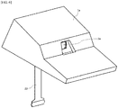
- FIG. 1 is an external perspective diagram when a camera for vehicle mounting, according the present embodiment, is viewed from the front face side.
- FIG. 2 is a perspective diagram wherein the vehicle-mounted camera according the present embodiment is viewed from the bottom side.
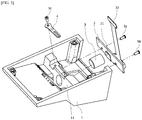
- FIG. 3 is an exploded perspective diagram wherein the vehicle-mounted camera according the present embodiment is viewed from the bottom side.
- FIG. 4 is a cross-sectional view of the lengthwise direction (the optical axial direction) of the vehicle-mounted camera in the form of the present embodiment.
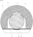
- FIG. 5 is an enlarged view of the B position in FIG. 4 .
- L indicates the optical axis.
- the camera for vehicle mounting is structured including an upper case 1 of a form that is integrated with the lens holder, a sensor substrate 2, a lens barrel 3, and a leaf spring 4.
- the upper case 1 is formed integrally with the lens holder 11.
- the state is one wherein the lens barrel 3 can be seen from the imaging subject side, from the opening portion that is formed in the upper case 1, a state wherein the sensor substrate 2, and the like, that are disposed within the upper case 1, cannot be seen.
- the upper case 1 is a case for covering the lens barrel 3 and the sensor substrate 2 of the camera for vehicle mounting according to the present embodiment, and is formed from a resin or a metal.
- the lens holder 11 for supporting the lens barrel 3 and the upper case 1 are structured separately; however the lens holder 11 according to the present embodiment is formed integrally with the upper case 1.
- An opening portion is formed in the upper case 1, structured so that light from the imaging subject will be incident, from the opening portion, into the lens barrel 3 that is supported by the lens holder 11.
- a cylindrical opening portion that is essentially parallel to the optical axis is formed in the lens holder 11, and assembled so that the lens barrel 3 is supported by the opening portion part.
- the lens barrel 3 is supported and secured in the lens holder 11 through radial fitting or screw.
- the sensor substrate 2 is a rigid substrate formed from resin, or the like, and a sensor 21, which functions as an imaging element, and other electronic component are mounted thereon.
- a connector that is connected to a flexible substrate 22 that has flexibility is further attached to the sensor substrate 2, and the sensor substrate 2 and the flexible substrate 22 are connected electrically through this connector.
- the flexible substrate 22 is used in order to connect the sensor substrate 2 and an external device electrically.
- the sensor 21 is a photoelectric converting element such as, for example, a CCD or a CMOS, or the like, and receives incident light from the imaging subject through the lens, to capture an image of the state of the imaging subject.
- a shutter may be disposed between the sensor 21 and the lens of the lens barrel 3.
- the image data captured by the sensor 21 is outputted through the flexible substrate 22 to an external device.
- the sensor substrate 2 is attached to a lens holder 11 of the upper case 1 through screws 5a and 5b. Some degree of gap (clearance) is formed in the screw openings for the screws 5a and 5b that are formed in the sensor substrate 2, thereby enabling a positional adjustment to the sensor 21, which is mounted on the sensor substrate 2, in the plane that is perpendicular to the optical axis.
- the lens barrel 3 is formed in a circular column shape so as to support and enclose one or more lenses.
- the lens barrel 3 is supported by the lens holder 11 while being biased toward the lens holder 11 by a leaf spring 4. More specifically, in the lens barrel 3, in a state wherein it is supported in the lens holder 11, a portion of the bottom side is exposed (referencing FIG. 3 through FIG. 5 ), where the center part of the leaf spring 4 contacts this exposed part.
- the leaf spring 4 through the above, biases the lens barrel 3 toward the top (the direction towards the lens holder 11), so that the lens barrel 3 is supported stably by the lens holder 11 through the biasing by the leaf spring 4. As shown in FIG. 3 , the leaf spring 4 is attached to the lens holder 11 through a screw 5c.
- the lens holder 11 and the upper case 1 are formed integrally, thus enabling a reduction in the number of components when compared to a structure wherein the lens holder 11 and the upper case 1 are structured separately, thereby enabling a reduction in costs. Moreover, the reduction in the number of components reduces the tolerance error variability for the component as a whole, enabling, for example, an increase the accuracy of the optical axial position.
- the structure is one wherein the leaf spring 4 is disposed to bias the lens barrel 3, enabling the lens barrel 3 to be secured and supported with stability on the lens holder 11. This enables suppression of the occurrence of misalignment of the optical axis.
- the camera for vehicle mounting according to the present invention when compared to the camera for vehicle mounting of the first embodiment, is dissimilar in the structure for supporting the lens barrel, but identical in the other structures.
- one distinctive feature is the point that the structure supports the lens barrel with greater stability than the camera for vehicle mounting according to the first embodiment.
- the structure of the camera for vehicle mounting according to the present embodiment will be explained in detail below.
- FIG. 6 is an external perspective diagram when a camera for vehicle mounting, according the present embodiment, is viewed from the front face side.
- FIG. 7 is a perspective diagram wherein the vehicle-mounted camera according the present embodiment is viewed from the bottom side.
- FIG. 8 is an exploded perspective diagram wherein the vehicle-mounted camera according the present embodiment is viewed from the bottom side.
- FIG. 9 is a cross-sectional diagram in the plane that is perpendicular to the optical axis of the vehicle-mounted camera according to the present embodiment. The plan view of FIG. 9 is an enlarged view at the position wherein the supporting part of the lens barrel 3 is seen easily.
- FIG. 10 is a cross-sectional view of the lengthwise direction (the optical axial direction) of the vehicle-mounted camera according to the present embodiment, and is a diagram corresponding to FIG. 5 (the enlarged view) of the first embodiment.
- L indicates the optical axis.
- the camera for vehicle mounting is structured including an upper case 1a of a form that is integrated with the lens holder, a sensor substrate 2, a lens barrel 3a, and a leaf spring 4a.
- the upper case 1a is formed integrally with the lens holder 11a.
- the state is one wherein the lens barrel 3 can be seen from the imaging subject side, from the opening portion that is formed in the upper case 1a, a state wherein the sensor substrate 2, and the like, that are disposed within the upper case 1a, cannot be seen.
- the upper case 1a has essentially the same structure as that of the upper case 1 of the first embodiment, but the structure of the lens holder 11a that is formed integrally is generally different.
- the lens holder 11a as depicted in FIG. 9 , in particular, is formed in a recessed and raised shape, through formation of raised portions 11b and 11c.
- the lens holder 11a has a shape wherein, when viewed in the cross-section (referencing FIG. 9 ), the raised portions 11b and 11c contact the lens barrel 3a at two points. Note that, as depicted in the cross-sectional view shown in FIG. 9 , a space 1b that is formed by the upper case 1a and the leaf spring 4a is shaped in essentially an inverted V shape.
- the lens barrel 3a is disposed in this space 1b.
- the leaf spring 4a is attached to the lens holder 11a through screws 5h and 5i (referencing FIG. 8 ), and, at the time of assembly, a portion thereof contacts the lens barrel 3a.
- a curved surface portion 41 a is formed in the leaf spring 4a, and is shaped so that, when viewed in the cross-section (referencing FIG. 9 ), one point of the curved surface portion 41 a is in contact with the lens barrel 3a.
- the leaf spring 4a in the same manner as in the first embodiment, biases the lens barrel 3a upward (in the direction wherein the lens barrel 3a is pressed toward the lens holder 11 a).
- the lens barrel 3a is secured at three points: the raised portions 11b and 11c of the lens holder 11a, and the curved surface portion 41a of the leaf spring 4a. Through this, the lens barrel 3a is supported with greater stability in the lens holder 11a.
- an aperture plate 4b for adjusting the amount of light that passes through at the time of imaging, is formed integrally with the leaf spring 4a in the present embodiment.
- the elastic body 4a and the aperture plate 4b are formed integrally in this way, the number of components can be reduced and the amount of assembly work can be reduced, when compared to a structure wherein the elastic body 4a is structured separately from the aperture plate 4b, thereby enabling a reduction in cost.
- the lens barrel 3a is formed in a circular column shape, and, as depicted in FIG. 8 and FIG. 10 , a recessed portion 31a is formed in the shape of a crosswise groove in the outer peripheral portion in the vicinity of the center portion thereof in the length direction.
- an elongated hole 42a is formed in the center part of the leaf spring 4a. In the state wherein the camera for vehicle mounting according to the present embodiment is assembled, the state is one wherein the recessed portion 31a of the lens barrel 3a can be seen from the elongated hole 42a of the leaf spring 4a.
- the tip end portion 61 of an eccentric pin 6 is inserted from the elongated hole 42a of the leaf spring 4a into the recessed portion 31a of the lens barrel 3a, where the eccentric pin 6 can be rotated to carry out focusing adjustment of the optical axis.
- FIG. 11 is a diagram showing the structure of the eccentric pin 6, which is a tool for adjusting the optical axis, used in focusing adjustment of the lens barrel 3a.
- the tip end portion 61 that is formed with a diameter that is narrower than that of the shaft portion protrudes from the shaft portion of the eccentric pin 6, where the tip end portion 61 has a different center from that of the shaft portion. Because of this, the distance of the lens barrel 3a from the sensor 21 is changed through an operator, who carries out the assembly operation at the time of assembly, rotating the eccentric pin 6 wherein the tip end portion 61 has been inserted into the recessed portion 31a of the lens barrel 3a, and the focusing adjustment of the optical axis can be performed thereby.
- the structure is such that the tip end portion 61 of the eccentric pin 6 can be inserted into the recessed portion 31 a of the lens barrel 3a from the elongated hole 42a of the leaf spring 4a after assembly.
- This enables the focusing adjustment of the optical axis to be carried out after assembly of the various structures in the camera for vehicle mounting according to the present embodiment.
- the elastic force of the leaf spring 4a can be adjusted by changing the size of the elongated hole 42a in the leaf spring 4a.
- this leaf spring may use another elastic body instead.
- a structure that uses a leaf spring made from metal is particularly preferred from the perspective of durability, or the like.
- the imaging element according to the present invention is used particularly effectively as an imaging device that is mounted onto a moving body, such as an automobile, which requires particularly high positional accuracy of the optical axis.
- the present invention can be used effectively as, for example, an imaging device for vehicle mounting that requires particularly high precision position adjustments. Explanation of Codes
Abstract
Description
- One form of the present invention relates to an imaging device able to perform position adjustment and position securing with good accuracy.
- As imaging devices used for vehicle-mounted cameras or monitoring cameras, there are those that comprises a lens barrel for arranging and holding a plurality of lenses, a lens holder for supporting the lens barrel, a printed circuit board (sensor substrate) whereon an imaging element is mounted, an upper case (housing) that supports the lens holder and that is connected to a vehicle body, or the like, and so forth. Such a conventional imaging device is disclosed in, for example,
Patent Document 1. - [Patent Document 1]
US Patent Application Publication 2014/0160284 , Specification - In a conventional imaging device, such as described above, from the perspective of ease of assembly, the lens holder and the upper case are formed as separate members. However, in, for example, vehicle-mounted cameras, and the like, of recent years, in products wherein it is necessary to secure the optical axial position with high accuracy, there has been a problem with variability in positioning between the lens holder and the upper case.
- The present invention adopts means such as the following in order to solve the problem described above. Note that while in the explanation below, reference symbols from the drawings are written parentheses for ease in understanding the present invention, the individual structural elements of the present invention are not limited to those that are written, but rather should be interpreted broadly, in a range that could be understood technically by a person skilled in the art.
- One means according to the present invention is:
an imaging device, comprising: - a lens barrel (3, 3a) for supporting, while enclosing, one or more lenses;
- an imaging element (21) for detecting light that passes through the lens;
- a lens holder (11, 11a) for supporting the lens barrel;
- an elastic body (4, 4a) that is disposed so as to bias the lens barrel relative to the lens holder; and
- an upper case (1, 1a) that is formed so as to enable connection with an external member, wherein:
the lens holder (11, 11a) and the upper case (1, 1a) are formed integrally. - In the imaging device according to the structure set forth above, the lens holder and the upper case are formed integrally, and thus when compared to a configuration wherein the lens holder and the upper case are structured separately, the number of components can be reduced, thereby enabling a reduction in costs. Moreover, the reduction in the number of components reduces the tolerance error variability for the component as a whole, enabling, for example, an increase the accuracy of the optical axial position. Moreover, because the structure is one wherein the elastic body is disposed so as to bias the lens barrel, it is possible to support the lens barrel with stability in the lens holder. This enables suppression of the occurrence of misalignment of the optical axis.
- In the imaging device set forth above, preferably:
the lens barrel (3a) is formed so as to contact the lens holder (11a) and contact the elastic body (4a). - Given the imaging device set forth above, the lens barrel is supported and secured by the lens holder and the elastic body, thus enabling a structure wherein the lens barrel can be supported with greater stability. Given this, this enables suppression of the occurrence of misalignment of the optical axis in the imaging element after assembly.
- Preferably, the lens barrel (3a) is formed so as to contact the lens holder (11a) at at least 2 points (and, more preferably, at 2 points), and so as to contact the elastic body (4a) at at least 1 point (and, more preferably, at 1 point). This structure enables the lens barrel to be supported and secured with greater stability.
- In the imaging device set forth above, preferably:
- a recessed portion (31a) for position adjustment is formed in the lens barrel (3a); and
- the recessed portion is visible.
- The imaging device set forth above enables a structure wherein a tool can be inserted into a recessed portion of the lens barrel from, for example, the hole (42a) of the elastic body after assembly of the imaging element. Through this, in the camera for vehicle mounting according the present embodiment, it is possible to perform focusing adjustment of the optical axis using the tool even after assembly of the various structures.
- In the imaging device set forth above, preferably:
the elastic body has an elongated hole. - The imaging device set forth above enables the elastic force that is applied to the elastic body to be adjusted through changing the size of the elongated hole that is formed in the elastic body.
- In the imaging device set forth above, preferably:
a groove-shaped recessed portion is formed, in the outer peripheral portion of the lens barrel, in a position that faces the elongated hole of the elastic body. - In the imaging device set forth above, preferably:
theelastic body 4a comprises, integrally, andaperture plate 4b for, for example, adjusting the amount of transmitted light, in using the imaging device (in imaging, or the like). - With the imaging device of this structure, the
elastic body 4a and theaperture plate 4b are formed integrally, and thus, when compared to a structure wherein theelastic body 4a and theaperture plate 4b are separate units, this can reduce the number of components and reduce the amount of assembly work, thereby enabling a reduction in costs, and the like. - Preferably the imaging device set forth above is mounted in a moving body.
- The imaging device set forth above enables proper adjustment of the optical axis, even in an imaging device for a moving body (for example, for vehicle mounting), that requires particularly high accuracy adjustment of the optical axis.
-
-
FIG. 1 is an external view of a camera for vehicle mounting according to a first embodiment. -
FIG. 2 is a diagram wherein the camera for vehicle mounting, according to the first embodiment, is viewed from below. -
FIG. 3 is an exploded view of a camera for vehicle mounting according to the first embodiment. -
FIG. 4 is a cross-sectional diagram of a camera for vehicle mounting according to the first embodiment. -
FIG. 5 is an enlarged cross-sectional diagram of a camera for vehicle mounting according to the first embodiment. -
FIG. 6 is an external view of a camera for vehicle mounting according to a second embodiment. -
FIG. 7 is a diagram wherein the camera for vehicle mounting, according to the second embodiment, is viewed from below. -
FIG. 8 is an exploded view of a camera for vehicle mounting according to the second embodiment. -
FIG. 9 is a cross-sectional diagram of a camera for vehicle mounting according to the second embodiment. -
FIG. 10 is an enlarged cross-sectional diagram of a camera for vehicle mounting according to the second embodiment. -
FIG. 11 is a diagram of an optical axis adjusting tool for a camera for vehicle mounting according to the second embodiment. - Embodiments according to the present invention will be explained in detail below, referencing the drawings, following the structures below. However, the embodiment explained below is no more than an example of the present invention, and must not be interpreted as limiting the technical scope of the present invention. Note that in the various drawings, identical reference symbols are assigned to identical structural elements, and explanations thereof may be omitted.
- 1.
Embodiment 1 - 2.
Embodiment 2 - 3. Supplementary Items
- The camera for vehicle mounting according to the present embodiment is an imaging device that is structured equipped with an upper case for vehicle mounting, and a distinctive feature is the point that the upper case and the lens holder are formed integrally. Moreover, another distinctive feature is the point that the lens barrel is biased by a lens spring in relation to the lens holder, and that the lens barrel is secured thereby. The structure of the camera for vehicle mounting according to the present embodiment will be explained in detail below.
-
FIG. 1 is an external perspective diagram when a camera for vehicle mounting, according the present embodiment, is viewed from the front face side. -
FIG. 2 is a perspective diagram wherein the vehicle-mounted camera according the present embodiment is viewed from the bottom side.FIG. 3 is an exploded perspective diagram wherein the vehicle-mounted camera according the present embodiment is viewed from the bottom side.FIG. 4 is a cross-sectional view of the lengthwise direction (the optical axial direction) of the vehicle-mounted camera in the form of the present embodiment.FIG. 5 is an enlarged view of the B position inFIG. 4 . InFIG. 4 andFIG. 5 , L indicates the optical axis. - As shown in
FIG. 1 through FIG. 5 (and, in particular, inFIG. 2 andFIG. 3 ), the camera for vehicle mounting according to the present embodiment is structured including anupper case 1 of a form that is integrated with the lens holder, asensor substrate 2, alens barrel 3, and aleaf spring 4. Theupper case 1 is formed integrally with thelens holder 11. In the assembled state, as shown inFIG. 1 , in particular, the state is one wherein thelens barrel 3 can be seen from the imaging subject side, from the opening portion that is formed in theupper case 1, a state wherein thesensor substrate 2, and the like, that are disposed within theupper case 1, cannot be seen. - The
upper case 1 is a case for covering thelens barrel 3 and thesensor substrate 2 of the camera for vehicle mounting according to the present embodiment, and is formed from a resin or a metal. In the conventional structure, thelens holder 11 for supporting thelens barrel 3 and theupper case 1 are structured separately; however thelens holder 11 according to the present embodiment is formed integrally with theupper case 1. An opening portion is formed in theupper case 1, structured so that light from the imaging subject will be incident, from the opening portion, into thelens barrel 3 that is supported by thelens holder 11. A cylindrical opening portion that is essentially parallel to the optical axis is formed in thelens holder 11, and assembled so that thelens barrel 3 is supported by the opening portion part. Thelens barrel 3 is supported and secured in thelens holder 11 through radial fitting or screw. - The
sensor substrate 2 is a rigid substrate formed from resin, or the like, and asensor 21, which functions as an imaging element, and other electronic component are mounted thereon. A connector that is connected to aflexible substrate 22 that has flexibility is further attached to thesensor substrate 2, and thesensor substrate 2 and theflexible substrate 22 are connected electrically through this connector. Theflexible substrate 22 is used in order to connect thesensor substrate 2 and an external device electrically. Thesensor 21 is a photoelectric converting element such as, for example, a CCD or a CMOS, or the like, and receives incident light from the imaging subject through the lens, to capture an image of the state of the imaging subject. Note that other structures, such as a cover lens, or the like, can be combined with thesensor 21, but such structures are also included in the "sensor 21" according to the present invention. Moreover, a shutter may be disposed between thesensor 21 and the lens of thelens barrel 3. The image data captured by thesensor 21 is outputted through theflexible substrate 22 to an external device. Thesensor substrate 2 is attached to alens holder 11 of theupper case 1 throughscrews screws sensor substrate 2, thereby enabling a positional adjustment to thesensor 21, which is mounted on thesensor substrate 2, in the plane that is perpendicular to the optical axis. - The
lens barrel 3 is formed in a circular column shape so as to support and enclose one or more lenses. The various lenses of thelens barrel 3, in the assembled state, refract, and direct to thesensor 21, the light that is incident from the imaging subject through the opening portion of theupper case 1. - The
lens barrel 3 is supported by thelens holder 11 while being biased toward thelens holder 11 by aleaf spring 4. More specifically, in thelens barrel 3, in a state wherein it is supported in thelens holder 11, a portion of the bottom side is exposed (referencingFIG. 3 through FIG. 5 ), where the center part of theleaf spring 4 contacts this exposed part. Theleaf spring 4, through the above, biases thelens barrel 3 toward the top (the direction towards the lens holder 11), so that thelens barrel 3 is supported stably by thelens holder 11 through the biasing by theleaf spring 4. As shown inFIG. 3 , theleaf spring 4 is attached to thelens holder 11 through ascrew 5c. - In this way, in the camera for vehicle mounting according to the present embodiment, the
lens holder 11 and theupper case 1 are formed integrally, thus enabling a reduction in the number of components when compared to a structure wherein thelens holder 11 and theupper case 1 are structured separately, thereby enabling a reduction in costs. Moreover, the reduction in the number of components reduces the tolerance error variability for the component as a whole, enabling, for example, an increase the accuracy of the optical axial position. - Moreover, in the camera for vehicle mounting according to the present embodiment, the structure is one wherein the
leaf spring 4 is disposed to bias thelens barrel 3, enabling thelens barrel 3 to be secured and supported with stability on thelens holder 11. This enables suppression of the occurrence of misalignment of the optical axis. - The camera for vehicle mounting according to the present invention, when compared to the camera for vehicle mounting of the first embodiment, is dissimilar in the structure for supporting the lens barrel, but identical in the other structures. In the camera for vehicle mounting according to the present embodiment, one distinctive feature is the point that the structure supports the lens barrel with greater stability than the camera for vehicle mounting according to the first embodiment. The structure of the camera for vehicle mounting according to the present embodiment will be explained in detail below.
-
FIG. 6 is an external perspective diagram when a camera for vehicle mounting, according the present embodiment, is viewed from the front face side. -
FIG. 7 is a perspective diagram wherein the vehicle-mounted camera according the present embodiment is viewed from the bottom side.FIG. 8 is an exploded perspective diagram wherein the vehicle-mounted camera according the present embodiment is viewed from the bottom side.FIG. 9 is a cross-sectional diagram in the plane that is perpendicular to the optical axis of the vehicle-mounted camera according to the present embodiment. The plan view ofFIG. 9 is an enlarged view at the position wherein the supporting part of thelens barrel 3 is seen easily.FIG. 10 is a cross-sectional view of the lengthwise direction (the optical axial direction) of the vehicle-mounted camera according to the present embodiment, and is a diagram corresponding toFIG. 5 (the enlarged view) of the first embodiment. InFIG. 10 , L indicates the optical axis. - As shown in
FIG. 5 through FIG. 10 (and, in particular, inFIG. 7 andFIG. 8 ), the camera for vehicle mounting according to the present embodiment is structured including anupper case 1a of a form that is integrated with the lens holder, asensor substrate 2, alens barrel 3a, and aleaf spring 4a. Theupper case 1a is formed integrally with thelens holder 11a. In the assembled state, as shown inFIG. 1 , in particular, the state is one wherein thelens barrel 3 can be seen from the imaging subject side, from the opening portion that is formed in theupper case 1a, a state wherein thesensor substrate 2, and the like, that are disposed within theupper case 1a, cannot be seen. - The
upper case 1a has essentially the same structure as that of theupper case 1 of the first embodiment, but the structure of thelens holder 11a that is formed integrally is generally different. Thelens holder 11a, as depicted inFIG. 9 , in particular, is formed in a recessed and raised shape, through formation of raisedportions lens holder 11a has a shape wherein, when viewed in the cross-section (referencingFIG. 9 ), the raisedportions lens barrel 3a at two points. Note that, as depicted in the cross-sectional view shown inFIG. 9 , aspace 1b that is formed by theupper case 1a and theleaf spring 4a is shaped in essentially an inverted V shape. Thelens barrel 3a is disposed in thisspace 1b. - On the other hand, the
leaf spring 4a is attached to thelens holder 11a throughscrews FIG. 8 ), and, at the time of assembly, a portion thereof contacts thelens barrel 3a. Acurved surface portion 41 a is formed in theleaf spring 4a, and is shaped so that, when viewed in the cross-section (referencingFIG. 9 ), one point of thecurved surface portion 41 a is in contact with thelens barrel 3a. Theleaf spring 4a, in the same manner as in the first embodiment, biases thelens barrel 3a upward (in the direction wherein thelens barrel 3a is pressed toward thelens holder 11 a). - In this way, the
lens barrel 3a is secured at three points: the raisedportions lens holder 11a, and thecurved surface portion 41a of theleaf spring 4a. Through this, thelens barrel 3a is supported with greater stability in thelens holder 11a. - Moreover, an
aperture plate 4b, for adjusting the amount of light that passes through at the time of imaging, is formed integrally with theleaf spring 4a in the present embodiment. When theelastic body 4a and theaperture plate 4b are formed integrally in this way, the number of components can be reduced and the amount of assembly work can be reduced, when compared to a structure wherein theelastic body 4a is structured separately from theaperture plate 4b, thereby enabling a reduction in cost. - Moreover, the
lens barrel 3a is formed in a circular column shape, and, as depicted inFIG. 8 andFIG. 10 , a recessedportion 31a is formed in the shape of a crosswise groove in the outer peripheral portion in the vicinity of the center portion thereof in the length direction. On the other hand, anelongated hole 42a is formed in the center part of theleaf spring 4a. In the state wherein the camera for vehicle mounting according to the present embodiment is assembled, the state is one wherein the recessedportion 31a of thelens barrel 3a can be seen from theelongated hole 42a of theleaf spring 4a. In the camera for vehicle mounting according to the present embodiment, after the variable structures have been assembled, thetip end portion 61 of aneccentric pin 6 is inserted from theelongated hole 42a of theleaf spring 4a into the recessedportion 31a of thelens barrel 3a, where theeccentric pin 6 can be rotated to carry out focusing adjustment of the optical axis. -
FIG. 11 is a diagram showing the structure of theeccentric pin 6, which is a tool for adjusting the optical axis, used in focusing adjustment of thelens barrel 3a. As depicted inFIG. 11 , thetip end portion 61 that is formed with a diameter that is narrower than that of the shaft portion protrudes from the shaft portion of theeccentric pin 6, where thetip end portion 61 has a different center from that of the shaft portion. Because of this, the distance of thelens barrel 3a from thesensor 21 is changed through an operator, who carries out the assembly operation at the time of assembly, rotating theeccentric pin 6 wherein thetip end portion 61 has been inserted into the recessedportion 31a of thelens barrel 3a, and the focusing adjustment of the optical axis can be performed thereby. - As described above, in the camera for vehicle mounting according to the present embodiment, the structure is such that the
tip end portion 61 of theeccentric pin 6 can be inserted into the recessedportion 31 a of thelens barrel 3a from theelongated hole 42a of theleaf spring 4a after assembly. This enables the focusing adjustment of the optical axis to be carried out after assembly of the various structures in the camera for vehicle mounting according to the present embodiment. Note that the elastic force of theleaf spring 4a can be adjusted by changing the size of theelongated hole 42a in theleaf spring 4a. - An embodiment according to the present invention was explained in detail above. The explanation above is no more than an explanation of one form of embodiment, and the scope of the present invention is not limited to this form of embodiment, but rather is interpreted broadly, in a scope that can be understood by one skilled in the art.
- For example, while, in the embodiments described above, the explanation was for a case wherein the
upper case 1 and thelens holder 11a were formed integrally, these structures may be formed through an arbitrary manufacturing method, such as injection molding, or the like. - While the various embodiments set forth above each used a leaf spring to secure the lens barrel, this leaf spring may use another elastic body instead. However, a structure that uses a leaf spring made from metal is particularly preferred from the perspective of durability, or the like.
- While in the various embodiments set forth above, the explanations were of structures wherein the
sensor 21 was mounted on thesensor substrate 2 and image data is transferred to the outside through aflexible substrate 22, this structure is not a part that is a distinctive feature according to the present invention, so another structure may be substituted. - While in the embodiments set forth above the explanations used a camera for vehicle mounting as an example, these cameras for vehicle mounting may also be used as typical imaging devices that are not for vehicle mounting. However, the imaging element according to the present invention is used particularly effectively as an imaging device that is mounted onto a moving body, such as an automobile, which requires particularly high positional accuracy of the optical axis.
- The present invention can be used effectively as, for example, an imaging device for vehicle mounting that requires particularly high precision position adjustments. Explanation of Codes
-
- 1, 1a: Upper Cases
- 1b: Space
- 11, 11a: Lens Holders
- 11b: Raised Portion
- 2: Sensor Substrate
- 21: Sensor
- 22: Flexible Substrate
- 3, 3a: Lens Barrels
- 31a: Recessed Portion
- 4, 4a: Leaf Springs
- 41a: Curved Surface Portion
- 42a: Elongated Hole
- 5a through 5i: Screws
- 6: Eccentric Pin
- 61: Tip End Portion
Claims (8)
- An imaging device, comprising:a lens barrel for supporting, while enclosing, one or more lenses;an imaging element for detecting light that passes through the lens;a lens holder for supporting the lens barrel;an elastic body that is disposed so as to bias the lens barrel relative to the lens holder;
andan upper case that is formed so as to enable connection with an external member, wherein:
the lens holder and the upper case are formed integrally. - An imaging device as set forth in Claim 1, wherein:
the lens barrel is formed so as to contact the lens holder and contact the elastic body. - An imaging device as set forth in Claim 2, wherein:
the lens barrel is formed so as to contact the lens holder at two points and to contact the elastic body at 1 point. - An imaging device as set forth in any one of Claim 1 through 3, wherein:a recessed portion for position adjustment is formed in the lens barrel; andthe recessed portion is visible.
- An imaging device as set forth in any one of Claim 1 through 4, wherein:
the elastic body has an elongated hole. - An imaging device as set forth in Claim 5, wherein:
a groove-shaped recessed portion is formed, in the outer peripheral portion of the lens barrel, in a position that faces the elongated hole of the elastic body. - An imaging device as set forth in any one of Claim 1 through 6, wherein:
an aperture plate that is structured integrally with the elastic body. - An imaging device as set forth in any one of Claim 1 through 7:
mounted on a moving body.
Applications Claiming Priority (2)
| Application Number | Priority Date | Filing Date | Title |
|---|---|---|---|
| JP2016093510A JP6731280B2 (en) | 2016-05-06 | 2016-05-06 | Imaging device |
| PCT/JP2017/016644 WO2017191797A1 (en) | 2016-05-06 | 2017-04-26 | Imaging device |
Publications (2)
| Publication Number | Publication Date |
|---|---|
| EP3454540A1 true EP3454540A1 (en) | 2019-03-13 |
| EP3454540A4 EP3454540A4 (en) | 2019-12-18 |
Family
ID=60202964
Family Applications (1)
| Application Number | Title | Priority Date | Filing Date |
|---|---|---|---|
| EP17792730.8A Withdrawn EP3454540A4 (en) | 2016-05-06 | 2017-04-26 | Imaging device |
Country Status (5)
| Country | Link |
|---|---|
| US (1) | US10793085B2 (en) |
| EP (1) | EP3454540A4 (en) |
| JP (1) | JP6731280B2 (en) |
| CN (1) | CN109076151B (en) |
| WO (1) | WO2017191797A1 (en) |
Families Citing this family (1)
| Publication number | Priority date | Publication date | Assignee | Title |
|---|---|---|---|---|
| US10506141B2 (en) * | 2017-05-19 | 2019-12-10 | Magna Electronics Inc. | Vehicle camera with cast resin sealing |
Family Cites Families (13)
| Publication number | Priority date | Publication date | Assignee | Title |
|---|---|---|---|---|
| US6897432B2 (en) * | 2001-03-20 | 2005-05-24 | Hewlett-Packard Development Company, L.P. | Imaging apparatus having discontinuous lens reference surfaces and method of assembling the imaging apparatus |
| JP4467298B2 (en) * | 2003-12-22 | 2010-05-26 | パナソニック株式会社 | Lens barrel |
| JP2006162803A (en) * | 2004-12-03 | 2006-06-22 | Seiko Precision Inc | Optical device and imaging apparatus |
| KR100766495B1 (en) * | 2005-12-19 | 2007-10-15 | 삼성전자주식회사 | Image pickup apparatus and data processing apparatus equipped with the image pickup apparatus |
| US20090015706A1 (en) * | 2007-04-24 | 2009-01-15 | Harpuneet Singh | Auto focus/zoom modules using wafer level optics |
| JP2009282328A (en) * | 2008-05-22 | 2009-12-03 | Tamron Co Ltd | Arrangement method of flexible printed circuit board in lens barrel of imaging apparatus, and imaging apparatus using flexible printed circuit board employing the arrangement method of flexible printed circuit board |
| CN102959447B (en) * | 2010-07-07 | 2015-05-20 | 松下电器(美国)知识产权公司 | Lens unit |
| JP6004637B2 (en) * | 2010-12-06 | 2016-10-12 | キヤノン株式会社 | LENS UNIT, IMAGE READING DEVICE, AND LENS UNIT MANUFACTURING METHOD |
| JP5316562B2 (en) * | 2011-02-10 | 2013-10-16 | 株式会社デンソー | Car camera |
| US8897633B2 (en) * | 2010-12-21 | 2014-11-25 | Denso Corporation | In-vehicle camera unit having camera built into body |
| DE112012003221B4 (en) * | 2011-08-02 | 2022-11-10 | Magna Electronics, Inc. | Vehicle camera system and method of assembling a vehicle camera system |
| US10511754B2 (en) * | 2014-08-01 | 2019-12-17 | Nidec Copal Corporation | Imaging apparatus, optical device, electronic device, vehicle, and imaging-device manufacturing method |
| JP2016039428A (en) * | 2014-08-06 | 2016-03-22 | 日立オートモティブシステムズ株式会社 | Imaging unit for on-vehicle camera and on-vehicle camera |
-
2016
- 2016-05-06 JP JP2016093510A patent/JP6731280B2/en active Active
-
2017
- 2017-04-26 EP EP17792730.8A patent/EP3454540A4/en not_active Withdrawn
- 2017-04-26 CN CN201780024010.0A patent/CN109076151B/en not_active Expired - Fee Related
- 2017-04-26 US US16/098,534 patent/US10793085B2/en active Active
- 2017-04-26 WO PCT/JP2017/016644 patent/WO2017191797A1/en unknown
Also Published As
| Publication number | Publication date |
|---|---|
| CN109076151B (en) | 2021-01-15 |
| JP2017201769A (en) | 2017-11-09 |
| WO2017191797A1 (en) | 2017-11-09 |
| US10793085B2 (en) | 2020-10-06 |
| CN109076151A (en) | 2018-12-21 |
| US20190135195A1 (en) | 2019-05-09 |
| EP3454540A4 (en) | 2019-12-18 |
| JP6731280B2 (en) | 2020-07-29 |
Similar Documents
| Publication | Publication Date | Title |
|---|---|---|
| US7492538B2 (en) | Camera module | |
| EP2933670A1 (en) | Lens module, method of manufacturing the same, and camera module including the same | |
| EP1932045B1 (en) | External adjustment mechanism for a camera lens and electronic imager | |
| EP1906395B1 (en) | Camera module | |
| KR20120057575A (en) | Lens tube, image pickup device, and portable terminal apparatus | |
| KR20080035417A (en) | Imaging apparatus | |
| TWI533044B (en) | Camera module | |
| JP7376279B2 (en) | Optical unit with shake correction function | |
| WO2020246465A1 (en) | Lens drive device, camera module, and camera-equipped device | |
| CN110959128A (en) | Image capturing apparatus | |
| JP2007322709A (en) | Optical member support mechanism, optical device, and interval adjustment member | |
| EP3454540A1 (en) | Imaging device | |
| US8866965B2 (en) | Imaging device for adjusting a distance between an image sensor and a lens | |
| JP2007041141A (en) | Lens retainer mechanism, lens position adjusting method, and camera module | |
| US7474412B2 (en) | Etalon device and manufacturing method thereof | |
| US10893180B2 (en) | Imaging device | |
| US20150301305A1 (en) | Lens drive apparatus and camera module | |
| EP2728851A1 (en) | Camera module | |
| JP2009139579A (en) | Lens barrel and imaging apparatus | |
| JP2017198755A (en) | Imaging apparatus | |
| KR20160103827A (en) | Camera Module | |
| CN112987453A (en) | Camera module | |
| JP6147096B2 (en) | Imaging device | |
| WO2018135454A1 (en) | Imaging device | |
| US8165464B2 (en) | Image pickup apparatus with AF sensor unit |
Legal Events
| Date | Code | Title | Description |
|---|---|---|---|
| STAA | Information on the status of an ep patent application or granted ep patent |
Free format text: STATUS: THE INTERNATIONAL PUBLICATION HAS BEEN MADE |
|
| PUAI | Public reference made under article 153(3) epc to a published international application that has entered the european phase |
Free format text: ORIGINAL CODE: 0009012 |
|
| STAA | Information on the status of an ep patent application or granted ep patent |
Free format text: STATUS: REQUEST FOR EXAMINATION WAS MADE |
|
| 17P | Request for examination filed |
Effective date: 20181114 |
|
| AK | Designated contracting states |
Kind code of ref document: A1 Designated state(s): AL AT BE BG CH CY CZ DE DK EE ES FI FR GB GR HR HU IE IS IT LI LT LU LV MC MK MT NL NO PL PT RO RS SE SI SK SM TR |
|
| AX | Request for extension of the european patent |
Extension state: BA ME |
|
| STAA | Information on the status of an ep patent application or granted ep patent |
Free format text: STATUS: REQUEST FOR EXAMINATION WAS MADE |
|
| DAV | Request for validation of the european patent (deleted) | ||
| DAX | Request for extension of the european patent (deleted) | ||
| A4 | Supplementary search report drawn up and despatched |
Effective date: 20191120 |
|
| RIC1 | Information provided on ipc code assigned before grant |
Ipc: G02B 7/04 20060101ALI20191114BHEP Ipc: G03B 15/00 20060101ALI20191114BHEP Ipc: H04N 5/225 20060101AFI20191114BHEP Ipc: G03B 17/02 20060101ALI20191114BHEP Ipc: G02B 7/02 20060101ALI20191114BHEP |
|
| STAA | Information on the status of an ep patent application or granted ep patent |
Free format text: STATUS: THE APPLICATION HAS BEEN WITHDRAWN |
|
| 18W | Application withdrawn |
Effective date: 20210618 |