JP2007322709A - Optical member support mechanism, optical device, and interval adjustment member - Google Patents
Optical member support mechanism, optical device, and interval adjustment member Download PDFInfo
- Publication number
- JP2007322709A JP2007322709A JP2006152374A JP2006152374A JP2007322709A JP 2007322709 A JP2007322709 A JP 2007322709A JP 2006152374 A JP2006152374 A JP 2006152374A JP 2006152374 A JP2006152374 A JP 2006152374A JP 2007322709 A JP2007322709 A JP 2007322709A
- Authority
- JP
- Japan
- Prior art keywords
- lens
- optical
- optical axis
- holding member
- support
- Prior art date
- Legal status (The legal status is an assumption and is not a legal conclusion. Google has not performed a legal analysis and makes no representation as to the accuracy of the status listed.)
- Pending
Links
Images


Classifications
-
- G—PHYSICS
- G02—OPTICS
- G02B—OPTICAL ELEMENTS, SYSTEMS OR APPARATUS
- G02B7/00—Mountings, adjusting means, or light-tight connections, for optical elements
- G02B7/02—Mountings, adjusting means, or light-tight connections, for optical elements for lenses
- G02B7/021—Mountings, adjusting means, or light-tight connections, for optical elements for lenses for more than one lens
-
- G—PHYSICS
- G02—OPTICS
- G02B—OPTICAL ELEMENTS, SYSTEMS OR APPARATUS
- G02B7/00—Mountings, adjusting means, or light-tight connections, for optical elements
- G02B7/02—Mountings, adjusting means, or light-tight connections, for optical elements for lenses
- G02B7/023—Mountings, adjusting means, or light-tight connections, for optical elements for lenses permitting adjustment
Abstract
Description
この発明は、光学部材支持機構、光学装置、および間隔調整部材に関する。 The present invention relates to an optical member support mechanism, an optical device, and a distance adjusting member.
従来より、たとえば、レンズなどの複数の光学部材が1つの光軸上に配置された光学装置がある。このような光学装置を、たとえば、部品を単純に組み立てること(以下、「単純組み立て」という)によって製造する場合、光学装置を構成する各部品の製造精度が、光学装置の光学精度として直接反映されるため、各部品の製造精度が高精度に維持されるように管理する必要がある。 Conventionally, for example, there is an optical device in which a plurality of optical members such as lenses are arranged on one optical axis. When such an optical device is manufactured, for example, by simply assembling components (hereinafter referred to as “simple assembly”), the manufacturing accuracy of each component constituting the optical device is directly reflected as the optical accuracy of the optical device. Therefore, it is necessary to manage such that the manufacturing accuracy of each component is maintained with high accuracy.
単純組み立てによって製造される光学装置では、たとえば、光学装置の光学性能の向上や小型化などにともなって、各部品に要求される製造精度が高くなるほど、各部品の製造にかかる歩留まりが低下し、これによって光学装置の製造の歩留まりが低下したり、光学装置の製造コストが増加したりすることが懸念される。 In an optical device manufactured by simple assembly, for example, as the optical performance of the optical device is improved or reduced in size, the higher the manufacturing accuracy required for each component, the lower the yield for manufacturing each component. As a result, there is a concern that the manufacturing yield of the optical device may decrease, or the manufacturing cost of the optical device may increase.
このため、従来より、光学装置における各光学部材の光軸が1つの光軸上に配置されるように、任意の光学部材の光軸の傾きを調整する各種の技術がある。たとえば、任意のレンズを保持するレンズ保持枠とレンズ保持枠が取り付けられる取付部材との間に、ワッシャーなどの間隔調整部材を設けることで任意のレンズの光軸の傾きを調整するようにした技術がある。 For this reason, conventionally, there are various techniques for adjusting the inclination of the optical axis of an arbitrary optical member so that the optical axes of the optical members in the optical apparatus are arranged on one optical axis. For example, a technology that adjusts the inclination of the optical axis of an arbitrary lens by providing an interval adjusting member such as a washer between a lens holding frame that holds an arbitrary lens and an attachment member to which the lens holding frame is attached. There is.
また、たとえば、レンズを保持するレンズ保持枠とレンズ保持枠が取り付けられる取付部材との間に、レンズ保持枠の外周部分に沿ってレンズ保持枠に当接する単一の圧縮コイルバネを設け、レンズの中心を間にして対向する2箇所でレンズ保持枠を取付部材にネジ止めするようにした技術がある(たとえば、下記特許文献1参照。)。 In addition, for example, a single compression coil spring that contacts the lens holding frame along the outer peripheral portion of the lens holding frame is provided between the lens holding frame that holds the lens and the mounting member to which the lens holding frame is attached. There is a technique in which the lens holding frame is screwed to the mounting member at two locations facing each other with the center in between (see, for example, Patent Document 1 below).
また、たとえば、取付部材への取付対象となる鏡の鏡面とは裏面側に複数のコイルバネを設け、鏡の周縁部分の複数箇所をネジ止めするようにした技術がある(たとえば、下記特許文献2参照。)。特許文献1,2に記載された技術では、ネジの締め付け量を調整することによって、調整対象となるレンズの光軸の傾きを調整する。 Further, for example, there is a technique in which a plurality of coil springs are provided on the back side of the mirror surface of the mirror to be attached to the mounting member, and a plurality of peripheral portions of the mirror are screwed (for example, Patent Document 2 below). reference.). In the techniques described in Patent Documents 1 and 2, the inclination of the optical axis of the lens to be adjusted is adjusted by adjusting the tightening amount of the screw.
しかしながら、上述した従来技術のうち間隔調整部材を設けるようにした技術では、調整する箇所数に応じて間隔調整部材の数が増加するため、部品点数が増加するという問題がある。また、この技術では、間隔調整部材を設けるためには、既に取り付けられているレンズ保持枠を一旦取り外さなくてはならず、調整作業が繁雑であるという問題がある。 However, the technique in which the interval adjusting member is provided among the above-described conventional techniques has a problem that the number of parts increases because the number of the interval adjusting members increases according to the number of locations to be adjusted. In addition, in this technique, in order to provide the interval adjusting member, the lens holding frame that has already been attached has to be removed once, and there is a problem that adjustment work is complicated.
また、上述した従来技術のうち特許文献1に記載された技術では、単一の圧縮コイルバネを用いていることから、ネジごとの締め付け量によって圧縮コイルバネの圧縮状態に部分ごとの偏りが生じ、圧縮コイルバネからレンズ保持部材に加えられる付勢力に偏りが生じて、レンズ保持枠を安定して取り付けることができないという問題がある。 Moreover, in the technique described in Patent Document 1 among the above-described prior arts, since a single compression coil spring is used, the compression state of the compression coil spring is caused by the amount of tightening for each screw, resulting in partial bias. There is a problem in that the biasing force applied from the coil spring to the lens holding member is biased, and the lens holding frame cannot be stably attached.
また、上述した従来技術のうち特許文献2に記載された技術では、たとえば、調整精度を向上させるために、ネジ止めする箇所(以下、「調整箇所」という)を増やした場合、調整箇所の増加にともなってコイルバネの数が増加するため、調整精度の向上にともなって部品点数が増加し、調整作業が繁雑になるという問題がある。 Moreover, in the technique described in Patent Document 2 among the above-described prior arts, for example, when the number of locations to be screwed (hereinafter referred to as “adjustment locations”) is increased in order to improve adjustment accuracy, the number of adjustment locations increases. Accordingly, since the number of coil springs increases, there is a problem that the number of parts increases as the adjustment accuracy improves, and the adjustment work becomes complicated.
この発明は、上述した従来技術による問題点を解消するため、光学部材を安定して取り付けるとともに、光学部材の取付状態を容易に調整することができる光学部材支持機構、光学装置、および間隔調整部材を提供することを目的とする。 In order to solve the above-described problems caused by the prior art, the present invention provides an optical member support mechanism, an optical device, and a distance adjustment member that can stably attach an optical member and easily adjust the attachment state of the optical member. The purpose is to provide.
この発明にかかる光学部材支持機構は、光軸上に配置される複数の光学部材のうち任意の光学部材を保持する保持部材と、前記光軸方向において前記保持部材に対向する取付面を有する支持部材と、前記保持部材を前記支持部材に取り付ける取付手段と、前記取付手段によって取り付けられる前記保持部材と前記支持部材との間に設けられる間隔調整部材と、を備え、前記間隔調整部材は、前記保持部材および前記支持部材に対して、前記保持部材と前記支持部材とが相対的に離反する方向への付勢力を作用させることを特徴とする。 The optical member support mechanism according to the present invention is a support having a holding member that holds an arbitrary optical member among a plurality of optical members arranged on the optical axis, and a mounting surface that faces the holding member in the optical axis direction. A member, an attaching means for attaching the holding member to the support member, and an interval adjusting member provided between the holding member and the supporting member attached by the attaching means, wherein the interval adjusting member is An urging force is applied to the holding member and the support member in a direction in which the holding member and the support member are relatively separated from each other.
この発明によれば、組み立てに際して保持部材と支持部材との間に間隔調整部材を介在させるだけで、支持部材に対する保持部材のがたつきを抑えることができるので、光学部材を安定して取り付けることができる。 According to this invention, since the rattling of the holding member with respect to the support member can be suppressed only by interposing the gap adjusting member between the holding member and the support member during assembly, the optical member can be stably attached. Can do.
また、この発明によれば、保持部材と支持部材との間に間隔調整部材を介在させている間は支持部材に対する保持部材のがたつきを抑えることができるので、支持部材に保持部材を取り付けたままで、光学部材の取付状態を容易に調整することができる。 Further, according to the present invention, since the holding member can be prevented from rattling with respect to the support member while the interval adjusting member is interposed between the holding member and the support member, the holding member is attached to the support member. It is possible to easily adjust the mounting state of the optical member.
また、この発明にかかる光学部材支持機構における前記間隔調整部材は、前記間隔調整部材の一部を前記保持部材側および前記取付面の少なくとも一方側へ屈曲させた曲げ部を備え、当該曲げ部の弾性によって前記付勢力を作用させることを特徴とする。 Further, the interval adjusting member in the optical member supporting mechanism according to the present invention includes a bent portion obtained by bending a part of the interval adjusting member toward at least one side of the holding member side and the mounting surface. The biasing force is applied by elasticity.
この発明によれば、間隔調整部材に一体に設けられた曲げ部によって支持部材に対する保持部材のがたつきを抑えることができるので、少ない部品数および少ない組み立て工程数で、光学部材を安定して取り付けることができる。 According to the present invention, since the bend portion provided integrally with the interval adjusting member can suppress the rattling of the holding member with respect to the support member, the optical member can be stably provided with a small number of parts and a small number of assembly steps. Can be attached.
また、この発明によれば、間隔調整部材の製造に際して曲げ部を同時に製造することができるので、間隔調整部材を容易に製造することができる。 Moreover, according to this invention, since a bending part can be manufactured simultaneously in the case of manufacture of a space | interval adjustment member, a space | interval adjustment member can be manufactured easily.
また、この発明にかかる光学部材支持機構における前記取付手段は、前記取付面内の取付位置で前記光軸方向に挿抜されるピン状部材および挿入孔を備え、前記挿入孔に対する前記ピン状部材の挿入状態に応じて前記光軸方向における前記保持部材と前記取付面との距離を変化させることを特徴とする。 Further, the attachment means in the optical member support mechanism according to the present invention includes a pin-like member and an insertion hole that are inserted and removed in the optical axis direction at an attachment position within the attachment surface, and the pin-like member with respect to the insertion hole The distance between the holding member and the mounting surface in the optical axis direction is changed according to the insertion state.
この発明によれば、挿入孔に対するピン状部材の挿入状態を調整することで、光学部材支持機構の組み立て後に支持部材から保持部材を取り外すことなく、光学部材の取付状態を容易に調整することができる。 According to this invention, by adjusting the insertion state of the pin-shaped member with respect to the insertion hole, it is possible to easily adjust the attachment state of the optical member without removing the holding member from the support member after the assembly of the optical member support mechanism. it can.
また、この発明にかかる光学部材支持機構における前記取付位置は、前記光軸周りに複数存在し、前記曲げ部は、前記各取付位置の近傍に設けられていることを特徴とする。 In the optical member support mechanism according to the present invention, there are a plurality of attachment positions around the optical axis, and the bending portion is provided in the vicinity of each attachment position.
この発明によれば、挿入孔に対するピン状部材の挿入状態を取付位置ごとに調整することで保持部材が保持する光学部材の光軸の向きを調整することができ、調整後には各取付位置ごとに付勢力を作用させることができるので、光学部材を安定して取り付けるとともに、光学部材の取付状態を容易かつ高精度に調整することができる。 According to the present invention, the orientation of the optical axis of the optical member held by the holding member can be adjusted by adjusting the insertion state of the pin-shaped member with respect to the insertion hole for each attachment position. Since the urging force can be applied to the optical member, it is possible to stably attach the optical member and easily and accurately adjust the attachment state of the optical member.
また、この発明にかかる光学部材支持機構における前記取付位置は、前記光軸周りに複数存在し、前記曲げ部は、前記取付位置のうち前記光軸周りに隣り合う取付位置の中間に設けられていることを特徴とする。 In the optical member support mechanism according to the present invention, there are a plurality of attachment positions around the optical axis, and the bending portion is provided between the attachment positions adjacent to the circumference of the optical axis. It is characterized by being.
この発明によれば、保持部材と取付面との光軸方向における距離を取付位置ごとに調整することで保持部材が保持する光学部材の光軸の向きを調整することができ、調整後には隣り合う取付位置に対して均等に付勢力を作用させることができるので、光学部材を安定して取り付けるとともに、光学部材の取付状態を容易かつ高精度に調整することができる。 According to this invention, the direction of the optical axis of the optical member held by the holding member can be adjusted by adjusting the distance in the optical axis direction between the holding member and the mounting surface for each mounting position. Since the urging force can be applied evenly to the fitting position, the optical member can be stably attached and the attachment state of the optical member can be adjusted easily and with high accuracy.
また、この発明にかかる光学部材支持機構において、前記取付位置は、3つであることを特徴とする。 In the optical member support mechanism according to the present invention, the attachment positions are three.
この発明によれば、取付位置の数を必要最小限とした上で、光学部材を安定して取り付けるとともに、光学部材の取付状態を容易かつ高精度に調整することができる。 According to this invention, it is possible to stably attach the optical member and adjust the attachment state of the optical member easily and with high accuracy while minimizing the number of attachment positions.
また、この発明にかかる光学部材支持機構は、光軸上に配置される複数の光学部材のうち任意の光学部材を保持する保持部材と、前記光軸方向において前記保持部材に対向する取付面を有する支持部材と、前記保持部材を前記支持部材に取り付ける取付手段と、を備え、前記保持部材および前記支持部材の少なくとも一方は、前記支持部材および前記保持部材の少なくとも一方に対して、前記保持部材と前記支持部材とが離反する方向への付勢力を作用させることを特徴とする。 The optical member support mechanism according to the present invention includes a holding member that holds an arbitrary optical member among a plurality of optical members arranged on the optical axis, and a mounting surface that faces the holding member in the optical axis direction. And a mounting means for attaching the holding member to the support member, wherein at least one of the holding member and the support member is in relation to at least one of the support member and the holding member. And an urging force in a direction in which the support member and the support member are separated from each other.
この発明によれば、支持部材に対して保持部材を取り付けるだけで、支持部材に対する保持部材のがたつきを抑えることができるので、光学部材を容易かつ安定して取り付けることができる。 According to this invention, it is possible to suppress the rattling of the holding member with respect to the support member only by attaching the holding member to the support member, so that the optical member can be easily and stably attached.
また、この発明によれば、支持部材に対して保持部材が取り付けられている間は支持部材に対する保持部材のがたつきを抑えることができるので、支持部材に保持部材を取り付けたままで、光学部材の取付状態を容易に調整することができる。 Further, according to the present invention, the rattling of the holding member with respect to the support member can be suppressed while the holding member is attached to the support member, so that the optical member can be kept attached to the support member. Can be easily adjusted.
また、この発明にかかる光学部材支持機構における前記保持部材および前記支持部材の少なくとも一方は、前記保持部材および前記支持部材の少なくとも一方の一部を前記支持部材側または前記取付面側へ屈曲させた曲げ部を備え、当該曲げ部の弾性によって前記付勢力を作用させることを特徴とする。 In the optical member support mechanism according to the present invention, at least one of the holding member and the support member has a part of at least one of the holding member and the support member bent toward the support member or the mounting surface. A bending portion is provided, and the urging force is applied by the elasticity of the bending portion.
この発明によれば、光学部材支持機構の組み立てに際しては、支持部材に対して保持部材を取り付けるだけで支持部材に対する保持部材のがたつきを抑えることができるので、少ない組み立て工程数で光学部材を安定して取り付けることができる。 According to the present invention, when assembling the optical member support mechanism, it is possible to suppress rattling of the holding member with respect to the support member simply by attaching the holding member to the support member. Can be attached stably.
また、この発明にかかる光学部材支持機構における前記曲げ部は、前記保持部材および前記支持部材の少なくとも一方に一体に成型されていることを特徴とする。 In the optical member support mechanism according to the present invention, the bent portion is formed integrally with at least one of the holding member and the support member.
この発明によれば、支持部材に対して保持部材を取り付けるだけで、新たな部品および当該部品を組み込む作業をおこなうことなく、支持部材に対する保持部材のがたつきを抑えることができるので、少ない部品数および少ない組み立て工程数で、光学部材を安定して取り付けることができる。 According to the present invention, it is possible to suppress the rattling of the holding member with respect to the support member by simply attaching the holding member to the support member, and without performing the work of incorporating a new part and the part. The optical member can be stably attached with a small number and a small number of assembly steps.
また、この発明にかかる光学装置は、上述した光学部材支持機構によって支持される光学部材を備えることを特徴とする。 An optical device according to the present invention includes an optical member supported by the optical member support mechanism described above.
この発明によれば、光学部材のがたつきを抑え、光学部材を安定して取り付けるとともに、光学部材の取付状態を容易に調整することができる。 According to this invention, shakiness of the optical member can be suppressed, the optical member can be stably attached, and the attachment state of the optical member can be easily adjusted.
また、この発明にかかる間隔調整部材は、光軸上に配置される複数の光学部材のうち任意の光学部材を保持する保持部材と、前記光軸方向において前記保持部材に対向する取付面を有する支持部材と、の間に設けられる間隔調整部材であって、前記間隔調整部材の一部を前記保持部材側および前記取付面の少なくとも一方側へ屈曲させた曲げ部を備え、当該曲げ部の弾性によって、前記支持部材および前記保持部材に対して、前記保持部材と前記支持部材とが離反する方向への付勢力を作用させることを特徴とする。 Moreover, the space | interval adjustment member concerning this invention has a holding member holding arbitrary optical members among the some optical members arrange | positioned on an optical axis, and a mounting surface facing the said holding member in the said optical axis direction. An interval adjusting member provided between the support member and a bending portion formed by bending a part of the interval adjusting member toward at least one side of the holding member side and the mounting surface. Thus, an urging force is applied to the support member and the holding member in a direction in which the holding member and the support member are separated from each other.
この発明によれば、保持部材と支持部材における取付面との間に間隔調整部材を位置づけた状態で支持部材に対して保持部材を取り付けることで、支持部材に対する保持部材のがたつきを抑えて、光学部材を安定して取り付けさせることができる。 According to the present invention, the holding member is attached to the support member in a state in which the gap adjusting member is positioned between the holding member and the mounting surface of the support member, thereby suppressing rattling of the holding member with respect to the support member. The optical member can be stably attached.
また、この発明によれば、保持部材と支持部材との間に間隔調整部材を介在させている間は支持部材に対する保持部材のがたつきを抑えることができるので、支持部材に保持部材を取り付けたままで、光学部材の取付状態を容易に調整することができる。 Further, according to the present invention, since the holding member can be prevented from rattling with respect to the support member while the interval adjusting member is interposed between the holding member and the support member, the holding member is attached to the support member. It is possible to easily adjust the mounting state of the optical member.
この発明にかかる光学部材支持機構、光学装置、および間隔調整部材によれば、光学部材を安定して取り付けるとともに、光学部材の取付状態を容易に調整することができる。 According to the optical member support mechanism, the optical device, and the interval adjustment member according to the present invention, the optical member can be stably attached and the attachment state of the optical member can be easily adjusted.
以下に添付図面を参照して、この発明にかかる光学部材支持機構、光学装置、および間隔調整部材の好適な実施の形態を詳細に説明する。この実施の形態は、この発明にかかる光学部材支持機構、光学装置、および間隔調整部材を実現するズームレンズ装置への適用例を示す。 Exemplary embodiments of an optical member support mechanism, an optical device, and a distance adjusting member according to the present invention will be explained below in detail with reference to the accompanying drawings. This embodiment shows an application example to a zoom lens device that realizes an optical member support mechanism, an optical device, and a distance adjusting member according to the present invention.
(実施の形態1)
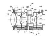
図1は、実施の形態1のズームレンズ装置を示す断面図である。はじめに、図1を用いて、実施の形態1のズームレンズ装置の構成について説明する。図1に示したように、実施の形態1のズームレンズ装置100は、一連の光軸上に設けられた複数のレンズ101〜105を備えている。複数のレンズ101〜105のうち、図1中符号101であらわしたレンズ(以下、「L5レンズ」という)は、L5レンズ移動枠106によって保持されている。L5レンズ101は、鏡筒107内に設けられている。
(Embodiment 1)
FIG. 1 is a cross-sectional view illustrating the zoom lens device according to the first embodiment. First, the configuration of the zoom lens apparatus according to the first embodiment will be described with reference to FIG. As shown in FIG. 1, the
鏡筒107は、ズームレンズ装置100の光軸方向を軸芯方向とする略円筒形状を有しており、マウント108に取り付けられる第1の鏡筒109と、第1の鏡筒109に取り付けられる第2の鏡筒110と、を備えている。第2の鏡筒110は、第1の鏡筒109を間にしてマウント108とは反対側に設けられている。実施の形態1では、第2の鏡筒110によって支持部材が実現されている。
The
L5レンズ移動枠106は、光軸方向にのみ移動可能に設けられている。L5レンズ移動枠106は、一部が第1の鏡筒109の外部に位置づけられており、第1の鏡筒109の外部に設けられたシャフト111に連結されている。シャフト111は、光軸方向に延出する棒形状を有している。シャフト111の外周面にはネジ山が設けられている。上述したL5レンズ移動枠106は、シャフト111に設けられたネジ山に、自身に設けられたネジ山を螺合させることで、シャフト111に連結されている。
The L5
シャフト111の一端部には、シャフト111をシャフト111の軸芯回りに回転させるモータ112が設けられている。モータ112が回転し、シャフト111が回転すると、シャフト111に連結されたL5レンズ移動枠106がシャフト111のネジ山に沿って移動する。L5レンズ移動枠106は、モータ112の回転方向に応じた方向に移動する。これによって、L5レンズ101を光軸方向に移動させることができる。L5レンズ101の光軸方向における位置は、光学センサ113からの出力値に基づいて検出する。
A
複数のレンズ101〜105のうち、図1中符号102であらわしたレンズ(以下、「L4レンズ」という)は、第1の鏡筒109によって保持されている。第1の鏡筒109には、L4レンズ102を間にしてL5レンズ101とは反対側に位置づけられた絞り羽根114aを有する絞りユニット114が設けられている。
Among the plurality of
絞り羽根114aは、開口量を変化させることが可能な構成を有している。公知の技術であるため、絞り羽根114aの構成については説明を省略するが、絞り羽根114aとしては、具体的には、たとえば、光彩絞り羽根などを用いることができる。絞りユニット114は、L4レンズ102の明るさ調整に際して、絞り羽根114aを駆動制御して、絞り羽根114aの開口量を変化させる。
The
また、複数のレンズ101〜105のうち、図1中符号103であらわしたレンズ(以下、「L3レンズ」という)は、第2の鏡筒110内に設けられており、L3レンズ移動枠115によって保持されている。L3レンズ移動枠115は、光軸方向にのみ移動可能に設けられている。L3レンズ移動枠115は、一部が第2の鏡筒110の外部に位置づけられており、第2の鏡筒110の外部に設けられたシャフト116に連結されている。
Further, among the plurality of
シャフト116は、上述したシャフト111と同様に、光軸方向に延出する棒形状を有しており、外周面にはネジ山が設けられている。L3レンズ移動枠115は、シャフト116に設けられたネジ山に、自身に設けられたネジ山を螺合させることで、シャフト116に連結されている。
The
シャフト116の一端部には、シャフト116をシャフト116の軸芯回りに回転させるモータ117が設けられている。上述したL5レンズ移動枠106の移動方法と同様に、モータ117が回転してシャフト116が回転すると、シャフト116に連結されたL3レンズ移動枠115がシャフト116のネジ山に沿って移動するので、L3レンズ103を光軸方向に移動させることができる。L3レンズ103の光軸方向における位置は、光学センサ118からの出力値に基づいて検出する。
A
また、複数のレンズ101〜105のうち、図1中符号104,105であらわしたレンズ(以下、それぞれ「L2レンズ」,「l1レンズ」という)は、保持部材としての固定レンズ保持枠119によって保持されている。固定レンズ保持枠119は、第2の鏡筒110における第1の鏡筒109とは反対側に設けられている。
Further, among the plurality of
固定レンズ保持枠119は、第2の鏡筒110に対してピン状部材としての調整ネジ120を用いて、第2の鏡筒110に取り付けられている。調整ネジ120は、ズームレンズ装置100の光軸を中心とする同心円上に等間隔で点在する3箇所で、第2の鏡筒110に設けられた挿入孔としてのネジ穴121に螺合される。実施の形態1では、調整ネジ120およびネジ穴121によって取付手段が実現されている。固定レンズ保持枠119と第2の鏡筒110との間には、間隔調整部材としての倒れ間隔調整板122が設けられている。
The fixed
倒れ間隔調整板122は、金属あるいはエンジニアリングプラスチックなどを用いて形成することができる。エンジニアリングプラスチックとして、具体的には、たとえば、ポリカーボネート、PPSなどが挙げられる。倒れ間隔調整板122は、所定範囲内の強さの外力が加えられて変形した場合に、元の形状に復帰可能な弾性を有している。
The fall
実施の形態1では、複数のレンズ101〜105によって光学部材が実現され、そのうちl1レンズ105およびL2レンズ104によって任意の光学部材が実現されている。なお、光軸上に配置される光学部材としては、L5レンズ移動枠106,鏡筒107,絞り羽根114a,L3レンズ移動枠115であってもよい。
In the first embodiment, an optical member is realized by the plurality of
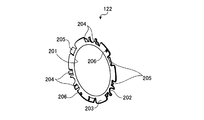
図2は、倒れ間隔調整板122を示す斜視図である。つぎに、図2を用いて、倒れ間隔調整板122について説明する。図2に示したように、倒れ間隔調整板122は、固定レンズ保持枠119が挿入される円形状の開口部201を中央に備える平板状の部材である。開口部201は、ズームレンズ装置100の光軸を中心とする円形状に設けられている。倒れ間隔調整板122には、第2の鏡筒110に設けられたネジ穴121の縁部(図3を参照)を回避する凹部202が設けられている。
FIG. 2 is a perspective view showing the fall
倒れ間隔調整板122は、開口部201の外縁部に設けられた基部203および曲げ部204,205を備えている。基部203は、ズームレンズ装置100の光軸に直交する面内で、開口部201の中心から離反する方向に張り出している。曲げ部204,205は、ズームレンズ装置100の光軸に直交する面から固定レンズ保持枠119側へ屈曲した形状を有している。
The fall
曲げ部204,205は、開口部201の中心から離反するほど固定レンズ保持枠119側に位置づけられるように屈曲した形状を有している。曲げ部204は、各凹部202の近傍に設けられている。また、曲げ部204は、開口部201の中心を中心とする同一円周上で、各凹部202の両隣となる位置にそれぞれ設けられている。すべての曲げ部204は、大きさおよび固定レンズ保持枠119側への屈曲角度がすべて等しくなるように形成されている。
The
曲げ部205は、開口部201の中心を中心とする同一の円上で、隣り合う凹部202の中間に設けられている。また、曲げ部205は、開口部201の中心を中心とする同一の円上に等間隔で点在する3箇所に設けられている。すべての曲げ部205は、大きさおよび固定レンズ保持枠119側への屈曲角度がすべて等しくなるように形成されている。
The
実施の形態1では、曲げ部205の大きさは、曲げ部204の大きさよりも大きいが、曲げ部204,205の大小関係は、図2に示した大小関係に限るものではなく、倒れ間隔調整板122が取り付けられる箇所の形状などに応じて適宜最適な大きさに設計することができる。
In the first embodiment, the size of the
曲げ部205の固定レンズ保持枠119側への屈曲角度は、曲げ部204の固定レンズ保持枠119側への屈曲角度と等しい。また、倒れ間隔調整板122には、第2の鏡筒110に設けられた位置決めピン(図3参照)が挿入される位置決め穴206が設けられている。
The bending angle of the
図3は、ズームレンズ装置100の一部を示す分解斜視図である。図3中、符号301は上述した位置決め穴206に挿入される位置決めピンであり、符号302は上述したネジ穴121の縁部である。倒れ間隔調整板122は、位置決めピン301が位置決め穴206に挿入されることで、第2の鏡筒110に対して位置決めされる。
FIG. 3 is an exploded perspective view showing a part of the
実施の形態1では、第2の鏡筒110において、倒れ間隔調整板122に対向する部分が取付面とされている。そして、この取付面において調整ネジ120がネジ穴121に螺合する螺合箇所が取付位置とされている。
In the first embodiment, a portion of the
図3に示したように、固定レンズ保持枠119と第2の鏡筒110との間に倒れ間隔調整板122を位置づけた状態で、固定レンズ保持枠119に設けられた貫通孔303を介して調整ネジ120をネジ穴121に螺合することで、倒れ間隔調整板122の位置が固定される。
As shown in FIG. 3, with the tilt
調整ネジ120がネジ穴121に螺合されて固定レンズ保持枠119と第2の鏡筒110とが相対的に近付くと、曲げ部204,205の先端部が固定レンズ保持枠119に当接する。この状態からさらに調整ネジ120を締めると、曲げ部204,205の先端部が固定レンズ保持枠119によって押されて、曲げ部204,205の先端部が第2の鏡筒110側へ移動するように、曲げ部204,205が変形する。
When the
上述したように、倒れ間隔調整板122は弾性を有しているため、変形した曲げ部204,205が復帰しようとする復元力によって、固定レンズ保持枠119は、第2の鏡筒110から相対的に離反する方向に付勢される。これによって、ズームレンズ装置100は、第2の鏡筒110に対する固定レンズ保持枠119のがたつきを抑えて、l1レンズ105およびL2レンズ104を安定して取り付けることができる。
As described above, since the fall
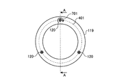
図4は、ズームレンズ装置100を示す正面図(その1)である。図4には、ズームレンズ装置100をl1レンズ105側から見た状態があらわされている。図4中符号401であらわされた仮想線は、ズームレンズ装置100の光軸を中心とする円をあらわしている。図4に示したように、調整ネジ120およびネジ穴121は、ズームレンズ装置100の光軸を中心とする同じ円周上に設けられている。
FIG. 4 is a front view (No. 1) showing the
図5は、図4におけるA−A断面図である。つぎに、図5を用いて、倒れ間隔調整板122の作用について説明する。図5には、ズームレンズ装置100のうち、l1レンズ105周辺の断面図があらわされている。図5に示したように、ズームレンズ装置100に組み込まれた倒れ間隔調整板122は、基部203が第2の鏡筒110に当接し、曲げ部204,205の先端部が固定レンズ保持枠119に当接した状態となっている。
5 is a cross-sectional view taken along line AA in FIG. Next, the operation of the fall
倒れ間隔調整板122を間にして対向する第2の鏡筒110と固定レンズ保持枠119との間隔は、倒れ間隔調整板122の板厚寸法よりも大きく設定されているので、ズームレンズ装置100を単純組み立てによって製造した場合にも、固定レンズ保持枠119に対して上述した付勢力を確実に作用させることができる。
Since the interval between the
これによって、ズームレンズ装置100は、ズームレンズ装置100を単純組み立てによって製造した場合にも、第2の鏡筒110に対する固定レンズ保持枠119のがたつきを抑えて、l1レンズ105およびL2レンズ104を安定して取り付けることができる。
Thus, even when the
図6は、ズームレンズ装置100の一部を示す断面図である。図6には、ズームレンズ装置100のうち、l1レンズ105周辺の断面図があらわされている。図6に示したように、ネジ穴121に対する調整ネジ120の螺合量を調整することによって、第2の鏡筒110に対する固定レンズ保持枠119の位置を調整することができる。なお、図6中紙面天地方向における天側の図は固定レンズ保持枠119の位置調整前、図6中紙面天地方向における地側は固定レンズ保持枠119の位置調整後の状態をあらわしている。
FIG. 6 is a cross-sectional view showing a part of the
調整ネジ120を緩める方向に回した場合、ネジ穴121に対する調整ネジ120の螺合量が減少して、固定レンズ保持枠119は、第2の鏡筒110から離反する方向へ移動する。具体的には、たとえば、固定レンズ保持枠119が、光軸方向において、図6中符号601によってあらわされる基準位置に位置づけられている場合に調整ネジ120を緩める方向に回すと、図6中符号602によってあらわされる移動位置まで移動する。
When the
図6から分かるように、固定レンズ保持枠119が、符号602によってあらわされる移動位置まで移動した場合にも、倒れ間隔調整板122は、固定レンズ保持枠119に対して上述した付勢力を確実に作用させることができる。
As can be seen from FIG. 6, even when the fixed
これによって、ズームレンズ装置100は、第2の鏡筒110に対する固定レンズ保持枠119の位置を調整した場合にも、第2の鏡筒110に対する固定レンズ保持枠119のがたつきを抑えて、l1レンズ105およびL2レンズ104を安定して取り付けることができる。
Thus, even when the position of the fixed
図7はズームレンズ装置100を示す正面図(その2)であり、図8は図7におけるA−A断面図である。また、図9はズームレンズ装置100を示す正面図(その3)であり、図10は図9におけるA−A断面図である。図7および図9には、ズームレンズ装置100をl1レンズ105側から見た状態があらわされている。図8および図10には、ズームレンズ装置100のうち、l1レンズ105周辺の断面図があらわされている。
FIG. 7 is a front view (No. 2) showing the
つぎに、図7〜図10を用いて、l1レンズ105およびL2レンズ104の光軸の調整方法について説明する。ズームレンズ装置100では、ネジ穴121に対する調整ネジ120の螺合量を調整することによって、l1レンズ105およびL2レンズ104の光軸の向きを調整する。
Next, a method for adjusting the optical axes of the
たとえば、図7中符号701であらわされる矢印の方向に調整ネジ120を回した場合、ネジ穴121に対する調整ネジ120の螺合量(噛み合い量)が増加して、第2の鏡筒110と固定レンズ保持枠119とが相対的に近付く。3箇所に設けられた調整ネジ120のうち、いずれか1つの調整ネジ120を締める方向に回した場合、固定レンズ保持枠119は、固定レンズ保持枠119において回されていない2つの調整ネジ120が挿入される2点を通る軸心回りに回動する。
For example, when the
これによって、図8中符号801であらわされるl1レンズ105およびL2レンズ104の光軸におけるl1レンズ105側が図7中紙面天地方向における天側へ移動し、光軸801におけるL2レンズ104側が図7中紙面天地方向における地側へ移動するように、光軸801の傾きを調整することができる。
As a result, the
また、たとえば、図9中符号901であらわされる矢印の方向に調整ネジ120を回した場合、ネジ穴121に対する調整ネジ120の螺合量(噛み合い量)が減少して、第2の鏡筒110と固定レンズ保持枠119とが相対的に離反する。3箇所に設けられた調整ネジ120のうち、いずれか1つの調整ネジ120を緩める方向に回した場合、固定レンズ保持枠119は、固定レンズ保持枠119において回されていない2つの調整ネジ120が挿入される2点を通る軸心回りに回動する。
Further, for example, when the
これによって、図10中符号1001であらわされるl1レンズ105およびL2レンズ104の光軸におけるl1レンズ105側が図9中紙面天地方向における地側へ移動し、光軸1001におけるL2レンズ104側が図9中紙面天地方向における天側へ移動するように、光軸1001の傾きを調整することができる。
As a result, the
実施の形態1のズームレンズ装置100では、光軸を中心とする同心円上に等間隔で3箇所に調整ネジ120が設けられているため、l1レンズ105およびL2レンズ104の光軸の傾きを、当該光軸周り全体に亘って調整することができる。また、光軸を中心とする同心円上に等間隔で設けられた調整ネジ120の個数を3個とすることで、l1レンズ105およびL2レンズ104の光軸の傾きを、当該光軸周り全体に亘って必要最低限の調整ネジ120の数で調整することができる。
In the
上述したように、実施の形態1のズームレンズ装置100によれば、固定レンズ保持枠119と第2の鏡筒110における取付面との間に倒れ間隔調整板122を位置づけた状態でネジ穴121に対して調整ネジ120を螺合することで、第2の鏡筒110に対する固定レンズ保持枠119のがたつきを抑え、l1レンズ105およびL2レンズ104を安定して取り付けることができる。
As described above, according to the
また、実施の形態1のズームレンズ装置100によれば、固定レンズ保持枠119と第2の鏡筒110における取付面との間に倒れ間隔調整板122を位置づけた状態でネジ穴121に対して調整ネジ120を螺合するだけで、第2の鏡筒110に対する固定レンズ保持枠119のがたつきを抑えることができるので、l1レンズ105およびL2レンズ104を安定して取り付けることができる。
Further, according to the
また、実施の形態1のズームレンズ装置100によれば、固定レンズ保持枠119と第2の鏡筒110との間に倒れ間隔調整板122を介在させている間は第2の鏡筒110に対する固定レンズ保持枠119のがたつきを抑えることができるので、第2の鏡筒110に固定レンズ保持枠119を取り付けたままで、l1レンズ105およびL2レンズ104の取付状態を容易に調整することができる。
Further, according to the
また、実施の形態1のズームレンズ装置100によれば、倒れ間隔調整板122に一体に設けられた曲げ部204,205によって第2の鏡筒110に対する固定レンズ保持枠119のがたつきを抑えることができるので、少ない部品数および少ない組み立て工程数で、l1レンズ105およびL2レンズ104を安定して取り付けることができる。
Further, according to the
また、実施の形態1のズームレンズ装置100によれば、倒れ間隔調整板122の製造に際して、プレスあるいは射出成型などの方法を用いて、曲げ部204,205を同時に製造することができるので、倒れ間隔調整板122を容易に製造することができる。
Further, according to the
また、実施の形態1のズームレンズ装置100によれば、ネジ穴121に対する調整ネジ120の螺合量に応じて光軸方向における固定レンズ保持枠119と第2の鏡筒110における取付面との距離を変化させることができるので、ズームレンズ装置100の組み立て後に第2の鏡筒110から固定レンズ保持枠119を取り外すことなく、l1レンズ105およびL2レンズ104の取付状態を容易に調整することができる。
Further, according to the
また、実施の形態1のズームレンズ装置100によれば、ネジ穴121に対する調整ネジ120の螺合量を取付位置ごとに調整することで固定レンズ保持枠119が保持するl1レンズ105およびL2レンズ104の光軸の向きを調整することができ、調整後には各螺合箇所ごとに付勢力を作用させることができるので、l1レンズ105およびL2レンズ104を安定して取り付けるとともに、l1レンズ105およびL2レンズ104の取付状態を容易かつ高精度に調整することができる。
Further, according to the
また、実施の形態1のズームレンズ装置100によれば、l1レンズ105およびL2レンズ104の光軸の向きを調整後には、隣り合う螺合箇所の中間に設けられた曲げ部205によって、隣り合う螺合箇所のそれぞれに対して均等に付勢力を作用させることができるので、l1レンズ105およびL2レンズ104を安定して取り付けるとともに、l1レンズ105およびL2レンズ104の取付状態を容易かつ高精度に調整することができる。
Further, according to the
また、実施の形態1のズームレンズ装置100によれば、螺合箇所を光軸周りの3箇所とすることで、螺合箇所の数を必要最小限とした上で、l1レンズ105およびL2レンズ104を安定して取り付けるとともに、l1レンズ105およびL2レンズ104の取付状態を容易かつ高精度に調整することができる。
In addition, according to the
なお、倒れ間隔調整板122の形状は、上述した実施の形態1で説明した形状に限るものではない。ズームレンズ装置100には、倒れ間隔調整板122に代えて、たとえば、倒れ間隔調整板122における曲げ部204,205の位置・形状・数あるいは開口部201の形状などを変更した別の倒れ間隔調整板が設けられていてもよい。
In addition, the shape of the fall
図11は、倒れ間隔調整板の変形例(その1)を示す斜視図である。つぎに、図11を用いて、倒れ間隔調整板の変形例(その1)について説明する。図11に示した倒れ間隔調整板1101は、上述した実施の形態1のズームレンズ装置100が備える倒れ間隔調整板122に代えて、固定レンズ保持枠119と第2の鏡筒110との間に設けられる。
FIG. 11 is a perspective view showing a modification (No. 1) of the fall interval adjusting plate. Next, a modified example (No. 1) of the fall interval adjusting plate will be described with reference to FIG. A tilt
図11に示したように、倒れ間隔調整板1101は、開口部201、凹部202、基部203、および位置決め穴206を備えている。倒れ間隔調整板1101は、曲げ部1102,1103を備えている。曲げ部1102,1103は、開口部201の中心側ほど固定レンズ保持枠119側に位置づけられるように屈曲した形状を有している。
As shown in FIG. 11, the fall
曲げ部1102は、開口部201の中心を中心とする同一円周上で、各凹部202の両隣となる位置にそれぞれ設けられており、大きさおよび固定レンズ保持枠119側への屈曲角度がすべて等しくなるように形成されている。
The
曲げ部1103は、開口部201の中心を中心とする同一の円周上に等間隔で点在する3箇所に設けられている。曲げ部1103は、開口部201の中心を中心とする同一の円周上で、各凹部202の中間となる位置に設けられている。曲げ部1103は、大きさおよび固定レンズ保持枠119側への屈曲角度がすべて等しくなるように形成されている。
The
ズームレンズ装置100においては、倒れ間隔調整板122に代えて倒れ間隔調整板1101を設けた場合にも、l1レンズ105およびL2レンズ104を安定して取り付けるとともに、l1レンズ105およびL2レンズ104の取付状態を容易かつ高精度に調整することができる。
In the
図12は、倒れ間隔調整板の変形例(その2)を示す斜視図である。つぎに、図12を用いて、倒れ間隔調整板の変形例(その2)について説明する。図12に示した倒れ間隔調整板1201は、上述した実施の形態1のズームレンズ装置100が備える倒れ間隔調整板122に代えて、固定レンズ保持枠119と第2の鏡筒110との間に設けられる。
FIG. 12 is a perspective view showing a modification (No. 2) of the fall interval adjusting plate. Next, a modified example (No. 2) of the fall interval adjusting plate will be described with reference to FIG. A tilt
図12に示したように、倒れ間隔調整板1201は、開口部201、凹部202、基部203、および位置決め穴206を備えている。倒れ間隔調整板1201における曲げ部1202は、接線方向を長手形状とする長尺状の部材であり、長手方向における中央部が固定レンズ保持枠119側に位置づけられるように湾曲している。曲げ部1202の大きさおよびおよび湾曲程度は、すべて等しくなるように形成されている。
As shown in FIG. 12, the fall
曲げ部1202は、開口部201の中心を中心とする同一円周上で、各凹部202の両隣となる位置にそれぞれ設けられている。曲げ部1202の長手方向における一端側は、基部203に固定されている。倒れ間隔調整板1201において、曲げ部1202の長手方向における他端側と、当該長手方向において基部203との間には、空間1203が形成されている。
The
倒れ間隔調整板1201がズームレンズ装置100に組み込まれた状態では、湾曲されることで固定レンズ保持枠119側に位置づけられた曲げ部1202の長手方向における中央部分が、固定レンズ保持枠119に当接した状態となっている。
In a state in which the tilt
長手方向において、曲げ部1202の他端側と基部203との間には空間1203が形成されているので、曲げ部1202が固定レンズ保持枠119に当接した状態から調整ネジ120を締める方向に回すと、曲げ部1202は他端側を空間1203内に移動させながら、湾曲を解消するように弾性変形する。
Since a
ズームレンズ装置100においては、倒れ間隔調整板122に代えて倒れ間隔調整板1201を設けた場合にも、l1レンズ105およびL2レンズ104を安定して取り付けるとともに、l1レンズ105およびL2レンズ104の取付状態を容易かつ高精度に調整することができる。
In the
また、倒れ間隔調整板122,1101,1201における曲げ部は、同一方向に屈曲しているものに限らない。たとえば、倒れ間隔調整板122における曲げ部204と曲げ部205との屈曲方向を、光軸方向において反対向きとしてもよい。同様に、たとえば、倒れ間隔調整板1101における曲げ部1102,1103の屈曲方向を、光軸方向において反対向きとしてもよい。
Moreover, the bending part in the fall space |
(実施の形態2)
図13は、実施の形態2のズームレンズ装置の一部を示す分解斜視図である。つぎに、図13を用いて、実施の形態2のズームレンズ装置の構成について説明する。なお、上述した実施の形態1と同一部分は同一符号であらわし、説明も省略する。図13に示したように、実施の形態2のズームレンズ装置は、上述した実施の形態1のズームレンズ装置100における第2の鏡筒110および固定レンズ保持枠119に代えて、第2の鏡筒1301を備えている。
(Embodiment 2)
FIG. 13 is an exploded perspective view illustrating a part of the zoom lens device according to the second embodiment. Next, the configuration of the zoom lens apparatus according to Embodiment 2 will be described with reference to FIG. The same parts as those in the first embodiment are denoted by the same reference numerals, and the description thereof is also omitted. As shown in FIG. 13, the zoom lens apparatus according to the second embodiment replaces the
第2の鏡筒1301は、上述したネジ穴121(縁部302を含む)や位置決めピン301に加えて、曲げ部1302が設けられている。曲げ部1302は、第2の鏡筒1301の軸心を中心とする同一円周上で、各縁部302の両隣となる位置にそれぞれ設けられている。
The
曲げ部1302は、第2の鏡筒1301の軸心方向に直交する面内に平行な切片部材1303と、切片部材1303において第2の鏡筒1301の軸心から離反する側の端部から固定レンズ保持枠119に突出する突起1304と、切片部材1303において第2の鏡筒1301の軸心側の端部を支持する脚部1305と、を備えている。脚部1305は、第2の鏡筒1301の軸心方向に平行に延出している。
The bending
実施の形態2のズームレンズ装置においては、ネジ穴121に調整ネジ120を螺合して、第2の鏡筒1301に固定レンズ保持枠119を取り付けると、突起1304が固定レンズ保持枠119に当接した状態となる。この状態から調整ネジ120を締める方向に回すと、曲げ部1302は、突起1304が第2の鏡筒1301側に移動するように切片部材1303を変位させる。このとき、脚部1305を湾曲させることで、突起1304が第2の鏡筒1301側に移動するように切片部材1303を変位させてもよい。
In the zoom lens device according to Embodiment 2, when the
上述したように、実施の形態2のズームレンズ装置によれば、第2の鏡筒1301に対して固定レンズ保持枠119を取り付けるだけで、第2の鏡筒1301に対する固定レンズ保持枠119のがたつきを抑えることができるので、l1レンズ105およびL2レンズ104を容易かつ安定して取り付けることができる。
As described above, according to the zoom lens device of the second embodiment, the fixed
また、実施の形態2のズームレンズ装置によれば、第2の鏡筒1301に対して固定レンズ保持枠119が取り付けられている間は第2の鏡筒1301に対する固定レンズ保持枠119のがたつきを抑えることができるので、第2の鏡筒1301に固定レンズ保持枠119を取り付けたままで、l1レンズ105およびL2レンズ104の取付状態を容易に調整することができる。
Further, according to the zoom lens device of the second embodiment, while the fixed
また、実施の形態2のズームレンズ装置によれば、ズームレンズ装置の組み立てに際しては、第2の鏡筒1301に対して固定レンズ保持枠119を取り付けるだけで第2の鏡筒1301に対する固定レンズ保持枠119のがたつきを抑えることができるので、少ない組み立て工程数でl1レンズ105およびL2レンズ104を安定して取り付けることができる。
Further, according to the zoom lens device of the second embodiment, when the zoom lens device is assembled, the fixed
また、実施の形態2のズームレンズ装置によれば、曲げ部1302が第2の鏡筒1301に一体に設けられているため、第2の鏡筒1301に対して固定レンズ保持枠119を取り付けるだけで、新たな部品および当該部品を組み込む作業をおこなうことなく、第2の鏡筒1301に対する固定レンズ保持枠119のがたつきを抑えることができるので、少ない部品点数および少ない組み立て工程数でl1レンズ105およびL2レンズ104を安定して取り付けることができる。
Further, according to the zoom lens device of Embodiment 2, since the bending
なお、実施の形態2においては、曲げ部1302が第2の鏡筒1301に設けられているズームレンズ装置について説明したが、これに限るものではない。図示を省略するが、曲げ部は、たとえば、固定レンズ保持枠119に設けられていてもよい。また、曲げ部は、たとえば、第2の鏡筒1301および固定レンズ保持枠119の両方に設けられていてもよい。
In the second embodiment, the zoom lens device in which the
(実施の形態3)
図14は、実施の形態3のズームレンズ装置を示す断面図である。つぎに、図14を用いて、実施の形態3のズームレンズ装置の構成について説明する。なお、上述した実施の形態1および2と同一部分は同一符号であらわし、説明も省略する。
(Embodiment 3)
FIG. 14 is a cross-sectional view illustrating the zoom lens device according to the third embodiment. Next, the configuration of the zoom lens apparatus according to Embodiment 3 will be described with reference to FIG. In addition, the same part as Embodiment 1 and 2 mentioned above is represented with the same code | symbol, and description is also abbreviate | omitted.
図14に示したように、実施の形態3のズームレンズ装置1400は、マウント108と第1の鏡筒109との間に設けられた、倒れ間隔調整板1401を備えている。マウント108と第1の鏡筒109とは、第1の鏡筒109に設けられた図示しない挿入口としてのネジ穴に、ピン状部材としてのFB調整ネジ1402を螺合させることによって連結されている。
As shown in FIG. 14, the
図示を省略するが、倒れ間隔調整板1401は、上述した実施の形態1で説明した倒れ間隔調整板122,1101および1201と同様に、マウント108および第1の鏡筒109に対して、マウント108と第1の鏡筒109とが離反する方向への付勢力を、光軸周りに均等に作用させるような曲げ部を備えている。
Although not shown, the fall
上述したように、実施の形態3のズームレンズ装置1400によれば、マウント108と第1の鏡筒109との間に倒れ間隔調整板1401を設けることで、ズームレンズ装置1400全体を安定してマウント108に取り付けるとともに、ズームレンズ装置1400全体の取付状態を調整することができる。
As described above, according to the
また、実施の形態3のズームレンズ装置100によれば、第2の鏡筒110と固定レンズ保持枠119との間、および、マウント108と第1の鏡筒109との間で光軸調整をおこなうことができるので、光軸の調整精度を一層高めることができる。
Further, according to the
なお、マウント108および第1の鏡筒109の少なくとも一方に、上述した曲げ部1302と同様の曲げ部(図示省略)を設け、倒れ間隔調整板1401を介することなく、マウント108に第1の鏡筒109を取り付けるようにしてもよい。
Note that at least one of the
以上のように、この発明にかかる光学部材支持機構、光学装置、および間隔調整部材は、1つの光軸上に配置される光学部材の支持に適しており、特に、組み立て後に光軸調整を要するズームレンズ装置などに適している。 As described above, the optical member supporting mechanism, the optical device, and the interval adjusting member according to the present invention are suitable for supporting the optical member disposed on one optical axis, and particularly require optical axis adjustment after assembly. Suitable for zoom lens devices.
100 ズームレンズ装置
101 L5レンズ
102 L4レンズ
103 L3レンズ
104 L2レンズ
105 l1レンズ
110 第2の鏡筒
119 固定レンズ保持枠
120 調整ネジ
121 ネジ穴
122 倒れ間隔調整板
1101 倒れ間隔調整板
1102,1103 曲げ部
1201 倒れ間隔調整板
1202 曲げ部
1301 第2の鏡筒
1302 曲げ部
1400 ズームレンズ装置
1402 FB調整ネジ
DESCRIPTION OF
Claims (11)
前記光軸方向において前記保持部材に対向する取付面を有する支持部材と、
前記保持部材を前記支持部材に取り付ける取付手段と、
前記取付手段によって取り付けられる前記保持部材と前記支持部材との間に設けられる間隔調整部材と、
を備え、
前記間隔調整部材は、前記保持部材および前記支持部材に対して、前記保持部材と前記支持部材とが相対的に離反する方向への付勢力を作用させることを特徴とする光学部材支持機構。 A holding member for holding an arbitrary optical member among a plurality of optical members arranged on the optical axis;
A support member having an attachment surface facing the holding member in the optical axis direction;
Attachment means for attaching the holding member to the support member;
An interval adjusting member provided between the holding member and the support member attached by the attaching means;
With
The distance adjusting member applies an urging force in a direction in which the holding member and the support member are relatively separated from each other to the holding member and the support member.
前記曲げ部は、前記各取付位置の近傍に設けられていることを特徴とする請求項3に記載の光学部材支持機構。 There are a plurality of the attachment positions around the optical axis,
The optical member support mechanism according to claim 3, wherein the bent portion is provided in the vicinity of each of the attachment positions.
前記曲げ部は、前記取付位置のうち前記光軸周りに隣り合う取付位置の中間に設けられていることを特徴とする請求項3に記載の光学部材支持機構。 There are a plurality of the attachment positions around the optical axis,
The optical member support mechanism according to claim 3, wherein the bent portion is provided at an intermediate position between the mounting positions adjacent to each other around the optical axis.
前記光軸方向において前記保持部材に対向する取付面を有する支持部材と、
前記保持部材を前記支持部材に取り付ける取付手段と、
を備え、
前記保持部材および前記支持部材の少なくとも一方は、前記支持部材および前記保持部材の少なくとも一方に対して、前記保持部材と前記支持部材とが相対的に離反する方向への付勢力を作用させることを特徴とする光学部材支持機構。 A holding member for holding an arbitrary optical member among a plurality of optical members arranged on the optical axis;
A support member having an attachment surface facing the holding member in the optical axis direction;
Attachment means for attaching the holding member to the support member;
With
At least one of the holding member and the support member applies an urging force in a direction in which the holding member and the support member are relatively separated from each other to at least one of the support member and the holding member. An optical member support mechanism.
前記間隔調整部材の一部を前記保持部材側および前記取付面の少なくとも一方側へ屈曲させた曲げ部を備え、当該曲げ部の弾性によって、前記支持部材および前記保持部材に対して、前記保持部材と前記支持部材とが相対的に離反する方向への付勢力を作用させることを特徴とする間隔調整部材。
Spacing adjustment provided between a holding member that holds an arbitrary optical member among a plurality of optical members arranged on the optical axis, and a support member that has a mounting surface that faces the holding member in the optical axis direction. A member,
A bending portion formed by bending a part of the gap adjusting member toward at least one of the holding member side and the mounting surface, and the holding member with respect to the supporting member and the holding member by elasticity of the bending portion; An interval adjusting member, wherein a biasing force is applied in a direction in which the support member and the support member are relatively separated from each other.
Priority Applications (2)
| Application Number | Priority Date | Filing Date | Title |
|---|---|---|---|
| JP2006152374A JP2007322709A (en) | 2006-05-31 | 2006-05-31 | Optical member support mechanism, optical device, and interval adjustment member |
| US11/518,203 US20070280625A1 (en) | 2006-05-31 | 2006-09-11 | Optical member support mechanism, optical device, and gap adjusting member |
Applications Claiming Priority (1)
| Application Number | Priority Date | Filing Date | Title |
|---|---|---|---|
| JP2006152374A JP2007322709A (en) | 2006-05-31 | 2006-05-31 | Optical member support mechanism, optical device, and interval adjustment member |
Publications (2)
| Publication Number | Publication Date |
|---|---|
| JP2007322709A true JP2007322709A (en) | 2007-12-13 |
| JP2007322709A5 JP2007322709A5 (en) | 2009-06-18 |
Family
ID=38790293
Family Applications (1)
| Application Number | Title | Priority Date | Filing Date |
|---|---|---|---|
| JP2006152374A Pending JP2007322709A (en) | 2006-05-31 | 2006-05-31 | Optical member support mechanism, optical device, and interval adjustment member |
Country Status (2)
| Country | Link |
|---|---|
| US (1) | US20070280625A1 (en) |
| JP (1) | JP2007322709A (en) |
Cited By (4)
| Publication number | Priority date | Publication date | Assignee | Title |
|---|---|---|---|---|
| JP2010107735A (en) * | 2008-10-30 | 2010-05-13 | Canon Inc | Support device for optical element, exposure device using the same, and method for manufacturing device |
| JP4496299B1 (en) * | 2010-02-24 | 2010-07-07 | シャープ株式会社 | Lens body, light source unit, and illumination device |
| JP2011158873A (en) * | 2010-01-06 | 2011-08-18 | Panasonic Corp | Lens barrel and imaging device |
| JP2014089362A (en) * | 2012-10-31 | 2014-05-15 | Canon Inc | Lens device |
Families Citing this family (4)
| Publication number | Priority date | Publication date | Assignee | Title |
|---|---|---|---|---|
| DE102009056659B4 (en) * | 2009-12-02 | 2018-05-17 | Conti Temic Microelectronic Gmbh | Lens for a semiconductor camera and method for focusing a semiconductor camera |
| JP5882715B2 (en) * | 2011-12-16 | 2016-03-09 | キヤノン株式会社 | Lens barrel capable of adjusting lens and imaging apparatus including the same |
| CN102540401A (en) * | 2011-12-31 | 2012-07-04 | 武汉金运激光股份有限公司 | Lens adjusting device |
| CN111522116A (en) * | 2020-06-01 | 2020-08-11 | 广东奥普特科技股份有限公司 | Adjusting mechanism of fixed-focus lens |
Citations (11)
| Publication number | Priority date | Publication date | Assignee | Title |
|---|---|---|---|---|
| JPH037919A (en) * | 1989-06-05 | 1991-01-16 | Nitto Kogaku Kk | Back focus adjusting device for vari-focal lens system |
| JPH05127059A (en) * | 1991-10-30 | 1993-05-25 | Asahi Optical Co Ltd | Device for adjusting focus of variable focal distance lens for camera |
| JPH0821939A (en) * | 1994-07-06 | 1996-01-23 | Asahi Optical Co Ltd | Device for adjusting lens position in optical axis direction |
| JPH10293238A (en) * | 1997-04-17 | 1998-11-04 | Nikon Corp | Lens barrel provided with impulse absorbing mechanism |
| JPH11337798A (en) * | 1998-05-27 | 1999-12-10 | Fuji Photo Film Co Ltd | Film unit with lens |
| JP2000352648A (en) * | 1999-06-09 | 2000-12-19 | Fuji Photo Film Co Ltd | Method for adjusting eccentricity of lens and lens device |
| JP2002156575A (en) * | 2000-11-17 | 2002-05-31 | Asahi Optical Co Ltd | Fpc base plate holding structure for zoom lens barrel |
| JP2003043328A (en) * | 2001-07-30 | 2003-02-13 | Sony Corp | Zoom lens adjusting method, imaging device adjusting method, zoom lens and the imaging device |
| JP2003202485A (en) * | 2002-01-08 | 2003-07-18 | Chinontec Kk | Zoom lens barrel and camera apparatus |
| JP2004031491A (en) * | 2002-06-24 | 2004-01-29 | Nikon Corp | Optical element retaining mechanism, optical system lens-barrel and aligner |
| JP2005292466A (en) * | 2004-03-31 | 2005-10-20 | Canon Inc | Optical element holding mechanism, lens unit and optical apparatus |
Family Cites Families (2)
| Publication number | Priority date | Publication date | Assignee | Title |
|---|---|---|---|---|
| US6556363B2 (en) * | 2001-07-16 | 2003-04-29 | Wen-Wen Chiu | Lens module |
| JP3809826B2 (en) * | 2003-05-19 | 2006-08-16 | ソニー株式会社 | Lens driving mechanism and imaging apparatus |
-
2006
- 2006-05-31 JP JP2006152374A patent/JP2007322709A/en active Pending
- 2006-09-11 US US11/518,203 patent/US20070280625A1/en not_active Abandoned
Patent Citations (11)
| Publication number | Priority date | Publication date | Assignee | Title |
|---|---|---|---|---|
| JPH037919A (en) * | 1989-06-05 | 1991-01-16 | Nitto Kogaku Kk | Back focus adjusting device for vari-focal lens system |
| JPH05127059A (en) * | 1991-10-30 | 1993-05-25 | Asahi Optical Co Ltd | Device for adjusting focus of variable focal distance lens for camera |
| JPH0821939A (en) * | 1994-07-06 | 1996-01-23 | Asahi Optical Co Ltd | Device for adjusting lens position in optical axis direction |
| JPH10293238A (en) * | 1997-04-17 | 1998-11-04 | Nikon Corp | Lens barrel provided with impulse absorbing mechanism |
| JPH11337798A (en) * | 1998-05-27 | 1999-12-10 | Fuji Photo Film Co Ltd | Film unit with lens |
| JP2000352648A (en) * | 1999-06-09 | 2000-12-19 | Fuji Photo Film Co Ltd | Method for adjusting eccentricity of lens and lens device |
| JP2002156575A (en) * | 2000-11-17 | 2002-05-31 | Asahi Optical Co Ltd | Fpc base plate holding structure for zoom lens barrel |
| JP2003043328A (en) * | 2001-07-30 | 2003-02-13 | Sony Corp | Zoom lens adjusting method, imaging device adjusting method, zoom lens and the imaging device |
| JP2003202485A (en) * | 2002-01-08 | 2003-07-18 | Chinontec Kk | Zoom lens barrel and camera apparatus |
| JP2004031491A (en) * | 2002-06-24 | 2004-01-29 | Nikon Corp | Optical element retaining mechanism, optical system lens-barrel and aligner |
| JP2005292466A (en) * | 2004-03-31 | 2005-10-20 | Canon Inc | Optical element holding mechanism, lens unit and optical apparatus |
Cited By (6)
| Publication number | Priority date | Publication date | Assignee | Title |
|---|---|---|---|---|
| JP2010107735A (en) * | 2008-10-30 | 2010-05-13 | Canon Inc | Support device for optical element, exposure device using the same, and method for manufacturing device |
| JP2011158873A (en) * | 2010-01-06 | 2011-08-18 | Panasonic Corp | Lens barrel and imaging device |
| JP4496299B1 (en) * | 2010-02-24 | 2010-07-07 | シャープ株式会社 | Lens body, light source unit, and illumination device |
| JP2010165683A (en) * | 2010-02-24 | 2010-07-29 | Sharp Corp | Lens body, light source unit, and illuminating device |
| JP2014089362A (en) * | 2012-10-31 | 2014-05-15 | Canon Inc | Lens device |
| US9124790B2 (en) | 2012-10-31 | 2015-09-01 | Canon Kabushiki Kaisha | Lens apparatus and image pickup apparatus |
Also Published As
| Publication number | Publication date |
|---|---|
| US20070280625A1 (en) | 2007-12-06 |
Similar Documents
| Publication | Publication Date | Title |
|---|---|---|
| JP2007322709A (en) | Optical member support mechanism, optical device, and interval adjustment member | |
| JP2007322709A5 (en) | ||
| JP6382066B2 (en) | Imaging device | |
| JP5109232B2 (en) | Lens barrel | |
| JP2008139442A (en) | Mirror attachment structure | |
| JP2013238760A (en) | Optical device having eccentricity/tilt adjustment structure | |
| US20020118468A1 (en) | Lens barrel for use in zoom lens apparatus | |
| KR101828408B1 (en) | Adjusting apparatus for optical element | |
| JP2011095324A (en) | Lens device | |
| US11064120B2 (en) | Imaging-element inclination adjustment mechanism, method for adjusting inclination of imaging element, and imaging apparatus | |
| JPH10301013A (en) | Lens driving mechanism | |
| JP2009156960A (en) | Lens barrel | |
| JP2006072059A (en) | Eccentricity adjusting apparatus for lens barrel | |
| JP5336919B2 (en) | Lens barrel | |
| US9829675B2 (en) | Lens barrel | |
| WO2018135453A1 (en) | Imaging device | |
| US20230408789A1 (en) | Lens barrel | |
| JP7380000B2 (en) | Lens barrel and lens barrel alignment method | |
| WO2011158643A1 (en) | Focal-point correction device | |
| JP2020008707A (en) | Lens barrel | |
| JP3792875B2 (en) | Optical element holding device and optical apparatus using the same | |
| JP2011002729A (en) | Guide mechanism, camera module, and method for positioning optical system | |
| JP2003222924A (en) | Camera | |
| JP2003279823A (en) | Tilt aligning mechanism | |
| WO2018135454A1 (en) | Imaging device |
Legal Events
| Date | Code | Title | Description |
|---|---|---|---|
| A521 | Written amendment |
Free format text: JAPANESE INTERMEDIATE CODE: A523 Effective date: 20090424 |
|
| A621 | Written request for application examination |
Free format text: JAPANESE INTERMEDIATE CODE: A621 Effective date: 20090424 |
|
| A131 | Notification of reasons for refusal |
Free format text: JAPANESE INTERMEDIATE CODE: A131 Effective date: 20110215 |
|
| A521 | Written amendment |
Free format text: JAPANESE INTERMEDIATE CODE: A523 Effective date: 20110418 |
|
| A131 | Notification of reasons for refusal |
Free format text: JAPANESE INTERMEDIATE CODE: A131 Effective date: 20110816 |
|
| A02 | Decision of refusal |
Free format text: JAPANESE INTERMEDIATE CODE: A02 Effective date: 20111220 |