EP3454457A1 - Elektromotor mit mindestens einem kühlmittelkanal - Google Patents
Elektromotor mit mindestens einem kühlmittelkanal Download PDFInfo
- Publication number
- EP3454457A1 EP3454457A1 EP18178552.8A EP18178552A EP3454457A1 EP 3454457 A1 EP3454457 A1 EP 3454457A1 EP 18178552 A EP18178552 A EP 18178552A EP 3454457 A1 EP3454457 A1 EP 3454457A1
- Authority
- EP
- European Patent Office
- Prior art keywords
- stator
- housing
- electric motor
- motor according
- coolant
- Prior art date
- Legal status (The legal status is an assumption and is not a legal conclusion. Google has not performed a legal analysis and makes no representation as to the accuracy of the status listed.)
- Granted
Links
Images
Classifications
-
- H—ELECTRICITY
- H02—GENERATION; CONVERSION OR DISTRIBUTION OF ELECTRIC POWER
- H02K—DYNAMO-ELECTRIC MACHINES
- H02K1/00—Details of the magnetic circuit
- H02K1/06—Details of the magnetic circuit characterised by the shape, form or construction
- H02K1/12—Stationary parts of the magnetic circuit
- H02K1/18—Means for mounting or fastening magnetic stationary parts on to, or to, the stator structures
-
- H—ELECTRICITY
- H02—GENERATION; CONVERSION OR DISTRIBUTION OF ELECTRIC POWER
- H02K—DYNAMO-ELECTRIC MACHINES
- H02K1/00—Details of the magnetic circuit
- H02K1/06—Details of the magnetic circuit characterised by the shape, form or construction
- H02K1/12—Stationary parts of the magnetic circuit
- H02K1/20—Stationary parts of the magnetic circuit with channels or ducts for flow of cooling medium
-
- H—ELECTRICITY
- H02—GENERATION; CONVERSION OR DISTRIBUTION OF ELECTRIC POWER
- H02K—DYNAMO-ELECTRIC MACHINES
- H02K5/00—Casings; Enclosures; Supports
- H02K5/04—Casings or enclosures characterised by the shape, form or construction thereof
- H02K5/20—Casings or enclosures characterised by the shape, form or construction thereof with channels or ducts for flow of cooling medium
-
- H—ELECTRICITY
- H02—GENERATION; CONVERSION OR DISTRIBUTION OF ELECTRIC POWER
- H02K—DYNAMO-ELECTRIC MACHINES
- H02K5/00—Casings; Enclosures; Supports
- H02K5/04—Casings or enclosures characterised by the shape, form or construction thereof
- H02K5/20—Casings or enclosures characterised by the shape, form or construction thereof with channels or ducts for flow of cooling medium
- H02K5/203—Casings or enclosures characterised by the shape, form or construction thereof with channels or ducts for flow of cooling medium specially adapted for liquids, e.g. cooling jackets
-
- H—ELECTRICITY
- H02—GENERATION; CONVERSION OR DISTRIBUTION OF ELECTRIC POWER
- H02K—DYNAMO-ELECTRIC MACHINES
- H02K9/00—Arrangements for cooling or ventilating
- H02K9/08—Arrangements for cooling or ventilating by gaseous cooling medium circulating wholly within the machine casing
-
- H—ELECTRICITY
- H02—GENERATION; CONVERSION OR DISTRIBUTION OF ELECTRIC POWER
- H02K—DYNAMO-ELECTRIC MACHINES
- H02K9/00—Arrangements for cooling or ventilating
- H02K9/19—Arrangements for cooling or ventilating for machines with closed casing and closed-circuit cooling using a liquid cooling medium, e.g. oil
- H02K9/197—Arrangements for cooling or ventilating for machines with closed casing and closed-circuit cooling using a liquid cooling medium, e.g. oil in which the rotor or stator space is fluid-tight, e.g. to provide for different cooling media for rotor and stator
-
- H—ELECTRICITY
- H02—GENERATION; CONVERSION OR DISTRIBUTION OF ELECTRIC POWER
- H02K—DYNAMO-ELECTRIC MACHINES
- H02K5/00—Casings; Enclosures; Supports
- H02K5/04—Casings or enclosures characterised by the shape, form or construction thereof
Definitions
- the present invention relates to an electric motor, in particular an internal rotor motor with a stator constructed of lamellae and with a rotor arranged concentrically in the stator, with a housing enclosing the stator circumferentially and with two housing caps for axially closing the housing on both sides and for receiving and guiding a shaft of the Rotor, wherein the lamellae each have at least three circumferentially arranged webs for forming at least one coolant channel between the stator and the housing and wherein the at least one coolant channel is fluid-tight limited by the housing caps.
- the stator In electric motors with a fixed stator, the stator consists of punched disks or lamellae, in the inner region of which recesses for windings are arranged.
- the outdoor area is cylindrically shaped.
- the lamellae are stacked axially on top of each other, creating a cylindrical body.
- the waste heat of the electric motor is usually dissipated via the fins and the housing.
- the housing usually has one or more channels through which a cooling liquid is passed.
- two-part solutions are available in which an additional cooling jacket forms the cooling channel together with the housing. The coolant flows through the sealed channel and does not come into contact with the stator.
- cooling liquid is spatially separated from the heat source by the stator through walls of the housing or the integrated cooling channels. This spatial separation is necessary in particular due to the electrical conductivity of the cooling liquid and due to the lack of sealing of the stator relative to the rotor.
- DE 11 2014 001 277 T5 discloses a microchannel heat exchanger integrated in a stator core.
- the stator core is constructed of stacked sheets having different geometries at their outer diameter, which form cooling channels through which a coolant flows.
- the stator core consists of stacked sheets and comprises on its outer diameter structures that form cooling channels, which are traversed by a coolant.
- DE 10 2014 220 510 A1 discloses a disc pack of a rotor or stator for an electric machine and a method of manufacturing the same.
- the stator is made of stacked sheets, which have openings through which cooling channels are formed and which are flowed through by a coolant.
- the invention has for its object to provide an electric motor with a stator cooling, in which the coolant is reliably separated by simple technical means of current-carrying components of the electric motor.
- An object of the present invention is an electric motor, in particular an internal rotor motor, with a stator constructed from a multiplicity of axially aligned lamellae, the stator being in Direction of a stator arranged concentrically arranged in the stator stator teeth for receiving stator windings.
- the electric motor has a stator enclosing the stator radially and two housing caps for axially closing the housing on both sides and for receiving and guiding a shaft of the rotor.
- the lamellae each have at least three circumferentially arranged webs for forming at least one coolant channel between the stator and the housing, wherein the at least one coolant channel can be limited fluid-tight by the housing caps.
- the inventive design of the electric motor can be formed between the housing or alternatively a tube which serves as a housing, and the stator at least one coolant channel.
- the housing may also be rectangular, round, oval and the like.
- the coolant or the coolant can flow directly between the stator and the housing.
- the coolant channel is formed radially by the stator and the housing.
- the fins and the housing are easy to manufacture.
- the lamellae can have circumferentially formed, radially outwardly extending webs.
- circumferential recesses for forming the webs and arranged between the webs and the housing coolant channels can be introduced into existing slats. It can thus be created by minor structural measures on the vane geometry coolant channels, with most other components of the electric motor can remain unchanged.
- the coolant passes through the coolant channel adjacent to the fins and is in direct contact with the stator. This allows the Heat transfer to be optimized. By fluid-tight completion of the stator to the housing caps prevents coolant can reach the rotor, whereby a safe separation of the coolant is given to the windings of the stator.
- the stator has two spacer rings, each with at least one circumferentially arranged web, wherein the lamellae of the stator are arranged between the two spacer rings.
- the at least one spacer ring has at least one web for forming or continuing the coolant channel formed by the lamellae.
- the at least one spacer ring has the same diameter as the lamellae.
- At least two spacer rings can be arranged in the housing and be part of the stator.
- the at least one spacer serves as an axial extension of the fins and the at least one coolant channel.
- the webs of the spacer ring are modeled on the webs of the slats and can extend them axially.
- the two spacer rings are arranged axially rotated with respect to each other.
- a spacer ring is positioned outside, while the lamellae are arranged between the two spacer rings.
- the orientation of the slats can be done after a spacer ring.
- the second spacer ring is arranged axially rotated. This results in the cooling channel, which can be guided circumferentially meandering over the entire outer surface of the stator. As a result, only one inlet and only one outlet is necessary.
- the entire stator can be cooled along the outer surface.
- the spacers and the housing cover serve as axial deflection of the coolant channel.
- the at least one web of the at least one lamella has at least one groove for receiving a sealant.
- a web head is arranged at least one web without a sealant or is approximately free of the sealant, since the support torque can be transmitted from the electric motor here in the housing. But so that no coolant can penetrate through the web heads in the stator, the webs of the axially juxtaposed slats on the longitudinal side a sealing edge or a groove for receiving a sealant.
- suitable recesses may be positioned on the webs.
- the at least one coolant channel can be sealed axially relative to the housing, so that a coolant exchange over the webs can be prevented. As a result, a coolant flow can be controlled by the stator.
- At least one circumferentially arranged web of at least one spacer ring has a groove corresponding to the at least one lamella for receiving a sealant.
- the sealant can thus be applied beyond the lamellae on the webs of the spacer rings, so that the entire coolant channel can be made radially fluid-tight.
- the stator is designed so that it can be inserted into a two-part tool.
- the Entformungscardi is axial. This tool can be, for example, a vulcanization tool.
- a sealant is applied in the outer region of the stator and seals the coolant channel from a Statorinnen Symposium Silver.
- At least one spacer ring has at least one axially arranged groove for receiving a sealant on.
- the two spacers have front side recesses or grooves in the region of the spacer ring side coolant channel bottom. When applying the sealant, these recesses can fill with the sealant and form an axial seal to the interior or to the rotor. In the area of the webs on the outer diameter, the axial sealing lips continue on the end faces of the webs of the spacer rings.
- At least one coolant channel is at least partially coated with the sealant.
- the coating can be pressed between the webs of the stator and the webs of the spacers and the housing and thus be performed completely fluid-tight. As a result, the risk of leakage or ingress of the coolant to the windings, for example due to age-related soot formation between the slats, can be prevented.
- a coating with the sealant may be a final processing step of the stator, whereby a subsequent painting or preserving the stator can be omitted.
- the at least one spacer ring is formed axially as a sealing means.
- the spacer ring may alternatively or additionally be formed from an elastic plastic or silicone, so that the spacer ring between the housing cap and stator can be compressed and at the same time serve as an axial seal. As a result, additional sealant can be omitted.
- the stator has at least one sealing lamella for circumferentially receiving the sealing means, at least between a first and a second lamella and between a last and a penultimate lamella.
- the sealing blade has a groove corresponding to the grooves of the webs of the lamellae radial expansion.
- the sealing strips and the lamellae can be installed alternately.
- the circumferential seal grooves fill.
- the outer area or the web heads of the lamellae remain sealant-free and can thus transfer the mechanical forces to the housing.
- the housing and / or at least one housing cap on at least one coolant inlet and at least one coolant outlet.
- the coolant can be guided into the coolant channel in a controlled manner for cooling the stator and led out.
- the coolant is led out only when the cooling liquid has been guided around the entire lateral surface of the stator.
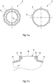
- FIG. 1a shows a top view of a blade 1 of the stator 2 and a spacer ring 4 of the stator 2 in an embodiment of the invention.
- the lamella 1 and the spacer ring 4 have circumferentially arranged webs 6.
- the webs 6 space the lamellae 1 and the spacer rings 4 with respect to a housing and thus form coolant channels 8.
- the lamellae 1 have stator teeth 10 which are directed into an interior area for receiving stator windings.
- FIG. 1b illustrated in a detailed view of a web 6 a blade 1 in an embodiment of the invention.
- a groove 12 arranged on flanks of the web 6 for receiving a sealant 14 is shown.
- the sealing means 14 is distributed over the coolant channel 8 across the surface or serves as a coating for the coolant channel 8.
- a web head 16 is free of a sealing means 14, so that mechanical forces of the stator 2 can be transmitted through the web head 16.
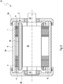
- FIG. 2 shows in a cross section an electric motor 18 according to the invention according to one embodiment.
- the electric motor 18 has a rotor 20 arranged in the interior region of the stator 2 with a shaft 22.
- the stator 2 is arranged in a tubular housing 24.
- the stator 2 consists here of a plurality of fins 1 and two axially spaced fins 1 spacer rings 4.
- the stator 2 has arranged in the region of the rotor 20 axially extending stator windings 26.
- the housing 24 is closed axially on both sides by a respective housing cap 28.
- the housing caps 28 have unnumbered bearings for receiving and guiding the shaft 22 of the rotor 20.
- the coolant channels 8 are formed between the housing 24 and the stator 2.
- the coolant channels 8 are sealed axially by the housing caps 28 relative to the rotor 20 and the stator windings 26.
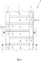
- FIG. 3 shows a schematic representation of a section of a circumferential development of the stator 2 according to the invention.
- the course of the coolant channel 8 along the stator 2 is illustrated.
- the spacers 4 are arranged axially rotated relative to each other, so that the webs 6 allow a meandering course of the coolant channel 8 circumferentially along the stator 2.
- the axially arranged housing caps 28 serve as axial boundaries of the coolant channel 8.
- the thick arrows illustrate a coolant inlet into the coolant channel 8 (right arrow) and a coolant outlet from the coolant channel 8 also (left arrow).
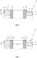
- FIG. 4 shows a sectional view of a stator 2 according to the invention along the section line AA FIG. 3 according to one embodiment.
- the FIG. 4 illustrates in particular the arrangement of the sealant 14 in the region of the spacers 4.
- the spacers 4 have frontally introduced recesses 30 for receiving the sealant 14.
- the Housing caps 28 can be connected to the axially arranged sealing means 14 and close the coolant channel 8 axially fluid-tight.
- FIG. 5 shows a sectional view of a stator 2 according to the invention along the section line AA FIG. 3 according to a further embodiment.
- the stator 2 has sealing lamellae 32 in addition to the lamellae 1.
- the sealing lamellae 32 have a smaller radius than the lamellae 1 and can when filling the groove 12 from FIG. 1b radially also filled with the sealant 14.
- a groove for receiving the sealant 14 is formed by arranging a sealing lamella 32 between two lamellae 1.
Landscapes
- Engineering & Computer Science (AREA)
- Power Engineering (AREA)
- Motor Or Generator Cooling System (AREA)
- Motor Or Generator Frames (AREA)
- Iron Core Of Rotating Electric Machines (AREA)
Abstract
Description
- Die vorliegende Erfindung betrifft einen Elektromotor, insbesondere einen Innenläufermotor mit einem aus Lamellen aufgebauten Stator und mit einem konzentrisch im Stator angeordneten Rotor, mit einem den Stator umfangsseitig umschließenden Gehäuse und mit zwei Gehäusekappen zum axial beidseitigen Verschließen des Gehäuses und zum Aufnehmen und Führen einer Welle des Rotors, wobei die Lamellen jeweils mindestens drei umfangsseitig angeordnete Stege zum Ausbilden von mindestens einem Kühlmittelkanal zwischen dem Stator und dem Gehäuse aufweisen und wobei der mindestens eine Kühlmittelkanal durch die Gehäusekappen fluiddicht begrenzbar ist.
- Bei Elektromotoren mit feststehendem Stator besteht der Stator aus gestanzten Scheiben bzw. Lamellen, in deren innerem Bereich Aussparungen für Wicklungen angeordnet sind. Der Außenbereich ist dabei zylindrisch geformt. Die Lamellen werden axial aufeinander gestapelt, so dass ein zylindrischer Körper entsteht. Durch eine Wärmebehandlung verkleben die Scheiben und es entsteht eine fest verbundene Einheit. Die Abwärme des Elektromotors wird in der Regel über die Lamellen und das Gehäuse abgeführt. Dazu verfügt das Gehäuse meist über einen oder mehrere Kanäle, durch die eine Kühlflüssigkeit geleitet wird. Alternativ sind auch zweiteilige Lösungen verfügbar, bei denen ein zusätzlicher Kühlmantel zusammen mit dem Gehäuse den Kühlkanal bildet. Die Kühlflüssigkeit fließt durch den abgedichteten Kanal und kommt mit dem Stator nicht in Kontakt.
- Derartige Gehäuse mit integrierten Kühlkanälen sind jedoch aufwendig in der Herstellung und kostenintensiv. Durch den Einsatz eines zusätzlichen Kühlmantels kann die Herstellung der Teile vereinfacht werden, jedoch muss hierfür ein zusätzliches Bauteil auf dem Gehäuse angebracht werden. In beiden Fällen ist die Kühlflüssigkeit allerdings vom Stator durch Wände des Gehäuses bzw. der integrierten Kühlkanäle räumlich von der Wärmequelle getrennt. Diese räumliche Trennung ist insbesondere aufgrund der elektrischen Leitfähigkeit der Kühlflüssigkeit und aufgrund der mangelnden Abdichtung des Stators gegenüber dem Rotor notwendig.
-
DE 11 2014 001 277 T5 offenbart einen in einem Statorkern integrierten Mikrokanalwärmetauscher. Der Statorkern ist aus gestapelten Blechen aufgebaut, die an ihrem Außendurchmesser unterschiedliche Geometrien aufweisen, welche Kühlkanäle formen, durch die ein Kühlmittel fließt. -
DE 10 2014 219 724 A1 offenbart eine elektrische Maschine mit einer Kühlung. Der Statorkern besteht dabei aus gestapelten Blechen und umfasst auf seinem Außendurchmesser Strukturen, welche Kühlkanäle formen, die von einem Kühlmittel durchflossen werden. -
DE 10 2014 220 510 A1 offenbart ein Lamellenpaket eines Rotors oder Stators für eine elektrische Maschine sowie ein Verfahren zum Fertigen desselben. Das Statorpaket besteht aus gestapelten Blechen, welche Durchbrüche aufweisen, durch die Kühlkanäle geformt werden und die mit einem Kühlmittel durchströmt werden. - Der Erfindung liegt die Aufgabe zugrunde, einen Elektromotor mit einer Statorkühlung zu schaffen, bei dem das Kühlmittel mit einfachen technischen Mitteln von stromführenden Komponenten des Elektromotors zuverlässig getrennt ist.
- Ein Gegenstand der vorliegenden Erfindung ist ein Elektromotor, insbesondere ein Innenläufermotor, mit einem aus einer Vielzahl an axial aneinandergereihten Lamellen aufgebauten Stator, wobei der Stator in Richtung eines im Stator konzentrisch angeordneten Rotors angeordnete Statorzähne zum Aufnehmen von Statorwicklungen aufweist. Der Elektromotor weist ein den Stator radial umschließendes Gehäuse und zwei Gehäusekappen zum axial beidseitigen Verschließen des Gehäuses und zum Aufnehmen und Führen einer Welle des Rotors auf. Erfindungsgemäß weisen die Lamellen jeweils mindestens drei umfangsseitig angeordnete Stege zum Ausbilden von mindestens einem Kühlmittelkanal zwischen dem Stator und dem Gehäuse auf, wobei der mindestens eine Kühlmittelkanal durch die Gehäusekappen fluiddicht begrenzbar ist.
- Durch die erfindungsgemäße Ausführung des Elektromotors kann zwischen dem Gehäuse oder alternativ einem Rohr, welches als Gehäuse dient, und dem Stator mindestens ein Kühlmittelkanal gebildet werden. Abhängig von einer Ausbildung des Stators kann das Gehäuse zudem rechteckig, rund, oval und dergleichen ausgebildet sein. Die Kühlflüssigkeit bzw. das Kühlmittel kann direkt zwischen Stator und Gehäuse entlangfließen. Der Kühlmittelkanal wird radial durch den Stator und das Gehäuse gebildet. Dadurch kann eine sehr kompakte Konstruktion des mindestens einen Kühlmittelkanals und auch des Elektromotors erreicht werden. Die Lamellen und das Gehäuse sind einfach herzustellen. Insbesondere können die Lamellen umfangsseitig ausgebildete, sich radial nach außen erstreckende Stege aufweisen. Hierfür können in bereits bestehende Lamellen umfangsseitige Aussparungen zum Bilden der Stege und der zwischen den Stegen und dem Gehäuse angeordneten Kühlmittelkanäle eingebracht werden. Es können somit durch geringfügige konstruktive Maßnahmen an der Lamellengeometrie Kühlmittelkanäle erstellt werden, wobei die meisten anderen Bestandteile des Elektromotors unverändert bleiben können.
- Die Kühlflüssigkeit durchläuft dabei den Kühlmittelkanal benachbart zu den Lamellen und steht im direkten Kontakt mit dem Stator. Dadurch kann der Wärmeübergang optimiert werden. Durch fluiddichten Abschluss des Stators zu den Gehäusekappen wird verhindert, dass Kühlmittel zum Rotor gelangen kann, wodurch auch eine sichere Trennung des Kühlmittels gegenüber den Wicklungen des Stators gegeben ist.
- Nach einer weiteren Ausführungsform weist der Stator zwei Distanzringe mit jeweils mindestens einem umfangsseitig angeordneten Steg auf, wobei die Lamellen des Stators zwischen den zwei Distanzringen angeordnet sind. Der mindestens eine Distanzring weist mindestens einen Steg zum Ausbilden bzw. zum Fortführen des durch die Lamellen gebildeten Kühlmittelkanals auf. Im Außenbereich weist der mindestens eine Distanzring denselben Durchmesser wie die Lamellen auf. Mindestens zwei Distanzringe können im Gehäuse angeordnet und Teil des Stators sein. Der mindestens eine Distanzring dient als axiale Verlängerung der Lamellen und des mindestens einen Kühlmittelkanals. Die Stege des Distanzrings sind den Stegen der Lamellen nachgebildet und können diese axial verlängern.
- Nach einer weiteren Ausführungsform sind die zwei Distanzringe axial zueinander verdreht angeordnet. Dabei ist jeweils ein Distanzring außen positioniert, während die Lamellen zwischen den zwei Distanzringen angeordnet sind. Die Ausrichtung der Lamellen kann nach einem Distanzring erfolgen. Der zweite Distanzring wird dazu axial verdreht angeordnet. Dadurch entsteht der Kühlkanal, welcher umfangsseitig mäanderförmig über die gesamte äußere Mantelfläche des Stators geführt werden kann. Hierdurch ist nur ein Einlass und nur ein Auslass notwendig. Der gesamte Stator kann entlang der äußeren Mantelfläche gekühlt werden. Die Distanzringe und die Gehäusedeckel dienen dabei als axiale Umlenkbereiche des Kühlmittelkanals.
- Gemäß eines weiteren Ausführungsbeispiels weist der mindestens eine Steg der mindestens einen Lamelle mindestens eine Nut zum Aufnehmen eines Dichtmittels auf. Vorzugsweise ist ein Stegkopf mindestens eines Stegs ohne ein Dichtmittel angeordnet oder ist annähernd frei von dem Dichtmittel, da das Abstützmoment vom Elektromotor hier in das Gehäuse übertragen werden kann. Damit aber keine Kühlflüssigkeit über die Stegköpfe in den Stator eindringen kann, weisen die Stege der axial aneinandergereihten Lamellen längsseitig eine Dichtkante bzw. eine Nut zum Aufnehmen eines Dichtmittels auf. Um zwischen Gehäuse und Stator die Dichtkante ausreichend vorzuspannen, können geeignete Aussparungen an den Stegen positioniert sein. Somit kann der mindestens eine Kühlmittelkanal axial gegenüber dem Gehäuse abgedichtet werden, sodass ein Kühlmittelaustausch über die Stege hinweg unterbunden werden kann. Hierdurch kann eine Kühlmittelströmung kontrolliert durch den Stator geleitet werden.
- Nach einer weiteren Ausführungsform weist mindestens ein umfangsseitig angeordneter Steg mindestens eines Distanzrings eine der mindestens einen Lamelle korrespondierende Nut zum Aufnehmen eines Dichtmittels auf. Das Dichtmittel kann somit über die Lamellen hinaus auf die Stege der Distanzringe aufgetragen werden, sodass der gesamte Kühlmittelkanal radial fluiddicht ausgeführt sein kann. Der Stator ist derart konstruiert, dass er in ein zweiteiliges Werkzeug eingelegt werden kann. Die Entformungsrichtung ist dabei axial. Dieses Werkzeug kann beispielsweise ein Vulkanisationswerkzeug sein. Bei dem Vorgang wird ein Dichtmittel im Außenbereich des Stators aufgetragen und dichtet den Kühlmittelkanal von einem Statorinnenbereich ab.
- Nach einer weiteren Ausführungsform weist mindestens ein Distanzring mindestens eine axial angeordnete Nut zum Aufnehmen eines Dichtmittels auf. Die beiden Distanzringe weisen stirnseitig Aussparungen bzw. Nuten im Bereich des Distanzring-seitigen Kühlmittelkanalbodens auf. Beim Auftragen des Dichtmittels können sich diese Aussparungen mit dem Dichtmittel füllen und eine axiale Abdichtung zum Innenraum bzw. zum Rotor bilden. Im Bereich der Stege am Außendurchmesser setzen sich die axialen Dichtlippen an den Stirnseiten der Stege der Distanzringe fort.
- Gemäß eines weiteren Ausführungsbeispiels ist mindestens ein Kühlmittelkanal zumindest bereichsweise mit dem Dichtmittel beschichtet. Die Beschichtung kann zwischen den Stegen des Stators und den Stegen der Distanzringe und dem Gehäuse verpresst und somit komplett fluiddicht ausgeführt sein. Hierdurch kann die Gefahr eines Lecks oder eines Eindringens des Kühlmittels zu den Wicklungen, beispielsweise durch altersbedingte Rußbildung zwischen den Lamellen, verhindert werden. Eine Beschichtung mit dem Dichtmittel kann dabei ein abschließender Bearbeitungsschritt des Stators sein, wodurch ein nachträgliches Lackieren oder Konservieren des Stators entfallen kann.
- Nach einer weiteren Ausführungsform ist der mindestens eine Distanzring axial als ein Dichtmittel ausgebildet. Der Distanzring kann alternativ oder zusätzlich aus einem elastischen Kunststoff oder Silikon ausgebildet sein, sodass der Distanzring zwischen Gehäusekappe und Stator zusammengepresst werden und gleichzeitig als eine axiale Dichtung dienen kann. Hierdurch können zusätzliche Dichtmittel entfallen.
- Nach einer weiteren Ausführungsform weist der Stator zumindest zwischen einer ersten und einer zweiten Lamelle und zwischen einer letzten und einer vorletzten Lamelle jeweils mindestens eine Dichtlamelle zum umfangsseitigen Aufnehmen des Dichtmittels auf. Die Dichtlamelle weist einen den Dichtmittelnuten der Stege der Lamellen korrespondierende radiale Ausdehnung auf. Bei der Montage des Stators können die Dichtlamellen und die Lamellen abwechselnd verbaut werden. Beim Beschichten mit einem Dichtmittel füllen sich die umlaufenden Dichtmittelnuten. Der Außenbereich bzw. die Stegköpfe der Lamellen bleiben dichtmittelfrei und können so die mechanischen Kräfte auf das Gehäuse übertragen. Durch ein abwechselndes Anbringen der Lamellen und Dichtungslamellen kann ein mäanderförmiger Verlauf der Dichtmittelkante entlang mindestens eines Stegs realisiert werden, welcher mechanisch beanspruchbar und haltbar sein kann.
- Gemäß eines weiteren Ausführungsbeispiels weist das Gehäuse und/oder mindestens eine Gehäusekappe mindestens einen Kühlmittelzulauf und mindestens einen Kühlmittelauslauf auf. Hierdurch kann das Kühlmittel kontrolliert zum Kühlen des Stators in den Kühlmittelkanal hineingeleitet und herausgeleitet werden. Vorzugsweise wird das Kühlmittel erst hinausgeleitet, wenn die Kühlflüssigkeit um die gesamte Mantelfläche des Stators geführt wurde. Es können auch mehrere voneinander unabhängige Kühlmittelkanäle mit jeweils einem Kühlmittelzulauf und einem Kühlmittelauslauf vorhanden sein. Somit können thermisch besonders beanspruchte Bereiche des Stators mit einer höheren Wärmeentstehung gezielt gekühlt werden.
- Die Erfindung ist anhand von Ausführungsformen in den Zeichnungen schematisch dargestellt und wird unter Bezugnahme auf die Zeichnungen weiter beschrieben. Es zeigt:
- Figur 1a
- in einer Draufsicht eine Lamelle des Stators und einen Distanzring des Stators in einer erfindungsgemäßen Ausführungsform;
- Figur 1b
- in einer Detailansicht einen Steg einer Lamelle in einer erfindungsgemäßen Ausführungsform;
- Figur 2
- in einem Querschnitt einen erfindungsgemäßen Elektromotor;
- Figur 3
- in einer schematischen Darstellung einen Ausschnitt einer umfangsseitigen Abwicklung des erfindungsgemäßen Stators;
- Figur 4
- eine Schnittdarstellung eines erfindungsgemäßen Stators entlang der Schnittlinie A-A aus
Figur 3 gemäß einer Ausführungsform; - Figur 5
- eine Schnittdarstellung eines erfindungsgemäßen Stators entlang der Schnittlinie A-A aus
Figur 3 gemäß einer weiteren Ausführungsform. -
Figur 1a zeigt in einer Draufsicht eine Lamelle 1 des Stators 2 und einen Distanzring 4 des Stators 2 in einer erfindungsgemäßen Ausführungsform. Die Lamelle 1 und der Distanzring 4 weisen umfangsseitig angeordnete Stege 6 auf. Die Stege 6 beabstanden die Lamellen 1 und die Distanzringe 4 gegenüber einem Gehäuse und bilden somit Kühlmittelkanäle 8. Die Lamellen 1 weisen in einen Innenbereich gerichtete Statorzähne 10 zum Aufnehmen von Statorwicklungen auf. -
Figur 1b veranschaulicht in einer Detailansicht einen Steg 6 einer Lamelle 1 in einer erfindungsgemäßen Ausführungsform. Insbesondere ist eine an Flanken des Stegs 6 angeordnete Nut 12 zum Aufnehmen eines Dichtmittels 14 gezeigt. Das Dichtmittel 14 ist gemäß dem Ausführungsbeispiel flächendeckend über den Kühlmittelkanal 8 verteilt bzw. dient als Beschichtung des Kühlmittelkanals 8. Ein Stegkopf 16 ist frei von einem Dichtmittel 14, sodass mechanische Kräfte des Stators 2 durch den Stegkopf 16 übertragen werden können. -
Figur 2 zeigt in einem Querschnitt einen erfindungsgemäßen Elektromotor 18 gemäß einer Ausführungsform. Der Elektromotor 18 weist einen im Innenbereich des Stators 2 angeordneten Rotor 20 mit einer Welle 22 auf. Der Stator 2 ist in einem rohrförmigen Gehäuse 24 angeordnet. Der Stator 2 besteht hier aus einer Vielzahl von Lamellen 1 und zwei axial die Lamellen 1 begrenzenden Distanzringen 4. Der Stator 2 weist im Bereich des Rotors 20 angeordnete axial verlaufende Statorwicklungen 26 auf. Das Gehäuse 24 ist axial beidseitig von jeweils einer Gehäusekappe 28 verschlossen. Die Gehäusekappen 28 weisen nicht bezifferte Lager zum Aufnehmen und zum Führen der Welle 22 des Rotors 20 auf. Die Kühlmittelkanäle 8 werden zwischen dem Gehäuse 24 und dem Stator 2 gebildet. Die Kühlmittelkanäle 8 werden axial durch die Gehäusekappen 28 gegenüber dem Rotor 20 und den Statorwicklungen 26 abgedichtet. -
Figur 3 zeigt in einer schematischen Darstellung einen Ausschnitt einer umfangsseitigen Abwicklung des erfindungsgemäßen Stators 2. Es wird der Verlauf des Kühlmittelkanals 8 entlang des Stators 2 verdeutlicht. Die Distanzringe 4 sind axial zueinander verdreht angeordnet, sodass die Stege 6 einen mäanderförmigen Verlauf des Kühlmittelkanals 8 umfangsseitig entlang des Stators 2 ermöglichen. Die axial angeordneten Gehäusekappen 28 dienen als axiale Begrenzungen des Kühlmittelkanals 8. Die dicken Pfeile verdeutlichen einen Kühlmittelzulauf in den Kühlmittelkanal 8 hinein (rechter Pfeil) und einen Kühlmittelauslauf aus dem Kühlmittelkanal 8 hinaus (linker Pfeil). -
Figur 4 stellt eine Schnittdarstellung eines erfindungsgemäßen Stators 2 entlang der Schnittlinie A-A ausFigur 3 gemäß einer Ausführungsform dar. DieFigur 4 verdeutlicht insbesondere die Anordnung des Dichtmittels 14 im Bereich der Distanzringe 4. Die Distanzringe 4 weisen stirnseitig eingebrachte Vertiefungen 30 zum Aufnehmen des Dichtmittels 14 auf. Die Gehäusekappen 28 können mit den axial angeordneten Dichtmitteln 14 verbunden und den Kühlmittelkanal 8 axial fluiddicht abschließen. -
Figur 5 zeigt eine Schnittdarstellung eines erfindungsgemäßen Stators 2 entlang der Schnittlinie A-A ausFigur 3 gemäß einer weiteren Ausführungsform. Der Stator 2 weist hierbei neben den Lamellen 1 Dichtungslamellen 32 auf. Die Dichtungslamellen 32 weisen einen geringeren Radius auf als die Lamellen 1 und können bei einem Befüllen der Nut 12 ausFigur 1b radial ebenfalls mit dem Dichtmittel 14 ausgefüllt werden. Insbesondere wird hierbei durch ein Anordnen einer Dichtungslamelle 32 zwischen zwei Lamellen 1 eine Nut zum Aufnehmen des Dichtmittels 14 ausgebildet. -
- 1
- Lamelle
- 2
- Stator
- 4
- Distanzring
- 6
- Steg
- 8
- Kühlmittelkanal
- 10
- Statorzahn
- 12
- Nut im Steg
- 14
- Dichtmittel
- 16
- Stegkopf
- 18
- Elektromotor
- 20
- Rotor
- 22
- Welle des Rotors
- 24
- Gehäuse
- 26
- Statorwicklung
- 28
- Gehäusekappe
- 30
- axiale eingebrachte Nut / Vertiefung im Distanzring
- 32
- Dichtungslamelle
Claims (10)
- Elektromotor (18), insbesondere ein Innenläufermotor, mit einem aus einer Vielzahl von axial aneinandergereihten Lamellen (1) aufgebauten Stator (2), wobei der Stator (2) in Richtung eines im Stator (2) konzentrisch angeordneten Rotors (20) angeordnete Statorzähne (10) zum Aufnehmen von Statorwicklungen (26) aufweist, mit einem den Stator (2) radial umschließenden Gehäuse (24) und mit zwei Gehäusekappen (28) zum axial beidseitigen Verschließen des Gehäuses (24) und zum Aufnehmen und Führen einer Welle (22) des Rotors (20), dadurch gekennzeichnet, dass die Lamellen (1) jeweils mindestens drei umfangsseitig angeordnete Stege (6) zum Ausbilden von mindestens einem Kühlmittelkanal (8) zwischen dem Stator (2) und dem Gehäuse (24) aufweisen, wobei der mindestens eine Kühlmittelkanal (8) durch die Gehäusekappen (28) fluiddicht begrenzbar ist.
- Elektromotor nach Anspruch 1, wobei der Stator (2) zwei Distanzringe (4) mit jeweils mindestens einem umfangsseitig angeordneten Steg (6) aufweist, wobei die Lamellen (1) des Stators (2) zwischen den zwei Distanzringen (4) angeordnet sind.
- Elektromotor nach Anspruch 2, wobei die zwei Distanzringe (4) axial zueinander verdreht angeordnet sind.
- Elektromotor nach einem der Ansprüche 1 bis 3, wobei mindestens ein Steg (6) mindestens einer Lamelle (1) mindestens eine Nut (12) zum Aufnehmen eines Dichtmittels (14) aufweist.
- Elektromotor nach einem der Ansprüche 2 bis 4, wobei mindestens ein umfangsseitig angeordneter Steg (6) mindestens eines Distanzrings (4) eine zu der mindestens einen Lamelle (1) korrespondierende Nut (12) zum Aufnehmen eines Dichtmittels (14) aufweist.
- Elektromotor nach einem der Ansprüche 1 bis 5, wobei mindestens ein Distanzring (4) mindestens eine axial angeordnete Nut (30) zum Aufnehmen eines Dichtmittels (14) aufweist.
- Elektromotor nach einem der Ansprüche 4 bis 6, wobei mindestens ein Kühlmittelkanal (8) zumindest bereichsweise mit dem Dichtmittel (14) beschichtet ist.
- Elektromotor nach einem der Ansprüche 1 bis 7, wobei der mindestens eine Distanzring (4) axial als ein Dichtmittel ausgebildet ist.
- Elektromotor nach einem der Ansprüche 1 bis 8, wobei der Stator (2) zumindest zwischen einer ersten und einer zweiten Lamelle (1) und zwischen einer letzten und einer vorletzten Lamelle (1) jeweils mindestens eine Dichtlamelle (32) zum umfangsseitigen Aufnehmen eines Dichtmittels aufweist.
- Elektromotor nach einem der Ansprüche 1 bis 9, wobei das Gehäuse (24) und/oder die mindestens eine Gehäusekappe (28) mindestens einen Kühlmittelzulauf und mindestens einen Kühlmittelauslauf aufweisen.
Applications Claiming Priority (1)
| Application Number | Priority Date | Filing Date | Title |
|---|---|---|---|
| DE102017216066.7A DE102017216066B4 (de) | 2017-09-12 | 2017-09-12 | Elektromotor mit mindestens einem Kühlmittelkanal |
Publications (2)
| Publication Number | Publication Date |
|---|---|
| EP3454457A1 true EP3454457A1 (de) | 2019-03-13 |
| EP3454457B1 EP3454457B1 (de) | 2020-10-07 |
Family
ID=62712877
Family Applications (1)
| Application Number | Title | Priority Date | Filing Date |
|---|---|---|---|
| EP18178552.8A Active EP3454457B1 (de) | 2017-09-12 | 2018-06-19 | Elektromotor mit mindestens einem kühlmittelkanal |
Country Status (4)
| Country | Link |
|---|---|
| US (1) | US11133722B2 (de) |
| EP (1) | EP3454457B1 (de) |
| CN (1) | CN109494934B (de) |
| DE (1) | DE102017216066B4 (de) |
Families Citing this family (4)
| Publication number | Priority date | Publication date | Assignee | Title |
|---|---|---|---|---|
| US11211849B2 (en) * | 2018-10-31 | 2021-12-28 | Rolls-Royce Corporation | Electric machine with fluid cooled stator assembly |
| US11784526B2 (en) * | 2020-02-28 | 2023-10-10 | Schaeffler Technologies AG & Co. KG | Cooling system for electric motor busbar, stator and coils |
| DE102023134888A1 (de) * | 2023-12-13 | 2025-06-18 | Schaeffler Technologies AG & Co. KG | Integrierte Dichtung Ölkreislauf, Ölverteilerring mit integrierter Dichtung sowie E-Achse |
| DE102024110707A1 (de) * | 2024-04-17 | 2025-10-23 | Valeo Eautomotive Germany Gmbh | Elektroantrieb für ein Fahrzeug und Verfahren zum Herstellen eines Elektroantriebs für ein Fahrzeug |
Citations (6)
| Publication number | Priority date | Publication date | Assignee | Title |
|---|---|---|---|---|
| US5331238A (en) * | 1993-03-01 | 1994-07-19 | Sundstrand Corporation | Apparatus for containment and cooling of a core within a housing |
| US20100176668A1 (en) * | 2009-01-15 | 2010-07-15 | Aisin Aw Co., Ltd. | Stator |
| US20140042841A1 (en) * | 2012-08-08 | 2014-02-13 | Ac Propulsion, Inc. | Liquid Cooled Electric Motor |
| US20140117798A1 (en) * | 2012-10-31 | 2014-05-01 | Joseph Kenneth Coldwate | Stator cooling channel tolerant to localized blockage |
| DE102012022452A1 (de) * | 2012-11-09 | 2014-05-15 | Getrag Getriebe- Und Zahnradfabrik Hermann Hagenmeyer Gmbh & Cie Kg | Elektrische Maschine und Kraftfahrzeug-Antriebsstrang |
| WO2016132060A1 (fr) * | 2015-02-19 | 2016-08-25 | Valeo Equipements Electriques Moteur | Machine électrique tournante notamment pour véhicule automobile hybride |
Family Cites Families (14)
| Publication number | Priority date | Publication date | Assignee | Title |
|---|---|---|---|---|
| US2735950A (en) * | 1956-02-21 | brown | ||
| US4839545A (en) * | 1987-10-16 | 1989-06-13 | Anwar Chitayat | Cooling system for linear motor |
| US5023500A (en) * | 1989-04-21 | 1991-06-11 | Century Electric, Inc. | Stator lamination with alignment structure for controlled skewing |
| US5619389A (en) * | 1995-02-10 | 1997-04-08 | Seagate Technology, Inc. | Stator isolation for spindle motor |
| US5957589A (en) * | 1997-12-10 | 1999-09-28 | International Business Machine Corporation | Fluid bearing seal and support structure |
| US8183723B2 (en) * | 2007-07-03 | 2012-05-22 | Caterpillar Inc. | Cooling jacket and stator assembly for rotary electric device |
| US8161643B2 (en) * | 2007-09-20 | 2012-04-24 | Arvinmeritor Technology, Llc | Method for forming a cooling jacket for an electric motor |
| CN201274425Y (zh) * | 2008-09-03 | 2009-07-15 | 刘坚 | 一种伺服电机的液冷机构 |
| US8482173B2 (en) * | 2009-01-14 | 2013-07-09 | Regal Beloit America, Inc. | End shield and inner bearing cap assembly |
| US8395287B2 (en) * | 2010-10-04 | 2013-03-12 | Remy Technologies, Llc | Coolant channels for electric machine stator |
| JP5656556B2 (ja) * | 2010-10-20 | 2015-01-21 | トヨタ自動車株式会社 | 回転電機 |
| US9362788B2 (en) | 2013-03-14 | 2016-06-07 | Baldor Electric Company | Micro-channel heat exchanger integrated into stator core of electrical machine |
| DE102014219724A1 (de) | 2014-09-29 | 2016-03-31 | Robert Bosch Gmbh | Elektrische Maschine mit Kühlung |
| DE102014220510A1 (de) | 2014-10-09 | 2016-04-14 | Robert Bosch Gmbh | Lamellenpaket eines Rotors oder Stators für eine elektrische Maschine sowie Verfahren zum Fertigen desselben |
-
2017
- 2017-09-12 DE DE102017216066.7A patent/DE102017216066B4/de not_active Expired - Fee Related
-
2018
- 2018-06-19 EP EP18178552.8A patent/EP3454457B1/de active Active
- 2018-07-16 US US16/036,222 patent/US11133722B2/en active Active
- 2018-08-21 CN CN201810952759.8A patent/CN109494934B/zh active Active
Patent Citations (6)
| Publication number | Priority date | Publication date | Assignee | Title |
|---|---|---|---|---|
| US5331238A (en) * | 1993-03-01 | 1994-07-19 | Sundstrand Corporation | Apparatus for containment and cooling of a core within a housing |
| US20100176668A1 (en) * | 2009-01-15 | 2010-07-15 | Aisin Aw Co., Ltd. | Stator |
| US20140042841A1 (en) * | 2012-08-08 | 2014-02-13 | Ac Propulsion, Inc. | Liquid Cooled Electric Motor |
| US20140117798A1 (en) * | 2012-10-31 | 2014-05-01 | Joseph Kenneth Coldwate | Stator cooling channel tolerant to localized blockage |
| DE102012022452A1 (de) * | 2012-11-09 | 2014-05-15 | Getrag Getriebe- Und Zahnradfabrik Hermann Hagenmeyer Gmbh & Cie Kg | Elektrische Maschine und Kraftfahrzeug-Antriebsstrang |
| WO2016132060A1 (fr) * | 2015-02-19 | 2016-08-25 | Valeo Equipements Electriques Moteur | Machine électrique tournante notamment pour véhicule automobile hybride |
Also Published As
| Publication number | Publication date |
|---|---|
| US20190081529A1 (en) | 2019-03-14 |
| CN109494934B (zh) | 2020-12-29 |
| CN109494934A (zh) | 2019-03-19 |
| US11133722B2 (en) | 2021-09-28 |
| DE102017216066B4 (de) | 2020-12-17 |
| EP3454457B1 (de) | 2020-10-07 |
| DE102017216066A1 (de) | 2019-03-14 |
Similar Documents
| Publication | Publication Date | Title |
|---|---|---|
| DE102013211408B4 (de) | Kühleinrichtung zur Kühlung einer elektrischen Maschine und entsprechende elektrische Maschine mit Kühleinrichtung | |
| EP3454457A1 (de) | Elektromotor mit mindestens einem kühlmittelkanal | |
| DE102017222635A1 (de) | Stator und Elektromaschine mit Kühlsystem | |
| EP3127223B1 (de) | Elektrische maschine | |
| DE102015207865A1 (de) | Gehäuselose elektrische Maschine | |
| DE102013213435A1 (de) | Kühlsystem für eine dynamoelektrische Maschine | |
| DE102019218088A1 (de) | Rotor für eine elektrische Maschine | |
| DE102012002024B3 (de) | Kühlmantel für eine Kraft- oder Arbeitsmaschine | |
| WO2003036214A1 (de) | Wärmeübertrager | |
| DE102015215762A1 (de) | Blechpaket und Verfahren zu dessen Herstellung | |
| DE102004007322A1 (de) | Statoranordnung für eine elektrische Maschine | |
| DE102018207842A1 (de) | Ein von einem Kühlmittel durchströmbarer Kühlmantel sowie eine mit einem solchen Kühlmantel ausgestattete elektrische Kraft- oder Arbeitsmaschine | |
| DE102019122469A1 (de) | Statorkühlung | |
| EP3672029A1 (de) | Nutverschluss einer elektrischen maschine, kronenkühler für eine elektrische maschine, elektrische maschine und verfahren zum herstellen eines kronenkühlers | |
| DE102019205762A1 (de) | Elektrische Maschine mit Drehmomentabstützung im Gehäuse | |
| DE102012213237A1 (de) | Statorbefestigung einer elektrischen Maschine | |
| EP4210980B1 (de) | Elektrische antriebseinheit und ein fahrzeug mit einer entsprechenden elektrischen antriebseinheit | |
| DE102012219943B4 (de) | Kühlvorrichtung für einen Elektromotor | |
| EP1519468A2 (de) | Fluidgekühlte elektrische Maschine und Verfahren zur Herstellung einer solchen | |
| DE102018130516A1 (de) | Rotorwelle | |
| DE102016217107A1 (de) | Stator einer elektrischen Maschine mit einem Kühlmantel | |
| DE102018124053B4 (de) | Hochvolt (HV)-Batterie mit einer Kühleinrichtung zum Kühlen elektrischer Module derselben | |
| DE102019123685A1 (de) | Kühlmantel für eine elektrische Maschine sowie Verfahren zum Herstellen eines Kühlmantels | |
| DE102021131197A1 (de) | Elektrische Maschine umfassend einen Stator sowie einen an einem axialen Ende des Stators angeordneten Leiterträger | |
| DE2013940A1 (de) | Wärmeübertrager für flüssige und gasförmige Medien |
Legal Events
| Date | Code | Title | Description |
|---|---|---|---|
| PUAI | Public reference made under article 153(3) epc to a published international application that has entered the european phase |
Free format text: ORIGINAL CODE: 0009012 |
|
| STAA | Information on the status of an ep patent application or granted ep patent |
Free format text: STATUS: THE APPLICATION HAS BEEN PUBLISHED |
|
| AK | Designated contracting states |
Kind code of ref document: A1 Designated state(s): AL AT BE BG CH CY CZ DE DK EE ES FI FR GB GR HR HU IE IS IT LI LT LU LV MC MK MT NL NO PL PT RO RS SE SI SK SM TR |
|
| AX | Request for extension of the european patent |
Extension state: BA ME |
|
| STAA | Information on the status of an ep patent application or granted ep patent |
Free format text: STATUS: REQUEST FOR EXAMINATION WAS MADE |
|
| 17P | Request for examination filed |
Effective date: 20190913 |
|
| RBV | Designated contracting states (corrected) |
Designated state(s): AL AT BE BG CH CY CZ DE DK EE ES FI FR GB GR HR HU IE IS IT LI LT LU LV MC MK MT NL NO PL PT RO RS SE SI SK SM TR |
|
| GRAP | Despatch of communication of intention to grant a patent |
Free format text: ORIGINAL CODE: EPIDOSNIGR1 |
|
| STAA | Information on the status of an ep patent application or granted ep patent |
Free format text: STATUS: GRANT OF PATENT IS INTENDED |
|
| INTG | Intention to grant announced |
Effective date: 20200525 |
|
| GRAS | Grant fee paid |
Free format text: ORIGINAL CODE: EPIDOSNIGR3 |
|
| GRAA | (expected) grant |
Free format text: ORIGINAL CODE: 0009210 |
|
| STAA | Information on the status of an ep patent application or granted ep patent |
Free format text: STATUS: THE PATENT HAS BEEN GRANTED |
|
| AK | Designated contracting states |
Kind code of ref document: B1 Designated state(s): AL AT BE BG CH CY CZ DE DK EE ES FI FR GB GR HR HU IE IS IT LI LT LU LV MC MK MT NL NO PL PT RO RS SE SI SK SM TR |
|
| REG | Reference to a national code |
Ref country code: GB Ref legal event code: FG4D Free format text: NOT ENGLISH |
|
| REG | Reference to a national code |
Ref country code: CH Ref legal event code: EP Ref country code: AT Ref legal event code: REF Ref document number: 1322204 Country of ref document: AT Kind code of ref document: T Effective date: 20201015 |
|
| REG | Reference to a national code |
Ref country code: IE Ref legal event code: FG4D Free format text: LANGUAGE OF EP DOCUMENT: GERMAN |
|
| REG | Reference to a national code |
Ref country code: DE Ref legal event code: R096 Ref document number: 502018002659 Country of ref document: DE |
|
| REG | Reference to a national code |
Ref country code: NL Ref legal event code: MP Effective date: 20201007 |
|
| PG25 | Lapsed in a contracting state [announced via postgrant information from national office to epo] |
Ref country code: FI Free format text: LAPSE BECAUSE OF FAILURE TO SUBMIT A TRANSLATION OF THE DESCRIPTION OR TO PAY THE FEE WITHIN THE PRESCRIBED TIME-LIMIT Effective date: 20201007 Ref country code: PT Free format text: LAPSE BECAUSE OF FAILURE TO SUBMIT A TRANSLATION OF THE DESCRIPTION OR TO PAY THE FEE WITHIN THE PRESCRIBED TIME-LIMIT Effective date: 20210208 Ref country code: RS Free format text: LAPSE BECAUSE OF FAILURE TO SUBMIT A TRANSLATION OF THE DESCRIPTION OR TO PAY THE FEE WITHIN THE PRESCRIBED TIME-LIMIT Effective date: 20201007 Ref country code: GR Free format text: LAPSE BECAUSE OF FAILURE TO SUBMIT A TRANSLATION OF THE DESCRIPTION OR TO PAY THE FEE WITHIN THE PRESCRIBED TIME-LIMIT Effective date: 20210108 Ref country code: NO Free format text: LAPSE BECAUSE OF FAILURE TO SUBMIT A TRANSLATION OF THE DESCRIPTION OR TO PAY THE FEE WITHIN THE PRESCRIBED TIME-LIMIT Effective date: 20210107 |
|
| REG | Reference to a national code |
Ref country code: LT Ref legal event code: MG4D |
|
| PG25 | Lapsed in a contracting state [announced via postgrant information from national office to epo] |
Ref country code: ES Free format text: LAPSE BECAUSE OF FAILURE TO SUBMIT A TRANSLATION OF THE DESCRIPTION OR TO PAY THE FEE WITHIN THE PRESCRIBED TIME-LIMIT Effective date: 20201007 Ref country code: SE Free format text: LAPSE BECAUSE OF FAILURE TO SUBMIT A TRANSLATION OF THE DESCRIPTION OR TO PAY THE FEE WITHIN THE PRESCRIBED TIME-LIMIT Effective date: 20201007 Ref country code: IS Free format text: LAPSE BECAUSE OF FAILURE TO SUBMIT A TRANSLATION OF THE DESCRIPTION OR TO PAY THE FEE WITHIN THE PRESCRIBED TIME-LIMIT Effective date: 20210207 Ref country code: LV Free format text: LAPSE BECAUSE OF FAILURE TO SUBMIT A TRANSLATION OF THE DESCRIPTION OR TO PAY THE FEE WITHIN THE PRESCRIBED TIME-LIMIT Effective date: 20201007 Ref country code: PL Free format text: LAPSE BECAUSE OF FAILURE TO SUBMIT A TRANSLATION OF THE DESCRIPTION OR TO PAY THE FEE WITHIN THE PRESCRIBED TIME-LIMIT Effective date: 20201007 Ref country code: BG Free format text: LAPSE BECAUSE OF FAILURE TO SUBMIT A TRANSLATION OF THE DESCRIPTION OR TO PAY THE FEE WITHIN THE PRESCRIBED TIME-LIMIT Effective date: 20210107 |
|
| PG25 | Lapsed in a contracting state [announced via postgrant information from national office to epo] |
Ref country code: NL Free format text: LAPSE BECAUSE OF FAILURE TO SUBMIT A TRANSLATION OF THE DESCRIPTION OR TO PAY THE FEE WITHIN THE PRESCRIBED TIME-LIMIT Effective date: 20201007 Ref country code: HR Free format text: LAPSE BECAUSE OF FAILURE TO SUBMIT A TRANSLATION OF THE DESCRIPTION OR TO PAY THE FEE WITHIN THE PRESCRIBED TIME-LIMIT Effective date: 20201007 |
|
| REG | Reference to a national code |
Ref country code: DE Ref legal event code: R097 Ref document number: 502018002659 Country of ref document: DE |
|
| PG25 | Lapsed in a contracting state [announced via postgrant information from national office to epo] |
Ref country code: CZ Free format text: LAPSE BECAUSE OF FAILURE TO SUBMIT A TRANSLATION OF THE DESCRIPTION OR TO PAY THE FEE WITHIN THE PRESCRIBED TIME-LIMIT Effective date: 20201007 Ref country code: EE Free format text: LAPSE BECAUSE OF FAILURE TO SUBMIT A TRANSLATION OF THE DESCRIPTION OR TO PAY THE FEE WITHIN THE PRESCRIBED TIME-LIMIT Effective date: 20201007 Ref country code: SM Free format text: LAPSE BECAUSE OF FAILURE TO SUBMIT A TRANSLATION OF THE DESCRIPTION OR TO PAY THE FEE WITHIN THE PRESCRIBED TIME-LIMIT Effective date: 20201007 Ref country code: RO Free format text: LAPSE BECAUSE OF FAILURE TO SUBMIT A TRANSLATION OF THE DESCRIPTION OR TO PAY THE FEE WITHIN THE PRESCRIBED TIME-LIMIT Effective date: 20201007 Ref country code: SK Free format text: LAPSE BECAUSE OF FAILURE TO SUBMIT A TRANSLATION OF THE DESCRIPTION OR TO PAY THE FEE WITHIN THE PRESCRIBED TIME-LIMIT Effective date: 20201007 Ref country code: LT Free format text: LAPSE BECAUSE OF FAILURE TO SUBMIT A TRANSLATION OF THE DESCRIPTION OR TO PAY THE FEE WITHIN THE PRESCRIBED TIME-LIMIT Effective date: 20201007 |
|
| PLBE | No opposition filed within time limit |
Free format text: ORIGINAL CODE: 0009261 |
|
| STAA | Information on the status of an ep patent application or granted ep patent |
Free format text: STATUS: NO OPPOSITION FILED WITHIN TIME LIMIT |
|
| PG25 | Lapsed in a contracting state [announced via postgrant information from national office to epo] |
Ref country code: DK Free format text: LAPSE BECAUSE OF FAILURE TO SUBMIT A TRANSLATION OF THE DESCRIPTION OR TO PAY THE FEE WITHIN THE PRESCRIBED TIME-LIMIT Effective date: 20201007 |
|
| 26N | No opposition filed |
Effective date: 20210708 |
|
| PG25 | Lapsed in a contracting state [announced via postgrant information from national office to epo] |
Ref country code: IT Free format text: LAPSE BECAUSE OF FAILURE TO SUBMIT A TRANSLATION OF THE DESCRIPTION OR TO PAY THE FEE WITHIN THE PRESCRIBED TIME-LIMIT Effective date: 20201007 Ref country code: AL Free format text: LAPSE BECAUSE OF FAILURE TO SUBMIT A TRANSLATION OF THE DESCRIPTION OR TO PAY THE FEE WITHIN THE PRESCRIBED TIME-LIMIT Effective date: 20201007 |
|
| PG25 | Lapsed in a contracting state [announced via postgrant information from national office to epo] |
Ref country code: SI Free format text: LAPSE BECAUSE OF FAILURE TO SUBMIT A TRANSLATION OF THE DESCRIPTION OR TO PAY THE FEE WITHIN THE PRESCRIBED TIME-LIMIT Effective date: 20201007 |
|
| PG25 | Lapsed in a contracting state [announced via postgrant information from national office to epo] |
Ref country code: MC Free format text: LAPSE BECAUSE OF FAILURE TO SUBMIT A TRANSLATION OF THE DESCRIPTION OR TO PAY THE FEE WITHIN THE PRESCRIBED TIME-LIMIT Effective date: 20201007 |
|
| REG | Reference to a national code |
Ref country code: CH Ref legal event code: PL |
|
| REG | Reference to a national code |
Ref country code: BE Ref legal event code: MM Effective date: 20210630 |
|
| PG25 | Lapsed in a contracting state [announced via postgrant information from national office to epo] |
Ref country code: LU Free format text: LAPSE BECAUSE OF NON-PAYMENT OF DUE FEES Effective date: 20210619 |
|
| PG25 | Lapsed in a contracting state [announced via postgrant information from national office to epo] |
Ref country code: LI Free format text: LAPSE BECAUSE OF NON-PAYMENT OF DUE FEES Effective date: 20210630 Ref country code: IE Free format text: LAPSE BECAUSE OF NON-PAYMENT OF DUE FEES Effective date: 20210619 Ref country code: CH Free format text: LAPSE BECAUSE OF NON-PAYMENT OF DUE FEES Effective date: 20210630 |
|
| PG25 | Lapsed in a contracting state [announced via postgrant information from national office to epo] |
Ref country code: IS Free format text: LAPSE BECAUSE OF FAILURE TO SUBMIT A TRANSLATION OF THE DESCRIPTION OR TO PAY THE FEE WITHIN THE PRESCRIBED TIME-LIMIT Effective date: 20210207 Ref country code: FR Free format text: LAPSE BECAUSE OF NON-PAYMENT OF DUE FEES Effective date: 20210630 |
|
| PG25 | Lapsed in a contracting state [announced via postgrant information from national office to epo] |
Ref country code: BE Free format text: LAPSE BECAUSE OF NON-PAYMENT OF DUE FEES Effective date: 20210630 |
|
| GBPC | Gb: european patent ceased through non-payment of renewal fee |
Effective date: 20220619 |
|
| PG25 | Lapsed in a contracting state [announced via postgrant information from national office to epo] |
Ref country code: GB Free format text: LAPSE BECAUSE OF NON-PAYMENT OF DUE FEES Effective date: 20220619 |
|
| PG25 | Lapsed in a contracting state [announced via postgrant information from national office to epo] |
Ref country code: CY Free format text: LAPSE BECAUSE OF FAILURE TO SUBMIT A TRANSLATION OF THE DESCRIPTION OR TO PAY THE FEE WITHIN THE PRESCRIBED TIME-LIMIT Effective date: 20201007 |
|
| P01 | Opt-out of the competence of the unified patent court (upc) registered |
Effective date: 20230530 |
|
| PG25 | Lapsed in a contracting state [announced via postgrant information from national office to epo] |
Ref country code: HU Free format text: LAPSE BECAUSE OF FAILURE TO SUBMIT A TRANSLATION OF THE DESCRIPTION OR TO PAY THE FEE WITHIN THE PRESCRIBED TIME-LIMIT; INVALID AB INITIO Effective date: 20180619 |
|
| PG25 | Lapsed in a contracting state [announced via postgrant information from national office to epo] |
Ref country code: MK Free format text: LAPSE BECAUSE OF FAILURE TO SUBMIT A TRANSLATION OF THE DESCRIPTION OR TO PAY THE FEE WITHIN THE PRESCRIBED TIME-LIMIT Effective date: 20201007 |
|
| PG25 | Lapsed in a contracting state [announced via postgrant information from national office to epo] |
Ref country code: TR Free format text: LAPSE BECAUSE OF FAILURE TO SUBMIT A TRANSLATION OF THE DESCRIPTION OR TO PAY THE FEE WITHIN THE PRESCRIBED TIME-LIMIT Effective date: 20201007 |
|
| REG | Reference to a national code |
Ref country code: AT Ref legal event code: MM01 Ref document number: 1322204 Country of ref document: AT Kind code of ref document: T Effective date: 20230619 |
|
| PG25 | Lapsed in a contracting state [announced via postgrant information from national office to epo] |
Ref country code: MT Free format text: LAPSE BECAUSE OF FAILURE TO SUBMIT A TRANSLATION OF THE DESCRIPTION OR TO PAY THE FEE WITHIN THE PRESCRIBED TIME-LIMIT Effective date: 20201007 |
|
| PG25 | Lapsed in a contracting state [announced via postgrant information from national office to epo] |
Ref country code: AT Free format text: LAPSE BECAUSE OF NON-PAYMENT OF DUE FEES Effective date: 20230619 |
|
| PG25 | Lapsed in a contracting state [announced via postgrant information from national office to epo] |
Ref country code: AT Free format text: LAPSE BECAUSE OF NON-PAYMENT OF DUE FEES Effective date: 20230619 |
|
| PGFP | Annual fee paid to national office [announced via postgrant information from national office to epo] |
Ref country code: DE Payment date: 20250630 Year of fee payment: 8 |
|
| PGFP | Annual fee paid to national office [announced via postgrant information from national office to epo] |
Ref country code: AT Payment date: 20260410 Year of fee payment: 5 |