EP3454162B1 - Steuerungssystem für einen verdichter mit drehzahlbasiertem subsystem, syntheseanlage und steuerungsverfahren - Google Patents
Steuerungssystem für einen verdichter mit drehzahlbasiertem subsystem, syntheseanlage und steuerungsverfahren Download PDFInfo
- Publication number
- EP3454162B1 EP3454162B1 EP18192577.7A EP18192577A EP3454162B1 EP 3454162 B1 EP3454162 B1 EP 3454162B1 EP 18192577 A EP18192577 A EP 18192577A EP 3454162 B1 EP3454162 B1 EP 3454162B1
- Authority
- EP
- European Patent Office
- Prior art keywords
- control
- control signal
- signal
- control system
- compressor
- Prior art date
- Legal status (The legal status is an assumption and is not a legal conclusion. Google has not performed a legal analysis and makes no representation as to the accuracy of the status listed.)
- Active
Links
Images


Classifications
-
- F—MECHANICAL ENGINEERING; LIGHTING; HEATING; WEAPONS; BLASTING
- F04—POSITIVE - DISPLACEMENT MACHINES FOR LIQUIDS; PUMPS FOR LIQUIDS OR ELASTIC FLUIDS
- F04D—NON-POSITIVE-DISPLACEMENT PUMPS
- F04D27/00—Control, e.g. regulation, of pumps, pumping installations or pumping systems specially adapted for elastic fluids
- F04D27/004—Control, e.g. regulation, of pumps, pumping installations or pumping systems specially adapted for elastic fluids by varying driving speed
-
- F—MECHANICAL ENGINEERING; LIGHTING; HEATING; WEAPONS; BLASTING
- F02—COMBUSTION ENGINES; HOT-GAS OR COMBUSTION-PRODUCT ENGINE PLANTS
- F02C—GAS-TURBINE PLANTS; AIR INTAKES FOR JET-PROPULSION PLANTS; CONTROLLING FUEL SUPPLY IN AIR-BREATHING JET-PROPULSION PLANTS
- F02C9/00—Controlling gas-turbine plants; Controlling fuel supply in air- breathing jet-propulsion plants
- F02C9/26—Control of fuel supply
- F02C9/28—Regulating systems responsive to plant or ambient parameters, e.g. temperature, pressure, rotor speed
-
- F—MECHANICAL ENGINEERING; LIGHTING; HEATING; WEAPONS; BLASTING
- F04—POSITIVE - DISPLACEMENT MACHINES FOR LIQUIDS; PUMPS FOR LIQUIDS OR ELASTIC FLUIDS
- F04D—NON-POSITIVE-DISPLACEMENT PUMPS
- F04D25/00—Pumping installations or systems
- F04D25/02—Units comprising pumps and their driving means
- F04D25/04—Units comprising pumps and their driving means the pump being fluid-driven
-
- F—MECHANICAL ENGINEERING; LIGHTING; HEATING; WEAPONS; BLASTING
- F04—POSITIVE - DISPLACEMENT MACHINES FOR LIQUIDS; PUMPS FOR LIQUIDS OR ELASTIC FLUIDS
- F04D—NON-POSITIVE-DISPLACEMENT PUMPS
- F04D27/00—Control, e.g. regulation, of pumps, pumping installations or pumping systems specially adapted for elastic fluids
- F04D27/001—Testing thereof; Determination or simulation of flow characteristics; Stall or surge detection, e.g. condition monitoring
-
- F—MECHANICAL ENGINEERING; LIGHTING; HEATING; WEAPONS; BLASTING
- F04—POSITIVE - DISPLACEMENT MACHINES FOR LIQUIDS; PUMPS FOR LIQUIDS OR ELASTIC FLUIDS
- F04D—NON-POSITIVE-DISPLACEMENT PUMPS
- F04D27/00—Control, e.g. regulation, of pumps, pumping installations or pumping systems specially adapted for elastic fluids
- F04D27/02—Surge control
-
- F—MECHANICAL ENGINEERING; LIGHTING; HEATING; WEAPONS; BLASTING
- F04—POSITIVE - DISPLACEMENT MACHINES FOR LIQUIDS; PUMPS FOR LIQUIDS OR ELASTIC FLUIDS
- F04D—NON-POSITIVE-DISPLACEMENT PUMPS
- F04D27/00—Control, e.g. regulation, of pumps, pumping installations or pumping systems specially adapted for elastic fluids
- F04D27/02—Surge control
- F04D27/0207—Surge control by bleeding, bypassing or recycling fluids
-
- F—MECHANICAL ENGINEERING; LIGHTING; HEATING; WEAPONS; BLASTING
- F04—POSITIVE - DISPLACEMENT MACHINES FOR LIQUIDS; PUMPS FOR LIQUIDS OR ELASTIC FLUIDS
- F04D—NON-POSITIVE-DISPLACEMENT PUMPS
- F04D27/00—Control, e.g. regulation, of pumps, pumping installations or pumping systems specially adapted for elastic fluids
- F04D27/02—Surge control
- F04D27/0261—Surge control by varying driving speed
-
- G—PHYSICS
- G05—CONTROLLING; REGULATING
- G05B—CONTROL OR REGULATING SYSTEMS IN GENERAL; FUNCTIONAL ELEMENTS OF SUCH SYSTEMS; MONITORING OR TESTING ARRANGEMENTS FOR SUCH SYSTEMS OR ELEMENTS
- G05B6/00—Internal feedback arrangements for obtaining particular characteristics, e.g. proportional, integral or differential
- G05B6/02—Internal feedback arrangements for obtaining particular characteristics, e.g. proportional, integral or differential electric
-
- G—PHYSICS
- G05—CONTROLLING; REGULATING
- G05D—SYSTEMS FOR CONTROLLING OR REGULATING NON-ELECTRIC VARIABLES
- G05D13/00—Control of linear speed; Control of angular speed; Control of acceleration or deceleration, e.g. of a prime mover
- G05D13/34—Control of linear speed; Control of angular speed; Control of acceleration or deceleration, e.g. of a prime mover with auxiliary non-electric power
- G05D13/60—Control of linear speed; Control of angular speed; Control of acceleration or deceleration, e.g. of a prime mover with auxiliary non-electric power using regulating devices with proportional band, derivative and integral action, i.e. PID regulating devices
-
- G—PHYSICS
- G05—CONTROLLING; REGULATING
- G05D—SYSTEMS FOR CONTROLLING OR REGULATING NON-ELECTRIC VARIABLES
- G05D16/00—Control of fluid pressure
- G05D16/20—Control of fluid pressure characterised by the use of electric means
- G05D16/2006—Control of fluid pressure characterised by the use of electric means with direct action of electric energy on controlling means
- G05D16/2066—Control of fluid pressure characterised by the use of electric means with direct action of electric energy on controlling means using controlling means acting on the pressure source
-
- F—MECHANICAL ENGINEERING; LIGHTING; HEATING; WEAPONS; BLASTING
- F05—INDEXING SCHEMES RELATING TO ENGINES OR PUMPS IN VARIOUS SUBCLASSES OF CLASSES F01-F04
- F05D—INDEXING SCHEME FOR ASPECTS RELATING TO NON-POSITIVE-DISPLACEMENT MACHINES OR ENGINES, GAS-TURBINES OR JET-PROPULSION PLANTS
- F05D2270/00—Control
- F05D2270/30—Control parameters, e.g. input parameters
- F05D2270/301—Pressure
- F05D2270/3011—Inlet pressure
-
- F—MECHANICAL ENGINEERING; LIGHTING; HEATING; WEAPONS; BLASTING
- F05—INDEXING SCHEMES RELATING TO ENGINES OR PUMPS IN VARIOUS SUBCLASSES OF CLASSES F01-F04
- F05D—INDEXING SCHEME FOR ASPECTS RELATING TO NON-POSITIVE-DISPLACEMENT MACHINES OR ENGINES, GAS-TURBINES OR JET-PROPULSION PLANTS
- F05D2270/00—Control
- F05D2270/30—Control parameters, e.g. input parameters
- F05D2270/301—Pressure
- F05D2270/3013—Outlet pressure
-
- F—MECHANICAL ENGINEERING; LIGHTING; HEATING; WEAPONS; BLASTING
- F05—INDEXING SCHEMES RELATING TO ENGINES OR PUMPS IN VARIOUS SUBCLASSES OF CLASSES F01-F04
- F05D—INDEXING SCHEME FOR ASPECTS RELATING TO NON-POSITIVE-DISPLACEMENT MACHINES OR ENGINES, GAS-TURBINES OR JET-PROPULSION PLANTS
- F05D2270/00—Control
- F05D2270/30—Control parameters, e.g. input parameters
- F05D2270/303—Temperature
-
- F—MECHANICAL ENGINEERING; LIGHTING; HEATING; WEAPONS; BLASTING
- F05—INDEXING SCHEMES RELATING TO ENGINES OR PUMPS IN VARIOUS SUBCLASSES OF CLASSES F01-F04
- F05D—INDEXING SCHEME FOR ASPECTS RELATING TO NON-POSITIVE-DISPLACEMENT MACHINES OR ENGINES, GAS-TURBINES OR JET-PROPULSION PLANTS
- F05D2270/00—Control
- F05D2270/30—Control parameters, e.g. input parameters
- F05D2270/304—Spool rotational speed
-
- F—MECHANICAL ENGINEERING; LIGHTING; HEATING; WEAPONS; BLASTING
- F05—INDEXING SCHEMES RELATING TO ENGINES OR PUMPS IN VARIOUS SUBCLASSES OF CLASSES F01-F04
- F05D—INDEXING SCHEME FOR ASPECTS RELATING TO NON-POSITIVE-DISPLACEMENT MACHINES OR ENGINES, GAS-TURBINES OR JET-PROPULSION PLANTS
- F05D2270/00—Control
- F05D2270/70—Type of control algorithm
- F05D2270/706—Type of control algorithm proportional-integral-differential
-
- Y—GENERAL TAGGING OF NEW TECHNOLOGICAL DEVELOPMENTS; GENERAL TAGGING OF CROSS-SECTIONAL TECHNOLOGIES SPANNING OVER SEVERAL SECTIONS OF THE IPC; TECHNICAL SUBJECTS COVERED BY FORMER USPC CROSS-REFERENCE ART COLLECTIONS [XRACs] AND DIGESTS
- Y02—TECHNOLOGIES OR APPLICATIONS FOR MITIGATION OR ADAPTATION AGAINST CLIMATE CHANGE
- Y02B—CLIMATE CHANGE MITIGATION TECHNOLOGIES RELATED TO BUILDINGS, e.g. HOUSING, HOUSE APPLIANCES OR RELATED END-USER APPLICATIONS
- Y02B30/00—Energy efficient heating, ventilation or air conditioning [HVAC]
- Y02B30/70—Efficient control or regulation technologies, e.g. for control of refrigerant flow, motor or heating
Definitions
- Embodiments of the subject matter disclosed herein correspond to control systems for a rotary compressor driven by a rotary engine, synthesis plants and control methods.
- Trains comprising a compressor driven by an engine are quite common, in particular in the field of "Oil & Gas”.
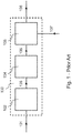
- a typical control system for such trains determines (block 102) a load demand 103 based on a (detected) suction pressure 101 of the compressor, then determines (block 104) a speed setpoint 105 based on the previously-determined load demand 103, and finally determines (block 106) a control signal 108 based on the previously-determined speed setpoint 105 and a (detected) rotation speed 107 of the compressor; the so-determined control signal 108 is fed to a control input of the engine.
- a control system of this type is disclosed, for example, in US patent n° 3,979,655 .
- Such typical control system works well if the effects of disturbances coming from units upstream or downstream the compressor or the effects of interactions between the compressor and said units, on compressor speed and/or on controlled performance variables are consistent; this applies, for example, if the composition of the gas mixture at the inlet of the compressor remains absolutely constant or, at least, quite constant.
- the above-mentioned trains are used, for example, in synthesis plant for the production of ammonia.
- An example of a known process for producing ammonia is the one that may be licensed from KBR that will be called in the following "KBR process".
- a gas mixture (often containing hydrogen and/or nitrogen and/or carbon monoxide) to be processed by the compressor.
- the plant is designed so to maintain the composition of the gas mixture constant, one or more of these units may adversely affect the composition in certain operating conditions.
- purifier including a condensation reformer
- the compressor system including two compressors
- a typical control system implements a control action in the opposite direction to reject the disturbance. For this reason, the control system has to be switched from "automatic mode” or “automatic control” to "manual mode” or “manual control” in order to avoid amplifying the upset and reaching an unstable condition; after some time, the control system is switched back to "automatic mode” or “automatic control”. This means that the control system is semiautomatic.
- First embodiments of the subject matter disclosed herein relate to a control system for a rotary compressor driven by a rotary engine.
- a control system for a rotary compressor driven by a rotary engine comprises: a first control subsystem, a second control subsystem and a selector;
- the first control subsystem comprises: a performance input arranged to receive a first measure signal indicating performance of said rotary compressor, and a first control output arranged to provide a first control signal as a function of said first measure signal;
- the second control subsystem comprises: a speed input arranged to receive a second measure signal indicating rotation speed of said rotary compressor or said rotary engine, and a second control output arranged to provide a second control signal as a function of said second measure signal;
- the selector comprises: a first input electrically connected to said first control output, a second input electrically connected to said second control output, and a third control output arranged to provide a third control signal to a power control input of said rotary engine; said selector is arranged to select said first control signal or said second control signal as said third control signal to be provided at said third control output.
- Second embodiments of the subject matter disclosed herein relate to a synthesis plant.
- the synthesis plant comprises: a rotary compressor comprising an inlet and an outlet, wherein said inlet is arranged to receive a gas mixture, a rotary engine driving said rotary compressor, and a control system as set out above.
- Third embodiments of the subject matter disclosed herein relate to a method of controlling a rotary compressor driven by a rotary engine.
- the method comprises the steps of: measuring a parameter of said rotary compressor, said parameter indicating performance of said rotary compressor, generating a first control signal as a function of said parameter, measuring a rotation speed of said rotary compressor or said rotary engine, generating a second control signal as a function of said rotation speed, generating a third control signal by selecting between said first control signal and said second control signal, and providing said third control signal to control input terminals of said rotary engine.
- a "block” may refer to a piece of hardware or piece of software (running on a piece of hardware), an “input” or an “output” may refer to electrical terminals or a piece of data stored in a computer memory (that may be for example internal to a PLC), the expression “receiving a signal” may mean “letting an electrical signal flow into electrical terminals” or “reading a piece of data from a memory”, the expression “providing an output” may mean “letting an electrical signal flow out of electrical terminals” or “writing a piece of data to a memory”, the expression “electrically connected” (when referred for example to blocks) may correspond to having electrical wires between electrical terminals of a block and electrical terminals of another block or to having a block writing a piece of data to a memory and another block reading the same piece of data from the same memory.
- PLC Programmable Logic Controller
- Figures 2 , 3 , 4 , and 5 illustrate embodiments of a new and inventive fully-automatic control system that adjusts rotational speed of a compressor in response to disturbances, such as, but not limited to, variations in the composition of a gas mixture at an inlet of the compressor.
- the gas mixture may comprise so-called "synthesis gas” that often contains hydrogen and/or nitrogen and/or carbon monoxide.
- the control system together with a controlled train, including a rotary compressor and an engine may be used within a plant to synthesize ammonia from the gas mixture.
- the rotary compressor may be driven by the engine.
- the new full-automatic control system differs from prior control systems in that it includes not one, but at least two control subsystems.
- the first control subsystem performs control based preferably only on a performance parameter of the compressor, in particular its suction pressure.
- the second control subsystem performs control based preferably only on the rotation speed of the engine or the compressor.
- the first control subsystem is used when the rotation speed has a value corresponding to the design (or not too far therefrom); this means for example that the composition of the gas mixture at the inlet of the compressor is as expected (or not too far therefrom).
- the second control subsystem is used the rotation speed is too high or too low; this means for example that the composition of the gas mixture at the inlet of the compressor is far therefrom expected. Therefore, no human intervention is necessary.
- a new control system 200 is arranged to control a rotary compressor driven by a rotary engine.
- Control system 200 may include: a first control subsystem 210, a second control subsystem 220 and a selector 240.
- control subsystem may be implemented in many different ways through various possible combinations of pieces of hardware and pieces of software. If the control system is implemented for example through a single PLC, each or any of the control subsystems may be implemented through a so-called "software module", i.e. a set of software programs or software subroutines cooperating for a specific purpose, running on the PLC.
- software module i.e. a set of software programs or software subroutines cooperating for a specific purpose, running on the PLC.
- Control system 200 has a first input 201, a second input 202 and an output 204.
- First control subsystem 210 comprises: a performance input 211 arranged to receive a first measure signal 21 indicating performance of the rotary compressor, and a first control output 212 arranged to provide a first control signal 26 as a function of signal 21.
- first measure signal 21 indicates suction pressure of the rotary compressor; alternatively, it indicates another performance variable of the compressor such as, for example, discharge pressure of the compressor or net gas (mass or volumetric) flow rate processed by the compressor.
- control signal 26 is a power control signal, in particular a speed control signal (in case there is a direct relation between speed and power generated by the engine).
- the first control signal 26 is a function of only signal 21 (but also of other parameters and constants).
- Second control subsystem 220 comprises: a speed input 221 arranged to receive a second measure signal 22 indicating rotation speed of the rotary compressor or the rotary engine (usually the two rotation speeds are equal or at a fixed ratio), and a second control output 222 arranged to provide a second control signal 27 as a function of signal 22.
- control signal 27 is a power control signal, in particular a speed control signal (in case there is a direct relation between speed and power generated by the engine).
- the second control signal 27 is a function of only signal 22 (but also of other parameters and constants).
- suction pressure of the compressor will be considered the performance variable of the compressor without limiting the generality of the foregoing.
- Selector 240 comprises: a first input 241 electrically connected to the first control output 212, a second input 242 electrically connected to the second control output 222, and a third control output 244 arranged to provide a third control signal 24 to a control input of the rotary engine.
- control signal 24 is a power control signal, in particular a speed control signal (in case there is a direct relation between speed and power generated by the engine).
- control signal 24 may be a signal indicating the opening degree of its steam valve; more in particular, it is the opening percentage of this valve.
- Selector 240 is arranged to select control signal 26 or control signal 27 as control signal 24 to be provided at control output 244.
- Input 211 is electrically connected to input 201 of control system 200; input 221 is electrically connected to input 202 of control system 200; output 244 is electrically connected to output 204 of control system 200.
- Selector 240 may carry out selection of input signals according to one or more predetermined selection criteria. For example, selector 240 may select signal 27 instead of signal 26 if the compressor tends to rotate too quickly or too slowly.
- Selector 240 is advantageously arranged to select signal 27 instead of signal 26 at one or more of the following two conditions:
- condition A applies when the compressor tends to rotate too slowly and condition B applies when the compressor tends to rotate too quickly; anyway, none of the above two conditions is equivalent to a test on the current rotating speed of the compressor.
- Second control subsystem 220 may correspond simply to a PID controller wherein, preferably, only the P term and the I term are used; in this case, the controller may be defined a PI controller.
- Control subsystem 220 may be split into two portions, each of these portions providing a control signal; at a certain time, only one of these two control signals is valid; for example, one is valid if the compressor tends to rotate too quickly and one is valid if the compressor tends to rotate too slowly.
- the selector may be, for example, as selector 440 shown in Fig. 4 .
- Selector 440 has a first input 441 for receiving a control signal 46 from the first control subsystem (for example subsystem 210), a second input 442A for receiving a control signal 47A from a first portion of the second control subsystem (for example subsystem 220), a third input 442B for receiving a control signal 47B from a second portion of the second control subsystem (for example subsystem 220), and an output 444 for providing a control signal 44 selected between signals 46, 47A and 47B.
- control system 500 The embodiment of Fig. 5 , i.e. control system 500, will now be considered.
- Control system 500 comprises a first control subsystem, a second control subsystem and a selector.
- the first control subsystem corresponds to blocks 512, 514 and 516.
- the second control subsystem corresponds to blocks 522, 524, 526 and 528.
- the selector corresponds to selectors 540A and 540B.
- the first control subsystem of the embodiment of Fig. 5 is arranged to calculate a suction pressure error signal 53 as a difference between a suction pressure setpoint 51 and a suction pressure measure signal 52.
- the first control subsystem of the embodiment of Fig. 5 comprises a load controller 514 arranged to determine a load demand 54 based on suction pressure error signal 53; controller 514 is advantageously a PID controller.
- the first control subsystem of the embodiment of Fig. 5 comprises a converter 516 arranged to determine a first power control signal 55-1 based on load demand 54.
- Converter 516 is, in particular, a split converter and is arranged to provide alternatively a first power control signal 55-1 and an anti-surge control signal 93.
- the second control subsystem of the embodiment of Fig. 5 comprises a first speed controller 522 of the PID type (preferably, only the P term and the I term are used; in this case, controller 522 may be defined a PI controller); first speed controller 522 is arranged to determine a second power control signal 55-2A based on a difference between a lower speed limit 57 and a second rotation speed measure signal 56 (obtained through e.g. a subtractor 524), and provide it at an output.
- the second control subsystem of the embodiment of Fig. 5 comprises a second speed controller 526 of the PID type (preferably, only the P term and the I term are used; in this case, controller 526 may be defined a PI controller); second speed controller 526 is arranged to determine a third power control signal 55-2B based on a difference between an upper speed limit 58 a second rotation speed measure signal 56 (obtained through e.g. a subtractor 528), and provide it at an output.
- the second control subsystem of the embodiment of Fig. 5 comprises a first selector 540A for managing control signal 55-2A and a second selector 540B for managing control signal 55-2B.
- selector 540A is arranged to select control signal 55-2A and provide it at output 59A when rotation speed measure signal 56 has a low value, i.e. when rotation speed of the compressor is very low; alternatively, signal 55-1 is provided at output 59A.
- selector 540B is arranged to select control signal 55-2B and provide it at output 59B when rotation speed measure signal 56 has a high value, i.e. when rotation speed of the compressor is very high; alternatively, signal 59A is provided at output 59B.
- selectors 540A and 540B make selections based on comparisons between signals at their inputs; in other words, preferably neither selector 540A nor selector 540B make selections based on a direct test on the current rotation speed of the compressor.
- the embodiment 500 of Fig. 5 comprises an anti-surge control subsystem.
- the anti-surge control subsystem comprises a controller 902 and selector 904.
- Controller 902 determines an anti-surge control signal 92 based on a set 91 of parameters; this set comprises in particular the pressure and the temperature at the inlet of the compressor, the pressure and the temperature at the outlet of the compressor, and the volumetric flow rate processed by the compressor. Such controller may determine an anti-surge control signal in a known way.
- Selector 904 is arranged to receive the anti-surge control signal 92 and another anti-surge control signal 93, and to select one of them as anti-surge control signal 94 to be provide to an anti-surge valve of the compressor; control signal 94 may be a signal indicating the opening degree of the anti-surge valve, more in particular its opening percentage. Selector 904 may select, for example, the anti-surge control signal having higher value.
- Anti-surge control signal 93 is provided by split converter 516.
- Fig. 3 shows a general block diagram applicable to several embodiments of an improved synthesis plant, in particular to an ammonia improved synthesis plant.
- Plant 1000 comprises: a rotary compressor 350, a rotary engine 360 driving the rotary compressor 350, and a control system 300.
- Control system 300 is of the type comprising a first control subsystem and second control subsystem as, for example, the one shown in Fig. 2 .
- the shaft 361 of rotary engine 360 is mechanically directly connected to the shaft 351 of rotary compressor 350.
- Compressor 350 has an inlet 352 for receiving an uncompressed gas mixture flow 38 and an outlet 353 for providing a compressed gas mixture flow 39.
- Control system 300 has a first input 301 for receiving a suction pressure measure signal 31, a second input 302 for receiving a rotation speed measure signal 32, and an output 304 for providing a power control signal 34.
- Output 304 is electrically connected to an input 362 being a power control input of engine 360; typically, by varying power, also rotation speed varies; therefore, engine 360 is a variable-speed rotary engine.
- a pressure sensor 381 that is positioned and configured to monitor uncompressed gas mixture flow 38 and electrically connected to input 301.
- rotation speed sensor 382 that is positioned and configured to monitor shaft 351 and electrically connected to input 302.
- Engine 360 is advantageously a steam turbine; alternatively, it may be, for example, a gas turbine or a (variable-speed) motor such as an electric motor.
- a steam turbine is advantageous as in a synthesis plant heat is generated and a steam turbine allows to recycle some of this generated heat for a useful purpose, i.e. rotating the compressor.
- Synthesis plant 1000 may comprise one or more further compressors.
- two compressors may be fluidly connected in series and may be controlled by the same control system 300 through the same control signal or through the same measure signals.
- a unit 370 for example a reformer (in particular a condensation reformer).
- an outlet 371 of unit 370 is fluidly connected to inlet 352 of compressor 350.
- gas mixture 38 may sometimes vary its composition. This is particular the case if unit 370 is a condensation reformer.
- Synthesis plant 1000 is advantageously a plant for producing ammonia. If the synthesis plant 1000 were licensed to perform the KBR ammonia process, then a purifier arrangement including a condensation reformer is typically placed upstream the synthesis gas compressor arrangement. Although the purifier arrangement would be configured to maintain the composition of the output gas mixture constant, it could do so only to a certain extent and not at all times for any operating condition of the plant, unless the synthesis plant 1000 was built or upgraded to include an embodiment of the new two-subsystem control system described, shown and claimed herein.
- so-called “syngas” may be used in several synthesis processes, for example in order to synthetize ammonia, methanol, etc.
- Fig. 6 shows a flow chart 600 of an embodiment of a method of controlling a rotary compressor, such as for example compressor 350 in Fig. 3 , driven by a rotary engine, such as for example steam turbine 360 in Fig. 3 .
- a rotary compressor such as for example compressor 350 in Fig. 3
- a rotary engine such as for example steam turbine 360 in Fig. 3 .
- Block 601 corresponds to the start of a control process.
- Block 608 corresponds to the end of the control process.
- the activities corresponding to blocks from 602 to 607 are cyclically repeated.
- Block 602 corresponds to measuring a parameter of the rotary compressor indicating performance of the rotary compressor; in embodiment of Fig. 3 for example, sensor 381 measures a suction pressure of compressor 350.
- Block 603 corresponds to generating a first control signal as a function of this parameter; in embodiment of Fig.3 for example, this activity is carried out by control system 300 internally thereto (see for example Fig. 2 ).
- Block 604 corresponds to measuring a rotation speed of the rotary compressor or the rotary engine; in embodiment of Fig. 3 for example, sensor 382 measures a rotation speed of a single shaft that is both a shaft 361 of steam turbine 360 and a shaft 351 of compressor 350.
- Block 605 corresponds to generating a second control signal as a function of the rotation speed; in embodiment of Fig.3 for example, this activity is carried out by control system 300 internally thereto (see for example Fig. 2 ).
- Block 606 corresponds to generating a third control signal by selecting between the first control signal and the second control signal; in embodiment of Fig.3 for example, this activity is carried out by control system 300 internally thereto (see for example Fig. 2 ).
- Block 607 corresponds to providing the third control signal to control input terminals of the rotary engine; in embodiment of Fig.3 for example, this activity corresponds to electrically connecting output terminals 304 of control system 300 to control terminals 362 of steam turbine 360.
- the second control signal may be selected instead of the first control signal at one or more of at least the following conditions:
Landscapes
- Engineering & Computer Science (AREA)
- Mechanical Engineering (AREA)
- General Engineering & Computer Science (AREA)
- Physics & Mathematics (AREA)
- General Physics & Mathematics (AREA)
- Automation & Control Theory (AREA)
- Combustion & Propulsion (AREA)
- Chemical & Material Sciences (AREA)
- Fluid Mechanics (AREA)
- Power Engineering (AREA)
- Sustainable Development (AREA)
- Life Sciences & Earth Sciences (AREA)
- Control Of Positive-Displacement Air Blowers (AREA)
- Control Of Positive-Displacement Pumps (AREA)
Claims (15)
- Steuerungssystem (200) für einen Rotationsverdichter, der durch eine Rotationsmaschine angetrieben wird, wobei das Steuerungssystem (200) umfasst:A) ein erstes Steuerungssubsystem (210), umfassend:- einen Leistungseingang (211), der zum Empfangen eines ersten Messsignals (21), das die Leistung des Rotationsverdichters angibt, angeordnet ist, und- einen ersten Steuerungsausgang (212), der dazu angeordnet ist, ein erstes Steuersignal (26) in Abhängigkeit vom ersten Messsignal (21) bereitzustellen;B) ein zweites Steuerungssubsystem (220), umfassend:- einen Drehzahleingang (221), der zum Empfangen eines zweiten Messsignals (22), das die Drehzahl des Rotationsverdichters oder der Rotationsmaschine angibt, angeordnet ist, und- einen zweiten Steuerungsausgang (222), der dazu angeordnet ist, ein zweites Steuersignal (27) in Abhängigkeit vom zweiten Messsignal (22) bereitzustellen;
dadurch gekennzeichnet, dass das Steuerungssystem (200) ferner umfasst:C) einen Selektor (240), umfassend:- einen ersten Eingang (241), der mit dem ersten Steuerungsausgang (212) elektrisch verbunden ist,- einen zweiten Eingang (242), der mit dem zweiten Steuerungsausgang (222) elektrisch verbunden ist, und- einen dritten Steuerungsausgang (244), der dazu angeordnet ist, ein drittes Steuersignal (24) an einen Leistungssteuerungseingang der Rotationsmaschine bereitzustellen;,
wobei der Selektor (240) dazu angeordnet ist, das erste Steuersignal (26) oder das zweite Steuersignal (27) als das dritte Steuersignal (24) auszuwählen, das an dem dritten Steuerungsausgang (244) bereitzustellen ist. - Steuerungssystem (200) nach Anspruch 1, wobei der Selektor (240) dazu angeordnet ist, das zweite Steuersignal (27) anstelle des ersten Steuersignals (26) bei einer oder mehreren von mindestens den folgenden Bedingungen auszuwählen:- das zweite Steuersignal (27) ist höher als das erste Steuersignal (26),- das zweite Steuersignal (27) ist niedriger als das erste Steuersignal (26).
- Steuerungssystem (500) nach Anspruch 1 oder Anspruch 2, wobei das zweite Steuerungssubsystem einen ersten Drehzahlregler (522) vom PID-Typ umfasst, wobei vorzugsweise nur der P-Term und der I-Term verwendet werden, wobei der erste Drehzahlregler (522) angeordnet ist zum Bestimmen eines Steuersignals (55-2A) basierend auf dem zweiten Messsignal (56) und einer unteren Drehzahlbegrenzung (57), und Bereitstellen an einem Ausgang.
- Steuerungssystem (500) nach einem der vorstehenden Ansprüche, umfassend einen ersten Selektor (540A), der angeordnet ist zum Auswählen des Steuersignals (55-2A) an dem Ausgang des ersten Drehzahlreglers (522), wenn das zweite Messsignal (56) einen niedrigen Wert aufweist.
- Steuerungssystem (500) nach einem der vorstehenden Ansprüche, wobei das zweite Steuerungssubsystem einen zweiten Drehzahlregler (526) vom PID-Typ umfasst, wobei vorzugsweise nur der P-Term und der I-Term verwendet werden, wobei der zweite Drehzahlregler (526) angeordnet ist zum Bestimmen eines Steuersignals (55-2B) basierend auf dem zweiten Messsignal (56) und einer oberen Drehzahlbegrenzung (58), und Bereitstellen an einem Ausgang.
- Steuerungssystem (500) nach einem der vorstehenden Ansprüche, umfassend einen zweiten Selektor (540B), der angeordnet ist zum Auswählen des Steuersignals (55-2B) an dem Ausgang des zweiten Drehzahlreglers (526), wenn das zweite Messsignal (56) einen hohen Wert aufweist.
- Steuerungssystem (500) nach einem der vorstehenden Ansprüche, wobei das erste Steuerungssubsystem angeordnet ist zum Berechnen eines Leistungsfehlersignals (53) als eine Differenz zwischen einem Leistungssollwert (51) und dem ersten Messsignal (52).
- Steuerungssystem (500) nach einem der vorstehenden Ansprüche, wobei das erste Steuerungssubsystem eine Laststeuerung (514) umfasst, die dazu angeordnet ist, eine Lastanforderung (54) basierend auf dem Leistungsfehlersignal (53) zu bestimmen.
- Steuerungssystem (500) nach einem der vorstehenden Ansprüche, wobei das erste Steuerungssubsystem einen Wandler (516) umfasst, der angeordnet ist, um ein Steuersignal (55- 1) basierend auf der Lastanforderung (54) zu bestimmen.
- Steuerungssystem (500) nach einem der vorstehenden Ansprüche, wobei der Wandler (516) ein Split-Konverter (geteilter Wandler) ist und dazu angeordnet ist, alternativ ein Steuersignal (55-1) und ein Überspannungsschutz-Steuersignal (93) bereitzustellen.
- Steuerungssystem (500) nach einem der vorstehenden Ansprüche, wobei der Leistungseingang (211) des ersten und/oder des zweiten Subsystems (210) dazu angeordnet ist, ein Messsignal (21) zu empfangen, das den Ansaugdruck des Rotationsverdichters angibt.
- Syntheseanlage (1000), umfassend:- einen Rotationsverdichter (350), umfassend einen Einlass (352) und einen Auslass (353), wobei der Einlass (352) dazu angeordnet ist, ein Gasgemisch (38) aufzunehmen;- eine Rotationsmaschine (360), die den Rotationsverdichter (350) antreibt; und- ein Steuerungssystem (300) nach einem der vorstehenden Ansprüche.
- Anlage (1000) nach Anspruch 12, wobei die Rotationsmaschine (360) eine Dampfturbine ist.
- Anlage (1000) nach Anspruch 12 oder 13, umfassend einen dem Rotationsverdichter (350) vorgelagerten Reformer (370), wobei der Reformer (370) einen Auslass (371) umfasst, der fluidisch mit dem Einlass (352) des Rotationsverdichters (350) verbunden ist.
- Verfahren (600) zum Steuern eines Rotationsverdichters, der durch eine Rotationsmaschine angetrieben wird, umfassend die folgenden Schritte:A) Messen (602) eines Parameters des Rotationsverdichters, wobei der Parameter die Leistung des Rotationsverdichters angibt,B) Generieren (603) eines ersten Steuersignals in Abhängigkeit von dem Parameter,C) Messen (604) einer Drehzahl des Rotationsverdichters oder der Rotationsmaschine,D) Generieren (605) eines zweiten Steuersignals in Abhängigkeit von der Drehzahl,
dadurch gekennzeichnet, dass das Verfahren (600) ferner folgende Schritte umfasst:E) Generieren (606) eines dritten Steuersignals durch Auswählen zwischen dem ersten Steuersignal und dem zweiten Steuersignal, undF) Bereitstellen (607) des dritten Steuersignals an Steuereingangsanschlüsse der Rotationsmaschine.
Applications Claiming Priority (1)
| Application Number | Priority Date | Filing Date | Title |
|---|---|---|---|
| IT102017000100734A IT201700100734A1 (it) | 2017-09-08 | 2017-09-08 | Sistema di controllo per un compressore con sottosistema basato sulla velocita’, impianto di sintesi e metodo di controllo / control system for a compressor with speed-based subsystem, synthesis plant and control method |
Publications (2)
| Publication Number | Publication Date |
|---|---|
| EP3454162A1 EP3454162A1 (de) | 2019-03-13 |
| EP3454162B1 true EP3454162B1 (de) | 2020-07-08 |
Family
ID=60813898
Family Applications (1)
| Application Number | Title | Priority Date | Filing Date |
|---|---|---|---|
| EP18192577.7A Active EP3454162B1 (de) | 2017-09-08 | 2018-09-04 | Steuerungssystem für einen verdichter mit drehzahlbasiertem subsystem, syntheseanlage und steuerungsverfahren |
Country Status (6)
| Country | Link |
|---|---|
| US (1) | US20190078575A1 (de) |
| EP (1) | EP3454162B1 (de) |
| JP (1) | JP7221619B2 (de) |
| KR (1) | KR102542737B1 (de) |
| CN (1) | CN109469639B (de) |
| IT (1) | IT201700100734A1 (de) |
Families Citing this family (1)
| Publication number | Priority date | Publication date | Assignee | Title |
|---|---|---|---|---|
| IT201600070842A1 (it) * | 2016-07-07 | 2018-01-07 | Nuovo Pignone Tecnologie Srl | Metodo e sistema di controllo anti-pompaggio adattivo |
Family Cites Families (14)
| Publication number | Priority date | Publication date | Assignee | Title |
|---|---|---|---|---|
| JPS5032886B2 (de) * | 1972-03-31 | 1975-10-25 | ||
| US3979655A (en) * | 1975-03-31 | 1976-09-07 | Compressor Controls Corporation | Control system for controlling a dynamic compressor |
| US4102604A (en) * | 1977-05-04 | 1978-07-25 | Compressor Controls Corporation | Method and apparatus for noninteracting control of a dynamic compressor having rotating vanes |
| US4218191A (en) * | 1978-11-29 | 1980-08-19 | Phillips Petroleum Company | Multi-constraint control of a compression system |
| US5709526A (en) * | 1996-01-02 | 1998-01-20 | Woodward Governor Company | Surge recurrence prevention control system for dynamic compressors |
| JP3205561B2 (ja) * | 1996-01-02 | 2001-09-04 | ウッドウォード ガヴァナー カンパニー | ダイナミックコンプレッサーのためのサージ防止制御システム |
| JP2001107742A (ja) | 1999-10-13 | 2001-04-17 | Toshiba Corp | ガス化発電プラントの制御装置 |
| JP2002364312A (ja) * | 2001-06-01 | 2002-12-18 | Hitachi Ltd | 石炭ガス化燃料電池複合発電プラントおよびその運転方法 |
| JP4657800B2 (ja) | 2005-05-16 | 2011-03-23 | 本田技研工業株式会社 | 航空機用ガスタービン・エンジンの制御装置 |
| JP4458085B2 (ja) * | 2006-11-30 | 2010-04-28 | 東京電力株式会社 | ガスタービン制御装置 |
| US8047809B2 (en) * | 2007-04-30 | 2011-11-01 | General Electric Company | Modular air compression apparatus with separate platform arrangement |
| JP5721317B2 (ja) | 2009-06-12 | 2015-05-20 | 三菱日立パワーシステムズ株式会社 | 石炭ガス化炉設備及びその制御方法並びにプログラム、及びこれを備えた石炭ガス化複合発電装置 |
| JP2015193571A (ja) * | 2014-03-31 | 2015-11-05 | 三菱重工業株式会社 | 芳香族化合物の製造システム及びその製造方法 |
| JP6376370B2 (ja) * | 2014-08-08 | 2018-08-22 | 東洋システム株式会社 | フィードバック制御装置 |
-
2017
- 2017-09-08 IT IT102017000100734A patent/IT201700100734A1/it unknown
-
2018
- 2018-08-23 US US16/110,775 patent/US20190078575A1/en not_active Abandoned
- 2018-08-30 KR KR1020180102523A patent/KR102542737B1/ko active Active
- 2018-09-04 EP EP18192577.7A patent/EP3454162B1/de active Active
- 2018-09-05 JP JP2018165915A patent/JP7221619B2/ja active Active
- 2018-09-10 CN CN201811050257.2A patent/CN109469639B/zh active Active
Non-Patent Citations (1)
| Title |
|---|
| None * |
Also Published As
| Publication number | Publication date |
|---|---|
| JP2019070382A (ja) | 2019-05-09 |
| CN109469639B (zh) | 2022-04-26 |
| KR102542737B1 (ko) | 2023-06-12 |
| US20190078575A1 (en) | 2019-03-14 |
| KR20190028294A (ko) | 2019-03-18 |
| IT201700100734A1 (it) | 2019-03-08 |
| EP3454162A1 (de) | 2019-03-13 |
| JP7221619B2 (ja) | 2023-02-14 |
| CN109469639A (zh) | 2019-03-15 |
Similar Documents
| Publication | Publication Date | Title |
|---|---|---|
| EP3454163B1 (de) | Steuerungssystem für einen verdichter mit druckbasiertem untersystem, syntheseanlage und steuerungsverfahren | |
| EP1286031B1 (de) | Steuerungsvorrichtung einer Gasturbine | |
| US20160222816A1 (en) | Correction system and method for gas turbine proportional droop governor | |
| KR20110140105A (ko) | 압축기 입구에서 가동성 입구 가이드 베인들을 사용하는 터보익스팬더 및 방법 | |
| CN107103167B (zh) | 针对甩负荷工况的deh调速功能诊断方法及系统 | |
| JP2006522252A (ja) | 複数の圧縮機を備えた圧縮空気装置を制御する方法、それに使用する制御ボックス、および前記方法を使用する圧縮空気装置 | |
| US10550716B2 (en) | Gas turbine inlet guide vane control device, system and control method | |
| CA2885214A1 (en) | Compressed gas production and control | |
| WO2014158335A1 (en) | Systems and methods of droop response control of turbines | |
| EP3454162B1 (de) | Steuerungssystem für einen verdichter mit drehzahlbasiertem subsystem, syntheseanlage und steuerungsverfahren | |
| EP3064746B1 (de) | Systeme und verfahren für turbinensystembetrieb bei niedrigen umgebungstemperaturen | |
| CN108351621A (zh) | 用于工业涡轮机的自适应多输入多输出pid控制系统 | |
| US20130147208A1 (en) | Gas turbine control device and generating system | |
| CN110945227A (zh) | 旋转机械的控制装置、旋转机械设备、旋转机械的控制方法及旋转机械的控制程序 | |
| US10519964B2 (en) | System and method for turbomachinery rotor and blade prognostics and diagnostics | |
| CN119668086A (zh) | 一种比例积分微分回路控制方法及相关装置 | |
| JP7206143B2 (ja) | 1軸式ガスタービンの運転制御装置、運転制御方法及びプログラム | |
| US20120247113A1 (en) | System and method for air extraction from gas turbine engines | |
| CN102953837B (zh) | 燃气轮机装置、其控制装置以及其控制方法 | |
| CN115291499B (zh) | 一种取小值控制方法和控制系统 | |
| CN118775240A (zh) | 调节压缩机的入口压力的方法、系统以及介质 | |
| KR20200051031A (ko) | 증기 터빈 제어 | |
| CN121364626A (zh) | 一种基于指令微分前馈的伺服控制方法及系统 | |
| EP1835592A1 (de) | Verfahren und System um eine kombinierte elektrische Anlage zu Steuern, insbesondere Einwellenanlage |
Legal Events
| Date | Code | Title | Description |
|---|---|---|---|
| PUAI | Public reference made under article 153(3) epc to a published international application that has entered the european phase |
Free format text: ORIGINAL CODE: 0009012 |
|
| STAA | Information on the status of an ep patent application or granted ep patent |
Free format text: STATUS: THE APPLICATION HAS BEEN PUBLISHED |
|
| AK | Designated contracting states |
Kind code of ref document: A1 Designated state(s): AL AT BE BG CH CY CZ DE DK EE ES FI FR GB GR HR HU IE IS IT LI LT LU LV MC MK MT NL NO PL PT RO RS SE SI SK SM TR |
|
| AX | Request for extension of the european patent |
Extension state: BA ME |
|
| STAA | Information on the status of an ep patent application or granted ep patent |
Free format text: STATUS: REQUEST FOR EXAMINATION WAS MADE |
|
| 17P | Request for examination filed |
Effective date: 20190911 |
|
| RBV | Designated contracting states (corrected) |
Designated state(s): AL AT BE BG CH CY CZ DE DK EE ES FI FR GB GR HR HU IE IS IT LI LT LU LV MC MK MT NL NO PL PT RO RS SE SI SK SM TR |
|
| RIC1 | Information provided on ipc code assigned before grant |
Ipc: F04D 27/00 20060101ALI20191219BHEP Ipc: G05D 16/20 20060101AFI20191219BHEP Ipc: G05B 11/32 20060101ALI20191219BHEP |
|
| GRAP | Despatch of communication of intention to grant a patent |
Free format text: ORIGINAL CODE: EPIDOSNIGR1 |
|
| STAA | Information on the status of an ep patent application or granted ep patent |
Free format text: STATUS: GRANT OF PATENT IS INTENDED |
|
| INTG | Intention to grant announced |
Effective date: 20200130 |
|
| GRAS | Grant fee paid |
Free format text: ORIGINAL CODE: EPIDOSNIGR3 |
|
| GRAA | (expected) grant |
Free format text: ORIGINAL CODE: 0009210 |
|
| STAA | Information on the status of an ep patent application or granted ep patent |
Free format text: STATUS: THE PATENT HAS BEEN GRANTED |
|
| RAP1 | Party data changed (applicant data changed or rights of an application transferred) |
Owner name: NUOVO PIGNONE TECNOLOGIE - S.R.L. |
|
| AK | Designated contracting states |
Kind code of ref document: B1 Designated state(s): AL AT BE BG CH CY CZ DE DK EE ES FI FR GB GR HR HU IE IS IT LI LT LU LV MC MK MT NL NO PL PT RO RS SE SI SK SM TR |
|
| REG | Reference to a national code |
Ref country code: CH Ref legal event code: EP Ref country code: AT Ref legal event code: REF Ref document number: 1289133 Country of ref document: AT Kind code of ref document: T Effective date: 20200715 |
|
| REG | Reference to a national code |
Ref country code: DE Ref legal event code: R096 Ref document number: 602018005855 Country of ref document: DE |
|
| REG | Reference to a national code |
Ref country code: IE Ref legal event code: FG4D |
|
| REG | Reference to a national code |
Ref country code: LT Ref legal event code: MG4D |
|
| REG | Reference to a national code |
Ref country code: AT Ref legal event code: MK05 Ref document number: 1289133 Country of ref document: AT Kind code of ref document: T Effective date: 20200708 |
|
| REG | Reference to a national code |
Ref country code: NL Ref legal event code: MP Effective date: 20200708 |
|
| PG25 | Lapsed in a contracting state [announced via postgrant information from national office to epo] |
Ref country code: NO Free format text: LAPSE BECAUSE OF FAILURE TO SUBMIT A TRANSLATION OF THE DESCRIPTION OR TO PAY THE FEE WITHIN THE PRESCRIBED TIME-LIMIT Effective date: 20201008 Ref country code: ES Free format text: LAPSE BECAUSE OF FAILURE TO SUBMIT A TRANSLATION OF THE DESCRIPTION OR TO PAY THE FEE WITHIN THE PRESCRIBED TIME-LIMIT Effective date: 20200708 Ref country code: GR Free format text: LAPSE BECAUSE OF FAILURE TO SUBMIT A TRANSLATION OF THE DESCRIPTION OR TO PAY THE FEE WITHIN THE PRESCRIBED TIME-LIMIT Effective date: 20201009 Ref country code: HR Free format text: LAPSE BECAUSE OF FAILURE TO SUBMIT A TRANSLATION OF THE DESCRIPTION OR TO PAY THE FEE WITHIN THE PRESCRIBED TIME-LIMIT Effective date: 20200708 Ref country code: SE Free format text: LAPSE BECAUSE OF FAILURE TO SUBMIT A TRANSLATION OF THE DESCRIPTION OR TO PAY THE FEE WITHIN THE PRESCRIBED TIME-LIMIT Effective date: 20200708 Ref country code: FI Free format text: LAPSE BECAUSE OF FAILURE TO SUBMIT A TRANSLATION OF THE DESCRIPTION OR TO PAY THE FEE WITHIN THE PRESCRIBED TIME-LIMIT Effective date: 20200708 Ref country code: LT Free format text: LAPSE BECAUSE OF FAILURE TO SUBMIT A TRANSLATION OF THE DESCRIPTION OR TO PAY THE FEE WITHIN THE PRESCRIBED TIME-LIMIT Effective date: 20200708 Ref country code: AT Free format text: LAPSE BECAUSE OF FAILURE TO SUBMIT A TRANSLATION OF THE DESCRIPTION OR TO PAY THE FEE WITHIN THE PRESCRIBED TIME-LIMIT Effective date: 20200708 Ref country code: BG Free format text: LAPSE BECAUSE OF FAILURE TO SUBMIT A TRANSLATION OF THE DESCRIPTION OR TO PAY THE FEE WITHIN THE PRESCRIBED TIME-LIMIT Effective date: 20201008 Ref country code: PT Free format text: LAPSE BECAUSE OF FAILURE TO SUBMIT A TRANSLATION OF THE DESCRIPTION OR TO PAY THE FEE WITHIN THE PRESCRIBED TIME-LIMIT Effective date: 20201109 |
|
| PG25 | Lapsed in a contracting state [announced via postgrant information from national office to epo] |
Ref country code: RS Free format text: LAPSE BECAUSE OF FAILURE TO SUBMIT A TRANSLATION OF THE DESCRIPTION OR TO PAY THE FEE WITHIN THE PRESCRIBED TIME-LIMIT Effective date: 20200708 Ref country code: PL Free format text: LAPSE BECAUSE OF FAILURE TO SUBMIT A TRANSLATION OF THE DESCRIPTION OR TO PAY THE FEE WITHIN THE PRESCRIBED TIME-LIMIT Effective date: 20200708 Ref country code: LV Free format text: LAPSE BECAUSE OF FAILURE TO SUBMIT A TRANSLATION OF THE DESCRIPTION OR TO PAY THE FEE WITHIN THE PRESCRIBED TIME-LIMIT Effective date: 20200708 Ref country code: IS Free format text: LAPSE BECAUSE OF FAILURE TO SUBMIT A TRANSLATION OF THE DESCRIPTION OR TO PAY THE FEE WITHIN THE PRESCRIBED TIME-LIMIT Effective date: 20201108 |
|
| PG25 | Lapsed in a contracting state [announced via postgrant information from national office to epo] |
Ref country code: NL Free format text: LAPSE BECAUSE OF FAILURE TO SUBMIT A TRANSLATION OF THE DESCRIPTION OR TO PAY THE FEE WITHIN THE PRESCRIBED TIME-LIMIT Effective date: 20200708 |
|
| REG | Reference to a national code |
Ref country code: DE Ref legal event code: R097 Ref document number: 602018005855 Country of ref document: DE |
|
| PG25 | Lapsed in a contracting state [announced via postgrant information from national office to epo] |
Ref country code: CZ Free format text: LAPSE BECAUSE OF FAILURE TO SUBMIT A TRANSLATION OF THE DESCRIPTION OR TO PAY THE FEE WITHIN THE PRESCRIBED TIME-LIMIT Effective date: 20200708 Ref country code: DK Free format text: LAPSE BECAUSE OF FAILURE TO SUBMIT A TRANSLATION OF THE DESCRIPTION OR TO PAY THE FEE WITHIN THE PRESCRIBED TIME-LIMIT Effective date: 20200708 Ref country code: RO Free format text: LAPSE BECAUSE OF FAILURE TO SUBMIT A TRANSLATION OF THE DESCRIPTION OR TO PAY THE FEE WITHIN THE PRESCRIBED TIME-LIMIT Effective date: 20200708 Ref country code: EE Free format text: LAPSE BECAUSE OF FAILURE TO SUBMIT A TRANSLATION OF THE DESCRIPTION OR TO PAY THE FEE WITHIN THE PRESCRIBED TIME-LIMIT Effective date: 20200708 Ref country code: SM Free format text: LAPSE BECAUSE OF FAILURE TO SUBMIT A TRANSLATION OF THE DESCRIPTION OR TO PAY THE FEE WITHIN THE PRESCRIBED TIME-LIMIT Effective date: 20200708 Ref country code: IT Free format text: LAPSE BECAUSE OF FAILURE TO SUBMIT A TRANSLATION OF THE DESCRIPTION OR TO PAY THE FEE WITHIN THE PRESCRIBED TIME-LIMIT Effective date: 20200708 |
|
| PLBE | No opposition filed within time limit |
Free format text: ORIGINAL CODE: 0009261 |
|
| STAA | Information on the status of an ep patent application or granted ep patent |
Free format text: STATUS: NO OPPOSITION FILED WITHIN TIME LIMIT |
|
| PG25 | Lapsed in a contracting state [announced via postgrant information from national office to epo] |
Ref country code: AL Free format text: LAPSE BECAUSE OF FAILURE TO SUBMIT A TRANSLATION OF THE DESCRIPTION OR TO PAY THE FEE WITHIN THE PRESCRIBED TIME-LIMIT Effective date: 20200708 |
|
| 26N | No opposition filed |
Effective date: 20210409 |
|
| REG | Reference to a national code |
Ref country code: BE Ref legal event code: MM Effective date: 20200930 |
|
| PG25 | Lapsed in a contracting state [announced via postgrant information from national office to epo] |
Ref country code: LU Free format text: LAPSE BECAUSE OF NON-PAYMENT OF DUE FEES Effective date: 20200904 Ref country code: SK Free format text: LAPSE BECAUSE OF FAILURE TO SUBMIT A TRANSLATION OF THE DESCRIPTION OR TO PAY THE FEE WITHIN THE PRESCRIBED TIME-LIMIT Effective date: 20200708 |
|
| PG25 | Lapsed in a contracting state [announced via postgrant information from national office to epo] |
Ref country code: BE Free format text: LAPSE BECAUSE OF NON-PAYMENT OF DUE FEES Effective date: 20200930 Ref country code: SI Free format text: LAPSE BECAUSE OF FAILURE TO SUBMIT A TRANSLATION OF THE DESCRIPTION OR TO PAY THE FEE WITHIN THE PRESCRIBED TIME-LIMIT Effective date: 20200708 Ref country code: IE Free format text: LAPSE BECAUSE OF NON-PAYMENT OF DUE FEES Effective date: 20200904 |
|
| REG | Reference to a national code |
Ref country code: CH Ref legal event code: PL |
|
| PG25 | Lapsed in a contracting state [announced via postgrant information from national office to epo] |
Ref country code: TR Free format text: LAPSE BECAUSE OF FAILURE TO SUBMIT A TRANSLATION OF THE DESCRIPTION OR TO PAY THE FEE WITHIN THE PRESCRIBED TIME-LIMIT Effective date: 20200708 Ref country code: MT Free format text: LAPSE BECAUSE OF FAILURE TO SUBMIT A TRANSLATION OF THE DESCRIPTION OR TO PAY THE FEE WITHIN THE PRESCRIBED TIME-LIMIT Effective date: 20200708 Ref country code: CY Free format text: LAPSE BECAUSE OF FAILURE TO SUBMIT A TRANSLATION OF THE DESCRIPTION OR TO PAY THE FEE WITHIN THE PRESCRIBED TIME-LIMIT Effective date: 20200708 |
|
| PG25 | Lapsed in a contracting state [announced via postgrant information from national office to epo] |
Ref country code: MK Free format text: LAPSE BECAUSE OF FAILURE TO SUBMIT A TRANSLATION OF THE DESCRIPTION OR TO PAY THE FEE WITHIN THE PRESCRIBED TIME-LIMIT Effective date: 20200708 Ref country code: MC Free format text: LAPSE BECAUSE OF FAILURE TO SUBMIT A TRANSLATION OF THE DESCRIPTION OR TO PAY THE FEE WITHIN THE PRESCRIBED TIME-LIMIT Effective date: 20200708 |
|
| PG25 | Lapsed in a contracting state [announced via postgrant information from national office to epo] |
Ref country code: LI Free format text: LAPSE BECAUSE OF NON-PAYMENT OF DUE FEES Effective date: 20210930 Ref country code: CH Free format text: LAPSE BECAUSE OF NON-PAYMENT OF DUE FEES Effective date: 20210930 |
|
| GBPC | Gb: european patent ceased through non-payment of renewal fee |
Effective date: 20220904 |
|
| P01 | Opt-out of the competence of the unified patent court (upc) registered |
Effective date: 20230526 |
|
| PG25 | Lapsed in a contracting state [announced via postgrant information from national office to epo] |
Ref country code: GB Free format text: LAPSE BECAUSE OF NON-PAYMENT OF DUE FEES Effective date: 20220904 |
|
| PGFP | Annual fee paid to national office [announced via postgrant information from national office to epo] |
Ref country code: DE Payment date: 20250820 Year of fee payment: 8 |
|
| PGFP | Annual fee paid to national office [announced via postgrant information from national office to epo] |
Ref country code: FR Payment date: 20250820 Year of fee payment: 8 |