EP3454140A1 - Dispositif horloger astronomique - Google Patents
Dispositif horloger astronomique Download PDFInfo
- Publication number
- EP3454140A1 EP3454140A1 EP17190158.0A EP17190158A EP3454140A1 EP 3454140 A1 EP3454140 A1 EP 3454140A1 EP 17190158 A EP17190158 A EP 17190158A EP 3454140 A1 EP3454140 A1 EP 3454140A1
- Authority
- EP
- European Patent Office
- Prior art keywords
- star
- watch device
- needle
- watch
- horizontal plane
- Prior art date
- Legal status (The legal status is an assumption and is not a legal conclusion. Google has not performed a legal analysis and makes no representation as to the accuracy of the status listed.)
- Granted
Links
Images

Classifications
-
- G—PHYSICS
- G04—HOROLOGY
- G04G—ELECTRONIC TIME-PIECES
- G04G9/00—Visual time or date indication means
- G04G9/0064—Visual time or date indication means in which functions not related to time can be displayed
-
- G—PHYSICS
- G04—HOROLOGY
- G04B—MECHANICALLY-DRIVEN CLOCKS OR WATCHES; MECHANICAL PARTS OF CLOCKS OR WATCHES IN GENERAL; TIME PIECES USING THE POSITION OF THE SUN, MOON OR STARS
- G04B19/00—Indicating the time by visual means
- G04B19/26—Clocks or watches with indicators for tides, for the phases of the moon, or the like
- G04B19/262—Clocks or watches with indicators for tides, for the phases of the moon, or the like with indicators for astrological informations
-
- G—PHYSICS
- G04—HOROLOGY
- G04B—MECHANICALLY-DRIVEN CLOCKS OR WATCHES; MECHANICAL PARTS OF CLOCKS OR WATCHES IN GENERAL; TIME PIECES USING THE POSITION OF THE SUN, MOON OR STARS
- G04B47/00—Time-pieces combined with other articles which do not interfere with the running or the time-keeping of the time-piece
-
- G—PHYSICS
- G04—HOROLOGY
- G04G—ELECTRONIC TIME-PIECES
- G04G21/00—Input or output devices integrated in time-pieces
- G04G21/04—Input or output devices integrated in time-pieces using radio waves
-
- G—PHYSICS
- G04—HOROLOGY
- G04G—ELECTRONIC TIME-PIECES
- G04G9/00—Visual time or date indication means
- G04G9/0064—Visual time or date indication means in which functions not related to time can be displayed
- G04G9/007—Visual time or date indication means in which functions not related to time can be displayed combined with a calculator or computing means
Definitions
- the invention relates to an astronomical horological device, for example a wristwatch, capable of indicating the position of a star of the solar system.
- Such a watch is known for example from the document EP 0 949 549 , which describes a watch adapted to display the position of a star (planets or sun) in the Zodiac at the current date or another date.
- the watch comprises a dial in the shape of a crown which carries at its periphery a graduation in hours and in minutes and inside thereof the symbols of the twelve signs of the Zodiac. , as well as the representations of the four main phases of the Moon.
- the watch also includes a rotating bezel on which are represented by symbols the stars that can be selected by rotating the bezel to position the symbol of the star chosen at 12H.
- the position of the body selected in a Zodiac sign is then calculated and displayed by positioning the minute hand in a position where it simultaneously indicates the sign of the Zodiac in which the star is selected and the approximate position of the latter within the sign of the Zodiac in question, respectively using the symbols 18 and the graduation in hours and minutes 17 of the dial 16.
- Such a watch makes it possible to display the sign of the Zodiac in which there is a star and the position of said star in said sign of the Zodiac at a given date.
- it does not allow a user to easily find the star selected in the sky if he does not know how to locate the sign of the Zodiac concerned.
- reading this information is not always easy.
- the clock device thus directly displays the position in the sky of the star sought.
- the user can then view the star directly in the sky, following the directions given by the hands of the display system.
- the position of the star is defined in a horizontal coordinate system centered on the watch device by an azimuth ( ⁇ A ) and an elevation angle ( ⁇ A ), defined by a horizontal plane ( X 0 , Y 0 ) and a vertical axis (Z 0 ), horizontal plane comprising an axis cardinal (X 0 ), the needle control means being adapted to determine a cardinal axis in the horizontal plane and to orient a first needle relative to the cardinal axis according to the determined azimuth of the star.
- the azimuth of the star in space is thus directly accessible for the user who can easily orient in the horizontal plane.
- the needle control means can be adapted to position a second needle, in the horizontal plane and with respect to a reference axis (X M ) connected to the watch device, at an angle ⁇ equal to 1 elevation angle ⁇ A of the star.
- the needle control means may be adapted to orient the second needle relative to the horizontal plane according to the determined elevation angle ⁇ A of the star.
- the watch device may also include means for selecting a star from a plurality of stars.
- the clock device is of the wristwatch type, facilitating a nomadic use.
- the invention relates to a watch device adapted to indicate the position of a star.
- the watch device is a wristwatch, but other clock devices can be envisaged, such as a pocket watch, a chronometer, etc.
- the Y axis M points in the direction of a graduation of the dial corresponding to 12H and the X axis M points in the direction of a graduation of the dial corresponding to 3H.
- X M and Y M define the main plane of the watch device.
- the circuit 1 is made according to a conventional scheme in the watchmaking environment; it essentially comprises a time base for producing a standard frequency signal and a circuit adapted to determine the current time from said standard frequency signal.
- the positioning circuit 2 is also known elsewhere; it is for example a GPS chip (for Global Positioning System) or equivalent, able to determine a geographical position on the Earth from signals it receives from a satellite positioning system.
- GPS chip for Global Positioning System
- the means 4 essentially comprise a data memory 4a, a program memory 4b, and a processing unit 4c.
- the data memory 4 may in particular comprise a sky map stored in the form of a database comprising a list of the stars (at least one star) that can be pointed and, for each identified star, data representative of its position in the solar system relative to the earth. From a practical point of view, the data memory can be positioned in the immediate vicinity of the processing unit 4c, in a case of the watch device. Alternatively, all or part of the data memory may be deported to a remote data server.
- the means 4 also include in this case also transmitting and receiving means suitable for accessing the data of the data server.
- the data memory 4a and the program memory 4b are two parts of the same memory.
- Program memory 4b stores a program executable by the processing unit; said program comprises in particular a plurality of code lines suitable for implementing the functions of the processing unit 4c and in particular, in the context of the invention, the function of determining the position of a star selected in according to the current time and the geographical position of the watch device, and to display the position determined by said display system 8.
- the processing unit also implements a function consisting of displaying the current time by the display system 8.
- the processing unit 4c is connected to the circuit 1 to receive information relating to the current time.
- the processing unit is also connected to circuit 2 to receive information relating to the geographical position of the watchmaking device.
- the processing unit can still be connected to a selection means 10 for receiving information relating to the body whose position must be displayed.
- the processing unit can be connected to a remote server by any suitable wireless link (WiFi, etc.) to receive data or instructions from a remote server.
- the position of a star assimilated to a point A can be defined by three coordinates (X A , Y A , Z A ) corresponding to the projection of point A respectively on the axes X 0 , Y 0 and Z 0 .
- the stars are spotted in a horizontal coordinate system centered on an observer on the ground on Earth. A system of horizontal coordinates separates the sky into two hemispheres: one located above a point of observation O and the other below.
- the large circle separating the two hemispheres defines a horizontal plane, from which is established an azimuth ⁇ A and an angle of elevation ⁇ A , which constitute the two principal coordinates of a star in this system.
- the horizontal plane passing through O is in practice a plane parallel to a plane tangential to the Earth and passing through the projected point O on the ground
- the watch device is positioned at the point O, the horizontal plane is considered to be the plane (X 0 , Y 0 ) and the cardinal north corresponds to the axis Y 0 .
- the azimuth ⁇ A is the angle between a cardinal (north cardinal corresponding to the Y axis 0 on the figure 1 ) and the projection (right (OA p )) of the celestial body selected on the horizontal plane (X 0 , Y 0 ).
- the azimuth ⁇ A is generally expressed in degrees, from 0 ° to 360 ° clockwise from the cardinal north.
- the elevation angle ⁇ A is the vertical angle between the horizontal plane and the target body, expressed in degrees, counterclockwise from the vertical plane.
- the position of a star A depends on the position of the center O and the horizontal plane in space, which themselves depend on the geographical position of the observer on the Earth, and the position of the Earth relative to the star in the solar system.
- the position of the Earth relative to the star depends on the current time, and the current date.
- the geographical position of the watch device determined by the circuit 2 and the time and the current date determined by the circuit 1, combined with the information stored in the data memory 4a thus allow the processing unit 4c to determine the position of the in a horizontal coordinate system centered on the watch device, according to calculation methods certainly complex but widely known in the field of astronomy.
- the control means 8c of the display hands 8a, 8b is adapted to determine the cardinal axis Y 0 (for example the cardinal north) and to orient a first needle with respect to the cardinal axis Y 0 according to the azimuth ⁇ A determined of the star A; said needle is for example the needle usually used for displaying the minutes of the current time.
- the needle control means may comprise for example a 2D magnetometer capable of determining the north cardinal Y 0 and a means for positioning and maintaining in position, in the horizontal plane, the first needle with respect to the cardinal north according to the azimuth ⁇ A of the star, the first needle being also left in free rotation in the main plane of the watch device.
- the orientation of the first hand is independent of the reference linked to the watch device so that this orientation ⁇ A is maintained regardless of the movements of the watch device as long as the main plane of the watch device remains in the horizontal plane.
- the observer always looks in the direction of the azimuth ⁇ A of the star selected, even if the watch device is moved.
- the first needle thus behaves like the needle of a compass that would be drawn in a direction forming an angle ⁇ A with the cardinal north.
- the elevation angle ⁇ A of the star can be displayed on the watch device using the second hand (for example the needle usually used for displaying the hours of the current time) in several ways.
- the needle control means is adapted to position the second needle, in the main plane (X M , Y M ) and with respect to a reference axis Y M linked to the clock device, at an angle ⁇ equal to the angle of elevation ⁇ A of the star in the horizontal coordinate system centered on the clock device from a practical point of view, to position the second needle, the control means 8c rotates the second needle in the main plane in a conventional manner and immobilizes the needle.
- the angle ⁇ is defined relative to the reference axis Y M linked to the watch device so that, if the watch device is moved, the angle ⁇ remains constant. In this mode of realization, to view the star, the observer can use the watch device in the following manner.
- the watch device is oriented in the horizontal plane so that the first needle (oriented at the azimuth of the star), free in rotation, is aligned along the reference axis Y M of the watch device (corresponding to the mark 12H in the example). Then, the clock device is rotated along the reference axis Y M keeping the reference axis Y M fixed in the horizontal plane so that the plane formed by the Y axis M and the second needle is vertical. The observer can then view the star selected by looking in the direction pointed by the end of the second hand.
- the needle control means is adapted to orient the second needle relative to the horizontal plane according to the elevation angle ⁇ A of the star in the horizontal coordinate system centered on the watch device.
- the first needle and the second hand are also allowed to rotate freely in the main plane of the watch device.
- the orientation of the second needle is here independent of the reference linked to the watch device so that this orientation ⁇ A is maintained regardless of the movements of the watch device in a vertical plane.
- the needles behave like the needle of a compass that would be drawn in the direction of the star.
- the observer can use the watch device in the following manner.
- the watch device is oriented in the horizontal plane so that the first needle (oriented at the azimuth of the star), free in rotation, is aligned along the reference axis Y M of the watch device (corresponding to the mark 12H in the example).
- the clock device is rotated along the reference axis Y M keeping the reference axis Y M fixed in the horizontal plane so that the plane formed by the Y axis M and the second needle is vertical.
- the watch device is oriented in the vertical plane so that the second needle (oriented according to the elevation angle of the star), free in rotation, is also aligned along the reference axis Y M of the watch device. .
- the observer can view the star selected by looking in the direction pointed by the end of the two needles.
- the watch device according to the invention may further comprise means for selecting a mode of operation of the watch device.
- the means 10 is in an example certainly not limiting a rod of rotary control and at several axial positions, each axial position corresponding to a mode of operation of the watch device.
- the incrementing means may be a command button, successive presses on the button for scrolling the stars of the list.
- the incrementing means may be the rotary control rod in an axial position associated with the second mode of operation of the watch device (display of the position of a star), a rotation of the rod causing a scrolling of the list stars.
- the watch includes an antenna and / or a plug and an appropriate receiver circuit.
Landscapes
- Physics & Mathematics (AREA)
- General Physics & Mathematics (AREA)
- Astronomy & Astrophysics (AREA)
- Engineering & Computer Science (AREA)
- Mathematical Physics (AREA)
- Theoretical Computer Science (AREA)
- Electromechanical Clocks (AREA)
- Electric Clocks (AREA)
Abstract
Description
- L'invention concerne un dispositif horloger astronomique, par exemple une montre bracelet, capable d'indiquer la position d'un astre du système solaire.
- Une telle montre est connue par exemple du document
EP 0 949 549 , qui décrit une montre adaptée pour afficher la position d'un astre (planètes ou soleil) dans le Zodiaque à la date courante ou à une autre date. Selon un des modes de réalisation décrit, à affichage purement analogique, la montre comprend un cadran en forme de couronne qui porte à sa périphérie une graduation en heures et en minutes et à l'intérieur de celle-ci les symboles des douze signes du Zodiaque, ainsi que les représentations des quatre phases principales de la Lune. La montre comprend également une lunette tournante sur laquelle sont représentés par des symboles les astres qu'il est possible de sélectionner par rotation de la lunette jusqu'à positionner le symbole de l'astre choisi à 12H. La position de l'astre sélectionné dans un signe du Zodiaque est ensuite calculée puis affichée en positionnant l'aiguille des minutes dans une position où elle indique simultanément le signe du Zodiaque dans lequel se trouve l'astre sélectionné et la position approximative de ce dernier à l'intérieur du signe du Zodiaque en question, en utilisant respectivement les symboles 18 et la graduation en heures et en minutes 17 du cadran 16. - Une telle montre permet d'afficher le signe du Zodiaque dans lequel se trouve un astre et la position dudit astre dans ledit signe du Zodiaque à une date donnée. Toutefois, elle ne permet pas à un utilisateur de retrouver facilement l'astre sélectionné dans le ciel s'il ne sait pas localiser le signe du Zodiaque concerné. De plus, compte tenu du nombre de symboles affichés sur le cadran et la lunette de la montre, la lecture de ces informations n'est pas toujours facile.
- L'invention propose un nouveau dispositif horloger permettant de repérer la position d'un astre dans le ciel et donner ainsi à un utilisateur non averti des moyens simples pour repérer ledit astre ou planète dans le ciel. A cet effet, l'invention propose un dispositif horloger adapté pour indiquer la position d'un astre, caractérisé en ce qu'il comprend :
- un circuit pour déterminer une heure courante,
- un circuit pour déterminer une position géographique du dispositif horloger,
- un moyen adapté pour déterminer la position de l'astre en fonction de l'heure courante et de la position géographique du dispositif horloger,
- un système d'affichage comprenant une première aiguille, une deuxième aiguille, et un moyen adapté pour piloter les dites aiguilles en rotation dans un plan principal du dispositif horloger pour afficher la position déterminée de l'astre.
- Le dispositif horloger selon l'invention affiche ainsi directement la position dans le ciel de l'astre cherché. L'utilisateur peut alors visualiser l'astre directement dans le ciel, en suivant les directions données par les aiguilles du système d'affichage.
- Selon un mode de réalisation, la position de l'astre est définie dans un repère de coordonnées horizontales centré sur le dispositif horloger par un azimut (αA)et un angle d'élévation (βA), repère défini par un plan horizontal (X0, Y0) et un axe vertical (Z0), plan horizontal comprenant un axe cardinal (X0), le moyen de pilotage des aiguilles étant adapté pour déterminer un axe cardinal dans le plan horizontal et pour orienter une première aiguille par rapport à l'axe cardinal selon l'azimut déterminé de l'astre. L'azimut de l'astre dans l'espace est ainsi directement accessible pour l'utilisateur qui peut s'orienter aisément dans le plan horizontal.
- Selon un mode de réalisation également, le moyen de pilotage des aiguilles peut être adapté pour positionner une deuxième aiguille, dans le plan horizontal et par rapport à un axe de référence (XM) lié au dispositif horloger, selon un angle β égal à l'angle d'élévation βA de l'astre. En variante, le moyen de pilotage des aiguilles peut être adapté pour orienter la deuxième aiguille par rapport au plan horizontal selon l'angle d'élévation βA déterminé de l'astre.
- Selon un mode de réalisation, le dispositif horloger peut également comprendre un moyen de sélection d'un astre parmi une pluralité d'astres.
- Enfin, selon un mode de mise en oeuvre, le dispositif horloger est du type montre-bracelet, facilitant une utilisation nomade.
- L'invention sera décrite ci-après de manière plus détaillée à l'aide des dessins annexés, donnés à titre d'exemples nullement limitatifs, dans lesquels :
- la
figure 1 est un schéma montrant les coordonnées d'un astre dans un système de coordonnées horizontales, - la
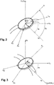
figure 2 est un dispositif horloger selon l'invention, dans une position quelconque - La
figure 3 est un dispositif horloger selon l'invention, dans une position corrélée à la position d'un astre qu'il pointe - la
figure 4 est un schéma bloc présentant les composants essentiels d'un dispositif horloger selon l'invention. - Comme dit précédemment, l'invention concerne un dispositif horloger adapté pour indiquer la position d'un astre. Dans l'exemple représenté sur les
figures 2 et 3 , le dispositif horloger est une montre bracelet, mais d'autres dispositifs horlogers peuvent être envisagés, tels qu'une montre gousset, un chronomètre, etc. - Les éléments du dispositif horloger essentiels à la mise en oeuvre de l'invention sont représentés schématiquement sur la
figure 4 : - un circuit 1 pour déterminer une heure courante,
- un circuit 2 pour déterminer une position géographique du dispositif horloger,
- un moyen 4 adapté pour déterminer la position de l'astre en fonction de l'heure courante et de la position géographique du dispositif horloger,
- un système d'affichage comprenant une première aiguille 8a, une deuxième aiguille 8b, et un moyen 8c adapté pour piloter les dites aiguilles en rotation dans un plan principal du dispositif horloger et afficher la position déterminée de l'astre.
- D'un point de vue pratique, dans l'exemple choisi d'une montre, tous les composants sont regroupés de manière classique dans une carrure à laquelle sont attachées les extrémités de deux brins d'un bracelet. La carrure est munie d'un fond et est fermée sur le dessus par une glace. Les deux aiguilles 8a, 8b se déplacent ici devant un cadran en forme de couronne qui porte à sa périphérie une graduation en heures et en minutes et/ou en degrés. Un repère cartésien lié au dispositif horloger est défini par deux axes XM , YM perpendiculaires entre eux et tous deux perpendiculaires à un axe ZM de rotation des aiguilles, les trois axes se coupant en un point O. Dans l'exemple représenté sur les figures, l'axe YM pointe en direction d'une graduation du cadran correspondant à 12H et l'axe XM pointe en direction d'une graduation du cadran correspondant à 3H. XM et YM définissent le plan principal du dispositif horloger.
- Le circuit 1 est réalisé selon un schéma classique dans le milieu horloger ; il comprend pour l'essentiel une base de temps pour produire un signal de fréquence standard et un circuit adapté pour déterminer l'heure courante à partir dudit signal de fréquence standard.
- Le circuit 2 de positionnement est également connu par ailleurs ; il s'agit par exemple d'une puce GPS (pour Global Positioning System) ou équivalent, apte à déterminer une position géographique sur la Terre à partir de signaux qu'elle reçoit d'un système de positionnement par satellites.
- Le système d'affichage 8 est dans le cadre de l'invention un système analogique comprenant au moins deux aiguilles 8a, 8b et un moyen de pilotage 8c de la position des aiguilles. Bien sûr, le système d'affichage peut également comprendre d'autres éléments tels que d'autres aiguilles, des cellules d'affichage électro-optique pour un affichage digital du type pseudo analogique par exemple du type pseudo analogique, etc. qui peuvent être utiles par ailleurs pour d'autres fonctions du dispositif horloger. Dans le cadre de l'invention, le système d'affichage est adapté pour :
- dans un premier mode de fonctionnement du dispositif horloger, afficher l'heure courante et
- dans un deuxième mode de fonctionnement du dispositif horloger, afficher la position déterminée de l'astre.
- Les moyens 4 comprennent essentiellement une mémoire de données 4a, une mémoire de programme 4b, et une unité de traitement 4c.
- La mémoire de données 4a peut comprendre notamment une carte du ciel mémorisée sous la forme d'une base de données comprenant une liste des astres (au moins un astre) susceptibles d'être pointés et, pour chaque astre identifié, des données représentatives de sa position dans le système solaire par rapport à la terre. D'un point de vue réalisation pratique, la mémoire de données peut être positionnée à proximité immédiate de l'unité de traitement 4c, dans un boîtier du dispositif horloger. En variante, tout ou partie de la mémoire de données peut être déportée sur un serveur de données distant. Les moyens 4 comprennent dans ce cas également des moyens d'émission et de réception appropriés pour accéder aux données du serveur de données. En variante encore, la mémoire de données 4a et la mémoire de programme 4b sont deux parties d'une même mémoire.
- La mémoire de programme 4b mémorise un programme exécutable par l'unité de traitement ; le dit programme comprend notamment une pluralité de lignes de codes appropriées pour la mise en oeuvre des fonctions de l'unité de traitement 4c et notamment, dans le cadre de l'invention, la fonction consistant à déterminer la position d'un astre sélectionné en fonction de l'heure courante et de la position géographique du dispositif horloger, et à faire afficher la position déterminée par ledit système d'affichage 8. De manière classique, l'unité de traitement met également en oeuvre une fonction consistant à faire afficher l'heure courante par le système d'affichage 8.
- L'unité de traitement 4c est reliée au circuit 1 pour recevoir des informations relatives à l'heure courante. Dans le cadre de l'invention, l'unité de traitement est également reliée au circuit 2 pour recevoir des informations relatives à la position géographique du dispositif horloger. L'unité de traitement peut encore être reliée à un moyen de sélection 10 pour recevoir une information relative à l'astre dont la position doit être affichée. En complément, l'unité de traitement peut être reliée à un serveur distant par toute liaison appropriée sans fil (WiFi, etc.) pour recevoir des données ou des instructions d'un serveur distant.
- Le deuxième mode de fonctionnement du dispositif horloger, spécifique à l'invention et permettant d'afficher la position déterminée de l'astre va maintenant être détaillé.
- De manière connue, dans un système de coordonnées cartésiennes (
figure 1 ) défini par un centre O et trois axes X0, Y0, Z0 perpendiculaires entre eux, la position d'un astre assimilé à un point A peut être définie par trois coordonnées (XA, YA, ZA) correspondant à la projection du point A respectivement sur les axes X0, Y0 et Z0. Plus communément dans le domaine de l'astronomie, les astres sont repérés dans un système de coordonnées horizontales centré sur un observateur au sol sur la Terre. Un système de coordonnées horizontales sépare le ciel en deux hémisphères : l'un situé au-dessus d'un point d'observation O et l'autre situé au-dessous. Le grand cercle séparant les deux hémisphères définit un plan horizontal, à partir duquel est établi un azimut αA et un angle d'élévation βA, qui constituent les deux principales coordonnées d'un astre dans ce système. Le plan horizontal passant par O est en pratique un plan parallèle à un plan tangent à la Terre et passant par le projeté du point O sur le sol Par souci de simplification, sur lafigure 1 , le dispositif horloger est positionné au point O, le plan horizontal est considéré comme étant le plan (X0, Y0) et le nord cardinal correspond à l'axe Y0. L'azimut αA est l'angle entre un cardinal (nord cardinal correspondant à l'axe Y0 sur lafigure 1 ) et la projection (droite (OAp)) de l'astre sélectionné sur le plan horizontal (X0, Y0). L'azimut αA est généralement exprimé en degrés, de 0° à 360° dans le sens horaire à partir du nord cardinal. L'angle d'élévation βA est l'angle vertical entre le plan horizontal et l'astre visé, exprimé en degré, dans le sens antihoraire à partir du plan vertical. - Dans un système de coordonnées horizontales ainsi défini, la position d'un astre A dépend de la position du centre O et du plan horizontal dans l'espace, qui dépendent eux-mêmes de la position géographique de l'observateur sur la Terre, et de la position de la Terre par rapport à l'astre dans le système solaire. La position de la Terre par rapport à l'astre dépend de l'heure courante, et de la date courante. La position géographique du dispositif horloger déterminée par le circuit 2 et l'heure et la date courante déterminée par le circuit 1, combinées aux informations mémorisées dans la mémoire de données 4a permettent ainsi à l'unité de traitement 4c de déterminer la position de l'astre dans un repère de coordonnées horizontales centré sur le dispositif horloger, selon des procédés de calcul certes complexes mais largement connus dans le domaine de l'astronomie.
- Le moyen de pilotage 8c des aiguilles d'affichage 8a, 8b est adapté pour déterminer l'axe cardinal Y0 (par ex. le nord cardinal) et pour orienter une première aiguille par rapport à l'axe cardinal Y0 selon l'azimut αA déterminé de l'astre A ; ladite aiguille est par exemple l'aiguille habituellement utilisée pour l'affichage des minutes de l'heure courante. Pour réaliser cette orientation, le moyen de pilotage des aiguilles peut comprendre par exemple un magnétomètre 2D apte à déterminer le nord cardinal Y0 et un moyen pour positionner et maintenir en position, dans le plan horizontal, la première aiguille par rapport au nord cardinal selon l'azimut αA de l'astre, la première aiguille étant par ailleurs laissée en rotation libre dans le plan principal du dispositif horloger. L'orientation de la première aiguille est indépendante du repère lié au dispositif horloger de sorte que cette orientation αA est maintenue quelle que soient les mouvements du dispositif horloger tant que le plan principal du dispositif horloger reste dans le plan horizontal. Ainsi, en positionnant le plan principal du dispositif horloger dans le plan horizontal et en regardant dans la direction indiquée par la pointe de la première aiguille, l'observateur regarde toujours dans la direction de l'azimut αA de l'astre sélectionné, même si le dispositif horloger est déplacé. La première aiguille se comporte ainsi comme l'aiguille d'une boussole qui serait attirée dans une direction formant un angle βA avec le nord cardinal.
- L'angle d'élévation βA de l'astre peut être affiché sur le dispositif horloger à l'aide la deuxième aiguille (par exemple l'aiguille habituellement utilisée pour l'affichage des heures de l'heure courante) de plusieurs façons.
- Selon un mode de réalisation, le moyen de pilotage des aiguilles est adapté pour positionner la deuxième aiguille, dans le plan principal (XM, YM) et par rapport à un axe de référence YM lié au dispositif horloger, selon un angle β égal à l'angle d'élévation βA de l'astre dans le repère de coordonnées horizontales centré sur le dispositif horloger d'un point de vue pratique, pour positionner la deuxième aiguille, le moyen de pilotage 8c entraîne en rotation la deuxième aiguille dans le plan principal de manière classique puis immobilise l'aiguille. Dans ce mode de réalisation, l'angle β est défini par rapport à l'axe de référence YM lié au dispositif horloger de sorte que, si le dispositif horloger est déplacé, l'angle β reste constant. Dans ce mode de réalisation, pour visualiser l'astre, l'observateur peut utiliser le dispositif horloger de la manière suivante. Le dispositif horloger est orienté dans le plan horizontal de sorte que la première aiguille (orientée selon l'azimut de l'astre), libre en rotation, soit alignée selon l'axe de référence YM du dispositif horloger (correspondant au repère 12H dans l'exemple). Ensuite, le dispositif horloger est tourné selon l'axe de référence YM en maintenant l'axe de référence YM fixe dans le plan horizontal de sorte que le plan formé par l'axe YM et la deuxième aiguille soit vertical. L'observateur peut alors visualiser l'astre sélectionné en regardant dans la direction pointée par l'extrémité de la deuxième aiguille.
- Selon un autre mode de réalisation, le moyen de pilotage des aiguilles est adapté pour orienter la deuxième aiguille par rapport au plan horizontal selon l'angle d'élévation βA de l'astre dans le repère de coordonnées horizontales centré sur le dispositif horloger.
- Pour réaliser cette orientation, le moyen de pilotage des aiguilles peut comprendre par exemple un magnétomètre 3D apte à déterminer le nord cardinal et un moyen pour :
- positionner et maintenir en position, dans le plan horizontal, la première aiguille par rapport au nord cardinal selon un angle égal à l'azimut αA de l'astre,
- positionner et maintenir en position, dans un plan vertical, la deuxième aiguille par rapport au plan horizontal selon un angle égal à l'angle d'élévation βA de l'astre.
- La première aiguille et la deuxième aiguille sont par ailleurs laissées en rotation libre dans le plan principal du dispositif horloger. Comme pour la première aiguille, l'orientation de la deuxième aiguille est ici indépendante du repère lié au dispositif horloger de sorte que cette orientation βA est maintenue quelle que soit les mouvements du dispositif horloger dans un plan vertical. Les aiguilles se comportent ainsi comme l'aiguille d'une boussole qui serait attirée dans la direction de l'astre.
- Dans ce mode de réalisation, pour visualiser l'astre, l'observateur peut utiliser le dispositif horloger de la manière suivante. Le dispositif horloger est orienté dans le plan horizontal de sorte que la première aiguille (orientée selon l'azimut de l'astre), libre en rotation, soit alignée selon l'axe de référence YM du dispositif horloger (correspondant au repère 12H dans l'exemple). Ensuite, le dispositif horloger est tourné selon l'axe de référence YM en maintenant l'axe de référence YM fixe dans le plan horizontal de sorte que le plan formé par l'axe YM et la deuxième aiguille soit vertical. Enfin, le dispositif horloger est orienté dans le plan vertical de sorte que la deuxième aiguille (orientée selon l'angle d'élévation de l'astre), libre en rotation, soit également alignée selon l'axe de référence YM du dispositif horloger. Alors, lorsque les deux aiguilles sont alignées avec l'axe de référence YM, l'observateur peut visualiser l'astre sélectionné en regardant dans la direction pointée par l'extrémité des deux aiguilles.
- Selon une variante on pourra encore envisager de valider l'orientation en azimut et en élévation au moyen d'un signal sonore ou d'une vibration qui se déclenche lorsque l'azimut et l'élévation pour l'observation de l'astre déterminé sont atteints.
- Le dispositif horloger selon l'invention peut encore comprendre un moyen de sélection 10 d'un mode de fonctionnement du dispositif horloger. Le moyen 10 est dans un exemple assurément non limitatif une tige de commande rotative et à plusieurs positions axiales, chaque position axiale correspondant à un mode de fonctionnement du dispositif horloger.
- Le dispositif horloger selon l'invention peut encore comprendre un moyen de sélection d'un astre parmi une pluralité d'astres enregistrés dans la mémoire 4a. Dans un exemple assurément non limitatif, le moyen de sélection d'un astre peut comprendre :
- un élément d'affichage digital,
- un moyen d'incrémentation permettant à l'utilisateur de faire afficher sur l'élément d'affichage digital successivement les astres d'une liste contenue dans la mémoire de données et
- un moyen de validation tel qu'un bouton de commande que l'utilisateur peut actionner pour sélectionner l'astre affiché.
- Selon un mode de réalisation, le moyen d'incrémentation peut être un bouton de commande, des appuis successifs sur le bouton permettant de faire défiler les astres de la liste. En variante, le moyen d'incrémentation peut être la tige de commande rotative dans une position axiale associée au deuxième mode de fonctionnement du dispositif horloger (affichage de la position d'un astre), une rotation de la tige entraînant un défilement de la liste des astres.
- On pourra encore prévoir selon une variante avantageuse que lorsque l'astre sélectionné par l'utilisateur n'est pas observable à partir de l'endroit où se trouve ce dernier, des moyens soit prévus pour informer l'utilisateur de cet état de situation, par exemple en amenant par une commande appropriée du moteur d'entrainement des aiguilles, ces dernières dans une position caractéristique.
- Selon une autre variante de réalisation, on pourrait envisager de sélectionner l'astre à observer sur un terminal déporté par rapport à la montre, tel qu'un téléphone portable, une tablette ou analogue, et d'envoyer par communication sans fil, ou informatique, ou autre, la sélection correspondante. Il va de soi que dans ce cas la montre comprend une antenne et/ou une prise ainsi qu'un circuit récepteur approprié.
-
- 1. circuit pour déterminer une heure courante
- 2. circuit pour déterminer une position géographique
- 4. moyen pour déterminer la position d'un astre
- 4a mémoire de données
- 4b mémoire de programme
- 4c unité de traitement
- 8 système d'affichage
- 8a, 8b : deux aiguilles
- 8c moyen de pilotage des aiguilles
- 10. moyen de sélection d'un mode de fonctionnement
Claims (8)
- Dispositif horloger adapté pour indiquer la position d'un astre, caractérisé en ce qu'il comprend :- un circuit (1) pour déterminer une heure courante,- un circuit (2) pour déterminer une position géographique du dispositif horloger,- un moyen (4) adapté pour déterminer la position de l'astre en fonction de l'heure courante et de la position géographique du dispositif horloger,- un système d'affichage comprenant une première aiguille (8a), une deuxième aiguille (8b), et un moyen (8c) adapté pour piloter les dites aiguilles en rotation dans un plan principal (XM, YM) du dispositif horloger et afficher la position déterminée de l'astre.
- Dispositif horloger selon la revendication 1, caractérisée en ce que le système d'affichage (6) est adapté pour :- dans un premier mode de fonctionnement du dispositif horloger, afficher l'heure courante et,- dans un deuxième mode de fonctionnement du dispositif horloger, afficher la position déterminée de l'astre.
- Dispositif horloger selon l'une des revendications 1 ou 2 dans lequel la position de l'astre est déterminée dans un repère de coordonnées horizontales centré sur le dispositif horloger par un azimut (αA) et un angle d'élévation (βA), repère défini par un plan horizontal (X0, Y0) et un axe vertical (Z0), le moyen de pilotage des aiguilles étant adapté pour déterminer un axe cardinal (Y0) dans le plan horizontal et orienter une première aiguille par rapport à l'axe cardinal selon l'azimut déterminé de l'astre.
- Dispositif horloger selon la revendication 3, dans lequel le moyen de pilotage des aiguilles est adapté pour positionner une deuxième aiguille, par rapport à un axe de référence (YM) lié au dispositif horloger, selon un angle β égal à l'angle d'élévation βA de l'astre.
- Dispositif horloger selon la revendication 3, dans lequel le moyen de pilotage des aiguilles est adapté pour orienter la deuxième aiguille par rapport au plan horizontal selon l'angle d'élévation βA de déterminé de l'astre.
- Dispositif selon l'une des revendications 1 à 5 comprenant également un moyen de sélection d'un astre parmi une pluralité d'astres.
- Dispositif horloger selon l'une des revendications 2 à 6, comprenant également un moyen de sélection (10) d'un mode de fonctionnement du dispositif horloger.
- Dispositif horloger selon l'une des revendications précédentes, de type montre-bracelet.
Priority Applications (4)
| Application Number | Priority Date | Filing Date | Title |
|---|---|---|---|
| EP17190158.0A EP3454140B1 (fr) | 2017-09-08 | 2017-09-08 | Dispositif horloger astronomique |
| US16/104,987 US11119445B2 (en) | 2017-09-08 | 2018-08-20 | Astronomical horological device |
| JP2018164236A JP6743100B2 (ja) | 2017-09-08 | 2018-09-03 | 天体時計デバイス |
| CN201811031224.3A CN109471348B (zh) | 2017-09-08 | 2018-09-05 | 天文钟表装置 |
Applications Claiming Priority (1)
| Application Number | Priority Date | Filing Date | Title |
|---|---|---|---|
| EP17190158.0A EP3454140B1 (fr) | 2017-09-08 | 2017-09-08 | Dispositif horloger astronomique |
Publications (2)
| Publication Number | Publication Date |
|---|---|
| EP3454140A1 true EP3454140A1 (fr) | 2019-03-13 |
| EP3454140B1 EP3454140B1 (fr) | 2020-02-26 |
Family
ID=59829292
Family Applications (1)
| Application Number | Title | Priority Date | Filing Date |
|---|---|---|---|
| EP17190158.0A Active EP3454140B1 (fr) | 2017-09-08 | 2017-09-08 | Dispositif horloger astronomique |
Country Status (4)
| Country | Link |
|---|---|
| US (1) | US11119445B2 (fr) |
| EP (1) | EP3454140B1 (fr) |
| JP (1) | JP6743100B2 (fr) |
| CN (1) | CN109471348B (fr) |
Families Citing this family (1)
| Publication number | Priority date | Publication date | Assignee | Title |
|---|---|---|---|---|
| US11537093B2 (en) * | 2019-03-08 | 2022-12-27 | Citizen Watch Co., Ltd. | Mobile device and mobile device system |
Citations (6)
| Publication number | Priority date | Publication date | Assignee | Title |
|---|---|---|---|---|
| JPH052064A (ja) * | 1990-12-26 | 1993-01-08 | Marantz Japan Inc | 衛星航法受信装置 |
| JPH10332376A (ja) * | 1997-05-27 | 1998-12-18 | Mitsuaki Arita | 方位指針付き時計 |
| EP0949549A1 (fr) | 1998-04-09 | 1999-10-13 | Asulab S.A. | Montre astronomique |
| WO2005111743A1 (fr) * | 2004-05-13 | 2005-11-24 | Gangming Yan | Nouvel horloge astronomique planetaire |
| KR20060112770A (ko) * | 2005-04-28 | 2006-11-02 | 어윤형 | 자연현상을 반영한 천체시계 |
| US20130116967A1 (en) * | 2011-11-09 | 2013-05-09 | Lonestar Inventions, L.P. | Solar timer using gps technology |
Family Cites Families (8)
| Publication number | Priority date | Publication date | Assignee | Title |
|---|---|---|---|---|
| JPH0827592B2 (ja) * | 1993-10-21 | 1996-03-21 | 株式会社ハドソン | 自然環境案内装置 |
| CN2256110Y (zh) * | 1995-10-25 | 1997-06-11 | 汪仁虎 | 时空计 |
| EP1498790B1 (fr) * | 2003-07-14 | 2008-05-14 | Asulab S.A. | Montre astronomique |
| CN100533065C (zh) * | 2006-05-31 | 2009-08-26 | 哈尔滨工业大学 | 基于多天体路标的星际巡航自主导航方法 |
| CN200944152Y (zh) * | 2006-07-04 | 2007-09-05 | 苏州信达光电科技有限公司 | 自动跟踪天体目标的经纬仪托架式望远镜系统 |
| EP3183712B1 (fr) | 2014-08-18 | 2020-07-22 | Google LLC | Détermination d'orientation d'imagerie par compas |
| CN105141825B (zh) * | 2015-06-23 | 2018-08-21 | 努比亚技术有限公司 | 一种天体拍摄方法及装置 |
| CN106767824B (zh) * | 2016-12-14 | 2020-05-12 | 中国人民解放军63921部队 | 一种计算双探测器在地外天体表面相对位置的方法 |
-
2017
- 2017-09-08 EP EP17190158.0A patent/EP3454140B1/fr active Active
-
2018
- 2018-08-20 US US16/104,987 patent/US11119445B2/en active Active
- 2018-09-03 JP JP2018164236A patent/JP6743100B2/ja active Active
- 2018-09-05 CN CN201811031224.3A patent/CN109471348B/zh active Active
Patent Citations (6)
| Publication number | Priority date | Publication date | Assignee | Title |
|---|---|---|---|---|
| JPH052064A (ja) * | 1990-12-26 | 1993-01-08 | Marantz Japan Inc | 衛星航法受信装置 |
| JPH10332376A (ja) * | 1997-05-27 | 1998-12-18 | Mitsuaki Arita | 方位指針付き時計 |
| EP0949549A1 (fr) | 1998-04-09 | 1999-10-13 | Asulab S.A. | Montre astronomique |
| WO2005111743A1 (fr) * | 2004-05-13 | 2005-11-24 | Gangming Yan | Nouvel horloge astronomique planetaire |
| KR20060112770A (ko) * | 2005-04-28 | 2006-11-02 | 어윤형 | 자연현상을 반영한 천체시계 |
| US20130116967A1 (en) * | 2011-11-09 | 2013-05-09 | Lonestar Inventions, L.P. | Solar timer using gps technology |
Also Published As
| Publication number | Publication date |
|---|---|
| JP6743100B2 (ja) | 2020-08-19 |
| JP2019049548A (ja) | 2019-03-28 |
| US20190079455A1 (en) | 2019-03-14 |
| CN109471348A (zh) | 2019-03-15 |
| CN109471348B (zh) | 2021-11-23 |
| EP3454140B1 (fr) | 2020-02-26 |
| US11119445B2 (en) | 2021-09-14 |
Similar Documents
| Publication | Publication Date | Title |
|---|---|---|
| EP1701229B1 (fr) | Montre électronique ayant une fonction de boussole | |
| EP3379348B1 (fr) | Affichage de phase de lune universel | |
| FR3070509B1 (fr) | Equipement electronique d’horlogerie indiquant l’heure et l’azimut du soleil au moyen d’une unique aiguille indicatrice | |
| EP1498790B1 (fr) | Montre astronomique | |
| CH688949GA3 (fr) | Montre comprenant un dispositif d'indication d'un lieu géographique prédéterminé. | |
| EP3096191A1 (fr) | Dispositif intelligent de remontage de montres | |
| CH691084A5 (fr) | Pièce d'horlogerie comprenant un récepteur GPS, destinée à indiquer la direction d'un endroit "but". | |
| EP1724604B1 (fr) | Dispositif et procédé pour déterminer la position avec un récepteur GPS et une boussole | |
| EP1412701A2 (fr) | Systeme de mesure et de localisation utilisant les bases trois et neuf et applications correspondantes | |
| EP3454140B1 (fr) | Dispositif horloger astronomique | |
| EP0660205B1 (fr) | Procédé pour faire le point et pièce d'horlogerie destinée à mettre en oeuvre ce procédé | |
| CH714127A2 (fr) | Dispositif horloger astronomique. | |
| EP0476425A1 (fr) | Pièce d'horlogerie pouvant être portée de différentes manières | |
| EP0871096B1 (fr) | Pièce d'horlogerie comprenant un récepteur GPS, destinée à indiquer la direction d'un endroit "but" | |
| CH712096A2 (fr) | Mouvement d'horlogerie à affichage d'informations astronomiques. | |
| US1201895A (en) | Apparatus for converting sidereal time to mean solar time and vice versa. | |
| EP2923243B1 (fr) | Montre-bracelet ou montre de poche destinée à indiquer des informations astrales | |
| EP3217231A1 (fr) | Systeme de navigation a affichage deporté | |
| FR3005360A1 (fr) | Moyen d'affichage de l'heure dans plusieurs fuseaux horaires et montre ou dispositif electronique comprenant un tel moyen d'affichage | |
| CH698599B1 (fr) | Dispositif électronique portable à récepteur de signaux radiofréquences, et procédé de détermination de position d'un tel dispositif. | |
| CH715167B1 (fr) | Dispositif d'affichage astronomique. | |
| CH712202B1 (fr) | Système de navigation à affichage déporté. | |
| FR3016692A1 (fr) | Dispositif d'aide a l'orientation | |
| BE421338A (fr) | ||
| CH707237A1 (fr) | Montre-bracelet ou montre de poche destinée à indiquer des informations astrales. |
Legal Events
| Date | Code | Title | Description |
|---|---|---|---|
| PUAI | Public reference made under article 153(3) epc to a published international application that has entered the european phase |
Free format text: ORIGINAL CODE: 0009012 |
|
| STAA | Information on the status of an ep patent application or granted ep patent |
Free format text: STATUS: THE APPLICATION HAS BEEN PUBLISHED |
|
| AK | Designated contracting states |
Kind code of ref document: A1 Designated state(s): AL AT BE BG CH CY CZ DE DK EE ES FI FR GB GR HR HU IE IS IT LI LT LU LV MC MK MT NL NO PL PT RO RS SE SI SK SM TR |
|
| AX | Request for extension of the european patent |
Extension state: BA ME |
|
| STAA | Information on the status of an ep patent application or granted ep patent |
Free format text: STATUS: REQUEST FOR EXAMINATION WAS MADE |
|
| GRAP | Despatch of communication of intention to grant a patent |
Free format text: ORIGINAL CODE: EPIDOSNIGR1 |
|
| STAA | Information on the status of an ep patent application or granted ep patent |
Free format text: STATUS: GRANT OF PATENT IS INTENDED |
|
| 17P | Request for examination filed |
Effective date: 20190913 |
|
| RBV | Designated contracting states (corrected) |
Designated state(s): AL AT BE BG CH CY CZ DE DK EE ES FI FR GB GR HR HU IE IS IT LI LT LU LV MC MK MT NL NO PL PT RO RS SE SI SK SM TR |
|
| INTG | Intention to grant announced |
Effective date: 20191022 |
|
| RIN1 | Information on inventor provided before grant (corrected) |
Inventor name: PETERS, JEAN-BERNARD |
|
| GRAS | Grant fee paid |
Free format text: ORIGINAL CODE: EPIDOSNIGR3 |
|
| GRAA | (expected) grant |
Free format text: ORIGINAL CODE: 0009210 |
|
| STAA | Information on the status of an ep patent application or granted ep patent |
Free format text: STATUS: THE PATENT HAS BEEN GRANTED |
|
| AK | Designated contracting states |
Kind code of ref document: B1 Designated state(s): AL AT BE BG CH CY CZ DE DK EE ES FI FR GB GR HR HU IE IS IT LI LT LU LV MC MK MT NL NO PL PT RO RS SE SI SK SM TR |
|
| REG | Reference to a national code |
Ref country code: GB Ref legal event code: FG4D Free format text: NOT ENGLISH |
|
| REG | Reference to a national code |
Ref country code: CH Ref legal event code: EP |
|
| REG | Reference to a national code |
Ref country code: DE Ref legal event code: R096 Ref document number: 602017012181 Country of ref document: DE |
|
| REG | Reference to a national code |
Ref country code: CH Ref legal event code: NV Representative=s name: ICB INGENIEURS CONSEILS EN BREVETS SA, CH |
|
| REG | Reference to a national code |
Ref country code: AT Ref legal event code: REF Ref document number: 1238394 Country of ref document: AT Kind code of ref document: T Effective date: 20200315 |
|
| REG | Reference to a national code |
Ref country code: IE Ref legal event code: FG4D Free format text: LANGUAGE OF EP DOCUMENT: FRENCH |
|
| PG25 | Lapsed in a contracting state [announced via postgrant information from national office to epo] |
Ref country code: NO Free format text: LAPSE BECAUSE OF FAILURE TO SUBMIT A TRANSLATION OF THE DESCRIPTION OR TO PAY THE FEE WITHIN THE PRESCRIBED TIME-LIMIT Effective date: 20200526 Ref country code: RS Free format text: LAPSE BECAUSE OF FAILURE TO SUBMIT A TRANSLATION OF THE DESCRIPTION OR TO PAY THE FEE WITHIN THE PRESCRIBED TIME-LIMIT Effective date: 20200226 Ref country code: FI Free format text: LAPSE BECAUSE OF FAILURE TO SUBMIT A TRANSLATION OF THE DESCRIPTION OR TO PAY THE FEE WITHIN THE PRESCRIBED TIME-LIMIT Effective date: 20200226 |
|
| REG | Reference to a national code |
Ref country code: NL Ref legal event code: MP Effective date: 20200226 |
|
| REG | Reference to a national code |
Ref country code: LT Ref legal event code: MG4D |
|
| PG25 | Lapsed in a contracting state [announced via postgrant information from national office to epo] |
Ref country code: IS Free format text: LAPSE BECAUSE OF FAILURE TO SUBMIT A TRANSLATION OF THE DESCRIPTION OR TO PAY THE FEE WITHIN THE PRESCRIBED TIME-LIMIT Effective date: 20200626 Ref country code: HR Free format text: LAPSE BECAUSE OF FAILURE TO SUBMIT A TRANSLATION OF THE DESCRIPTION OR TO PAY THE FEE WITHIN THE PRESCRIBED TIME-LIMIT Effective date: 20200226 Ref country code: GR Free format text: LAPSE BECAUSE OF FAILURE TO SUBMIT A TRANSLATION OF THE DESCRIPTION OR TO PAY THE FEE WITHIN THE PRESCRIBED TIME-LIMIT Effective date: 20200527 Ref country code: BG Free format text: LAPSE BECAUSE OF FAILURE TO SUBMIT A TRANSLATION OF THE DESCRIPTION OR TO PAY THE FEE WITHIN THE PRESCRIBED TIME-LIMIT Effective date: 20200526 Ref country code: LV Free format text: LAPSE BECAUSE OF FAILURE TO SUBMIT A TRANSLATION OF THE DESCRIPTION OR TO PAY THE FEE WITHIN THE PRESCRIBED TIME-LIMIT Effective date: 20200226 Ref country code: SE Free format text: LAPSE BECAUSE OF FAILURE TO SUBMIT A TRANSLATION OF THE DESCRIPTION OR TO PAY THE FEE WITHIN THE PRESCRIBED TIME-LIMIT Effective date: 20200226 |
|
| PG25 | Lapsed in a contracting state [announced via postgrant information from national office to epo] |
Ref country code: NL Free format text: LAPSE BECAUSE OF FAILURE TO SUBMIT A TRANSLATION OF THE DESCRIPTION OR TO PAY THE FEE WITHIN THE PRESCRIBED TIME-LIMIT Effective date: 20200226 |
|
| PG25 | Lapsed in a contracting state [announced via postgrant information from national office to epo] |
Ref country code: DK Free format text: LAPSE BECAUSE OF FAILURE TO SUBMIT A TRANSLATION OF THE DESCRIPTION OR TO PAY THE FEE WITHIN THE PRESCRIBED TIME-LIMIT Effective date: 20200226 Ref country code: PT Free format text: LAPSE BECAUSE OF FAILURE TO SUBMIT A TRANSLATION OF THE DESCRIPTION OR TO PAY THE FEE WITHIN THE PRESCRIBED TIME-LIMIT Effective date: 20200719 Ref country code: LT Free format text: LAPSE BECAUSE OF FAILURE TO SUBMIT A TRANSLATION OF THE DESCRIPTION OR TO PAY THE FEE WITHIN THE PRESCRIBED TIME-LIMIT Effective date: 20200226 Ref country code: ES Free format text: LAPSE BECAUSE OF FAILURE TO SUBMIT A TRANSLATION OF THE DESCRIPTION OR TO PAY THE FEE WITHIN THE PRESCRIBED TIME-LIMIT Effective date: 20200226 Ref country code: SM Free format text: LAPSE BECAUSE OF FAILURE TO SUBMIT A TRANSLATION OF THE DESCRIPTION OR TO PAY THE FEE WITHIN THE PRESCRIBED TIME-LIMIT Effective date: 20200226 Ref country code: EE Free format text: LAPSE BECAUSE OF FAILURE TO SUBMIT A TRANSLATION OF THE DESCRIPTION OR TO PAY THE FEE WITHIN THE PRESCRIBED TIME-LIMIT Effective date: 20200226 Ref country code: CZ Free format text: LAPSE BECAUSE OF FAILURE TO SUBMIT A TRANSLATION OF THE DESCRIPTION OR TO PAY THE FEE WITHIN THE PRESCRIBED TIME-LIMIT Effective date: 20200226 Ref country code: RO Free format text: LAPSE BECAUSE OF FAILURE TO SUBMIT A TRANSLATION OF THE DESCRIPTION OR TO PAY THE FEE WITHIN THE PRESCRIBED TIME-LIMIT Effective date: 20200226 Ref country code: SK Free format text: LAPSE BECAUSE OF FAILURE TO SUBMIT A TRANSLATION OF THE DESCRIPTION OR TO PAY THE FEE WITHIN THE PRESCRIBED TIME-LIMIT Effective date: 20200226 |
|
| REG | Reference to a national code |
Ref country code: AT Ref legal event code: MK05 Ref document number: 1238394 Country of ref document: AT Kind code of ref document: T Effective date: 20200226 |
|
| REG | Reference to a national code |
Ref country code: DE Ref legal event code: R097 Ref document number: 602017012181 Country of ref document: DE |
|
| PLBE | No opposition filed within time limit |
Free format text: ORIGINAL CODE: 0009261 |
|
| STAA | Information on the status of an ep patent application or granted ep patent |
Free format text: STATUS: NO OPPOSITION FILED WITHIN TIME LIMIT |
|
| PG25 | Lapsed in a contracting state [announced via postgrant information from national office to epo] |
Ref country code: IT Free format text: LAPSE BECAUSE OF FAILURE TO SUBMIT A TRANSLATION OF THE DESCRIPTION OR TO PAY THE FEE WITHIN THE PRESCRIBED TIME-LIMIT Effective date: 20200226 Ref country code: AT Free format text: LAPSE BECAUSE OF FAILURE TO SUBMIT A TRANSLATION OF THE DESCRIPTION OR TO PAY THE FEE WITHIN THE PRESCRIBED TIME-LIMIT Effective date: 20200226 |
|
| 26N | No opposition filed |
Effective date: 20201127 |
|
| PG25 | Lapsed in a contracting state [announced via postgrant information from national office to epo] |
Ref country code: PL Free format text: LAPSE BECAUSE OF FAILURE TO SUBMIT A TRANSLATION OF THE DESCRIPTION OR TO PAY THE FEE WITHIN THE PRESCRIBED TIME-LIMIT Effective date: 20200226 Ref country code: SI Free format text: LAPSE BECAUSE OF FAILURE TO SUBMIT A TRANSLATION OF THE DESCRIPTION OR TO PAY THE FEE WITHIN THE PRESCRIBED TIME-LIMIT Effective date: 20200226 |
|
| REG | Reference to a national code |
Ref country code: BE Ref legal event code: MM Effective date: 20200930 |
|
| PG25 | Lapsed in a contracting state [announced via postgrant information from national office to epo] |
Ref country code: LU Free format text: LAPSE BECAUSE OF NON-PAYMENT OF DUE FEES Effective date: 20200908 |
|
| PG25 | Lapsed in a contracting state [announced via postgrant information from national office to epo] |
Ref country code: IE Free format text: LAPSE BECAUSE OF NON-PAYMENT OF DUE FEES Effective date: 20200908 Ref country code: BE Free format text: LAPSE BECAUSE OF NON-PAYMENT OF DUE FEES Effective date: 20200930 |
|
| PG25 | Lapsed in a contracting state [announced via postgrant information from national office to epo] |
Ref country code: TR Free format text: LAPSE BECAUSE OF FAILURE TO SUBMIT A TRANSLATION OF THE DESCRIPTION OR TO PAY THE FEE WITHIN THE PRESCRIBED TIME-LIMIT Effective date: 20200226 Ref country code: MT Free format text: LAPSE BECAUSE OF FAILURE TO SUBMIT A TRANSLATION OF THE DESCRIPTION OR TO PAY THE FEE WITHIN THE PRESCRIBED TIME-LIMIT Effective date: 20200226 Ref country code: CY Free format text: LAPSE BECAUSE OF FAILURE TO SUBMIT A TRANSLATION OF THE DESCRIPTION OR TO PAY THE FEE WITHIN THE PRESCRIBED TIME-LIMIT Effective date: 20200226 |
|
| PG25 | Lapsed in a contracting state [announced via postgrant information from national office to epo] |
Ref country code: MK Free format text: LAPSE BECAUSE OF FAILURE TO SUBMIT A TRANSLATION OF THE DESCRIPTION OR TO PAY THE FEE WITHIN THE PRESCRIBED TIME-LIMIT Effective date: 20200226 Ref country code: MC Free format text: LAPSE BECAUSE OF FAILURE TO SUBMIT A TRANSLATION OF THE DESCRIPTION OR TO PAY THE FEE WITHIN THE PRESCRIBED TIME-LIMIT Effective date: 20200226 Ref country code: AL Free format text: LAPSE BECAUSE OF FAILURE TO SUBMIT A TRANSLATION OF THE DESCRIPTION OR TO PAY THE FEE WITHIN THE PRESCRIBED TIME-LIMIT Effective date: 20200226 |
|
| P01 | Opt-out of the competence of the unified patent court (upc) registered |
Effective date: 20230701 |
|
| REG | Reference to a national code |
Ref country code: CH Ref legal event code: U11 Free format text: ST27 STATUS EVENT CODE: U-0-0-U10-U11 (AS PROVIDED BY THE NATIONAL OFFICE) Effective date: 20251001 |
|
| PGFP | Annual fee paid to national office [announced via postgrant information from national office to epo] |
Ref country code: DE Payment date: 20250820 Year of fee payment: 9 |
|
| PGFP | Annual fee paid to national office [announced via postgrant information from national office to epo] |
Ref country code: GB Payment date: 20250820 Year of fee payment: 9 |
|
| PGFP | Annual fee paid to national office [announced via postgrant information from national office to epo] |
Ref country code: FR Payment date: 20250820 Year of fee payment: 9 |
|
| PGFP | Annual fee paid to national office [announced via postgrant information from national office to epo] |
Ref country code: CH Payment date: 20251001 Year of fee payment: 9 |