EP3454111B1 - Mach-zehnder-modulator mit regelvorrichtung zur arbeitspunktregelung sowie verfahren zur arbeitspunktregelung - Google Patents
Mach-zehnder-modulator mit regelvorrichtung zur arbeitspunktregelung sowie verfahren zur arbeitspunktregelung Download PDFInfo
- Publication number
- EP3454111B1 EP3454111B1 EP18189959.2A EP18189959A EP3454111B1 EP 3454111 B1 EP3454111 B1 EP 3454111B1 EP 18189959 A EP18189959 A EP 18189959A EP 3454111 B1 EP3454111 B1 EP 3454111B1
- Authority
- EP
- European Patent Office
- Prior art keywords
- optical
- control
- signal
- mach
- zehnder modulator
- Prior art date
- Legal status (The legal status is an assumption and is not a legal conclusion. Google has not performed a legal analysis and makes no representation as to the accuracy of the status listed.)
- Active
Links
- 238000000034 method Methods 0.000 title claims description 7
- 230000003287 optical effect Effects 0.000 claims description 402
- 238000005259 measurement Methods 0.000 claims description 40
- 230000005540 biological transmission Effects 0.000 claims description 14
- 239000004020 conductor Substances 0.000 description 9
- 230000001276 controlling effect Effects 0.000 description 8
- 230000010363 phase shift Effects 0.000 description 6
- 230000007613 environmental effect Effects 0.000 description 5
- 230000000704 physical effect Effects 0.000 description 5
- 230000006735 deficit Effects 0.000 description 4
- 239000003365 glass fiber Substances 0.000 description 4
- 230000001105 regulatory effect Effects 0.000 description 4
- XUIMIQQOPSSXEZ-UHFFFAOYSA-N Silicon Chemical compound [Si] XUIMIQQOPSSXEZ-UHFFFAOYSA-N 0.000 description 3
- 230000001066 destructive effect Effects 0.000 description 3
- 229910052710 silicon Inorganic materials 0.000 description 3
- 239000010703 silicon Substances 0.000 description 3
- 230000033228 biological regulation Effects 0.000 description 2
- 230000002950 deficient Effects 0.000 description 2
- 238000001514 detection method Methods 0.000 description 2
- 238000005516 engineering process Methods 0.000 description 2
- 230000010354 integration Effects 0.000 description 2
- GQYHUHYESMUTHG-UHFFFAOYSA-N lithium niobate Chemical compound [Li+].[O-][Nb](=O)=O GQYHUHYESMUTHG-UHFFFAOYSA-N 0.000 description 2
- 229910052581 Si3N4 Inorganic materials 0.000 description 1
- 230000015572 biosynthetic process Effects 0.000 description 1
- 238000004891 communication Methods 0.000 description 1
- 238000012937 correction Methods 0.000 description 1
- 230000007423 decrease Effects 0.000 description 1
- 230000001419 dependent effect Effects 0.000 description 1
- 238000009795 derivation Methods 0.000 description 1
- 238000011161 development Methods 0.000 description 1
- 230000000694 effects Effects 0.000 description 1
- 230000005672 electromagnetic field Effects 0.000 description 1
- 238000004519 manufacturing process Methods 0.000 description 1
- 239000000463 material Substances 0.000 description 1
- 238000012544 monitoring process Methods 0.000 description 1
- 238000013021 overheating Methods 0.000 description 1
- 230000000750 progressive effect Effects 0.000 description 1
- 230000001902 propagating effect Effects 0.000 description 1
- HQVNEWCFYHHQES-UHFFFAOYSA-N silicon nitride Chemical compound N12[Si]34N5[Si]62N3[Si]51N64 HQVNEWCFYHHQES-UHFFFAOYSA-N 0.000 description 1
Images


Classifications
-
- G—PHYSICS
- G02—OPTICS
- G02F—OPTICAL DEVICES OR ARRANGEMENTS FOR THE CONTROL OF LIGHT BY MODIFICATION OF THE OPTICAL PROPERTIES OF THE MEDIA OF THE ELEMENTS INVOLVED THEREIN; NON-LINEAR OPTICS; FREQUENCY-CHANGING OF LIGHT; OPTICAL LOGIC ELEMENTS; OPTICAL ANALOGUE/DIGITAL CONVERTERS
- G02F1/00—Devices or arrangements for the control of the intensity, colour, phase, polarisation or direction of light arriving from an independent light source, e.g. switching, gating or modulating; Non-linear optics
- G02F1/01—Devices or arrangements for the control of the intensity, colour, phase, polarisation or direction of light arriving from an independent light source, e.g. switching, gating or modulating; Non-linear optics for the control of the intensity, phase, polarisation or colour
- G02F1/21—Devices or arrangements for the control of the intensity, colour, phase, polarisation or direction of light arriving from an independent light source, e.g. switching, gating or modulating; Non-linear optics for the control of the intensity, phase, polarisation or colour by interference
- G02F1/225—Devices or arrangements for the control of the intensity, colour, phase, polarisation or direction of light arriving from an independent light source, e.g. switching, gating or modulating; Non-linear optics for the control of the intensity, phase, polarisation or colour by interference in an optical waveguide structure
-
- G—PHYSICS
- G02—OPTICS
- G02F—OPTICAL DEVICES OR ARRANGEMENTS FOR THE CONTROL OF LIGHT BY MODIFICATION OF THE OPTICAL PROPERTIES OF THE MEDIA OF THE ELEMENTS INVOLVED THEREIN; NON-LINEAR OPTICS; FREQUENCY-CHANGING OF LIGHT; OPTICAL LOGIC ELEMENTS; OPTICAL ANALOGUE/DIGITAL CONVERTERS
- G02F1/00—Devices or arrangements for the control of the intensity, colour, phase, polarisation or direction of light arriving from an independent light source, e.g. switching, gating or modulating; Non-linear optics
- G02F1/01—Devices or arrangements for the control of the intensity, colour, phase, polarisation or direction of light arriving from an independent light source, e.g. switching, gating or modulating; Non-linear optics for the control of the intensity, phase, polarisation or colour
- G02F1/0121—Operation of devices; Circuit arrangements, not otherwise provided for in this subclass
- G02F1/0123—Circuits for the control or stabilisation of the bias voltage, e.g. automatic bias control [ABC] feedback loops
-
- G—PHYSICS
- G02—OPTICS
- G02F—OPTICAL DEVICES OR ARRANGEMENTS FOR THE CONTROL OF LIGHT BY MODIFICATION OF THE OPTICAL PROPERTIES OF THE MEDIA OF THE ELEMENTS INVOLVED THEREIN; NON-LINEAR OPTICS; FREQUENCY-CHANGING OF LIGHT; OPTICAL LOGIC ELEMENTS; OPTICAL ANALOGUE/DIGITAL CONVERTERS
- G02F1/00—Devices or arrangements for the control of the intensity, colour, phase, polarisation or direction of light arriving from an independent light source, e.g. switching, gating or modulating; Non-linear optics
- G02F1/01—Devices or arrangements for the control of the intensity, colour, phase, polarisation or direction of light arriving from an independent light source, e.g. switching, gating or modulating; Non-linear optics for the control of the intensity, phase, polarisation or colour
- G02F1/21—Devices or arrangements for the control of the intensity, colour, phase, polarisation or direction of light arriving from an independent light source, e.g. switching, gating or modulating; Non-linear optics for the control of the intensity, phase, polarisation or colour by interference
- G02F1/212—Mach-Zehnder type
Definitions
- the invention relates to a Mach-Zehnder modulator with a control device for regulating the operating point and a method for regulating the operating point of such a Mach-Zehnder modulator.
- the invention is in the field of communication technology, in particular in the fields of optical data transmission technologies.
- directly modulated lasers are no longer used, but rather externally modulated lasers, the external modulation usually being carried out by Mach-Zehnder modulators.
- Mach-Zehnder modulators based on lithium niobate are mainly used for this purpose.
- the progressive development of integrated silicon photonics also enables Mach-Zehnder modulators based on silicon in the form of photonic chips.
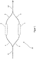
- a common Mach-Zehnder modulator (20) is in Figure 1 shown and works in the following way: Light from an input waveguide (6) is split so that half in an upper arm (4) and a lower arm (3) are each guided in a waveguide. The light in the upper arm (4) is passed through a fast phase modulator (2) with which the speed of light of the light passing through and thus the phase of the exiting light is changed depending on an external electrical signal. A similar phase modulator (1) can be located in the lower arm to increase efficiency. The light from both arms is brought together again via the second arms (8, 9).
- the usual working point of an MZ modulator is a point or the quadrature point at which the output intensity lies in the middle between the minimum and maximum output intensity.
- the corresponding measurement curve usually has its greatest slope and best linearity there. The aim is to keep the modulator at such an operating point with an operating point control.
- such an operating point control can be achieved with the aid of the output signal, in that part of the output signal is branched off and directed to a photodiode.
- the operating point control tries to control the two phase modulators in such a way that the output signal is optimal.
- US 2015/277207 A1 describes an output monitoring method for an optical modulator comprising: branching light into first and second lights; Modulating a phase of the first light in a first waveguide; Modulating a phase of the second light in a second waveguide; Multiplexing the first and second lights to generate interference light and outputting the interference light from first and second output ports; Detecting a difference or a ratio between a part of the interference light from the first output port and a part of the interference light from the second output port; and adjusting an operating point of light based on the detected difference or the detected ratio; and controlling the phase modulation of subsequent light propagating through the first and second waveguides to keep the operating point constant.
- US 2006/034616 A1 describes an automatic bias control for an optical modulator comprising a driver for providing an electrical data signal to the modulator and bias means for providing a bias to the modulator.
- a microprocessor supplies a low-frequency digital modulation signal which is converted into an analog modulation signal by a digital-to-analog converter.
- the analog modulation signal is applied to the bias means (to modulate the bias) or to the driver (to modulate the amplitude of the data signal).
- Intensity detection means are provided for detecting the intensity of the light emitted by the modulator, and an analog-to-digital converter converts the output of the intensity detection means into a digital intensity signal which is passed on to the microprocessor.
- the digital intensity signal is analyzed and the bias means is instructed to adjust the bias based on the analyzed signal.
- the Mach-Zehnder modulator comprises an optical splitter device which is designed to distribute an optical input signal into optical partial signals to at least two optical guide arms, at least one modulation device which is used as an optical phase modulator Phase modulation of the optical input signal is designed in at least one of the at least two optical guide arms, and an optical combining device, wherein the optical combining device is designed to combine the optical partial signals of the at least two optical guide arms.
- the control device comprises a signal comparison device which is designed to compare the optical partial signals of the at least two optical guide arms, at least one control modulation device which is arranged in at least one of the at least two optical guide arms, and a control circuit, the control circuit being configured to regulate an operating point of the Mach-Zehnder modulator by controlling the at least one control modulation device based on the comparison of the optical partial signals by the signal comparison device.
- the optical input signal is passed to the optical splitter device, which is designed to distribute the optical input signal to at least two optical guide arms or to split the optical input signal into a number of optical partial signals, the number of optical partial signals being equal to the number of optical guide arms corresponds to and in each case to direct an optical partial signal to a respective guide arm of the at least two optical guide arms.
- the optical input signal or the partial optical signals can in particular be passed through glass fibers to the optical splitter device.
- the at least two optical guide arms can be designed at least partially as glass fibers or based on glass fibers. It can be advantageous here to provide the at least two optical guide arms made of the same material.
- the Mach-Zehnder modulator can in particular be implemented through monolithic integration on photonic chips and components.
- the optical input signal can in particular be passed through waveguides to the optical splitter device and / or the at least two optical guide arms can be at least partially designed as a waveguide or based on waveguides.
- optical lines or optical signal paths for example for the transmission of optical Input and / or output signals of the Mach-Zehnder modulator can be at least partially based on glass fibers and / or based on waveguides.
- the waveguides can in particular be at least partially based on silicon and / or silicon nitride and / or lithium niobate.
- the optical splitter device can have at least one optical signal input, but is not limited to a specific number of optical signal inputs.
- the optical input signal is passed to the optical splitter device via the at least one optical signal input and is distributed by this to the at least two optical guide arms.
- the optical splitter device can be designed as a Y-distributor and / or as a multimode interferometer.
- the at least one modulation device is designed as a phase modulator.
- each optical guide arm of the at least two optical guide arms can have any number of phase modulators.
- the phase modulators can be designed to reduce or increase a speed of light of an optical partial signal passing through the at least one modulation device, as a result of which a phase of the passing optical signal is influenced after exiting the phase modulator.
- a phase modulator can regulate the speed of light of the optical signal passing through, for example on the basis of an applied electrical or magnetic or electromagnetic signal.
- Thermal or mechanical phase modulators can also be used.
- a first optical guide arm and a second optical guide arm each have an essentially identical phase modulator, whereby an efficient Phase modulation is made possible.
- the optical combining device is designed to combine signals or the optical partial signals which are transmitted via the at least two optical guide arms.
- the optical combining device can have a number of signal inputs of the optical combining device, the number of signal inputs of the optical combining device being equal to or greater than the number of optical guide arms.
- a signal input of the optical combining device is connected to an optical guide arm.
- the optical combining device is designed to receive and combine the optical partial signals, which are transmitted via the guide arms, at the signal inputs of the optical combining device. In this way, in particular, the optical input signal which is distributed to the at least two optical guide arms by the optical splitter device is combined by the optical combining device to form an optical output signal.
- the optical output signal arises from an at least partial superposition of the partial optical signals in the optical guide arms. If the Mach-Zehnder modulator is designed, for example, with two optical guide arms, with the light from both guide arms having the same phase position, constructive interference occurs and the optical output signal is high. If the Mach-Zehnder modulator is designed, for example, with two optical guide arms, the light from the two guide arms having a phase difference of 180 °, destructive interference occurs and the optical output signal is low, the optical output signal preferably disappearing completely.
- the optical combining device has at least one first signal output.
- the optical combining device can be designed as a Y-coupler, preferably as a multimode interferometer.
- the control device is designed to control an operating point of the Mach-Zehnder modulator.
- the control device comprises a Signal comparison device which is designed to compare the optical partial signals of the at least two optical guide arms.
- environmental influences can impair physical properties of the partial optical signals during operation of the Mach-Zehnder modulator.
- temperature differences between the at least two optical guide arms or impairing external electromagnetic fields can cause a relative phase shift between the partial optical signals, thereby changing the combined optical output signal or the operating point of the Mach-Zehnder modulator.
- the signal comparison device is therefore configured to measure each of the optical partial signals or physical properties of each of the optical partial signals and / or to compare the optical partial signals or the physical properties of the optical partial signals with one another. Deviations between the optical partial signals can thus be registered or measured.
- the control device further comprises at least one control modulation device, the at least one control modulation device being designed as a phase modulator.
- each optical guide arm of the at least two optical guide arms can have any number of control modulation devices.
- the at least one control modulation device can be designed to reduce or increase the speed of light of an optical partial signal passing through the at least one control modulation device, thereby influencing a phase of the passing optical partial signal after exiting the at least one control modulation device.
- the at least one control modulation device can regulate the speed of light of the optical signal passing through, for example on the basis of an applied electrical or magnetic or electromagnetic signal.
- thermal, in particular thermo-optical, or mechanical phase modulators can be used. If at least one control modulation device is provided in more than one optical guide arm, the control modulation devices are preferably designed essentially identically, which enables efficient phase modulation.
- the control device further comprises a control circuit which is configured to adjust the operating point of the Mach-Zehnder modulator at least by controlling the at least one control modulation device based on the comparison of the optical partial signals by the signal comparison device or on a comparison output signal of the signal comparison device rules.
- the control circuit can evaluate the comparison of the optical partial signals and control the at least one control modulation device in such a way that a potential impairment of the operating point of the Mach-Zehnder modulator, for example due to environmental influences, is counteracted or such a potential impairment is essentially compensated .
- the signal comparison device and the control device can in particular be designed as a unit which is configured to carry out all functions of the signal comparison device and the control device.
- the signal comparison device and / or the at least one control modulation device is preferably arranged between the optical splitter device and the at least one modulation device.
- “arranged” is not to be understood as limiting in the sense of a geometric arrangement. Rather, it is to be understood here that the signal comparison device can compare the optical partial signals in the at least two optical guide arms after the optical partial signals have been distributed to the at least two optical guide arms by the optical splitter device and before the optical partial signals pass through the at least one modulation device have or a phase of the partial optical signals have been modulated by the at least one modulation device.
- the at least one control modulation device can modulate the partial optical signals in the at least two optical guide arms after the partial optical signals have been distributed to the at least two optical guide arms by the optical splitter device and before the partial optical signals have been distributed to the at least one Modulation device have passed through or a phase of the partial optical signals have been modulated by the at least one modulation device.
- the signal comparison device and the at least one control modulation device are arranged such that at least one optical sub-signal of the optical sub-signals passes through the control modulation device or the phase of at least one optical sub-signal of the optical sub-signals is modulated by the control modulation device before the optical partial signals are compared by the signal comparison device.
- the signal comparison device preferably comprises at least two power dividers, a power divider of the at least two power dividers being arranged in each of the at least two optical guide arms, each power divider of the at least two power dividers being designed to derive a reference signal from the respective partial optical signal.
- the signal comparison device further comprises an optical reference signal combining device which is connected to the at least two power splitters and is designed to convert the at least two reference signals into at least two measurement signals, and a photodetector device which is designed to receive the at least two measurement signals.
- the at least two power dividers are designed to derive a reference signal from an optical partial signal, each reference signal having the same phase information and a lower power or amplitude than the respective optical partial signal from which the reference signal was derived.
- the at least two power dividers thus derive at least two reference signals which are fed to the optical reference signal combining device.
- the Mach-Zehnder modulator is preferably configured so that the distance covered by each optical partial signal between the optical splitter device and the respective power splitter of the at least two power splitters are essentially identical.
- the signal comparison device is preferably configured so that the distance covered by each reference signal between the respective power splitter of the at least two power splitters and the optical reference signal combining device are essentially identical.
- the optical reference signal combining device is designed to combine the reference signals which are received by the reference signal combining device.
- the optical reference signal combining device can have a number of signal inputs of the optical reference signal combining device, the number of signal inputs of the optical reference signal combining device being equal to or greater than the number of the at least two power splitters.
- one signal input of the optical reference signal combining device is connected to one power splitter.
- the optical reference signal combining device is designed to receive and combine the reference signals at the signal inputs of the optical reference signal combining device.
- the optical reference signal combining device comprises at least two signal outputs, the reference signals being combined or converted into at least two measurement signals by the optical reference signal combining device.
- the optical reference signal combining device can in particular be designed so that when the Mach-Zehnder modulator is in the correct operating point, the at least two measurement signals are essentially identical. A deviation of the Mach-Zehnder modulator from the correct operating point can thus be registered simply and efficiently.
- the optical reference signal combining device can in particular also be designed so that when the Mach-Zehnder modulator is in the correct operating point, at least one measurement signal is maximum and at least one measurement signal is minimum or disappears. A deviation of the Mach-Zehnder modulator from the correct operating point can thus be registered simply and efficiently, and furthermore the direction of a required correction phase modulation to restore the correct operating point can be determined, whereby the efficiency of the operating point control is further increased.
- the photodetector device is designed to receive the at least two measurement signals and to convert them into at least one electrical measurement data signal.
- the photodetector device has at least one measurement data output, to which the at least one electrical measurement data signal is forwarded.
- the at least one measurement data output is connected to the control circuit and transmits the at least one electrical measurement data signal to the control circuit.
- At least one control modulation device of the at least one control modulation device is preferably arranged in one of the at least two optical guide arms between one of the at least two power splitters and the optical splitter device.
- “arranged” is not to be understood as limiting in the sense of a geometric arrangement. Rather, it is to be understood here that the at least one control modulation device of the at least one control modulation device can modulate a phase of at least one optical partial signal in at least one of the at least two optical guide arms, after the optical partial signals have passed through the optical splitter device to the at least two optical partial signals Guide arms were distributed, and before the optical partial signals have passed through the at least two power splitters or a reference signal for each of the optical partial signals has been derived from the at least two power splitters.
- This in particular enables at least one feedforward loop within the Mach-Zehnder modulator for operating point control.
- Each of the at least two power splitters is preferably designed to derive a maximum of 20%, preferably a maximum of 5%, more preferably a maximum of 2%, most preferably a maximum of 1% of a power of the respective optical partial signal. Furthermore, each of the at least two power splitters is preferably designed to derive at least 0.01%, preferably at least 0.05%, of a power of the respective optical partial signal. This ensures that the signal comparison device is supplied with sufficiently strong optical signals for comparing the optical partial signals, and that sufficiently strong optical partial signals are passed on to the optical combining device.
- the at least two power dividers are preferably essentially identical educated. This enables a reliably identical derivation of the at least two reference signals.
- Each of the at least two power dividers is preferably designed as a Y-splitter and / or as a directional coupler and / or as a multimode interferometer.
- the optical reference signal combining device and the optical combining device are preferably designed essentially identically. As a result, the at least two reference signals and the at least two optical partial signals from essentially identical optical components are combined, which enables reliable and efficient control of the operating point.
- the optical splitter device and / or the optical combining device and / or the optical reference signal combining device is preferably designed as a multimode interferometer.
- the photodetector device preferably has at least two photodiodes, each of the at least two photodiodes being designed to receive one of the at least two measurement signals, each of the at least two photodiodes having a measurement data output which is connected to the control circuit.
- the at least two photodiodes can be designed identically.
- each of the at least two measurement signals can be converted into an electrical measurement data signal by one of the at least two photodiodes.
- the photodetector device is not limited to photodiodes, and thus other photodetectors can also be used, for example photodetectors based on the external and / or internal photoelectric effect.
- the photodetector device is preferably designed as a symmetrical or differential photodetector, the symmetrical or differential photodetector having at least one measurement data output which is connected to the control circuit.
- the optical measurement signals can be sent directly from the Photodetector are converted into an electrical difference signal, the photodetector device being able to determine the comparison between the partial optical signals.
- the at least one control modulation device is preferably designed as a thermo-optical phase modulator.
- the at least one control modulation device preferably comprises at least two control modulation devices, each of the at least two optical guide arms having at least one of the at least two control modulation devices. This enables efficient control of the operating point.
- the optical combining device preferably comprises an optical monitor signal output which is connected to a monitor photodiode, the monitor photodiode being designed to receive an optical monitor signal at the optical monitor signal output and to supply an electrical monitor data signal based thereon to the control circuit, the control circuit being configured to regulate an operating point of the Mach-Zehnder modulator by controlling the at least one control modulation device based on the comparison of the optical partial signals by the signal comparison device and the electrical monitor data signal of the monitor photodiode.
- This enables operating point control based on the optical partial signals in the at least two optical guide arms and based on the optical monitor signal downstream of the optical combining device, ie based on a feedforward and a feedback loop.
- control circuit could determine the operating point based on the comparison of the partial optical signals and determine the operating point based on the monitor data signal, with a comparison of the two operating point determinations providing a conclusion about potential environmental influences on a section of the Mach-Zehnder modulator between the control device and the monitor Photodiode, for example overheating of the at least one modulation device; enables.
- the optical combining device preferably comprises an optical transmission signal output, the Mach-Zehnder modulator having a transmitter mode in which an optical transmission signal is generated based on the optical input signal at the optical transmission signal output, and more preferably has a receiver mode in which the optical input signal is directed to the monitor photodiode and, in particular, is converted into an electrical data output signal.
- the optical splitter device is configured to distribute the optical input signal to the at least two optical guide arms.
- the at least one modulation device is designed to modulate phases of the separate optical partial signals which are transmitted along the at least two optical guide arms.
- the optical combining device is configured to combine the optical partial signals after their phase modulation, the at least one modulation device and the optical combining device being designed so that the optical transmission signal is generated at the optical transmission signal output.
- data can be transmitted to the transmission signal by means of a controlled phase modulation and sent via the optical transmission signal output.
- the monitor photodiode which is connected to the monitor signal output, can be used in the transmitter mode to control an operating point of the Mach-Zehnder modulator.
- the optical splitter device is configured to distribute the optical input signal to the at least two optical guide arms.
- the at least one modulation device and the optical combining device are designed so that the optical monitor signal, taking into account the derived reference signals, corresponds essentially completely to the optical input signal, the optical monitor signal being essentially completely passed to the optical monitor signal output.
- the monitor photodiode is connected to the optical monitor signal output and configured to convert the optical monitor signal into an electrical data output signal. This allows data that are transmitted by the optical input signal to be received by the Mach-Zehnder modulator in receiver mode on the monitor photodiode and processed further electronically.
- the control circuit is preferably also configured to control the at least one modulation device at least partially, in particular based on the comparison of the optical partial signals by the signal comparison device.
- the operating point regulation can additionally or alternatively be made possible via the at least one modulation device.
- the use of the control modulation devices can thus be dispensed with, and the working point control can be carried out entirely via the at least one modulation device.
- the control circuit preferably further comprises a diagnostic device.
- the diagnostic device is designed to register errors in the at least two power splitters and / or the optical reference signal combining device and / or the photodetector and / or the at least one control modulation device.
- the operating point can be determined over a predetermined period of time, for example at least 5 seconds and / or a maximum of 1 minute, the diagnostic device determining unexpectedly large deviations in the operating points.
- the diagnostic device can mark such a strong deviation as a potential error and check the functionality of the at least two power dividers and / or the optical reference signal combining device and / or the photodetector and / or the at least one control modulation device.
- the at least one control modulation device can be controlled by a continuously or periodically or aperiodically varying diagnostic signal, whereby a resulting change in the operating point allows conclusions to be drawn about potentially defective components. If, for example, no change in the operating point is detected despite the varying diagnostic signal, the diagnostic device can identify this as a fault in the at least one Rule modulation device can be interpreted, with the at least one rule modulation device being able to determine a faulty rule modulation device by separately controlling each rule modulation device.
- an error in the at least two power dividers and / or the optical reference signal combining device and / or the photodetector can also be determined.
- the diagnostic device can transmit an error message, for example to a user and / or an external computer system, wherein the error message can additionally contain information about the defective components.
- Another aspect relates to a method for operating point control of a Mach-Zehnder modulator, comprising providing a Mach-Zehnder modulator with a control device, the Mach-Zehnder modulator being designed with the control device according to one of the embodiments described above, and actuation the at least one control modulation device and / or the at least one modulation device based on the comparison of the optical partial signals by the signal comparison device.
- Figure 1 shows a Mach-Zehnder modulator 20, which is designed according to the prior art.
- Figure 1 reference is made to the introduction.
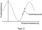
- Figure 2 shows a graph of a quadrature point of a Mach-Zehnder modulator.
- the usual working point of a Mach-Zehnder modulator is a point or the quadrature point at which the output intensity lies in the middle between the minimum and maximum output intensity.
- the corresponding measurement curve usually has its greatest slope and best linearity there.
- the characteristic curve of a Mach-Zehnder modulator shown in FIG Figure 2 is shown as the optical output power in an optical signal output of the Mach-Zehnder modulator over the phase shift of the light in the two optical guide arms. Without a phase shift, there is constructive interference in a signal combiner for the optical signal output and the output power is maximum.
- the output power Due to the increasing phase shift, the output power initially drops and decreases with a phase shift of 180 ° or ⁇ / 2 Minimum. If the phase shift continues, the output power increases again.
- the points with the maximum or minimum slope of the characteristic are the quadrature points and the mostly desired working points of the Mach-Zehnder modulator. While in Figure 2 If only one quadrature point is marked, it is to be indicated that several quadrature points exist, with a set of quadrature points including all points of the characteristic curve at which the slope is maximum and / or minimum. It is therefore desirable to keep the Mach-Zehnder modulator at such an operating point with an operating point control.
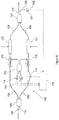
- Figure 3 shows a Mach-Zehnder modulator 100 with a control device for operating point control.
- the Mach-Zehnder modulator 100 has, in particular, an optical splitter device 105 which is designed to distribute an optical input signal into optical partial signals on two optical guide arms 103, 104 .
- the optical splitter device 105 has two optical signal inputs 106, 114 , via which the optical input signal can be transmitted to the optical splitter device 105.
- the optical splitter device 105 is designed, for example, as a 2 ⁇ 2 multimode interferometer.
- the optical splitter device 105 divides the optical input signal into two optical partial signals, which are respectively passed to the first guide arm 103 and the second guide arm 104 , the optical splitter device 105 preferably splitting the optical input signal into identical optical partial signals.
- the partial optical signals each pass through a power splitter 111, 112, a power splitter being formed in the first optical guide arm 103 and the second optical guide arm 104 .
- the first optical guide arm 103 and the second optical guide arm 104 are configured here so that the distance covered by each optical partial signal between the optical splitter device 105 and the respective power splitter 111, 112 are essentially identical.
- the two power splitters 111, 112 are arranged such that each of the optical partial signals first passes through the respective power splitter 111, 112 before the respective optical partial signal hits one of the two modulation devices 101, 102 .
- Each of the two power splitters 111, 112 branches off a reference signal from the respective optical partial signal, the respective reference signal having the same optical properties but a lower intensity or amplitude than the optical partial signal from which it was derived.
- the first reference signal is branched off from the first power splitter 112 and transmitted to a reference signal combining device 113 via a first reference signal conductor 119.
- the second reference signal is branched off from the second power splitter 111 and transmitted to the reference signal combining device 113 via a second reference signal conductor 118.
- first reference signal conductor 119 and the second reference signal conductor 118 are configured so that a distance covered by the first reference signal in the first reference signal conductor 119 is essentially identical to a distance covered by the second reference signal in the second reference signal conductor 118 .
- the optical reference signal combining device 113 is designed to combine the two reference signals.
- the optical reference signal combining device 113 has in particular two optical signal inputs, one signal input of the optical reference signal combining device 113 being connected to a power splitter 111, 112 via one of the two reference signal conductors 118, 119 .
- the optical reference signal combiner 113 is adapted to receive and reference signals at the signal inputs of the optical reference signal combiner 113 to combine.
- the reference signal combining device 113 can in particular be designed as a 2 ⁇ 2 multimode interferometer.
- the optical reference signal combining device 113 comprises at least two signal outputs, the reference signals being combined or converted into two measurement signals by the optical reference signal combining device 113.
- the optical reference signal combining device 113 can in particular be designed so that when the Mach-Zehnder modulator 100 is in the correct operating point, the at least two measurement signals are essentially identical.
- the optical reference signal combining device so that when the Mach-Zehnder modulator 100 is in the correct operating point, at least one measurement signal is maximum and at least one measurement signal is minimum or disappears.
- One measurement signal of the two measurement signals is generated at one of the two signal outputs of the reference signal combining device 113.
- the Mach-Zehnder modulator 100 also has a photodetector device which is designed to receive the at least two measurement signals and to convert them into at least one electrical measurement data signal.
- the photodetector device is designed, for example, as a first photodiode 115 and a second photodiode 114 .
- the first photodiode 115 also has a first measurement data output, at which a first electrical measurement data signal is generated and forwarded by the first photodiode 115.
- the second photodiode 114 also has a second measurement data output, at which a second electrical measurement data signal is generated and forwarded by the second photodiode 114.
- each of the two measurement data outputs is connected to a control circuit 116 and transmits the at least one electrical measurement data signal to control circuit 116.
- the two power dividers 111, 112, the optical reference signal combining device 113 and the two photodiodes 114, 115 are here components of a signal comparison device of the control device.
- the signal comparison device is thus configured in particular to measure each of the optical partial signals or physical properties of each of the optical partial signals and / or to compare the optical partial signals or the physical properties of the optical partial signals with one another. Deviations between the optical partial signals can thus be registered or measured.
- the control circuit 116 is configured to regulate the operating point of the Mach-Zehnder modulator 100 at least by controlling a control modulation device 117 based on the comparison of the partial optical signals.
- the control circuit 116 can be designed in particular be to receive and compare the two measurement data signals from the first photodiode 115 and the second photodiode 114.
- the control circuit 116 can evaluate the comparison of the partial optical signals and control a control modulation device 117 in such a way that a potential impairment of the operating point of the Mach-Zehnder modulator 100 by environmental influences is counteracted or such a potential impairment is essentially compensated.
- the control device further comprises the control modulation device 117, the control modulation device 117 being designed as a phase modulator.
- the rule modulation device 117 is designed to reduce or increase a speed of light of an optical partial signal passing through the control modulation device 117 , whereby a phase of the passing optical partial signal after exiting the control modulation device 117 is influenced.
- the control modulation device 117 can regulate the speed of light of the optical signal passing through, for example on the basis of an applied electrical or magnetic or electro-magnetic signal.
- thermal, in particular thermo-optical, or mechanical phase modulators can be used.
- the two power splitters 111, 112 or the signal comparison device and the control modulation device 117 are arranged between the optical splitter device 105 and two modulation devices 101, 102 , one modulation device 101, 102 being arranged in each optical guide arm 103, 104 .
- each optical partial signal passes through a power splitter 111, 112 of the signal comparison device after the optical partial signals have been distributed to the at least two optical guide arms 103, 104 by the optical splitter device 105 , and before the first optical partial signal the first modulation device 101 and before the second optical partial signal has passed through the second modulation device 102 or a phase of the first optical partial signal has been modulated by the first modulation device 101 and a phase of the second optical partial signal has been modulated by the second Modulation device 102 was modulated.
- control modulation device 117 is arranged such that the control modulation device 117 can modulate the first optical partial signal in the first optical guide arm 103 after the optical partial signals have been distributed to the two optical guide arms 103, 104 by the optical splitter device 105 , and before the optical partial signals are compared by the signal comparison device or the optical partial signals pass through the two power splitters 111, 112.
- the Mach-Zehnder modulator comprises the two modulation devices 101, 102, which are designed as optical phase modulators for phase modulating the first and second optical partial signals in one of the two optical guide arms 103, 104 in each case.
- the first optical guide arm 103 has the first modulation device 101 and the second optical guide arm 104 has the second modulation device 102 .
- the first and second modulation devices 101, 102 are designed to reduce or increase a speed of light of the optical partial signal passing through the respective modulation device 101, 102 , whereby a phase of the passing optical partial signal after exiting the respective modulation device 101, 102 is influenced.
- the respective modulation device 101, 102 can regulate the speed of light of the optical partial signal passing through, for example on the basis of an applied electrical or magnetic or electromagnetic signal. Thermal or mechanical phase modulators can also be used.
- the first optical guide arm 103 and the second optical guide arm 104 preferably each have an essentially identical modulation device 101, 102 , which enables efficient phase modulation.
- the first modulation device 101 and the second modulation device 102 can be controlled by an external electrical control signal, which is shown in Figure 3 is exemplified by arrows.
- the Mach-Zehnder modulator 100 also has an optical combining device 107 which is designed to combine the two optical partial signals which are transmitted to the optical combining device 107 via the first optical guide arm 103 and the second optical guide arm 104.
- the optical combining device 107 has two optical signal inputs.
- an optical signal input 108, 109 of the optical combining device 107 is connected to one of the two optical guide arms 103, 104.
- the optical combining means 107 is configured, the optical sub-signals, which are transmitted via the two guide arms 103, 104 to receive and to the signal inputs of the optical combiner 107 to combine.
- the optical input signal which is distributed to the at least two optical guide arms by the optical splitter device 105 is combined by the optical combining device 107 to form an optical output signal.
- the optical output signal arises from an at least partial superposition of the two optical partial signals. If the light from both optical guide arms 103, 104 has the same phase position, constructive interference occurs and the optical output signal is high. If the light from the two optical guide arms 103, 104 has a phase difference of 180 °, destructive interference occurs and the optical output signal is low, the optical output signal preferably disappearing completely.
- the optical combining device also has two optical signal outputs 110, 130 to which the optical output signal can be routed.
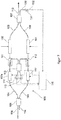
- Figure 4 shows a Mach-Zehnder modulator 100 with a control device for operating point control according to FIG Figure 3 , the Mach-Zehnder modulator 100 being supplemented by a second control modulation device 117a .
- the second control modulation device 117 a can be arranged in the second optical guide arm 104 at a position identical to the position of the first control modulation device 117 in the first optical guide arm 103 .
- the first rule modulation device 117 can be embodied identically to the second rule modulation device 117a .
- Figure 5 shows a Mach-Zehnder modulator 100 with a control device for operating point control according to FIG Figure 3 , wherein the control circuit 116 of the Mach-Zehnder modulator 100 is additionally connected to the first modulation device 101 and the second modulation device 102.
- the control circuit 116 is further configured to control the first modulation device 101 at least partially, in particular based on the comparison of the optical partial signals by the signal comparison device.
- the control circuit 116 is further configured to control the second modulation device 102 at least partially, in particular based on the comparison of the optical partial signals by the signal comparison device.
- the operating point regulation is additionally or alternatively made possible via the two modulation devices 101, 102 .
- control of the control modulation device 117 can thus be dispensed with, and the operating point control can be carried out entirely via the two modulation devices 101, 102.
- the operating point of the Mach-Zehnder modulator 100 can thereby continue to be regulated, even if the regulating modulation device 117 is faulty or broken.
- Figure 6 , Figure 7 and Figure 8 each show a Mach-Zehnder modulator 100 with a control device for operating point control according to FIG Figure 3 , Figure 4 and Figure 5 , the Mach-Zehnder modulator 100 being expanded by a monitor photodiode 131 in each case.
- the optical combining device 107 comprises an optical monitor signal output 130, which is connected to the monitor photodiode 131 , the monitor photodiode 131 being designed to receive an optical monitor signal at the optical monitor signal output 130 and to supply an electrical monitor data signal based thereon to the control circuit 116 .
- the monitor photodiode 131 has at least one monitor data signal output 132 via which the electrical Monitor data signal is transmitted.
- the control circuit 116 is configured in particular to regulate an operating point of the Mach-Zehnder modulator 100 by controlling the at least one control modulation device 117, 117a based on the comparison of the optical partial signals by the signal comparison device and the electrical monitor data signal of the monitor photodiode 131 .
- This enables operating point control based on the optical partial signals in the two optical guide arms 103, 104 and based on the optical monitor signal downstream of the optical combining device 107 , ie based on a feedforward and a feedback loop.
- the term “essentially” is to be understood as comprehensively minor manufacturing and environmental-related deviations.
Landscapes
- Physics & Mathematics (AREA)
- Nonlinear Science (AREA)
- General Physics & Mathematics (AREA)
- Optics & Photonics (AREA)
- Optical Modulation, Optical Deflection, Nonlinear Optics, Optical Demodulation, Optical Logic Elements (AREA)
Description
- Die Erfindung betrifft einen Mach-Zehnder-Modulator mit einer Regelvorrichtung zur Arbeitspunktregelung und ein Verfahren zur Arbeitspunktregelung eines solchen Mach-Zehnder-Modulators.
- Die Erfindung liegt auf dem Gebiet der Kommunikationstechnologie, insbesondere auf den Gebieten der optischen Datenübertragungstechnologien. Bei schnellen optischen Übertragungsstrecken werden nicht mehr direkt modulierte, sondern extern modulierte Laser eingesetzt, wobei die externe Modulation üblicherweise durch Mach-Zehnder-Modulatoren erfolgt. Hierfür werden im Wesentlichen Mach-Zehnder-Modulatoren auf Basis von Lithium-Niobat eingesetzt. Die fortschreitende Entwicklung der integrierten Siliziumphotonik ermöglicht jedoch auch Mach-Zehnder-Modulatoren auf Siliziumbasis in Form von photonischen Chips.
- Ein üblicher Mach-Zehnder-Modulatoren (20) ist in
Figur 1 dargestellt und funktioniert auf folgende Weise: Licht aus einem Eingangswellenleiter (6) wird aufgespalten, so dass jeweils die Hälfte in einem oberen Arm (4) und einem unteren Arm (3) jeweils in einem Wellenleiter geführt wird. Das Licht im oberen Arm (4) wird durch einen schnellen Phasenmodulator (2) geführt, mit dem in Abhängigkeit eines von außen angelegen, elektrischen Signals die Lichtgeschwindigkeit des durchtretenden, und damit die Phase des austretenden Lichts geändert wird. Ein gleichartiger Phasenmodulator (1) kann sich zur Effizienzsteigerung im unteren Arm befinden. Das Licht aus beiden Armen wird über die zweiten Arme (8, 9) wieder zusammen geführt. Je nach relativer Phasenlage der Lichtanteile aus dem oberen Arm (4, 8) und dem unteren Arm (3, 9) ergibt sich konstruktive oder destruktive Interferenz und eine Amplitudenmodulation des Lichts im Ausgangswellenleiter (10) in Abhängigkeit des an die Phasenmodulatoren (1, 2) angelegten elektrischen Signals. - Hierbei können Unterschiede in den einzelnen Armen und Temperaturdifferenzen eine Regelung des Arbeitspunktes des MZ-Modulators erforderlich machen, so dass am Ausgang das gewünschte Signal erzeugt wird. Der übliche Arbeitspunkt eines MZ-Modulators ist ein oder der Quadraturpunkt, bei dem die Ausgangsintensität gerade in der Mitte zwischen minimaler und maximaler Ausgangsintensität liegt. Üblicherweise hat die entsprechende Messkurve dort ihre größte Steigung und beste Linearität. Ziel ist es, den Modulator mit einer Arbeitspunktregelung in einem solchen Arbeitspunkt zu halten.
- Bei herkömmlichen Mach-Zehnder-Modulatoren lässt sich eine solche Arbeitspunktregelung mit Hilfe des Ausgangssignals bewerkstelligen, indem ein Teil des Ausgangssignals abgezweigt und auf eine Photodiode geleitet wird. Die Arbeitspunktregelung versucht hierbei die beiden Phasenmodulatoren so anzusteuern, dass das Ausgangssignal optimal wird.
-
US 2015/277207 A1 beschreibt ein Ausgangsüberwachungsverfahren für einen optischen Modulator, umfassend: Verzweigen von Licht in erstes und zweites Licht; Modulieren einer Phase des ersten Lichts in einem ersten Wellenleiter; Modulieren einer Phase des zweiten Lichts in einem zweiten Wellenleiter; Multiplexen des ersten und des zweiten Lichts, um Interferenzlicht zu erzeugen, und Ausgeben des Interferenzlichts von einem ersten und zweiten Ausgangsport; Erfassen einer Differenz oder eines Verhältnisses zwischen einem Teil des Interferenzlichts von dem ersten Ausgangsport und einem Teil des Interferenzlichts von dem zweiten Ausgangsport; und Einstellen eines Arbeitspunkts von Licht basierend auf der erfassten Differenz oder dem erfassten Verhältnis; und Steuern der Phasenmodulation von Folgelicht, das sich durch den ersten und den zweiten Wellenleiter ausbreitet, um den Arbeitspunkt konstant zu halten. -
US 2006/034616 A1 beschreibt eine automatische Vorspannungssteuerung für einen optischen Modulator, umfassend einen Treiber zum Liefern eines elektrischen Datensignals an den Modulator und Vorspannungsmittel zum Liefern einer Vorspannung an den Modulator. Ein Mikroprozessor liefert ein niederfrequentes digitales Modulationssignal, das von einem Digital-Analog-Wandler in ein analoges Modulationssignal umgewandelt wird. Das analoge Modulationssignal wird an die Vorspannungsmittel (um die Vorspannung zu modulieren) oder an den Treiber (um die Amplitude des Datensignals zu modulieren) angelegt. Intensitätserfassungsmittel zum Erfassen der Intensität des vom Modulator abgegebenen Lichts sind vorgesehen, und ein Analog-Digital-Wandler wandelt die Ausgabe der Intensitätserfassungsmittel in ein digitales Intensitätssignal um, das an den Mikroprozessor weitergeleitet wird. Das digitale Intensitätssignal wird analysiert, und die Vorspannungsmittel werden angewiesen, die Vorspannung auf der Basis des analysierten Signals einzustellen. - Es ist daher die Aufgabe der vorliegenden Erfindung, einen Mach-Zehnder-Modulator mit einem einfachen und effizienten Aufbau zur Arbeitspunktregelung, sowie ein effizientes Verfahren zur Arbeitspunktregelung bereitzustellen.
- Diese Aufgabe wird insbesondere durch einen Mach-Zehnder-Modulator mit einer Regelvorrichtung gemäß Anspruch 1 und einem Verfahren zur Arbeitspunktregelung für einen Mach-Zehnder-Modulator gemäß Anspruch 15 gelöst. Die Erfindung ist hierbei durch die unabhängigen Ansprüche definiert, wobei bevorzugte Ausführungsformen den Gegenstand der abhängigen Ansprüche bilden.
- Ein Aspekt betrifft einen Mach-Zehnder-Modulator mit einer Regelvorrichtung zur Arbeitspunktregelung, umfassend einen Mach-Zehnder-Modulator und einer Regelvorrichtung. Der Mach-Zehnder-Modulator umfasst eine optische Teilereinrichtung, welche ausgelegt ist, ein optisches Eingangssignal in optische Teilsignale auf mindestens zwei optische Führungsarme zu verteilen, mindestens eine Modulationseinrichtung, welche als optischer Phasenmodulator zur Phasenmodulation des optischen Eingangssignals in mindestens einem der mindestens zwei optischen Führungsarme ausgelegt ist, und eine optische Kombiniereinrichtung, wobei die optische Kombiniereinrichtung ausgelegt ist, die optischen Teilsignale der mindestens zwei optischen Führungsarme zu kombinieren. Die Regelvorrichtung umfasst eine Signal-Vergleichseinrichtung, welche ausgelegt ist, die optischen Teilsignale der mindestens zwei optischen Führungsarme zu vergleichen, mindestens eine Regel-Modulationseinrichtung, welche in mindestens einem der mindestens zwei optischen Führungsarme angeordnet ist, und eine Regelschaltung, wobei die Regelschaltung konfiguriert ist, einen Arbeitspunkt des Mach-Zehnder-Modulators durch Ansteuerung der mindestens einen Regel-Modulationseinrichtung basierend auf dem Vergleich der optischen Teilsignale durch die Signal-Vergleichseinrichtung zu regeln. Hierdurch wird eine effiziente und einfache Arbeitspunktregelung ermöglicht, welche nicht einen Teil eines optischen Ausgangssignals benötigt bzw. abzweigt.
- Das optische Eingangssignal wird hierbei an die optische Teilereinrichtung geleitet, welche ausgelegt ist, das optische Eingangssignal auf mindestens zwei optische Führungsarme zu verteilen bzw. das optische Eingangssignal in eine Anzahl von optischen Teilsignalen zu zerteilen, wobei die Anzahl der optischen Teilsignale der Anzahl von optischen Führungsarmen entspricht und jeweils ein optisches Teilsignal auf jeweils einen Führungsarm der mindestens zwei optische Führungsarme zu leiten. Das optische Eingangssignal kann bzw. die optischen Teilsignale können hierbei insbesondere durch Glasfasern an die optische Teilereinrichtung geleitet werden. Die mindestens zwei optischen Führungsarme können zumindest teilweise als Glasfasern bzw. auf Basis von Glasfasern ausgebildet sein. Hierbei kann es vorteilhaft sein, die mindestens zwei optischen Führungsarme aus dem gleichem Material bereitzustellen.
- Der Mach-Zehnder-Modulator kann insbesondere durch monolithische Integration auf photonischen Chips und Bauteilen realisiert werden. Das optische Eingangssignal kann hierbei insbesondere durch Wellenleiter an die optische Teilereinrichtung geleitet werden und/oder die mindestens zwei optischen Führungsarme können zumindest teilweise als Wellenleiter bzw. auf Basis von Wellenleitern ausgebildet sein. Insbesondere gilt im Rahmen dieser Beschreibung, dass im Fall einer Realisierung des Mach-Zehnder-Modulators durch monolithische Integration auf einem photonischen Chip und/oder Bauteilen bzw. auf photonischen Chips und/oder Bauteilen optische Leitungen bzw. optische Signalstrecken, beispielsweise zur Übertragung von optischen Eingangs- und/oder Ausgangssignalen, des Mach-Zehnder-Modulators zumindest teilweise auf Basis von Glasfasern und/oder auf Basis von Wellenleitern ausgebildet sein können. Die Wellenleiter können hierbei insbesondere zumindest teilweise auf Basis von Silizium und/oder Siliziumnitrid und/oder Lithiumniobat ausgebildet sein.
- Die optische Teilereinrichtung kann mindestens einen optischen Signaleingang aufweisen, ist jedoch nicht auf eine bestimmte Anzahl von optischen Signaleingängen beschränkt. Das optische Eingangssignal wird hierbei über den mindestens einen optischen Signaleingang an die optische Teilereinrichtung geleitet, und durch diese auf die mindestens zwei optischen Führungsarme verteilt. Die optische Teilereinrichtung kann hierbei als Y-Verteiler und/oder als Multimode-Interferometer ausgebildet sein.
- Die mindestens eine Modulationseinrichtung ist als Phasenmodulator ausgebildet. Hierbei kann jeder optische Führungsarm der mindestens zwei optischen Führungsarme eine beliebige Anzahl von Phasenmodulatoren aufweisen. Die Phasenmodulatoren können ausgebildet sein, eine Lichtgeschwindigkeit eines die mindestens eine Modulationseinrichtung durchlaufenden optischen Teilsignals zu reduzieren oder zu erhöhen, wodurch eine Phase des durchlaufenden optischen Signals nach Austritt aus dem Phasenmodulator beeinflusst wird. Hierfür kann ein Phasenmodulator beispielsweise aufgrund eines angelegten elektrischen bzw. magnetischen bzw. elektro-magnetischen Signals die Lichtgeschwindigkeit des durchlaufenden optischen Signals regeln. Ferner können thermische oder mechanische Phasenmodulatoren verwendet werden. Bevorzugt weisen ein erster optischer Führungsarm und ein zweiter optischer Führungsarm jeweils einen im Wesentlichen identischen Phasenmodulator auf, wodurch eine effiziente Phasenmodulation ermöglicht wird.
- Die optische Kombiniereinrichtung ist ausgelegt, Signale bzw. die optischen Teilsignale, welche über die mindestens zwei optischen Führungsarme übermittelt werden, zu kombinieren. Hierzu kann die optische Kombiniereinrichtung eine Anzahl von Signaleingängen der optischen Kombiniereinrichtung aufweisen, wobei die Anzahl von Signaleingängen der optischen Kombiniereinrichtung gleich groß oder größer ist als die Anzahl von optischen Führungsarmen. Insbesondere ist jeweils ein Signaleingang der optischen Kombiniereinrichtung mit jeweils einem optischen Führungsarm verbunden. Ferner ist die optische Kombiniereinrichtung ausgelegt, die optischen Teilsignale, welche über die Führungsarme übermittelt werden, an den Signaleingängen der optischen Kombiniereinrichtung zu empfangen und zu kombinieren. Insbesondere wird hierdurch das optische Eingangssignal, welches durch die optische Teilereinrichtung auf die mindestens zwei optischen Führungsarme verteilt wird, durch die optische Kombiniereinrichtung zu einem optischen Ausgangssignal kombiniert. Insbesondere entsteht das optische Ausgangssignal durch eine zumindest teilweise Überlagerung der optischen Teilsignale in den optischen Führungsarmen. Ist der Mach-Zehnder-Modulator beispielsweise mit zwei optischen Führungsarmen ausgebildet, wobei das Licht aus beiden Führungsarmen die gleiche Phasenlage aufweist, entsteht konstruktive Interferenz, und das optische Ausgangssignal ist hoch. Ist der Mach-Zehnder-Modulator beispielsweise mit zwei optischen Führungsarmen ausgebildet, wobei das Licht aus beiden Führungsarmen einen Phasenunterschied von 180° aufweist, entsteht destruktive Interferenz, und das optische Ausgangssignal ist niedrig, wobei das optische Ausgangssignal bevorzugt vollständig verschwindet.
- Die optische Kombiniereinrichtung weist mindestens einen ersten Signalausgang auf. Die optische Kombiniereinrichtung kann hierfür als Y-Koppler, bevorzugt als Multimode-Interferometer ausgebildet sein.
- Die Regelvorrichtung ist ausgelegt, einen Arbeitspunkt des Mach-Zehnder-Modulators zu regeln. Hierzu umfasst die Regelvorrichtung eine Signal-Vergleichseinrichtung, welche ausgelegt ist, die optischen Teilsignale der mindestens zwei optischen Führungsarme zu vergleichen. Insbesondere können während des Betriebs des Mach-Zehnder-Modulators Umwelteinflüsse physikalische Eigenschaften der optischen Teilsignale beeinträchtigen. So können beispielsweise Temperaturdifferenzen der mindestens zwei optischen Führungsarme oder beeinträchtigende externe elektromagnetische Felder beispielsweise eine relative Phasenverschiebung zwischen den optischen Teilsignalen bewirken, wodurch das kombinierte optische Ausgangssignal bzw. der Arbeitspunkt des Mach-Zehnder-Modulators verändert wird. Die Signal-Vergleichseinrichtung ist daher konfiguriert, jedes der optischen Teilsignale bzw. physikalische Eigenschaften jedes der optischen Teilsignale zu messen und/oder die optischen Teilsignale bzw. die physikalischen Eigenschaften der optischen Teilsignale miteinander zu vergleichen. Somit können Abweichungen zwischen den optischen Teilsignalen registriert bzw. gemessen werden.
- Die Regelvorrichtung umfasst ferner mindestens eine Regel-Modulationseinrichtung, wobei die mindestens eine Regel-Modulationseinrichtung als Phasenmodulator ausgebildet ist. Hierbei kann jeder optische Führungsarm der mindestens zwei optischen Führungsarme eine beliebige Anzahl von Regel-Modulationseinrichtungen aufweisen. Die mindestens eine Regel-Modulationseinrichtung kann ausgebildet sein, eine Lichtgeschwindigkeit eines die mindestens eine Regel-Modulationseinrichtung durchlaufenden optischen Teilsignals zu reduzieren oder zu erhöhen, wodurch eine Phase des durchlaufenden optischen Teilsignals nach Austritt aus der mindestens einen Regel-Modulationseinrichtung beeinflusst wird. Hierfür kann die mindestens eine Regel-Modulationseinrichtung beispielsweise aufgrund eines angelegten elektrischen bzw. magnetischen bzw. elektro-magnetischen Signals die Lichtgeschwindigkeit des durchlaufenden optischen Signals regeln. Ferner können thermische, insbesondere thermooptische, oder mechanische Phasenmodulatoren verwendet werden. Ist jeweils mindestens eine Regel-Modulationseinrichtung in mehr als einem optischen Führungsarm vorgesehen, sind die Regel-Modulationseinrichtungen bevorzugt im Wesentlichen identisch ausgebildet, wodurch eine effiziente Phasenmodulation ermöglicht wird.
- Die Regelvorrichtung umfasst ferner eine Regelschaltung, welche konfiguriert ist, den Arbeitspunkt des Mach-Zehnder-Modulators mindestens durch Ansteuerung der mindestens einen Regel-Modulationseinrichtung basierend auf dem Vergleich der optischen Teilsignale durch die Signal-Vergleichseinrichtung bzw. auf einem Vergleichsausgangssignals der Signal-Vergleichseinrichtung zu regeln. Insbesondere kann die Regelschaltung den Vergleich der optischen Teilsignale evaluieren und die mindestens eine Regel-Modulationseinrichtung derart ansteuern, so dass einer potentiellen Beeinträchtigung des Arbeitspunktes des Mach-Zehnder-Modulators, beispielsweise durch Umwelteinflüsse, entgegengewirkt wird bzw. eine solche potentielle Beeinträchtigung im Wesentlichen ausgeglichen wird. Die Signal-Vergleichseinrichtung und die Regelvorrichtung können hierbei insbesondere als eine Einheit ausgebildet sein, welche konfiguriert ist, alle Funktionen der Signal-Vergleichseinrichtung und der Regelvorrichtung auszuführen.
- Vorzugsweise ist die Signal-Vergleichseinrichtung und/oder die mindestens eine Regel-Modulationseinrichtung zwischen der optischen Teilereinrichtung und der mindestens einen Modulationseinrichtung angeordnet. Hierbei ist "angeordnet" nicht beschränkend im Sinne einer geometrischen Anordnung zu verstehen. Vielmehr ist hierbei zu verstehen, dass die Signal-Vergleichseinrichtung die optischen Teilsignale in den mindestens zwei optischen Führungsarmen vergleichen kann, nachdem die optischen Teilsignale durch die optische Teilereinrichtung auf die mindestens zwei optischen Führungsarme verteilt wurden, und bevor die optischen Teilsignale die mindestens eine Modulationseinrichtung durchlaufen haben bzw. eine Phase der optischen Teilsignale durch die mindestens eine Modulationseinrichtung moduliert wurden. Ferner ist hierbei zu verstehen, dass die mindestens eine Regel-Modulationseinrichtung die optischen Teilsignale in den mindestens zwei optischen Führungsarmen modulieren kann, nachdem die optischen Teilsignale durch die optische Teilereinrichtung auf die mindestens zwei optischen Führungsarme verteilt wurden, und bevor die optischen Teilsignale die mindestens eine Modulationseinrichtung durchlaufen haben bzw. eine Phase der optischen Teilsignale durch die mindestens eine Modulationseinrichtung moduliert wurden.
- Besonders bevorzugt sind die Signal-Vergleichseinrichtung und die mindestens eine Regel-Modulationseinrichtung derart angeordnet, so dass mindestens ein optisches Teilsignal der optischen Teilsignale die Regel-Modulationseinrichtung durchläuft bzw. die Phase von mindestens einem optischen Teilsignal der optischen Teilsignale durch die Regel-Modulationseinrichtung moduliert wird, bevor die optischen Teilsignale durch die Signal-Vergleichseinrichtung verglichen werden.
- Vorzugsweise umfasst die Signal-Vergleichseinrichtung mindestens zwei Leistungsteiler, wobei in jedem der mindestens zwei optischen Führungsarme ein Leistungsteiler der mindestens zwei Leistungsteiler angeordnet ist, wobei jeder Leistungsteiler der mindestens zwei Leistungsteiler ausgelegt ist, jeweils ein Referenzsignal von dem jeweiligen optischen Teilsignal abzuleiten. Die Signal-Vergleichseinrichtung umfasst ferner eine optische Referenzsignal-Kombiniereinrichtung, welche mit den mindestens zwei Leistungsteilern verbunden ist und ausgelegt ist, die mindestens zwei Referenzsignale in mindestens zwei Messsignale umzuwandeln, und eine Photodetektoreinrichtung, welche ausgelegt ist, die mindestens zwei Messsignale zu empfangen.
- Die mindestens zwei Leistungsteiler sind hierbei ausgelegt, von jeweils einem optischen Teilsignal ein Referenzsignal abzuleiten, wobei jedes Referenzsignal gleiche Phaseninformationen und eine geringere Leistung bzw. Amplitude wie das jeweilige optische Teilsignal aufweist, von dem das Referenzsignal abgeleitet wurde. Somit leiten die mindestens zwei Leistungsteiler mindestens zwei Referenzsignale ab, welche an die optische Referenzsignal-Kombiniereinrichtung geführt werden. Bevorzugt ist der Mach-Zehnder-Modulator konfiguriert, so dass die zurückgelegte Strecke jedes optischen Teilsignals zwischen der optischen Teilereinrichtung und des jeweiligen Leistungsteilers der mindestens zwei Leistungsteiler im Wesentlichen identisch sind. Bevorzugt ist die Signal-Vergleichseinrichtung konfiguriert, so dass die zurückgelegte Strecke jedes Referenzsignals zwischen dem jeweiligen Leistungsteiler der mindestens zwei Leistungsteiler und der optischen Referenzsignal-Kombiniereinrichtung im Wesentlichen identisch sind.
- Die optische Referenzsignal-Kombiniereinrichtung ist ausgelegt, die Referenzsignale, welche von der Referenzsignal-Kombiniereinrichtung empfangen werden, zu kombinieren. Hierzu kann die optische Referenzsignal-Kombiniereinrichtung eine Anzahl von Signaleingängen der optischen Referenzsignal-Kombiniereinrichtung aufweisen, wobei die Anzahl von Signaleingängen der optischen Referenzsignal-Kombiniereinrichtung gleich groß oder größer ist als die Anzahl der mindestens zwei Leistungsteiler. Insbesondere ist jeweils ein Signaleingang der optischen Referenzsignal-Kombiniereinrichtung mit jeweils einem Leistungsteiler verbunden. Ferner ist die optische Referenzsignal-Kombiniereinrichtung ausgelegt, die Referenzsignale an den Signaleingängen der optischen Referenzsignal-Kombiniereinrichtung zu empfangen und zu kombinieren. Insbesondere umfasst die optische Referenzsignal-Kombiniereinrichtung mindestens zwei Signalausgänge, wobei die Referenzsignale durch die optische Referenzsignal-Kombiniereinrichtung zu mindestens zwei Messsignalen kombiniert bzw. umgewandelt werden. Die optische Referenzsignal-Kombiniereinrichtung kann insbesondere ausgelegt sein, so dass, wenn sich der Mach-Zehnder-Modulator im richtigen Arbeitspunkt befindet, die mindestens zwei Messsignale im Wesentlichen identisch sind. Somit kann eine Abweichung des Mach-Zehnder-Modulators von dem korrekten Arbeitspunkt einfach und effizient registriert werden. Die optische Referenzsignal-Kombiniereinrichtung kann insbesondere auch ausgelegt sein, so dass, wenn sich der Mach-Zehnder-Modulator im richtigen Arbeitspunkt befindet, mindestens ein Messsignal maximal ist und mindestens ein Messsignal minimal ist bzw. verschwindet. Somit kann eine Abweichung des Mach-Zehnder-Modulators von dem korrekten Arbeitspunkt einfach und effizient registriert werden, und ferner kann hierdurch auch die Richtung einer benötigten Korrektur-Phasenmodulation zur Wiederherstellung des korrekten Arbeitspunktes ermittelt werden, wodurch die Effizienz der Arbeitspunktregelung ferner erhöht wird.
- Die Photodetektoreinrichtung ist ausgelegt, die mindestens zwei Messsignale zu empfangen und in mindestens ein elektrisches Messdatensignal umzuwandeln. Hierfür weist die Photodetektoreinrichtung mindestens einen Messdatenausgang auf, an dem das mindestens eine elektrische Messdatensignal weitergeleitet wird. Insbesondere ist der mindestens eine Messdatenausgang mit der Regelschaltung verbunden und übermittelt der Regelschaltung das mindestens eine elektrische Messdatensignal.
- Vorzugsweise ist mindestens eine Regel-Modulationseinrichtung der mindestens einen Regel-Modulationseinrichtung in einem der mindestens zwei optischen Führungsarme zwischen einem der mindestens zwei Leistungsteiler und der optischen Teilereinrichtung angeordnet. Hierbei ist "angeordnet" nicht beschränkend im Sinne einer geometrischen Anordnung zu verstehen. Vielmehr ist hierbei zu verstehen, dass die mindestens eine Regel-Modulationseinrichtung der mindestens einen Regel-Modulationseinrichtungen eine Phase von mindestens einem optischen Teilsignal in mindestens einem der mindestens zwei optischen Führungsarmen modulieren kann, nachdem die optischen Teilsignale durch die optische Teilereinrichtung auf die mindestens zwei optischen Führungsarme verteilt wurden, und bevor die optischen Teilsignale die mindestens zwei Leistungsteiler durchlaufen haben bzw. jeweils ein Referenzsignal für jedes der optische Teilsignale von den mindestens zwei Leistungsteilern abgeleitet wurde. Hierdurch wird insbesondere mindestens ein Feedforward-Loop innerhalb des Mach-Zehnder-Modulators zur Arbeitspunktregelung ermöglicht.
- Vorzugsweise ist jeder der mindestens zwei Leistungsteiler ausgelegt, maximal 20%, bevorzugt maximal 5%, weiter bevorzugt maximal 2%, am meisten bevorzugt maximal 1% einer Leistung des jeweiligen optischen Teilsignals abzuleiten. Ferner ist vorzugsweise jeder der mindestens zwei Leistungsteiler ausgelegt, mindestens 0,01%, bevorzugt mindestens 0,05% einer Leistung des jeweiligen optischen Teilsignals abzuleiten. Hierdurch wird sichergestellt, dass der Signal-Vergleichseinrichtung genügend starke optische Signale zum Vergleich der optischen Teilsignale zugeführt werden, und dass genügend starke optische Teilsignale an die optische Kombiniereinrichtung weitergeführt werden.
- Vorzugsweise sind die mindestens zwei Leistungsteiler im Wesentlichen identisch ausgebildet. Hierdurch wird eine verlässlich identische Ableitung der mindestens zwei Referenzsignale ermöglicht.
- Vorzugsweise ist jeder der mindestens zwei Leistungsteiler als Y-Teiler und/oder als Richtkoppler und/oder als Multimode-Interferometer ausgebildet.
- Vorzugsweise sind die optische Referenzsignal-Kombiniereinrichtung und die optische Kombiniereinrichtung im Wesentlichen identisch ausgebildet. Hierdurch werden die mindestens zwei Referenzsignale und die mindestens zwei optischen Teilsignale von im Wesentlich identischen optischen Bauteilen kombiniert, wodurch eine verlässliche und effiziente Arbeitspunktregelung ermöglicht wird.
- Vorzugsweise ist die optische Teilereinrichtung und/oder die optische Kombiniereinrichtung und/oder die optische Referenzsignal-Kombiniereinrichtung als Multimode-Interferometer ausgebildet.
- Vorzugsweise weist die Photodetektoreinrichtung mindestens zwei Photodioden auf, wobei jede der mindestens zwei Photodioden ausgelegt ist, jeweils eines der mindestens zwei Messsignale zu empfangen, wobei jede der mindestens zwei Photodioden einen Messdatenausgang aufweist, welcher mit der Regelschaltung verbunden ist. Insbesondere können die mindestens zwei Photodioden identisch ausgelegt sein. Somit kann jedes der mindestens zwei Messsignale von jeweils einer der mindestens zwei Photodioden in ein elektrisches Messdatensignal umgewandelt werden. Die Photodetektoreinrichtung ist jedoch nicht auf Photodioden beschränkt, und somit können auch andere Photodetektoren verwendet werden, beispielsweise Photodetektoren basierend auf dem äußeren und/oder inneren photoelektrischen Effekt.
- Vorzugsweise ist die Photodetektoreinrichtung als symmetrischer bzw. differentieller Photodetektor ausgebildet, wobei der symmetrische bzw. differentielle Photodetektor mindestens einen Messdatenausgang aufweist, welcher mit der Regelschaltung verbunden ist. Somit können die optischen Messsignale direkt von dem Photodetektor in ein elektrisches Differenzsignal umgewandelt werden, wobei die Photodetektoreinrichtung hierbei den Vergleich zwischen den optischen Teilsignalen ermitteln kann.
- Vorzugsweise ist die mindestens eine Regel-Modulationseinrichtung als thermooptischer Phasenmodulator ausgebildet.
- Vorzugsweise umfasst die mindestens eine Regel-Modulationseinrichtung mindestens zwei Regel-Modulationseinrichtungen, wobei jeder der mindestens zwei optischen Führungsarme mindestens eine der mindestens zwei Regel-Modulationseinrichtungen aufweist. Hierdurch wird eine effiziente Arbeitspunktregelung ermöglicht.
- Vorzugsweise umfasst die optische Kombiniereinrichtung einen optischen Monitorsignalausgang, welcher mit einer Monitor-Photodiode verbunden ist, wobei die Monitor-Photodiode ausgelegt ist, ein optisches Monitorsignal an dem optischen Monitorsignalausgang zu empfangen und der Regelschaltung ein hierauf basierendes elektrisches Monitordatensignal zuzuführen, wobei die Regelschaltung konfiguriert ist, einen Arbeitspunkt des Mach-Zehnder-Modulators durch Ansteuerung der mindestens einen Regel-Modulationseinrichtung basierend auf dem Vergleich der optischen Teilsignale durch die Signal-Vergleichseinrichtung und dem elektrischen Monitordatensignal der Monitor-Photödiode zu regeln. Somit wird eine Arbeitspunktregelung basierend auf den optischen Teilsignalen in den mindestens zwei optischen Führungsarmen und basierend auf dem optischen Monitorsignal nach der optischen Kombiniereinrichtung ermöglicht, d.h. basierend auf einem Feedforward und einem Feedback-Loop. Ferner könnte hierbei die Regelschaltung den Arbeitspunkt basierend auf dem Vergleich der optischen Teilsignale ermitteln und den Arbeitspunkt basierend auf dem Monitordatensignal ermitteln, wobei ein Vergleich beider Arbeitspunktermittlungen einen Rückschluss auf potentielle Umwelteinflüsse auf einen Abschnitt des Mach-Zehnder-Modulators zwischen der Regelvorrichtung und der Monitor-Photodiode, beispielsweise eine Überhitzung der mindestens einen Modulationseinrichtung; ermöglicht.
- Vorzugsweise umfasst die optische Kombiniereinrichtung einen optischen Transmissionssignalausgang, wobei der Mach-Zehnder-Modulator einen Transmitter-Modus aufweist, in dem ein optisches Transmissionssignal basierend auf dem optischen Eingangssignal an dem optischen Transmissionssignalausgang erzeugt wird, und weiter bevorzugt einen Receiver-Modus aufweist, in dem das optische Eingangssignal an die Monitor-Photodiode gelenkt ist und insbesondere in ein elektrisches Datenausgangssignal umgewandelt wird.
- In dem Transmitter-Modus ist die optische Teilereinrichtung konfiguriert, das optische Eingangssignal auf die mindestens zwei optischen Führungsarme zu verteilen. Die mindestens eine Modulationseinrichtung ist ausgelegt, Phasen der getrennten optischen Teilsignale, welche entlang der mindestens zwei optischen Führungsarme übermittelt werden, zu modulieren. Die optische Kombiniereinrichtung ist konfiguriert, die optischen Teilsignale nach deren Phasenmodulation zu kombinieren, wobei die mindestens eine Modulationseinrichtung und die optische Kombiniereinrichtung ausgelegt sind, so dass das optische Transmissionssignal an dem optischen Transmissionssignalausgang erzeugt wird. Hierbei können durch eine kontrollierte Phasenmodulation Daten auf das Transmissionssignal übertragen werden und über den optischen Transmissionssignalausgang gesendet werden. Die Monitor-Photodiode, welche mit dem Monitorsignalausgang verbunden ist, kann in dem Transmitter-Modus zur Regelung eines Arbeitspunktes des Mach-Zehnder-Modulators verwendet werden.
- In dem Receiver-Modus ist die optische Teilereinrichtung konfiguriert, das optische Eingangssignal auf die mindestens zwei optischen Führungsarme zu verteilen. Die mindestens eine Modulationseinrichtung und die optische Kombiniereinrichtung sind ausgelegt, so dass das optische Monitorsignal unter Berücksichtigung der abgeleiteten Referenzsignale im Wesentlichen vollständig dem optischen Eingangssignal entspricht, wobei das optische Monitorsignal im Wesentlichen vollständig an den optischen Monitorsignalausgang geleitet wird. Die Monitor-Photodiode ist mit dem optischen Monitorsignalausgang verbunden und konfiguriert, das optische Monitorsignal in ein elektrisches Datenausgangssignal umzuwandeln. Hierdurch können Daten, welche durch das optische Eingangssignal übermittelt werden, durch den Mach-Zehnder-Modulator im Receiver-Modus an der Monitor-Photodiode empfangen und elektronisch weiterverarbeitet werden.
- Vorzugsweise ist die Regelschaltung ferner konfiguriert, die mindestens eine Modulationseinrichtung zumindest teilweise, insbesondere basierend auf dem Vergleich der optischen Teilsignale durch die Signal-Vergleichseinrichtung, anzusteuern. Hierdurch kann die Arbeitspunktregelung zusätzlich oder alternativ über die mindestens eine Modulationseinrichtung ermöglicht werden. Somit kann hierbei auf die Verwendung der Regel-Modulationseinrichtungen verzichtet werden, und die Arbeitspunktregelung vollständig über die mindestens eine Modulationseinrichtung erfolgen.
- Vorzugsweise umfasst die Regelschaltung ferner eine Diagnoseeinrichtung. Die Diagnoseeinrichtung ist hierbei ausgelegt, Fehler in den mindestens zwei Leistungsteilern und/oder der optischen Referenzsignal-Kombiniereinrichtung und/oder dem Photodetektor und/oder der mindestens einen Regel-Modulationseinrichtung zu registrieren. Hierbei kann beispielsweise der Arbeitspunkt über einen vorbestimmten Zeitraum, beispielsweise mindestens 5 Sekunden und/oder maximal 1 Minute, ermittelt werden, wobei die Diagnoseeinrichtung unerwartet starke Abweichungen der Arbeitspunkte ermittelt. Die Diagnoseeinrichtung kann eine solche starke Abweichung als potentiellen Fehler markieren und eine Funktionsfähigkeit der mindestens zwei Leistungsteiler und/oder der optischen Referenzsignal-Kombiniereinrichtung und/oder dem Photodetektor und/oder der mindestens einen Regel-Modulationseinrichtung überprüfen. Somit kann beispielsweise die mindestens eine Regel-Modulationseinrichtung durch ein kontinuierlich oder periodisch oder aperiodisch variierendes Diagnosesignal angesteuert werden, wodurch eine resultierende Arbeitspunktveränderung auf potentielle fehlerhafte Bauteile schließen lässt. Sollte beispielsweise keine Veränderung des Arbeitspunktes trotz des variierenden Diagnosesignals festgestellt werden, kann dies von der Diagnoseeinrichtung als Fehler der mindestens einen Regel-Modulationseinrichtung interpretiert werden, wobei durch separates Ansteuern jeder Regel-Modulationseinrichtung der mindestens einen Regel-Modulationseinrichtung eine Ermittlung einer fehlerhaften Regel-Modulationseinrichtung ermöglicht. Durch das Ansteuern der mindestens einen Regel-Modulationseinrichtung durch das kontinuierlich oder periodisch oder aperiodisch variierende Diagnosesignal kann auch ein Fehler in den mindestens zwei Leistungsteilern und/oder der optischen Referenzsignal-Kombiniereinrichtung und/oder dem Photodetektor ermittelt werden. In dem Fall einer Registrierung eines Fehlers durch die Diagnoseeinrichtung, kann die Diagnoseeinrichtung eine Fehlermeldung beispielsweise an einen Benutzer und/oder ein externes Computersystem übermitteln, wobei die Fehlermeldung zusätzlich Informationen über die fehlerhaften Bauteile enthalten kann.
- Ein weiterer Aspekt betrifft ein Verfahren zur Arbeitspunktregelung eines Mach-Zehnder-Modulators, umfassend ein Bereitstellen eines Mach-Zehnder-Modulators mit einer Regelvorrichtung, wobei der Mach-Zehnder-Modulator mit der Regelvorrichtung gemäß einer der oben beschriebenen Ausführungsformen ausgebildet ist, und ein Ansteuern der mindestens einen Regel-Modulationseinrichtung und/oder der mindestens einen Modulationseinrichtung basierend auf dem Vergleich der optischen Teilsignale durch die Signal-Vergleichseinrichtung.
- Die Erfindung wird ferner in nachfolgenden Figuren anhand von illustrativen Ausführungsformen beschrieben. Es zeigen:
- Figur 1:
- eine schematische Ansicht eines Mach-Zehnder-Modulators gemäß dem Stand der Technik;
- Figur 2:
- eine graphische Darstellung eines Quadraturpunktes eines Mach-Zehnder-Modulators;
- Figur 3:
- eine schematische Darstellung eines Mach-Zehnder-Modulators mit einer Regelvorrichtung;
- Figur 4
- eine schematische Darstellung eines Mach-Zehnder-Modulators gemäß
Figur 3 mit einer zweiten Regel-Modulationseinrichtung; - Figur 5
- eine schematische Darstellung eines Mach-Zehnder-Modulators gemäß
Figur 3 mit einer erweiterten Regelschaltung; - Figur 6
- eine schematische Darstellung eines Mach-Zehnder-Modulators gemäß
Figur 3 mit einer Monitor-Photodiode; - Figur 7
- eine schematische Darstellung eines Mach-Zehnder-Modulators gemäß
Figur 4 mit einer Monitor-Photodiode; - Figur 8:
- eine schematische Darstellung eines Mach-Zehnder-Modulators gemäß
Figur 5 mit einer Monitor-Photodiode. -
Figur 1 zeigt einen Mach-Zehnder-Modulator 20, welcher gemäß dem Stand der Technik ausgebildet ist. Für eine eingehende Beschreibung vonFigur 1 wird auf die Einleitung verwiesen. -
Figur 2 zeigt eine graphische Darstellung eines Quadraturpunktes eines Mach-Zehnder-Modulators. Der übliche Arbeitspunkt eines Mach-Zehnder-Modulators ist ein oder der Quadraturpunkt, bei dem die Ausgangsintensität gerade in der Mitte zwischen minimaler und maximaler Ausgangsintensität liegt. Üblicherweise hat die entsprechende Messkurve dort ihre größte Steigung und beste Linearität. Die schematisch dargestellte Kennlinie eines Mach-Zehnder-Modulators inFigur 2 ist als optische Ausgangsleistung in einem optischen Signalausgang des Mach-Zehnder-Modulators über der Phasenverschiebung des Lichts in den beiden optischen Führungsarmen dargestellt. Ohne Phasenverschiebung ergibt sich konstruktive Interferenz in einem Signalkombinierer für den optischen Signalausgang und die Ausgangsleistung ist maximal. Durch zunehmende Phasenverschiebung sinkt die Ausgangsleistung zunächst ab und durchläuft bei einer Phasenverschiebung von 180° bzw. π/2 ein Minimum. Bei weiterer Phasenverschiebung steigt die Ausgangsleistung wieder an. Die Punkte mit maximaler bzw. minimaler Steigung der Kennlinie sind die Quadraturpunkte und die meistens gewünschten Arbeitspunkte des Mach-Zehnder-Modulators. Während inFigur 2 nur ein Quadraturpunkt markiert ist, ist anzudeuten, dass mehrere Quadraturpunkte existieren, wobei eine Menge der Quadraturpunkte alle Punkte der Kennlinie umfasst, an denen die Steigung maximal und/oder minimal ist. Daher ist es wünschenswert, den Mach-Zehnder-Modulator mit einer Arbeitspunktregelung in einem solchen Arbeitspunkt zu halten. -
Figur 3 zeigt einen Mach-Zehnder-Modulator 100 mit einer Regelvorrichtung zur Arbeitspunktregelung. Der Mach-Zehnder-Modulator 100 weist insbesondere eine optische Teilereinrichtung 105 auf, welche ausgelegt ist, ein optisches Eingangssignal in optische Teilsignale auf zwei optische Führungsarme 103, 104 zu verteilen. Hierzu weist die optische Teilereinrichtung 105 zwei optische Signaleingänge 106, 114 auf, über die das optische Eingangssignal an die optische Teilereinrichtung 105 übermittelt werden kann. Die optische Teilereinrichtung 105 ist beispielsweise als 2x2 Multimode-Interferometer ausgebildet. - Die optische Teilereinrichtung 105 verteilt das optische Eingangssignal in zwei optische Teilsignale, welche jeweils an den ersten Führungsarm 103 und den zweiten Führungsarm 104 geleitet werden, wobei die optische Teilereinrichtung 105 das optische Eingangssignal bevorzugt in identische optische Teilsignale teilt. Die optischen Teilsignale durchlaufen jeweils einen Leistungsteiler 111, 112, wobei jeweils ein Leistungsteiler in dem ersten optischen Führungsarm 103 und dem zweiten optischen Führungsarm 104 ausgebildet ist. Der erste optische Führungsarm 103 und der zweite optische Führungsarm 104 sind hierbei konfiguriert, so dass die zurückgelegte Strecke jedes optischen Teilsignals zwischen der optischen Teilereinrichtung 105 und des jeweiligen Leistungsteilers 111, 112 im Wesentlichen identisch sind. Insbesondere sind die beiden Leistungsteiler 111, 112 derart angeordnet, so dass jedes der optischen Teilsignale zuerst den jeweiligen Leistungsteiler 111, 112 durchläuft, bevor das jeweilige optische Teilsignal auf eine der beiden Modulationseinrichtungen 101, 102 trifft.
- Jeder der beiden Leistungsteiler 111, 112 zweigt ein Referenzsignal von dem jeweiligen optischen Teilsignal ab, wobei das jeweilige Referenzsignal die gleichen optischen Eigenschaften, aber eine geringere Intensität bzw. Amplitude wie das optische Teilsignal aufweist, von dem es abgeleitet wurde. Das erste Referenzsignal wird von dem ersten Leistungsteiler 112 abgezweigt und über einen ersten Referenzsignalleiter 119 an eine Referenzsignal-Kombiniereinrichtung 113 übermittelt. Das zweite Referenzsignal wird von dem zweiten Leistungsteiler 111 abgezweigt und über einen zweiten Referenzsignalleiter 118 an die Referenzsignal-Kombiniereinrichtung 113 übermittelt. Hierbei sind der erste Referenzsignalleiter 119 und der zweite Referenzsignalleiter 118 konfiguriert, so dass eine zurückgelegte Strecke des ersten Referenzsignals in dem ersten Referenzsignalleiter 119 im Wesentlichen identisch mit einer zurückgelegten Strecke des zweiten Referenzsignals in dem zweiten Referenzsignalleiter 118 ist.
- Die optische Referenzsignal-Kombiniereinrichtung 113 ist ausgelegt, die beiden Referenzsignale zu kombinieren. Hierzu weist die optische Referenzsignal-Kombiniereinrichtung 113 insbesondere zwei optische Signaleingänge auf, wobei insbesondere jeweils ein Signaleingang der optischen Referenzsignal-Kombiniereinrichtung 113 mit jeweils einem Leistungsteiler 111, 112 über einen der beiden Referenzsignalleiter 118, 119 verbunden ist. Ferner ist die optische Referenzsignal-Kombiniereinrichtung 113 ausgelegt, die Referenzsignale an den Signaleingängen der optischen Referenzsignal-Kombiniereinrichtung 113 zu empfangen und zu kombinieren. Hierzu kann die Referenzsignal-Kombiniereinrichtung 113 insbesondere als 2x2 Multimode-Interferometer ausgebildet sein. Insbesondere umfasst die optische Referenzsignal-Kombiniereinrichtung 113 mindestens zwei Signalausgänge, wobei die Referenzsignale durch die optische Referenzsignal-Kombiniereinrichtung 113 zu zwei Messsignalen kombiniert bzw. umgewandelt werden. Die optische Referenzsignal-Kombiniereinrichtung 113 kann insbesondere ausgelegt sein, so dass, wenn sich der Mach-Zehnder-Modulator 100 im richtigen Arbeitspunkt befindet, die mindestens zwei Messsignale im Wesentlichen identisch sind. Alternativ kann die optische Referenzsignal-Kombiniereinrichtung ausgelegt sein, so dass, wenn sich der Mach-Zehnder-Modulator 100 im richtigen Arbeitspunkt befindet, mindestens ein Messsignal maximal ist und mindestens ein Messsignal minimal ist bzw. verschwindet. Jeweils ein Messsignal der zwei Messsignale wird an jeweils einem der beiden Signalausgänge der Referenzsignal-Kombiniereinrichtung 113 erzeugt.
- Der Mach-Zehnder-Modulator 100 weist ferner eine Photodetektoreinrichtung auf, welche ausgelegt ist, die mindestens zwei Messsignale zu empfangen und in mindestens ein elektrisches Messdatensignal umzuwandeln. Hierbei ist die Photodetektoreinrichtung beispielsweise als eine erste Photodiode 115 und eine zweite Photodiode 114 ausgebildet. Die erste Photodiode 115 weist ferner einen ersten Messdatenausgang auf, an dem ein erstes elektrisches Messdatensignal von der ersten Photodiode 115 erzeugt und weitergeleitet wird. Die zweite Photodiode 114 weist ferner einen zweiten Messdatenausgang auf, an dem ein zweites elektrisches Messdatensignal von der zweiten Photodiode 114 erzeugt und weitergeleitet wird. Insbesondere ist jeder der beiden Messdatenausgänge mit einer Regelschaltung 116 verbunden und übermittelt der Regelschaltung 116 das mindestens eine elektrische Messdatensignal.
- Die beiden Leistungsteiler 111, 112, die optische Referenzsignal-Kombiniereinrichtung 113 und die beiden Photodioden 114, 115 sind hierbei Bestandteile einer Signal-Vergleichseinrichtung der Regelvorrichtung. Die Signal-Vergleichseinrichtung ist somit insbesondere konfiguriert, jedes der optischen Teilsignale bzw. physikalische Eigenschaften jedes der optischen Teilsignale zu messen und/oder die optischen Teilsignale bzw. die physikalischen Eigenschaften der optischen Teilsignale miteinander zu vergleichen. Somit können Abweichungen zwischen den optischen Teilsignalen registriert bzw. gemessen werden.
- Die Regelschaltung 116 ist konfiguriert, den Arbeitspunkt des Mach-Zehnder-Modulators 100 mindestens durch Ansteuerung einer Regel-Modulationseinrichtung 117 basierend auf dem Vergleich der optischen Teilsignale zu regeln. Hierbei kann die Regelschaltung 116 insbesondere ausgebildet sein, die beiden Messdatensignale von der ersten Photodiode 115 und der zweiten Photodiode 114 zu empfangen und zu vergleichen. Insbesondere kann die Regelschaltung 116 den Vergleich der optischen Teilsignale evaluieren und die eine Regel-Modulationseinrichtung 117 derart ansteuern, so dass einer potentiellen Beeinträchtigung des Arbeitspunktes des Mach-Zehnder-Modulators 100 durch Umwelteinflüsse entgegengewirkt wird bzw. eine solche potentielle Beeinträchtigung im Wesentlichen ausgeglichen wird.
- Die Regelvorrichtung umfasst ferner die Regel-Modulationseinrichtung 117, wobei die Regel-Modulationseinrichtung 117 als Phasenmodulator ausgebildet ist. Die Regel-Modulationseinrichtung 117 ist ausgebildet, eine Lichtgeschwindigkeit eines die Regel-Modulationseinrichtung 117 durchlaufenden optischen Teilsignals zu reduzieren oder zu erhöhen, wodurch eine Phase des durchlaufenden optischen Teilsignals nach Austritt aus der Regel-Modulationseinrichtung 117 beeinflusst wird. Hierfür kann die Regel-Modulationseinrichtung 117 beispielsweise aufgrund eines angelegten elektrischen bzw. magnetischen bzw. elektro-magnetischen Signals die Lichtgeschwindigkeit des durchlaufenden optischen Signals regeln. Ferner können thermische, insbesondere thermooptische, oder mechanische Phasenmodulatoren verwendet werden.
- Die beiden Leistungsteiler 111, 112 bzw. die Signal-Vergleichseinrichtung und die Regel-Modulationseinrichtung 117 sind zwischen der optischen Teilereinrichtung 105 und zwei Modulationseinrichtungen 101, 102 angeordnet, wobei jeweils eine Modulationseinrichtung 101, 102 in jedem optischen Führungsarm 103, 104 angeordnet ist. Hierbei ist durchläuft jedes optische Teilsignal jeweils einen Leistungsteiler 111, 112 der Signal-Vergleichseinrichtung, nachdem die optischen Teilsignale durch die optische Teilereinrichtung 105 auf die mindestens zwei optischen Führungsarme 103, 104 verteilt wurden, und bevor das erste optische Teilsignal die erste Modulationseinrichtung 101 und bevor das zweite optische Teilsignal die zweite Modulationseinrichtung 102 durchlaufen hat bzw. eine Phase des ersten optischen Teilsignals durch die erste Modulationseinrichtung 101 moduliert wurde und eine Phase des zweiten optischen Teilsignals durch die zweite Modulationseinrichtung 102 moduliert wurde. Ferner ist die Regel-Modulationseinrichtung 117 derart angeordnet, dass die Regel-Modulationseinrichtung 117 das erste optische Teilsignal in dem ersten optischen Führungsarm 103 modulieren kann, nachdem die optischen Teilsignale durch die optische Teilereinrichtung 105 auf die zwei optischen Führungsarme 103, 104 verteilt wurden, und bevor die optischen Teilsignale durch die Signal-Vergleichseinrichtung verglichen werden bzw. die optischen Teilsignale die beiden Leistungsteiler 111, 112 durchlaufen.
- Der Mach-Zehnder-Modulator umfasst die zwei Modulationseinrichtungen 101, 102, welche als optische Phasenmodulatoren zur Phasenmodulation des ersten und zweiten optischen Teilsignals in jeweils einem der zwei optischen Führungsarme 103, 104 ausgelegt sind.
- Hierbei weist der erste optische Führungsarm 103 die erste Modulationseinrichtung 101 und der zweite optische Führungsarm 104 die zweite Modulationseinrichtung 102 auf. Die erste und zweite Modulationseinrichtung 101, 102 sind ausgebildet, eine Lichtgeschwindigkeit des die jeweilige Modulationseinrichtung 101, 102 durchlaufenden optischen Teilsignals zu reduzieren oder zu erhöhen, wodurch eine Phase des durchlaufenden optischen Teilsignals nach Austritt aus der jeweiligen Modulationseinrichtung 101, 102 beeinflusst wird. Hierfür kann die jeweilige Modulationseinrichtung 101, 102 beispielsweise aufgrund eines angelegten elektrischen bzw. magnetischen bzw. elektro-magnetischen Signals die Lichtgeschwindigkeit des durchlaufenden optischen Teilsignals regeln. Ferner können thermische oder mechanische Phasenmodulatoren verwendet werden. Bevorzugt weisen der erste optische Führungsarm 103 und der zweite optische Führungsarm 104 jeweils eine im Wesentlichen identische Modulationseinrichtung 101, 102 auf, wodurch eine effiziente Phasenmodulation ermöglicht wird. Die erste Modulationseinrichtung 101 und die zweite Modulationseinrichtung 102 können hierbei durch ein externes elektrisches Steuersignal kontrolliert werden, welches in
Figur 3 exemplarisch durch Pfeile dargestellt ist. - Der Mach-Zehnder-Modulator 100 weist ferner eine optische Kombiniereinrichtung 107 auf, welche ausgelegt ist, die beiden optischen Teilsignale, welche über den ersten optischen Führungsarm 103 und den zweiten optische Führungsarm 104 an die optische Kombiniereinrichtung 107 übermittelt werden, zu kombinieren. Hierzu weist die optische Kombiniereinrichtung 107 zwei optische Signaleingänge auf. Insbesondere ist jeweils ein optischer Signaleingang 108, 109 der optischen Kombiniereinrichtung 107 mit jeweils einem der beiden optischen Führungsarme 103, 104 verbunden. Ferner ist die optische Kombiniereinrichtung 107 ausgelegt, die optischen Teilsignale, welche über die beiden Führungsarme 103, 104 übermittelt werden, an den Signaleingängen der optischen Kombiniereinrichtung 107 zu empfangen und zu kombinieren. Somit wird hierdurch das optische Eingangssignal, welches durch die optische Teilereinrichtung 105 auf die mindestens zwei optischen Führungsarme verteilt wird, durch die optische Kombiniereinrichtung 107 zu einem optischen Ausgangssignal kombiniert. Insbesondere entsteht das optische Ausgangssignal durch eine zumindest teilweise Überlagerung der beiden optischen Teilsignale. Weist das Licht aus beiden optischen Führungsarmen 103, 104 die gleiche Phasenlage auf, entsteht konstruktive Interferenz, und das optische Ausgangssignal ist hoch. Weist das Licht aus beiden optischen Führungsarmen 103, 104 einen Phasenunterschied von 180° auf, entsteht destruktive Interferenz, und das optische Ausgangssignal ist niedrig, wobei das optische Ausgangssignal bevorzugt vollständig verschwindet. Die optische Kombiniereinrichtung weist ferner zwei optische Signalausgänge 110, 130 auf, an welche das optische Ausgangssignal geleitet werden kann.
-
Figur 4 zeigt einen Mach-Zehnder-Modulator 100 mit einer Regelvorrichtung zur Arbeitspunktregelung gemäßFigur 3 , wobei der Mach-Zehnder-Modulator 100 um eine zweite Regel-Modulationseinrichtung 117a ergänzt ist. Die zweite Regel-Modulationseinrichtung 117a kann in dem zweiten optischen Führungsarm 104 an einer Position identisch zu der Position der ersten Regel-Modulationseinrichtung 117 in dem ersten optischen Führungsarm 103 angeordnet sein. Ferner kann die erste Regel-Modulationseinrichtung 117 identisch zu der zweiten Regel-Modulationseinrichtung 117a ausgebildet sein. Durch die Ausbildung einer Regel-Modulationseinrichtung 117, 117a in jedem der beiden optischen Führungsarme 103, 104 wird eine effiziente Arbeitspunktregelung ermöglicht. -
Figur 5 zeigt einen Mach-Zehnder-Modulator 100 mit einer Regelvorrichtung zur Arbeitspunktregelung gemäßFigur 3 , wobei die Regelschaltung 116 des Mach-Zehnder-Modulators 100 zusätzlich mit der ersten Modulationseinrichtung 101 und der zweiten Modulationseinrichtung 102 verbunden ist. Insbesondere ist die Regelschaltung 116 ferner konfiguriert, die erste Modulationseinrichtung 101 zumindest teilweise, insbesondere basierend auf dem Vergleich der optischen Teilsignale durch die Signal-Vergleichseinrichtung, anzusteuern. Die Regelschaltung 116 ist ferner konfiguriert, die zweite Modulationseinrichtung 102 zumindest teilweise, insbesondere basierend auf dem Vergleich der optischen Teilsignale durch die Signal-Vergleichseinrichtung, anzusteuern. Hierdurch wird die Arbeitspunktregelung zusätzlich oder alternativ über die beiden Modulationseinrichtungen 101, 102 ermöglicht. Somit kann hierbei auf die Ansteuerung der Regel-Modulationseinrichtung 117 verzichtet werden, und die Arbeitspunktregelung vollständig über die beiden Modulationseinrichtungen 101, 102 erfolgen. Insbesondere kann hierdurch der Arbeitspunkt des Mach-Zehnder-Modulators 100 weiterhin geregelt werden, selbst wenn die Regel-Modulationseinrichtung 117 fehlerhaft oder kaputt ist. -
Figur 6 ,Figur 7 undFigur 8 zeigen jeweils einen Mach-Zehnder-Modulator 100 mit einer Regelvorrichtung zur Arbeitspunktregelung gemäß jeweilsFigur 3 ,Figur 4 undFigur 5 , wobei der Mach-Zehnder-Modulator 100 jeweils um eine Monitor-Photodiode 131 erweitert ist. Hierbei umfasst die optische Kombiniereinrichtung 107 einen optischen Monitorsignalausgang 130, welcher mit der Monitor-Photodiode 131 verbunden ist, wobei die Monitor-Photodiode 131 ausgelegt ist, ein optisches Monitorsignal an dem optischen Monitorsignalausgang 130 zu empfangen und der Regelschaltung 116 ein hierauf basierendes elektrisches Monitordatensignal zuzuführen. Hierzu weist die Monitor-Photodiode 131 mindestens einen Monitordatensignalausgang 132 auf, über welchen das elektrische Monitordatensignal übermittelt wird. Die Regelschaltung 116 ist insbesondere konfiguriert, einen Arbeitspunkt des Mach-Zehnder-Modulators 100 durch Ansteuerung der mindestens einen Regel-Modulationseinrichtung 117, 117a basierend auf dem Vergleich der optischen Teilsignale durch die Signal-Vergleichseinrichtung und dem elektrischen Monitordatensignal der Monitor-Photodiode 131 zu regeln. Somit wird eine Arbeitspunktregelung basierend auf den optischen Teilsignalen in den zwei optischen Führungsarmen 103, 104 und basierend auf dem optischen Monitorsignal nach der optischen Kombiniereinrichtung 107 ermöglicht, d.h. basierend auf einem Feedforward und einem Feedback-Loop. Der Begriff "im Wesentlichen" ist im Rahmen dieser Beschreibung als umfassend geringer herstellungs- und umweltbedingter Abweichungen zu verstehen. -
- 1
- Phasenmodulator des unteren Armes (Stand der Technik)
- 2
- Phasenmodulator des oberen Armes (Stand der Technik)
- 3
- unterer Arm (Stand der Technik)
- 4
- oberer Arm (Stand der Technik)
- 6
- Eingangswellenleiter (Stand der Technik)
- 8
- zweiter oberer Arm (Stand der Technik)
- 9
- zweiter unterer Arm (Stand der Technik)
- 10
- Ausgangswellenleiter (Stand der Technik)
- 20
- Mach-Zehnder-Modulator (Stand der Technik)
- 100
- Mach-Zehnder-Modulator
- 101
- erste Modulationseinrichtung
- 102
- zweite Modulationseinrichtung
- 103
- erster optischer Führungsarm
- 104
- zweiter optischer Führungsarm
- 105
- optische Teilereinrichtung
- 106
- erster optischer Signaleingang der optischen Teilereinrichtung
- 107
- optische Kombiniereinrichtung
- 108
- zweiter optischer Signaleingang der optischen Kombiniereinrichtung
- 109
- erster optischer Signaleingang der optischen Kombiniereinrichtung
- 110
- erster optischer Signalausgang bzw. Transmissionssignalausgang der optischen Kombiniereinrichtung
- 111
- zweiter Leistungsteiler
- 112
- erster Leistungsteiler
- 113
- optische Referenzsignal-Kombiniereinrichtung
- 114
- zweite Photodiode
- 115
- erste Photodiode
- 116
- Regelschaltung
- 117
- erste Regel-Modulationseinrichtung
- 117a
- zweite Regel-Modulationseinrichtung
- 118
- zweiter Referenzsignalleiter
- 119
- erster Referenzsignalleiter
- 130
- Monitorsignalausgang
- 131
- Monitor-Photodiode
- 132
- Monitordatensignalausgang
Claims (15)
- Mach-Zehnder-Modulator (100) mit Regelvorrichtung zur Arbeitspunktregelung, umfassend:- einen Mach-Zehnder-Modulator (100), umfassend:-- eine optische Teilereinrichtung (105), welche ausgelegt ist, ein optisches Eingangssignal in optische Teilsignale auf mindestens zwei optische Führungsarme (103, 104) zu verteilen,-- mindestens eine Modulationseinrichtung (101, 102), welche als optischer Phasenmodulator zur Phasenmodulation des optischen Eingangssignals in mindestens einem der mindestens zwei optischen Führungsarme (103, 104) ausgelegt ist, und-- eine optische Kombiniereinrichtung (107), wobei die optische Kombiniereinrichtung (107) ausgelegt ist, die optischen Teilsignale der mindestens zwei optischen Führungsarme (103, 104) zu kombinieren; und- eine Regelvorrichtung, umfassend:-- eine Signal-Vergleichseinrichtung, welche ausgelegt ist, die optischen Teilsignale der mindestens zwei optischen Führungsarme (103, 104) zu vergleichen, wobei die Signal-Vergleichseinrichtung zwischen der optischen Teilereinrichtung (105) und der mindestens einen Modulationseinrichtung (101, 102) angeordnet ist,-- mindestens eine Regel-Modulationseinrichtung (117, 117a), welche in mindestens einem der mindestens zwei optischen Führungsarme (103, 104) angeordnet ist, und-- eine Regelschaltung (116), wobei die Regelschaltung (116) konfiguriert ist, einen Arbeitspunkt des Mach-Zehnder-Modulators (100) mindestens durch Ansteuerung der mindestens einen Regel-Modulationseinrichtung (117, 117a) basierend auf dem Vergleich der optischen Teilsignale durch die Signal-Vergleichseinrichtung zu regeln.
- Mach-Zehnder-Modulator (100) mit Regelvorrichtung nach Anspruch 1, wobei die mindestens eine Regel-Modulationseinrichtung (117, 117a) zwischen der optischen Teilereinrichtung (105) und der mindestens einen Modulationseinrichtung (101, 102) angeordnet ist.
- Mach-Zehnder-Modulator (100) mit Regelvorrichtung nach Anspruch 1 oder 2, wobei die Signal-Vergleichseinrichtung umfasst:- mindestens zwei Leistungsteiler (111, 112), wobei in jedem der mindestens zwei optischen Führungsarme (103, 104) ein Leistungsteiler (111, 112) der mindestens zwei Leistungsteiler (111, 112) angeordnet ist, wobei jeder Leistungsteiler (111, 112) der mindestens zwei Leistungsteiler (111, 112) ausgelegt ist, jeweils ein Referenzsignal von dem jeweiligen optischen Teilsignal abzuleiten;- eine optische Referenzsignal-Kombiniereinrichtung (113), welche mit den mindestens zwei Leistungsteilern (111, 112) verbunden ist und ausgelegt ist, die mindestens zwei Referenzsignale in mindestens zwei Messsignale umzuwandeln; und- eine Photodetektoreinrichtung, welche ausgelegt ist, die mindestens zwei Messsignale zu empfangen.
- Mach-Zehnder-Modulator (100) mit Regelvorrichtung nach Anspruch 3, wobei mindestens eine Regel-Modulationseinrichtung (117, 117a) der mindestens einen Regel-Modulationseinrichtung (117, 117a) in einem der mindestens zwei optischen Führungsarme (103, 104) zwischen einem der mindestens zwei Leistungsteiler (111, 112) und der optischen Teilereinrichtung (105) angeordnet ist.
- Mach-Zehnder-Modulator (100) mit Regelvorrichtung nach einem der Ansprüche 3 bis 4, wobei jeder der mindestens zwei Leistungsteiler (111, 112) ausgelegt ist, maximal 20%, bevorzugt maximal 5%, weiter bevorzugt maximal 2%, am meisten bevorzugt maximal 1% einer Leistung des jeweiligen optischen Teilsignals abzuleiten.
- Mach-Zehnder-Modulator (100) mit Regelvorrichtung nach einem der Ansprüche 3 bis 5, wobei die mindestens zwei Leistungsteiler (111, 112) im Wesentlichen identisch ausgebildet sind; und/oder
wobei jeder der mindestens zwei Leistungsteiler (111, 112) als Y-Teiler und/oder als Richtkoppler und/oder als Multimode-Interferometer ausgebildet ist. - Mach-Zehnder-Modulator (100) mit Regelvorrichtung nach einem der Ansprüche 3 bis 6, wobei die optische Referenzsignal-Kombiniereinrichtung (113) und die optische Kombiniereinrichtung (107) im Wesentlichen identisch ausgebildet sind; und/oder
wobei die optische Teilereinrichtung (105) und/oder die optische Kombiniereinrichtung (107) und/oder die optische Referenzsignal-Kombiniereinrichtung (113) als Multimode-Interferometer ausgebildet ist. - Mach-Zehnder-Modulator (100) mit Regelvorrichtung nach einem der Ansprüche 3 bis 7, wobei die Photodetektoreinrichtung mindestens zwei Photodioden (114, 115) aufweist, wobei jede der mindestens zwei Photodioden (114, 115) ausgelegt ist, jeweils eines der mindestens zwei Messsignale zu empfangen,
wobei jede der mindestens zwei Photodioden (114, 115) einen Messdatenausgang aufweist, welcher mit der Regelschaltung (116) verbunden ist. - Mach-Zehnder-Modulator (100) mit Regelvorrichtung nach einem der Ansprüche 3 bis 7, wobei die Photodetektoreinrichtung als symmetrischer bzw. differentieller Photodetektor ausgebildet ist,
wobei der symmetrische bzw. differentielle Photodetektor mindestens einen Messdatenausgang aufweist, welcher mit der Regelschaltung (116) verbunden ist. - Mach-Zehnder-Modulator (100) mit Regelvorrichtung nach einem der Ansprüche 1 bis 9, wobei die mindestens eine Regel-Modulationseinrichtung (117, 117a) als thermooptischer Phasenmodulator ausgebildet ist.
- Mach-Zehnder-Modulator (100) mit Regelvorrichtung nach einem der Ansprüche 1 bis 10, wobei die mindestens eine Regel-Modulationseinrichtung (117, 117a) mindestens zwei Regel-Modulationseinrichtungen (117, 117a) umfasst, wobei jeder der mindestens zwei optischen Führungsarme (103, 104) mindestens eine der mindestens zwei Regel-Modulationseinrichtungen (117, 117a) aufweist.
- Mach-Zehnder-Modulator (100) mit Regelvorrichtung nach einem der Ansprüche 1 bis 11, wobei die optische Kombiniereinrichtung (107) einen optischen Monitorsignalausgang (130) umfasst, welcher mit einer Monitor-Photodiode (131) verbunden ist,wobei die Monitor-Photodiode (131) ausgelegt ist, ein optisches Monitorsignal an dem optischen Monitorsignalausgang (130) zu empfangen und der Regelschaltung (116) ein hierauf basierendes elektrisches Monitordatensignal zuzuführen,wobei die Regelschaltung (116) konfiguriert ist, einen Arbeitspunkt des Mach-Zehnder-Modulators (100) durch Ansteuerung der mindestens einen Regel-Modulationseinrichtung (117, 117a) basierend auf dem Vergleich der optischen Teilsignale durch die Signal-Vergleichseinrichtung und dem elektrischen Monitordatensignal der Monitor-Photodiode (131) zu regeln.
- Mach-Zehnder-Modulator (100) mit Regelvorrichtung nach Anspruch 12, wobei die optische Kombiniereinrichtung (107) einen optischen Transmissionssignalausgang (110) umfasst,
wobei der Mach-Zehnder-Modulator (100) einen Transmitter-Modus aufweist, in dem ein optisches Transmissionssignal basierend auf dem optischen Eingangssignal an dem optischen Transmissionssignalausgang (110) erzeugt wird, und einen Receiver-Modus aufweist, in dem das optische Eingangssignal an die Monitor-Photodiode (131) gelenkt ist und in ein elektrisches Datensignal umgewandelt wird. - Mach-Zehnder-Modulator (100) mit Regelvorrichtung nach einem der Ansprüche 1 bis 13, wobei die Regelschaltung (116) ferner konfiguriert ist, die mindestens eine Modulationseinrichtung (101, 102) zumindest teilweise, insbesondere basierend auf dem Vergleich der optischen Teilsignale durch die Signal-Vergleichseinrichtung, anzusteuern.
- Verfahren zur Arbeitspunktregelung eines Mach-Zehnder-Modulators (100), umfassend:- Bereitstellen eines Mach-Zehnder-Modulators (100) mit einer Regelvorrichtung, umfassend:-- eine optische Teilereinrichtung (105), welche ausgelegt ist, ein optisches Eingangssignal in optische Teilsignale auf mindestens zwei optische Führungsarme (103, 104) zu verteilen,-- mindestens eine Modulationseinrichtung (101, 102), welche als optischer Phasenmodulator zur Phasenmodulation des optischen Eingangssignals in mindestens einem der mindestens zwei optischen Führungsarme (103, 104) ausgelegt ist,-- eine optische Kombiniereinrichtung (107), wobei die optische Kombiniereinrichtung (107) ausgelegt ist, die optischen Teilsignale der mindestens zwei optischen Führungsarme (103, 104) zu kombinieren,-- eine Signal-Vergleichseinrichtung, welche ausgelegt ist, die optischen Teilsignale der mindestens zwei optischen Führungsarme (103, 104) zu vergleichen, wobei die Signal-Vergleichseinrichtung zwischen der optischen Teilereinrichtung (105) und der mindestens einen Modulationseinrichtung (101, 102) angeordnet ist,-- mindestens eine Regel-Modulationseinrichtung (117, 117a), welche in mindestens einem der mindestens zwei optischen Führungsarme (103, 104) angeordnet ist, und-- eine Regelschaltung (116), wobei die Regelschaltung (116) konfiguriert ist, einen Arbeitspunkt des Mach-Zehnder-Modulators (100) mindestens durch Ansteuerung der mindestens einen Regel-Modulationseinrichtung (117, 117a) basierend auf dem Vergleich der optischen Teilsignale durch die Signal-Vergleichseinrichtung zu regeln; und- Ansteuern der mindestens einen Regel-Modulationseinrichtung (117, 117a) basierend auf dem Vergleich der optischen Teilsignale durch die Signal-Vergleichseinrichtung.
Applications Claiming Priority (1)
| Application Number | Priority Date | Filing Date | Title |
|---|---|---|---|
| DE102017008541.2A DE102017008541B3 (de) | 2017-09-11 | 2017-09-11 | Mach-Zehnder-Modulator mit Regelvorrichtung zur Arbeitspunktregelung sowie Verfahren zur Arbeitspunktregelung |
Publications (2)
| Publication Number | Publication Date |
|---|---|
| EP3454111A1 EP3454111A1 (de) | 2019-03-13 |
| EP3454111B1 true EP3454111B1 (de) | 2021-11-10 |
Family
ID=63371499
Family Applications (1)
| Application Number | Title | Priority Date | Filing Date |
|---|---|---|---|
| EP18189959.2A Active EP3454111B1 (de) | 2017-09-11 | 2018-08-21 | Mach-zehnder-modulator mit regelvorrichtung zur arbeitspunktregelung sowie verfahren zur arbeitspunktregelung |
Country Status (2)
| Country | Link |
|---|---|
| EP (1) | EP3454111B1 (de) |
| DE (1) | DE102017008541B3 (de) |
Cited By (1)
| Publication number | Priority date | Publication date | Assignee | Title |
|---|---|---|---|---|
| WO2023122369A1 (en) * | 2021-12-20 | 2023-06-29 | Massachusetts Institute Of Technology | Photonic and electronic hamiltonian machines |
Family Cites Families (5)
| Publication number | Priority date | Publication date | Assignee | Title |
|---|---|---|---|---|
| GB2417333B (en) * | 2004-08-13 | 2008-07-16 | Bookham Technology Plc | Automatic bias controller for an optical modulator |
| ATE413624T1 (de) * | 2006-06-30 | 2008-11-15 | Alcatel Lucent | Optische modulationsvorrichtung und verfahren zu deren steuerung |
| JP5205033B2 (ja) * | 2006-11-08 | 2013-06-05 | パナソニック株式会社 | 光変調器及びその変調方法 |
| JP2015191068A (ja) * | 2014-03-27 | 2015-11-02 | 日本電気株式会社 | 光変調器の出力モニター方法および出力モニター装置 |
| US20160127070A1 (en) | 2014-10-31 | 2016-05-05 | Inphi Corporation | Integrated two-channel spectral combiner and wavelength locker in silicon photonics |
-
2017
- 2017-09-11 DE DE102017008541.2A patent/DE102017008541B3/de not_active Expired - Fee Related
-
2018
- 2018-08-21 EP EP18189959.2A patent/EP3454111B1/de active Active
Cited By (1)
| Publication number | Priority date | Publication date | Assignee | Title |
|---|---|---|---|---|
| WO2023122369A1 (en) * | 2021-12-20 | 2023-06-29 | Massachusetts Institute Of Technology | Photonic and electronic hamiltonian machines |
Also Published As
| Publication number | Publication date |
|---|---|
| EP3454111A1 (de) | 2019-03-13 |
| DE102017008541B3 (de) | 2019-02-21 |
Similar Documents
| Publication | Publication Date | Title |
|---|---|---|
| DE69005949T2 (de) | Interferometrische Vorrichtungen zur Verminderung harmonischer Verzerrungen in Laser-Kommunikationssystemen. | |
| DE69032875T2 (de) | Optische Verteilung von analogen und digitalen Signalen mittels optischen Modulatoren mit komplementären Ausgängen | |
| DE602005001370T2 (de) | Dispersionskompensator mit Wellenlängennachführung | |
| DE69030285T2 (de) | Lichtwellenleiternachrichtenübertragungsleitung mit Verstärker für die übertragenen Signale und Verstärker für diese Leitung | |
| DE2652608C3 (de) | Anordnung zur Regelung der Ausgangsleistung eines Halbleiterlasers | |
| DE3821772B4 (de) | Optische Zweiwege-Signalübertragungsvorrichtung mit einer Einrichtung zur Fehlerlokalisierung | |
| EP3454111B1 (de) | Mach-zehnder-modulator mit regelvorrichtung zur arbeitspunktregelung sowie verfahren zur arbeitspunktregelung | |
| EP0597472A1 (de) | Optischer Schalter | |
| DE102005063102A1 (de) | Verfahren und Einrichtung zur Überwachung einer optischen Übertragungsstrecke, insbesondere einer optischen Übertragungsstrecke zu einem Endteilnehmer eines Übertragungsnetzes | |
| DE69120369T2 (de) | Vorrichtung zur Steuerung und Messung der optischen Frequenztastung von Laserlicht | |
| AT523718B1 (de) | Anordnung zur Erzeugung eines Zufallssignals | |
| DE69025822T2 (de) | Signalstrahlenpolarisationsregelung für hauptzustandsbidirektionale Übertragung durch eine optische Faser | |
| DE3907851C2 (de) | Vorrichtung zur Übertragung eines kohärenten frequenzmodulierten optischen Signals | |
| EP0847607B1 (de) | Einrichtung mit optischem faserverstärker | |
| EP1326131B1 (de) | Variable optische Verzögerungsleitung und Verwendung der variablen optischen Verzögerungsleitung | |
| EP0675351A2 (de) | Verfahren zur Bestimmung der Dispersionsnullstelle eines Lichtwellenleiters | |
| EP1210785B1 (de) | Anordnung und verfahren für eine optische informationsübertragung | |
| DE68927040T2 (de) | Optisches Übertragungssystem | |
| DE102017008540B3 (de) | Dynamisch rekonfigurierbarer Transceiver für optische Übertragungsstrecken sowie Verfahren zum Empfang eines optischen Eingangssignals | |
| DE3045545C2 (de) | Verfahren zum Regeln des Ausgangssignals eines Halbleiterlasers und Schaltungsanordnung zum Durchführen dieses Verfahrens | |
| DE60131587T2 (de) | Optische Verstärkungsvorrichtung | |
| DE3042815C2 (de) | Verfahren zur Fehlerortung auf einer optischen Übertragungsstrecke und Anordnungen zur Durchführung des Verfahrens | |
| DE60226307T2 (de) | Verfahren zur überwachende optischen Übertragung von Signalisierungsinformationen in optischen Verbindungen | |
| DE10039951C2 (de) | Verfahren und Anordnung zur Kompensation von Kreuzphasenmodulation | |
| DE102019206415B4 (de) | Optische Anordnung und Verfahren zur optischen Signalverarbeitung |
Legal Events
| Date | Code | Title | Description |
|---|---|---|---|
| PUAI | Public reference made under article 153(3) epc to a published international application that has entered the european phase |
Free format text: ORIGINAL CODE: 0009012 |
|
| STAA | Information on the status of an ep patent application or granted ep patent |
Free format text: STATUS: THE APPLICATION HAS BEEN PUBLISHED |
|
| AK | Designated contracting states |
Kind code of ref document: A1 Designated state(s): AL AT BE BG CH CY CZ DE DK EE ES FI FR GB GR HR HU IE IS IT LI LT LU LV MC MK MT NL NO PL PT RO RS SE SI SK SM TR |
|
| AX | Request for extension of the european patent |
Extension state: BA ME |
|
| STAA | Information on the status of an ep patent application or granted ep patent |
Free format text: STATUS: REQUEST FOR EXAMINATION WAS MADE |
|
| 17P | Request for examination filed |
Effective date: 20190912 |
|
| RBV | Designated contracting states (corrected) |
Designated state(s): AL AT BE BG CH CY CZ DE DK EE ES FI FR GB GR HR HU IE IS IT LI LT LU LV MC MK MT NL NO PL PT RO RS SE SI SK SM TR |
|
| RIC1 | Information provided on ipc code assigned before grant |
Ipc: G02F 1/01 20060101AFI20210426BHEP Ipc: G02F 1/225 20060101ALI20210426BHEP Ipc: G02F 1/21 20060101ALN20210426BHEP |
|
| GRAP | Despatch of communication of intention to grant a patent |
Free format text: ORIGINAL CODE: EPIDOSNIGR1 |
|
| STAA | Information on the status of an ep patent application or granted ep patent |
Free format text: STATUS: GRANT OF PATENT IS INTENDED |
|
| INTG | Intention to grant announced |
Effective date: 20210604 |
|
| GRAS | Grant fee paid |
Free format text: ORIGINAL CODE: EPIDOSNIGR3 |
|
| GRAA | (expected) grant |
Free format text: ORIGINAL CODE: 0009210 |
|
| STAA | Information on the status of an ep patent application or granted ep patent |
Free format text: STATUS: THE PATENT HAS BEEN GRANTED |
|
| AK | Designated contracting states |
Kind code of ref document: B1 Designated state(s): AL AT BE BG CH CY CZ DE DK EE ES FI FR GB GR HR HU IE IS IT LI LT LU LV MC MK MT NL NO PL PT RO RS SE SI SK SM TR |
|
| REG | Reference to a national code |
Ref country code: GB Ref legal event code: FG4D Free format text: NOT ENGLISH |
|
| REG | Reference to a national code |
Ref country code: AT Ref legal event code: REF Ref document number: 1446622 Country of ref document: AT Kind code of ref document: T Effective date: 20211115 Ref country code: CH Ref legal event code: EP |
|
| REG | Reference to a national code |
Ref country code: DE Ref legal event code: R096 Ref document number: 502018007747 Country of ref document: DE |
|
| REG | Reference to a national code |
Ref country code: IE Ref legal event code: FG4D Free format text: LANGUAGE OF EP DOCUMENT: GERMAN |
|
| REG | Reference to a national code |
Ref country code: LT Ref legal event code: MG9D |
|
| REG | Reference to a national code |
Ref country code: NL Ref legal event code: MP Effective date: 20211110 |
|
| PG25 | Lapsed in a contracting state [announced via postgrant information from national office to epo] |
Ref country code: RS Free format text: LAPSE BECAUSE OF FAILURE TO SUBMIT A TRANSLATION OF THE DESCRIPTION OR TO PAY THE FEE WITHIN THE PRESCRIBED TIME-LIMIT Effective date: 20211110 Ref country code: LT Free format text: LAPSE BECAUSE OF FAILURE TO SUBMIT A TRANSLATION OF THE DESCRIPTION OR TO PAY THE FEE WITHIN THE PRESCRIBED TIME-LIMIT Effective date: 20211110 Ref country code: FI Free format text: LAPSE BECAUSE OF FAILURE TO SUBMIT A TRANSLATION OF THE DESCRIPTION OR TO PAY THE FEE WITHIN THE PRESCRIBED TIME-LIMIT Effective date: 20211110 Ref country code: BG Free format text: LAPSE BECAUSE OF FAILURE TO SUBMIT A TRANSLATION OF THE DESCRIPTION OR TO PAY THE FEE WITHIN THE PRESCRIBED TIME-LIMIT Effective date: 20220210 |
|
| PG25 | Lapsed in a contracting state [announced via postgrant information from national office to epo] |
Ref country code: IS Free format text: LAPSE BECAUSE OF FAILURE TO SUBMIT A TRANSLATION OF THE DESCRIPTION OR TO PAY THE FEE WITHIN THE PRESCRIBED TIME-LIMIT Effective date: 20220310 Ref country code: SE Free format text: LAPSE BECAUSE OF FAILURE TO SUBMIT A TRANSLATION OF THE DESCRIPTION OR TO PAY THE FEE WITHIN THE PRESCRIBED TIME-LIMIT Effective date: 20211110 Ref country code: PT Free format text: LAPSE BECAUSE OF FAILURE TO SUBMIT A TRANSLATION OF THE DESCRIPTION OR TO PAY THE FEE WITHIN THE PRESCRIBED TIME-LIMIT Effective date: 20220310 Ref country code: PL Free format text: LAPSE BECAUSE OF FAILURE TO SUBMIT A TRANSLATION OF THE DESCRIPTION OR TO PAY THE FEE WITHIN THE PRESCRIBED TIME-LIMIT Effective date: 20211110 Ref country code: NO Free format text: LAPSE BECAUSE OF FAILURE TO SUBMIT A TRANSLATION OF THE DESCRIPTION OR TO PAY THE FEE WITHIN THE PRESCRIBED TIME-LIMIT Effective date: 20220210 Ref country code: NL Free format text: LAPSE BECAUSE OF FAILURE TO SUBMIT A TRANSLATION OF THE DESCRIPTION OR TO PAY THE FEE WITHIN THE PRESCRIBED TIME-LIMIT Effective date: 20211110 Ref country code: LV Free format text: LAPSE BECAUSE OF FAILURE TO SUBMIT A TRANSLATION OF THE DESCRIPTION OR TO PAY THE FEE WITHIN THE PRESCRIBED TIME-LIMIT Effective date: 20211110 Ref country code: HR Free format text: LAPSE BECAUSE OF FAILURE TO SUBMIT A TRANSLATION OF THE DESCRIPTION OR TO PAY THE FEE WITHIN THE PRESCRIBED TIME-LIMIT Effective date: 20211110 Ref country code: GR Free format text: LAPSE BECAUSE OF FAILURE TO SUBMIT A TRANSLATION OF THE DESCRIPTION OR TO PAY THE FEE WITHIN THE PRESCRIBED TIME-LIMIT Effective date: 20220211 Ref country code: ES Free format text: LAPSE BECAUSE OF FAILURE TO SUBMIT A TRANSLATION OF THE DESCRIPTION OR TO PAY THE FEE WITHIN THE PRESCRIBED TIME-LIMIT Effective date: 20211110 |
|
| PG25 | Lapsed in a contracting state [announced via postgrant information from national office to epo] |
Ref country code: SM Free format text: LAPSE BECAUSE OF FAILURE TO SUBMIT A TRANSLATION OF THE DESCRIPTION OR TO PAY THE FEE WITHIN THE PRESCRIBED TIME-LIMIT Effective date: 20211110 Ref country code: SK Free format text: LAPSE BECAUSE OF FAILURE TO SUBMIT A TRANSLATION OF THE DESCRIPTION OR TO PAY THE FEE WITHIN THE PRESCRIBED TIME-LIMIT Effective date: 20211110 Ref country code: RO Free format text: LAPSE BECAUSE OF FAILURE TO SUBMIT A TRANSLATION OF THE DESCRIPTION OR TO PAY THE FEE WITHIN THE PRESCRIBED TIME-LIMIT Effective date: 20211110 Ref country code: EE Free format text: LAPSE BECAUSE OF FAILURE TO SUBMIT A TRANSLATION OF THE DESCRIPTION OR TO PAY THE FEE WITHIN THE PRESCRIBED TIME-LIMIT Effective date: 20211110 Ref country code: DK Free format text: LAPSE BECAUSE OF FAILURE TO SUBMIT A TRANSLATION OF THE DESCRIPTION OR TO PAY THE FEE WITHIN THE PRESCRIBED TIME-LIMIT Effective date: 20211110 Ref country code: CZ Free format text: LAPSE BECAUSE OF FAILURE TO SUBMIT A TRANSLATION OF THE DESCRIPTION OR TO PAY THE FEE WITHIN THE PRESCRIBED TIME-LIMIT Effective date: 20211110 |
|
| REG | Reference to a national code |
Ref country code: DE Ref legal event code: R097 Ref document number: 502018007747 Country of ref document: DE |
|
| PLBE | No opposition filed within time limit |
Free format text: ORIGINAL CODE: 0009261 |
|
| STAA | Information on the status of an ep patent application or granted ep patent |
Free format text: STATUS: NO OPPOSITION FILED WITHIN TIME LIMIT |
|
| 26N | No opposition filed |
Effective date: 20220811 |
|
| PG25 | Lapsed in a contracting state [announced via postgrant information from national office to epo] |
Ref country code: AL Free format text: LAPSE BECAUSE OF FAILURE TO SUBMIT A TRANSLATION OF THE DESCRIPTION OR TO PAY THE FEE WITHIN THE PRESCRIBED TIME-LIMIT Effective date: 20211110 |
|
| PG25 | Lapsed in a contracting state [announced via postgrant information from national office to epo] |
Ref country code: SI Free format text: LAPSE BECAUSE OF FAILURE TO SUBMIT A TRANSLATION OF THE DESCRIPTION OR TO PAY THE FEE WITHIN THE PRESCRIBED TIME-LIMIT Effective date: 20211110 |
|
| PG25 | Lapsed in a contracting state [announced via postgrant information from national office to epo] |
Ref country code: MC Free format text: LAPSE BECAUSE OF FAILURE TO SUBMIT A TRANSLATION OF THE DESCRIPTION OR TO PAY THE FEE WITHIN THE PRESCRIBED TIME-LIMIT Effective date: 20211110 |
|
| PG25 | Lapsed in a contracting state [announced via postgrant information from national office to epo] |
Ref country code: LU Free format text: LAPSE BECAUSE OF NON-PAYMENT OF DUE FEES Effective date: 20220821 |
|
| PG25 | Lapsed in a contracting state [announced via postgrant information from national office to epo] |
Ref country code: IT Free format text: LAPSE BECAUSE OF FAILURE TO SUBMIT A TRANSLATION OF THE DESCRIPTION OR TO PAY THE FEE WITHIN THE PRESCRIBED TIME-LIMIT Effective date: 20211110 |
|
| PG25 | Lapsed in a contracting state [announced via postgrant information from national office to epo] |
Ref country code: IE Free format text: LAPSE BECAUSE OF NON-PAYMENT OF DUE FEES Effective date: 20220821 |
|
| PGFP | Annual fee paid to national office [announced via postgrant information from national office to epo] |
Ref country code: GB Payment date: 20230824 Year of fee payment: 6 Ref country code: CH Payment date: 20230902 Year of fee payment: 6 |
|
| PGFP | Annual fee paid to national office [announced via postgrant information from national office to epo] |
Ref country code: FR Payment date: 20230821 Year of fee payment: 6 Ref country code: DE Payment date: 20230822 Year of fee payment: 6 Ref country code: BE Payment date: 20230822 Year of fee payment: 6 |
|
| PG25 | Lapsed in a contracting state [announced via postgrant information from national office to epo] |
Ref country code: HU Free format text: LAPSE BECAUSE OF FAILURE TO SUBMIT A TRANSLATION OF THE DESCRIPTION OR TO PAY THE FEE WITHIN THE PRESCRIBED TIME-LIMIT; INVALID AB INITIO Effective date: 20180821 |
|
| PG25 | Lapsed in a contracting state [announced via postgrant information from national office to epo] |
Ref country code: CY Free format text: LAPSE BECAUSE OF FAILURE TO SUBMIT A TRANSLATION OF THE DESCRIPTION OR TO PAY THE FEE WITHIN THE PRESCRIBED TIME-LIMIT Effective date: 20211110 |
|
| PG25 | Lapsed in a contracting state [announced via postgrant information from national office to epo] |
Ref country code: MK Free format text: LAPSE BECAUSE OF FAILURE TO SUBMIT A TRANSLATION OF THE DESCRIPTION OR TO PAY THE FEE WITHIN THE PRESCRIBED TIME-LIMIT Effective date: 20211110 |