EP3454079A1 - Procédé permettant de déterminer l'adaptabilité d'une cible radar en tant que repère de position - Google Patents
Procédé permettant de déterminer l'adaptabilité d'une cible radar en tant que repère de position Download PDFInfo
- Publication number
- EP3454079A1 EP3454079A1 EP17190576.3A EP17190576A EP3454079A1 EP 3454079 A1 EP3454079 A1 EP 3454079A1 EP 17190576 A EP17190576 A EP 17190576A EP 3454079 A1 EP3454079 A1 EP 3454079A1
- Authority
- EP
- European Patent Office
- Prior art keywords
- radar
- vehicle
- parameter
- landmark
- extent
- Prior art date
- Legal status (The legal status is an assumption and is not a legal conclusion. Google has not performed a legal analysis and makes no representation as to the accuracy of the status listed.)
- Granted
Links
- 238000000034 method Methods 0.000 title claims abstract description 42
- 238000001514 detection method Methods 0.000 claims description 23
- 230000008859 change Effects 0.000 claims description 9
- 230000033001 locomotion Effects 0.000 claims description 5
- 230000010287 polarization Effects 0.000 claims description 3
- FGUUSXIOTUKUDN-IBGZPJMESA-N C1(=CC=CC=C1)N1C2=C(NC([C@H](C1)NC=1OC(=NN=1)C1=CC=CC=C1)=O)C=CC=C2 Chemical compound C1(=CC=CC=C1)N1C2=C(NC([C@H](C1)NC=1OC(=NN=1)C1=CC=CC=C1)=O)C=CC=C2 FGUUSXIOTUKUDN-IBGZPJMESA-N 0.000 claims description 2
- 238000012545 processing Methods 0.000 description 10
- 238000013507 mapping Methods 0.000 description 8
- 238000002310 reflectometry Methods 0.000 description 8
- 238000012360 testing method Methods 0.000 description 8
- 238000013459 approach Methods 0.000 description 7
- 238000001228 spectrum Methods 0.000 description 7
- 230000004044 response Effects 0.000 description 6
- 230000011218 segmentation Effects 0.000 description 5
- 238000004458 analytical method Methods 0.000 description 4
- 230000001419 dependent effect Effects 0.000 description 2
- 230000003595 spectral effect Effects 0.000 description 2
- 239000013598 vector Substances 0.000 description 2
- 238000012935 Averaging Methods 0.000 description 1
- 238000003657 Likelihood-ratio test Methods 0.000 description 1
- 238000009825 accumulation Methods 0.000 description 1
- 230000003750 conditioning effect Effects 0.000 description 1
- 230000000694 effects Effects 0.000 description 1
- 238000010191 image analysis Methods 0.000 description 1
- 230000004807 localization Effects 0.000 description 1
- 230000002265 prevention Effects 0.000 description 1
- 230000008569 process Effects 0.000 description 1
- 238000001303 quality assessment method Methods 0.000 description 1
- 238000005070 sampling Methods 0.000 description 1
- 230000003068 static effect Effects 0.000 description 1
- 230000009466 transformation Effects 0.000 description 1
Images

Classifications
-
- G—PHYSICS
- G01—MEASURING; TESTING
- G01S—RADIO DIRECTION-FINDING; RADIO NAVIGATION; DETERMINING DISTANCE OR VELOCITY BY USE OF RADIO WAVES; LOCATING OR PRESENCE-DETECTING BY USE OF THE REFLECTION OR RERADIATION OF RADIO WAVES; ANALOGOUS ARRANGEMENTS USING OTHER WAVES
- G01S13/00—Systems using the reflection or reradiation of radio waves, e.g. radar systems; Analogous systems using reflection or reradiation of waves whose nature or wavelength is irrelevant or unspecified
- G01S13/02—Systems using reflection of radio waves, e.g. primary radar systems; Analogous systems
- G01S13/06—Systems determining position data of a target
- G01S13/08—Systems for measuring distance only
-
- G—PHYSICS
- G01—MEASURING; TESTING
- G01S—RADIO DIRECTION-FINDING; RADIO NAVIGATION; DETERMINING DISTANCE OR VELOCITY BY USE OF RADIO WAVES; LOCATING OR PRESENCE-DETECTING BY USE OF THE REFLECTION OR RERADIATION OF RADIO WAVES; ANALOGOUS ARRANGEMENTS USING OTHER WAVES
- G01S7/00—Details of systems according to groups G01S13/00, G01S15/00, G01S17/00
- G01S7/02—Details of systems according to groups G01S13/00, G01S15/00, G01S17/00 of systems according to group G01S13/00
- G01S7/41—Details of systems according to groups G01S13/00, G01S15/00, G01S17/00 of systems according to group G01S13/00 using analysis of echo signal for target characterisation; Target signature; Target cross-section
- G01S7/414—Discriminating targets with respect to background clutter
-
- G—PHYSICS
- G01—MEASURING; TESTING
- G01S—RADIO DIRECTION-FINDING; RADIO NAVIGATION; DETERMINING DISTANCE OR VELOCITY BY USE OF RADIO WAVES; LOCATING OR PRESENCE-DETECTING BY USE OF THE REFLECTION OR RERADIATION OF RADIO WAVES; ANALOGOUS ARRANGEMENTS USING OTHER WAVES
- G01S13/00—Systems using the reflection or reradiation of radio waves, e.g. radar systems; Analogous systems using reflection or reradiation of waves whose nature or wavelength is irrelevant or unspecified
- G01S13/02—Systems using reflection of radio waves, e.g. primary radar systems; Analogous systems
- G01S13/06—Systems determining position data of a target
- G01S13/08—Systems for measuring distance only
- G01S13/10—Systems for measuring distance only using transmission of interrupted, pulse modulated waves
- G01S13/26—Systems for measuring distance only using transmission of interrupted, pulse modulated waves wherein the transmitted pulses use a frequency- or phase-modulated carrier wave
-
- G—PHYSICS
- G01—MEASURING; TESTING
- G01S—RADIO DIRECTION-FINDING; RADIO NAVIGATION; DETERMINING DISTANCE OR VELOCITY BY USE OF RADIO WAVES; LOCATING OR PRESENCE-DETECTING BY USE OF THE REFLECTION OR RERADIATION OF RADIO WAVES; ANALOGOUS ARRANGEMENTS USING OTHER WAVES
- G01S13/00—Systems using the reflection or reradiation of radio waves, e.g. radar systems; Analogous systems using reflection or reradiation of waves whose nature or wavelength is irrelevant or unspecified
- G01S13/02—Systems using reflection of radio waves, e.g. primary radar systems; Analogous systems
- G01S13/06—Systems determining position data of a target
- G01S13/42—Simultaneous measurement of distance and other co-ordinates
-
- G—PHYSICS
- G01—MEASURING; TESTING
- G01S—RADIO DIRECTION-FINDING; RADIO NAVIGATION; DETERMINING DISTANCE OR VELOCITY BY USE OF RADIO WAVES; LOCATING OR PRESENCE-DETECTING BY USE OF THE REFLECTION OR RERADIATION OF RADIO WAVES; ANALOGOUS ARRANGEMENTS USING OTHER WAVES
- G01S13/00—Systems using the reflection or reradiation of radio waves, e.g. radar systems; Analogous systems using reflection or reradiation of waves whose nature or wavelength is irrelevant or unspecified
- G01S13/88—Radar or analogous systems specially adapted for specific applications
- G01S13/93—Radar or analogous systems specially adapted for specific applications for anti-collision purposes
- G01S13/931—Radar or analogous systems specially adapted for specific applications for anti-collision purposes of land vehicles
-
- G—PHYSICS
- G01—MEASURING; TESTING
- G01S—RADIO DIRECTION-FINDING; RADIO NAVIGATION; DETERMINING DISTANCE OR VELOCITY BY USE OF RADIO WAVES; LOCATING OR PRESENCE-DETECTING BY USE OF THE REFLECTION OR RERADIATION OF RADIO WAVES; ANALOGOUS ARRANGEMENTS USING OTHER WAVES
- G01S7/00—Details of systems according to groups G01S13/00, G01S15/00, G01S17/00
- G01S7/02—Details of systems according to groups G01S13/00, G01S15/00, G01S17/00 of systems according to group G01S13/00
- G01S7/41—Details of systems according to groups G01S13/00, G01S15/00, G01S17/00 of systems according to group G01S13/00 using analysis of echo signal for target characterisation; Target signature; Target cross-section
- G01S7/415—Identification of targets based on measurements of movement associated with the target
-
- G—PHYSICS
- G01—MEASURING; TESTING
- G01S—RADIO DIRECTION-FINDING; RADIO NAVIGATION; DETERMINING DISTANCE OR VELOCITY BY USE OF RADIO WAVES; LOCATING OR PRESENCE-DETECTING BY USE OF THE REFLECTION OR RERADIATION OF RADIO WAVES; ANALOGOUS ARRANGEMENTS USING OTHER WAVES
- G01S13/00—Systems using the reflection or reradiation of radio waves, e.g. radar systems; Analogous systems using reflection or reradiation of waves whose nature or wavelength is irrelevant or unspecified
- G01S13/02—Systems using reflection of radio waves, e.g. primary radar systems; Analogous systems
- G01S13/50—Systems of measurement based on relative movement of target
- G01S13/58—Velocity or trajectory determination systems; Sense-of-movement determination systems
- G01S13/581—Velocity or trajectory determination systems; Sense-of-movement determination systems using transmission of interrupted pulse modulated waves and based upon the Doppler effect resulting from movement of targets
- G01S13/582—Velocity or trajectory determination systems; Sense-of-movement determination systems using transmission of interrupted pulse modulated waves and based upon the Doppler effect resulting from movement of targets adapted for simultaneous range and velocity measurements
-
- G—PHYSICS
- G01—MEASURING; TESTING
- G01S—RADIO DIRECTION-FINDING; RADIO NAVIGATION; DETERMINING DISTANCE OR VELOCITY BY USE OF RADIO WAVES; LOCATING OR PRESENCE-DETECTING BY USE OF THE REFLECTION OR RERADIATION OF RADIO WAVES; ANALOGOUS ARRANGEMENTS USING OTHER WAVES
- G01S13/00—Systems using the reflection or reradiation of radio waves, e.g. radar systems; Analogous systems using reflection or reradiation of waves whose nature or wavelength is irrelevant or unspecified
- G01S13/02—Systems using reflection of radio waves, e.g. primary radar systems; Analogous systems
- G01S13/50—Systems of measurement based on relative movement of target
- G01S13/58—Velocity or trajectory determination systems; Sense-of-movement determination systems
- G01S13/583—Velocity or trajectory determination systems; Sense-of-movement determination systems using transmission of continuous unmodulated waves, amplitude-, frequency-, or phase-modulated waves and based upon the Doppler effect resulting from movement of targets
- G01S13/584—Velocity or trajectory determination systems; Sense-of-movement determination systems using transmission of continuous unmodulated waves, amplitude-, frequency-, or phase-modulated waves and based upon the Doppler effect resulting from movement of targets adapted for simultaneous range and velocity measurements
-
- G—PHYSICS
- G01—MEASURING; TESTING
- G01S—RADIO DIRECTION-FINDING; RADIO NAVIGATION; DETERMINING DISTANCE OR VELOCITY BY USE OF RADIO WAVES; LOCATING OR PRESENCE-DETECTING BY USE OF THE REFLECTION OR RERADIATION OF RADIO WAVES; ANALOGOUS ARRANGEMENTS USING OTHER WAVES
- G01S13/00—Systems using the reflection or reradiation of radio waves, e.g. radar systems; Analogous systems using reflection or reradiation of waves whose nature or wavelength is irrelevant or unspecified
- G01S13/66—Radar-tracking systems; Analogous systems
- G01S13/72—Radar-tracking systems; Analogous systems for two-dimensional tracking, e.g. combination of angle and range tracking, track-while-scan radar
- G01S13/723—Radar-tracking systems; Analogous systems for two-dimensional tracking, e.g. combination of angle and range tracking, track-while-scan radar by using numerical data
- G01S13/726—Multiple target tracking
Definitions
- This invention relates to a method of determining the position of a host vehicle and in particular to determining a suitable landmark for geographical mapping.
- Self-localization that is determining the precise location of a host vehicle is one of the most important functions for accurate automated driving or such driver assistance schemes such as collision prevention systems.
- Current car navigation systems generally use a GPS navigation system to estimate the vehicle position.
- GPS navigation system is insufficient for precise self-localization of road vehicles due to effects such as reflections caused by buildings and occlusions of GPS signals from satellites.
- many landmark-based ego localization approaches have been elaborated in the past.
- Such radar systems are able to detect radar reflections (i.e. radar detections) from objects in the vicinity and process the data with respect to said radar reflections.
- radar reflections i.e. radar detections
- the information needed for current self-localization and mapping (SLAM) procedure is collected from such (reflection/detection) data provided by the radar modules over multiple consecutive scans to identify for example a fixed landmark.
- This mapping information is updated over time, and a precise superposition of the individual radar-based maps with the GPS maps is performed. In such a way, for example the geographical position determined by GPS is accurately refined by such local data from radar returns.
- landmark-based alignment of those radar images is a preferred solution.
- a key task is to determine one or more suitable landmarks (i.e. objects) in the environment, i.e. in the vicinity of the vehicle which could serve as suitable and quality positional references (anchors) for precise superposition of the individual maps.
- One object is to provide a method to determine the suitability of a landmark as a reference.
- a vehicle-based method to determine the suitability of an object in the vicinity of a vehicle as a suitable positional landmark comprising the steps of:
- the method may be used in a vehicle based system, said system including a radar antenna/receiver unit adapted to transmit radar signals and receive reflected radar detections from objects in the vicinity of the vehicle.
- Said radar antenna/receiver unit may comprise a plurality of antenna/receiving elements arranged as an antenna array.
- Step d) may comprise analyzing range profiles and Doppler profiles of the radar returns across the plurality of antennas.
- Step f) may comprise determining the extent to which one or more of the following varies with azimuthal angle: phase characteristics, polarization characteristics and signal-to-noise ratio.
- Step c) may comprise analyzing said radar parameter in conjunction with speed, direction of motion or positional data from a navigation system of said vehicle.
- step e) said change in azimuthal angle may be determined from location or speed and direction information from a navigation system of said vehicle.
- Step e) may comprise determining from said radar, changes in the scattering center position of said object with azimuthal angle.
- aspects of the invention aim to improve the precision of the radar-based SLAM procedure, by determining suitable landmarks.
- These landmarks can be used for geographical positioning techniques such as precise location determination e.g. in conjunction with GPS data/maps (in superposition techniques).
- Reliable and robust landmarks are determined from detections of the sensed vehicle environment (i.e. from processed radar reflection/detection data), that allows quality assessment and determination/classification of appropriate landmarks.
- the method determines all of the following criteria in order to assess whether an object in the vicinity of the vehicle, in other words a detected target, (detected via processing of radar reflection data), is suitable as a landmark:
- One or more of the above criteria can be determined by analysis of the radar detection/reflection data in particular the reflectivity pattern of the target/object (such as the radar cross section (RCS).
- the reflectivity pattern of the target/object such as the radar cross section (RCS).
- this can be measured e.g. as a function of azimuth angle with respect to the host vehicle.
- This can be performed by processing reflection data from the target at different angles whilst the host vehicle moves relative to it, i.e. whilst driving. Processing of the radar reflection data form the target at different angles can provide a determination of the "quality" of the target as a suitable landmark can be better estimated. If its reflectivity pattern is omnidirectional (like e.g. from street posts), then it is an indicator that the landmark under test is of a "high quality".
- the classification of a target may be carried out in two processing domains: on a detection level and on a tracker level.
- the features of the object/target which are to be analysed as a suitable landmark (sometime referred to as scatterer under test (SUT)) extracted on the detection level with the tracker-based features (collected over time or use a mapping approach) to provide the final classification result.
- SUT scatterer under test
- the detections provided by radar of one or more objects (targets) in the vicinity of the vehicle are processed and filtered based on the motion state. Subsequently only those detections that indicate a stationary object are used.
- FIG. 1 shows a flowchart illustrating one example of the methodology used in one aspect.
- step S1 it is determined whether the SUT is a single scatterer.
- step S2 it is determined whether the SUT is stationary.
- steps S3 and S4 it is determined how the observed target parameters change with different azimuth angles, ⁇ .
- step 3 the step determines the azimuth (positional angle) of the vehicle with respect to the SUT, e.g. whether ⁇ is constant.
- step 4 it is determined how parameters of the radar detection from the SUT varies with the azimuth angle, e.g. to what extent the RCS( ⁇ ), that is the Radar Cross Section as a function of ⁇ varies.
- Steps S1 and S2 can take place at the detection level that is to say without the vehicle moving relative to the SUT and steps S3 and S4 can take place at the tracker level where there is relative movement of the vehicle and SUT with respect to the azimuthal angle. If steps 1 or 2 show the SUT to be either not a single scatterer or a stationary object then steps 3 and 4 will not be implemented in one example. Details of these steps will be explained hereinafter.
- the output provides a parameter which is indicative of the quality of a detected object as a suitable landmark.
- the output provides a "soft decision" having the following parameter: the parameter output is 1 for a high-quality landmark, and 0, if the target is not useful as a landmark.
- a good landmark for vehicular radar applications is a single stationary scatterer, whose scattering position, the observed complex reflectivity and polarity do not vary over observation angles, distance, and time. Furthermore, the reflection/detections of a target which is a suitable landmark provide a strong signal amplitude compared to noise and clutter in the vicinity and is preferably detectable from multiple sensors on the vehicle. These characteristics may be fed/input into a feature vector for classification. Details of the various steps will now be explained.
- a single scatterer test In an initial step, is provided a single scatterer test.
- one or more various methods maybe utilised to test whether an object/ target (SUT) is a single scatterer (originates from a single scattering center).
- Amplitude spectrum derived parameters or a phase-spectrum derived object parameters can be utilized to determine the extent to which a SUT is a single scatterer.
- phase-spectrum refers to the phase spectrum component of a radar return signal. It is known to provide system where a transmit antenna radiates Radio Frequency (RF) signal that propagates toward an object in the radar field-of-view.
- the radio frequency signal may be pulse compressed waveform such as a series of waveform pulses commonly called 'chirps' or Frequency Modulated Continuous Wave, Pulse-Doppler and Frequency Shift Key.
- the signals reflected by the object depend on a backscatter property (i.e. Radar Cross Section) of the object.
- the signals reflected by the object can be received by receiving antenna-array elements, which are typically connected to single (i.e. time-multiplexed) or multiple (i.e. not time-multiplexed) signal conditioning and processing devices.
- Detected signals are typically time-domain signals and frequency transformation (e.g. a Fourier transform) can be used to generate frequency profiles. Such frequency profiles can be analysed to determine the extent to which the SUT is a single scatterer.
- frequency transformation e.g. a Fourier transform
- Pulse-Doppler signal processing can be used to separate reflected signals into a number of "peaks" that occur (after the 2-D Fourier processing) in the 2-D spectral domain (called range-Doppler map).
- PSF Point Spread Function
- a Point Spread Function (PSF) of a radar system describes the response of that radar system, which is observed at the output of the receiver signal processing chain, to a received signal being reflected by an ideal single scatterer.
- the PSF is the Fourier-transformed weighting/windowing function that is multiplied with the sampled time domain data set prior to the (2-D) FFT procedure.
- Each single scatterer response which corresponds to a dirac impulse at a corresponding range/Doppler frequency, is therefore convolved with that PSF.
- the PSF is the sinc function.
- the PSF is not a dirac impulse but a sinc function due to the limited observation/sampling time.
- weighting functions e.g. Dolph-Chebyshev window
- evaluating the range-Doppler spectrum of a detection is carried out by correlating (comparing) the measured complex-valued range-Doppler spectrum of a detection obtained from the M antennas (the so called "beam vectors") with a known system-dependent single-scatterer response.
- the first symmetrical frequency bins means the frequency bins those are one frequency bin away from the superposed signal detection frequency bin to the plus and minus direction (i.e. +/-1 bin away).
- the estimated phase difference converges to a minimum value (or zero) if the detected signal is from a single point scattering center. This is because the signal spreads (amplitude and phase-spectrums) uniformly to symmetrical neighboring frequency bins for a signal that is weighted in the time domain by symmetrical window coefficients about its maximum at the center.
- these first symmetrical frequency bins likely contain unequal signal amplitude and phase values because the scattering centers possess relative position differences and/or rate of change of position differences as those are un-centered to a specific dominant scattering center. That means phase difference between these first symmetrical frequencies bins does not necessarily converge to a minimum value as it was the case for single point scattering center.
- the averaging of these phase differences across the antenna-array elements provides a robust phase difference value that can be used to distinguish single point and multiple near scattering center(s).
- phase difference variation across antenna-array elements due to the fact that relative position and/or rate of change of position differences of scattering centers are not equal for a distributed antenna-array configuration. Therefore, evaluating the slope or the variance of the slope of the phase difference across antenna-array elements can also be employed to identify between single point and multiple near scattering centers.
- Whether or not the target is a suitable landmark a determination of whether it is static or stationary is performed.
- analyzing parameters of radar returns can be used to detect whether the SUT is stationary (e.g. using Doppler anlysis).
- location or speed information (for example from navigation instruments of the vehicle) is used to determine how the vehicles position changes, and compare radar return data from the SUT with that expected from a stationary target. So, in an example, the target angle (that is estimated by the radar unit itself) and the variation of this, may be determined and compared with the angle computed by the vehicle navigation system as the vehicle moves, and a comparison made. Other techniques such as Doppler techniques may alternatively be used.
- a parameter of the reflected radar return such as reflected energy (RCS) may be determined (and stored) at multiple time-points (scans) as the host-vehicle moves.
- RCS reflected energy
- the degree to which these parameters change with azimuthal angle can then be assessed.
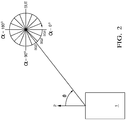
- FIG. 2 shows a plan view of a vehicle and a SUT, i.e. the horizontal plane as in a map.
- This figure shows a host (ego) vehicle 1 travelling in the direction shown by arrow 2 (this can be regarded as the trajectory of the vehicle).
- the SUT is shown as reference numeral 3.
- the line of sight from the vehicle to the SUT is shown by line 4, and the observation angle is given as ⁇ .
- the figure shows angular segmentation radially from the SUT; the SUT azimuthal angle (segmentation angle) given as ⁇ . This may be segmented into a number N of segments SG1, SG2, SG3, . and so on.
- As ⁇ changes the angle of sight of the vehicle from the SUT (segmentation angle) ⁇ will change correspondingly.
- the changes in radar parameters are determined as ⁇ and therefore as ⁇ changes.
- one or more parameters are measured and compared for two or more segments, as the line of sight falls within the appropriate segment.
- the above segmentation technique lends itself to a histogram approach used to determine how radar parameters vary with vehicle and SUT relative azimuthal angle.
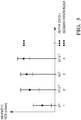
- Figure 3 shows a histogram showing inverse mapping of the mean (and standard deviation, std) values of the RCS against the angle ⁇ in terms of the segments shown in fig2 .
- the one or more of the following parameters may be determined: phase, polarization and signal-to-noise ratio. How these parameters vary with azimuthal angle ⁇ i.e. segmentation angle ⁇ , yields information on the quality of the landmark. The more there is variation of the parameters with said angles the less is the quality of the ST as a suitable landmark.
- the classification of a target may be carried out in two processing domains: on the detection level and on the tracker level.
- the features of the SUT that are extracted on the detection level are combined with the tracker-based features (collected over time or use a mapping approach) to provide the final classification result; to classify whether the SUT is a suitable landmark.
- detections based on the motion state may be filtered out and only stationary detections used.
- the elevation angle of SUT (if available) may be taken into consideration, because a scatterer on the ground is preferable as it causes no multipath reflections.
Priority Applications (3)
| Application Number | Priority Date | Filing Date | Title |
|---|---|---|---|
| EP17190576.3A EP3454079B1 (fr) | 2017-09-12 | 2017-09-12 | Procédé permettant de déterminer l'adaptabilité d'une cible radar en tant que repère de position |
| US16/106,377 US10830874B2 (en) | 2017-09-12 | 2018-08-21 | Method to determine the suitability of a radar target as a positional landmark |
| CN201811055834.7A CN109490874B (zh) | 2017-09-12 | 2018-09-11 | 确定雷达目标作为位置地标的适合性的方法 |
Applications Claiming Priority (1)
| Application Number | Priority Date | Filing Date | Title |
|---|---|---|---|
| EP17190576.3A EP3454079B1 (fr) | 2017-09-12 | 2017-09-12 | Procédé permettant de déterminer l'adaptabilité d'une cible radar en tant que repère de position |
Publications (2)
| Publication Number | Publication Date |
|---|---|
| EP3454079A1 true EP3454079A1 (fr) | 2019-03-13 |
| EP3454079B1 EP3454079B1 (fr) | 2023-11-01 |
Family
ID=59856452
Family Applications (1)
| Application Number | Title | Priority Date | Filing Date |
|---|---|---|---|
| EP17190576.3A Active EP3454079B1 (fr) | 2017-09-12 | 2017-09-12 | Procédé permettant de déterminer l'adaptabilité d'une cible radar en tant que repère de position |
Country Status (3)
| Country | Link |
|---|---|
| US (1) | US10830874B2 (fr) |
| EP (1) | EP3454079B1 (fr) |
| CN (1) | CN109490874B (fr) |
Cited By (9)
| Publication number | Priority date | Publication date | Assignee | Title |
|---|---|---|---|---|
| CN110456343A (zh) * | 2019-07-22 | 2019-11-15 | 深圳普捷利科技有限公司 | 一种基于fmcw毫米波雷达的即时定位方法及系统 |
| GB202101445D0 (en) | 2021-02-02 | 2021-03-17 | Aptiv Tech Ltd | Object detection with multiple ranges and resolutions |
| WO2021053620A1 (fr) * | 2019-09-18 | 2021-03-25 | Thales Canada Inc. | Procédé et système de localisation de véhicule à haute intégrité et détermination de vitesse |
| US11249171B2 (en) | 2018-06-28 | 2022-02-15 | Aptiv Technologies Limited | Method of determining an alignment error of an antenna and vehicle with an antenna and a detection device |
| EP4001962A1 (fr) | 2020-11-23 | 2022-05-25 | Aptiv Technologies Limited | Dispositif, procédé et programme de détermination d'espace libre |
| EP4047553A1 (fr) | 2021-02-19 | 2022-08-24 | Aptiv Technologies Limited | Compensation et décomposition de mouvement dans des réseaux neuronaux récurrents |
| EP4191274A1 (fr) | 2021-12-03 | 2023-06-07 | Aptiv Technologies Limited | Estimation de la hauteur d'un objet basée sur radar |
| EP4220083A1 (fr) | 2022-01-27 | 2023-08-02 | Aptiv Technologies Limited | Procédé de détermination d'un point d'intérêt et/ou d'un type de route dans une carte, et serveur en nuage et véhicule associés |
| US11719799B2 (en) | 2020-04-27 | 2023-08-08 | Aptiv Technologies Limited | Method for determining a collision free space |
Families Citing this family (6)
| Publication number | Priority date | Publication date | Assignee | Title |
|---|---|---|---|---|
| KR102090880B1 (ko) * | 2018-10-11 | 2020-03-18 | 한국과학기술원 | Fmcw 레이더에서의 누설 신호 감쇄 방법 및 그 레이더 시스템 |
| DE102019124850B4 (de) * | 2019-09-16 | 2021-08-12 | Infineon Technologies Ag | Phasenoptimierung für die verbesserte Detektion von Radarzielen |
| RU2717233C1 (ru) * | 2019-09-25 | 2020-03-19 | Российская Федерация, от имени которой выступает Государственная корпорация по атомной энергии "Росатом" (Госкорпорация "Росатом") | Способ определения дальности до поверхности земли |
| CN113033586B (zh) * | 2019-12-24 | 2024-04-16 | 大富科技(安徽)股份有限公司 | 目标识别方法及设备 |
| CN112014822B (zh) * | 2020-08-28 | 2024-04-09 | 北京川速微波科技有限公司 | 车载雷达测量数据识别方法、装置、介质和电子装置 |
| US20220206136A1 (en) * | 2020-12-31 | 2022-06-30 | Thales Canada Inc. | Method and system for high-integrity vehicle localization |
Citations (4)
| Publication number | Priority date | Publication date | Assignee | Title |
|---|---|---|---|---|
| DE102014011731A1 (de) * | 2014-08-06 | 2015-04-02 | Daimler Ag | Verfahren zum Betreiben eines Kraftfahrzeugs |
| DE102015208228A1 (de) * | 2015-05-05 | 2016-11-10 | Bayerische Motoren Werke Aktiengesellschaft | Diagnoseverfahren für einen Sichtsensor eines Fahrzeugs und Fahrzeug mit einem Sichtsensor |
| EP3144696A1 (fr) * | 2015-09-15 | 2017-03-22 | Delphi Technologies, Inc. | Système radar pour véhicule automatisé à catégorisation de cible basée sur le changement de phase |
| DE102016015405A1 (de) * | 2016-12-22 | 2017-07-06 | Daimler Ag | Umfassende Umgebungserfassung für einen Kraftwagen mittels Radar |
Family Cites Families (31)
| Publication number | Priority date | Publication date | Assignee | Title |
|---|---|---|---|---|
| DE2518120A1 (de) * | 1975-04-24 | 1976-11-04 | Daimler Benz Ag | Verkehrssystem, insbesondere oeffentliches personennahverkehrssystem |
| FR2657160B1 (fr) * | 1990-01-12 | 1992-05-07 | Aerospatiale | Systeme embarque pour determiner la position d'un vehicule aerien et ses applications. |
| WO1996007959A1 (fr) * | 1994-09-06 | 1996-03-14 | Siemens Aktiengesellschaft | Procede de determination de la position d'un point de repere dans la carte de l'environnement d'une unite automobile qui determine dynamiquement la distance qui la separe du point de repere |
| US6002983A (en) * | 1997-08-27 | 1999-12-14 | Delphi Technologies, Inc. | Angle extent estimation method for a motor vehicle object detection system |
| US7250901B2 (en) * | 2003-07-03 | 2007-07-31 | Navcom Technology Inc. | Synthetic aperture radar system and method for local positioning |
| US20050270228A1 (en) * | 2003-07-03 | 2005-12-08 | Stephens Scott A | Radar system for local positioning |
| US7315275B2 (en) * | 2003-07-03 | 2008-01-01 | Navcom Technology, Inc. | Positioning system with intentional multi-path signal |
| US7191056B2 (en) * | 2005-01-04 | 2007-03-13 | The Boeing Company | Precision landmark-aided navigation |
| US7826969B2 (en) * | 2006-12-21 | 2010-11-02 | Deere & Company | Determining position of a vehicle with reference to a landmark |
| US9651388B1 (en) * | 2007-10-25 | 2017-05-16 | Rockwell Collins, Inc. | System and method for improved simultaneous localization and mapping |
| US8155877B2 (en) * | 2007-11-29 | 2012-04-10 | Microsoft Corporation | Location-to-landmark |
| US20100076710A1 (en) * | 2008-09-19 | 2010-03-25 | Caterpillar Inc. | Machine sensor calibration system |
| US7840075B2 (en) * | 2009-01-26 | 2010-11-23 | Honeywell International, Inc. | Marine radar system with three-dimensional memory |
| US8340852B2 (en) * | 2009-04-29 | 2012-12-25 | Honeywell International Inc. | System and method for simultaneous localization and map building |
| US20110153338A1 (en) * | 2009-12-17 | 2011-06-23 | Noel Wayne Anderson | System and method for deploying portable landmarks |
| KR101663650B1 (ko) * | 2010-06-29 | 2016-10-07 | 삼성전자주식회사 | 거리 신호를 이용하여 위치를 인식하는 장치 및 방법 |
| MY158671A (en) * | 2011-04-21 | 2016-10-31 | Konecranes Global Corp | Techniques for positioning a vehicle |
| JP2012233743A (ja) * | 2011-04-28 | 2012-11-29 | Furuno Electric Co Ltd | 情報表示装置 |
| DE102012004396A1 (de) * | 2012-03-03 | 2013-09-05 | Volkswagen Aktiengesellschaft | Verfahren und Vorrichtung zum Erfassen von Objekten in einer Umgebung eines Fahrzeugs |
| US9037411B2 (en) * | 2012-05-11 | 2015-05-19 | Honeywell International Inc. | Systems and methods for landmark selection for navigation |
| DE102012224107A1 (de) * | 2012-12-20 | 2014-06-26 | Continental Teves Ag & Co. Ohg | Verfahren zum Bestimmen einer Referenzposition als Startposition für ein Trägheitsnavigationssystem |
| KR20160002178A (ko) * | 2014-06-30 | 2016-01-07 | 현대자동차주식회사 | 자차 위치 인식 장치 및 방법 |
| EP3032221B1 (fr) * | 2014-12-09 | 2022-03-30 | Volvo Car Corporation | Procédé et système pour améliorer la précision de données topographiques numériques utilisée par un véhicule |
| US20160377711A1 (en) * | 2015-06-26 | 2016-12-29 | Delphi Technologies, Inc. | Radar signal processing for automated vehicles |
| US9464914B1 (en) * | 2015-09-01 | 2016-10-11 | International Business Machines Corporation | Landmark navigation |
| US10817065B1 (en) * | 2015-10-06 | 2020-10-27 | Google Llc | Gesture recognition using multiple antenna |
| DE102016201250A1 (de) * | 2016-01-28 | 2017-08-03 | Conti Temic Microelectronic Gmbh | Verfahren und Vorrichtung zur Reichweitenbestimmung eines Sensors für ein Kraftfahrzeug |
| US10126141B2 (en) * | 2016-05-02 | 2018-11-13 | Google Llc | Systems and methods for using real-time imagery in navigation |
| TWI618017B (zh) * | 2016-07-15 | 2018-03-11 | Chunghwa Telecom Co Ltd | 結合生活行為分析與社群之地標推薦方法及其電腦程式產品 |
| US10697779B2 (en) * | 2017-04-21 | 2020-06-30 | X Development Llc | Landmark placement for localization |
| US10761541B2 (en) * | 2017-04-21 | 2020-09-01 | X Development Llc | Localization with negative mapping |
-
2017
- 2017-09-12 EP EP17190576.3A patent/EP3454079B1/fr active Active
-
2018
- 2018-08-21 US US16/106,377 patent/US10830874B2/en active Active
- 2018-09-11 CN CN201811055834.7A patent/CN109490874B/zh active Active
Patent Citations (4)
| Publication number | Priority date | Publication date | Assignee | Title |
|---|---|---|---|---|
| DE102014011731A1 (de) * | 2014-08-06 | 2015-04-02 | Daimler Ag | Verfahren zum Betreiben eines Kraftfahrzeugs |
| DE102015208228A1 (de) * | 2015-05-05 | 2016-11-10 | Bayerische Motoren Werke Aktiengesellschaft | Diagnoseverfahren für einen Sichtsensor eines Fahrzeugs und Fahrzeug mit einem Sichtsensor |
| EP3144696A1 (fr) * | 2015-09-15 | 2017-03-22 | Delphi Technologies, Inc. | Système radar pour véhicule automatisé à catégorisation de cible basée sur le changement de phase |
| DE102016015405A1 (de) * | 2016-12-22 | 2017-07-06 | Daimler Ag | Umfassende Umgebungserfassung für einen Kraftwagen mittels Radar |
Cited By (13)
| Publication number | Priority date | Publication date | Assignee | Title |
|---|---|---|---|---|
| US11249171B2 (en) | 2018-06-28 | 2022-02-15 | Aptiv Technologies Limited | Method of determining an alignment error of an antenna and vehicle with an antenna and a detection device |
| CN110456343B (zh) * | 2019-07-22 | 2021-05-28 | 深圳普捷利科技有限公司 | 一种基于fmcw毫米波雷达的即时定位方法及系统 |
| CN110456343A (zh) * | 2019-07-22 | 2019-11-15 | 深圳普捷利科技有限公司 | 一种基于fmcw毫米波雷达的即时定位方法及系统 |
| US11754702B2 (en) | 2019-09-18 | 2023-09-12 | Thales Canada Inc. | Method and system for high-integrity vehicle localization and speed determination |
| WO2021053620A1 (fr) * | 2019-09-18 | 2021-03-25 | Thales Canada Inc. | Procédé et système de localisation de véhicule à haute intégrité et détermination de vitesse |
| US11719799B2 (en) | 2020-04-27 | 2023-08-08 | Aptiv Technologies Limited | Method for determining a collision free space |
| EP4001962A1 (fr) | 2020-11-23 | 2022-05-25 | Aptiv Technologies Limited | Dispositif, procédé et programme de détermination d'espace libre |
| EP4036595A1 (fr) | 2021-02-02 | 2022-08-03 | Aptiv Technologies Limited | Détection d'objet avec plusieurs plages et résolutions |
| GB2603476A (en) | 2021-02-02 | 2022-08-10 | Aptiv Tech Ltd | Object detection with multiple ranges and resolutions |
| GB202101445D0 (en) | 2021-02-02 | 2021-03-17 | Aptiv Tech Ltd | Object detection with multiple ranges and resolutions |
| EP4047553A1 (fr) | 2021-02-19 | 2022-08-24 | Aptiv Technologies Limited | Compensation et décomposition de mouvement dans des réseaux neuronaux récurrents |
| EP4191274A1 (fr) | 2021-12-03 | 2023-06-07 | Aptiv Technologies Limited | Estimation de la hauteur d'un objet basée sur radar |
| EP4220083A1 (fr) | 2022-01-27 | 2023-08-02 | Aptiv Technologies Limited | Procédé de détermination d'un point d'intérêt et/ou d'un type de route dans une carte, et serveur en nuage et véhicule associés |
Also Published As
| Publication number | Publication date |
|---|---|
| EP3454079B1 (fr) | 2023-11-01 |
| CN109490874A (zh) | 2019-03-19 |
| US20200319300A1 (en) | 2020-10-08 |
| US10830874B2 (en) | 2020-11-10 |
| CN109490874B (zh) | 2023-06-06 |
Similar Documents
| Publication | Publication Date | Title |
|---|---|---|
| US10830874B2 (en) | Method to determine the suitability of a radar target as a positional landmark | |
| EP3546978B1 (fr) | Procédé permettant de tester un objet cible comme centre de diffusion à point unique | |
| CN105445734B (zh) | 具有基于相位的多目标检测的雷达系统 | |
| US9470777B2 (en) | Radar system for automated vehicle with phase change based target catagorization | |
| EP3663790A1 (fr) | Procédé et appareil de traitement de données radar | |
| Gierull et al. | Two-step detector for RADARSAT-2's experimental GMTI mode | |
| US10989809B2 (en) | Single scatterer test using amplitude and a plurality of receive elements | |
| US10317520B2 (en) | Radar system | |
| EP1485729B1 (fr) | Systeme et procede de calcul et de reconnaissance de signature cible | |
| JP2021536575A (ja) | レーダセンサにおける角度測定誤差を検出する方法 | |
| US5748140A (en) | System for tracking radar targets in background clutter | |
| EP3144696A1 (fr) | Système radar pour véhicule automatisé à catégorisation de cible basée sur le changement de phase | |
| EP3454080B1 (fr) | Test de diffuseur unique au moyen d'un changement de la phase | |
| US6982668B1 (en) | Tangential velocity measurement using interferometric MTI radar | |
| Joshi et al. | Direction-of-arrival angle and position estimation for extended targets using multichannel airborne radar data | |
| US11333754B2 (en) | Detection of parking row orientation | |
| US6816109B1 (en) | Method for automatic association of moving target indications from entities traveling along known route | |
| CN114594466A (zh) | 用于确定目标的自有速度估计值和角度估计值的方法 | |
| Steiner et al. | Cooperative target detection in a network of single-channel radar sensors | |
| Rohling | Development milestones in 24 GHz automotive radar systems | |
| EP3483629B1 (fr) | Détection d'une rangée de stationnement à l'aide d'un système de radar de véhicule | |
| Zaumseil et al. | Radar-based near field environment perception using back projection algorithm | |
| Laribi et al. | Vertical digital beamforming versus vertical Doppler Beam Sharpening | |
| Sjögren et al. | Change Detection for Monostatic Pursuit SAR GMTI—Theories and Experimental Results | |
| WO2023129094A1 (fr) | Système de détection de drone distribué basé sur un décalage doppler |
Legal Events
| Date | Code | Title | Description |
|---|---|---|---|
| PUAI | Public reference made under article 153(3) epc to a published international application that has entered the european phase |
Free format text: ORIGINAL CODE: 0009012 |
|
| STAA | Information on the status of an ep patent application or granted ep patent |
Free format text: STATUS: THE APPLICATION HAS BEEN PUBLISHED |
|
| AK | Designated contracting states |
Kind code of ref document: A1 Designated state(s): AL AT BE BG CH CY CZ DE DK EE ES FI FR GB GR HR HU IE IS IT LI LT LU LV MC MK MT NL NO PL PT RO RS SE SI SK SM TR |
|
| AX | Request for extension of the european patent |
Extension state: BA ME |
|
| STAA | Information on the status of an ep patent application or granted ep patent |
Free format text: STATUS: REQUEST FOR EXAMINATION WAS MADE |
|
| 17P | Request for examination filed |
Effective date: 20190913 |
|
| RBV | Designated contracting states (corrected) |
Designated state(s): AL AT BE BG CH CY CZ DE DK EE ES FI FR GB GR HR HU IE IS IT LI LT LU LV MC MK MT NL NO PL PT RO RS SE SI SK SM TR |
|
| STAA | Information on the status of an ep patent application or granted ep patent |
Free format text: STATUS: EXAMINATION IS IN PROGRESS |
|
| 17Q | First examination report despatched |
Effective date: 20210211 |
|
| STAA | Information on the status of an ep patent application or granted ep patent |
Free format text: STATUS: EXAMINATION IS IN PROGRESS |
|
| RAP3 | Party data changed (applicant data changed or rights of an application transferred) |
Owner name: APTIV TECHNOLOGIES LIMITED |
|
| GRAP | Despatch of communication of intention to grant a patent |
Free format text: ORIGINAL CODE: EPIDOSNIGR1 |
|
| STAA | Information on the status of an ep patent application or granted ep patent |
Free format text: STATUS: GRANT OF PATENT IS INTENDED |
|
| RIC1 | Information provided on ipc code assigned before grant |
Ipc: G01S 13/72 20060101ALN20230426BHEP Ipc: G01S 13/58 20060101ALN20230426BHEP Ipc: G01S 13/931 20200101ALI20230426BHEP Ipc: G01S 13/42 20060101ALI20230426BHEP Ipc: G01S 7/41 20060101AFI20230426BHEP |
|
| RIC1 | Information provided on ipc code assigned before grant |
Ipc: G01S 13/72 20060101ALN20230428BHEP Ipc: G01S 13/58 20060101ALN20230428BHEP Ipc: G01S 13/931 20200101ALI20230428BHEP Ipc: G01S 13/42 20060101ALI20230428BHEP Ipc: G01S 7/41 20060101AFI20230428BHEP |
|
| INTG | Intention to grant announced |
Effective date: 20230524 |
|
| GRAS | Grant fee paid |
Free format text: ORIGINAL CODE: EPIDOSNIGR3 |
|
| GRAA | (expected) grant |
Free format text: ORIGINAL CODE: 0009210 |
|
| STAA | Information on the status of an ep patent application or granted ep patent |
Free format text: STATUS: THE PATENT HAS BEEN GRANTED |
|
| AK | Designated contracting states |
Kind code of ref document: B1 Designated state(s): AL AT BE BG CH CY CZ DE DK EE ES FI FR GB GR HR HU IE IS IT LI LT LU LV MC MK MT NL NO PL PT RO RS SE SI SK SM TR |
|
| REG | Reference to a national code |
Ref country code: GB Ref legal event code: FG4D |
|
| REG | Reference to a national code |
Ref country code: CH Ref legal event code: EP |
|
| REG | Reference to a national code |
Ref country code: IE Ref legal event code: FG4D |
|
| REG | Reference to a national code |
Ref country code: DE Ref legal event code: R096 Ref document number: 602017075928 Country of ref document: DE |
|
| P01 | Opt-out of the competence of the unified patent court (upc) registered |
Effective date: 20231024 |
|
| REG | Reference to a national code |
Ref country code: LT Ref legal event code: MG9D |
|
| REG | Reference to a national code |
Ref country code: NL Ref legal event code: MP Effective date: 20231101 |
|
| PG25 | Lapsed in a contracting state [announced via postgrant information from national office to epo] |
Ref country code: GR Free format text: LAPSE BECAUSE OF FAILURE TO SUBMIT A TRANSLATION OF THE DESCRIPTION OR TO PAY THE FEE WITHIN THE PRESCRIBED TIME-LIMIT Effective date: 20240202 |
|
| PG25 | Lapsed in a contracting state [announced via postgrant information from national office to epo] |
Ref country code: IS Free format text: LAPSE BECAUSE OF FAILURE TO SUBMIT A TRANSLATION OF THE DESCRIPTION OR TO PAY THE FEE WITHIN THE PRESCRIBED TIME-LIMIT Effective date: 20240301 |
|
| PG25 | Lapsed in a contracting state [announced via postgrant information from national office to epo] |
Ref country code: LT Free format text: LAPSE BECAUSE OF FAILURE TO SUBMIT A TRANSLATION OF THE DESCRIPTION OR TO PAY THE FEE WITHIN THE PRESCRIBED TIME-LIMIT Effective date: 20231101 |
|
| REG | Reference to a national code |
Ref country code: AT Ref legal event code: MK05 Ref document number: 1627823 Country of ref document: AT Kind code of ref document: T Effective date: 20231101 |
|
| PG25 | Lapsed in a contracting state [announced via postgrant information from national office to epo] |
Ref country code: NL Free format text: LAPSE BECAUSE OF FAILURE TO SUBMIT A TRANSLATION OF THE DESCRIPTION OR TO PAY THE FEE WITHIN THE PRESCRIBED TIME-LIMIT Effective date: 20231101 |