EP3454005A1 - Method for determining accumulation of foreign matter on green tire - Google Patents
Method for determining accumulation of foreign matter on green tire Download PDFInfo
- Publication number
- EP3454005A1 EP3454005A1 EP17806223.8A EP17806223A EP3454005A1 EP 3454005 A1 EP3454005 A1 EP 3454005A1 EP 17806223 A EP17806223 A EP 17806223A EP 3454005 A1 EP3454005 A1 EP 3454005A1
- Authority
- EP
- European Patent Office
- Prior art keywords
- data
- examination
- foreign matter
- dimensional
- green tire
- Prior art date
- Legal status (The legal status is an assumption and is not a legal conclusion. Google has not performed a legal analysis and makes no representation as to the accuracy of the status listed.)
- Granted
Links
Images


Classifications
-
- B—PERFORMING OPERATIONS; TRANSPORTING
- B29—WORKING OF PLASTICS; WORKING OF SUBSTANCES IN A PLASTIC STATE IN GENERAL
- B29D—PRODUCING PARTICULAR ARTICLES FROM PLASTICS OR FROM SUBSTANCES IN A PLASTIC STATE
- B29D30/00—Producing pneumatic or solid tyres or parts thereof
- B29D30/0061—Accessories, details or auxiliary operations not otherwise provided for
-
- B—PERFORMING OPERATIONS; TRANSPORTING
- B29—WORKING OF PLASTICS; WORKING OF SUBSTANCES IN A PLASTIC STATE IN GENERAL
- B29D—PRODUCING PARTICULAR ARTICLES FROM PLASTICS OR FROM SUBSTANCES IN A PLASTIC STATE
- B29D30/00—Producing pneumatic or solid tyres or parts thereof
- B29D30/06—Pneumatic tyres or parts thereof (e.g. produced by casting, moulding, compression moulding, injection moulding, centrifugal casting)
- B29D30/52—Unvulcanised treads, e.g. on used tyres; Retreading
- B29D30/58—Applying bands of rubber treads, i.e. applying camel backs
- B29D30/60—Applying bands of rubber treads, i.e. applying camel backs by winding narrow strips
-
- G—PHYSICS
- G01—MEASURING; TESTING
- G01B—MEASURING LENGTH, THICKNESS OR SIMILAR LINEAR DIMENSIONS; MEASURING ANGLES; MEASURING AREAS; MEASURING IRREGULARITIES OF SURFACES OR CONTOURS
- G01B11/00—Measuring arrangements characterised by the use of optical techniques
- G01B11/24—Measuring arrangements characterised by the use of optical techniques for measuring contours or curvatures
-
- G—PHYSICS
- G01—MEASURING; TESTING
- G01B—MEASURING LENGTH, THICKNESS OR SIMILAR LINEAR DIMENSIONS; MEASURING ANGLES; MEASURING AREAS; MEASURING IRREGULARITIES OF SURFACES OR CONTOURS
- G01B11/00—Measuring arrangements characterised by the use of optical techniques
- G01B11/24—Measuring arrangements characterised by the use of optical techniques for measuring contours or curvatures
- G01B11/25—Measuring arrangements characterised by the use of optical techniques for measuring contours or curvatures by projecting a pattern, e.g. one or more lines, moiré fringes on the object
- G01B11/2518—Projection by scanning of the object
- G01B11/2522—Projection by scanning of the object the position of the object changing and being recorded
-
- G—PHYSICS
- G01—MEASURING; TESTING
- G01B—MEASURING LENGTH, THICKNESS OR SIMILAR LINEAR DIMENSIONS; MEASURING ANGLES; MEASURING AREAS; MEASURING IRREGULARITIES OF SURFACES OR CONTOURS
- G01B11/00—Measuring arrangements characterised by the use of optical techniques
- G01B11/30—Measuring arrangements characterised by the use of optical techniques for measuring roughness or irregularity of surfaces
-
- G—PHYSICS
- G01—MEASURING; TESTING
- G01N—INVESTIGATING OR ANALYSING MATERIALS BY DETERMINING THEIR CHEMICAL OR PHYSICAL PROPERTIES
- G01N21/00—Investigating or analysing materials by the use of optical means, i.e. using sub-millimetre waves, infrared, visible or ultraviolet light
- G01N21/84—Systems specially adapted for particular applications
- G01N21/88—Investigating the presence of flaws or contamination
- G01N21/8851—Scan or image signal processing specially adapted therefor, e.g. for scan signal adjustment, for detecting different kinds of defects, for compensating for structures, markings, edges
-
- G—PHYSICS
- G01—MEASURING; TESTING
- G01N—INVESTIGATING OR ANALYSING MATERIALS BY DETERMINING THEIR CHEMICAL OR PHYSICAL PROPERTIES
- G01N21/00—Investigating or analysing materials by the use of optical means, i.e. using sub-millimetre waves, infrared, visible or ultraviolet light
- G01N21/84—Systems specially adapted for particular applications
- G01N21/88—Investigating the presence of flaws or contamination
- G01N21/94—Investigating contamination, e.g. dust
-
- G—PHYSICS
- G06—COMPUTING OR CALCULATING; COUNTING
- G06T—IMAGE DATA PROCESSING OR GENERATION, IN GENERAL
- G06T17/00—Three-dimensional [3D] modelling for computer graphics
-
- G—PHYSICS
- G06—COMPUTING OR CALCULATING; COUNTING
- G06T—IMAGE DATA PROCESSING OR GENERATION, IN GENERAL
- G06T7/00—Image analysis
- G06T7/0002—Inspection of images, e.g. flaw detection
- G06T7/0004—Industrial image inspection
-
- B—PERFORMING OPERATIONS; TRANSPORTING
- B29—WORKING OF PLASTICS; WORKING OF SUBSTANCES IN A PLASTIC STATE IN GENERAL
- B29D—PRODUCING PARTICULAR ARTICLES FROM PLASTICS OR FROM SUBSTANCES IN A PLASTIC STATE
- B29D30/00—Producing pneumatic or solid tyres or parts thereof
- B29D30/0061—Accessories, details or auxiliary operations not otherwise provided for
- B29D2030/0066—Tyre quality control during manufacturing
-
- G—PHYSICS
- G06—COMPUTING OR CALCULATING; COUNTING
- G06T—IMAGE DATA PROCESSING OR GENERATION, IN GENERAL
- G06T2207/00—Indexing scheme for image analysis or image enhancement
- G06T2207/10—Image acquisition modality
- G06T2207/10016—Video; Image sequence
Definitions
- the present invention relates to a determining method for determining whether a foreign matter is adhered on a green tire formed by a strip winding method.
- the rubber strip has a tendency to bunch up together into a mass in the winding start end and the winding finishing end of the rubber strip.
- the outer surface of a green tire has a high tackiness. Therefore, there is a tendency that cut pieces of the rubber strip cut out during forming the green tire adhere onto the outer surface.
- a green tire is vulcanized together with foreign matters such as the mass and cut pieces of the rubber strip remained adhered, there is a possibility that the tire quality is lowered.
- the present invention is a determining method for determining the adhesion of a foreign matter on the outer surface of a green tire which outer surface is formed by spirally winding a rubber strip, comprises a raw data acquiring step in which an examination surface of the outer surface of the green tire is scanned in the circumferential direction with a two-dimensional displacement sensor, and a raw three-dimensional data D0 of the examination surface is created, an averaging processing step in which, by averaging processing distance data z in the raw three-dimensional data D0, processed three-dimensional data D1 are obtained, an imaging step in which distance data z in the processed three-dimensional data D1 are each binarized at a threshold, and an image is created, a determining step in which, based on the data about the created image, whether a foreign matter is adhered is determined, wherein in the raw data acquiring step, the green tire is rotated about its axis, and the two-dimensional displacement sensor irradiates the examination surface of the rotating green tire with a sensor light which is linear and
- the averaging processing is made on the raw three-dimensional data D0 about the examination surface obtained from the rotating green tire and the two-dimensional displacement sensor.
- the width wx in the x direction and the width wy in the circumferential direction of the range on which the averaging processing is made are set to be larger than the spiral pitch of the rubber strip and less than the width of the rubber strip.
- the distance data z in the averaged processed three-dimensional data D1 are binarized at the threshold, and from the binarized three-dimensional processed data D2, the image is created. Therefore, it is possible to visualize and capture the size of the foreign matter, and it becomes possible to easily determine the adhesion of the foreign matter.
- the method for determining the adhesion of a foreign matter on a green tire comprises a raw data acquiring step Sa, an averaging processing step Sb, an imaging step Sc, and a determining step Sd.
- the method for determining the adhesion of a foreign matter determines the presence or absence of foreign matters J adhered to an outer surface Ts of a green tire T.
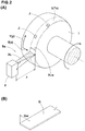
- At least one of rubber components constituting the outer skin of the tire is formed by spirally winding an unvulcanized rubber strip G (shown in Figure 2 (B) ). Therefore, in the outer surface of the tire formed from the rubber strip G, fine stepped unevenness 10 (shown in Figure 4 (A) ) is formed.
- an examination surface 3 of the outer surface Ts of the green tire T is scanned in the circumferential direction Y by the use of a two-dimensional displacement sensor 2. Specifically, the green tire T is rotated about its axis. The two-dimensional displacement sensor 2 irradiates the examination surface 3 of the rotating green tire T with a sensor light 2L which is linear and elongate in the X direction perpendicular to the circumferential direction Y.
- the two-dimensional displacement sensor 2 is a so-called laser displacement sensor radiating a line-shaped sensor light 2L, and commercially available various sensors can be used.
- a two-dimensional displacement sensor 2 whose irradiation width 2Lw is for example 60 to 80 mm is used.
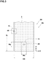
- averaging processing step Sb as shown conceptually in Figure 3 , with respect to the raw three-dimensional data D0, for each of the distance data z, an averaging process is made over a range K having a width Wx in the X direction and a width wy in the circumferential direction, and thereby, processed three-dimensional data D1 are obtained.
- the raw three-dimensional data D0 are a set of data pieces d shown as dots in Figure 3 .
- the examination surface 3 has a width 3w in the X direction of 70 mm, and a length 3L in the circumferential direction Y of 2000 mm, and the data about this examination surface 3 are obtained at intervals of 0.0875 mm in the X direction, and intervals of 0.125 mm in the circumferential direction Y.
- the raw three-dimensional data D0 in this example are a set of 800x16000 data pieces d.
- the distance datum z of each data piece d is expressed as a height of the dot (not shown).
- the averaging processing there are averaged the distance data z of all the data pieces d (including a data piece dO) positioned within a range K centered on the data piece dO in the plurality of the data pieces d.
- the distance datum z in the data piece d0 before averaged is replaced by the averaged distance datum z1.
- This is performed on each of the data pieces d in the raw three-dimensional data D0.
- processed three-dimensional data D1 are obtained. The same is applied to the data pieces d0 positioned at both ends in the X direction.
- the width wx in the x direction and the width wy in the circumferential direction of the range K are set to be large than the spiral pitch P (shown in Figure 4 (A) ) of the rubber strip G and smaller than the width Gw (shown in Figure 2 (B) ) of the rubber strip G.
- the spiral pitch P is varied, the minimum spiral pitch P is applied.
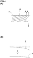
- the unevenness 10 of the examination surface 3 due to the spiral winding of the rubber strip G can be eliminated and smoothed as shown in Figure 4 (A) .
- the smoothed examination surface 3 can be more flattened as shown in Figure 4 (B) .
- the outer surface Ts of the green tire T is divided into, for example, seven sections, an examination surface 3A on a tread center side, examination surfaces 3B, 3B on tread shoulder sides, examination surfaces 3C, 3C on sidewall upper sides, and examination surfaces 3D, 3D on sidewall lower sides as shown in Figure 6 . Then, sets of the raw three-dimensional data D0 of the examination surfaces 3A to 3D are respectively acquired by separate two-dimensional displacement sensors 2. That is, it is preferable that the outer surface Ts of the green tire T is divided into a plurality of the examination surfaces 3 in which the profile change becomes small. It is preferable that the number of divisions is 7 or more.
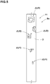
- each of the distance data z of the processed three-dimensional data D1 is binarized at a threshold. Then, from the binarized three-dimensional processed data D2, an image is created. Thus, it is possible to obtain image data 11 for example as shown in Figure 5 .
- the creating of the image can be made by converting the binarized three-dimensional processed data D2 into pixel data.
- the foreign matters J are expressed by a difference of color including, for example, chroma, hue and brightness, while hiding the unevenness 10 due to the rubber strip G, and the sizes are visualized to be captured.
- the threshold is at least 200% of the thickness of the rubber strip G.
- the determining step Sd based on the image data 11, whether the foreign matter J is adhered, is determined.
- the determination can be made through visual observation by an inspector. But, it is preferable that the determination is made automatically through an image analysis of the pixel area and the like of the appearing portion of the foreign material J.
- a tire outer skin of a green tire T was formed. Then, by applying a foreign matter J1 (10 mm x 10 mm x 2.0 mm), a foreign matter J2 (20 mm x 20 mm x 2.0 mm) and a foreign matter J3 (30 mm x 30 mm x 2.0 mm) onto an examination surface 3B on the tread shoulder side of the green tire T, a sample tire was prepared. And the image data 11 shown in Figure 5 was obtained by the method for determining the adhesion of a foreign matter according to the present invention.
Landscapes
- Engineering & Computer Science (AREA)
- Physics & Mathematics (AREA)
- General Physics & Mathematics (AREA)
- Computer Vision & Pattern Recognition (AREA)
- Mechanical Engineering (AREA)
- Immunology (AREA)
- Pathology (AREA)
- Health & Medical Sciences (AREA)
- Life Sciences & Earth Sciences (AREA)
- Chemical & Material Sciences (AREA)
- Analytical Chemistry (AREA)
- Biochemistry (AREA)
- General Health & Medical Sciences (AREA)
- Theoretical Computer Science (AREA)
- Geometry (AREA)
- Software Systems (AREA)
- Computer Graphics (AREA)
- Signal Processing (AREA)
- Quality & Reliability (AREA)
- Length Measuring Devices By Optical Means (AREA)
- Tyre Moulding (AREA)
- Tires In General (AREA)
Abstract
Description
- The present invention relates to a determining method for determining whether a foreign matter is adhered on a green tire formed by a strip winding method.
- Recently, there has been proposed a so-called strip wind method for forming constructional rubber components constituting a tire outer skin, for example, a tread rubber, a sidewall rubber and the like, by spirally winding an unvulcanized rubber strip. (cf. Patent Documents 1, 2)
- In the strip winding method, the rubber strip has a tendency to bunch up together into a mass in the winding start end and the winding finishing end of the rubber strip. The outer surface of a green tire has a high tackiness. Therefore, there is a tendency that cut pieces of the rubber strip cut out during forming the green tire adhere onto the outer surface. When a green tire is vulcanized together with foreign matters such as the mass and cut pieces of the rubber strip remained adhered, there is a possibility that the tire quality is lowered.
- It is however difficult to discriminate foreign matters by the use of a displacement sensor since the outer surface of the green tire has fine step-like unevenness due to the spiral winding of the rubber strip. Therefore, conventionally, the discrimination of the foreign matters is made through visual observation by an inspector. Thus, the reliability is low, and the work efficiency of the inspection becomes low.
-
- Patent Document 1: Japanese Patent Application Publication No.
2008-284815 - Patent Document 2: Japanese Patent Application Publication No.
2015-229438 - In the present invention, it is a problem to provide a method for determining the adhesion of a foreign matter on a green tire which can reliably and efficiently determine whether foreign matters such as mass and cut pieces of a rubber strip are adhered on a green tire formed by a strip winding method.
- The present invention is a determining method for determining the adhesion of a foreign matter on the outer surface of a green tire which outer surface is formed by spirally winding a rubber strip, comprises
a raw data acquiring step in which an examination surface of the outer surface of the green tire is scanned in the circumferential direction with a two-dimensional displacement sensor, and a raw three-dimensional data D0 of the examination surface is created,
an averaging processing step in which, by averaging processing distance data z in the raw three-dimensional data D0, processed three-dimensional data D1 are obtained,
an imaging step in which distance data z in the processed three-dimensional data D1 are each binarized at a threshold, and an image is created,
a determining step in which, based on the data about the created image, whether a foreign matter is adhered is determined, wherein
in the raw data acquiring step,
the green tire is rotated about its axis, and
the two-dimensional displacement sensor irradiates the examination surface of the rotating green tire with a sensor light which is linear and elongate in X direction perpendicular to the circumferential direction, thereby,
the raw three-dimensional data D0 made up of position data x in the X direction, position data y in the circumferential direction, and the distance data z from the two-dimensional displacement sensor to the examination surface, are created,
in the averaging processing step, with respect to the raw three-dimensional data D0, for each of the distance data z, the averaging process is made over a range having a width Wx in the X direction and a width wy in the circumferential direction, thereby, processed three-dimensional data D1 are obtained, wherein
each of the width wx and the width wy is larger than a spiral pitch of the rubber strip and is smaller than the width of the rubber strip. - As described above, in the present invention, the averaging processing is made on the raw three-dimensional data D0 about the examination surface obtained from the rotating green tire and the two-dimensional displacement sensor.
- The width wx in the x direction and the width wy in the circumferential direction of the range on which the averaging processing is made, are set to be larger than the spiral pitch of the rubber strip and less than the width of the rubber strip. Thereby, the fine stepped unevenness due to the spiral winding of the rubber strip can be eliminated and smoothed. Further, it is possible to flatten the examination surface.
- Further, the distance data z in the averaged processed three-dimensional data D1 are binarized at the threshold, and from the binarized three-dimensional processed data D2, the image is created. Therefore, it is possible to visualize and capture the size of the foreign matter, and it becomes possible to easily determine the adhesion of the foreign matter.
-
- [
Figure 1 ] A flowchart of the method for determining the adhesion of a foreign matter on a green tire according to the present invention. - [
Figure 2 ]- (A) is a perspective view conceptually showing the raw data acquiring step,
- (B) is a perspective view conceptually showing the rubber strip.
- [
Figure 3 ] A diagram conceptually showing the averaging processing step. - [
Figure 4 ] (A), (B) are diagrams conceptually showing the effect of the averaging processing step. - [
Figure 5 ] An image of the three-dimensional processed data D2 created by the imaging step. - [
Figure 6 ] A sectional view showing an example of sections of the outer surface of the green tire. - Hereinafter, an embodiment of the present invention will be described in detail.
- As shown in
Figure 1 , the method for determining the adhesion of a foreign matter on a green tire according to the present invention comprises a raw data acquiring step Sa, an averaging processing step Sb, an imaging step Sc, and a determining step Sd.
As shown inFigure 2 (A) , the method for determining the adhesion of a foreign matter determines the presence or absence of foreign matters J adhered to an outer surface Ts of a green tire T. - In the green tire T, at least one of rubber components constituting the outer skin of the tire, for example, a tread rubber, a sidewall rubber and the like, is formed by spirally winding an unvulcanized rubber strip G (shown in
Figure 2 (B) ). Therefore, in the outer surface of the tire formed from the rubber strip G, fine stepped unevenness 10 (shown inFigure 4 (A) ) is formed. - In the raw data acquiring step Sa, as shown in
Figure 2 (A) , anexamination surface 3 of the outer surface Ts of the green tire T is scanned in the circumferential direction Y by the use of a two-dimensional displacement sensor 2. Specifically, the green tire T is rotated about its axis. The two-dimensional displacement sensor 2 irradiates theexamination surface 3 of the rotating green tire T with asensor light 2L which is linear and elongate in the X direction perpendicular to the circumferential direction Y. - Thereby, there is created raw three-dimensional data D0 about the
examination surface 3 which consist of position data x in the X direction, position data y in the circumferential direction Y, and distance data z from the two-dimensional displacement sensor 2 to theexamination surface 3. The two-dimensional displacement sensor 2 is a so-called laser displacement sensor radiating a line-shaped sensor light 2L, and commercially available various sensors can be used. In this example, a two-dimensional displacement sensor 2 whose irradiation width 2Lw is for example 60 to 80 mm is used. - In the averaging processing step Sb, as shown conceptually in
Figure 3 , with respect to the raw three-dimensional data D0, for each of the distance data z, an averaging process is made over a range K having a width Wx in the X direction and a width wy in the circumferential direction, and thereby, processed three-dimensional data D1 are obtained. - The raw three-dimensional data D0 are a set of data pieces d shown as dots in
Figure 3 .
In this example, theexamination surface 3 has a width 3w in the X direction of 70 mm, and alength 3L in the circumferential direction Y of 2000 mm, and
the data about thisexamination surface 3 are obtained at intervals of 0.0875 mm in the X direction, and intervals of 0.125 mm in the circumferential direction Y.
Accordingly, the raw three-dimensional data D0 in this example are a set of 800x16000 data pieces d.
InFigure 3 , the distance datum z of each data piece d is expressed as a height of the dot (not shown). - In the averaging processing, there are averaged the distance data z of all the data pieces d (including a data piece dO) positioned within a range K centered on the data piece dO in the plurality of the data pieces d.
The distance datum z in the data piece d0 before averaged is replaced by the averaged distance datum z1.
This is performed on each of the data pieces d in the raw three-dimensional data D0.
Thereby, processed three-dimensional data D1 are obtained. The same is applied to the data pieces d0 positioned at both ends in the X direction. - The width wx in the x direction and the width wy in the circumferential direction of the range K are set to be large than the spiral pitch P (shown in
Figure 4 (A) ) of the rubber strip G and smaller than the width Gw (shown inFigure 2 (B) ) of the rubber strip G. when the spiral pitch P is varied, the minimum spiral pitch P is applied.
Thereby, theunevenness 10 of theexamination surface 3 due to the spiral winding of the rubber strip G can be eliminated and smoothed as shown inFigure 4 (A) .
Further, the smoothedexamination surface 3 can be more flattened as shown inFigure 4 (B) . In order to flatten, it is preferred that the outer surface Ts of the green tire T is divided into, for example, seven sections, anexamination surface 3A on a tread center side, examination surfaces 3B, 3B on tread shoulder sides, examination surfaces 3C, 3C on sidewall upper sides, andexamination surfaces Figure 6 . Then, sets of the raw three-dimensional data D0 of the examination surfaces 3A to 3D are respectively acquired by separate two-dimensional displacement sensors 2. That is, it is preferable that the outer surface Ts of the green tire T is divided into a plurality of the examination surfaces 3 in which the profile change becomes small. It is preferable that the number of divisions is 7 or more. - In the imaging step Sc, each of the distance data z of the processed three-dimensional data D1 is binarized at a threshold. Then, from the binarized three-dimensional processed data D2, an image is created. Thus, it is possible to obtain
image data 11 for example as shown inFigure 5 . The creating of the image can be made by converting the binarized three-dimensional processed data D2 into pixel data. - In the
image data 11, the foreign matters J are expressed by a difference of color including, for example, chroma, hue and brightness, while hiding theunevenness 10 due to the rubber strip G, and the sizes are visualized to be captured. Preferably, the threshold is at least 200% of the thickness of the rubber strip G.
By adjusting the width wx and the width wy, the size of the foreign matter J appearing can be adjusted. - In the determining step Sd, based on the
image data 11, whether the foreign matter J is adhered, is determined. The determination can be made through visual observation by an inspector. But, it is preferable that the determination is made automatically through an image analysis of the pixel area and the like of the appearing portion of the foreign material J. - while detailed description has been made of an especially preferable embodiment of the present invention, the present invention can be embodied in various forms without being limited to the illustrated embodiment.
- Using a rubber strip G, a tire outer skin of a green tire T was formed. Then, by applying a foreign matter J1 (10 mm x 10 mm x 2.0 mm), a foreign matter J2 (20 mm x 20 mm x 2.0 mm) and a foreign matter J3 (30 mm x 30 mm x 2.0 mm) onto an
examination surface 3B on the tread shoulder side of the green tire T, a sample tire was prepared. And theimage data 11 shown inFigure 5 was obtained by the method for determining the adhesion of a foreign matter according to the present invention. -
- rubber strip G: width Gw = 23 mm, thickness = 1.0 mm
- two-dimensional displacement sensor: LJ-V7200 manufactured by Keyence Corporation Ltd.
- laser beam irradiation width: 70 mm
- resolution: X direction 0.0875 mm (70 mm / 800 points), circumferential direction Y 0.125 mm (2000mm / 16000 points) averaging processed range K: width Wx = 5 mm, width wy = 5 mm
- It was possible to obtain the
image data 11 as shown inFigure 5 in which the foreign matters J1 to J3 could be identified. -
- 2
- two-dimensional displacement sensor
- 2L
- sensor light
- 3
- examination surface
- G
- rubber strip
- J
- foreign matter
- K
- range
- P
- spiral pitch
- Sa
- raw data acquiring step
- Sb
- averaging process step
- Sc
- imaging step
- Sd
- determining step
- T
- green tire
Claims (5)
- A method for determining the adhesion of a foreign matter which is a determining method for determining whether a foreign matter is adhered on an outer surface of a green tire which outer surface is formed by spirally winding a rubber strip, comprising:a raw data acquiring step in which an examination surface of the outer surface of the green tire is scanned in the circumferential direction with a two-dimensional displacement sensor, and a raw three-dimensional data D0 of the examination surface is created,an averaging processing step in which by averaging processing distance data z in the raw three-dimensional data D0, processed three-dimensional data D1 are obtained,an imaging step in which distance data z in the processed three-dimensional data D1 are each binarized at a threshold, and an image is created, anda determining step in which, based on the data about the created image, whether a foreign matter is adhered is determined, whereinin the raw data acquiring step,the green tire is rotated about its axis, andthe two-dimensional displacement sensor irradiates the examination surface of the rotating green tire with a sensor light which is linear and elongate in X direction perpendicular to the circumferential direction, thereby,the raw three-dimensional data D0 made up of position data x in the X direction, position data y in the circumferential direction, and the distance data z from the two-dimensional displacement sensor to the examination surface, are created, andin the averaging processing step,with respect to the raw three-dimensional data D0, for each of the distance data z, the averaging process is made over a range having a width wx in the X direction and a width wy in the circumferential direction, thereby, processed three-dimensional data D1 are obtained, whereineach of the width wx and the width wy is larger than a spiral pitch of the rubber strip and is smaller than the width of the rubber strip.
- The method for determining the adhesion of a foreign matter as set forth in claim 1, wherein the outer surface of the green tire is divided into a plurality of examination surfaces.
- The method for determining the adhesion of a foreign matter as set forth in claim 2, wherein the examination surfaces are an examination surface 3A on a tread center side,
a pair of examination surfaces on tread shoulder sides,
a pair of examination surfaces on sidewall upper sides, and
a pair of examination surfaces on sidewall lower sides. - The method for determining the adhesion of a foreign matter as set forth in claim 2 or 3, wherein the examination surfaces are scanned in the respective circumferential directions with separate two-dimensional displacement sensors prepared for the respective examination surfaces.
- The method for determining the adhesion of a foreign matter as set forth in any one of claims 1 to 3, wherein
the threshold is at least 200% of the thickness of the rubber strip G.
Applications Claiming Priority (2)
| Application Number | Priority Date | Filing Date | Title |
|---|---|---|---|
| JP2016110285A JP6743492B2 (en) | 2016-06-01 | 2016-06-01 | Foreign tire adhesion determination method for raw tires |
| PCT/JP2017/015962 WO2017208663A1 (en) | 2016-06-01 | 2017-04-21 | Method for determining accumulation of foreign matter on green tire |
Publications (3)
| Publication Number | Publication Date |
|---|---|
| EP3454005A1 true EP3454005A1 (en) | 2019-03-13 |
| EP3454005A4 EP3454005A4 (en) | 2020-01-08 |
| EP3454005B1 EP3454005B1 (en) | 2021-02-24 |
Family
ID=60478328
Family Applications (1)
| Application Number | Title | Priority Date | Filing Date |
|---|---|---|---|
| EP17806223.8A Not-in-force EP3454005B1 (en) | 2016-06-01 | 2017-04-21 | Method for determining accumulation of foreign matter on green tire |
Country Status (5)
| Country | Link |
|---|---|
| US (1) | US10870246B2 (en) |
| EP (1) | EP3454005B1 (en) |
| JP (1) | JP6743492B2 (en) |
| CN (1) | CN109219731B (en) |
| WO (1) | WO2017208663A1 (en) |
Families Citing this family (2)
| Publication number | Priority date | Publication date | Assignee | Title |
|---|---|---|---|---|
| JP6802225B2 (en) * | 2018-08-31 | 2020-12-16 | ファナック株式会社 | Information processing device and information processing method |
| CN112102469B (en) * | 2020-08-10 | 2023-07-25 | 上海联影医疗科技股份有限公司 | Three-dimensional modeling system, scanning system and control method thereof |
Family Cites Families (19)
| Publication number | Priority date | Publication date | Assignee | Title |
|---|---|---|---|---|
| JPH09220772A (en) * | 1996-02-16 | 1997-08-26 | Yokohama Rubber Co Ltd:The | Palette cleaning apparatus in green tire feed apparatus |
| DE19849793C1 (en) * | 1998-10-28 | 2000-03-16 | Fraunhofer Ges Forschung | Detection of tire sidewall bulges or necking, electronically filtering-out noise from tread edges, uses flattened laser beam and imaging device with filtering and comparisons establishing only significant areas of distortion |
| JP2004082692A (en) * | 2002-06-28 | 2004-03-18 | Ngk Insulators Ltd | Flap vent piece installation assembly, flap vent piece installation structure and installation method, and tire molding die |
| JP2005148049A (en) * | 2003-10-23 | 2005-06-09 | Yokohama Rubber Co Ltd:The | Method and device for detecting foreign matter in tire, tire inspection device, tire molding machine, and tire uniformity machine |
| CN1587903A (en) * | 2004-08-19 | 2005-03-02 | 上海交通大学 | Method for detecting emergy wheel surface topography using laser scan triangular method |
| JP4716365B2 (en) | 2005-10-17 | 2011-07-06 | 東洋ゴム工業株式会社 | Method and apparatus for inspecting pneumatic tire during production |
| JP5226970B2 (en) | 2007-05-18 | 2013-07-03 | 住友ゴム工業株式会社 | Pneumatic tire and manufacturing method thereof |
| JP4560564B2 (en) * | 2008-03-28 | 2010-10-13 | シャープ株式会社 | Image processing apparatus, image forming apparatus, image processing method, program, and recording medium thereof |
| JP5302701B2 (en) * | 2009-02-06 | 2013-10-02 | 株式会社神戸製鋼所 | Tire shape inspection method, tire shape inspection device |
| EP2634529B1 (en) * | 2008-06-04 | 2014-12-24 | Kabushiki Kaisha Kobe Seiko Sho | Tire shape inspection method and tire shape inspection device |
| KR101609007B1 (en) * | 2008-07-18 | 2016-04-04 | 아사히 가라스 가부시키가이샤 | Image data processing apparatus and method for defect inspection, defect inspecting apparatus and method using the image data processing apparatus and method, board-like body manufacturing method using the defect inspecting apparatus and method, and recording medium |
| KR101209857B1 (en) * | 2009-02-20 | 2012-12-10 | 삼성코닝정밀소재 주식회사 | Detection apparatus for particle on the glass and detection method using the same |
| JP5373676B2 (en) * | 2010-03-18 | 2013-12-18 | 株式会社ブリヂストン | Tire shape measuring method and shape measuring apparatus |
| CN104509102B (en) * | 2012-07-27 | 2017-12-29 | 日产自动车株式会社 | Three-dimensional body detection means and detection device for foreign matter |
| JP6204648B2 (en) * | 2012-10-02 | 2017-09-27 | 住友ゴム工業株式会社 | Apparatus for measuring contour shape of core assembly, and method for inspecting green tire using the same |
| JP6253230B2 (en) * | 2012-12-25 | 2017-12-27 | オリンパス株式会社 | Image processing apparatus, program, and method of operating image processing apparatus |
| US20150022634A1 (en) * | 2013-07-16 | 2015-01-22 | The Steelastic Co., Llc | Object inspection system |
| JP2015229438A (en) * | 2014-06-05 | 2015-12-21 | 住友ゴム工業株式会社 | Pneumatic tire |
| JP6420639B2 (en) * | 2014-11-25 | 2018-11-07 | 住友ゴム工業株式会社 | Tread shape measurement method |
-
2016
- 2016-06-01 JP JP2016110285A patent/JP6743492B2/en not_active Expired - Fee Related
-
2017
- 2017-04-21 WO PCT/JP2017/015962 patent/WO2017208663A1/en not_active Ceased
- 2017-04-21 US US16/301,845 patent/US10870246B2/en not_active Expired - Fee Related
- 2017-04-21 EP EP17806223.8A patent/EP3454005B1/en not_active Not-in-force
- 2017-04-21 CN CN201780033356.7A patent/CN109219731B/en not_active Expired - Fee Related
Also Published As
| Publication number | Publication date |
|---|---|
| US10870246B2 (en) | 2020-12-22 |
| US20190283350A1 (en) | 2019-09-19 |
| JP6743492B2 (en) | 2020-08-19 |
| EP3454005A4 (en) | 2020-01-08 |
| CN109219731B (en) | 2021-01-08 |
| JP2017215246A (en) | 2017-12-07 |
| CN109219731A (en) | 2019-01-15 |
| EP3454005B1 (en) | 2021-02-24 |
| WO2017208663A1 (en) | 2017-12-07 |
Similar Documents
| Publication | Publication Date | Title |
|---|---|---|
| CN104024792B (en) | Tire shape inspection method and tire shape inspection device | |
| EP3830517B1 (en) | Method and device for recognising and analysing surface defects in three-dimensional objects having a reflective surface, in particular motor vehicle bodies | |
| JP4024832B1 (en) | Drill inspection apparatus, drill inspection method, and program thereof | |
| CN105784713B (en) | Sealing ring detection method of surface flaw based on machine vision | |
| JP5619348B2 (en) | Mold sheet inspection system | |
| CN105139386B (en) | A kind of image processing method of fast automatic detecting electric connector solder joint defective work | |
| EP2711693A1 (en) | Method of detecting defect in tire | |
| JP5852919B2 (en) | Crack detection method | |
| KR101902068B1 (en) | How to profile deviation analysis for the finished tire tread | |
| JP5714627B2 (en) | Cylindrical inspection device | |
| CN115713524B (en) | A method for detecting wood damage defects based on point cloud data | |
| CN113165041B (en) | Defect grinding method for round steel and method for manufacturing steel | |
| EP2985566A1 (en) | Data generation method and data generation device | |
| EP3454005B1 (en) | Method for determining accumulation of foreign matter on green tire | |
| JP6665550B2 (en) | Tire contact surface analysis device, tire contact surface analysis system, and tire contact surface analysis method | |
| JP5849397B2 (en) | Surface defect detection device and surface defect detection method | |
| US20160307313A1 (en) | Tire Inspection Method and Device Therefor | |
| CN103718024A (en) | Plate glass inspection device, plate glass inspection method, plate glass manufacturing device, and plate glass manufacturing method | |
| JP5605010B2 (en) | Surface inspection method | |
| JP6770691B2 (en) | Quantification method and quantification device for accuracy of coating film edge | |
| US11112239B1 (en) | Method for tire shoulder tread wear evaluation | |
| JP4077025B1 (en) | Drill inspection apparatus, drill inspection method, and program thereof | |
| KR102178712B1 (en) | Apparatus and method for measuring edge flare | |
| JP4069448B2 (en) | Defect inspection method and apparatus | |
| JP2008185510A (en) | Crack detection method |
Legal Events
| Date | Code | Title | Description |
|---|---|---|---|
| STAA | Information on the status of an ep patent application or granted ep patent |
Free format text: STATUS: THE INTERNATIONAL PUBLICATION HAS BEEN MADE |
|
| PUAI | Public reference made under article 153(3) epc to a published international application that has entered the european phase |
Free format text: ORIGINAL CODE: 0009012 |
|
| STAA | Information on the status of an ep patent application or granted ep patent |
Free format text: STATUS: REQUEST FOR EXAMINATION WAS MADE |
|
| 17P | Request for examination filed |
Effective date: 20181204 |
|
| AK | Designated contracting states |
Kind code of ref document: A1 Designated state(s): AL AT BE BG CH CY CZ DE DK EE ES FI FR GB GR HR HU IE IS IT LI LT LU LV MC MK MT NL NO PL PT RO RS SE SI SK SM TR |
|
| AX | Request for extension of the european patent |
Extension state: BA ME |
|
| DAV | Request for validation of the european patent (deleted) | ||
| DAX | Request for extension of the european patent (deleted) | ||
| A4 | Supplementary search report drawn up and despatched |
Effective date: 20191210 |
|
| RIC1 | Information provided on ipc code assigned before grant |
Ipc: G01B 11/24 20060101ALI20191204BHEP Ipc: G01B 11/30 20060101AFI20191204BHEP Ipc: B29D 30/60 20060101ALI20191204BHEP |
|
| GRAP | Despatch of communication of intention to grant a patent |
Free format text: ORIGINAL CODE: EPIDOSNIGR1 |
|
| STAA | Information on the status of an ep patent application or granted ep patent |
Free format text: STATUS: GRANT OF PATENT IS INTENDED |
|
| INTG | Intention to grant announced |
Effective date: 20200917 |
|
| GRAS | Grant fee paid |
Free format text: ORIGINAL CODE: EPIDOSNIGR3 |
|
| GRAA | (expected) grant |
Free format text: ORIGINAL CODE: 0009210 |
|
| STAA | Information on the status of an ep patent application or granted ep patent |
Free format text: STATUS: THE PATENT HAS BEEN GRANTED |
|
| AK | Designated contracting states |
Kind code of ref document: B1 Designated state(s): AL AT BE BG CH CY CZ DE DK EE ES FI FR GB GR HR HU IE IS IT LI LT LU LV MC MK MT NL NO PL PT RO RS SE SI SK SM TR |
|
| REG | Reference to a national code |
Ref country code: CH Ref legal event code: EP |
|
| REG | Reference to a national code |
Ref country code: AT Ref legal event code: REF Ref document number: 1365036 Country of ref document: AT Kind code of ref document: T Effective date: 20210315 |
|
| REG | Reference to a national code |
Ref country code: IE Ref legal event code: FG4D |
|
| REG | Reference to a national code |
Ref country code: DE Ref legal event code: R096 Ref document number: 602017033427 Country of ref document: DE |
|
| REG | Reference to a national code |
Ref country code: LT Ref legal event code: MG9D |
|
| REG | Reference to a national code |
Ref country code: NL Ref legal event code: MP Effective date: 20210224 |
|
| PG25 | Lapsed in a contracting state [announced via postgrant information from national office to epo] |
Ref country code: BG Free format text: LAPSE BECAUSE OF FAILURE TO SUBMIT A TRANSLATION OF THE DESCRIPTION OR TO PAY THE FEE WITHIN THE PRESCRIBED TIME-LIMIT Effective date: 20210524 Ref country code: LT Free format text: LAPSE BECAUSE OF FAILURE TO SUBMIT A TRANSLATION OF THE DESCRIPTION OR TO PAY THE FEE WITHIN THE PRESCRIBED TIME-LIMIT Effective date: 20210224 Ref country code: PT Free format text: LAPSE BECAUSE OF FAILURE TO SUBMIT A TRANSLATION OF THE DESCRIPTION OR TO PAY THE FEE WITHIN THE PRESCRIBED TIME-LIMIT Effective date: 20210624 Ref country code: NO Free format text: LAPSE BECAUSE OF FAILURE TO SUBMIT A TRANSLATION OF THE DESCRIPTION OR TO PAY THE FEE WITHIN THE PRESCRIBED TIME-LIMIT Effective date: 20210524 Ref country code: HR Free format text: LAPSE BECAUSE OF FAILURE TO SUBMIT A TRANSLATION OF THE DESCRIPTION OR TO PAY THE FEE WITHIN THE PRESCRIBED TIME-LIMIT Effective date: 20210224 Ref country code: FI Free format text: LAPSE BECAUSE OF FAILURE TO SUBMIT A TRANSLATION OF THE DESCRIPTION OR TO PAY THE FEE WITHIN THE PRESCRIBED TIME-LIMIT Effective date: 20210224 Ref country code: GR Free format text: LAPSE BECAUSE OF FAILURE TO SUBMIT A TRANSLATION OF THE DESCRIPTION OR TO PAY THE FEE WITHIN THE PRESCRIBED TIME-LIMIT Effective date: 20210525 |
|
| REG | Reference to a national code |
Ref country code: AT Ref legal event code: MK05 Ref document number: 1365036 Country of ref document: AT Kind code of ref document: T Effective date: 20210224 |
|
| PG25 | Lapsed in a contracting state [announced via postgrant information from national office to epo] |
Ref country code: LV Free format text: LAPSE BECAUSE OF FAILURE TO SUBMIT A TRANSLATION OF THE DESCRIPTION OR TO PAY THE FEE WITHIN THE PRESCRIBED TIME-LIMIT Effective date: 20210224 Ref country code: RS Free format text: LAPSE BECAUSE OF FAILURE TO SUBMIT A TRANSLATION OF THE DESCRIPTION OR TO PAY THE FEE WITHIN THE PRESCRIBED TIME-LIMIT Effective date: 20210224 Ref country code: PL Free format text: LAPSE BECAUSE OF FAILURE TO SUBMIT A TRANSLATION OF THE DESCRIPTION OR TO PAY THE FEE WITHIN THE PRESCRIBED TIME-LIMIT Effective date: 20210224 Ref country code: NL Free format text: LAPSE BECAUSE OF FAILURE TO SUBMIT A TRANSLATION OF THE DESCRIPTION OR TO PAY THE FEE WITHIN THE PRESCRIBED TIME-LIMIT Effective date: 20210224 Ref country code: SE Free format text: LAPSE BECAUSE OF FAILURE TO SUBMIT A TRANSLATION OF THE DESCRIPTION OR TO PAY THE FEE WITHIN THE PRESCRIBED TIME-LIMIT Effective date: 20210224 |
|
| PG25 | Lapsed in a contracting state [announced via postgrant information from national office to epo] |
Ref country code: IS Free format text: LAPSE BECAUSE OF FAILURE TO SUBMIT A TRANSLATION OF THE DESCRIPTION OR TO PAY THE FEE WITHIN THE PRESCRIBED TIME-LIMIT Effective date: 20210624 |
|
| PG25 | Lapsed in a contracting state [announced via postgrant information from national office to epo] |
Ref country code: SM Free format text: LAPSE BECAUSE OF FAILURE TO SUBMIT A TRANSLATION OF THE DESCRIPTION OR TO PAY THE FEE WITHIN THE PRESCRIBED TIME-LIMIT Effective date: 20210224 Ref country code: AT Free format text: LAPSE BECAUSE OF FAILURE TO SUBMIT A TRANSLATION OF THE DESCRIPTION OR TO PAY THE FEE WITHIN THE PRESCRIBED TIME-LIMIT Effective date: 20210224 Ref country code: CZ Free format text: LAPSE BECAUSE OF FAILURE TO SUBMIT A TRANSLATION OF THE DESCRIPTION OR TO PAY THE FEE WITHIN THE PRESCRIBED TIME-LIMIT Effective date: 20210224 Ref country code: EE Free format text: LAPSE BECAUSE OF FAILURE TO SUBMIT A TRANSLATION OF THE DESCRIPTION OR TO PAY THE FEE WITHIN THE PRESCRIBED TIME-LIMIT Effective date: 20210224 |
|
| REG | Reference to a national code |
Ref country code: DE Ref legal event code: R097 Ref document number: 602017033427 Country of ref document: DE |
|
| PG25 | Lapsed in a contracting state [announced via postgrant information from national office to epo] |
Ref country code: DK Free format text: LAPSE BECAUSE OF FAILURE TO SUBMIT A TRANSLATION OF THE DESCRIPTION OR TO PAY THE FEE WITHIN THE PRESCRIBED TIME-LIMIT Effective date: 20210224 Ref country code: SK Free format text: LAPSE BECAUSE OF FAILURE TO SUBMIT A TRANSLATION OF THE DESCRIPTION OR TO PAY THE FEE WITHIN THE PRESCRIBED TIME-LIMIT Effective date: 20210224 Ref country code: RO Free format text: LAPSE BECAUSE OF FAILURE TO SUBMIT A TRANSLATION OF THE DESCRIPTION OR TO PAY THE FEE WITHIN THE PRESCRIBED TIME-LIMIT Effective date: 20210224 Ref country code: MC Free format text: LAPSE BECAUSE OF FAILURE TO SUBMIT A TRANSLATION OF THE DESCRIPTION OR TO PAY THE FEE WITHIN THE PRESCRIBED TIME-LIMIT Effective date: 20210224 |
|
| PG25 | Lapsed in a contracting state [announced via postgrant information from national office to epo] |
Ref country code: LU Free format text: LAPSE BECAUSE OF NON-PAYMENT OF DUE FEES Effective date: 20210421 |
|
| PLBE | No opposition filed within time limit |
Free format text: ORIGINAL CODE: 0009261 |
|
| STAA | Information on the status of an ep patent application or granted ep patent |
Free format text: STATUS: NO OPPOSITION FILED WITHIN TIME LIMIT |
|
| REG | Reference to a national code |
Ref country code: BE Ref legal event code: MM Effective date: 20210430 |
|
| GBPC | Gb: european patent ceased through non-payment of renewal fee |
Effective date: 20210524 |
|
| PG25 | Lapsed in a contracting state [announced via postgrant information from national office to epo] |
Ref country code: ES Free format text: LAPSE BECAUSE OF FAILURE TO SUBMIT A TRANSLATION OF THE DESCRIPTION OR TO PAY THE FEE WITHIN THE PRESCRIBED TIME-LIMIT Effective date: 20210224 Ref country code: CH Free format text: LAPSE BECAUSE OF NON-PAYMENT OF DUE FEES Effective date: 20210430 Ref country code: AL Free format text: LAPSE BECAUSE OF FAILURE TO SUBMIT A TRANSLATION OF THE DESCRIPTION OR TO PAY THE FEE WITHIN THE PRESCRIBED TIME-LIMIT Effective date: 20210224 Ref country code: LI Free format text: LAPSE BECAUSE OF NON-PAYMENT OF DUE FEES Effective date: 20210430 |
|
| 26N | No opposition filed |
Effective date: 20211125 |
|
| PG25 | Lapsed in a contracting state [announced via postgrant information from national office to epo] |
Ref country code: SI Free format text: LAPSE BECAUSE OF FAILURE TO SUBMIT A TRANSLATION OF THE DESCRIPTION OR TO PAY THE FEE WITHIN THE PRESCRIBED TIME-LIMIT Effective date: 20210224 |
|
| PG25 | Lapsed in a contracting state [announced via postgrant information from national office to epo] |
Ref country code: IT Free format text: LAPSE BECAUSE OF FAILURE TO SUBMIT A TRANSLATION OF THE DESCRIPTION OR TO PAY THE FEE WITHIN THE PRESCRIBED TIME-LIMIT Effective date: 20210224 Ref country code: IE Free format text: LAPSE BECAUSE OF NON-PAYMENT OF DUE FEES Effective date: 20210421 Ref country code: GB Free format text: LAPSE BECAUSE OF NON-PAYMENT OF DUE FEES Effective date: 20210524 |
|
| PG25 | Lapsed in a contracting state [announced via postgrant information from national office to epo] |
Ref country code: IS Free format text: LAPSE BECAUSE OF FAILURE TO SUBMIT A TRANSLATION OF THE DESCRIPTION OR TO PAY THE FEE WITHIN THE PRESCRIBED TIME-LIMIT Effective date: 20210624 |
|
| PG25 | Lapsed in a contracting state [announced via postgrant information from national office to epo] |
Ref country code: BE Free format text: LAPSE BECAUSE OF NON-PAYMENT OF DUE FEES Effective date: 20210430 |
|
| PGFP | Annual fee paid to national office [announced via postgrant information from national office to epo] |
Ref country code: FR Payment date: 20230309 Year of fee payment: 7 |
|
| PG25 | Lapsed in a contracting state [announced via postgrant information from national office to epo] |
Ref country code: CY Free format text: LAPSE BECAUSE OF FAILURE TO SUBMIT A TRANSLATION OF THE DESCRIPTION OR TO PAY THE FEE WITHIN THE PRESCRIBED TIME-LIMIT Effective date: 20210224 |
|
| PG25 | Lapsed in a contracting state [announced via postgrant information from national office to epo] |
Ref country code: HU Free format text: LAPSE BECAUSE OF FAILURE TO SUBMIT A TRANSLATION OF THE DESCRIPTION OR TO PAY THE FEE WITHIN THE PRESCRIBED TIME-LIMIT; INVALID AB INITIO Effective date: 20170421 |
|
| PGFP | Annual fee paid to national office [announced via postgrant information from national office to epo] |
Ref country code: DE Payment date: 20230228 Year of fee payment: 7 |
|
| PG25 | Lapsed in a contracting state [announced via postgrant information from national office to epo] |
Ref country code: MK Free format text: LAPSE BECAUSE OF FAILURE TO SUBMIT A TRANSLATION OF THE DESCRIPTION OR TO PAY THE FEE WITHIN THE PRESCRIBED TIME-LIMIT Effective date: 20210224 |
|
| PG25 | Lapsed in a contracting state [announced via postgrant information from national office to epo] |
Ref country code: MT Free format text: LAPSE BECAUSE OF FAILURE TO SUBMIT A TRANSLATION OF THE DESCRIPTION OR TO PAY THE FEE WITHIN THE PRESCRIBED TIME-LIMIT Effective date: 20210224 |
|
| REG | Reference to a national code |
Ref country code: DE Ref legal event code: R119 Ref document number: 602017033427 Country of ref document: DE |
|
| PG25 | Lapsed in a contracting state [announced via postgrant information from national office to epo] |
Ref country code: DE Free format text: LAPSE BECAUSE OF NON-PAYMENT OF DUE FEES Effective date: 20241105 |
|
| PG25 | Lapsed in a contracting state [announced via postgrant information from national office to epo] |
Ref country code: FR Free format text: LAPSE BECAUSE OF NON-PAYMENT OF DUE FEES Effective date: 20240430 |
|
| PG25 | Lapsed in a contracting state [announced via postgrant information from national office to epo] |
Ref country code: FR Free format text: LAPSE BECAUSE OF NON-PAYMENT OF DUE FEES Effective date: 20240430 Ref country code: DE Free format text: LAPSE BECAUSE OF NON-PAYMENT OF DUE FEES Effective date: 20241105 |
|
| PG25 | Lapsed in a contracting state [announced via postgrant information from national office to epo] |
Ref country code: TR Free format text: LAPSE BECAUSE OF FAILURE TO SUBMIT A TRANSLATION OF THE DESCRIPTION OR TO PAY THE FEE WITHIN THE PRESCRIBED TIME-LIMIT Effective date: 20210224 |