EP3453952B1 - Lichtverteilungselement für eine lichtemittierende vorrichtung und lichtemittierende vorrichtung - Google Patents
Lichtverteilungselement für eine lichtemittierende vorrichtung und lichtemittierende vorrichtung Download PDFInfo
- Publication number
- EP3453952B1 EP3453952B1 EP18192085.1A EP18192085A EP3453952B1 EP 3453952 B1 EP3453952 B1 EP 3453952B1 EP 18192085 A EP18192085 A EP 18192085A EP 3453952 B1 EP3453952 B1 EP 3453952B1
- Authority
- EP
- European Patent Office
- Prior art keywords
- light
- distribution element
- light distribution
- deflecting portions
- petal
- Prior art date
- Legal status (The legal status is an assumption and is not a legal conclusion. Google has not performed a legal analysis and makes no representation as to the accuracy of the status listed.)
- Active
Links
Images



Classifications
-
- F—MECHANICAL ENGINEERING; LIGHTING; HEATING; WEAPONS; BLASTING
- F21—LIGHTING
- F21V—FUNCTIONAL FEATURES OR DETAILS OF LIGHTING DEVICES OR SYSTEMS THEREOF; STRUCTURAL COMBINATIONS OF LIGHTING DEVICES WITH OTHER ARTICLES, NOT OTHERWISE PROVIDED FOR
- F21V14/00—Controlling the distribution of the light emitted by adjustment of elements
- F21V14/06—Controlling the distribution of the light emitted by adjustment of elements by movement of refractors
-
- F—MECHANICAL ENGINEERING; LIGHTING; HEATING; WEAPONS; BLASTING
- F21—LIGHTING
- F21S—NON-PORTABLE LIGHTING DEVICES; SYSTEMS THEREOF; VEHICLE LIGHTING DEVICES SPECIALLY ADAPTED FOR VEHICLE EXTERIORS
- F21S43/00—Signalling devices specially adapted for vehicle exteriors, e.g. brake lamps, direction indicator lights or reversing lights
- F21S43/20—Signalling devices specially adapted for vehicle exteriors, e.g. brake lamps, direction indicator lights or reversing lights characterised by refractors, transparent cover plates, light guides or filters
- F21S43/26—Refractors, transparent cover plates, light guides or filters not provided in groups F21S43/235 - F21S43/255
-
- F—MECHANICAL ENGINEERING; LIGHTING; HEATING; WEAPONS; BLASTING
- F21—LIGHTING
- F21S—NON-PORTABLE LIGHTING DEVICES; SYSTEMS THEREOF; VEHICLE LIGHTING DEVICES SPECIALLY ADAPTED FOR VEHICLE EXTERIORS
- F21S41/00—Illuminating devices specially adapted for vehicle exteriors, e.g. headlamps
- F21S41/20—Illuminating devices specially adapted for vehicle exteriors, e.g. headlamps characterised by refractors, transparent cover plates, light guides or filters
- F21S41/285—Refractors, transparent cover plates, light guides or filters not provided in groups F21S41/24 - F21S41/2805
-
- F—MECHANICAL ENGINEERING; LIGHTING; HEATING; WEAPONS; BLASTING
- F21—LIGHTING
- F21S—NON-PORTABLE LIGHTING DEVICES; SYSTEMS THEREOF; VEHICLE LIGHTING DEVICES SPECIALLY ADAPTED FOR VEHICLE EXTERIORS
- F21S41/00—Illuminating devices specially adapted for vehicle exteriors, e.g. headlamps
- F21S41/60—Illuminating devices specially adapted for vehicle exteriors, e.g. headlamps characterised by a variable light distribution
- F21S41/63—Illuminating devices specially adapted for vehicle exteriors, e.g. headlamps characterised by a variable light distribution by acting on refractors, filters or transparent cover plates
- F21S41/635—Illuminating devices specially adapted for vehicle exteriors, e.g. headlamps characterised by a variable light distribution by acting on refractors, filters or transparent cover plates by moving refractors, filters or transparent cover plates
-
- G—PHYSICS
- G02—OPTICS
- G02B—OPTICAL ELEMENTS, SYSTEMS OR APPARATUS
- G02B3/00—Simple or compound lenses
- G02B3/0006—Arrays
- G02B3/0037—Arrays characterized by the distribution or form of lenses
- G02B3/0043—Inhomogeneous or irregular arrays, e.g. varying shape, size, height
-
- G—PHYSICS
- G02—OPTICS
- G02B—OPTICAL ELEMENTS, SYSTEMS OR APPARATUS
- G02B30/00—Optical systems or apparatus for producing three-dimensional [3D] effects, e.g. stereoscopic images
- G02B30/20—Optical systems or apparatus for producing three-dimensional [3D] effects, e.g. stereoscopic images by providing first and second parallax images to an observer's left and right eyes
- G02B30/26—Optical systems or apparatus for producing three-dimensional [3D] effects, e.g. stereoscopic images by providing first and second parallax images to an observer's left and right eyes of the autostereoscopic type
- G02B30/27—Optical systems or apparatus for producing three-dimensional [3D] effects, e.g. stereoscopic images by providing first and second parallax images to an observer's left and right eyes of the autostereoscopic type involving lenticular arrays
-
- G—PHYSICS
- G02—OPTICS
- G02B—OPTICAL ELEMENTS, SYSTEMS OR APPARATUS
- G02B26/00—Optical devices or arrangements for the control of light using movable or deformable optical elements
- G02B26/08—Optical devices or arrangements for the control of light using movable or deformable optical elements for controlling the direction of light
- G02B26/0875—Optical devices or arrangements for the control of light using movable or deformable optical elements for controlling the direction of light by means of one or more refracting elements
-
- G—PHYSICS
- G02—OPTICS
- G02B—OPTICAL ELEMENTS, SYSTEMS OR APPARATUS
- G02B3/00—Simple or compound lenses
- G02B3/0006—Arrays
- G02B3/0037—Arrays characterized by the distribution or form of lenses
- G02B3/0062—Stacked lens arrays, i.e. refractive surfaces arranged in at least two planes, without structurally separate optical elements in-between
-
- G—PHYSICS
- G02—OPTICS
- G02B—OPTICAL ELEMENTS, SYSTEMS OR APPARATUS
- G02B3/00—Simple or compound lenses
- G02B3/0006—Arrays
- G02B3/0037—Arrays characterized by the distribution or form of lenses
- G02B3/0062—Stacked lens arrays, i.e. refractive surfaces arranged in at least two planes, without structurally separate optical elements in-between
- G02B3/0068—Stacked lens arrays, i.e. refractive surfaces arranged in at least two planes, without structurally separate optical elements in-between arranged in a single integral body or plate, e.g. laminates or hybrid structures with other optical elements
Definitions
- the present invention relates to a technical field of vehicle device or light emitting device, and more particularly, to a light distribution element for a light emitting device and a light emitting device including the light distribution element.
- a light emitting device of a motor vehicle includes various lighting and/or signaling devices, such as a headlight, fog light, turn light, brake light, position light, daytime running light, and the like of the vehicle.
- lighting and/or signaling devices such as a headlight, fog light, turn light, brake light, position light, daytime running light, and the like of the vehicle.
- CN 203 442 679 U discloses a light distribution element for a light emitting device, comprising a plurality of first light deflecting portions and a plurality of second light deflecting portions, wherein a pattern formed by the plurality of first light deflecting portions is superposed with a pattern formed by the plurality of second light deflecting portions to form a final display pattern, and wherein the first light deflecting portions are constructed to be a plurality of annular convexes protruding towards the outside of the light distribution element, the plurality of annular convexes have different perimeters, and the annular convex having a larger perimeter is provided outside the annular convex having a smaller perimeter, and the second light deflecting portions are constructed to be a plurality of pe
- the present invention provides a light distribution element for a light emitting device according to claim 1 and a light emitting device according to claim 15 that is capable of generating a personalized lighting pattern.
- the present invention is further intended to provide a light distribution element for a light emitting device and a light emitting device having a stereoscopic lighting effect.
- the present invention is still intended to provide a light distribution element for a light emitting device and a light emitting device capable of generating a dynamic lighting effect.
- the present invention is further still intended to provide a light distribution element for a light emitting device and a light emitting device that can realize a personalized lighting pattern, a stereoscopic lighting effect, or a dynamic lighting effect in a simple, cost-effective manner.
- a light distribution element for a light emitting device comprising a plurality of first light deflecting portions and a plurality of second light deflecting portions, wherein a pattern formed by the plurality of first light deflecting portions is superposed with a pattern formed by the plurality of second light deflecting portions to form a final display pattern.
- the first light deflecting portions are constructed to be a plurality of petal-shaped convexes protruding towards an outside of the light distribution element, and the plurality of petal-shaped convexes extend radially outwardly from a middle of the light distribution element, and the second light deflecting portions are constructed to be a plurality of annular convexes protruding towards the outside of the light distribution element, the plurality of annular convexes have different perimeters, and the annular convex having a larger perimeter is provided outside the annular convex having a smaller perimeter.
- the light distribution element has a light entrance side and a light exit side parallel to the light entrance side, and the plurality of first light deflecting portions are formed on the light entrance side of the light distribution element, and the plurality of second light deflecting portions are formed on the light exit side of the light distribution element.
- the plurality of first light deflecting portions are arranged in an annular region, and the plurality of petal-shaped convexes extend from an inner ring of the annular region to an outer ring of the annular region, respectively.
- profiles of the light entrance side and the light exit side are circular, and projections of the plurality of petal-shaped convexes on a plane where the light entrance side or the light exit side is located are distributed uniformly at equiangular intervals.
- the projection of the petal-shaped convex on the plane where the light entrance side or the light exit side is located is symmetrical or asymmetrical itself.
- a height of each petal-shaped convex at the inner ring in a direction in which the each petal-shaped convex protrudes towards the outside of the light distribution element is different from a height of each petal-shaped convex at the outer ring in the direction in which the each petal-shaped convex protrudes towards the outside of the light distribution element.
- the height of each petal-shaped convex between the inner ring and the outer ring in the direction in which the each petal-shaped convex protrudes towards the outside of the light distribution element gradually changes.
- a height of each annular convex having a larger perimeter in a direction in which the each petal-shaped convex protrudes towards the outside of the light distribution element is different from a height of each annular convex having a smaller perimeter in the direction in which the each annular convex protrudes towards the outside of the light distribution element.
- profiles of the light entrance side and the light exit side are circular, and the heights of the plurality of annular convexes in the direction in which the annular convexes protrude towards the outside of the light distribution element gradually change in a radially outward direction from a circle center of the light entrance side or the light exit side.
- the plurality of first light deflecting portions and the plurality of second light deflecting portions are integrally formed with a main body of the light distribution element, and the plurality of first light deflecting portions and the plurality of second light deflecting portions are respectively disposed on a side of the main body of the light distribution element facing a light source and another side of the main body of the light distribution element facing away from the light source.
- the plurality of first light deflecting portions and the plurality of second light deflecting portions are constructed to be members independent of the main body of the light distribution element.
- the plurality of first light deflecting portions and the plurality of second light deflecting portions are respectively constructed to be a lenticular grating film.
- the plurality of first light deflecting portions and the plurality of second light deflecting portions are configured to be movable with respect to each other.
- the plurality of first light deflecting portions and the plurality of second light deflecting portions are configured to be translatable with respect to each other, so that a distance between the plurality of first light deflecting portions and the plurality of second light deflecting portions is changeable.
- the plurality of first light deflecting portions and the plurality of second light deflecting portions are configured to be rotatable with respect to each other.
- a light emitting device comprising the light distribution element according to any one of the above embodiments.
- the light distribution element for the light emitting device includes a plurality of first light deflecting portions and a plurality of second light deflecting portions, and a pattern formed by the plurality of first light deflecting portions and a pattern formed by the plurality of second light deflecting portions are different from each other.
- the first light deflecting portions and the second light deflecting portions may be constituted by lenticular gratings, which is capable of generating a personalized lighting pattern.
- the formed pattern can have a three-dimensional stereoscopic effect.
- the first light deflecting portion and the second light deflecting portion can be configured to move with respect to each other, and accordingly the formed pattern changes dynamically during the movement. Therefore, by using the light distribution element provided by the present invention, the light emitting device can generate a dynamic lighting effect.
- a personalized lighting pattern, a stereoscopic lighting effect or a dynamic lighting effect can be simply realized by using differently constructed light deflecting portions, and the technical means is simple and cost-effective.
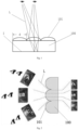
- Fig. 1 shows the principle of the lenticular grating.
- the lenticular grating 100 comprises a plurality of convexes 101 arranged in parallel.
- a width of the convex can be defined as a grating pitch d.
- light L emitted by an image I is refracted by a grating lens, and then human eyes receive different images I refracted by the grating lens from different angles, so the contents observed by the human eyes are different at different positions in front of the image I.
- Such an effect can be utilized to generate stereoscopy of pattern.
- Fig. 2 also shows the principle of the lenticular grating.
- the lenticular grating 100 includes a plurality of convexes 101 arranged in parallel, and an image behind the lenticular grating 100 includes three parts: A, B, and C.
- Light L is refracted by the lenticular grating 100, and the human eyes can simultaneously receive the three parts of the image, but the relative positions of the three parts A, B, and C are changed, thereby the lenticular grating 100 can be utilized to generate a 3D stereoscopic feeling.
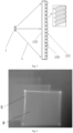
- a lenticular grating with gratings on one side will generate several light strips. If the gratings are formed on both sides of the lenticular grating, the light refracted by the first side is further scattered on the second side, which will generate complicated lighting effect.
- Fig. 3 is a schematic view of a double-sided grating according to an embodiment, which does not make part of the present invention, and Fig.
- FIG. 3 shows a lenticular grating 100 having convex structures on both sides thereof, it has a plurality of parallel vertical convexes 103 on a light entrance side of the lenticular grating 100 and a plurality of parallel horizontal convexes 102 on a light exit side of the lenticular grating 100, that is, the grating patterns on the light entrance side and the light exit side are orthogonal. Since Fig. 3 is a cross-sectional view along an extending direction of the vertical convex 103, the convex structure is not shown in the cross-sectional view.
- Fig. 4 shows a lighting effect diagram of the double-sided grating shown in Fig. 3 , and a lighting region R surrounded by a lighting boundary E in the form of a surface illumination can be seen in the figure. It should be noted that, in the embodiment shown in Fig. 3 , the patterns of the gratings on two sides are the same.
- Fig. 5 shows a light distribution element for a light emitting device according to an embodiment of the present invention.
- the light distribution element 2 includes a plurality of petal-shaped convexes 21 and a plurality of annular convexes 22.
- the petal-shaped convexes 21 protrude towards an outside of the light distribution element 2
- the annular convexes 22 protrude towards an outside of the light distribution element 2
- the pattern formed by the plurality of petal-shaped convexes 21 is significantly different from the pattern formed by the plurality of annular convexes 22.
- Fig. 5 shows a cross-sectional view along an extending direction of the petal-shaped convexes 21, the convex structures are not shown in the cross-sectional view.
- the petal-shaped convexes 21 serve as the first light deflecting portion for deflecting light beams
- the annular convexes 22 serve as the second light deflecting portion for deflecting the light beams.
- the light distribution element 2 has a light entrance side close to the light source 1 and a light exit side parallel to the light entrance side, and profiles of the light entrance side and the light exit side are circular.
- the plurality of first light deflecting portions are formed on the light entrance side of the light distribution element 2, and the plurality of second light deflecting portions are formed on the light exit side of the light distribution element 2.
- the plurality of first light deflecting portions are respectively configured for receiving different portions of an incident light beam L1 from the outside of the light distribution element 2 and deflecting them toward the second light deflecting portions, and the plurality of second light deflecting portions are respectively configured for deflecting different portions of the light beam deflected by the plurality of first light deflecting portions to form a lighting pattern P.
- the light source 1 may be any light source known from the prior art, preferably a light emitting diode.
- the light source 1 may comprise one light emitting diode or an array of light emitting diodes.
- the light source 1 may be supported by any component known in the prior art for carrying a light source, such as a lamp holder, a printed circuit board or the like.
- the plurality of petal-shaped convexes 21 extend radially outwardly from a middle of the light distribution element 2, and the plurality of annular convexes 22 have different perimeters, and the annular convex 22 having a larger perimeter is provided outside the annular convex 22 having a smaller perimeter. That is, the plurality of petal-shaped convexes 21 are radially arranged, and the plurality of annular convexes 22 are annularly arranged.
- the light distribution element for the light emitting device includes a plurality of first light deflecting portions and a plurality of second light deflecting portions, and a pattern formed by the plurality of first light deflecting portions and a pattern formed by the plurality of second light deflecting portions are different from each other.
- the first light deflecting portions and the second light deflecting portions may be constituted by lenticular gratings, which is capable of generating a personalized lighting pattern.
- the plurality of petal-shaped convexes 21 are arranged in an annular region, the plurality of petal-shaped convexes 21 extend from an inner ring of the annular region to an outer ring of the annular region, respectively, and projections of the plurality of petal-shaped convexes 21 on a plane where the light entrance side or the light exit side is located are distributed uniformly at equiangular intervals, but the projection of the petal-shaped convex 21 on the plane where the light entrance side or the light exit side is located is asymmetrical itself, that is, the plurality of petal-shaped convexes 21 twist around a center of circle of the light entrance side or the light exit side and the angle of twist at the outer ring is greater than the angle of twist at the inner ring.
- the projection of the petal-shaped convex 21 on the plane where the light entrance side or the light exit side is located may be symmetrical itself, which will result in a central rotationally symmetrical lighting pattern.
- the petal-shaped convex in the present invention has a protruding surface and the projection of the petal-shaped convex in the protruding direction has a petal-shaped profile.
- the petal-shaped profile means that the profile is surrounded by four straight lines or curves, and two opposite straight lines or curves have different side lengths.
- the petal-shaped profile of the present invention is not limited to a strict or symmetrical petal shape, but also includes an approximate petal shape and an asymmetrical petal shape, as long as it exhibits a petal shape in a general sense. Referring to Fig. 6 , the petal-shaped convex 21 presents an approximately petal-shaped profile on the paper plane while the petal-shaped convex 21 protrudes toward the outside of the paper plane.
- the lighting effect of the light distribution element for the light emitting device can be described with reference to Fig. 8 .
- a radial or petal-shaped lighting pattern is generated, and each of the petals of the lighting pattern P is slightly twisted with respect to the center of circle, therefore the lighting pattern P appears to have a rotating effect.
- the lighting effect of such a lighting pattern is very beautiful and special, and is very suitable for tail lights, brake lights, turn lights, fog lights or reverse lights of motor vehicles.
- Fig. 9 is a comparison diagram of lighting effects of a light distribution element for a light emitting device according to an embodiment of the present invention as viewed from different angles, in which lighting patterns viewed from nine directions are shown, where -20H10V refers to viewing at -20 degrees with respect to a vertical plane passing through the center of the light distribution element and at 10 degrees with respect to a horizontal plane passing through the center of the light distribution element, and so on.
- -20H10V refers to viewing at -20 degrees with respect to a vertical plane passing through the center of the light distribution element and at 10 degrees with respect to a horizontal plane passing through the center of the light distribution element, and so on.
- the lighting patterns P viewed from different angles are different, and therefore, the patterns appear to have a three-dimensional stereoscopic effect.
- a height of the petal-shaped convex 21 at the inner ring in a direction in which the petal-shaped convex 21 protrudes towards the outside of the light distribution element 2 is greater than or less than a height of the petal-shaped convex 21 at the outer ring in the direction in which the petal-shaped convex 21 protrudes towards the outside of the light distribution element 2.
- the height of the petal-shaped convex 21 between the inner ring and the outer ring in the direction in which the petal-shaped convex 21 protrudes towards the outside of the light distribution element 2 gradually changes.
- the height of the petal-shaped convex 21 between the inner ring and the outer ring in the direction in which the petal-shaped convex 21 protrudes towards the outside of the light distribution element 2 has step changes.
- a height of the annular convex 22 having a larger perimeter in a direction in which the petal-shaped convex 21 protrudes towards the outside of the light distribution element 2 is greater than or less than a height of the annular convex 22 having a smaller perimeter in the direction in which the annular convex 22 protrudes towards the outside of the light distribution element 2.
- the heights of the plurality of annular convexes 22 in the direction in which the annular convexes 22 protrude towards the outside of the light distribution element 2 gradually change in a radially outward direction from a circle center of the light entrance side or the light exit side.
- the heights of the plurality of annular convexes 22 can have step changes in the radially outward direction from the circle center of the light entrance side or the light exit side.
- the different heights of the plurality of petal-shaped convexes 21 and/or the different heights of the plurality of annular convexes 22 will generate a lighting pattern with more significant stereoscopic effect.
- the light distribution element 2 may be made of transparent glass, resin or plastic material, such as PMMA (polymethyl methacrylate), and the plurality of first light deflecting portions and the plurality of second light deflecting portions may be integrally formed with a main body of the light distribution element 2.
- the plurality of first light deflecting portions and the plurality of second light deflecting portions may be respectively constructed to be a lenticular grating film, such that the plurality of first light deflecting portions and the plurality of second light deflecting portion are constructed to be members independent of the main body of the light distribution element 2.
- the plurality of first light deflecting portions and the plurality of second light deflecting portions may be configured to be movable with respect to each other, for example, the first light deflecting portions may be moved with respect to the second light deflecting portions by the driving of a motor.
- the plurality of first light deflecting portions and the plurality of second light deflecting portions are configured to be translatable with respect to each other, so that a distance between the plurality of first light deflecting portions and the plurality of second light deflecting portions is changeable.
- the plurality of first light deflecting portions and the plurality of second light deflecting portions are configured to be rotatable with respect to each other.
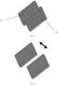
- Figs. 10-13 exemplarily show relative translation and rotation between the first light deflecting portion and the second light deflecting portion by taking lenticular gratings as an example.
- the first light deflecting portion 11 and the second light deflecting portion 12 are relatively independent of each other.
- the first light deflecting portion 11 and the second light deflecting portion 12 can be translated with respect to each other in a direction away from each other, as shown in Fig. 11 .
- first light deflecting portion 11 and the second light deflecting portion 12 can be translated in parallel with respect to each other, as shown in Fig. 12 .
- the second light deflecting portion 12 is configured to be rotatable with respect to the first light deflecting portion 11.
- the light emitting device can generate a dynamic lighting effect.
- a light emitting device comprising the light distribution element 2 for the light emitting device according to any one of the preceding embodiments.
- a personalized lighting pattern, a stereoscopic lighting effect or a dynamic lighting effect can be simply realized by using differently constructed light deflecting portions, and the technical means is simple and cost-effective.
Landscapes
- Physics & Mathematics (AREA)
- Engineering & Computer Science (AREA)
- General Engineering & Computer Science (AREA)
- General Physics & Mathematics (AREA)
- Optics & Photonics (AREA)
- Led Device Packages (AREA)
- Non-Portable Lighting Devices Or Systems Thereof (AREA)
- Planar Illumination Modules (AREA)
Claims (15)
- Lichtverteilungselement (2) für eine Licht emittierende Vorrichtung, umfassend eine Mehrzahl von ersten Lichtablenkungsabschnitten und eine Mehrzahl von zweiten Lichtablenkungsabschnitten, wobei ein durch die Mehrzahl von ersten Lichtablenkungsabschnitten gebildetes Muster mit einem durch die Mehrzahl von zweiten Lichtablenkungsabschnitten gebildeten Muster überlagert ist, um ein endgültiges Anzeigemuster zu bilden,und wobei die ersten Lichtablenkungsabschnitte so konstruiert sind, dass sie eine Mehrzahl von blütenblattförmigen konvexen Abschnitten (21) sind, die hin zu einer Außenseite des Lichtverteilungselements (2) hervorstehen, und sich die Mehrzahl von blütenblattförmigen konvexen Abschnitten (21) von einer Mitte des Lichtverteilungselements (2) radial nach außen erstreckt, undwobei die zweiten Lichtablenkungsabschnitte so konstruiert sind, dass sie eine Mehrzahl von ringförmigen konvexen Abschnitten (22) sind, die hin zu der Außenseite des Lichtverteilungselements (2) hervorstehen, wobei die Mehrzahl von ringförmigen konvexen Abschnitten (22) unterschiedliche Umfänge aufweisen und der ringförmige konvexe Abschnitt (22), der einen größeren Umfang aufweist, außerhalb des ringförmigen konvexen Abschnitts (22), der einen kleineren Umfang aufweist, bereitgestellt ist,und wobei das Lichtverteilungselement (2) eine Lichteintrittsseite und eine Lichtaustrittsseite parallel zu der Lichteintrittsseite aufweist, und wobei die Mehrzahl von ersten Lichtablenkungsabschnitten auf der Lichteintrittsseite des Lichtverteilungselements (2) gebildet sind und die Mehrzahl von zweiten Lichtablenkungsabschnitten auf der Lichtaustrittsseite des Lichtverteilungselements (2) gebildet sind.
- Lichtverteilungselement (2) nach Anspruch 1, wobei die Mehrzahl von ersten Lichtablenkungsabschnitten in einem ringförmigen Bereich angeordnet sind und sich die Mehrzahl von blütenblattförmigen konvexen Abschnitten (21) jeweils von einem Innenring des ringförmigen Bereichs zu einem Außenring des ringförmigen Bereichs erstrecken.
- Lichtverteilungselement (2) nach Anspruch 1, wobei Profile der Lichteintrittsseite und der Lichtaustrittsseite kreisförmig sind und Projektionen der Mehrzahl von blütenblattförmigen konvexen Abschnitten (21) auf eine Ebene, in der sich die Lichteintrittsseite oder die Lichtaustrittsseite befindet, einheitlich in gleichwinkligen Abständen verteilt sind.
- Lichtverteilungselement (2) nach Anspruch 3, wobei die Projektion des blütenblattförmigen konvexen Abschnitts (21) auf die Ebene, in der sich die Lichteintrittsseite oder die Lichtaustrittsseite befindet, selbst symmetrisch oder asymmetrisch ist.
- Lichtverteilungselement (2) nach Anspruch 2, wobei eine Höhe jedes blütenblattförmigen konvexen Abschnitts (21) an dem Innenring in einer Richtung, in der der jeweilige blütenblattförmige konvexe Abschnitt (21) hin zu der Außenseite des Lichtverteilungselements (2) hervorsteht, von einer Höhe jedes blütenblattförmigen konvexen Abschnitts (21) an dem Außenring in der Richtung, in der der jeweilige blütenblattförmige konvexe Abschnitt (21) hin zu der Außenseite des Lichtverteilungselements (2) hervorsteht, unterschiedlich ist.
- Lichtverteilungselement (2) nach Anspruch 5, wobei sich die Höhe jedes blütenblattförmigen konvexen Abschnitts (21) zwischen dem Innenring und dem Außenring in der Richtung, in der der jeweilige blütenblattförmige konvexe Abschnitt (21) hin zu der Außenseite des Lichtverteilungselements (2) hervorsteht, allmählich ändert.
- Lichtverteilungselement (2) nach Anspruch 1, wobei eine Höhe jedes ringförmigen konvexen Abschnitts (22) mit einem größeren Umfang in einer Richtung, in der der jeweilige blütenblattförmige konvexe Abschnitt (21) hin zu der Außenseite des Lichtverteilungselements (2) hervorsteht, von einer Höhe jedes ringförmigen konvexen Abschnitts (22) mit einem kleineren Umfang in der Richtung, in der der jeweilige ringförmige konvexe Abschnitt (22) hin zu der Außenseite des Lichtverteilungselements (2) hervorsteht, unterschiedlich ist.
- Lichtverteilungselement (2) nach Anspruch 7, wobei Profile der Lichteintrittsseite und der Lichtaustrittsseite kreisförmig sind und sich die Höhen der Mehrzahl von ringförmigen konvexen Abschnitten (22) in der Richtung, in der die ringförmigen konvexen Abschnitte (22) hin zu der Außenseite des Lichtverteilungselements (2) hervorstehen, in einer Richtung von einer Kreismitte der Lichteintrittsseite oder der Lichtaustrittsseite radial nach außen allmählich ändern.
- Lichtverteilungselement (2) nach einem der Ansprüche 1 bis 8, wobei die Mehrzahl von ersten Lichtablenkungsabschnitten und die Mehrzahl von zweiten Lichtablenkungsabschnitten integral mit einem Hauptkörper des Lichtverteilungselements (2) gebildet sind und die Mehrzahl von ersten Lichtablenkungsabschnitten und die Mehrzahl von zweiten Lichtablenkungsabschnitten jeweils auf einer Seite des Hauptkörpers des Lichtverteilungselements (2), die einer Lichtquelle zugewandt ist, und einer anderen Seite des Hauptkörpers des Lichtverteilungselements (2), die von der Lichtquelle abgewandt ist, angeordnet sind.
- Lichtverteilungselement (2) nach einem der Ansprüche 1 bis 8, wobei die Mehrzahl von ersten Lichtablenkungsabschnitten und die Mehrzahl von zweiten Lichtablenkungsabschnitten so konstruiert sind, dass sie Elemente sind, die von dem Hauptkörper des Lichtverteilungselements (2) unabhängig sind.
- Lichtverteilungselement (2) nach Anspruch 10, wobei die Mehrzahl von ersten Lichtablenkungsabschnitten und die Mehrzahl von zweiten Lichtablenkungsabschnitten jeweils so konstruiert sind, dass sie ein linsenförmiger Gitterfilm sind.
- Lichtverteilungselement (2) nach Anspruch 10 oder 11, wobei die Mehrzahl von ersten Lichtablenkungsabschnitten und die Mehrzahl von zweiten Lichtablenkungsabschnitten so ausgestaltet sind, dass sie in Bezug zueinander beweglich sind.
- Lichtverteilungselement (2) nach Anspruch 12, wobei die Mehrzahl von ersten Lichtablenkungsabschnitten und die Mehrzahl von zweiten Lichtablenkungsabschnitten so ausgestaltet sind, dass sie in Bezug zueinander translatierbar sind, so dass eine Distanz zwischen der Mehrzahl von ersten Lichtablenkungsabschnitten und der Mehrzahl von zweiten Lichtablenkungsabschnitten änderbar ist.
- Lichtverteilungselement (2) nach Anspruch 12, wobei die Mehrzahl von ersten Lichtablenkungsabschnitten und die Mehrzahl von zweiten Lichtablenkungsabschnitten so ausgestaltet sind, dass sie in Bezug zueinander drehbar sind.
- Licht emittierende Vorrichtung, die das Lichtverteilungselement (2) nach einem der Ansprüche 1 bis 14 umfasst.
Applications Claiming Priority (1)
| Application Number | Priority Date | Filing Date | Title |
|---|---|---|---|
| CN201710811209.XA CN109469884A (zh) | 2017-09-08 | 2017-09-08 | 用于发光装置的配光元件以及发光装置 |
Publications (2)
| Publication Number | Publication Date |
|---|---|
| EP3453952A1 EP3453952A1 (de) | 2019-03-13 |
| EP3453952B1 true EP3453952B1 (de) | 2023-07-05 |
Family
ID=63491425
Family Applications (1)
| Application Number | Title | Priority Date | Filing Date |
|---|---|---|---|
| EP18192085.1A Active EP3453952B1 (de) | 2017-09-08 | 2018-08-31 | Lichtverteilungselement für eine lichtemittierende vorrichtung und lichtemittierende vorrichtung |
Country Status (4)
| Country | Link |
|---|---|
| US (1) | US10605435B2 (de) |
| EP (1) | EP3453952B1 (de) |
| JP (1) | JP7274838B2 (de) |
| CN (1) | CN109469884A (de) |
Families Citing this family (10)
| Publication number | Priority date | Publication date | Assignee | Title |
|---|---|---|---|---|
| ES2781873T3 (es) | 2012-08-28 | 2020-09-08 | Delos Living Llc | Sistemas y métodos para mejorar el bienestar asociado con ambientes habitables |
| EP3111411A4 (de) | 2014-02-28 | 2017-08-09 | Delos Living, LLC | Systeme, verfahren und artikel zur verbesserung des wohlbefindens in bewohnbaren umgebungen |
| WO2019046580A1 (en) | 2017-08-30 | 2019-03-07 | Delos Living Llc | SYSTEMS, METHODS AND ARTICLES FOR EVALUATING AND / OR IMPROVING HEALTH AND WELL-BEING |
| EP3850458A4 (de) | 2018-09-14 | 2022-06-08 | Delos Living, LLC | Systeme und verfahren zur luftsanierung |
| US11844163B2 (en) | 2019-02-26 | 2023-12-12 | Delos Living Llc | Method and apparatus for lighting in an office environment |
| WO2020198183A1 (en) | 2019-03-25 | 2020-10-01 | Delos Living Llc | Systems and methods for acoustic monitoring |
| CN111649300B (zh) * | 2019-10-21 | 2023-01-10 | 摩登汽车有限公司 | 用于汽车信号灯的光学系统和包含其的汽车 |
| CN110715268B (zh) * | 2019-11-07 | 2024-08-30 | 欧普道路照明有限公司 | 配光元件和灯具 |
| DE102020110900A1 (de) | 2020-05-04 | 2021-11-04 | HELLA GmbH & Co. KGaA | Beleuchtungsvorrichtung für Fahrzeuge |
| CN115856912B (zh) * | 2023-02-06 | 2023-05-30 | 宜科(天津)电子有限公司 | 一种检测物体运动方向的数据处理系统 |
Citations (1)
| Publication number | Priority date | Publication date | Assignee | Title |
|---|---|---|---|---|
| CN203442679U (zh) * | 2012-10-30 | 2014-02-19 | 郑怡 | 一种led配光透镜 |
Family Cites Families (22)
| Publication number | Priority date | Publication date | Assignee | Title |
|---|---|---|---|---|
| KR20050042011A (ko) * | 2001-10-31 | 2005-05-04 | 쓰리엠 이노베이티브 프로퍼티즈 컴파니 | 자동차용 램프 |
| JP4282263B2 (ja) | 2001-12-28 | 2009-06-17 | 株式会社リコー | 光路切替装置および画像表示装置 |
| JP2005160750A (ja) | 2003-12-03 | 2005-06-23 | Toyo Kasei Kk | 遊技機 |
| JP2006091821A (ja) | 2004-08-26 | 2006-04-06 | Fuji Photo Film Co Ltd | プリズムシート及びこれを用いた表示装置 |
| WO2007072639A1 (ja) * | 2005-12-21 | 2007-06-28 | Nikon Corporation | オプティカルインテグレータ、照明光学装置、露光装置、およびデバイスの製造方法 |
| TW200944696A (en) * | 2008-04-18 | 2009-11-01 | Taiwan Network Comp & Electronic Co Ltd | Light distributing plate having multiple-focus grating |
| JP5394086B2 (ja) * | 2009-01-30 | 2014-01-22 | 株式会社小糸製作所 | 車両用灯具 |
| RU2013142962A (ru) | 2011-02-22 | 2015-03-27 | Конинклейке Филипс Электроникс Н.В. | Коллиматор, содержащий стопку призматических слоев, и осветительный элемент, содержащий такой коллиматор |
| JP5731932B2 (ja) * | 2011-08-25 | 2015-06-10 | 株式会社小糸製作所 | 車両用照明灯具 |
| WO2013121914A1 (ja) * | 2012-02-14 | 2013-08-22 | 凸版印刷株式会社 | 照明装置および表示装置 |
| JP2013181926A (ja) * | 2012-03-02 | 2013-09-12 | Sony Corp | 分光光学系及び分光測定装置 |
| WO2014070641A1 (en) * | 2012-10-31 | 2014-05-08 | Meacham G B Kirby | Autostereoscopic three dimensional display |
| AT514967B1 (de) | 2013-10-25 | 2015-08-15 | Zizala Lichtsysteme Gmbh | Mikroprojektions-Lichtmodul für einen Kraftfahrzeugscheinwerfer |
| WO2016050710A1 (en) * | 2014-09-29 | 2016-04-07 | Philips Lighting Holding B.V. | An optical arrangement, optical system and a method of shaping an optical beam |
| DE102014116180A1 (de) * | 2014-11-06 | 2016-05-12 | Lisa Dräxlmaier GmbH | Beleuchtungseinrichtung |
| US10317579B2 (en) | 2015-01-19 | 2019-06-11 | Signify Holding B.V. | Optical device with a collimator and lenslet arrays |
| TW201638520A (zh) * | 2015-04-30 | 2016-11-01 | 億城精密光電股份有限公司 | 可隨視角變化光型的燈具 |
| EP3364098B1 (de) * | 2015-10-16 | 2020-05-06 | FUJIFILM Corporation | Beleuchtungsvorrichtung |
| KR102415516B1 (ko) | 2015-11-20 | 2022-07-01 | 에스엘 주식회사 | 차량용 램프 |
| JPWO2017104195A1 (ja) | 2015-12-18 | 2018-06-07 | 株式会社東芝 | 光学素子およびled照明装置 |
| CN206449543U (zh) * | 2016-09-28 | 2017-08-29 | 法雷奥照明湖北技术中心有限公司 | 光图案化装置与车灯 |
| CN206330082U (zh) * | 2016-09-28 | 2017-07-14 | 法雷奥照明湖北技术中心有限公司 | 光图案化装置与车灯 |
-
2017
- 2017-09-08 CN CN201710811209.XA patent/CN109469884A/zh active Pending
-
2018
- 2018-08-31 EP EP18192085.1A patent/EP3453952B1/de active Active
- 2018-09-07 US US16/125,442 patent/US10605435B2/en active Active
- 2018-09-07 JP JP2018168020A patent/JP7274838B2/ja active Active
Patent Citations (1)
| Publication number | Priority date | Publication date | Assignee | Title |
|---|---|---|---|---|
| CN203442679U (zh) * | 2012-10-30 | 2014-02-19 | 郑怡 | 一种led配光透镜 |
Also Published As
| Publication number | Publication date |
|---|---|
| US20190107267A1 (en) | 2019-04-11 |
| US10605435B2 (en) | 2020-03-31 |
| CN109469884A (zh) | 2019-03-15 |
| EP3453952A1 (de) | 2019-03-13 |
| JP2019053295A (ja) | 2019-04-04 |
| JP7274838B2 (ja) | 2023-05-17 |
Similar Documents
| Publication | Publication Date | Title |
|---|---|---|
| US10605435B2 (en) | Light distribution element for light emitting device and light emitting device | |
| KR100438932B1 (ko) | 차량용 표지등 | |
| JP5369359B2 (ja) | 灯具 | |
| JP6383953B2 (ja) | 照明装置およびその照明装置を搭載した自動車 | |
| CN106838760A (zh) | 用于将光以预定的照明图样投射在表面上的照明装置 | |
| JP7506809B2 (ja) | 車両用灯具 | |
| KR20170059325A (ko) | 차량용 램프 | |
| US20140362588A1 (en) | Light guide lens | |
| JP2009164126A (ja) | 車両用照明装置 | |
| CN103939819B (zh) | 用于车辆的照明装置 | |
| JP2017224475A (ja) | 車両用灯具 | |
| US20180216795A1 (en) | Motor vehicle lamp and motor vehicle | |
| US20140198517A1 (en) | Vehicular headlamp | |
| KR20150017220A (ko) | 광원 모듈 및 이를 포함하는 차량용 램프 | |
| CN110469817A (zh) | 用于车灯的光学组件、车灯和机动车辆 | |
| CN113531480A (zh) | 车辆用灯具 | |
| JP5302146B2 (ja) | 道路用発光標示体 | |
| CN222732677U (zh) | 反射镜、照明模组、车灯及车辆 | |
| JP6676367B2 (ja) | 発光具 | |
| CN109990240B (zh) | 光学组件、车灯和机动车辆 | |
| JP2006216455A (ja) | 車両用標識灯 | |
| KR102383731B1 (ko) | 발광형 표지판 | |
| JP6994576B2 (ja) | 車両ライト及びその光路伝導装置 | |
| JP2003323805A (ja) | 車両用信号灯具 | |
| JP5170562B2 (ja) | レンズ、及び、灯具 |
Legal Events
| Date | Code | Title | Description |
|---|---|---|---|
| PUAI | Public reference made under article 153(3) epc to a published international application that has entered the european phase |
Free format text: ORIGINAL CODE: 0009012 |
|
| STAA | Information on the status of an ep patent application or granted ep patent |
Free format text: STATUS: REQUEST FOR EXAMINATION WAS MADE |
|
| 17P | Request for examination filed |
Effective date: 20180831 |
|
| AK | Designated contracting states |
Kind code of ref document: A1 Designated state(s): AL AT BE BG CH CY CZ DE DK EE ES FI FR GB GR HR HU IE IS IT LI LT LU LV MC MK MT NL NO PL PT RO RS SE SI SK SM TR |
|
| AX | Request for extension of the european patent |
Extension state: BA ME |
|
| STAA | Information on the status of an ep patent application or granted ep patent |
Free format text: STATUS: EXAMINATION IS IN PROGRESS |
|
| 17Q | First examination report despatched |
Effective date: 20220119 |
|
| RIC1 | Information provided on ipc code assigned before grant |
Ipc: G02B 26/08 20060101ALN20221221BHEP Ipc: G02B 3/00 20060101ALI20221221BHEP Ipc: F21S 43/20 20180101AFI20221221BHEP |
|
| GRAP | Despatch of communication of intention to grant a patent |
Free format text: ORIGINAL CODE: EPIDOSNIGR1 |
|
| STAA | Information on the status of an ep patent application or granted ep patent |
Free format text: STATUS: GRANT OF PATENT IS INTENDED |
|
| INTG | Intention to grant announced |
Effective date: 20230202 |
|
| GRAS | Grant fee paid |
Free format text: ORIGINAL CODE: EPIDOSNIGR3 |
|
| GRAA | (expected) grant |
Free format text: ORIGINAL CODE: 0009210 |
|
| STAA | Information on the status of an ep patent application or granted ep patent |
Free format text: STATUS: THE PATENT HAS BEEN GRANTED |
|
| AK | Designated contracting states |
Kind code of ref document: B1 Designated state(s): AL AT BE BG CH CY CZ DE DK EE ES FI FR GB GR HR HU IE IS IT LI LT LU LV MC MK MT NL NO PL PT RO RS SE SI SK SM TR |
|
| P01 | Opt-out of the competence of the unified patent court (upc) registered |
Effective date: 20230528 |
|
| REG | Reference to a national code |
Ref country code: CH Ref legal event code: EP |
|
| REG | Reference to a national code |
Ref country code: AT Ref legal event code: REF Ref document number: 1585149 Country of ref document: AT Kind code of ref document: T Effective date: 20230715 |
|
| REG | Reference to a national code |
Ref country code: DE Ref legal event code: R096 Ref document number: 602018052730 Country of ref document: DE |
|
| REG | Reference to a national code |
Ref country code: IE Ref legal event code: FG4D |
|
| REG | Reference to a national code |
Ref country code: LT Ref legal event code: MG9D |
|
| REG | Reference to a national code |
Ref country code: NL Ref legal event code: MP Effective date: 20230705 |
|
| REG | Reference to a national code |
Ref country code: AT Ref legal event code: MK05 Ref document number: 1585149 Country of ref document: AT Kind code of ref document: T Effective date: 20230705 |
|
| PG25 | Lapsed in a contracting state [announced via postgrant information from national office to epo] |
Ref country code: NL Free format text: LAPSE BECAUSE OF FAILURE TO SUBMIT A TRANSLATION OF THE DESCRIPTION OR TO PAY THE FEE WITHIN THE PRESCRIBED TIME-LIMIT Effective date: 20230705 |
|
| PG25 | Lapsed in a contracting state [announced via postgrant information from national office to epo] |
Ref country code: GR Free format text: LAPSE BECAUSE OF FAILURE TO SUBMIT A TRANSLATION OF THE DESCRIPTION OR TO PAY THE FEE WITHIN THE PRESCRIBED TIME-LIMIT Effective date: 20231006 |
|
| PG25 | Lapsed in a contracting state [announced via postgrant information from national office to epo] |
Ref country code: ES Free format text: LAPSE BECAUSE OF FAILURE TO SUBMIT A TRANSLATION OF THE DESCRIPTION OR TO PAY THE FEE WITHIN THE PRESCRIBED TIME-LIMIT Effective date: 20230705 |
|
| PG25 | Lapsed in a contracting state [announced via postgrant information from national office to epo] |
Ref country code: IS Free format text: LAPSE BECAUSE OF FAILURE TO SUBMIT A TRANSLATION OF THE DESCRIPTION OR TO PAY THE FEE WITHIN THE PRESCRIBED TIME-LIMIT Effective date: 20231105 |
|
| PG25 | Lapsed in a contracting state [announced via postgrant information from national office to epo] |
Ref country code: SE Free format text: LAPSE BECAUSE OF FAILURE TO SUBMIT A TRANSLATION OF THE DESCRIPTION OR TO PAY THE FEE WITHIN THE PRESCRIBED TIME-LIMIT Effective date: 20230705 Ref country code: RS Free format text: LAPSE BECAUSE OF FAILURE TO SUBMIT A TRANSLATION OF THE DESCRIPTION OR TO PAY THE FEE WITHIN THE PRESCRIBED TIME-LIMIT Effective date: 20230705 Ref country code: PT Free format text: LAPSE BECAUSE OF FAILURE TO SUBMIT A TRANSLATION OF THE DESCRIPTION OR TO PAY THE FEE WITHIN THE PRESCRIBED TIME-LIMIT Effective date: 20231106 Ref country code: NO Free format text: LAPSE BECAUSE OF FAILURE TO SUBMIT A TRANSLATION OF THE DESCRIPTION OR TO PAY THE FEE WITHIN THE PRESCRIBED TIME-LIMIT Effective date: 20231005 Ref country code: LV Free format text: LAPSE BECAUSE OF FAILURE TO SUBMIT A TRANSLATION OF THE DESCRIPTION OR TO PAY THE FEE WITHIN THE PRESCRIBED TIME-LIMIT Effective date: 20230705 Ref country code: LT Free format text: LAPSE BECAUSE OF FAILURE TO SUBMIT A TRANSLATION OF THE DESCRIPTION OR TO PAY THE FEE WITHIN THE PRESCRIBED TIME-LIMIT Effective date: 20230705 Ref country code: IS Free format text: LAPSE BECAUSE OF FAILURE TO SUBMIT A TRANSLATION OF THE DESCRIPTION OR TO PAY THE FEE WITHIN THE PRESCRIBED TIME-LIMIT Effective date: 20231105 Ref country code: HR Free format text: LAPSE BECAUSE OF FAILURE TO SUBMIT A TRANSLATION OF THE DESCRIPTION OR TO PAY THE FEE WITHIN THE PRESCRIBED TIME-LIMIT Effective date: 20230705 Ref country code: GR Free format text: LAPSE BECAUSE OF FAILURE TO SUBMIT A TRANSLATION OF THE DESCRIPTION OR TO PAY THE FEE WITHIN THE PRESCRIBED TIME-LIMIT Effective date: 20231006 Ref country code: FI Free format text: LAPSE BECAUSE OF FAILURE TO SUBMIT A TRANSLATION OF THE DESCRIPTION OR TO PAY THE FEE WITHIN THE PRESCRIBED TIME-LIMIT Effective date: 20230705 Ref country code: ES Free format text: LAPSE BECAUSE OF FAILURE TO SUBMIT A TRANSLATION OF THE DESCRIPTION OR TO PAY THE FEE WITHIN THE PRESCRIBED TIME-LIMIT Effective date: 20230705 Ref country code: AT Free format text: LAPSE BECAUSE OF FAILURE TO SUBMIT A TRANSLATION OF THE DESCRIPTION OR TO PAY THE FEE WITHIN THE PRESCRIBED TIME-LIMIT Effective date: 20230705 |
|
| PG25 | Lapsed in a contracting state [announced via postgrant information from national office to epo] |
Ref country code: PL Free format text: LAPSE BECAUSE OF FAILURE TO SUBMIT A TRANSLATION OF THE DESCRIPTION OR TO PAY THE FEE WITHIN THE PRESCRIBED TIME-LIMIT Effective date: 20230705 |
|
| REG | Reference to a national code |
Ref country code: CH Ref legal event code: PL |
|
| REG | Reference to a national code |
Ref country code: DE Ref legal event code: R097 Ref document number: 602018052730 Country of ref document: DE |
|
| PG25 | Lapsed in a contracting state [announced via postgrant information from national office to epo] |
Ref country code: LU Free format text: LAPSE BECAUSE OF NON-PAYMENT OF DUE FEES Effective date: 20230831 |
|
| PG25 | Lapsed in a contracting state [announced via postgrant information from national office to epo] |
Ref country code: SM Free format text: LAPSE BECAUSE OF FAILURE TO SUBMIT A TRANSLATION OF THE DESCRIPTION OR TO PAY THE FEE WITHIN THE PRESCRIBED TIME-LIMIT Effective date: 20230705 Ref country code: RO Free format text: LAPSE BECAUSE OF FAILURE TO SUBMIT A TRANSLATION OF THE DESCRIPTION OR TO PAY THE FEE WITHIN THE PRESCRIBED TIME-LIMIT Effective date: 20230705 Ref country code: LU Free format text: LAPSE BECAUSE OF NON-PAYMENT OF DUE FEES Effective date: 20230831 Ref country code: EE Free format text: LAPSE BECAUSE OF FAILURE TO SUBMIT A TRANSLATION OF THE DESCRIPTION OR TO PAY THE FEE WITHIN THE PRESCRIBED TIME-LIMIT Effective date: 20230705 Ref country code: DK Free format text: LAPSE BECAUSE OF FAILURE TO SUBMIT A TRANSLATION OF THE DESCRIPTION OR TO PAY THE FEE WITHIN THE PRESCRIBED TIME-LIMIT Effective date: 20230705 Ref country code: CZ Free format text: LAPSE BECAUSE OF FAILURE TO SUBMIT A TRANSLATION OF THE DESCRIPTION OR TO PAY THE FEE WITHIN THE PRESCRIBED TIME-LIMIT Effective date: 20230705 Ref country code: MC Free format text: LAPSE BECAUSE OF FAILURE TO SUBMIT A TRANSLATION OF THE DESCRIPTION OR TO PAY THE FEE WITHIN THE PRESCRIBED TIME-LIMIT Effective date: 20230705 Ref country code: SK Free format text: LAPSE BECAUSE OF FAILURE TO SUBMIT A TRANSLATION OF THE DESCRIPTION OR TO PAY THE FEE WITHIN THE PRESCRIBED TIME-LIMIT Effective date: 20230705 Ref country code: CH Free format text: LAPSE BECAUSE OF NON-PAYMENT OF DUE FEES Effective date: 20230831 |
|
| REG | Reference to a national code |
Ref country code: BE Ref legal event code: MM Effective date: 20230831 |
|
| PLBE | No opposition filed within time limit |
Free format text: ORIGINAL CODE: 0009261 |
|
| STAA | Information on the status of an ep patent application or granted ep patent |
Free format text: STATUS: NO OPPOSITION FILED WITHIN TIME LIMIT |
|
| REG | Reference to a national code |
Ref country code: IE Ref legal event code: MM4A |
|
| PG25 | Lapsed in a contracting state [announced via postgrant information from national office to epo] |
Ref country code: IT Free format text: LAPSE BECAUSE OF FAILURE TO SUBMIT A TRANSLATION OF THE DESCRIPTION OR TO PAY THE FEE WITHIN THE PRESCRIBED TIME-LIMIT Effective date: 20230705 |
|
| 26N | No opposition filed |
Effective date: 20240408 |
|
| GBPC | Gb: european patent ceased through non-payment of renewal fee |
Effective date: 20231005 |
|
| PG25 | Lapsed in a contracting state [announced via postgrant information from national office to epo] |
Ref country code: IE Free format text: LAPSE BECAUSE OF NON-PAYMENT OF DUE FEES Effective date: 20230831 |
|
| PG25 | Lapsed in a contracting state [announced via postgrant information from national office to epo] |
Ref country code: GB Free format text: LAPSE BECAUSE OF NON-PAYMENT OF DUE FEES Effective date: 20231005 |
|
| PG25 | Lapsed in a contracting state [announced via postgrant information from national office to epo] |
Ref country code: IE Free format text: LAPSE BECAUSE OF NON-PAYMENT OF DUE FEES Effective date: 20230831 Ref country code: GB Free format text: LAPSE BECAUSE OF NON-PAYMENT OF DUE FEES Effective date: 20231005 Ref country code: SI Free format text: LAPSE BECAUSE OF FAILURE TO SUBMIT A TRANSLATION OF THE DESCRIPTION OR TO PAY THE FEE WITHIN THE PRESCRIBED TIME-LIMIT Effective date: 20230705 |
|
| PG25 | Lapsed in a contracting state [announced via postgrant information from national office to epo] |
Ref country code: BE Free format text: LAPSE BECAUSE OF NON-PAYMENT OF DUE FEES Effective date: 20230831 |
|
| PG25 | Lapsed in a contracting state [announced via postgrant information from national office to epo] |
Ref country code: BG Free format text: LAPSE BECAUSE OF FAILURE TO SUBMIT A TRANSLATION OF THE DESCRIPTION OR TO PAY THE FEE WITHIN THE PRESCRIBED TIME-LIMIT Effective date: 20230705 |
|
| PG25 | Lapsed in a contracting state [announced via postgrant information from national office to epo] |
Ref country code: BG Free format text: LAPSE BECAUSE OF FAILURE TO SUBMIT A TRANSLATION OF THE DESCRIPTION OR TO PAY THE FEE WITHIN THE PRESCRIBED TIME-LIMIT Effective date: 20230705 |
|
| PG25 | Lapsed in a contracting state [announced via postgrant information from national office to epo] |
Ref country code: CY Free format text: LAPSE BECAUSE OF FAILURE TO SUBMIT A TRANSLATION OF THE DESCRIPTION OR TO PAY THE FEE WITHIN THE PRESCRIBED TIME-LIMIT; INVALID AB INITIO Effective date: 20180831 |
|
| PG25 | Lapsed in a contracting state [announced via postgrant information from national office to epo] |
Ref country code: HU Free format text: LAPSE BECAUSE OF FAILURE TO SUBMIT A TRANSLATION OF THE DESCRIPTION OR TO PAY THE FEE WITHIN THE PRESCRIBED TIME-LIMIT; INVALID AB INITIO Effective date: 20180831 |
|
| PGFP | Annual fee paid to national office [announced via postgrant information from national office to epo] |
Ref country code: DE Payment date: 20250812 Year of fee payment: 8 |
|
| PGFP | Annual fee paid to national office [announced via postgrant information from national office to epo] |
Ref country code: FR Payment date: 20250828 Year of fee payment: 8 |
|
| PG25 | Lapsed in a contracting state [announced via postgrant information from national office to epo] |
Ref country code: TR Free format text: LAPSE BECAUSE OF FAILURE TO SUBMIT A TRANSLATION OF THE DESCRIPTION OR TO PAY THE FEE WITHIN THE PRESCRIBED TIME-LIMIT Effective date: 20230705 |