EP3453795B1 - Washing machine - Google Patents
Washing machine Download PDFInfo
- Publication number
- EP3453795B1 EP3453795B1 EP17831207.0A EP17831207A EP3453795B1 EP 3453795 B1 EP3453795 B1 EP 3453795B1 EP 17831207 A EP17831207 A EP 17831207A EP 3453795 B1 EP3453795 B1 EP 3453795B1
- Authority
- EP
- European Patent Office
- Prior art keywords
- drum
- washing machine
- pulsator
- rotor
- tub
- Prior art date
- Legal status (The legal status is an assumption and is not a legal conclusion. Google has not performed a legal analysis and makes no representation as to the accuracy of the status listed.)
- Active
Links
- 238000005406 washing Methods 0.000 title claims description 100
- XLYOFNOQVPJJNP-UHFFFAOYSA-N water Substances O XLYOFNOQVPJJNP-UHFFFAOYSA-N 0.000 claims description 24
- 230000008878 coupling Effects 0.000 claims description 6
- 238000010168 coupling process Methods 0.000 claims description 6
- 238000005859 coupling reaction Methods 0.000 claims description 6
- 238000009751 slip forming Methods 0.000 claims 1
- 239000003599 detergent Substances 0.000 description 5
- 230000009977 dual effect Effects 0.000 description 4
- 239000011521 glass Substances 0.000 description 4
- 230000003247 decreasing effect Effects 0.000 description 2
- 230000002708 enhancing effect Effects 0.000 description 2
- 230000014509 gene expression Effects 0.000 description 2
- 230000005540 biological transmission Effects 0.000 description 1
- 230000018044 dehydration Effects 0.000 description 1
- 238000006297 dehydration reaction Methods 0.000 description 1
- 230000001419 dependent effect Effects 0.000 description 1
- 230000000694 effects Effects 0.000 description 1
- 230000004048 modification Effects 0.000 description 1
- 238000012986 modification Methods 0.000 description 1
- 238000005086 pumping Methods 0.000 description 1
- 238000007789 sealing Methods 0.000 description 1
- 239000000725 suspension Substances 0.000 description 1
- 239000005341 toughened glass Substances 0.000 description 1
Images


Classifications
-
- D—TEXTILES; PAPER
- D06—TREATMENT OF TEXTILES OR THE LIKE; LAUNDERING; FLEXIBLE MATERIALS NOT OTHERWISE PROVIDED FOR
- D06F—LAUNDERING, DRYING, IRONING, PRESSING OR FOLDING TEXTILE ARTICLES
- D06F37/00—Details specific to washing machines covered by groups D06F21/00 - D06F25/00
- D06F37/30—Driving arrangements
- D06F37/40—Driving arrangements for driving the receptacle and an agitator or impeller, e.g. alternatively
-
- D—TEXTILES; PAPER
- D06—TREATMENT OF TEXTILES OR THE LIKE; LAUNDERING; FLEXIBLE MATERIALS NOT OTHERWISE PROVIDED FOR
- D06F—LAUNDERING, DRYING, IRONING, PRESSING OR FOLDING TEXTILE ARTICLES
- D06F37/00—Details specific to washing machines covered by groups D06F21/00 - D06F25/00
- D06F37/02—Rotary receptacles, e.g. drums
- D06F37/04—Rotary receptacles, e.g. drums adapted for rotation or oscillation about a horizontal or inclined axis
- D06F37/06—Ribs, lifters, or rubbing means forming part of the receptacle
- D06F37/065—Ribs, lifters, or rubbing means forming part of the receptacle ribs or lifters having means for circulating the washing liquid
-
- D—TEXTILES; PAPER
- D06—TREATMENT OF TEXTILES OR THE LIKE; LAUNDERING; FLEXIBLE MATERIALS NOT OTHERWISE PROVIDED FOR
- D06F—LAUNDERING, DRYING, IRONING, PRESSING OR FOLDING TEXTILE ARTICLES
- D06F17/00—Washing machines having receptacles, stationary for washing purposes, wherein the washing action is effected solely by circulation or agitation of the washing liquid
- D06F17/06—Washing machines having receptacles, stationary for washing purposes, wherein the washing action is effected solely by circulation or agitation of the washing liquid by rotary impellers
- D06F17/08—Driving arrangements for the impeller
-
- D—TEXTILES; PAPER
- D06—TREATMENT OF TEXTILES OR THE LIKE; LAUNDERING; FLEXIBLE MATERIALS NOT OTHERWISE PROVIDED FOR
- D06F—LAUNDERING, DRYING, IRONING, PRESSING OR FOLDING TEXTILE ARTICLES
- D06F23/00—Washing machines with receptacles, e.g. perforated, having a rotary movement, e.g. oscillatory movement, the receptacle serving both for washing and for centrifugally separating water from the laundry
- D06F23/02—Washing machines with receptacles, e.g. perforated, having a rotary movement, e.g. oscillatory movement, the receptacle serving both for washing and for centrifugally separating water from the laundry and rotating or oscillating about a horizontal axis
-
- D—TEXTILES; PAPER
- D06—TREATMENT OF TEXTILES OR THE LIKE; LAUNDERING; FLEXIBLE MATERIALS NOT OTHERWISE PROVIDED FOR
- D06F—LAUNDERING, DRYING, IRONING, PRESSING OR FOLDING TEXTILE ARTICLES
- D06F37/00—Details specific to washing machines covered by groups D06F21/00 - D06F25/00
- D06F37/20—Mountings, e.g. resilient mountings, for the rotary receptacle, motor, tub or casing; Preventing or damping vibrations
- D06F37/22—Mountings, e.g. resilient mountings, for the rotary receptacle, motor, tub or casing; Preventing or damping vibrations in machines with a receptacle rotating or oscillating about a horizontal axis
-
- Y—GENERAL TAGGING OF NEW TECHNOLOGICAL DEVELOPMENTS; GENERAL TAGGING OF CROSS-SECTIONAL TECHNOLOGIES SPANNING OVER SEVERAL SECTIONS OF THE IPC; TECHNICAL SUBJECTS COVERED BY FORMER USPC CROSS-REFERENCE ART COLLECTIONS [XRACs] AND DIGESTS
- Y02—TECHNOLOGIES OR APPLICATIONS FOR MITIGATION OR ADAPTATION AGAINST CLIMATE CHANGE
- Y02B—CLIMATE CHANGE MITIGATION TECHNOLOGIES RELATED TO BUILDINGS, e.g. HOUSING, HOUSE APPLIANCES OR RELATED END-USER APPLICATIONS
- Y02B40/00—Technologies aiming at improving the efficiency of home appliances, e.g. induction cooking or efficient technologies for refrigerators, freezers or dish washers
Definitions
- the present disclosure relates to a washing machine, and more particularly, to a washing machine capable of independently driving a drum and a pulsator.
- a washing machine is a machine for washing clothes using electric power, and generally includes a tub for storing washing water and a drum rotatably installed inside the tub.
- the washing machine includes a drum type washing machine for washing the laundry by raising and lowering the laundry while the rotating tub is rotating, and an electric washing machine for washing the laundry using water flows generated by the pulsator when the rotating tub is rotated.
- the rotating axis of the drum is arranged in a substantially horizontal direction, so that the laundry is lifted and dropped as the drum is rotated, thereby washing the laundry.
- the conventional drum type washing machine includes a lifter provided inside the drum for lifting the laundry upward. Unlike the electric washing machine, the conventional drum type washing machine is not provided with a pulsator for generating water flows inside the drum.
- WO 2015/158044 A1 and WO 2009/062920 A1 relate to drum-type washing machines comprising a main body having a laundry inlet on a front surface portion thereof and having a drum, a pulsator and a pulley motor, whereby the pulsator is disposed inside the drum on a side of the drum facing opposite the laundry inlet and is configured to be rotated separately from the drum.
- US 2014/0190219 A1 relates to a drum-type washing machine having a main drum and a sub-drum with lifters and a driving motor.
- WO 2015/127823 A1 , FR 1 227 699 A , and JP 2010-046323 A relate to drum-type washing machines having a drum, a pulsator and a driving motor.
- WO 2015/009106 A1 relates to a motor for a washing machine.
- US 2011/088276 A1 , CN 203 420 126 U , US 2005/132556 A1 , and EP 2 455 531 A1 relate to drum-type washing machines having a drum with through holes formed as protrusions.
- One aspect of the present disclosure discloses a drum type washing machine having no lifter but a pulsator.
- Another aspect of the present disclosure discloses a drum type washing machine capable of independently driving a drum and a pulsator by adopting a dual drive motor.
- Still another aspect of the present disclosure discloses a drum type washing machine capable of improving washing performance with a pulsator driven independently of a drum.
- Yet another aspect of the present disclosure discloses a drum type washing machine capable of reducing washing time with improved washing performance by providing a pulsator driven independently of a drum.
- the drum and the pulsator may have different rotating directions.
- the driving device may include an annular stator, a first rotor rotating inside the stator, and a second rotor rotating outside the stator.
- a washing machine may independently drive a drum and a pulsator using a dual drive motor, thereby improving washing performance and reducing washing time.
- first a first component
- second a second component
- first component a first component
- first component a second component
- first component a first component
- second component a second component
- first component without departing from the scope of the claims of the disclosure.
- and/or encompasses combinations of a plurality of items or any one of the plurality of items.
- front end used in the following description are defined based on the drawing, but a shape and a location of each element are not limited by those terms.
- a front loading type washing machine for inputting laundry through the front of the washing machine will be described, but the present disclosure is not limited thereto and the present disclosure is also applicable to a top loading type washing machine in which laundry is loaded from above the washing machine, however such a top-loading machine configuration does not form part of the claimed invention.
- FIG. 1 is a lateral cross-sectional view illustrating a schematic configuration of a washing machine 1 according to an embodiment of the present invention.
- FIG. 2 is a view illustrating an inside of the washing machine 1 shown in FIG. 1 .
- the washing machine 1 includes a main body 10 forming an outer appearance and containing various components, a tub 20 provided inside the main body 10 to store washing water, a drum 110 that receives and rotates laundry, a pulsator 120 rotatably disposed inside the drum 110, and a driving device 130 rotating the drum 110 and the pulsator 120.
- the main body 10 may substantially have a box shape.
- the main body 10 may have a front plate, a rear plate, a top plate, a bottom plate, and side plates.
- the front plate is provided with a laundry inlet 10a to allow laundry to be thrown into the drum 110.
- the laundry inlet 10a of the main body 10 may be opened or closed by a door 60.
- the door 60 may be rotatably coupled to the main body 10 by a hinge member.
- the door 60 may be composed of a glass member and a door frame for supporting the glass member.
- the glass member may be formed of a transparent tempered glass to be looked through to the inside of the main body 10.
- the glass member may be provided to protrude toward the inside of the tub 20 so as to prevent the laundry from being biased toward the door 60.
- the tub 20 stores the washing water and may be formed in a substantially cylindrical shape.
- the tub 20 may be supported by a suspension.
- the tub 20 may include a hollow cylindrical portion 21, an opening 22 formed on one side of the cylindrical portion 21 to correspond to the laundry inlet 10a of the main body 10, and a bottom portion 23 formed on the other side of the cylindrical portion 21.
- the laundry inlet 10a of the front plate of the main body 10 and the opening 22 of the tub 20 may be connected by a diaphragm 50.
- the diaphragm 50 forms a passage for connecting the laundry inlet 10a of the front plate of the main body 10 and the opening 22 of the tub 20, guides the laundry thrown into the laundry inlet 10a into the drum 110, and reduces transmission of vibration generated during rotation of the drum 110 to the main body 10.
- the washing machine 1 may include a drainage device 16 capable of draining the washing water from the tub 20.
- the drainage device 16 may include a drain pipe 17 connected to the lower portion of the tub 20 to guide the washing water to the outside of the main body 10 and a drain pump for pumping the washing water of the tub 20.
- a water supply device 11 for supplying washing water to the inside of the tub 20 may be provided at an upper portion of the tub 20.
- the water supply device 11 may include a water supply pipe 12 for supplying washing water from an external water supply source and a water supply valve for opening or closing the water supply pipe 12.
- a detergent supply device 14 for supplying detergent to the tub 20 may be provided at an upper portion of the front side of the main body 10.
- the detergent supply device 14 may be connected to the tub 20 through a connecting pipe.
- the washing water supplied by the water supply pipe 12 may be supplied to the inside of the tub 20 together with the detergent by the detergent supply device 14.
- FIG. 3 is a view illustrating an inside of the tub 20, the drum 110, and the pulsator 120 of the washing machine 1 according to an embodiment of the present invention.
- FIG. 4 is an enlarged view of a portion of the washing machine 1 shown in FIG. 1 .
- FIG. 5 is an enlarged view of a portion of the washing machine 1 shown in FIG. 1 .
- Through holes 111 of the drum 110 are not shown in FIG. 4 .
- the drum 110 has a substantially cylindrical shape with its front surface opened, and is provided inside the tub 20.
- the drum 110 may be disposed such that its central axis is parallel to the center axis of the tub 20.
- the drum 110 is configured to rotate inside the tub 20.
- the drum 110 may perform washing by raising and lowering the laundry while rotating. Since the drum 110 in accordance with an embodiment of the present disclosure has no extra structure on its inner surface, it may secure a larger washing space.
- the washing machine 1 of the washing machine 1 according to the embodiment of the present invention may rotate at a speed higher than that of the conventional washing machine.
- the drum rotates at 45 revolutions per minute (rpm)
- the washing machine 1 according to the embodiment of the present disclosure may rotate the drum 110 at 70 to 80 rpm. That is, in the washing machine 1 according to the embodiment of the present disclosure, the drum 110 may be rotated to such an extent that the laundry is raised by the centrifugal force and then dropped.
- the drum 110 of the washing machine 1 has multiple through holes 111 formed continuously along the circumferential face of the drum 110.
- the multiple through holes are not formed continuously along the circumferential face of the drum because a lifter is arranged in a portion of the inner circumferential face of the drum to lift the laundry. That is, the through holes are not formed in the portion where the lifter is arranged.
- the washing machine 1 in accordance with the present invention has the multiple through holes 111 formed along the circumferential face of the drum 110, allowing more washing water to be brought into the drum 110, thereby enhancing washing performance.
- a protrusion 112 forming the through hole 111 is formed to protrude inward from the drum 110.
- the drum 110 is connected to the driving device 130, which will be described later, on the opposite side to a side facing the laundry inlet 10a.
- the pulsator 120 is provided on the opposite side to the side facing the laundry inlet 10a of the drum 110 and is configured to rotate independently of the drum 110. That is, the pulsator 120 can rotate in a direction different from the direction of rotation of the drum 110.
- the pulsator 120 includes a first blade 121a, a second blade 121b, and a coupling portion 122.
- the first blade 121a is larger than the second blade 121b.
- the second blade 121b is provided in a smaller size than the first blade 121a, a wider washing space may be secured.
- the washing machine 1 When viewed from the front where the door 60 is provided in FIG. 1 , the washing machine 1 according to the embodiment of the present invention can also agitate the laundry in the front-back directions (hereinafter, such directions are referred to as a front-and-back direction) by the first blade 121a and the second blade 121b to prevent the laundry from sticking to the drum 110 as the drum 110 rotates at high speed as described above.
- a front-and-back direction front-and-back direction
- the pulsator 120 may be connected to a second driving shaft 132, which will be described later and is configured to rotate by receiving power from the driving device 130.
- the coupling portion 122 of the pulsator 120 may be connected and fixed to the second driving shaft 132 by the coupling portion fixing member 124.
- the driving device 130 may be provided behind the tub 20 and is configured to provide power for simultaneously or selectively rotating the drum 110 and the pulsator 120.
- the driving device 130 may include a first driving shaft 131 connected to the drum 110, the second driving shaft 132 rotatably disposed in the first driving shaft 131 and connected to the pulsator 120, a first rotor 133 connected to the first driving shaft 131, a second rotor 134 connected to the second driving shaft 132, and a stator 135 disposed with a gap between the first rotor 133 and the second rotor 134.
- the driving device 130 may convert the electric force to a mechanical rotational force.
- the driving device 130 may be a dual drive motor that may rotate the drum 110 and the pulsator 120, respectively.
- the rotational force generated by the driving device 130 may be transmitted to the drum 110 through the first driving shaft 134 and may be transmitted to the pulsator 120 through the second driving shaft 135 provided inside the first driving shaft 134.
- the first driving shaft 134 may be press-fitted into the first rotor 133, may rotate together with the first rotor 133, and may pass through the rear wall of the tub 20 to connect the drum 110 and the driving device 130.
- a first bearing 136a and a second bearing 136b that rotatably support the first driving shaft 131 may be disposed on the outer circumferential surface of the first driving shaft 131 with a predetermined gap between them.
- the first bearing 136a and the second bearing 136b may be fixed to the tub 20.
- the first driving shaft 131 may have a cylindrical shape so that the second driving shaft 132 may pass through.
- the first driving shaft 131 may include a first stepped portion 131a with the decreasing outer diameter to have the first bearing 136a mounted thereon without being moved in the vertical direction, and a second stepped portion 131b with the decreasing outer diameter to have the second bearing 136b mounted thereon without being moved in the vertical direction.
- the first driving shaft 131 may have a first connecting portion 131c connected to the first rotor 133 at a lower side of a portion where the first bearing 136a is mounted, a first fixing nut 131d for fixing the first rotor 133 to the first driving shaft 131 may be fastened to the lower side of the first connecting portion 131c.
- the first driving shaft 131 may include a second connecting portion 131e formed on the upper side of a portion where the second bearing 136b is inserted, and connected to a flange member 128 that connects the first driving shaft 131 and the bottom of the drum 110 to transmit the rotational force of the first driving shaft 131 to the drum 110.
- the first connecting portion 131c and the second connecting portion 131e may form a screw thread on the outer circumferential surface of the first driving shaft 131 and may be coupled with the first rotor 133 and the flange member 128, respectively, by screwing, but embodiments of the present disclosure are not limited thereto and the first connecting portion 131c and the second connecting portion 131e may have any structure as long as the structure may connect the first rotor 133 and the flange member 128 to the outer surface of the first driving shaft 131.
- the second driving shaft 135 may be press-fitted into the second rotor 133 rotated together with the second rotor 133, and rotatably provided in the hollow interior of the first driving shaft 134.
- the second driving shaft 135 may pass through the rear wall of the tub 20 to connect the pulsator 120 and the driving device 130.
- the second driving shaft 132 may have a third connecting portion 132a connected to the second rotor 134 by being drawn out from the lower end of the first driving shaft 131 at a lower portion of the second driving shaft 132, and a second fixing nut 132b may be fastened to the bottom end of the lower portion to prevent detachment of the second rotor 134.
- the second driving shaft 132 may have a fourth connecting portion 132c connected to the pulsator 120 by being drawn from the upper end of the first driving shaft 131 at an upper portion of the second driving shaft 132.
- the third connecting portion 132a and the fourth connecting portion 132c may form a screw thread on the outer circumferential surface of the second driving shaft 132 and be screwed with the second rotor 133 and the pulsator 120, respectively, but embodiments of the present disclosure are not limited thereto and the third connecting portion 132a and the fourth connecting portion 132c may have any structure as long as the structure may connect the second rotor 134 and the pulsator 120 to the outer surface of the second driving shaft 132.
- a first sleeve bearing 137a and a second sleeve bearing 137b are fixed to the upper inner circumferential surface and the lower inner circumferential surface of the first driving shaft 131, respectively, and the second driving shaft 132 may be rotatably supported by the first sleeve bearing 137a and the second sleeve bearing 137b.
- a sealing member 138 may be provided between the upper inner surface of the first driving shaft 131 and the upper outer surface of the second driving shaft 132 to prevent leakage of the washing water.
- the first rotor 133 may include a first magnet 133a disposed to face the inner surface of the stator 135 with a predetermined gap. That is, the first magnet 133a is provided on the outer surface of the first rotor 133 and the inner surface of the first rotor 133 may be connected to the first connecting portion 131c of the first driving shaft 131. According to this configuration, the first rotor 133 may rotate inside the stator 135.
- the second rotor 134 may include a second magnet 134a disposed to face the outer surface of the stator 135 with a predetermined gap. That is, the second magnet 134a may be provided on the outer surface of the second rotor 134, and the inner surface of the second rotor 134 may be connected to the third connecting portion 132a of the second driving shaft 132. According to this configuration, the second rotor 134 may rotate outside the stator 135.
- the stator 135 may include a stator core formed in an annular shape, a bobbin which is a non-magnetic body wrapped around the stator core, a first coil wound on one side of the stator core, and a second coil wound on the other side of the stator core.
- the first power source may be applied to the first coil and the second power source may be applied to the second coil, and accordingly, only the first rotor 133 may be rotated when power is applied to only the first coil, only the second rotor 134 may be rotated when power is applied to only the second coil, and the first rotor 133 and the second rotor 134 may be simultaneously rotated when power is simultaneously applied to the first coil and the second coil.
- the washing machine 1 since the washing machine 1 according to an embodiment of the present invention may form a pair of independent magnetic circuits by forming a first magnetic circuit between one side of the stator 135 in which the first magnet 133a is disposed and the first rotor 133 and a second magnetic circuit between the other side of the stator 135 in which the second magnet 134a is disposed and the second rotor 134, , the washing machine 1 may drive the first rotor 133 and the second rotor 134 separately.
- the driving device 130 has two coils wound around one stator 135, the present disclosure is not limited to this and the driving device 130 may be configured to independently rotate the drum 110 and the pulsator 120 by controlling a power source applied through the inverter circuit while only one coil is wound around the stator 135.
- the washing machine 1 may apply power to the first coil and the second coil in opposite directions to rotate the drum 110 and the pulsator 120 in opposite directions during washing, causing the first rotor 133 and the second rotor 134 to be rotated in opposite directions to rotate the drum 110 and the pulsator 120 in opposite directions.
- the washing machine 1 may rotate the first rotor 133 and the second rotor 134 in the same direction by simultaneously applying power to the first coil and the second coil, thereby rotating the drum 110 and the pulsator 120 in the same direction.
- the washing machine 1 can agitate the laundry even if the drum 110 does not have a lifter, and rather improve the washing performance by using the pulsator 120 and the dual drive motor.
- the washing machine 1 omits a structure such as a lifter, a washing space may also be secured. Further with the improved washing performance, washing time may be reduced.
- FIG. 6 is a view illustrating an inside of the tub 20, a drum 210, and the pulsator 120 according to another embodiment of the present disclosure that is not covered by the claimed invention.
- the drum 210 according to another embodiment will be described with reference to FIG. 6 .
- the same components as those in the embodiment shown in FIGS. 1 to 5 are denoted by the same reference numerals and the description thereof will not be repeated.
- the drum 210 may include a agitating groove 215 extending in the front-rear direction on the inner circumferential surface of the drum 210and sunken toward the tub 20 from the inner circumferential surface of the drum 210.
- the agitating groove 215 extends continuously from the front end to the rear end in the front-rear direction of the drum 210, but the present disclosure is not limited thereto and the agitating groove 215 may be provided at a portion along the longitudinal direction of the drum 210.
- the through holes 211 formed in some portions of the inner circumferential surface of the drum 210 and the protrusions 212 forming the through holes 211 may be omitted in the drum 210, and the agitating groove 215 may be formed in the portion where the through holes 211 and the protrusions 212 are omitted.
- the number of the agitating grooves 215 may be three, but the number of the agitating groove 215 is not limited thereto.
- the drum 210 since the drum 210 according to an embodiment of the present disclosure includes the agitating groove 215, the laundry may be more effectively lifted and dropped, and a wider washing space may be secured.
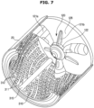
- FIG. 7 is a view illustrating an inside of the tub 20, a drum 310, and the pulsator 120 according to another embodiment of the present disclosure that is not covered by the claimed invention.
- the drum 310 according to the embodiment will be described with reference to FIG. 7 .
- the same components as those in the embodiment shown in FIGS. 1 to 5 are denoted by the same reference numerals and the description thereof will not be repeated.
- the drum 310 may include an agitating protrusion 315 extending in the front and rear direction on the inner circumferential surface of the drum 310 and swollen toward the rotational axis of the drum 310 from the inner circumferential surface of the drum 310.
- the agitating protrusion 315 extends continuously from the front end to the rear end in the front-rear direction of the drum 310, as shown in FIG. 7 , but the present disclosure is not limited thereto and the agitating protrusion 315 may be provided at a portion along the length direction of the drum 310.
- the through holes 311 formed in some parts of the inner circumferential surface of the drum 310 and the protrusions 312 forming the through holes 311 may be omitted, and the agitating protrusion 315 may be formed at the portion where the through holes 311 and the protrusions 312 are omitted.
- the drum 310 since the drum 310 according to the embodiment of the present disclosure includes the agitating protrusion 315, the laundry may be more effectively lifted and dropped.
Landscapes
- Engineering & Computer Science (AREA)
- Textile Engineering (AREA)
- Main Body Construction Of Washing Machines And Laundry Dryers (AREA)
Applications Claiming Priority (2)
| Application Number | Priority Date | Filing Date | Title |
|---|---|---|---|
| KR1020160091051A KR102590137B1 (ko) | 2016-07-18 | 2016-07-18 | 세탁기 |
| PCT/KR2017/005683 WO2018016733A1 (ko) | 2016-07-18 | 2017-05-31 | 세탁기 |
Publications (3)
| Publication Number | Publication Date |
|---|---|
| EP3453795A1 EP3453795A1 (en) | 2019-03-13 |
| EP3453795A4 EP3453795A4 (en) | 2019-07-17 |
| EP3453795B1 true EP3453795B1 (en) | 2024-02-14 |
Family
ID=60993158
Family Applications (1)
| Application Number | Title | Priority Date | Filing Date |
|---|---|---|---|
| EP17831207.0A Active EP3453795B1 (en) | 2016-07-18 | 2017-05-31 | Washing machine |
Country Status (5)
| Country | Link |
|---|---|
| US (1) | US10982371B2 (ko) |
| EP (1) | EP3453795B1 (ko) |
| KR (1) | KR102590137B1 (ko) |
| CN (1) | CN109477279B (ko) |
| WO (1) | WO2018016733A1 (ko) |
Families Citing this family (5)
| Publication number | Priority date | Publication date | Assignee | Title |
|---|---|---|---|---|
| KR102396321B1 (ko) * | 2016-07-12 | 2022-05-10 | 삼성전자주식회사 | 세탁기 |
| JP2021534897A (ja) * | 2018-08-30 | 2021-12-16 | エルジー エレクトロニクス インコーポレイティドLg Electronics Inc. | 洗濯機 |
| KR102598648B1 (ko) * | 2018-08-30 | 2023-11-03 | 엘지전자 주식회사 | 세탁기 및 세탁기의 제어방법 |
| US11773525B2 (en) * | 2019-05-02 | 2023-10-03 | Whirlpool Corporation | Double-rotor washing type drum washing machine |
| DE102020108694A1 (de) * | 2020-03-30 | 2021-09-30 | Miele & Cie. Kg | Verfahren zum Betreiben eines Waschautomaten und Waschautomat |
Citations (4)
| Publication number | Priority date | Publication date | Assignee | Title |
|---|---|---|---|---|
| US20050132556A1 (en) * | 2002-07-03 | 2005-06-23 | Bsh Bosch Und Siemens Hausgerate Gmbh | Washing machine drum |
| US20110088276A1 (en) * | 2005-12-28 | 2011-04-21 | Bsh Bosch Und Siemens Hausgerate Gmbh | Laundry Drum |
| EP2455531A1 (en) * | 2010-11-23 | 2012-05-23 | Vestel Beyaz Esya Sanayi Ve Ticaret A.S. | A drum surface for washing machines |
| CN203420126U (zh) * | 2013-08-13 | 2014-02-05 | 惠而浦(中国)投资有限公司 | 洗衣机的内凹形状脱水孔内筒 |
Family Cites Families (22)
| Publication number | Priority date | Publication date | Assignee | Title |
|---|---|---|---|---|
| FR1227699A (fr) * | 1959-06-17 | 1960-08-22 | Machine à laver à tambour horizontal et à pulsateur intérieur | |
| KR19990042133A (ko) * | 1997-11-25 | 1999-06-15 | 윤종용 | 세탁기 |
| KR20040046911A (ko) * | 2002-11-28 | 2004-06-05 | 엘지전자 주식회사 | 드럼세탁기 |
| KR20050087343A (ko) * | 2004-02-26 | 2005-08-31 | 엘지전자 주식회사 | 펄세이터를 구비한 경사형 드럼세탁기 및 세탁방법 |
| KR101169269B1 (ko) * | 2004-06-21 | 2012-08-02 | 엘지전자 주식회사 | 펄세이터를 구비한 경사형 건조겸용 드럼세탁기 및 그제어방법 |
| KR101169268B1 (ko) * | 2004-06-21 | 2012-08-02 | 엘지전자 주식회사 | 펄세이터를 구비한 경사형 드럼세탁기 및 그 제어방법 |
| KR101128787B1 (ko) * | 2004-06-21 | 2012-03-26 | 엘지전자 주식회사 | 펄세이터를 구비한 경사형 드럼세탁기 및 그 제어방법 |
| US8122547B2 (en) * | 2004-07-20 | 2012-02-28 | Lg Electronics Inc. | Washing machine and method for controlling the same |
| DE102006041431A1 (de) * | 2005-12-07 | 2007-06-14 | Heinz Herbertz | Maschine und Verfahren zum Behandeln von Textilien |
| CN101210367A (zh) * | 2006-12-30 | 2008-07-02 | 苏州三星电子有限公司 | 改进的洗衣机波轮结构 |
| JP4100576B1 (ja) * | 2007-02-14 | 2008-06-11 | 松下電器産業株式会社 | ドラム式洗濯機 |
| WO2009062920A1 (en) * | 2007-11-12 | 2009-05-22 | Arcelik Anonim Sirketi | A washing machine |
| DE102008009141A1 (de) * | 2008-02-14 | 2009-08-27 | BSH Bosch und Siemens Hausgeräte GmbH | Wäschetrommel für eine Wäschebehandlungsmaschine |
| JP2010046323A (ja) | 2008-08-22 | 2010-03-04 | Panasonic Corp | 洗濯乾燥機 |
| CN201538898U (zh) * | 2009-12-03 | 2010-08-04 | 博西威家用电器有限公司 | 衣物处理桶和使用该衣物处理桶的衣物处理设备 |
| US9080279B2 (en) | 2011-10-24 | 2015-07-14 | Lg Electronics Inc. | Washing machine to produce three-dimensional motion |
| US10323350B2 (en) * | 2013-07-19 | 2019-06-18 | Amotech Co., Ltd. | Washing machine motor and washing machine comprising same |
| EP3061861B1 (en) | 2013-10-23 | 2019-06-19 | Haier Group Corporation | Washing method of washing machine and washing machine |
| CN104562545B (zh) * | 2013-10-23 | 2018-07-06 | 青岛海尔洗衣机有限公司 | 洗衣机洗涤方法及其洗衣机 |
| CN103668855A (zh) | 2014-01-15 | 2014-03-26 | 济南大学 | 一种滚筒波轮混合式洗衣机 |
| JP6379436B2 (ja) * | 2014-02-25 | 2018-08-29 | アクア株式会社 | 洗濯機 |
| WO2015158044A1 (zh) * | 2014-04-17 | 2015-10-22 | 无锡小天鹅股份有限公司 | 滚筒洗衣机 |
-
2016
- 2016-07-18 KR KR1020160091051A patent/KR102590137B1/ko active IP Right Grant
-
2017
- 2017-05-31 WO PCT/KR2017/005683 patent/WO2018016733A1/ko unknown
- 2017-05-31 US US16/319,172 patent/US10982371B2/en active Active
- 2017-05-31 CN CN201780043985.8A patent/CN109477279B/zh active Active
- 2017-05-31 EP EP17831207.0A patent/EP3453795B1/en active Active
Patent Citations (4)
| Publication number | Priority date | Publication date | Assignee | Title |
|---|---|---|---|---|
| US20050132556A1 (en) * | 2002-07-03 | 2005-06-23 | Bsh Bosch Und Siemens Hausgerate Gmbh | Washing machine drum |
| US20110088276A1 (en) * | 2005-12-28 | 2011-04-21 | Bsh Bosch Und Siemens Hausgerate Gmbh | Laundry Drum |
| EP2455531A1 (en) * | 2010-11-23 | 2012-05-23 | Vestel Beyaz Esya Sanayi Ve Ticaret A.S. | A drum surface for washing machines |
| CN203420126U (zh) * | 2013-08-13 | 2014-02-05 | 惠而浦(中国)投资有限公司 | 洗衣机的内凹形状脱水孔内筒 |
Also Published As
| Publication number | Publication date |
|---|---|
| CN109477279B (zh) | 2022-02-25 |
| KR102590137B1 (ko) | 2023-10-18 |
| KR20180009285A (ko) | 2018-01-26 |
| US20200149205A1 (en) | 2020-05-14 |
| CN109477279A (zh) | 2019-03-15 |
| WO2018016733A1 (ko) | 2018-01-25 |
| EP3453795A1 (en) | 2019-03-13 |
| EP3453795A4 (en) | 2019-07-17 |
| US10982371B2 (en) | 2021-04-20 |
Similar Documents
| Publication | Publication Date | Title |
|---|---|---|
| EP3453795B1 (en) | Washing machine | |
| US7634926B2 (en) | Mechanism for mounting motor of washing machine and washing machine using the same | |
| US20150211163A1 (en) | Washing machine | |
| US11560664B2 (en) | Washing machine | |
| US11225741B2 (en) | Clothes treating device | |
| US20070028654A1 (en) | Drum washing machine | |
| EP2551398B1 (en) | Motor usable with washing machine and washing machine having the same | |
| KR20130017882A (ko) | 세탁기용 구동장치와 이를 구비한 세탁기 | |
| US10683600B2 (en) | Washing machine | |
| US20180187359A1 (en) | Drum washing machine | |
| US11174580B2 (en) | Washing machine | |
| JP2012170680A (ja) | ドラム式洗濯機 | |
| KR20070115300A (ko) | 드럼세탁기 | |
| KR20160107505A (ko) | 드럼 세탁기 | |
| KR20050089355A (ko) | 대용량 드럼세탁기용 비엘디시 모터 | |
| KR102426575B1 (ko) | 세탁기 | |
| KR101139255B1 (ko) | 세탁기의 모터 | |
| KR20050105839A (ko) | 드럼세탁기 | |
| KR20050119270A (ko) | 드럼세탁기 | |
| KR20090055897A (ko) | 드럼세탁기 | |
| KR20080076057A (ko) | 드럼세탁기 | |
| KR20140101108A (ko) | 세탁기 |
Legal Events
| Date | Code | Title | Description |
|---|---|---|---|
| STAA | Information on the status of an ep patent application or granted ep patent |
Free format text: STATUS: THE INTERNATIONAL PUBLICATION HAS BEEN MADE |
|
| PUAI | Public reference made under article 153(3) epc to a published international application that has entered the european phase |
Free format text: ORIGINAL CODE: 0009012 |
|
| STAA | Information on the status of an ep patent application or granted ep patent |
Free format text: STATUS: REQUEST FOR EXAMINATION WAS MADE |
|
| 17P | Request for examination filed |
Effective date: 20181206 |
|
| AK | Designated contracting states |
Kind code of ref document: A1 Designated state(s): AL AT BE BG CH CY CZ DE DK EE ES FI FR GB GR HR HU IE IS IT LI LT LU LV MC MK MT NL NO PL PT RO RS SE SI SK SM TR |
|
| AX | Request for extension of the european patent |
Extension state: BA ME |
|
| STAA | Information on the status of an ep patent application or granted ep patent |
Free format text: STATUS: REQUEST FOR EXAMINATION WAS MADE |
|
| A4 | Supplementary search report drawn up and despatched |
Effective date: 20190614 |
|
| RIC1 | Information provided on ipc code assigned before grant |
Ipc: D06F 23/02 20060101ALN20190607BHEP Ipc: D06F 37/04 20060101ALI20190607BHEP Ipc: D06F 37/22 20060101ALN20190607BHEP Ipc: D06F 37/06 20060101ALI20190607BHEP Ipc: D06F 17/06 20060101ALN20190607BHEP Ipc: D06F 17/08 20060101ALN20190607BHEP Ipc: D06F 37/40 20060101AFI20190607BHEP |
|
| DAV | Request for validation of the european patent (deleted) | ||
| DAX | Request for extension of the european patent (deleted) | ||
| STAA | Information on the status of an ep patent application or granted ep patent |
Free format text: STATUS: EXAMINATION IS IN PROGRESS |
|
| 17Q | First examination report despatched |
Effective date: 20220311 |
|
| GRAP | Despatch of communication of intention to grant a patent |
Free format text: ORIGINAL CODE: EPIDOSNIGR1 |
|
| STAA | Information on the status of an ep patent application or granted ep patent |
Free format text: STATUS: GRANT OF PATENT IS INTENDED |
|
| RIC1 | Information provided on ipc code assigned before grant |
Ipc: D06F 37/22 20060101ALN20230921BHEP Ipc: D06F 23/02 20060101ALN20230921BHEP Ipc: D06F 17/08 20060101ALN20230921BHEP Ipc: D06F 17/06 20060101ALN20230921BHEP Ipc: D06F 37/04 20060101ALI20230921BHEP Ipc: D06F 37/06 20060101ALI20230921BHEP Ipc: D06F 37/40 20060101AFI20230921BHEP |
|
| INTG | Intention to grant announced |
Effective date: 20231011 |
|
| GRAS | Grant fee paid |
Free format text: ORIGINAL CODE: EPIDOSNIGR3 |
|
| GRAA | (expected) grant |
Free format text: ORIGINAL CODE: 0009210 |
|
| STAA | Information on the status of an ep patent application or granted ep patent |
Free format text: STATUS: THE PATENT HAS BEEN GRANTED |
|
| AK | Designated contracting states |
Kind code of ref document: B1 Designated state(s): AL AT BE BG CH CY CZ DE DK EE ES FI FR GB GR HR HU IE IS IT LI LT LU LV MC MK MT NL NO PL PT RO RS SE SI SK SM TR |
|
| REG | Reference to a national code |
Ref country code: GB Ref legal event code: FG4D |
|
| REG | Reference to a national code |
Ref country code: CH Ref legal event code: EP |
|
| REG | Reference to a national code |
Ref country code: DE Ref legal event code: R096 Ref document number: 602017079202 Country of ref document: DE |
|
| REG | Reference to a national code |
Ref country code: IE Ref legal event code: FG4D |