EP3453664A1 - Climbing elevator transfer system and methods - Google Patents
Climbing elevator transfer system and methods Download PDFInfo
- Publication number
- EP3453664A1 EP3453664A1 EP18190821.1A EP18190821A EP3453664A1 EP 3453664 A1 EP3453664 A1 EP 3453664A1 EP 18190821 A EP18190821 A EP 18190821A EP 3453664 A1 EP3453664 A1 EP 3453664A1
- Authority
- EP
- European Patent Office
- Prior art keywords
- rail
- car
- shuttle
- hoistways
- hoistway
- Prior art date
- Legal status (The legal status is an assumption and is not a legal conclusion. Google has not performed a legal analysis and makes no representation as to the accuracy of the status listed.)
- Granted
Links
Images




Classifications
-
- B—PERFORMING OPERATIONS; TRANSPORTING
- B66—HOISTING; LIFTING; HAULING
- B66B—ELEVATORS; ESCALATORS OR MOVING WALKWAYS
- B66B9/00—Kinds or types of lifts in, or associated with, buildings or other structures
- B66B9/16—Mobile or transportable lifts specially adapted to be shifted from one part of a building or other structure to another part or to another building or structure
-
- B—PERFORMING OPERATIONS; TRANSPORTING
- B66—HOISTING; LIFTING; HAULING
- B66B—ELEVATORS; ESCALATORS OR MOVING WALKWAYS
- B66B9/00—Kinds or types of lifts in, or associated with, buildings or other structures
- B66B9/003—Kinds or types of lifts in, or associated with, buildings or other structures for lateral transfer of car or frame, e.g. between vertical hoistways or to/from a parking position
-
- B—PERFORMING OPERATIONS; TRANSPORTING
- B66—HOISTING; LIFTING; HAULING
- B66B—ELEVATORS; ESCALATORS OR MOVING WALKWAYS
- B66B11/00—Main component parts of lifts in, or associated with, buildings or other structures
- B66B11/04—Driving gear ; Details thereof, e.g. seals
-
- B—PERFORMING OPERATIONS; TRANSPORTING
- B66—HOISTING; LIFTING; HAULING
- B66B—ELEVATORS; ESCALATORS OR MOVING WALKWAYS
- B66B11/00—Main component parts of lifts in, or associated with, buildings or other structures
- B66B11/04—Driving gear ; Details thereof, e.g. seals
- B66B11/0407—Driving gear ; Details thereof, e.g. seals actuated by an electrical linear motor
Definitions
- the disclosure relates to elevator systems. More particularly, the disclosure relates to ropeless elevators wherein the elevator cars are propelled by onboard motors.
- wheel hub motors have been developed for electric automobiles.
- a recent example of a wheel hub motor (also known as in-wheel electric motor) is found in PCT/NL2017/050032 , internationally filed January 19, 2017 and entitled “Wheel Comprising an In-Wheel Electric Motor", published July 27, 2017 as WO2017/126963A1 .
- the disclosure of WO2017/126963A1 (the WO '963 publication) is incorporated by reference herein in its entirety as if set forth at length
- an elevator system comprising a plurality of hoistways, each having at least one rail. At least one car is moveable along and between the plurality of hoistways and has a drive assembly operably connected to the car and including two or more wheels engageable to opposing surfaces of the rail of a hoistway along which the car may move.
- the drive assembly is configured to apply an engagement force to the rail to both support the car at the rail and drive the car along the rail. At least one shuttle is moveable transverse to the plurality of hoistways for transferring the car between the hoistways.
- the drive assembly comprises, for at least a first wheel and a second wheel of said two or more wheels, a wheel hub motor.
- each said wheel comprises a tire mounted to rotate with a rotor of the wheel hub motor.
- each hoistway has a first said rail and a second said rail.
- Each said car has at least: a first pair of wheels oppositely engaged to the first rail and comprising said first wheel and a third wheel; and a second pair of wheels oppositely engaged to the second rail and comprising said second wheel and a fourth wheel.
- the system further comprises at least one device for compressing the first pair of wheels to the first rail and the second pair of wheels to the second rail.
- At least one of the at least one shuttle comprises at least one rail positionable in registry with the rail of one of the hoistways to receive a car from or transfer a car to that hoistway.
- system further comprises a transfer rail, at least one of the at least one shuttle being configured to suspend a car from the transfer rail for movement between the hoistways.
- the shuttle comprises a wheel hub motor to drive the shuttle along the transfer rail.
- system further comprises a track, at least one of the at least one shuttle being supported atop the track.
- the at least one shuttle comprises: a first shuttle at a first level; and a second shuttle at a second level different from the first level.
- the at least one rail for each hoistway, comprises a first rail and a second rail.
- the car has doors only on one side.
- each hoistway has an electrical contact rail and the car has at least one electrical contact shoe for engaging the electrical contact rail for powering the car.
- a method for using the system comprises: driving the car along a first of the hoistways; acquiring the car by the shuttle; moving the shuttle transverse to the hoistways to align the car with a second of the hoistways; and driving the car along the second hoistway.
- the second hoistway comprises a dedicated car maintenance location and the driving along the second hoistway comprises driving to the dedicated maintenance location.
- the acquiring comprises driving the car so that its wheels disengage the opposing surfaces of the rail of the first hoistway and engage opposing surfaces of a rail of the shuttle.
- an elevator system comprising: a first hoistway; a second hoistway; a guide rail including: a first guide rail portion extending along the first hoistway; and a second guide rail portion extending along the second hoistway.
- a transfer rail spans the first hoistway and second hoistway and supports a transfer carriage.
- An elevator car is disposed in and movable along the guide rail; and a drive assembly operably connected to the elevator car and including two or more wheels engaged to opposing surfaces of the rail, the drive assembly configured to apply an engagement force to the rail to both support the elevator car at the rail and drive the elevator car along the rail.
- the elevator car and the drive assembly are configured to allow for travel of the elevator car in a vertical position along the first guide rail portion, and to transfer from the first hoistway to the second hoistway via the transfer carriage.
- the transfer carriage includes a direct drive prime mover to move the transfer carriage along the transfer rail.
- the direct drive prime mover is a wheel hub motor.
- the two or more wheels engage the rail via an engagement force applied by one or more of a spring element, or a mechanical, electrical or hydraulic actuator.
- the rail includes a rail web connected to rail flanges, the wheels disposed on opposing sides of the rail web.
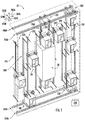
- FIG. 1 shows an elevator system 20 having a group or cluster of hoistways 22A, 22B, 22C, 22D, 22E.
- the hoistways may each span multiple floors of a building.
- the elevator system further includes a plurality of elevator cars 24 movable along and among the hoistways as is discussed below.
- the exemplary cars are single-door cars (i.e., door(s) at only one end of the car which is defined as a front of the car - the rear end ( FIG. 2 ) being closed). In other embodiments, the cars may have any desired configuration of doors.
- a forward direction is shown as 502A
- an aft direction as 502B an upward direction as 500A
- a downward direction 500B and opposite first and second lateral directions as 504A and 504B.
- Each hoistway includes a pair of vertical rails 26A, 26B (e.g., steel).
- the rails extend along a height H R ( FIG. 3 ).
- the height H R may span multiple floors of the building.
- H R is the same and continuous and even (starts and ends at same level).
- H R may be different for some of the hoistways 22A, 22B, 22D, and 22E.
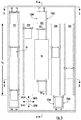
- the exemplary hoistway 22C is segmented with an upper portion 22C 1 and a lower portion 22C 2 ( FIG. 3 ) respectively above and below a vacant space 28 which may form part of the occupied space of the building.
- Other more complex embodiments may do things such as have different heights H R and/or stagger the heights.
- different or staggered heights may serve various purposes such as providing a limited number of elevators with access to upper floors while not wasting the space of extending all the hoistways to said upper floors.
- at the bottom end there may be a limited service to parking garages, basements, and the like.
- Yet further variations can come into play when dealing with transfer situations such as where passengers take one set of elevators up through a lower portion of a building and then transfer to another set.
- one advantage of some implementations may be avoiding the need for transfer between cars.
- the cars 24 are self-propelled. This frees the elevator design from constraints of rope systems. Such constraints include height limitations and the association of specific cars with specific corresponding hoistways. Also, ropeless systems are less sensitive to building sway (e.g., wind or seismic). Also, during large seismic events, roped systems may have problems with ropes coming off pulleys and with damage to relatively light duty stabilizing rollers.
- FIG. 6 shows each rail 26A, 26B as having front face 30A and an aft face 30B.
- the exemplary front and aft faces are front and aft faces of a web of an I-beam that, accordingly, has respective inboard and outboard flanges at opposite ends of the web cross-section.
- Alternate rails may be T-sectioned or may be box-sectioned (hollow).
- Each car includes a drive assembly 40 ( FIG. 2A ) operably connected to the car and including two or more wheels (wheel assemblies) engagable to the faces 30A and 30B to apply an engagement force to the rails to both support the car at the rails and drive the car along the rails.
- a forward pair of wheels 42A, 42B there are four wheels: a forward pair of wheels 42A, 42B; and an aft pair of wheels 42C and 42D (collectively or individually 42).
- the exemplary wheels 42 each comprise a tire 44, a rim/wheel 46, and a wheel hub motor 48.
- the wheels 42 may have friction surface such as a tire mounted directly to or integral with the wheel hub motor 48.
- the first wheels 42A, 42C of each pair engage the first rail 26A of the hoistway and the second wheels 42B, 42D engage the second rail 42B.
- the wheels 42A and 42C may form a first pair engaging opposite faces of the first rail, while the wheels 42B and 42D form a second pair engaging opposite faces of the second rail.
- all four wheels 42 have direct drive prime movers in the form of wheel hub motors 48.
- Alternative embodiments may include motors in only two (e.g., the front wheels 42A, 42B or the back wheels 42C, 42D with the undriven wheels merely serving to stabilize and pinch the rail between the wheels).
- the exemplary FIG. 2A configuration shows the front pair of wheels mounted to a shaft 50A and the aft pair mounted to a shaft 50B.
- the exemplary shafts 50A, 50B are non-rotating shafts providing structural support rather than serving as axles.
- the exemplary shafts are secured against rotation in pillow blocks 52 so that the stator of the wheel hub motor is rigidly non-rotatably connected to the associated shaft.
- the rotor of the wheel hub motor is connected to (e.g., integrated with) the rim 48.
- the exemplary pillow blocks 52 are shown mounted to the top 54 of the car.
- the pillow blocks are slidably mounted fore and aft along a limited range of movement and a tensioning device 56 links adjacent pillow blocks of the fore and aft shafts to each other to apply tension and, in turn, compress the rail between the associated wheels to provide sufficient normal force to avoid slippage.
- the tensioning device 56 may comprise a spring, a hydraulic actuator, a pneumatic actuator, or the like.
- additional safety mechanisms may be provided such as mechanical locking.
- the tensioning device may initially tension and compress the wheels against the rail but then be locked out.
- one of the two pillow blocks in each pair are fixed and the other is slidably mounted.
- the shafts may be rotatably mounted to the car with the pillow blocks as bearings.
- One or both shafts may be integrated with or otherwise driven by the inner rotor of an electric motor (e.g., with the outer stator fixed against rotation)).
- Exemplary tires include solid rubber or other resilient material or pneumatic tires.
- the cars may further be movable among/between the hoistways. This may be accomplished by transfer shuttles or carriages 100, 102.
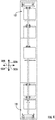
- FIGs. 1 and 4 show one or more lower transfer shuttles 100 as carts 100 at the bottom of the cluster for transferring cars between hoistways.
- FIG. 1 also shows upper transfer shuttles 102 as hanging shuttles 102 at the top of the cluster for transferring cars between hoistways.
- the exemplary carts 100 are wheeled carts riding along a pair of rails 104A, 104B.
- the exemplary hanging shuttles 102 are also wheeled, having wheels riding atop rails 106A, 106B ( FIGs. 1 and 5 ).
- the rails 104A, 104B and 106A, 106B form tracks (e.g., shown as box channel tracks).
- the carts 100 and hanging shuttles 102 may be driven by onboard motors or otherwise controlled (e.g., chain or similar drive).
- Exemplary onboard motors include hub motors such as those described for the wheels 42.
- the transfer shuttles 100, 102 each have a pair of vertical rails 126A, 126B. When a shuttle is in an operative position registered with a given hoistway, these rails align/register with the rails 26A, 26B of the hoistway to allow a car to drive between the hoistway rails and the shuttle rails. Accordingly, the cross-section and spacing of the shuttle rails may be the same as that of the hoistway rails. Once a car has fully transferred to a transfer shuttle, the shuttle may move the car from one hoistway to another and then the car may drive itself off the rails of the shuttle and onto the rails of that hoistway, thereby freeing the shuttle for further use.
- the exemplary system shows multiple hanging shuttles 102 and multiple carts 100, there need not be multiples of each and need not be both types.
- the transfer shuttle tracks are shown as laterally coextensive with the hoistways, there could be different configurations in which one or both of the sets of transfer shuttle tracks extend laterally past the hoistways or do not extend fully across.
- the full number of hoistways may extend along the lower portion of the building and a subgroup may extend the full height.
- the exemplary illustrated configuration shows four full-height hoistways 22A, 22B, 22D, and 22E.
- the hoistway 22C is vertically interrupted.
- the portions of that hoistway beyond the vacant space (dead area) 28 may service a smaller group of floors or may act as locations for purposes such as car maintenance, car storage, and the like.
- the exemplary embodiment shows one such location above the dead space and one such location below the dead space merely for purposes of illustration.
- the hoistways may be isolated from each other via walls such as for fire protection or structural purposes.
- the walls may be load bearing and the rails may be mounted to the walls.
- the rails may be supported front and back via beams extending to front and back walls of the building structure surrounding the cluster.
- the elevators may be powered via conductors (discussed below) running along the shaft and engaged by appropriate conductors (e.g., shoes) on the car.
- conductors discussed below
- One set of possibilities involves embedding the former conductors along the rails.
- Communication may similarly pass through conductors or may be radio frequency via transmit/receive radios (not shown) in each car communicating with one or more radios (not shown) in the hoistway which, in turn, may be hard wire or radio connected to a central controller 200 ( FIG. 1 ) that interfaces with the cars' local controllers 204, the building's control devices (e.g., the elevator buttons and central control console), and the like.
- the transfer shuttles 100, 102 may be similarly powered and controlled.
- Examples of such powering may be via a power rail 220 ( FIG. 6A ) integrated with or parallel to one or both rails (and tracks for the transfer shuttles).
- Multipole conductor rails 220 are available from suppliers in the industrial crane and warehousing fields such as Conductix-Wampfler USA, Omaha, California.
- the multipole rail allows one or more forms of power (e.g., one form for powering the motors and another form for powering lighting, control, communications, climate control, etc.) and control and communication.
- the cars and transfer shuttles have contact shoes 222 complementary to the power rails.
- the transfer shuttle vertical rails may have power (and communication/control) rails 220 just as the hoistway rails. These may receive power and communication/control via the transfer shuttle track power and communication/control rails 220 and transfer shuttle shoes 222.
- each car and shuttle may be a local battery (charged via the rail power) in each car and shuttle to provide emergency operation and continuous operation despite interruptions (e.g., a loss of electrical contact at some particular location in car travel).
- FIG. 1 further shows the central controller 200.
- the central controller may receive user inputs from an input device (e.g., switches, keyboard, or the like) and sensors (not shown, e.g., car position sensors, door position sensors, motor condition sensors, power sensors, and temperature sensors at various system locations).
- the controller may be coupled to the sensors and controllable system components (e.g., transfer shuttle motors, car motors, locking mechanisms, and the like) via control lines 202 (e.g., hardwired or wireless communication paths).
- the controller may include one or more: processors; memory (e.g., for storing program information for execution by the processor to perform the operational methods and for storing data used or generated by the program(s)); and hardware interface devices (e.g., ports) for interfacing with input/output devices and controllable system components.
- processors e.g., for storing program information for execution by the processor to perform the operational methods and for storing data used or generated by the program(s)
- hardware interface devices e.g., ports
- the system may be implemented using existing or yet-developed self-propelled/ropeless elevator technology. As such, materials and manufacture techniques may be drawn from such technologies.
- use of a hub motor and rail systems is one particular implementation.
- use of the same hub motors in the transfer shuttles 100, 102 as in the cars 24 is an option that facilitates economy of scale in manufacture and repair.
- alternatives are possible.
- other self-propelled configurations are relevant including situations where the wheels might be outwardly biased (e.g., against four respective rails or other surfaces along the periphery of the individual hoistway).
- Additional features may relate to the cars going to transfer stations. For example, when a car is otherwise to go to a transfer station, there may be a passenger detection override that prevents the car from leaving the main portion of a hoistway until all passengers have left (but optionally with a service or emergency override allowing technicians or emergency personnel to ride the car into engagement with the transfer shuttle, etc.).
- Control may generally correspond to that set forth in United States Patent Application Publication 20170008729A1, of Ginsberg, et al., January 12, 2017 , the disclosure of which in incorporated by reference in its entirety herein as if set forth at length, and International Application No. PCT/US2016/016528 , internationally filed February 4, 2016, and entitled “Multi-Car Elevator Control", published August 11, 2016 as WO2016/126919A1
- first, second, and the like in the description and following claims is for differentiation within the claim only and does not necessarily indicate relative or absolute importance or temporal order. Similarly, the identification in a claim of one element as “first” (or the like) does not preclude such "first” element from identifying an element that is referred to as “second” (or the like) in another claim or in the description.
Landscapes
- Engineering & Computer Science (AREA)
- Structural Engineering (AREA)
- Civil Engineering (AREA)
- Automation & Control Theory (AREA)
- Mechanical Engineering (AREA)
- Transportation (AREA)
- Lift-Guide Devices, And Elevator Ropes And Cables (AREA)
- Types And Forms Of Lifts (AREA)
Abstract
Description
- Benefit is claimed of
US Patent Application No. 62/555,773 - The disclosure relates to elevator systems. More particularly, the disclosure relates to ropeless elevators wherein the elevator cars are propelled by onboard motors.
-
PCT/US2011/036020 of Shu et al. , internationally filed May 11, 2011 and entitled "Circulation Transport System" discloses a ropeless elevator system (also known as self-propelled elevator system) with horizontal transfer between hoistways. International Application No.PCT/US2016/046120 of Witczak et al. , internationally filed August 9, 2016, and entitled "Configurable Multicar Elevator System" discloses another exemplary ropeless elevator system.US Patent Application Publication 2017/0088395A1 of Roberts et al., filed September 23, 2016 and published March 30, 2017 discloses another ropeless elevator system. - In the distinct automotive propulsion field, wheel hub motors have been developed for electric automobiles. A recent example of a wheel hub motor (also known as in-wheel electric motor) is found in
PCT/NL2017/050032 WO2017/126963A1 . The disclosure ofWO2017/126963A1 (the WO '963 publication) is incorporated by reference herein in its entirety as if set forth at length - One aspect of the disclosure involves an elevator system comprising a plurality of hoistways, each having at least one rail. At least one car is moveable along and between the plurality of hoistways and has a drive assembly operably connected to the car and including two or more wheels engageable to opposing surfaces of the rail of a hoistway along which the car may move. The drive assembly is configured to apply an engagement force to the rail to both support the car at the rail and drive the car along the rail. At least one shuttle is moveable transverse to the plurality of hoistways for transferring the car between the hoistways.
- In one or more embodiments of any of the foregoing embodiments, the drive assembly comprises, for at least a first wheel and a second wheel of said two or more wheels, a wheel hub motor.
- In one or more embodiments of any of the foregoing embodiments, each said wheel comprises a tire mounted to rotate with a rotor of the wheel hub motor.
- In one or more embodiments of any of the foregoing embodiments, each hoistway has a first said rail and a second said rail. Each said car has at least: a first pair of wheels oppositely engaged to the first rail and comprising said first wheel and a third wheel; and a second pair of wheels oppositely engaged to the second rail and comprising said second wheel and a fourth wheel.
- In one or more embodiments of any of the foregoing embodiments, the system further comprises at least one device for compressing the first pair of wheels to the first rail and the second pair of wheels to the second rail.
- In one or more embodiments of any of the foregoing embodiments, at least one of the at least one shuttle comprises at least one rail positionable in registry with the rail of one of the hoistways to receive a car from or transfer a car to that hoistway.
- In one or more embodiments of any of the foregoing embodiments, the system further comprises a transfer rail, at least one of the at least one shuttle being configured to suspend a car from the transfer rail for movement between the hoistways.
- In one or more embodiments of any of the foregoing embodiments, the shuttle comprises a wheel hub motor to drive the shuttle along the transfer rail.
- In one or more embodiments of any of the foregoing embodiments, the system further comprises a track, at least one of the at least one shuttle being supported atop the track.
- In one or more embodiments of any of the foregoing embodiments, the at least one shuttle comprises: a first shuttle at a first level; and a second shuttle at a second level different from the first level.
- In one or more embodiments of any of the foregoing embodiments, for each hoistway, the at least one rail comprises a first rail and a second rail.
- In one or more embodiments of any of the foregoing embodiments, the car has doors only on one side.
- In one or more embodiments of any of the foregoing embodiments, each hoistway has an electrical contact rail and the car has at least one electrical contact shoe for engaging the electrical contact rail for powering the car.
- In one or more embodiments of any of the foregoing embodiments, a method for using the system comprises: driving the car along a first of the hoistways; acquiring the car by the shuttle; moving the shuttle transverse to the hoistways to align the car with a second of the hoistways; and driving the car along the second hoistway.
- In one or more embodiments of any of the foregoing embodiments, the second hoistway comprises a dedicated car maintenance location and the driving along the second hoistway comprises driving to the dedicated maintenance location.
- In one or more embodiments of any of the foregoing embodiments, the acquiring comprises driving the car so that its wheels disengage the opposing surfaces of the rail of the first hoistway and engage opposing surfaces of a rail of the shuttle.
- Another aspect of the disclosure involves an elevator system comprising: a first hoistway; a second hoistway; a guide rail including: a first guide rail portion extending along the first hoistway; and a second guide rail portion extending along the second hoistway. A transfer rail spans the first hoistway and second hoistway and supports a transfer carriage. An elevator car is disposed in and movable along the guide rail; and a drive assembly operably connected to the elevator car and including two or more wheels engaged to opposing surfaces of the rail, the drive assembly configured to apply an engagement force to the rail to both support the elevator car at the rail and drive the elevator car along the rail. The elevator car and the drive assembly are configured to allow for travel of the elevator car in a vertical position along the first guide rail portion, and to transfer from the first hoistway to the second hoistway via the transfer carriage.
- In one or more embodiments of any of the foregoing embodiments, the transfer carriage includes a direct drive prime mover to move the transfer carriage along the transfer rail.
- In one or more embodiments of any of the foregoing embodiments, the direct drive prime mover is a wheel hub motor.
- In one or more embodiments of any of the foregoing embodiments, the two or more wheels engage the rail via an engagement force applied by one or more of a spring element, or a mechanical, electrical or hydraulic actuator.
- In one or more embodiments of any of the foregoing embodiments, the rail includes a rail web connected to rail flanges, the wheels disposed on opposing sides of the rail web.
- The details of one or more embodiments are set forth in the accompanying drawings and the description below. Other features, objects, and advantages will be apparent from the description and drawings, and from the claims.
-
-
FIG. 1 is a front oblique schematic view of an elevator system. -
FIG. 2 is a rear oblique schematic view of the elevator system. -
FIG. 2A is an enlarged view of an upper portion of a car in the elevator system ofFIG. 2 . -
FIG. 3 is an aft view of the elevator system. -
FIG. 4 is a longitudinal vertical sectional view of the elevator system taken along line 4-4 ofFIG. 3 . -
FIG. 5 is a downward sectional view of the elevator system taken along line 5-5 ofFIG. 3 . -
FIG. 6 is a downward sectional view taken along line 6-6 ofFIG. 3 . -
FIG. 6A is an enlarged view of an electric shoe/rail area of the upper portion of a car in the elevator system ofFIG. 6 . - Like reference numbers and designations in the various drawings indicate like elements.
-
FIG. 1 shows anelevator system 20 having a group or cluster ofhoistways elevator cars 24 movable along and among the hoistways as is discussed below. The exemplary cars are single-door cars (i.e., door(s) at only one end of the car which is defined as a front of the car - the rear end (FIG. 2 ) being closed). In other embodiments, the cars may have any desired configuration of doors. Thus, a forward direction is shown as 502A, an aft direction as 502B, an upward direction as 500A, adownward direction 500B, and opposite first and second lateral directions as 504A and 504B. - Each hoistway includes a pair of
vertical rails FIG. 3 ). The height HR may span multiple floors of the building. In the exemplary embodiment, for each of thehoistways hoistways exemplary hoistway 22C is segmented with anupper portion 22C1 and alower portion 22C2 (FIG. 3 ) respectively above and below avacant space 28 which may form part of the occupied space of the building. - Other more complex embodiments may do things such as have different heights HR and/or stagger the heights. For example, different or staggered heights may serve various purposes such as providing a limited number of elevators with access to upper floors while not wasting the space of extending all the hoistways to said upper floors. Similarly, at the bottom end, there may be a limited service to parking garages, basements, and the like. Yet further variations can come into play when dealing with transfer situations such as where passengers take one set of elevators up through a lower portion of a building and then transfer to another set. However, as is discussed below, one advantage of some implementations may be avoiding the need for transfer between cars.
- As is discussed further below, the
cars 24 are self-propelled. This frees the elevator design from constraints of rope systems. Such constraints include height limitations and the association of specific cars with specific corresponding hoistways. Also, ropeless systems are less sensitive to building sway (e.g., wind or seismic). Also, during large seismic events, roped systems may have problems with ropes coming off pulleys and with damage to relatively light duty stabilizing rollers. -
FIG. 6 shows eachrail front face 30A and anaft face 30B. The exemplary front and aft faces are front and aft faces of a web of an I-beam that, accordingly, has respective inboard and outboard flanges at opposite ends of the web cross-section. Alternate rails may be T-sectioned or may be box-sectioned (hollow). - Each car includes a drive assembly 40 (
FIG. 2A ) operably connected to the car and including two or more wheels (wheel assemblies) engagable to thefaces wheels wheels tire 44, a rim/wheel 46, and awheel hub motor 48. In various embodiment, the wheels 42 may have friction surface such as a tire mounted directly to or integral with thewheel hub motor 48. Thefirst wheels first rail 26A of the hoistway and thesecond wheels second rail 42B. Alternatively characterized, thewheels wheels - In the exemplary embodiment, all four wheels 42 have direct drive prime movers in the form of
wheel hub motors 48. Alternative embodiments may include motors in only two (e.g., thefront wheels back wheels FIG. 2A configuration shows the front pair of wheels mounted to ashaft 50A and the aft pair mounted to ashaft 50B. - The
exemplary shafts rim 48. - The exemplary pillow blocks 52 are shown mounted to the top 54 of the car. In one implementation, the pillow blocks are slidably mounted fore and aft along a limited range of movement and a
tensioning device 56 links adjacent pillow blocks of the fore and aft shafts to each other to apply tension and, in turn, compress the rail between the associated wheels to provide sufficient normal force to avoid slippage. Thetensioning device 56 may comprise a spring, a hydraulic actuator, a pneumatic actuator, or the like. When the tensioning device is a controllable actuator, additional safety mechanisms may be provided such as mechanical locking. For example, the tensioning device may initially tension and compress the wheels against the rail but then be locked out. - In other variations, one of the two pillow blocks in each pair (e.g., both pillow blocks of one of the two shafts) are fixed and the other is slidably mounted. Other variations may avoid the wheel hub motors. For example, the shafts may be rotatably mounted to the car with the pillow blocks as bearings. One or both shafts may be integrated with or otherwise driven by the inner rotor of an electric motor (e.g., with the outer stator fixed against rotation)).
- Exemplary tires include solid rubber or other resilient material or pneumatic tires.
- The cars may further be movable among/between the hoistways. This may be accomplished by transfer shuttles or
carriages FIGs. 1 and4 show one or more lower transfer shuttles 100 ascarts 100 at the bottom of the cluster for transferring cars between hoistways.FIG. 1 also shows upper transfer shuttles 102 as hangingshuttles 102 at the top of the cluster for transferring cars between hoistways. Theexemplary carts 100 are wheeled carts riding along a pair ofrails rails FIGs. 1 and5 ). Thus, therails carts 100 and hangingshuttles 102 may be driven by onboard motors or otherwise controlled (e.g., chain or similar drive). Exemplary onboard motors include hub motors such as those described for the wheels 42. - The transfer shuttles 100, 102 each have a pair of
vertical rails rails - Although the exemplary system shows multiple hanging
shuttles 102 andmultiple carts 100, there need not be multiples of each and need not be both types. Additionally, although the transfer shuttle tracks are shown as laterally coextensive with the hoistways, there could be different configurations in which one or both of the sets of transfer shuttle tracks extend laterally past the hoistways or do not extend fully across. As noted above, for example, in a high rise building, it might be possible that there are multiple groups of one or both types of transfer shuttle. For example, the full number of hoistways may extend along the lower portion of the building and a subgroup may extend the full height. There thus could be one set of transfer shuttle tracks and hanging shuttle(s) 102 at the very top covering just the full-height subgroup while another is at the top of the shorter height subgroup that spans just that subgroup. - As noted above, the exemplary illustrated configuration shows four full-
height hoistways hoistway 22C is vertically interrupted. The portions of that hoistway beyond the vacant space (dead area) 28 may service a smaller group of floors or may act as locations for purposes such as car maintenance, car storage, and the like. The exemplary embodiment shows one such location above the dead space and one such location below the dead space merely for purposes of illustration. - Although not illustrated, the hoistways may be isolated from each other via walls such as for fire protection or structural purposes. For example, the walls may be load bearing and the rails may be mounted to the walls. Alternatively, the rails may be supported front and back via beams extending to front and back walls of the building structure surrounding the cluster.
- The elevators may be powered via conductors (discussed below) running along the shaft and engaged by appropriate conductors (e.g., shoes) on the car. One set of possibilities involves embedding the former conductors along the rails. Communication may similarly pass through conductors or may be radio frequency via transmit/receive radios (not shown) in each car communicating with one or more radios (not shown) in the hoistway which, in turn, may be hard wire or radio connected to a central controller 200 (
FIG. 1 ) that interfaces with the cars'local controllers 204, the building's control devices (e.g., the elevator buttons and central control console), and the like. The transfer shuttles 100, 102 may be similarly powered and controlled. - Examples of such powering may be via a power rail 220 (
FIG. 6A ) integrated with or parallel to one or both rails (and tracks for the transfer shuttles).Multipole conductor rails 220 are available from suppliers in the industrial crane and warehousing fields such as Conductix-Wampfler USA, Omaha, Nebraska. The multipole rail allows one or more forms of power (e.g., one form for powering the motors and another form for powering lighting, control, communications, climate control, etc.) and control and communication. The cars and transfer shuttles havecontact shoes 222 complementary to the power rails. - The transfer shuttle vertical rails may have power (and communication/control) rails 220 just as the hoistway rails. These may receive power and communication/control via the transfer shuttle track power and communication/
control rails 220 and transfer shuttle shoes 222. - Also, there may be a local battery (charged via the rail power) in each car and shuttle to provide emergency operation and continuous operation despite interruptions (e.g., a loss of electrical contact at some particular location in car travel).
-
FIG. 1 further shows thecentral controller 200. As noted above, there may be a combination of a central (main or group)controller 200 and local controllers 204 (FIG. 6A ) on each car and transfer shuttle. The central controller may receive user inputs from an input device (e.g., switches, keyboard, or the like) and sensors (not shown, e.g., car position sensors, door position sensors, motor condition sensors, power sensors, and temperature sensors at various system locations). The controller may be coupled to the sensors and controllable system components (e.g., transfer shuttle motors, car motors, locking mechanisms, and the like) via control lines 202 (e.g., hardwired or wireless communication paths). The controller may include one or more: processors; memory (e.g., for storing program information for execution by the processor to perform the operational methods and for storing data used or generated by the program(s)); and hardware interface devices (e.g., ports) for interfacing with input/output devices and controllable system components. - The system may be implemented using existing or yet-developed self-propelled/ropeless elevator technology. As such, materials and manufacture techniques may be drawn from such technologies. As mentioned above, use of a hub motor and rail systems is one particular implementation. Thus, use of the same hub motors in the transfer shuttles 100, 102 as in the
cars 24 is an option that facilitates economy of scale in manufacture and repair. However, alternatives are possible. Although shown with two pairs of wheels pinching two rails, other self-propelled configurations are relevant including situations where the wheels might be outwardly biased (e.g., against four respective rails or other surfaces along the periphery of the individual hoistway). - Additional features may relate to the cars going to transfer stations. For example, when a car is otherwise to go to a transfer station, there may be a passenger detection override that prevents the car from leaving the main portion of a hoistway until all passengers have left (but optionally with a service or emergency override allowing technicians or emergency personnel to ride the car into engagement with the transfer shuttle, etc.).
- Control may generally correspond to that set forth in United States Patent Application Publication
20170008729A1, of Ginsberg, et al., January 12, 2017 , the disclosure of which in incorporated by reference in its entirety herein as if set forth at length, and International Application No.PCT/US2016/016528 , internationally filed February 4, 2016, and entitled "Multi-Car Elevator Control", published August 11, 2016 asWO2016/126919A1 - (the '919 publication) the disclosure of which is incorporated by reference in its entirety herein as if set forth at length.
- The use of "first", "second", and the like in the description and following claims is for differentiation within the claim only and does not necessarily indicate relative or absolute importance or temporal order. Similarly, the identification in a claim of one element as "first" (or the like) does not preclude such "first" element from identifying an element that is referred to as "second" (or the like) in another claim or in the description.
- One or more embodiments have been described. Nevertheless, it will be understood that various modifications may be made. For example, when applied to an existing basic system, details of such configuration or its associated use may influence details of particular implementations. Accordingly, other embodiments are within the scope of the following claims.
Claims (15)
- An elevator system comprising:a plurality of hoistways, each having at least one rail;at least one car moveable along and between the plurality of hoistways and having:a drive assembly operably connected to the car and including two or more wheels engageable to opposing surfaces of the rail of a hoistway along which the car may move, the drive assembly configured to apply an engagement force to the rail to both support the car at the rail and drive the car along the rail; andat least one shuttle moveable transverse to the plurality of hoistways for transferring the car between the hoistways.
- The system of claim 1 wherein the drive assembly comprises:for at least a first wheel and a second wheel of said two or more wheels, a wheel hub motor.
- The system of claim 2 wherein:each said wheel comprises a tire mounted to rotate with a rotor of the wheel hub motor.
- The system of claim 1, 2 or 3 wherein:each hoistway has a first said rail and a second said rail;each said car has at least:a first pair of wheels oppositely engaged to the first rail and comprising said first wheel and a third wheel; anda second pair of wheels oppositely engaged to the second rail and comprising said second wheel and a fourth wheel.
- The system of claim 4 further comprising:at least one device for compressing the first pair of wheels to the first rail and the second pair of wheels to the second rail.
- The system of any preceding claim wherein:at least one of the at least one shuttle comprises at least one rail positionable in registry with the rail of one of the hoistways to receive a car from or transfer a car to that hoistway.
- The system of any preceding claim further comprising:a transfer rail, at least one of the at least one shuttle being configured to suspend a car from the transfer rail for movement between the hoistways.
- The system of claim 7 wherein the shuttle comprises a wheel hub motor to drive the shuttle along the transfer rail.
- The system of any preceding claim further comprising:a track, at least one of the at least one shuttle being supported atop the track.
- The system of any preceding claim wherein:the at least one shuttle comprises:a first shuttle at a first level; anda second shuttle at a second level different from the first level.
- The system of any preceding claim wherein:for each hoistway, the at least one rail comprises a first rail and a second rail.
- The system of any preceding claim wherein:the car has doors only on one side.
- The system of any preceding claim wherein:each hoistway has an electrical contact rail; andthe car has at least one electrical contact shoe for engaging the electrical contact rail for powering the car.
- A method for using the system of any preceding claim, the method comprising:driving the car along a first of the hoistways;acquiring the car by the shuttle;moving the shuttle transverse to the hoistways to align the car with a second of the hoistways; anddriving the car along the second hoistway; and preferably wherein:the acquiring comprises driving the car so that its wheels disengage the opposing surfaces of the rail of the first hoistway and engage opposing surfaces of a rail of the shuttle.
- The method of claim 14 wherein the second hoistway comprises a dedicated car maintenance location and the driving along the second hoistway comprises driving to the dedicated maintenance location.
Applications Claiming Priority (2)
| Application Number | Priority Date | Filing Date | Title |
|---|---|---|---|
| US201762555773P | 2017-09-08 | 2017-09-08 | |
| US15/840,578 US11027944B2 (en) | 2017-09-08 | 2017-12-13 | Climbing elevator transfer system and methods |
Publications (2)
| Publication Number | Publication Date |
|---|---|
| EP3453664A1 true EP3453664A1 (en) | 2019-03-13 |
| EP3453664B1 EP3453664B1 (en) | 2021-10-27 |
Family
ID=63405107
Family Applications (1)
| Application Number | Title | Priority Date | Filing Date |
|---|---|---|---|
| EP18190821.1A Active EP3453664B1 (en) | 2017-09-08 | 2018-08-24 | Climbing elevator transfer system and methods |
Country Status (3)
| Country | Link |
|---|---|
| US (1) | US11027944B2 (en) |
| EP (1) | EP3453664B1 (en) |
| CN (1) | CN109466990B (en) |
Cited By (9)
| Publication number | Priority date | Publication date | Assignee | Title |
|---|---|---|---|---|
| CN110790111A (en) * | 2019-12-02 | 2020-02-14 | 胡杰 | Traction-driven multi-car-shared multi-well circulating operation elevator |
| CN112607557A (en) * | 2020-12-23 | 2021-04-06 | 上海建工四建集团有限公司 | Intelligent circulating type goods elevator system and use method |
| EP3945058A1 (en) * | 2020-07-30 | 2022-02-02 | Otis Elevator Company | Autonomous elevator car movers and traction surfaces therefor, configured with traction increasing and guidance enhancing implements |
| EP3960679A1 (en) * | 2020-08-24 | 2022-03-02 | Otis Elevator Company | System and method for transferring elevator cars from a first elevator shaft to a second elevator shaft |
| CN114455430A (en) * | 2020-11-07 | 2022-05-10 | 奥的斯电梯公司 | Elevator car identification and tracking |
| EP3998224A1 (en) * | 2020-11-07 | 2022-05-18 | Otis Elevator Company | Ropeless elevator propulsion system |
| CN114590681A (en) * | 2020-12-04 | 2022-06-07 | 奥的斯电梯公司 | Elevator car mover configured with auxiliary vehicle support |
| EP4008669A1 (en) * | 2020-12-04 | 2022-06-08 | Otis Elevator Company | Ropeless elevator vehicle workstation |
| EP4008668A1 (en) * | 2020-12-04 | 2022-06-08 | Otis Elevator Company | Autonomous elevator car mover configured for derailment prevention |
Families Citing this family (29)
| Publication number | Priority date | Publication date | Assignee | Title |
|---|---|---|---|---|
| US10752466B2 (en) * | 2014-12-30 | 2020-08-25 | Otis Elevator Company | Transfer station for a ropeless elevator system with redundancy of subcomponents and parking zone |
| DE102015102564A1 (en) * | 2015-02-23 | 2016-08-25 | Thyssenkrupp Ag | Elevator system with several shafts and several cabins and additional cabin receiving shaft |
| WO2017027495A1 (en) * | 2015-08-11 | 2017-02-16 | Otis Elevator Company | Configurable multicar elevator system |
| US11027944B2 (en) * | 2017-09-08 | 2021-06-08 | Otis Elevator Company | Climbing elevator transfer system and methods |
| EP3521232A1 (en) * | 2018-02-02 | 2019-08-07 | KONE Corporation | Electric linear motor |
| CN112311099B (en) * | 2019-07-31 | 2023-08-18 | 湖南大举信息科技有限公司 | Power supply systems for elevators without accompanying cables and multi-car elevator systems |
| BR112022011691A2 (en) * | 2019-12-18 | 2022-09-06 | Inventio Ag | METHOD FOR RAISING AN ELEVATOR INSTALLATION |
| CN111204623A (en) * | 2019-12-20 | 2020-05-29 | 庄平凡 | Elevator system |
| DE102020101114A1 (en) * | 2020-01-17 | 2021-07-22 | MagneCat UG (haftungsbeschränkt) | Tracked vehicle driven by a linear motor |
| US20210221647A1 (en) * | 2020-01-21 | 2021-07-22 | Otis Elevator Company | Climbing elevator with load-based traction force |
| US11390490B2 (en) | 2020-01-21 | 2022-07-19 | Otis Elevator Company | Cantilevered climbing elevator |
| US20220024715A1 (en) * | 2020-07-27 | 2022-01-27 | Otis Elevator Company | Beam climber brake condition-based monitoring system |
| US20220033229A1 (en) * | 2020-07-28 | 2022-02-03 | Otis Elevator Company | Beam climber assembly pod for guide rail and guide beam installation |
| US20220033217A1 (en) * | 2020-07-30 | 2022-02-03 | Otis Elevator Company | Multi-car elevator system with autonomous car movers configured for collision avoidance |
| US11970369B2 (en) * | 2020-07-31 | 2024-04-30 | Otis Elevator Company | Beam climber battery charging in transfer station |
| US20220033218A1 (en) * | 2020-07-31 | 2022-02-03 | Otis Elevator Company | Beam climber friction monitoring system |
| US12434943B2 (en) * | 2020-07-31 | 2025-10-07 | Otis Elevator Company | Beam climber active brake health monitoring system |
| US12528667B2 (en) * | 2020-08-17 | 2026-01-20 | Otis Elevator Company | Autonomous elevator car mover configured for self-learning lateral clearance control |
| US20220055865A1 (en) * | 2020-08-21 | 2022-02-24 | Otis Elevator Company | Autonomous elevator car mover configured with guide wheels |
| US12466697B2 (en) * | 2020-08-24 | 2025-11-11 | Otis Elevator Company | Ropeless elevator robotic transporters for vehicle parking |
| US20220063958A1 (en) * | 2020-08-25 | 2022-03-03 | Otis Elevator Company | Ropeless elevator building to building mobility system |
| US11873191B2 (en) * | 2020-08-31 | 2024-01-16 | Otis Elevator Company | Elevator propulsion device including a power supply arranged to reduce noise in the cab |
| US11524873B2 (en) * | 2020-10-02 | 2022-12-13 | Otis Elevator Company | Ropeless elevator wheel force releasing system |
| US11667497B2 (en) * | 2020-11-04 | 2023-06-06 | Otis Elevator Company | Wall climbing elevator |
| US20220177262A1 (en) * | 2020-12-04 | 2022-06-09 | Otis Elevator Company | Ropeless elevator intelligent normal force release supervisory control |
| CN113998407A (en) * | 2021-11-15 | 2022-02-01 | 中国建筑第八工程局有限公司 | Deep foundation pit earthwork vertical flowing water conveying system and construction method thereof |
| WO2023172745A1 (en) * | 2022-03-10 | 2023-09-14 | Hyprlift, Inc. | Dynamic tractive drive for vertical transportation system |
| CN115973877A (en) * | 2022-12-26 | 2023-04-18 | 中建三局集团有限公司 | A traction system suitable for multi-well cycle operation |
| EP4530242A1 (en) * | 2023-09-29 | 2025-04-02 | Ceilix AG | Lift system for moving people between floors, method of using a lift system and computer implemented method for route-planning for a lift system |
Citations (9)
| Publication number | Priority date | Publication date | Assignee | Title |
|---|---|---|---|---|
| WO2005115906A2 (en) * | 2004-05-26 | 2005-12-08 | Hans Jappsen | Individually-driven lift |
| WO2012038760A2 (en) * | 2010-09-24 | 2012-03-29 | Adrian Michael Godwin | Transportation system |
| WO2016126919A1 (en) | 2015-02-05 | 2016-08-11 | Otis Elevator Company | Multi-car elevator control |
| US20170008729A1 (en) | 2015-07-10 | 2017-01-12 | Otis Elevator Company | Control system for multicar elevator system |
| WO2017027503A1 (en) * | 2015-08-12 | 2017-02-16 | Otis Elevator Company | Transport system for ropeless elevator hoistway and method |
| US20170057784A1 (en) * | 2015-08-25 | 2017-03-02 | Otis Elevator Company | Alignment system for an elevator car |
| US20170088395A1 (en) | 2015-09-25 | 2017-03-30 | Otis Elevator Company | Elevator component separation assurance system and method of operation |
| US20170158461A1 (en) * | 2015-12-04 | 2017-06-08 | Otis Elevator Company | Thrust and moment control system for an elevator system |
| WO2017126963A1 (en) | 2016-01-20 | 2017-07-27 | E-Traction Europe B.V. | Wheel comprising an in-wheel electric motor |
Family Cites Families (52)
| Publication number | Priority date | Publication date | Assignee | Title |
|---|---|---|---|---|
| US134698A (en) * | 1873-01-07 | Improvement in guides for elevators | ||
| US1859483A (en) * | 1929-08-23 | 1932-05-24 | Lenna R Winslow | Elevator |
| DE1151908B (en) | 1957-07-02 | 1963-07-25 | Richard Sauter | Elevator device |
| US3244258A (en) * | 1963-09-11 | 1966-04-05 | Charles G Neidert | Hoisting equipment |
| AT246046B (en) * | 1964-04-13 | 1966-03-25 | Carl-Heinrich Dipl Ing Hagel | Method for introducing, classifying and removing loads in a multi-storey building |
| US3432046A (en) * | 1966-09-08 | 1969-03-11 | Triax Co | Transfer means for a load carrier in a storage system |
| US3658155A (en) * | 1970-09-15 | 1972-04-25 | William G Salter | Elevator system |
| US3866767A (en) * | 1973-02-15 | 1975-02-18 | Rapistan Inc | Mobile tier picking apparatus for a warehousing system |
| DE3939762A1 (en) | 1989-12-01 | 1991-06-06 | Boecker Albert Gmbh & Co Kg | Person and material lift for building sites - in which internal power source and drives toothed belt engaging in vertical toothed poles forming guideway |
| JPH03177290A (en) | 1989-12-06 | 1991-08-01 | Kumarifuto Kk | Elevator |
| US5228820A (en) * | 1990-09-21 | 1993-07-20 | Advanced Technology And Research Corporation | Article handling system with distributed storage |
| JPH05286669A (en) | 1992-04-15 | 1993-11-02 | Mitsubishi Electric Corp | Ropeless linear motor elevator |
| HU213428B (en) * | 1992-10-27 | 1997-06-30 | Inventio Ag | Self propelled device mainly for passanger carriing |
| US5566784A (en) * | 1994-07-08 | 1996-10-22 | Otis Elevator Company | Self-propelled elevator system |
| US5558181A (en) * | 1995-01-04 | 1996-09-24 | Bundo; Mutsuro | Elevator |
| EP0745553A1 (en) * | 1995-06-02 | 1996-12-04 | Inventio Ag | Lift driving unit |
| ZA964045B (en) * | 1995-06-02 | 1996-12-03 | Inventio Ag | Wheel frame for a lift |
| US5799755A (en) * | 1996-11-14 | 1998-09-01 | Otis Elevator Company | Linear motor transfer of cab horizontally between elevator and bogey platforms |
| US7533747B2 (en) * | 2000-01-26 | 2009-05-19 | E-Traction Europe B.V. | Wheel provided with driving means |
| US10957569B2 (en) * | 2002-10-11 | 2021-03-23 | Murata Machinery Ltd. | Access to one or more levels of material storage shelves by an overhead hoist transport vehicle from a single track position |
| JP2006027902A (en) * | 2004-07-15 | 2006-02-02 | Inventio Ag | Lift installation having at least three vertical lift shafts mutually adjacently arranged and method for operating the same lift shafts |
| TWI343357B (en) * | 2004-07-22 | 2011-06-11 | Inventio Ag | Elevator installation with individually movable elevator cars and method for operating such an elevator installation |
| US20060163008A1 (en) * | 2005-01-24 | 2006-07-27 | Michael Godwin | Autonomous linear retarder/motor for safe operation of direct drive gearless, rope-less elevators |
| DE102005049408A1 (en) * | 2005-10-13 | 2007-04-26 | Wittenstein Ag | Self-propelled elevator |
| CN200988717Y (en) | 2006-12-30 | 2007-12-12 | 济南重工股份有限公司 | Car self travel type lift |
| WO2008136692A2 (en) | 2007-05-02 | 2008-11-13 | Maglevvision Corporation | Multi-car cyclic magnetic elevator with gravity linear electric generator/motor |
| EP2070860A1 (en) * | 2007-12-11 | 2009-06-17 | Inventio Ag | Lift system with vertically and horizontally moveable lift cabins |
| CN101875465B (en) | 2009-04-28 | 2012-03-28 | 河南理工大学 | Wireless circulating multi-car elevator and circulating system thereof |
| EP2390220A1 (en) * | 2010-05-28 | 2011-11-30 | Inventio AG | Elevator with roller-pinion drive |
| KR20120133686A (en) | 2011-05-31 | 2012-12-11 | 코리엘리베이터 주식회사 | Circular elevator system using worm elevator |
| CN103502133A (en) | 2011-05-11 | 2014-01-08 | 奥的斯电梯公司 | Circulation transport system |
| NL2007261C2 (en) * | 2011-08-12 | 2013-02-13 | E Traction Europe Bv | In-wheel motor with brake. |
| US10246298B2 (en) * | 2013-12-05 | 2019-04-02 | Otis Elevator Company | Ropeless elevator system |
| WO2015137967A1 (en) * | 2014-03-14 | 2015-09-17 | Otis Elevator Company | Robust startup method for ropeless elevator |
| WO2015178682A1 (en) | 2014-05-20 | 2015-11-26 | 김남영 | Three-way elevator circulation system |
| EP3002243A1 (en) | 2014-09-30 | 2016-04-06 | Inventio AG | Elevator system with individually driven cabins and closed track |
| US10752466B2 (en) * | 2014-12-30 | 2020-08-25 | Otis Elevator Company | Transfer station for a ropeless elevator system with redundancy of subcomponents and parking zone |
| WO2016118443A1 (en) | 2015-01-21 | 2016-07-28 | Otis Elevator Company | Buffering device for multiple-car elevator system |
| WO2016123440A1 (en) * | 2015-01-29 | 2016-08-04 | Otis Elevator Company | Mechanically integrated propulsion guiding unit |
| CN107207196B (en) * | 2015-02-04 | 2021-01-01 | 奥的斯电梯公司 | Elevator system evaluation device |
| EP3106418B1 (en) | 2015-06-17 | 2020-09-30 | KONE Corporation | Solution for displacing an elevator car |
| WO2017027495A1 (en) | 2015-08-11 | 2017-02-16 | Otis Elevator Company | Configurable multicar elevator system |
| DE102015218025B4 (en) * | 2015-09-18 | 2019-12-12 | Thyssenkrupp Ag | elevator system |
| US9598265B1 (en) * | 2015-09-28 | 2017-03-21 | Smart Lifts, Llc | Vertically and horizontally mobile elevator cabins |
| CN108602643A (en) | 2015-11-30 | 2018-09-28 | 通力股份公司 | Adjustable elevator with multiple compartments system |
| NL2016127B1 (en) | 2016-01-20 | 2017-07-25 | E-Traction Europe B V | Wheel for a road vehicle. |
| CN105936459A (en) | 2016-06-23 | 2016-09-14 | 袁望画 | Elevator |
| US10494228B2 (en) * | 2017-02-28 | 2019-12-03 | Otis Elevator Company | Guiding devices for elevator systems having roller guides and motion sensors |
| US11104547B2 (en) * | 2017-05-04 | 2021-08-31 | Ivan Araujo Dayrell | Autonomous mobile lift |
| EP3421407A1 (en) * | 2017-06-16 | 2019-01-02 | Otis Elevator Company | Rope-climbing self propelled elevator system |
| US11027944B2 (en) * | 2017-09-08 | 2021-06-08 | Otis Elevator Company | Climbing elevator transfer system and methods |
| CN109466995B (en) * | 2017-09-08 | 2020-11-27 | 奥的斯电梯公司 | Simple Supported Recirculating Elevator System |
-
2017
- 2017-12-13 US US15/840,578 patent/US11027944B2/en active Active
-
2018
- 2018-08-24 EP EP18190821.1A patent/EP3453664B1/en active Active
- 2018-09-07 CN CN201811042896.4A patent/CN109466990B/en active Active
Patent Citations (9)
| Publication number | Priority date | Publication date | Assignee | Title |
|---|---|---|---|---|
| WO2005115906A2 (en) * | 2004-05-26 | 2005-12-08 | Hans Jappsen | Individually-driven lift |
| WO2012038760A2 (en) * | 2010-09-24 | 2012-03-29 | Adrian Michael Godwin | Transportation system |
| WO2016126919A1 (en) | 2015-02-05 | 2016-08-11 | Otis Elevator Company | Multi-car elevator control |
| US20170008729A1 (en) | 2015-07-10 | 2017-01-12 | Otis Elevator Company | Control system for multicar elevator system |
| WO2017027503A1 (en) * | 2015-08-12 | 2017-02-16 | Otis Elevator Company | Transport system for ropeless elevator hoistway and method |
| US20170057784A1 (en) * | 2015-08-25 | 2017-03-02 | Otis Elevator Company | Alignment system for an elevator car |
| US20170088395A1 (en) | 2015-09-25 | 2017-03-30 | Otis Elevator Company | Elevator component separation assurance system and method of operation |
| US20170158461A1 (en) * | 2015-12-04 | 2017-06-08 | Otis Elevator Company | Thrust and moment control system for an elevator system |
| WO2017126963A1 (en) | 2016-01-20 | 2017-07-27 | E-Traction Europe B.V. | Wheel comprising an in-wheel electric motor |
Cited By (14)
| Publication number | Priority date | Publication date | Assignee | Title |
|---|---|---|---|---|
| CN110790111B (en) * | 2019-12-02 | 2023-08-04 | 胡杰 | Traction-driven multi-lift-car sharing multi-well circulating operation elevator |
| CN110790111A (en) * | 2019-12-02 | 2020-02-14 | 胡杰 | Traction-driven multi-car-shared multi-well circulating operation elevator |
| US11584621B2 (en) | 2020-07-30 | 2023-02-21 | Otis Elevator Company | Autonomous elevator car movers and traction surfaces therefor, configured with traction increasing and guidance enhancing implements |
| EP3945058A1 (en) * | 2020-07-30 | 2022-02-02 | Otis Elevator Company | Autonomous elevator car movers and traction surfaces therefor, configured with traction increasing and guidance enhancing implements |
| EP3960679A1 (en) * | 2020-08-24 | 2022-03-02 | Otis Elevator Company | System and method for transferring elevator cars from a first elevator shaft to a second elevator shaft |
| CN114455430A (en) * | 2020-11-07 | 2022-05-10 | 奥的斯电梯公司 | Elevator car identification and tracking |
| EP3998224A1 (en) * | 2020-11-07 | 2022-05-18 | Otis Elevator Company | Ropeless elevator propulsion system |
| US11673773B2 (en) | 2020-11-07 | 2023-06-13 | Otis Elevator Company | Ropeless elevator propulsion system |
| CN114590681A (en) * | 2020-12-04 | 2022-06-07 | 奥的斯电梯公司 | Elevator car mover configured with auxiliary vehicle support |
| EP4008668A1 (en) * | 2020-12-04 | 2022-06-08 | Otis Elevator Company | Autonomous elevator car mover configured for derailment prevention |
| EP4008670A1 (en) * | 2020-12-04 | 2022-06-08 | Otis Elevator Company | Elevator car mover configured with auxiliary vehicle support for force release control |
| EP4008669A1 (en) * | 2020-12-04 | 2022-06-08 | Otis Elevator Company | Ropeless elevator vehicle workstation |
| US12454441B2 (en) | 2020-12-04 | 2025-10-28 | Otis Elevator Company | Elevator car mover configured with auxiliary vehicle support for force release control |
| CN112607557A (en) * | 2020-12-23 | 2021-04-06 | 上海建工四建集团有限公司 | Intelligent circulating type goods elevator system and use method |
Also Published As
| Publication number | Publication date |
|---|---|
| US11027944B2 (en) | 2021-06-08 |
| US20190077636A1 (en) | 2019-03-14 |
| CN109466990A (en) | 2019-03-15 |
| EP3453664B1 (en) | 2021-10-27 |
| CN109466990B (en) | 2021-12-24 |
Similar Documents
| Publication | Publication Date | Title |
|---|---|---|
| EP3453664B1 (en) | Climbing elevator transfer system and methods | |
| US11407617B2 (en) | Simply-supported recirculating elevator system | |
| CN112299198B (en) | Cableless elevator drive device and multi-car elevator system | |
| WO2019114170A1 (en) | Vehicle lifting mechanism and automatic power conversion system | |
| US10875743B2 (en) | Rope-climbing self propelled elevator system | |
| KR101549365B1 (en) | Apparatus for moving container cargo | |
| KR20110053468A (en) | Transport device to reposition the elevator body | |
| CN111204623A (en) | Elevator system | |
| CN207449912U (en) | A kind of bogie and with its Rail Transit System | |
| US20080223666A1 (en) | Traction Arrangements | |
| HK1215236A1 (en) | Self-propelled cargo lift for elevator systems | |
| JP3091587B2 (en) | Vertical and horizontal moving elevator | |
| KR101021977B1 (en) | Branching and joining device for PET vehicle | |
| CN107207195B (en) | Assembly for actuating an elevator car brake | |
| EP4008669B1 (en) | Ropeless elevator vehicle workstation | |
| CN110723049A (en) | Scraper type discharging device for inhaul cable | |
| US20160137458A1 (en) | Transportation system | |
| JP2737743B2 (en) | Vehicle entry / exit device for flat reciprocating parking facilities | |
| CN204174989U (en) | A kind of drive unit of multi-storied garage carrier | |
| CN111132887B (en) | Cables or similar transport equipment and vehicles suitable for such equipment | |
| CN105173981A (en) | Safe and reliable traction-type passenger elevator and safety control method thereof | |
| RU2834493C2 (en) | Shunting device | |
| CN105464437B (en) | Parking lot intelligent scheduling servo | |
| CN214985322U (en) | Suspension type light rail traffic system | |
| JPH0645007Y2 (en) | Traverse carriage drive for multi-level parking system |
Legal Events
| Date | Code | Title | Description |
|---|---|---|---|
| PUAI | Public reference made under article 153(3) epc to a published international application that has entered the european phase |
Free format text: ORIGINAL CODE: 0009012 |
|
| STAA | Information on the status of an ep patent application or granted ep patent |
Free format text: STATUS: THE APPLICATION HAS BEEN PUBLISHED |
|
| AK | Designated contracting states |
Kind code of ref document: A1 Designated state(s): AL AT BE BG CH CY CZ DE DK EE ES FI FR GB GR HR HU IE IS IT LI LT LU LV MC MK MT NL NO PL PT RO RS SE SI SK SM TR |
|
| AX | Request for extension of the european patent |
Extension state: BA ME |
|
| STAA | Information on the status of an ep patent application or granted ep patent |
Free format text: STATUS: REQUEST FOR EXAMINATION WAS MADE |
|
| 17P | Request for examination filed |
Effective date: 20190913 |
|
| RBV | Designated contracting states (corrected) |
Designated state(s): AL AT BE BG CH CY CZ DE DK EE ES FI FR GB GR HR HU IE IS IT LI LT LU LV MC MK MT NL NO PL PT RO RS SE SI SK SM TR |
|
| STAA | Information on the status of an ep patent application or granted ep patent |
Free format text: STATUS: EXAMINATION IS IN PROGRESS |
|
| 17Q | First examination report despatched |
Effective date: 20191219 |
|
| GRAP | Despatch of communication of intention to grant a patent |
Free format text: ORIGINAL CODE: EPIDOSNIGR1 |
|
| STAA | Information on the status of an ep patent application or granted ep patent |
Free format text: STATUS: GRANT OF PATENT IS INTENDED |
|
| INTG | Intention to grant announced |
Effective date: 20201207 |
|
| GRAJ | Information related to disapproval of communication of intention to grant by the applicant or resumption of examination proceedings by the epo deleted |
Free format text: ORIGINAL CODE: EPIDOSDIGR1 |
|
| STAA | Information on the status of an ep patent application or granted ep patent |
Free format text: STATUS: EXAMINATION IS IN PROGRESS |
|
| INTC | Intention to grant announced (deleted) | ||
| GRAP | Despatch of communication of intention to grant a patent |
Free format text: ORIGINAL CODE: EPIDOSNIGR1 |
|
| STAA | Information on the status of an ep patent application or granted ep patent |
Free format text: STATUS: GRANT OF PATENT IS INTENDED |
|
| INTG | Intention to grant announced |
Effective date: 20210528 |
|
| GRAS | Grant fee paid |
Free format text: ORIGINAL CODE: EPIDOSNIGR3 |
|
| GRAA | (expected) grant |
Free format text: ORIGINAL CODE: 0009210 |
|
| STAA | Information on the status of an ep patent application or granted ep patent |
Free format text: STATUS: THE PATENT HAS BEEN GRANTED |
|
| AK | Designated contracting states |
Kind code of ref document: B1 Designated state(s): AL AT BE BG CH CY CZ DE DK EE ES FI FR GB GR HR HU IE IS IT LI LT LU LV MC MK MT NL NO PL PT RO RS SE SI SK SM TR |
|
| REG | Reference to a national code |
Ref country code: GB Ref legal event code: FG4D |
|
| REG | Reference to a national code |
Ref country code: CH Ref legal event code: EP |
|
| REG | Reference to a national code |
Ref country code: AT Ref legal event code: REF Ref document number: 1441616 Country of ref document: AT Kind code of ref document: T Effective date: 20211115 |
|
| REG | Reference to a national code |
Ref country code: DE Ref legal event code: R096 Ref document number: 602018025582 Country of ref document: DE |
|
| REG | Reference to a national code |
Ref country code: IE Ref legal event code: FG4D |
|
| REG | Reference to a national code |
Ref country code: LT Ref legal event code: MG9D |
|
| REG | Reference to a national code |
Ref country code: NL Ref legal event code: MP Effective date: 20211027 |
|
| REG | Reference to a national code |
Ref country code: AT Ref legal event code: MK05 Ref document number: 1441616 Country of ref document: AT Kind code of ref document: T Effective date: 20211027 |
|
| PG25 | Lapsed in a contracting state [announced via postgrant information from national office to epo] |
Ref country code: RS Free format text: LAPSE BECAUSE OF FAILURE TO SUBMIT A TRANSLATION OF THE DESCRIPTION OR TO PAY THE FEE WITHIN THE PRESCRIBED TIME-LIMIT Effective date: 20211027 Ref country code: LT Free format text: LAPSE BECAUSE OF FAILURE TO SUBMIT A TRANSLATION OF THE DESCRIPTION OR TO PAY THE FEE WITHIN THE PRESCRIBED TIME-LIMIT Effective date: 20211027 Ref country code: FI Free format text: LAPSE BECAUSE OF FAILURE TO SUBMIT A TRANSLATION OF THE DESCRIPTION OR TO PAY THE FEE WITHIN THE PRESCRIBED TIME-LIMIT Effective date: 20211027 Ref country code: BG Free format text: LAPSE BECAUSE OF FAILURE TO SUBMIT A TRANSLATION OF THE DESCRIPTION OR TO PAY THE FEE WITHIN THE PRESCRIBED TIME-LIMIT Effective date: 20220127 Ref country code: AT Free format text: LAPSE BECAUSE OF FAILURE TO SUBMIT A TRANSLATION OF THE DESCRIPTION OR TO PAY THE FEE WITHIN THE PRESCRIBED TIME-LIMIT Effective date: 20211027 |
|
| PG25 | Lapsed in a contracting state [announced via postgrant information from national office to epo] |
Ref country code: IS Free format text: LAPSE BECAUSE OF FAILURE TO SUBMIT A TRANSLATION OF THE DESCRIPTION OR TO PAY THE FEE WITHIN THE PRESCRIBED TIME-LIMIT Effective date: 20220227 Ref country code: SE Free format text: LAPSE BECAUSE OF FAILURE TO SUBMIT A TRANSLATION OF THE DESCRIPTION OR TO PAY THE FEE WITHIN THE PRESCRIBED TIME-LIMIT Effective date: 20211027 Ref country code: PT Free format text: LAPSE BECAUSE OF FAILURE TO SUBMIT A TRANSLATION OF THE DESCRIPTION OR TO PAY THE FEE WITHIN THE PRESCRIBED TIME-LIMIT Effective date: 20220228 Ref country code: PL Free format text: LAPSE BECAUSE OF FAILURE TO SUBMIT A TRANSLATION OF THE DESCRIPTION OR TO PAY THE FEE WITHIN THE PRESCRIBED TIME-LIMIT Effective date: 20211027 Ref country code: NO Free format text: LAPSE BECAUSE OF FAILURE TO SUBMIT A TRANSLATION OF THE DESCRIPTION OR TO PAY THE FEE WITHIN THE PRESCRIBED TIME-LIMIT Effective date: 20220127 Ref country code: NL Free format text: LAPSE BECAUSE OF FAILURE TO SUBMIT A TRANSLATION OF THE DESCRIPTION OR TO PAY THE FEE WITHIN THE PRESCRIBED TIME-LIMIT Effective date: 20211027 Ref country code: LV Free format text: LAPSE BECAUSE OF FAILURE TO SUBMIT A TRANSLATION OF THE DESCRIPTION OR TO PAY THE FEE WITHIN THE PRESCRIBED TIME-LIMIT Effective date: 20211027 Ref country code: HR Free format text: LAPSE BECAUSE OF FAILURE TO SUBMIT A TRANSLATION OF THE DESCRIPTION OR TO PAY THE FEE WITHIN THE PRESCRIBED TIME-LIMIT Effective date: 20211027 Ref country code: GR Free format text: LAPSE BECAUSE OF FAILURE TO SUBMIT A TRANSLATION OF THE DESCRIPTION OR TO PAY THE FEE WITHIN THE PRESCRIBED TIME-LIMIT Effective date: 20220128 Ref country code: ES Free format text: LAPSE BECAUSE OF FAILURE TO SUBMIT A TRANSLATION OF THE DESCRIPTION OR TO PAY THE FEE WITHIN THE PRESCRIBED TIME-LIMIT Effective date: 20211027 |
|
| REG | Reference to a national code |
Ref country code: DE Ref legal event code: R097 Ref document number: 602018025582 Country of ref document: DE |
|
| PG25 | Lapsed in a contracting state [announced via postgrant information from national office to epo] |
Ref country code: SM Free format text: LAPSE BECAUSE OF FAILURE TO SUBMIT A TRANSLATION OF THE DESCRIPTION OR TO PAY THE FEE WITHIN THE PRESCRIBED TIME-LIMIT Effective date: 20211027 Ref country code: SK Free format text: LAPSE BECAUSE OF FAILURE TO SUBMIT A TRANSLATION OF THE DESCRIPTION OR TO PAY THE FEE WITHIN THE PRESCRIBED TIME-LIMIT Effective date: 20211027 Ref country code: RO Free format text: LAPSE BECAUSE OF FAILURE TO SUBMIT A TRANSLATION OF THE DESCRIPTION OR TO PAY THE FEE WITHIN THE PRESCRIBED TIME-LIMIT Effective date: 20211027 Ref country code: EE Free format text: LAPSE BECAUSE OF FAILURE TO SUBMIT A TRANSLATION OF THE DESCRIPTION OR TO PAY THE FEE WITHIN THE PRESCRIBED TIME-LIMIT Effective date: 20211027 Ref country code: DK Free format text: LAPSE BECAUSE OF FAILURE TO SUBMIT A TRANSLATION OF THE DESCRIPTION OR TO PAY THE FEE WITHIN THE PRESCRIBED TIME-LIMIT Effective date: 20211027 Ref country code: CZ Free format text: LAPSE BECAUSE OF FAILURE TO SUBMIT A TRANSLATION OF THE DESCRIPTION OR TO PAY THE FEE WITHIN THE PRESCRIBED TIME-LIMIT Effective date: 20211027 |
|
| PLBE | No opposition filed within time limit |
Free format text: ORIGINAL CODE: 0009261 |
|
| STAA | Information on the status of an ep patent application or granted ep patent |
Free format text: STATUS: NO OPPOSITION FILED WITHIN TIME LIMIT |
|
| 26N | No opposition filed |
Effective date: 20220728 |
|
| PG25 | Lapsed in a contracting state [announced via postgrant information from national office to epo] |
Ref country code: AL Free format text: LAPSE BECAUSE OF FAILURE TO SUBMIT A TRANSLATION OF THE DESCRIPTION OR TO PAY THE FEE WITHIN THE PRESCRIBED TIME-LIMIT Effective date: 20211027 |
|
| PG25 | Lapsed in a contracting state [announced via postgrant information from national office to epo] |
Ref country code: SI Free format text: LAPSE BECAUSE OF FAILURE TO SUBMIT A TRANSLATION OF THE DESCRIPTION OR TO PAY THE FEE WITHIN THE PRESCRIBED TIME-LIMIT Effective date: 20211027 |
|
| PG25 | Lapsed in a contracting state [announced via postgrant information from national office to epo] |
Ref country code: MC Free format text: LAPSE BECAUSE OF FAILURE TO SUBMIT A TRANSLATION OF THE DESCRIPTION OR TO PAY THE FEE WITHIN THE PRESCRIBED TIME-LIMIT Effective date: 20211027 |
|
| REG | Reference to a national code |
Ref country code: CH Ref legal event code: PL |
|
| GBPC | Gb: european patent ceased through non-payment of renewal fee |
Effective date: 20220824 |
|
| PG25 | Lapsed in a contracting state [announced via postgrant information from national office to epo] |
Ref country code: LU Free format text: LAPSE BECAUSE OF NON-PAYMENT OF DUE FEES Effective date: 20220824 Ref country code: LI Free format text: LAPSE BECAUSE OF NON-PAYMENT OF DUE FEES Effective date: 20220831 Ref country code: CH Free format text: LAPSE BECAUSE OF NON-PAYMENT OF DUE FEES Effective date: 20220831 |
|
| REG | Reference to a national code |
Ref country code: BE Ref legal event code: MM Effective date: 20220831 |
|
| PG25 | Lapsed in a contracting state [announced via postgrant information from national office to epo] |
Ref country code: IT Free format text: LAPSE BECAUSE OF FAILURE TO SUBMIT A TRANSLATION OF THE DESCRIPTION OR TO PAY THE FEE WITHIN THE PRESCRIBED TIME-LIMIT Effective date: 20211027 |
|
| PG25 | Lapsed in a contracting state [announced via postgrant information from national office to epo] |
Ref country code: IE Free format text: LAPSE BECAUSE OF NON-PAYMENT OF DUE FEES Effective date: 20220824 |
|
| PG25 | Lapsed in a contracting state [announced via postgrant information from national office to epo] |
Ref country code: BE Free format text: LAPSE BECAUSE OF NON-PAYMENT OF DUE FEES Effective date: 20220831 |
|
| PG25 | Lapsed in a contracting state [announced via postgrant information from national office to epo] |
Ref country code: GB Free format text: LAPSE BECAUSE OF NON-PAYMENT OF DUE FEES Effective date: 20220824 |
|
| PG25 | Lapsed in a contracting state [announced via postgrant information from national office to epo] |
Ref country code: HU Free format text: LAPSE BECAUSE OF FAILURE TO SUBMIT A TRANSLATION OF THE DESCRIPTION OR TO PAY THE FEE WITHIN THE PRESCRIBED TIME-LIMIT; INVALID AB INITIO Effective date: 20180824 |
|
| PG25 | Lapsed in a contracting state [announced via postgrant information from national office to epo] |
Ref country code: CY Free format text: LAPSE BECAUSE OF FAILURE TO SUBMIT A TRANSLATION OF THE DESCRIPTION OR TO PAY THE FEE WITHIN THE PRESCRIBED TIME-LIMIT Effective date: 20211027 |
|
| PG25 | Lapsed in a contracting state [announced via postgrant information from national office to epo] |
Ref country code: MK Free format text: LAPSE BECAUSE OF FAILURE TO SUBMIT A TRANSLATION OF THE DESCRIPTION OR TO PAY THE FEE WITHIN THE PRESCRIBED TIME-LIMIT Effective date: 20211027 |
|
| PG25 | Lapsed in a contracting state [announced via postgrant information from national office to epo] |
Ref country code: TR Free format text: LAPSE BECAUSE OF FAILURE TO SUBMIT A TRANSLATION OF THE DESCRIPTION OR TO PAY THE FEE WITHIN THE PRESCRIBED TIME-LIMIT Effective date: 20211027 |
|
| PG25 | Lapsed in a contracting state [announced via postgrant information from national office to epo] |
Ref country code: MT Free format text: LAPSE BECAUSE OF FAILURE TO SUBMIT A TRANSLATION OF THE DESCRIPTION OR TO PAY THE FEE WITHIN THE PRESCRIBED TIME-LIMIT Effective date: 20211027 |
|
| PGFP | Annual fee paid to national office [announced via postgrant information from national office to epo] |
Ref country code: DE Payment date: 20250724 Year of fee payment: 8 |
|
| PGFP | Annual fee paid to national office [announced via postgrant information from national office to epo] |
Ref country code: FR Payment date: 20250723 Year of fee payment: 8 |