EP3453661A1 - Sheet processing apparatus - Google Patents
Sheet processing apparatus Download PDFInfo
- Publication number
- EP3453661A1 EP3453661A1 EP18187697.0A EP18187697A EP3453661A1 EP 3453661 A1 EP3453661 A1 EP 3453661A1 EP 18187697 A EP18187697 A EP 18187697A EP 3453661 A1 EP3453661 A1 EP 3453661A1
- Authority
- EP
- European Patent Office
- Prior art keywords
- sheet
- conveyance
- roller
- processing
- pinch roller
- Prior art date
- Legal status (The legal status is an assumption and is not a legal conclusion. Google has not performed a legal analysis and makes no representation as to the accuracy of the status listed.)
- Withdrawn
Links
Images






Classifications
-
- B—PERFORMING OPERATIONS; TRANSPORTING
- B65—CONVEYING; PACKING; STORING; HANDLING THIN OR FILAMENTARY MATERIAL
- B65H—HANDLING THIN OR FILAMENTARY MATERIAL, e.g. SHEETS, WEBS, CABLES
- B65H29/00—Delivering or advancing articles from machines; Advancing articles to or into piles
- B65H29/38—Delivering or advancing articles from machines; Advancing articles to or into piles by movable piling or advancing arms, frames, plates, or like members with which the articles are maintained in face contact
- B65H29/42—Members rotated about an axis parallel to direction of article movement, e.g. helices
-
- B—PERFORMING OPERATIONS; TRANSPORTING
- B65—CONVEYING; PACKING; STORING; HANDLING THIN OR FILAMENTARY MATERIAL
- B65H—HANDLING THIN OR FILAMENTARY MATERIAL, e.g. SHEETS, WEBS, CABLES
- B65H29/00—Delivering or advancing articles from machines; Advancing articles to or into piles
- B65H29/26—Delivering or advancing articles from machines; Advancing articles to or into piles by dropping the articles
- B65H29/34—Delivering or advancing articles from machines; Advancing articles to or into piles by dropping the articles from supports slid from under the articles
-
- B—PERFORMING OPERATIONS; TRANSPORTING
- B65—CONVEYING; PACKING; STORING; HANDLING THIN OR FILAMENTARY MATERIAL
- B65H—HANDLING THIN OR FILAMENTARY MATERIAL, e.g. SHEETS, WEBS, CABLES
- B65H29/00—Delivering or advancing articles from machines; Advancing articles to or into piles
- B65H29/20—Delivering or advancing articles from machines; Advancing articles to or into piles by contact with rotating friction members, e.g. rollers, brushes, or cylinders
-
- B—PERFORMING OPERATIONS; TRANSPORTING
- B65—CONVEYING; PACKING; STORING; HANDLING THIN OR FILAMENTARY MATERIAL
- B65H—HANDLING THIN OR FILAMENTARY MATERIAL, e.g. SHEETS, WEBS, CABLES
- B65H29/00—Delivering or advancing articles from machines; Advancing articles to or into piles
- B65H29/12—Delivering or advancing articles from machines; Advancing articles to or into piles by means of the nip between two, or between two sets of, moving tapes or bands or rollers
- B65H29/14—Delivering or advancing articles from machines; Advancing articles to or into piles by means of the nip between two, or between two sets of, moving tapes or bands or rollers and introducing into a pile
-
- B—PERFORMING OPERATIONS; TRANSPORTING
- B65—CONVEYING; PACKING; STORING; HANDLING THIN OR FILAMENTARY MATERIAL
- B65H—HANDLING THIN OR FILAMENTARY MATERIAL, e.g. SHEETS, WEBS, CABLES
- B65H29/00—Delivering or advancing articles from machines; Advancing articles to or into piles
- B65H29/58—Article switches or diverters
- B65H29/60—Article switches or diverters diverting the stream into alternative paths
-
- B—PERFORMING OPERATIONS; TRANSPORTING
- B65—CONVEYING; PACKING; STORING; HANDLING THIN OR FILAMENTARY MATERIAL
- B65H—HANDLING THIN OR FILAMENTARY MATERIAL, e.g. SHEETS, WEBS, CABLES
- B65H31/00—Pile receivers
- B65H31/02—Pile receivers with stationary end support against which pile accumulates
-
- B—PERFORMING OPERATIONS; TRANSPORTING
- B65—CONVEYING; PACKING; STORING; HANDLING THIN OR FILAMENTARY MATERIAL
- B65H—HANDLING THIN OR FILAMENTARY MATERIAL, e.g. SHEETS, WEBS, CABLES
- B65H31/00—Pile receivers
- B65H31/30—Arrangements for removing completed piles
- B65H31/3009—Arrangements for removing completed piles by dropping, e.g. removing the pile support from under the pile
- B65H31/3018—Arrangements for removing completed piles by dropping, e.g. removing the pile support from under the pile from opposite part-support elements, e.g. operated simultaneously
-
- B—PERFORMING OPERATIONS; TRANSPORTING
- B65—CONVEYING; PACKING; STORING; HANDLING THIN OR FILAMENTARY MATERIAL
- B65H—HANDLING THIN OR FILAMENTARY MATERIAL, e.g. SHEETS, WEBS, CABLES
- B65H31/00—Pile receivers
- B65H31/30—Arrangements for removing completed piles
- B65H31/3027—Arrangements for removing completed piles by the nip between moving belts or rollers
-
- B—PERFORMING OPERATIONS; TRANSPORTING
- B65—CONVEYING; PACKING; STORING; HANDLING THIN OR FILAMENTARY MATERIAL
- B65H—HANDLING THIN OR FILAMENTARY MATERIAL, e.g. SHEETS, WEBS, CABLES
- B65H31/00—Pile receivers
- B65H31/30—Arrangements for removing completed piles
- B65H31/3081—Arrangements for removing completed piles by acting on edge of the pile for moving it along a surface, e.g. by pushing
-
- B—PERFORMING OPERATIONS; TRANSPORTING
- B65—CONVEYING; PACKING; STORING; HANDLING THIN OR FILAMENTARY MATERIAL
- B65H—HANDLING THIN OR FILAMENTARY MATERIAL, e.g. SHEETS, WEBS, CABLES
- B65H31/00—Pile receivers
- B65H31/34—Apparatus for squaring-up piled articles
- B65H31/36—Auxiliary devices for contacting each article with a front stop as it is piled
-
- B—PERFORMING OPERATIONS; TRANSPORTING
- B65—CONVEYING; PACKING; STORING; HANDLING THIN OR FILAMENTARY MATERIAL
- B65H—HANDLING THIN OR FILAMENTARY MATERIAL, e.g. SHEETS, WEBS, CABLES
- B65H43/00—Use of control, checking, or safety devices, e.g. automatic devices comprising an element for sensing a variable
-
- G—PHYSICS
- G03—PHOTOGRAPHY; CINEMATOGRAPHY; ANALOGOUS TECHNIQUES USING WAVES OTHER THAN OPTICAL WAVES; ELECTROGRAPHY; HOLOGRAPHY
- G03G—ELECTROGRAPHY; ELECTROPHOTOGRAPHY; MAGNETOGRAPHY
- G03G15/00—Apparatus for electrographic processes using a charge pattern
- G03G15/65—Apparatus which relate to the handling of copy material
- G03G15/6529—Transporting
-
- B—PERFORMING OPERATIONS; TRANSPORTING
- B65—CONVEYING; PACKING; STORING; HANDLING THIN OR FILAMENTARY MATERIAL
- B65H—HANDLING THIN OR FILAMENTARY MATERIAL, e.g. SHEETS, WEBS, CABLES
- B65H2301/00—Handling processes for sheets or webs
- B65H2301/40—Type of handling process
- B65H2301/42—Piling, depiling, handling piles
- B65H2301/421—Forming a pile
- B65H2301/4212—Forming a pile of articles substantially horizontal
-
- B—PERFORMING OPERATIONS; TRANSPORTING
- B65—CONVEYING; PACKING; STORING; HANDLING THIN OR FILAMENTARY MATERIAL
- B65H—HANDLING THIN OR FILAMENTARY MATERIAL, e.g. SHEETS, WEBS, CABLES
- B65H2301/00—Handling processes for sheets or webs
- B65H2301/40—Type of handling process
- B65H2301/42—Piling, depiling, handling piles
- B65H2301/421—Forming a pile
- B65H2301/4213—Forming a pile of a limited number of articles, e.g. buffering, forming bundles
-
- B—PERFORMING OPERATIONS; TRANSPORTING
- B65—CONVEYING; PACKING; STORING; HANDLING THIN OR FILAMENTARY MATERIAL
- B65H—HANDLING THIN OR FILAMENTARY MATERIAL, e.g. SHEETS, WEBS, CABLES
- B65H2404/00—Parts for transporting or guiding the handled material
- B65H2404/10—Rollers
- B65H2404/15—Roller assembly, particular roller arrangement
- B65H2404/152—Arrangement of roller on a movable frame
- B65H2404/1521—Arrangement of roller on a movable frame rotating, pivoting or oscillating around an axis, e.g. parallel to the roller axis
-
- B—PERFORMING OPERATIONS; TRANSPORTING
- B65—CONVEYING; PACKING; STORING; HANDLING THIN OR FILAMENTARY MATERIAL
- B65H—HANDLING THIN OR FILAMENTARY MATERIAL, e.g. SHEETS, WEBS, CABLES
- B65H2405/00—Parts for holding the handled material
- B65H2405/10—Cassettes, holders, bins, decks, trays, supports or magazines for sheets stacked substantially horizontally
- B65H2405/11—Parts and details thereof
- B65H2405/111—Bottom
- B65H2405/1115—Bottom with surface inclined, e.g. in width-wise direction
- B65H2405/11151—Bottom with surface inclined, e.g. in width-wise direction with surface inclined upwardly in transport direction
-
- B—PERFORMING OPERATIONS; TRANSPORTING
- B65—CONVEYING; PACKING; STORING; HANDLING THIN OR FILAMENTARY MATERIAL
- B65H—HANDLING THIN OR FILAMENTARY MATERIAL, e.g. SHEETS, WEBS, CABLES
- B65H2511/00—Dimensions; Position; Numbers; Identification; Occurrences
- B65H2511/10—Size; Dimensions
-
- B—PERFORMING OPERATIONS; TRANSPORTING
- B65—CONVEYING; PACKING; STORING; HANDLING THIN OR FILAMENTARY MATERIAL
- B65H—HANDLING THIN OR FILAMENTARY MATERIAL, e.g. SHEETS, WEBS, CABLES
- B65H2511/00—Dimensions; Position; Numbers; Identification; Occurrences
- B65H2511/30—Numbers, e.g. of windings or rotations
-
- B—PERFORMING OPERATIONS; TRANSPORTING
- B65—CONVEYING; PACKING; STORING; HANDLING THIN OR FILAMENTARY MATERIAL
- B65H—HANDLING THIN OR FILAMENTARY MATERIAL, e.g. SHEETS, WEBS, CABLES
- B65H2511/00—Dimensions; Position; Numbers; Identification; Occurrences
- B65H2511/40—Identification
- B65H2511/414—Identification of mode of operation
-
- B—PERFORMING OPERATIONS; TRANSPORTING
- B65—CONVEYING; PACKING; STORING; HANDLING THIN OR FILAMENTARY MATERIAL
- B65H—HANDLING THIN OR FILAMENTARY MATERIAL, e.g. SHEETS, WEBS, CABLES
- B65H2801/00—Application field
- B65H2801/24—Post -processing devices
- B65H2801/27—Devices located downstream of office-type machines
-
- B—PERFORMING OPERATIONS; TRANSPORTING
- B65—CONVEYING; PACKING; STORING; HANDLING THIN OR FILAMENTARY MATERIAL
- B65H—HANDLING THIN OR FILAMENTARY MATERIAL, e.g. SHEETS, WEBS, CABLES
- B65H37/00—Article or web delivery apparatus incorporating devices for performing specified auxiliary operations
- B65H37/04—Article or web delivery apparatus incorporating devices for performing specified auxiliary operations for securing together articles or webs, e.g. by adhesive, stitching or stapling
Definitions
- Embodiments described herein relate generally to a sheet processing apparatus.
- a sheet processing apparatus executes a post-processing such as sorting and stapling on a sheet-like image receiving medium (hereinafter, referred to as a "sheet") conveyed from an image forming apparatus.
- the sheet processing apparatus includes a standby section, a processing section, and a discharge section.
- the standby section temporarily retains the sheet.
- the standby section sends the retained sheet to the processing section at a prescribed timing.
- the processing section executes the post-processing by aligning the sheet received from the standby section.
- the processing section discharges the sheet subjected to the post-processing to the discharge section.
- the processing section extrudes an edge of the sheet on an upstream side in a conveyance direction towards a downstream side in the conveyance direction with an extruding member.
- an extruding member bends.
- the processing section sandwiches the sheet between a pinch roller and a conveyance roller to convey the sheet by the rotation of the pinch roller and the conveyance roller.
- the pinch roller and the conveying roller could slide against the sheet.
- One of the objects of the present invention is to improve prior art techniques and overcome at least some of the prior art problems as for instance above illustrated.
- a sheet processing apparatus comprising:
- the controller is configured to apply a force towards the second position to the pinch roller when the sheet is conveyed by the pinch roller and the conveyance roller.
- the controller is configured to switch a selection between a roller discharge process for conveying the sheet only with the pinch roller and the conveyance roller and a combined discharge process for conveying the sheet with the pinch roller, the conveyance roller and the extruder, and the controller is configured to switch the selection based on whether a number of sheets is less than a predetermined value.
- the controller is configured to switch a selection between a roller discharge process for conveying the sheet only with the pinch roller and the conveyance roller and a combined discharge process for conveying the sheet with the pinch roller, the conveyance roller and the extruder, and the controller is configured to switch the selection based on whether a number of sheets is less than a predetermined value.
- the controller is configured to switch a selection between the roller discharge process or the combined discharge process and an extrusion discharge process for conveying the sheet only by the extruder, based on whether a sheet size is less than a threshold value (it is noted that the switching between the roller discharge process and the combined discharge process can be made based on whether a number of sheets is less than a predetermined value and/or whether a sheet size is less than a threshold value).
- the controller is configured to drive the conveyance roller to rotate in the sheet conveyance direction prior to conveyance of the sheet by the extruder.
- the controller is configured to drive the conveyance roller to rotate in the sheet conveyance direction prior to conveyance of the sheet by the extruder.
- the conveyance roller is configured to convey the sheet in the conveyance direction along a conveyance path, wherein the conveyance path includes a first conveyance path, a second conveyance path, and a third conveyance path, the first and second conveyance paths being bifurcated from the first conveyance path.
- the first conveyance path is arranged to guide the sheet to a standby section
- the second conveyance path is configured to guide the sheet to a discharger
- the third conveyance path is arranged to guide the sheet to the processing tray.
- the first position is a standby position and the second position is a rotational position.
- a sheet processing method comprising:
- the sheet processing method according to the second aspect of the invention further comprises applying a force towards the second position to the pinch roller when the sheet is conveyed by the pinch roller and the conveyance roller.
- the sheet processing method further comprises switching a selection between a roller discharge process for conveying the sheet only with the pinch roller and the conveyance roller and a combined discharge process for conveying the sheet with the pinch roller, the conveyance roller and the extruder, wherein the switching is performed based on whether a number of sheets is less than a predetermined value.
- the sheet processing method further comprises switching a selection between a roller discharge process for conveying the sheet only with the pinch roller and the conveyance roller and a combined discharge process for conveying the sheet with the pinch roller, the conveyance roller and the extruder, wherein the switching is performed based on whether a number of sheets is less than a predetermined value.
- the sheet processing method further comprises switching a selection between the roller discharge process or the combined discharge process and an extrusion discharge process for conveying the sheet only by the extruder, based on whether a sheet size is less than a threshold value (it is noted that the switching between the roller discharge process and the combined discharge process can be made based on whether a number of sheets is less than a predetermined value and/or whether a sheet size is less than a threshold value).
- the sheet processing method according to the second aspect further comprises driving the conveyance roller to rotate in the sheet conveyance direction prior to conveyance of the sheet by the extruder.
- the sheet processing method according to the second aspect further comprises driving the conveyance roller to rotate in the sheet conveyance direction prior to conveyance of the sheet by the extruder.
- the sheet processing method further comprises conveying, by the conveyance roller, the sheet in the conveyance direction along a conveyance path, wherein the conveyance path includes a first conveyance path, a second conveyance path, and a third conveyance path, the first and second conveyance paths being bifurcated from the first conveyance path.
- a sheet processing apparatus comprises a processing tray; a conveyance roller, arranged on a downstream side in a sheet conveyance direction with respect to the processing tray, configured to convey a sheet towards the downstream side in the sheet conveyance direction; a pinch roller configured to move between a standby position (an example of a first position) away (e.g.
- a rotational position (an example of a second position) close (or proximate) to the conveyance roller, and to sandwich the sheet with the conveyance roller at the rotational position when the sheet is conveyed by the conveyance roller; an extruding member configured to extrude an upstream end of the sheet in the sheet conveyance direction from the upstream side towards the downstream side in the sheet conveyance direction to convey the sheet placed on the processing tray; and a controller configured to control the conveyance roller, the pinch roller and the extruding member in such a manner as to move the pinch roller to the rotational position if the sheet placed on the processing tray is conveyed to the downstream side in the sheet conveyance direction, move the pinch roller to the standby position after the sheet is conveyed by the pinch roller and the conveyance roller, and then convey the sheet with the extruding member.
- Fig. 1 is a diagram schematically exemplifying the overall configuration of an image forming system 1 according to the embodiment.
- Fig. 2 is a block diagram exemplifying the functional components of an image forming apparatus 2 and a sheet processing apparatus 3 according to the embodiment.
- the image forming system 1 is provided with the image forming apparatus 2 and the sheet processing apparatus 3.
- the image forming apparatus 2 forms an image on a sheet-like medium (hereinafter, collectively referred to as a "sheet S") such as a paper.
- the sheet processing apparatus 3 executes a post-processing on the sheet S discharged from the image forming apparatus 2.
- the image forming apparatus 2 includes a control panel 11, a scanner section (a scanner) 12, a printer section (a printer) 13, a sheet feed section (a feeder) 14, a sheet discharge section (a discharger) 15 and an image forming controller 16.
- the control panel 11 includes an operation section, a display section and a panel controller.
- the operation section receives an operation by a user.
- the operation section includes various keys and a touch panel.
- the display section displays various information.
- the panel controller controls reception of an operation by the user on the operation section and display on the display section.
- the panel controller includes a control circuit having a CPU (Central Processing Unit), a ROM (Read Only Memory), and a RAM (Random Access Memory) .
- the control circuit may carry out operations according to program-executable instructions stored in a non-transitory memory.
- control panel 11 receives an input relating to the sheet S such as a size (sheet size) of the sheet S and the type of the sheet S.
- the sheet size includes a regular size and an irregular size.
- the type of the sheet S includes a paper quality, a quantity, a thickness, and the like.
- the control panel 11 receives an input relating to the type of the post-processing carried out on the sheet S.
- the control panel 11 receives a selection of any one of a plurality of different processing modes.
- the plurality of different processing modes includes a sorting mode, a stapling mode and a non-sorting mode.
- the sorting mode refers to a processing mode in which a sorting process is executed.
- the stapling mode refers to a processing mode in which a binding process (stapling process) by a staple is executed.
- the non-sorting mode refers to a processing mode in which the execution of the sorting process and the stapling process is prohibited.
- the control panel 11 receives an input relating to the number of sheets S (the number of stapled sheets) forming a sheet bundle SS.
- the control panel 11 receives selection of any one of a plurality of discharge destinations for the sheet S.
- the plurality of discharge destinations includes a fixed tray 23a and a movable tray 23b described later.
- the image forming apparatus 2 sends the information relating to the sheet S and the information relating to the type of the post-processing received by the control panel 11 to the sheet processing apparatus 3.
- the scanner section 12 includes a reading section and a scanner controller.
- the reading section reads image information which is a copy object as intensity of light.
- the scanner controller controls reading of the image information by the reading section.
- the scanner controller includes a control circuit having a CPU, a ROM, and a RAM.
- the scanner section 12 sends the read image information to the printer section 13.
- the printer section 13 forms an output image (hereinafter, referred to as a "toner image") with a developer such as a toner based on the image information received from the scanner section 12 or an external device.
- the printer section 13 transfers the toner image onto the surface of the sheet S.
- the printer section 13 applies heat and pressure to the toner image on the surface of the sheet S to fix the toner image on the sheet S.
- the printer section 13 sends the sheet S on which the toner image is fixed to the sheet discharge section 15.
- the printer section 13 includes a printer controller.
- the printer controller includes a control circuit having a CPU, a ROM, and a RAM. The printer controller controls the printing of the image on the sheet S by the printer section 13.
- the sheet feed section 14 supplies the sheets S one by one to the printer section 13 in accordance with a timing at which the printer section 13 forms the toner image.
- the sheet feed section 14 includes a plurality of the sheet feed cassettes.
- Each of the sheet feed cassettes accommodates a sheet S of a predetermined size and type in advance.
- Each of the sheet feed cassettes has a pickup roller.
- Each pickup roller picks up the sheets S one by one from each of the sheet feed cassettes .
- Each pickup roller sends the sheet S taken out from each of the sheet feed cassettes to the printer section 13.
- the sheet discharge section 15 conveys the sheet S received from the printer section 13 to the sheet processing apparatus 3.
- the image forming controller 16 controls the whole operations of the image forming apparatus 2.
- the image forming controller 16 controls the control panel 11, the scanner section 12, the printer section 13, the sheet feed section 14 and the sheet discharge section 15.
- the image forming controller 16 includes, for example, a CPU, a ROM and a RAM.
- the sheet processing apparatus 3 is arranged adjacently to the image forming apparatus 2.
- the sheet processing apparatus 3 executes the post-processing designated via the control panel 11 on the sheet S conveyed from the image forming apparatus 2.
- the post-processing is the sorting process, the stapling process, or the like.
- the sheet processing apparatus 3 includes a standby section 21, a processing section 22, a discharge section 23, a conveyance section 24, a post-processing controller 25, a bundle claw driving mechanism 61, and a pinch roller driving mechanism 71.
- the standby section 21 temporarily retains the sheet S received from the image forming apparatus 2. For example, a plurality of succeeding sheets S stands by on the standby section 21 while the post-processing is executed on the former sheet S by the processing section 22.
- the standby section 21 is arranged above the processing section 22 in a vertical direction. A plurality of sheets S overlaps in a thickness direction and stands by on the standby section 21. If the processing section 22 is in a state capable of receiving the sheet S, the standby section 21 drops the sheet S that is being retained towards the processing section 22.
- the processing section 22 carries out the post-processing on the sheet S received from the standby section 21.
- the processing section 22 carries out the sorting process for gathering a plurality of sheets S and then aligning them.
- the processing section 22 carries out the binding process (stapling process) with a staple on the sheet bundle SS formed by gathering a plurality of sheets S.
- the processing section 22 discharges the sheet S on which the post-processing is carried out to the discharge section 23.
- the discharge section 23 supports the sheet S received from the standby section 21 and the processing section 22.
- the discharge section 23 includes the fixed tray 23a and the movable tray 23b.
- the fixed tray 23a is arranged at the upper part of the sheet processing apparatus 3.
- the movable tray 23b is arranged on the side of the sheet processing apparatus 3.
- the movable tray 23b moves in an upper and lower direction along the side of the sheet processing apparatus 3.
- the upper and lower direction is the vertical direction.
- the fixed tray 23a and the movable tray 23b support the sheet S received from the standby section 21 and the processing section 22.
- the conveyance section 24 includes a conveyance path 31, an inlet roller mechanism 32, and an outlet roller mechanism 33.
- the conveyance path 31 is provided inside the sheet processing apparatus 3.
- the conveyance path 31 guides the sheet S received from the image forming apparatus 2 to the standby section 21, the processing section 22, or the discharge section 23.
- the conveyance path 31 includes a first conveyance path 31a, a second conveyance path 31b and a third conveyance path 31c which bifurcate from the first conveyance path 31a.
- the first conveyance path 31a guides the sheet S to the standby section 21.
- the second conveyance path 31b guides the sheet S to the fixed tray 23a of the discharge section 23.
- the third conveyance path 31c guides the sheet S to the processing section 22.
- the inlet roller mechanism 32 is arranged between the upstream end of the conveyance path 31 in the sheet conveyance direction and the sheet discharge section 15 of the image forming apparatus 2.
- the inlet roller mechanism 32 sends the sheet S received from the image forming apparatus 2 to the conveyance path 31.
- the outlet roller mechanism 33 is arranged between the downstream end of the first conveyance path 31a in the sheet conveyance direction and the standby section 21.
- the outlet roller mechanism 33 sends the sheet S received from the first conveyance path 31a to the standby section 21.
- the post-processing controller 25 controls the whole operations of the sheet processing apparatus 3.
- the post-processing controller 25 controls the standby section 21, the processing section 22, the discharge section 23, the conveyance section 24, the bundle claw driving mechanism 61, and the pinch roller driving mechanism 71.
- the post-processing controller 25 includes a control circuit having a CPU, a ROM, and a RAM.
- Fig. 3 is a side view schematically exemplifying the configuration of the sheet processing apparatus 3 according to the embodiment.
- the conveyance section 24 includes the conveyance path 31 where a sheet supply port 31d and a sheet discharge port 31e are formed.
- the sheet supply port 31d is formed to face the sheet discharge section 15 of the image forming apparatus 2 at the upstream end of the conveyance path 31 in the sheet conveyance direction.
- the sheet S discharged from the image forming apparatus 2 is sent to the conveyance path 31 through the sheet supply port 31d.
- the sheet discharge port 31e is formed to face the standby section 21 at the downstream end of the first conveyance path 31a in the sheet conveyance direction.
- the sheet S passing through the first conveyance path 31a is sent to the standby section 21 through the sheet discharge port 31e.
- the first conveyance path 31a guides the sheet S to the standby section 21 through the sheet supply port 31d if the sorting mode or the stapling mode is selected.
- the second conveyance path 31b guides the sheet S to the fixed tray 23a if the fixed tray 23a of the discharge section 23 is selected as the discharge destination of the sheet S in the non-sorting mode.
- the third conveyance path 31c guides the sheet S directly to the processing section 22 if the movable tray 23b of the discharge section 23 is selected as the discharge destination of the sheet S in the non-sorting mode.
- the third conveyance path 31c may enable the sheet S to pass through the standby section 21 without retaining the sheet S in the standby section 21, when guiding the sheet S directly to the processing section 22.
- the inlet roller mechanism 32 of the conveyance section 24 includes a first inlet roller 32a and a second inlet roller 32b.
- the first inlet roller 32a and the second inlet roller 32b are opposed to each other in a radial direction thereof with rotation axes parallel to each other.
- the first inlet roller 32a is a driven roller disposed on the upper surface side of the conveyance path 31.
- the second inlet roller 32b is a driving roller arranged on the lower surface side of the conveyance path 31.
- the first inlet roller 32a is driven to rotate by a rotational driving force transmitted from the second inlet roller 32b directly or via the sheet S.
- the first inlet roller 32a and the second inlet roller 32b sandwich the sheet S from both sides in the thickness direction of the sheet S at a nip therebetween.
- the first inlet roller 32a and the second inlet roller 32b convey the sheet S that is sandwiched at the nip to the downstream side in the sheet conveyance direction.
- the outlet roller mechanism 33 of the conveyance section 24 comprises a first outlet roller 33a and a second outlet roller 33b.
- the first outlet roller 33a and the second outlet roller 33b are opposed to each other in the radial direction thereof with rotation axes parallel to each other.
- the first outlet roller 33a is a driven roller disposed on the upper surface side of the first conveyance path 31a.
- the second outlet roller 33b is a driving roller disposed on the lower surface side of the first conveyance path 31a.
- the first outlet roller 33a is driven to rotate by a rotational driving force transmitted from the second outlet roller 33b directly or via the sheet S.
- the first outlet roller 33a and the second outlet roller 33b sandwich the sheet S from both sides in the thickness direction of the sheet S at a nip therebetween.
- the first outlet roller 33a and the second outlet roller 33b convey the sheet S that is sandwiched at the nip to the downstream side in the sheet conveyance direction.
- the standby section 21 includes a standby tray 41, an assist guide 43, and a paddle section 45.
- the sheet conveyance direction in the standby section 21 is indicated by a first arrow D1 shown in Fig. 3 .
- the direction indicated by the first arrow D1 is an approach direction of the sheet S from the first outlet roller 33a and the second outlet roller 33b to the standby tray 41.
- the upstream end in the sheet conveyance direction of the standby tray 41 is arranged adjacently to the first outlet roller 33a and the second outlet roller 33b.
- the upstream end of the standby tray 41 is arranged below the sheet discharge port 31e of the conveyance path 31 in the vertical direction.
- the standby tray 41 is tilted with respect to the horizontal direction in such a manner that the downstream side gradually rises vertically upwards with respect to the upstream side as it proceeds from the upstream side to the downstream side in the sheet conveyance direction.
- a plurality of sheets S is stacked in the thickness direction on the standby tray 41 and stands by while the processing section 22 performs the post-processing on the former sheet S.
- the standby tray 41 includes a pair of tray members moving in mutually opposite directions in a sheet width direction.
- the sheet width direction is parallel to a plane of the sheet S and perpendicular to the sheet conveyance direction.
- the pair of the tray members moves towards each other to support the sheet S if the sheet S stands by on the standby tray 41.
- the pair of the tray members moves away from each other to release the support of the sheet S.
- the pair of the tray members drops the sheet S towards the processing section 22 by moving away from each other and then releasing the support of the sheet S.
- the assist guide 43 is arranged above the standby tray 41 in the vertical direction.
- the length of the assist guide 43 in the sheet conveyance direction is the same as that of the standby tray 41 in the sheet conveyance direction.
- the assist guide 43 presses the sheet S towards the processing section 22 in a case of moving the sheet S from the standby tray 41 to the processing section 22.
- the assist guide 43 has a swing shaft parallel to the sheet width direction at the downstream end of the sheet conveyance direction.
- the upstream end of the assist guide 43 in the sheet conveyance direction is swung around the swing shaft.
- the upstream end of the assist guide 43 in the sheet conveyance direction is swung downwards to abut against the sheet S in a case of pressing the sheet S towards the processing section 22.
- the paddle section 45 is arranged between the upstream end of the standby tray 41 and the processing section 22.
- the paddle section 45 includes a rotation axis parallel to the sheet width direction and a paddle 45a rotating around the rotation axis.
- the paddle 45a is made of an elastic material such as rubber.
- the paddle section 45a rotates around the rotation axis while contacting with the sheet S when the sheet S is moved from the standby tray 41 to the processing section 22.
- the paddle section 45a rotates in a counterclockwise direction shown in Fig. 3 .
- the paddle 45a moves the sheet S falling down to the processing section 22 from the standby tray 41 towards the upstream end of the processing section 22 in the sheet conveyance direction.
- the paddle 45a enables the sheet S to contact with the upstream end of the processing section 22 in the sheet conveyance direction to align the position of the rear end of the sheet S in the sheet conveyance direction.
- the paddle 45a aligns the position of the sheet S in the sheet conveyance direction in the processing section 22 (that is, the paddle 45a causes the position of the sheet S to be in a longitudinal alignment).
- the paddle section 45 together with a conveyance roller 59 and a rear end stopper 54 of the processing section 22 described later, constitutes a longitudinal alignment device which performs the longitudinal alignment of the sheet S in the sheet conveyance direction.
- the processing section 22 includes a processing tray 51, a pair of horizontal alignment plates 52, the rear end stopper 54, a stapler 55, an ejector 56, a thruster 56a, a bundle claw 57, a bundle claw belt 58, and the conveyance roller 59.
- the sheet conveyance direction in the processing section 22 is indicated by a second arrow D2 shown in Fig. 3 .
- the direction of the second arrow D2 is a discharge direction of the sheet S from the processing tray 51.
- the processing tray 51 is arranged below the standby tray 41 in the vertical direction.
- the processing tray 51 is tilted with respect to a horizontal direction in such a manner that the downstream side thereof gradually rises upwards in the vertical direction with respect to the upstream side thereof as it goes from the upstream side to the downstream side in the sheet conveyance direction.
- the processing tray 51 is arranged in parallel with the standby tray 41.
- the processing tray 51 includes a conveyance surface 51a on which the sheet S is placed.
- the conveyance surface 51a supports the sheet S.
- the pair of the horizontal alignment plates 52 is arranged away from each other in the sheet width direction at the conveyance surface 51a of the processing tray 51.
- the pair of the horizontal alignment plates 52 moves in mutually opposite directions in the sheet width direction.
- the pair of the horizontal alignment plates 52 aligns the positions of both ends in the sheet width direction of the sheet S by moving towards each other and sandwiching the sheet S from both sides in the sheet width direction.
- the pair of the horizontal alignment plates 52 aligns the position of the sheet S in the sheet width direction (i.e., in a horizontal alignment).
- the pair of the horizontal alignment plates 52 moves away from each other at the time of releasing the clamping of the sheet S.
- the rear end stopper 54 is arranged at the end in the sheet conveyance direction of the processing tray 51.
- the shape of the rear end stopper 54 is a hook shape.
- the rear end stopper 54 supports the rear end in the sheet conveyance direction of the sheet S placed on the processing tray 51.
- the stapler 55 is a binding section which executes the binding process with the staple on the sheet bundle SS formed by aligning a plurality of the sheets S.
- the stapler 55 is arranged at the rear side of the upstream end in the sheet conveyance direction of the processing tray 51.
- a plurality of the sheets S is supported by the rear end stopper 54 and the positions of the rear ends thereof are aligned, and then the rear ends of the plurality of the sheets are tightened by the stapler 55 to be fixed. If the stapling mode is selected, the stapler 55 executes the stapling process on the sheet bundle SS, which is supported by the rear end stopper 54 and of which the rear end thereof is aligned.
- the ejector 56 is arranged at the upstream end of the processing tray 51 in the sheet conveyance direction.
- the ejector 56 is arranged so as to overlap with the rear end stopper 54 if viewed from the sheet width direction at a reference position.
- the shape of the ejector 56 is a hook shape.
- the ejector 56 supports the rear end in the sheet conveyance direction of the sheet bundle SS subjected to the stapling process and the sorting process.
- the ejector 56 moves to the sheet conveyance direction with respect to the processing tray 51.
- the ejector 56 moves from the reference position towards the downstream side in the sheet conveyance direction by a driving force transmitted from a driving source.
- the ejector 56 moves to the reference position by a returning force towards the upstream side in the sheet conveyance direction applied by an elastic member.
- the ejector 56 moves from the upstream side to the downstream side in the sheet conveyance direction while supporting the sheet bundle SS and moves the sheet bundle SS towards the downstream side in the sheet conveyance direction.
- the ejector 56 moves the end of the sheet bundle SS to a position where the sheet bundle SS is delivered to the bundle claw 57.
- the thruster 56a is arranged along the conveyance surface 51a.
- the shape of the thruster 56a is a plate shape.
- the thruster 56a moves in the sheet conveyance direction together with the ejector 56.
- the thruster 56a is arranged on the upstream side in the sheet conveyance direction with respect to the conveyance roller 59. If moving towards the downstream side in the sheet conveyance direction from the reference position, the tip of the thruster 56a in the sheet conveyance direction projects towards the downstream side in the sheet conveyance direction with respect to the conveyance roller 59.
- the thruster 56a protrudes towards the downstream side in the sheet conveyance direction with respect to the conveyance roller 59 so as to extend the conveyance surface 51a towards the downstream side in the sheet conveyance direction.
- the thruster 56a contacts with the lower surface of the sheet S protruding towards the downstream side in the sheet conveyance direction with respect to the conveyance roller 59 to support the sheet S.
- the bundle claw 57 is an extruding member (extruder) that extrudes the sheet bundle SS on the processing tray 51 towards the downstream side in the sheet conveyance direction to move the sheet bundle SS.
- the bundle claw 57 is fixed to the bundle claw belt 58.
- the shape of the bundle claw 57 may be hook shape, for example.
- the bundle claw belt 58 is wound around a pair of a first belt roller 58a and a second belt roller 58b which are arranged apart from each other in the sheet conveyance direction of the processing tray 51.
- the first belt roller 58a is arranged at the downstream side in the sheet conveyance direction with respect to the second belt roller 58b.
- the first belt roller 58a is a driving roller and rotationally drives the bundle claw belt 58.
- the second belt roller 58b is a driven roller and is driven to rotate by a rotational driving force transmitted from the first belt roller 58a via the bundle claw belt 58.
- the bundle claw 57 moves as the bundle claw belt 58 rotates.
- the bundle claw 57 contacts with the rear end in the sheet conveyance direction of the sheet bundle SS placed on the processing tray 51 and conveys the sheet bundle SS in such a manner that it extrudes the sheet bundle SS towards the downstream side in the sheet conveyance direction.
- the bundle claw 57 stands by at a position in front of the second belt roller 56b in an opposite direction to the sheet conveyance direction as a home position HP at the lower surface side of the processing tray 51. Whether the bundle claw 57 is present at the home position HP is detected by a sensor.
- the bundle claw 57 moves from the home position HP towards the second belt roller 58b at the lower surface side of the processing tray 51 as the bundle claw belt 58 rotates in a forward direction.
- the forward rotation of the bundle claw belt 58 is a counterclockwise rotation as shown in Fig. 3 .
- the bundle claw 57 moves along the outer periphery of the second belt roller 58b from the lower surface side to the upper surface side of the processing tray 51.
- the upper surface side of the processing tray 51 is the conveyance surface 51a side.
- the bundle claw 57 receives the sheet bundle SS from the ejector 56 and moves towards the downstream side in the sheet conveyance direction.
- the bundle claw 57 moves along the outer periphery of the first belt roller 58a towards the lower surface side of the processing tray 51 while conveying the sheet bundle SS.
- the bundle claw 57 extrudes the sheet bundle SS towards the downstream side to discharge the sheet bundle SS.
- the bundle claw 57 moves towards the upstream side in the sheet conveyance direction at the upper surface side of the processing tray 51 as the bundle claw belt 58 rotates reversely after the discharge of the sheet bundle SS.
- the bundle claw 57 moves along the outer periphery of the second belt roller 58b from the upper surface side to the lower surface side of the processing tray 51 to return to the home position HP.
- the bundle claw belt 58, the first belt roller 58a and the second belt roller 58b constitute the bundle claw driving mechanism 61 for driving the bundle claw 57.
- the bundle claw driving mechanism 61 is provided with a bundle claw drive motor 62.
- the bundle claw drive motor 62 is a driving source for the first belt roller 58a, the ejector 56, and the thruster 56a.
- the bundle claw drive motor 62 is always connected to the first belt roller 58a.
- the bundle claw drive motor 62 is connected to the ejector 56 and the thruster 56a via an electromagnetic clutch 63.
- the electromagnetic clutch 63 transmits the driving force of the bundle claw drive motor 62 to the ejector 56 and the thruster 56a at the time of ON (connection) .
- the electromagnetic clutch 63 interrupts the transmission of the driving force of the bundle claw drive motor 62 to the ejector 56 and the thruster 56a at the time of OFF (disconnection) .
- the bundle claw drive motor 62 rotates the bundle claw belt 58 counterclockwise or clockwise as shown in Fig. 3 when the electromagnetic clutch 63 is turned on.
- the bundle claw drive motor 62 moves the ejector 56 and the thruster 56a towards the downstream side in the sheet conveyance direction from the reference position when the bundle claw belt 58 is driven to rotate counterclockwise.
- the conveyance roller 59 is arranged so as to overlap with the first belt roller 58a if viewed from the sheet width direction.
- the conveyance roller 59 aligns the position of the rear end in the sheet conveyance direction of the sheet S placed on the processing tray 51.
- the conveyance roller 59 functions as a longitudinal alignment roller for aligning the position of the sheet S in the sheet conveyance direction.
- the conveyance roller 59, the paddle section 45 and the rear end stopper 54 constitute a longitudinal aligning device for longitudinally aligning the sheet S.
- the conveyance roller 59 rotates clockwise as shown in Fig. 3 to convey the sheet S placed on the processing tray 51 towards the rear end stopper 54.
- the conveyance roller 59 cooperates with the paddle section 45 to perform the longitudinal alignment on the sheet S by enabling the rear end of the sheet S to abut against the rear end stopper 54.
- the conveyance roller 59 conveys the sheet S placed on the processing tray 51 towards the movable tray 23b of the discharge section 23.
- the conveyance roller 59 rotates counterclockwise as shown in Fig. 3 to convey the sheet S towards the downstream side in the sheet conveyance direction.
- the conveyance roller 59 applies a driving force to the sheet S placed on the processing tray 51 by contacting with the sheet S at the lower surface side of the sheet S.
- the conveyance roller 59 sandwiches the sheet S at a nip between the conveyance roller 59 and a pinch roller 72 which is moved to a rotational position by the pinch roller driving mechanism 71 to apply the driving force to the sheet S.
- the pinch roller driving mechanism 71 includes a support arm 73 that supports the pinch roller 72 and a solenoid 74 that drives the support arm 73.
- the pinch roller 72 is a driven roller having no driving source.
- the pinch roller 72 moves between a standby position above the standby tray 41 in the vertical direction and a rotational position close to the conveyance roller 59 below the standby position in the vertical direction.
- the pinch roller 72 at the rotational position and the conveyance roller 59 are opposed to each other in a radial direction with their rotation axes parallel to each other.
- the pinch roller 72 at the rotational position sandwiches the sheet S with the conveyance roller 59 and is driven to rotate by the rotational driving force of the conveyance roller 59 transmitted via the sheet S.
- the support arm 73 supports the pinch roller 72 at the tip thereof.
- the support arm 73 has a swing shaft parallel to the sheet width direction at a base end thereof.
- the support arm 73 rotates around the swing shaft and swings the pinch roller 72 between the standby position and the rotational position.
- the solenoid 74 is connected to the base end of the support arm 73.
- the solenoid 74 is a latching type solenoid. If a plunger protrudes, the solenoid 74 swings the pinch roller 72 upwards via the support arm 73. The solenoid 74 moves the pinch roller 72 to the standby position away from the conveyance roller 59 as the plunger protrudes. If the plunger sinks, the solenoid 74 swings the pinch roller 72 downwards via the support arm 73. The solenoid 74 moves the pinch roller 72 to the rotational position close to the conveyance roller 59 as the plunger sinks.
- the post-processing controller 25 switches the process according to a state quantity of the sheet S or the sheet bundle SS.
- the state quantity of the sheet S or the sheet bundle SS refers to the size (sheet size) of the sheet S, the number of sheets (number of stapled sheets) of the sheet bundle SS, the type of the sheet S, and the like.
- the post-processing controller 25 switches the discharge process according to the sheet size and the number of stapled sheets.
- the post-processing controller 25 acquires information relating to the selection of discharge process in response to an operation by the user on the control panel 11.
- the post-processing controller 25 executes a first discharge process.
- the first discharge process is an extrusion discharge process for conveying the sheet S or the sheet bundle SS only by the bundle claw 57.
- a size less than the predetermined threshold value includes an A4 size or a letter size in the regular size.
- the pinch roller 72 is stopped at the standby position and the sheet S or the sheet bundle SS is discharged by the bundle claw 57.
- the post-processing controller 25 is connected with the electromagnetic clutch 63 to start driving the bundle claw drive motor 62 after the longitudinal alignment and the lateral alignment of the sheet S or the binding process of the sheet bundle SS is completed.
- the bundle claw drive motor 62 moves the ejector 56 and the thruster 56a from the reference position towards the downstream side in the sheet conveyance direction.
- the ejector 56 extrudes the sheet S or the sheet bundle SS towards the downstream side in the sheet conveyance direction.
- the tip of the thruster 56a in the sheet conveyance direction protrudes towards the downstream side in the sheet conveyance direction with respect to the conveyance roller 59.
- the bundle claw drive motor 62 drives the bundle claw belt 58 to rotate and moves the bundle claw 57 from the home position HP towards the downstream side in the sheet conveyance direction at the upper surface side of the processing tray 51.
- the bundle claw 57 receives the sheet S or the sheet bundle SS from the ejector 56 at the upper surface side of the processing tray 51 and extrudes the sheet S or the sheet bundle SS towards the movable tray 23b on the downstream side in the sheet conveyance direction.
- the post-processing controller 25 disconnects the electromagnetic clutch 63 and returns the ejector 56 and the thruster 56a to the reference positions before the conveyance of the sheet S or the sheet bundle SS is completed.
- the post-processing controller 25 rotationally drives the bundle claw belt 58 in a reverse direction after the conveyance of the sheet S or the sheet bundle SS is completed, and then returns the bundle claw 57 to the home position HP thereof.
- the reverse direction is the clockwise direction in Fig. 3 .
- the second discharge process is a roller discharge process for conveying the sheet S or the sheet bundle SS only by the conveyance roller 59 and the pinch roller 72.
- a size equal to or larger than the predetermined threshold value includes an A3 size, a leisure size, or the like in a regular size.
- the bundle claw 57 is stopped at the home position HP and the sheet S or the sheet bundle SS is discharged by the conveyance roller 59 and the pinch roller 72.
- the post-processing controller 25 moves the pinch roller 72 from the standby position to the rotational position after the longitudinal alignment and the lateral alignment of the sheet S or the binding process of the sheet bundle SS is completed.
- the post-processing controller 25 is connected with the electromagnetic clutch 63 to start conveying the sheet S or the sheet bundle SS.
- the post-processing controller 25 starts driving the bundle claw drive motor 62 to move the ejector 56 and the thruster 56a from the reference position to the downstream side in the sheet conveyance direction.
- the ejector 56 extrudes the sheet S or the sheet bundle SS to the downstream side in the sheet conveyance direction.
- the tip of the thruster 56a in the sheet conveyance direction protrudes towards the downstream side in the sheet conveyance direction with respect to the conveyance roller 59.
- the post-processing controller 25 is disconnected from the electromagnetic clutch 63 and returns the ejector 56 and the thruster 56a to the reference position before the conveyance of the sheet S or the sheet bundle SS is completed.
- the third discharge process is a combined discharge process for discharging the sheet S or the sheet bundle SS by the bundle claw 57, the conveyance roller 59 and the pinch roller 72.
- the conveyance of the sheet S or the sheet bundle SS by the bundle claw 57 is assisted by the conveyance roller 59 and the pinch roller 72.
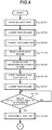
- Fig. 4 is a first flowchart for depicting the flow of the third discharge process in the sheet processing apparatus 3 according to the embodiment.
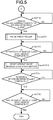
- Fig. 5 is a second flowchart for depicting the flow of the third discharge process in the sheet processing apparatus 3 according to the embodiment.
- Fig. 6 is a side view illustrating a first operation state in the third discharge process of the sheet processing apparatus 3 according to the embodiment.
- Fig. 7 is a side view illustrating a second operation state in the third discharge process of the sheet processing apparatus 3 according to the embodiment.
- Fig. 8 is a side view illustrating a third operation state in the third discharge process of the sheet processing apparatus 3 according to the embodiment.
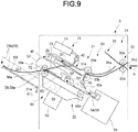
- Fig. 9 is a side view illustrating a fourth operation state in the third discharge process of the sheet processing apparatus 3 according to the embodiment.
- Fig. 10 is a side view illustrating a fifth operation state in the third discharge process of the sheet processing apparatus 3 according to the embodiment.
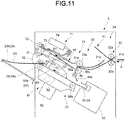
- Fig. 11 is a side view illustrating a sixth operation state in the third discharge process of the sheet processing apparatus 3 according to the embodiment.
- Fig. 12 is a side view illustrating a seventh operation state in the third discharge process of the sheet processing apparatus 3 according to the embodiment.
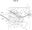
- Fig. 13 is a side view illustrating an eighth operation state in the third discharge process of the sheet processing apparatus 3 according to the embodiment.
- the post-processing controller 25 moves the movable tray 23b to the standby position (ACT 01) .
- the post-processing controller 25 raises the movable tray 23b upwards in the vertical direction to make an altitude difference between the movable tray 23b and the processing tray 51 less than a predetermined difference.
- the standby position of the movable tray 23b is a position below a protrusion position of the thruster 56a in the vertical direction, which does not interfere with the thruster 56a.
- the post-processing controller 25 energizes the solenoid 74 to lower the pinch roller 72 from the standby position to the rotational position (ACT 02) .
- the post-processing controller 25 sandwiches the sheet bundle SS between the pinch roller 72 and the conveyance roller 59.
- the post-processing controller 25 energizes the electromagnetic clutch 63 to connect the bundle claw drive motor 62 in a stopped state with the ejector 56 (ACT 03).
- the post-processing controller 25 starts driving the conveyance roller 59 to convey the sheet bundle SS to the downstream side in the sheet conveyance direction (ACT 04). Along with the start of driving the conveyance roller 59, the post-processing controller 25 starts lowering the movable tray 23b downwards in the vertical direction.
- the post-processing controller 25 waits for a predetermined period of time while continuing to drive the conveyance roller 59 (ACT 05).
- the predetermined period of time is several tens of milliseconds or the like, and is taken to eliminate deflection of the sheet bundle SS.
- the post-processing controller 25 starts driving the bundle claw drive motor 62 (ACT 06). As in the second operation state shown in Fig. 7 , the post-processing controller 25 moves the ejector 56 and the thruster 56a from the reference position towards the downstream side in the sheet conveyance direction. If the ejector 56 contacts with the rear end of the sheet bundle SS in the sheet conveyance direction, the ejector 56 extrudes the sheet bundle SS towards the downstream side in the sheet conveyance direction. The tip of the thruster 56a in the sheet conveyance direction protrudes towards the downstream side in the sheet conveyance direction with respect to the conveyance roller 59. The post-processing controller 25 drives the bundle claw belt 58 to rotate and moves the bundle claw 57 from the home position HP to the downstream side in the sheet conveyance direction on the upper surface side of the processing tray 51.
- the post-processing controller 25 energizes the solenoid 74 to apply a driving force towards the rotational position to the pinch roller 72 (ACT 07) .
- the post-processing controller 25 drives the pinch roller 72 in a descending direction at a timing when the bundle claw 57 receives the sheet bundle SS from the ejector 56.
- the post-processing controller 25 presses the sheet bundle SS towards the conveyance roller 59 and the conveyance surface 51a by the pinch roller 72 driven in the descending direction. This prevents the pinch roller 72 from rising and prevents the sheet bundle SS from bending.
- the post-processing controller 25 determines whether or not an amount of driving by the bundle claw drive motor 62 reaches a first predetermined amount (ACT 08) .
- the amount of driving by the bundle claw drive motor 62 is the number of steps.
- the post-processing controller 25 repeatedly executes the determination process in ACT 08.
- the post-processing controller 25 proceeds to the process in ACT 09.
- the post-processing controller 25 stops energizing the electromagnetic clutch 63 and disconnects the bundle claw drive motor 62 from the ejector 56 (ACT 09) .
- the post-processing controller 25 moves the ejector 56 and the thruster 56a to the reference position by the return force towards the upstream side in the sheet conveyance direction.
- the post-processing controller 25 lowers the movable tray 23b downwards in the vertical direction to a position at least below a movement locus of the thruster 56a.
- the post-processing controller 25 determines whether or not the amount of driving by the bundle claw drive motor 62 reaches a second predetermined amount which is larger than the first predetermined amount (ACT 10).
- the post-processing controller 25 repeatedly executes the determination process in ACT 10.
- the post-processing controller 25 proceeds to the process in ACT 11.
- the post-processing controller 25 energizes the solenoid 74 to raise the pinch roller 72 from the rotational position to the standby position (ACT 11) .
- the post-processing controller 25 avoids interference between the bundle claw 57 moving in the sheet conveyance direction and the pinch roller driving mechanism 71.
- the post-processing controller 25 determines whether or not the amount of driving by the bundle claw drive motor 62 reaches a predetermined target amount of driving and the driving by the bundle claw drive motor 62 is completed (ACT 12).
- the post-processing controller 25 repeatedly executes the determination processing in ACT 12.
- the post-processing controller 25 proceeds to the process in ACT 13. As in the seventh operation state shown in Fig. 12 , the post-processing controller 25 determines that the discharge of the sheet bundle SS from the processing tray 51 to the movable tray 23b is completed, and then proceeds to the process in ACT 13.
- the post-processing controller 25 starts driving the bundle claw drive motor 62 so as to drive the bundle claw belt 58 to rotate in the reverse direction to return the bundle claw 57 to the home position HP (ACT 13).
- the reverse direction is the clockwise direction shown in Fig. 12 .
- the post-processing controller 25 moves the bundle claw 57 towards the upstream side in the sheet conveyance direction at the upper surface side of the processing tray 51.
- the post-processing controller 25 moves the bundle claw 57 along the outer periphery of the second belt roller 58b from the upper surface side of the processing tray 51 to the lower surface side thereof.
- the post-processing controller 25 moves the bundle claw 57 towards the home position HP from the second belt roller 58b at the lower surface side of the processing tray 51.
- the post-processing controller 25 determines whether or not the amount of driving of the conveyance roller 59 reaches a predetermined target amount of driving and the driving of the conveyance roller 59 is completed (ACT 14).
- the post-processing controller 25 repeatedly executes the determination processing in ACT 14.
- the post-processing controller 25 proceeds to the process in ACT 15.
- the post-processing controller 25 determines whether or not the bundle claw 57 reaches the home position HP and the driving by the bundle claw drive motor 62 is completed (ACT 15) . As in the eighth operation state shown in Fig. 13 , the post-processing controller 25 determines whether or not a sensor detects that the bundle claw 57 is present at the home position HP.
- the post-processing controller 25 repeatedly executes the determination processing in ACT 15.
- the post-processing controller 25 terminates the process.
- the sheet processing apparatus 3 of the embodiment described above has the post-processing controller 25 for controlling sheet conveyance by the conveyance roller 59, the pinch roller 72, and the bundle claw 57, the stability of conveyance can be improved.
- the post-processing controller 25 for conveying the sheet by the conveyance roller 59 and the pinch roller 72 prior to sheet conveyance by the bundle claw 57 bending of the sheet S can be prevented.
- the post-processing controller 25 for moving the pinch roller 72 to the standby position prior to sheet conveyance by the bundle claw 57 the interference between the bundle claw 57 and the pinch roller 72 can be prevented.
- the post-processing controller 25 for conveying the sheet with the bundle claw 57 after the sheet is conveyed by the conveyance roller 59 and the pinch roller 72 the sheet S can be accurately conveyed.
- the post-processing controller 25 for applying the force towards the rotational position to the pinch roller 72 when the sheet is conveyed by the conveyance roller 59 and the pinch roller 72 bending of the sheet S caused by the ascent of the pinch roller 72 can be prevented.
- the post-processing controller 25 which applies the force towards the rotational position to the pinch roller 72 the pinch roller 72 can press the sheet S towards the conveyance roller 59, thereby preventing the bending of the sheet.
- the post-processing controller 25 for switching the selection between the roller discharge process and the combined discharge process With the post-processing controller 25 for switching the selection between the roller discharge process and the combined discharge process, bending of the sheet S can be prevented and the stability of discharge of the sheet S can be improved. With the post-processing controller 25 for switching the selection between roller discharge process and combined discharge process according to the number of sheets S, conveyance failure due to an increase in the number of sheets S can be prevented. With the post-processing controller 25 which carries out combined discharge process depending on the number of sheets S, it is possible to accurately convey the sheet S by the bundle claw 57, the conveyance roller 59 and the pinch roller 72. Even if there are a large number of sheets S, the bundle claw 57 can accurately transmit the driving force in the sheet conveyance direction, and the stability of the conveyance can be improved.
- the post-processing controller 25 for switching the selection between the roller discharge process or the combined discharge process and the extrusion discharge process With the post-processing controller 25 for switching the selection between the roller discharge process or the combined discharge process and the extrusion discharge process, bending of the sheet S can be prevented and the stability of discharge of the sheet S can be improved. With the post-processing controller 25 which switches between the roller discharge process or the combined discharge process and the extrusion discharge process depending on the size of the sheet S, it is possible to prevent the sheet S from bending caused by an increase in the sheet size. With the post-processing controller 25 which performs the roller discharge process or the combined discharge process depending on the size of the sheet S, the bending of the sheet S can be prevented by the conveyance roller 59 and the pinch roller 72. With the conveyance roller 59 and the pinch roller 72, the bending of the sheet S can be prevented, and the conveyance failure can also be prevented even if the size of the sheet S is large or the rigidity of the sheet S is low.
- the post-processing controller 25 which drives the conveyance roller 59 to rotate in the sheet conveyance direction prior to sheet conveyance by the bundle claw 57, the bending of the sheet S can be prevented. Even if the sheet S on the processing tray 51 bends, the conveyance roller 59 can reduce a bending amount by being driven to rotate in the sheet conveyance direction.
- the post-processing controller 25 switches the selection between the first discharge process and the second discharge process or the third discharge process depending on the sheet size, but the present invention is not limited thereto.
- the post-processing controller 25 may perform the second discharge process or the third discharge process without performing the first discharge process regardless of the sheet size.
- the post-processing controller 25 may change at least one of the conveyance speed of the conveyance roller 59 and the conveyance speed of the bundle claw 57.
- the post-processing controller 25 may change the conveyance speed of at least one of the conveyance roller 59 and the bundle claw 57 according to the state quantity of the sheet S or the sheet bundle SS.
- all or a part of the functions of the sheet processing apparatus 3 may be realized by hardware.
- the hardware is, for example, a LSI (Large Scale Integration), an ASIC (Application Specific Integrated Circuit), a PLD (Programmable Logic Device), a FPGA (Field Programmable Gate Array), or the like.
- the programs executed by each CPU of the sheet processing apparatus 3 may be recorded on a computer-readable recording medium.
- the recording medium is, for example, a portable medium such as a flexible disk, a magneto-optical disk, a ROM, a CD-ROM, or the like, or a storage device such as a hard disk built in a computer system.
- the programs may be transmitted via an electric communication line.
- the stability of conveyance can be improved.
- the post-processing controller 25 for conveying the sheet by the conveyance roller 59 and the pinch roller 72 prior to sheet conveyance by the bundle claw 57 bending of the sheet S can be prevented.
- the post-processing controller 25 for moving the pinch roller 72 to the standby position prior to sheet conveyance by the bundle claw 57 the interference between the bundle claw 57 and the pinch roller 72 can be prevented.
- the post-processing controller 25 for conveying the sheet with the bundle claw 57 after the sheet is conveyed by the conveyance roller 59 and the pinch roller 72 the sheet S can be accurately conveyed.
Landscapes
- Engineering & Computer Science (AREA)
- Mechanical Engineering (AREA)
- Physics & Mathematics (AREA)
- General Physics & Mathematics (AREA)
- Pile Receivers (AREA)
- Folding Of Thin Sheet-Like Materials, Special Discharging Devices, And Others (AREA)
- Paper Feeding For Electrophotography (AREA)
- Delivering By Means Of Belts And Rollers (AREA)
Abstract
A sheet processing apparatus includes a processing tray (51); a conveyance roller (59) for conveying a sheet towards a downstream side in a sheet conveyance direction; a pinch roller (72) for moving between a first position away from the conveyance roller and a second position close to the conveyance roller, and to sandwich the sheet with the conveyance roller at the second position when the sheet is conveyed by the conveyance roller. The apparatus further includes an extruding member (56, 57) for extruding an upstream end of the sheet from the upstream side towards the downstream side to convey the sheet placed on the processing tray. The apparatus additionally includes a controller for conveying the sheet with the extruding member after the sheet is conveyed by the pinch roller and the conveyance roller when the sheet on the processing tray is conveyed to the downstream side in the sheet conveyance direction.
Description
- This application is based upon and claims the benefit of priority from Japanese Patent Application No.
2017-170374, filed September 5, 2017 - Embodiments described herein relate generally to a sheet processing apparatus.
- A sheet processing apparatus executes a post-processing such as sorting and stapling on a sheet-like image receiving medium (hereinafter, referred to as a "sheet") conveyed from an image forming apparatus. The sheet processing apparatus includes a standby section, a processing section, and a discharge section. The standby section temporarily retains the sheet. The standby section sends the retained sheet to the processing section at a prescribed timing. The processing section executes the post-processing by aligning the sheet received from the standby section. The processing section discharges the sheet subjected to the post-processing to the discharge section.
- For example, when the sheet is discharged to the discharge section, the processing section extrudes an edge of the sheet on an upstream side in a conveyance direction towards a downstream side in the conveyance direction with an extruding member. However, there is a possibility that the sheet extruded by the extruding member bends.
- For example, when the sheet is discharged to the discharge section, the processing section sandwiches the sheet between a pinch roller and a conveyance roller to convey the sheet by the rotation of the pinch roller and the conveyance roller. However, there is a possibility that the pinch roller and the conveying roller could slide against the sheet.
- One of the objects of the present invention is to improve prior art techniques and overcome at least some of the prior art problems as for instance above illustrated.
- According to a first aspect of the present invention, it is provided a sheet processing apparatus, comprising:
- a processing tray configured to stack a sheet;
- a conveyance roller, arranged on a downstream side in a sheet conveyance direction with respect to the processing tray, configured to convey the sheet towards the downstream side in the sheet conveyance direction;
- a pinch roller configured to move between a first position distal from the conveyance roller and a second position proximate to the conveyance roller, and to sandwich the sheet with the conveyance roller at the second position when the sheet is conveyed by the conveyance roller;
- an extruder configured to extrude an end of an upstream sheet in the sheet conveyance direction from an upstream side towards the downstream side in the sheet conveyance direction to convey the sheet placed on the processing tray; and
- a controller configured to control the conveyance roller, the pinch roller and the extruder to move the pinch roller to the second position when the sheet placed on the processing tray is conveyed to the downstream side in the sheet conveyance direction, move the pinch roller to the first position from the second position after the sheet is conveyed by the pinch roller and the conveyance roller, and then convey the sheet with the extruder.
- Optionally, in the sheet processing apparatus according to the first aspect, the controller is configured to apply a force towards the second position to the pinch roller when the sheet is conveyed by the pinch roller and the conveyance roller.
- Optionally, in the sheet processing apparatus according to the first aspect, the controller is configured to switch a selection between a roller discharge process for conveying the sheet only with the pinch roller and the conveyance roller and a combined discharge process for conveying the sheet with the pinch roller, the conveyance roller and the extruder, and the controller is configured to switch the selection based on whether a number of sheets is less than a predetermined value.
- Optionally, in the sheet processing apparatus according to the first aspect, the controller is configured to switch a selection between a roller discharge process for conveying the sheet only with the pinch roller and the conveyance roller and a combined discharge process for conveying the sheet with the pinch roller, the conveyance roller and the extruder, and the controller is configured to switch the selection based on whether a number of sheets is less than a predetermined value.
- Optionally, in the sheet processing apparatus according to the first aspect, the controller is configured to switch a selection between the roller discharge process or the combined discharge process and an extrusion discharge process for conveying the sheet only by the extruder, based on whether a sheet size is less than a threshold value (it is noted that the switching between the roller discharge process and the combined discharge process can be made based on whether a number of sheets is less than a predetermined value and/or whether a sheet size is less than a threshold value).
- Optionally, in the sheet processing apparatus according to the first aspect, the controller is configured to drive the conveyance roller to rotate in the sheet conveyance direction prior to conveyance of the sheet by the extruder.
- Optionally, in the sheet processing apparatus according to the first aspect, the controller is configured to drive the conveyance roller to rotate in the sheet conveyance direction prior to conveyance of the sheet by the extruder.
- Optionally, in the sheet processing apparatus according to the first aspect, the conveyance roller is configured to convey the sheet in the conveyance direction along a conveyance path, wherein the conveyance path includes a first conveyance path, a second conveyance path, and a third conveyance path, the first and second conveyance paths being bifurcated from the first conveyance path.
- Optionally, in the sheet processing apparatus according to the first aspect, the first conveyance path is arranged to guide the sheet to a standby section, the second conveyance path is configured to guide the sheet to a discharger, and the third conveyance path is arranged to guide the sheet to the processing tray.
- Optionally, in the sheet processing apparatus according to the first aspect, the first position is a standby position and the second position is a rotational position.
- According to a second aspect of the invention, it is provided a sheet processing method, comprising:
- arranging a conveyance roller on a downstream side in a sheet conveyance direction with respect to a processing tray in which a sheet is stacked,
- causing the conveyance roller to convey the sheet towards the downstream side in the sheet conveyance direction;
- providing a pinch roller to move between a first position distal from the conveyance roller and a second position proximate to the conveyance roller, and to sandwich the sheet with the conveyance roller at the second position when the sheet is conveyed by the conveyance roller;
- causing an extruder to extrude an end of an upstream sheet in the sheet conveyance direction from an upstream side towards the downstream side in the sheet conveyance direction to convey the sheet placed on the processing tray; and
- controlling, by a controller, the conveyance roller, the pinch roller and the extruder to move the pinch roller to the second position when the sheet placed on the processing tray is conveyed to the downstream side in the sheet conveyance direction, move the pinch roller to the first position from the second position after the sheet is conveyed by the pinch roller and the conveyance roller, and then convey the sheet with the extruder.
- Optionally, the sheet processing method according to the second aspect of the invention further comprises applying a force towards the second position to the pinch roller when the sheet is conveyed by the pinch roller and the conveyance roller.
- Optionally, the sheet processing method according to the second aspect further comprises switching a selection between a roller discharge process for conveying the sheet only with the pinch roller and the conveyance roller and a combined discharge process for conveying the sheet with the pinch roller, the conveyance roller and the extruder, wherein the switching is performed based on whether a number of sheets is less than a predetermined value.
- Optionally, the sheet processing method according to the second aspect further comprises switching a selection between a roller discharge process for conveying the sheet only with the pinch roller and the conveyance roller and a combined discharge process for conveying the sheet with the pinch roller, the conveyance roller and the extruder, wherein the switching is performed based on whether a number of sheets is less than a predetermined value.
- Optionally, the sheet processing method according to the second aspect further comprises switching a selection between the roller discharge process or the combined discharge process and an extrusion discharge process for conveying the sheet only by the extruder, based on whether a sheet size is less than a threshold value (it is noted that the switching between the roller discharge process and the combined discharge process can be made based on whether a number of sheets is less than a predetermined value and/or whether a sheet size is less than a threshold value).
- Optionally, the sheet processing method according to the second aspect further comprises driving the conveyance roller to rotate in the sheet conveyance direction prior to conveyance of the sheet by the extruder.
- Optionally, the sheet processing method according to the second aspect further comprises driving the conveyance roller to rotate in the sheet conveyance direction prior to conveyance of the sheet by the extruder.
- Optionally, the sheet processing method according to the second aspect further comprises conveying, by the conveyance roller, the sheet in the conveyance direction along a conveyance path, wherein the conveyance path includes a first conveyance path, a second conveyance path, and a third conveyance path, the first and second conveyance paths being bifurcated from the first conveyance path.
-
-
Fig. 1 is a diagram schematically exemplifying the overall configuration of an image forming system according to at least one embodiment; -
Fig. 2 is a block diagram exemplifying functional components of an image forming apparatus and a sheet processing apparatus according to at least one embodiment; -
Fig. 3 is a side view schematically exemplifying the configuration of a sheet processing apparatus according to at least one embodiment; -
Fig. 4 is a first flowchart for depicting a flow of a third discharge process in the sheet processing apparatus according to at least one embodiment; -
Fig. 5 is a second flowchart for depicting the flow of the third discharge process in the sheet processing apparatus according to at least one embodiment; -
Fig. 6 is a side view illustrating a first operation state in the third discharge process of the sheet processing apparatus according to at least one embodiment; -
Fig. 7 is a side view illustrating a second operation state in the third discharge process of the sheet processing apparatus according to at least one embodiment; -
Fig. 8 is a side view illustrating a third operation state in the third discharge process of the sheet processing apparatus according to at least one embodiment; -
Fig. 9 is a side view illustrating a fourth operation state in the third discharge process of the sheet processing apparatus according to at least one embodiment; -
Fig. 10 is a side view illustrating a fifth operation state in the third discharge process of the sheet processing apparatus according to at least one embodiment; -
Fig. 11 is a side view illustrating a sixth operation state in the third discharge process of the sheet processing apparatus according to at least one embodiment; -
Fig. 12 is a side view illustrating a seventh operation state in the third discharge process of the sheet processing apparatus according to at least one embodiment; and -
Fig. 13 is a side view illustrating an eighth operation state in the third discharge process of the sheet processing apparatus according to at least one embodiment. - In accordance with at least one embodiment, a sheet processing apparatus comprises a processing tray; a conveyance roller, arranged on a downstream side in a sheet conveyance direction with respect to the processing tray, configured to convey a sheet towards the downstream side in the sheet conveyance direction; a pinch roller configured to move between a standby position (an example of a first position) away (e.g. distal) from the conveyance roller and a rotational position (an example of a second position) close (or proximate) to the conveyance roller, and to sandwich the sheet with the conveyance roller at the rotational position when the sheet is conveyed by the conveyance roller; an extruding member configured to extrude an upstream end of the sheet in the sheet conveyance direction from the upstream side towards the downstream side in the sheet conveyance direction to convey the sheet placed on the processing tray; and a controller configured to control the conveyance roller, the pinch roller and the extruding member in such a manner as to move the pinch roller to the rotational position if the sheet placed on the processing tray is conveyed to the downstream side in the sheet conveyance direction, move the pinch roller to the standby position after the sheet is conveyed by the pinch roller and the conveyance roller, and then convey the sheet with the extruding member.
- Hereinafter, a sheet processing apparatus according to an embodiment is described with reference to the accompanying drawings.
- In the following figures, the same component is denoted with the same reference numeral.
-
Fig. 1 is a diagram schematically exemplifying the overall configuration of animage forming system 1 according to the embodiment.Fig. 2 is a block diagram exemplifying the functional components of animage forming apparatus 2 and asheet processing apparatus 3 according to the embodiment. - The
image forming system 1 is provided with theimage forming apparatus 2 and thesheet processing apparatus 3. Theimage forming apparatus 2 forms an image on a sheet-like medium (hereinafter, collectively referred to as a "sheet S") such as a paper. Thesheet processing apparatus 3 executes a post-processing on the sheet S discharged from theimage forming apparatus 2. - The
image forming apparatus 2 includes acontrol panel 11, a scanner section (a scanner) 12, a printer section (a printer) 13, a sheet feed section (a feeder) 14, a sheet discharge section (a discharger) 15 and animage forming controller 16. - The
control panel 11 includes an operation section, a display section and a panel controller. The operation section receives an operation by a user. For example, the operation section includes various keys and a touch panel. The display section displays various information. The panel controller controls reception of an operation by the user on the operation section and display on the display section. The panel controller includes a control circuit having a CPU (Central Processing Unit), a ROM (Read Only Memory), and a RAM (Random Access Memory) . The control circuit may carry out operations according to program-executable instructions stored in a non-transitory memory. - For example, the
control panel 11 receives an input relating to the sheet S such as a size (sheet size) of the sheet S and the type of the sheet S. The sheet size includes a regular size and an irregular size. The type of the sheet S includes a paper quality, a quantity, a thickness, and the like. - For example, the
control panel 11 receives an input relating to the type of the post-processing carried out on the sheet S. Thecontrol panel 11 receives a selection of any one of a plurality of different processing modes. The plurality of different processing modes includes a sorting mode, a stapling mode and a non-sorting mode. The sorting mode refers to a processing mode in which a sorting process is executed. The stapling mode refers to a processing mode in which a binding process (stapling process) by a staple is executed. The non-sorting mode refers to a processing mode in which the execution of the sorting process and the stapling process is prohibited. For example, in a case of receiving the selection of the stapling mode, thecontrol panel 11 receives an input relating to the number of sheets S (the number of stapled sheets) forming a sheet bundle SS. - For example, at the time of receiving selection of the non-sorting mode, the
control panel 11 receives selection of any one of a plurality of discharge destinations for the sheet S. The plurality of discharge destinations includes a fixedtray 23a and amovable tray 23b described later. - The
image forming apparatus 2 sends the information relating to the sheet S and the information relating to the type of the post-processing received by thecontrol panel 11 to thesheet processing apparatus 3. - The
scanner section 12 includes a reading section and a scanner controller. The reading section reads image information which is a copy object as intensity of light. The scanner controller controls reading of the image information by the reading section. The scanner controller includes a control circuit having a CPU, a ROM, and a RAM. Thescanner section 12 sends the read image information to theprinter section 13. - The
printer section 13 forms an output image (hereinafter, referred to as a "toner image") with a developer such as a toner based on the image information received from thescanner section 12 or an external device. Theprinter section 13 transfers the toner image onto the surface of the sheet S. Theprinter section 13 applies heat and pressure to the toner image on the surface of the sheet S to fix the toner image on the sheet S. Theprinter section 13 sends the sheet S on which the toner image is fixed to thesheet discharge section 15. Theprinter section 13 includes a printer controller. The printer controller includes a control circuit having a CPU, a ROM, and a RAM. The printer controller controls the printing of the image on the sheet S by theprinter section 13. - The
sheet feed section 14 supplies the sheets S one by one to theprinter section 13 in accordance with a timing at which theprinter section 13 forms the toner image. For example, thesheet feed section 14 includes a plurality of the sheet feed cassettes. Each of the sheet feed cassettes accommodates a sheet S of a predetermined size and type in advance. Each of the sheet feed cassettes has a pickup roller. Each pickup roller picks up the sheets S one by one from each of the sheet feed cassettes . Each pickup roller sends the sheet S taken out from each of the sheet feed cassettes to theprinter section 13. - The
sheet discharge section 15 conveys the sheet S received from theprinter section 13 to thesheet processing apparatus 3. - The
image forming controller 16 controls the whole operations of theimage forming apparatus 2. Theimage forming controller 16 controls thecontrol panel 11, thescanner section 12, theprinter section 13, thesheet feed section 14 and thesheet discharge section 15. Theimage forming controller 16 includes, for example, a CPU, a ROM and a RAM. - The
sheet processing apparatus 3 is arranged adjacently to theimage forming apparatus 2. Thesheet processing apparatus 3 executes the post-processing designated via thecontrol panel 11 on the sheet S conveyed from theimage forming apparatus 2. For example, the post-processing is the sorting process, the stapling process, or the like. - The
sheet processing apparatus 3 includes astandby section 21, aprocessing section 22, adischarge section 23, aconveyance section 24, apost-processing controller 25, a bundleclaw driving mechanism 61, and a pinchroller driving mechanism 71. - The
standby section 21 temporarily retains the sheet S received from theimage forming apparatus 2. For example, a plurality of succeeding sheets S stands by on thestandby section 21 while the post-processing is executed on the former sheet S by theprocessing section 22. Thestandby section 21 is arranged above theprocessing section 22 in a vertical direction. A plurality of sheets S overlaps in a thickness direction and stands by on thestandby section 21. If theprocessing section 22 is in a state capable of receiving the sheet S, thestandby section 21 drops the sheet S that is being retained towards theprocessing section 22. - The
processing section 22 carries out the post-processing on the sheet S received from thestandby section 21. For example, theprocessing section 22 carries out the sorting process for gathering a plurality of sheets S and then aligning them. For example, theprocessing section 22 carries out the binding process (stapling process) with a staple on the sheet bundle SS formed by gathering a plurality of sheets S. Theprocessing section 22 discharges the sheet S on which the post-processing is carried out to thedischarge section 23. - The
discharge section 23 supports the sheet S received from thestandby section 21 and theprocessing section 22. Thedischarge section 23 includes the fixedtray 23a and themovable tray 23b. For example, the fixedtray 23a is arranged at the upper part of thesheet processing apparatus 3. For example, themovable tray 23b is arranged on the side of thesheet processing apparatus 3. Themovable tray 23b moves in an upper and lower direction along the side of thesheet processing apparatus 3. For example, the upper and lower direction is the vertical direction. The fixedtray 23a and themovable tray 23b support the sheet S received from thestandby section 21 and theprocessing section 22. - The
conveyance section 24 includes aconveyance path 31, aninlet roller mechanism 32, and anoutlet roller mechanism 33. - The
conveyance path 31 is provided inside thesheet processing apparatus 3. Theconveyance path 31 guides the sheet S received from theimage forming apparatus 2 to thestandby section 21, theprocessing section 22, or thedischarge section 23. Theconveyance path 31 includes afirst conveyance path 31a, asecond conveyance path 31b and athird conveyance path 31c which bifurcate from thefirst conveyance path 31a. Thefirst conveyance path 31a guides the sheet S to thestandby section 21. Thesecond conveyance path 31b guides the sheet S to the fixedtray 23a of thedischarge section 23. Thethird conveyance path 31c guides the sheet S to theprocessing section 22. - The
inlet roller mechanism 32 is arranged between the upstream end of theconveyance path 31 in the sheet conveyance direction and thesheet discharge section 15 of theimage forming apparatus 2. Theinlet roller mechanism 32 sends the sheet S received from theimage forming apparatus 2 to theconveyance path 31. - The
outlet roller mechanism 33 is arranged between the downstream end of thefirst conveyance path 31a in the sheet conveyance direction and thestandby section 21. Theoutlet roller mechanism 33 sends the sheet S received from thefirst conveyance path 31a to thestandby section 21. - The
post-processing controller 25 controls the whole operations of thesheet processing apparatus 3. Thepost-processing controller 25 controls thestandby section 21, theprocessing section 22, thedischarge section 23, theconveyance section 24, the bundleclaw driving mechanism 61, and the pinchroller driving mechanism 71. Thepost-processing controller 25 includes a control circuit having a CPU, a ROM, and a RAM. - Details of the structure of the
sheet processing apparatus 3 are described below. -
Fig. 3 is a side view schematically exemplifying the configuration of thesheet processing apparatus 3 according to the embodiment. - The
conveyance section 24 includes theconveyance path 31 where asheet supply port 31d and asheet discharge port 31e are formed. Thesheet supply port 31d is formed to face thesheet discharge section 15 of theimage forming apparatus 2 at the upstream end of theconveyance path 31 in the sheet conveyance direction. The sheet S discharged from theimage forming apparatus 2 is sent to theconveyance path 31 through thesheet supply port 31d. Thesheet discharge port 31e is formed to face thestandby section 21 at the downstream end of thefirst conveyance path 31a in the sheet conveyance direction. The sheet S passing through thefirst conveyance path 31a is sent to thestandby section 21 through thesheet discharge port 31e. - The
first conveyance path 31a guides the sheet S to thestandby section 21 through thesheet supply port 31d if the sorting mode or the stapling mode is selected. - The
second conveyance path 31b guides the sheet S to the fixedtray 23a if the fixedtray 23a of thedischarge section 23 is selected as the discharge destination of the sheet S in the non-sorting mode. - The
third conveyance path 31c guides the sheet S directly to theprocessing section 22 if themovable tray 23b of thedischarge section 23 is selected as the discharge destination of the sheet S in the non-sorting mode. Thethird conveyance path 31c may enable the sheet S to pass through thestandby section 21 without retaining the sheet S in thestandby section 21, when guiding the sheet S directly to theprocessing section 22. - The
inlet roller mechanism 32 of theconveyance section 24 includes afirst inlet roller 32a and asecond inlet roller 32b. Thefirst inlet roller 32a and thesecond inlet roller 32b are opposed to each other in a radial direction thereof with rotation axes parallel to each other. Thefirst inlet roller 32a is a driven roller disposed on the upper surface side of theconveyance path 31. Thesecond inlet roller 32b is a driving roller arranged on the lower surface side of theconveyance path 31. Thefirst inlet roller 32a is driven to rotate by a rotational driving force transmitted from thesecond inlet roller 32b directly or via the sheet S. Thefirst inlet roller 32a and thesecond inlet roller 32b sandwich the sheet S from both sides in the thickness direction of the sheet S at a nip therebetween. Thefirst inlet roller 32a and thesecond inlet roller 32b convey the sheet S that is sandwiched at the nip to the downstream side in the sheet conveyance direction. - The
outlet roller mechanism 33 of theconveyance section 24 comprises afirst outlet roller 33a and asecond outlet roller 33b. Thefirst outlet roller 33a and thesecond outlet roller 33b are opposed to each other in the radial direction thereof with rotation axes parallel to each other. Thefirst outlet roller 33a is a driven roller disposed on the upper surface side of thefirst conveyance path 31a. Thesecond outlet roller 33b is a driving roller disposed on the lower surface side of thefirst conveyance path 31a. Thefirst outlet roller 33a is driven to rotate by a rotational driving force transmitted from thesecond outlet roller 33b directly or via the sheet S. Thefirst outlet roller 33a and thesecond outlet roller 33b sandwich the sheet S from both sides in the thickness direction of the sheet S at a nip therebetween. Thefirst outlet roller 33a and thesecond outlet roller 33b convey the sheet S that is sandwiched at the nip to the downstream side in the sheet conveyance direction. - The
standby section 21 includes astandby tray 41, anassist guide 43, and apaddle section 45. The sheet conveyance direction in thestandby section 21 is indicated by a first arrow D1 shown inFig. 3 . The direction indicated by the first arrow D1 is an approach direction of the sheet S from thefirst outlet roller 33a and thesecond outlet roller 33b to thestandby tray 41. - The upstream end in the sheet conveyance direction of the
standby tray 41 is arranged adjacently to thefirst outlet roller 33a and thesecond outlet roller 33b. The upstream end of thestandby tray 41 is arranged below thesheet discharge port 31e of theconveyance path 31 in the vertical direction. Thestandby tray 41 is tilted with respect to the horizontal direction in such a manner that the downstream side gradually rises vertically upwards with respect to the upstream side as it proceeds from the upstream side to the downstream side in the sheet conveyance direction. A plurality of sheets S is stacked in the thickness direction on thestandby tray 41 and stands by while theprocessing section 22 performs the post-processing on the former sheet S. - The
standby tray 41 includes a pair of tray members moving in mutually opposite directions in a sheet width direction. The sheet width direction is parallel to a plane of the sheet S and perpendicular to the sheet conveyance direction. The pair of the tray members moves towards each other to support the sheet S if the sheet S stands by on thestandby tray 41. In a case of moving the sheet S from thestandby tray 41 to theprocessing section 22, the pair of the tray members moves away from each other to release the support of the sheet S. The pair of the tray members drops the sheet S towards theprocessing section 22 by moving away from each other and then releasing the support of the sheet S. - The
assist guide 43 is arranged above thestandby tray 41 in the vertical direction. For example, the length of theassist guide 43 in the sheet conveyance direction is the same as that of thestandby tray 41 in the sheet conveyance direction. Theassist guide 43 presses the sheet S towards theprocessing section 22 in a case of moving the sheet S from thestandby tray 41 to theprocessing section 22. Theassist guide 43 has a swing shaft parallel to the sheet width direction at the downstream end of the sheet conveyance direction. The upstream end of theassist guide 43 in the sheet conveyance direction is swung around the swing shaft. The upstream end of theassist guide 43 in the sheet conveyance direction is swung downwards to abut against the sheet S in a case of pressing the sheet S towards theprocessing section 22. - The
paddle section 45 is arranged between the upstream end of thestandby tray 41 and theprocessing section 22. Thepaddle section 45 includes a rotation axis parallel to the sheet width direction and apaddle 45a rotating around the rotation axis. For example, thepaddle 45a is made of an elastic material such as rubber. Thepaddle section 45a rotates around the rotation axis while contacting with the sheet S when the sheet S is moved from thestandby tray 41 to theprocessing section 22. For example, thepaddle section 45a rotates in a counterclockwise direction shown inFig. 3 . Thepaddle 45a moves the sheet S falling down to theprocessing section 22 from thestandby tray 41 towards the upstream end of theprocessing section 22 in the sheet conveyance direction. Thepaddle 45a enables the sheet S to contact with the upstream end of theprocessing section 22 in the sheet conveyance direction to align the position of the rear end of the sheet S in the sheet conveyance direction. Thepaddle 45a aligns the position of the sheet S in the sheet conveyance direction in the processing section 22 (that is, thepaddle 45a causes the position of the sheet S to be in a longitudinal alignment). - The
paddle section 45, together with a conveyance roller 59 and a rear end stopper 54 of theprocessing section 22 described later, constitutes a longitudinal alignment device which performs the longitudinal alignment of the sheet S in the sheet conveyance direction. - The
processing section 22 includes aprocessing tray 51, a pair ofhorizontal alignment plates 52, the rear end stopper 54, astapler 55, an ejector 56, athruster 56a, abundle claw 57, abundle claw belt 58, and the conveyance roller 59. The sheet conveyance direction in theprocessing section 22 is indicated by a second arrow D2 shown inFig. 3 . The direction of the second arrow D2 is a discharge direction of the sheet S from theprocessing tray 51. - The
processing tray 51 is arranged below thestandby tray 41 in the vertical direction. Theprocessing tray 51 is tilted with respect to a horizontal direction in such a manner that the downstream side thereof gradually rises upwards in the vertical direction with respect to the upstream side thereof as it goes from the upstream side to the downstream side in the sheet conveyance direction. For example, theprocessing tray 51 is arranged in parallel with thestandby tray 41. Theprocessing tray 51 includes aconveyance surface 51a on which the sheet S is placed. Theconveyance surface 51a supports the sheet S. - The pair of the
horizontal alignment plates 52 is arranged away from each other in the sheet width direction at theconveyance surface 51a of theprocessing tray 51. The pair of thehorizontal alignment plates 52 moves in mutually opposite directions in the sheet width direction. The pair of thehorizontal alignment plates 52 aligns the positions of both ends in the sheet width direction of the sheet S by moving towards each other and sandwiching the sheet S from both sides in the sheet width direction. The pair of thehorizontal alignment plates 52 aligns the position of the sheet S in the sheet width direction (i.e., in a horizontal alignment). The pair of thehorizontal alignment plates 52 moves away from each other at the time of releasing the clamping of the sheet S. - The rear end stopper 54 is arranged at the end in the sheet conveyance direction of the
processing tray 51. For example, the shape of the rear end stopper 54 is a hook shape. The rear end stopper 54 supports the rear end in the sheet conveyance direction of the sheet S placed on theprocessing tray 51. - The
stapler 55 is a binding section which executes the binding process with the staple on the sheet bundle SS formed by aligning a plurality of the sheets S. Thestapler 55 is arranged at the rear side of the upstream end in the sheet conveyance direction of theprocessing tray 51. A plurality of the sheets S is supported by the rear end stopper 54 and the positions of the rear ends thereof are aligned, and then the rear ends of the plurality of the sheets are tightened by thestapler 55 to be fixed. If the stapling mode is selected, thestapler 55 executes the stapling process on the sheet bundle SS, which is supported by the rear end stopper 54 and of which the rear end thereof is aligned. - The ejector 56 is arranged at the upstream end of the
processing tray 51 in the sheet conveyance direction. The ejector 56 is arranged so as to overlap with the rear end stopper 54 if viewed from the sheet width direction at a reference position. For example, the shape of the ejector 56 is a hook shape. The ejector 56 supports the rear end in the sheet conveyance direction of the sheet bundle SS subjected to the stapling process and the sorting process. - The ejector 56 moves to the sheet conveyance direction with respect to the
processing tray 51. For example, the ejector 56 moves from the reference position towards the downstream side in the sheet conveyance direction by a driving force transmitted from a driving source. For example, if the ejector 56 is disconnected from the driving source, the ejector 56 moves to the reference position by a returning force towards the upstream side in the sheet conveyance direction applied by an elastic member. - The ejector 56 moves from the upstream side to the downstream side in the sheet conveyance direction while supporting the sheet bundle SS and moves the sheet bundle SS towards the downstream side in the sheet conveyance direction. The ejector 56 moves the end of the sheet bundle SS to a position where the sheet bundle SS is delivered to the
bundle claw 57. - The
thruster 56a is arranged along theconveyance surface 51a. For example, the shape of thethruster 56a is a plate shape. Thethruster 56a moves in the sheet conveyance direction together with the ejector 56. At the reference position, thethruster 56a is arranged on the upstream side in the sheet conveyance direction with respect to the conveyance roller 59. If moving towards the downstream side in the sheet conveyance direction from the reference position, the tip of thethruster 56a in the sheet conveyance direction projects towards the downstream side in the sheet conveyance direction with respect to the conveyance roller 59. Thethruster 56a protrudes towards the downstream side in the sheet conveyance direction with respect to the conveyance roller 59 so as to extend theconveyance surface 51a towards the downstream side in the sheet conveyance direction. Thethruster 56a contacts with the lower surface of the sheet S protruding towards the downstream side in the sheet conveyance direction with respect to the conveyance roller 59 to support the sheet S. - The
bundle claw 57 is an extruding member (extruder) that extrudes the sheet bundle SS on theprocessing tray 51 towards the downstream side in the sheet conveyance direction to move the sheet bundle SS. Thebundle claw 57 is fixed to thebundle claw belt 58. The shape of thebundle claw 57 may be hook shape, for example. Thebundle claw belt 58 is wound around a pair of a first belt roller 58a and asecond belt roller 58b which are arranged apart from each other in the sheet conveyance direction of theprocessing tray 51. The first belt roller 58a is arranged at the downstream side in the sheet conveyance direction with respect to thesecond belt roller 58b. The first belt roller 58a is a driving roller and rotationally drives thebundle claw belt 58. Thesecond belt roller 58b is a driven roller and is driven to rotate by a rotational driving force transmitted from the first belt roller 58a via thebundle claw belt 58. - The
bundle claw 57 moves as thebundle claw belt 58 rotates. Thebundle claw 57 contacts with the rear end in the sheet conveyance direction of the sheet bundle SS placed on theprocessing tray 51 and conveys the sheet bundle SS in such a manner that it extrudes the sheet bundle SS towards the downstream side in the sheet conveyance direction. Thebundle claw 57 stands by at a position in front of the second belt roller 56b in an opposite direction to the sheet conveyance direction as a home position HP at the lower surface side of theprocessing tray 51. Whether thebundle claw 57 is present at the home position HP is detected by a sensor. - For example, the
bundle claw 57 moves from the home position HP towards thesecond belt roller 58b at the lower surface side of theprocessing tray 51 as thebundle claw belt 58 rotates in a forward direction. The forward rotation of thebundle claw belt 58 is a counterclockwise rotation as shown inFig. 3 . Thebundle claw 57 moves along the outer periphery of thesecond belt roller 58b from the lower surface side to the upper surface side of theprocessing tray 51. The upper surface side of theprocessing tray 51 is theconveyance surface 51a side. At the upper surface side of theprocessing tray 51, thebundle claw 57 receives the sheet bundle SS from the ejector 56 and moves towards the downstream side in the sheet conveyance direction. Thebundle claw 57 moves along the outer periphery of the first belt roller 58a towards the lower surface side of theprocessing tray 51 while conveying the sheet bundle SS. Thebundle claw 57 extrudes the sheet bundle SS towards the downstream side to discharge the sheet bundle SS. - For example, the
bundle claw 57 moves towards the upstream side in the sheet conveyance direction at the upper surface side of theprocessing tray 51 as thebundle claw belt 58 rotates reversely after the discharge of the sheet bundle SS. Thebundle claw 57 moves along the outer periphery of thesecond belt roller 58b from the upper surface side to the lower surface side of theprocessing tray 51 to return to the home position HP. - The
bundle claw belt 58, the first belt roller 58a and thesecond belt roller 58b constitute the bundleclaw driving mechanism 61 for driving thebundle claw 57. - The bundle
claw driving mechanism 61 is provided with a bundleclaw drive motor 62. For example, the bundleclaw drive motor 62 is a driving source for the first belt roller 58a, the ejector 56, and thethruster 56a. The bundleclaw drive motor 62 is always connected to the first belt roller 58a. The bundleclaw drive motor 62 is connected to the ejector 56 and thethruster 56a via anelectromagnetic clutch 63. - The electromagnetic clutch 63 transmits the driving force of the bundle
claw drive motor 62 to the ejector 56 and thethruster 56a at the time of ON (connection) . The electromagnetic clutch 63 interrupts the transmission of the driving force of the bundleclaw drive motor 62 to the ejector 56 and thethruster 56a at the time of OFF (disconnection) . For example, the bundleclaw drive motor 62 rotates thebundle claw belt 58 counterclockwise or clockwise as shown inFig. 3 when theelectromagnetic clutch 63 is turned on. The bundleclaw drive motor 62 moves the ejector 56 and thethruster 56a towards the downstream side in the sheet conveyance direction from the reference position when thebundle claw belt 58 is driven to rotate counterclockwise. - The conveyance roller 59 is arranged so as to overlap with the first belt roller 58a if viewed from the sheet width direction. The conveyance roller 59 aligns the position of the rear end in the sheet conveyance direction of the sheet S placed on the
processing tray 51. The conveyance roller 59 functions as a longitudinal alignment roller for aligning the position of the sheet S in the sheet conveyance direction. The conveyance roller 59, thepaddle section 45 and the rear end stopper 54 constitute a longitudinal aligning device for longitudinally aligning the sheet S. For example, the conveyance roller 59 rotates clockwise as shown inFig. 3 to convey the sheet S placed on theprocessing tray 51 towards the rear end stopper 54. The conveyance roller 59 cooperates with thepaddle section 45 to perform the longitudinal alignment on the sheet S by enabling the rear end of the sheet S to abut against the rear end stopper 54. - The conveyance roller 59 conveys the sheet S placed on the
processing tray 51 towards themovable tray 23b of thedischarge section 23. For example, the conveyance roller 59 rotates counterclockwise as shown inFig. 3 to convey the sheet S towards the downstream side in the sheet conveyance direction. The conveyance roller 59 applies a driving force to the sheet S placed on theprocessing tray 51 by contacting with the sheet S at the lower surface side of the sheet S. The conveyance roller 59 sandwiches the sheet S at a nip between the conveyance roller 59 and apinch roller 72 which is moved to a rotational position by the pinchroller driving mechanism 71 to apply the driving force to the sheet S. - The pinch
roller driving mechanism 71 includes asupport arm 73 that supports thepinch roller 72 and asolenoid 74 that drives thesupport arm 73. - The
pinch roller 72 is a driven roller having no driving source. Thepinch roller 72 moves between a standby position above thestandby tray 41 in the vertical direction and a rotational position close to the conveyance roller 59 below the standby position in the vertical direction. Thepinch roller 72 at the rotational position and the conveyance roller 59 are opposed to each other in a radial direction with their rotation axes parallel to each other. Thepinch roller 72 at the rotational position sandwiches the sheet S with the conveyance roller 59 and is driven to rotate by the rotational driving force of the conveyance roller 59 transmitted via the sheet S. - The
support arm 73 supports thepinch roller 72 at the tip thereof. Thesupport arm 73 has a swing shaft parallel to the sheet width direction at a base end thereof. Thesupport arm 73 rotates around the swing shaft and swings thepinch roller 72 between the standby position and the rotational position. - The
solenoid 74 is connected to the base end of thesupport arm 73. For example, thesolenoid 74 is a latching type solenoid. If a plunger protrudes, thesolenoid 74 swings thepinch roller 72 upwards via thesupport arm 73. Thesolenoid 74 moves thepinch roller 72 to the standby position away from the conveyance roller 59 as the plunger protrudes. If the plunger sinks, thesolenoid 74 swings thepinch roller 72 downwards via thesupport arm 73. Thesolenoid 74 moves thepinch roller 72 to the rotational position close to the conveyance roller 59 as the plunger sinks. - When discharging the sheet S or the sheet bundle SS from the
processing tray 51 to themovable tray 23b, thepost-processing controller 25 switches the process according to a state quantity of the sheet S or the sheet bundle SS. For example, the state quantity of the sheet S or the sheet bundle SS refers to the size (sheet size) of the sheet S, the number of sheets (number of stapled sheets) of the sheet bundle SS, the type of the sheet S, and the like. - For example, as shown in the following Table 1, the
post-processing controller 25 switches the discharge process according to the sheet size and the number of stapled sheets. Thepost-processing controller 25 acquires information relating to the selection of discharge process in response to an operation by the user on thecontrol panel 11.
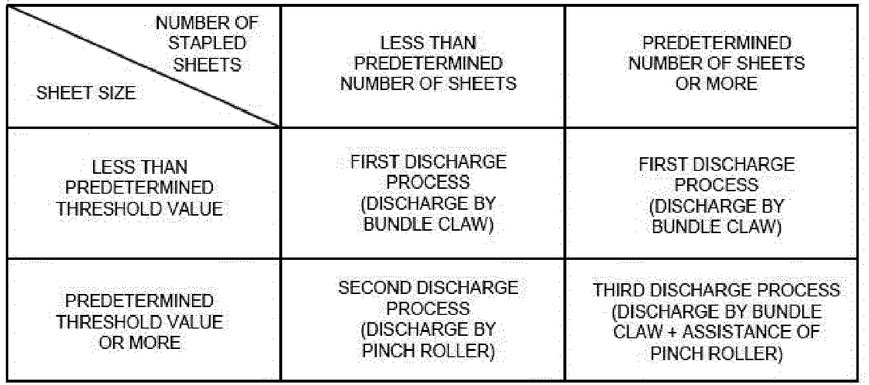
- If the sheet size is smaller than a predetermined threshold value, the
post-processing controller 25 executes a first discharge process. The first discharge process is an extrusion discharge process for conveying the sheet S or the sheet bundle SS only by thebundle claw 57. For example, a size less than the predetermined threshold value includes an A4 size or a letter size in the regular size. In the first discharge process, thepinch roller 72 is stopped at the standby position and the sheet S or the sheet bundle SS is discharged by thebundle claw 57. Thepost-processing controller 25 is connected with the electromagnetic clutch 63 to start driving the bundleclaw drive motor 62 after the longitudinal alignment and the lateral alignment of the sheet S or the binding process of the sheet bundle SS is completed. The bundleclaw drive motor 62 moves the ejector 56 and thethruster 56a from the reference position towards the downstream side in the sheet conveyance direction. The ejector 56 extrudes the sheet S or the sheet bundle SS towards the downstream side in the sheet conveyance direction. The tip of thethruster 56a in the sheet conveyance direction protrudes towards the downstream side in the sheet conveyance direction with respect to the conveyance roller 59. The bundleclaw drive motor 62 drives thebundle claw belt 58 to rotate and moves thebundle claw 57 from the home position HP towards the downstream side in the sheet conveyance direction at the upper surface side of theprocessing tray 51. Thebundle claw 57 receives the sheet S or the sheet bundle SS from the ejector 56 at the upper surface side of theprocessing tray 51 and extrudes the sheet S or the sheet bundle SS towards themovable tray 23b on the downstream side in the sheet conveyance direction. Thepost-processing controller 25 disconnects theelectromagnetic clutch 63 and returns the ejector 56 and thethruster 56a to the reference positions before the conveyance of the sheet S or the sheet bundle SS is completed. Thepost-processing controller 25 rotationally drives thebundle claw belt 58 in a reverse direction after the conveyance of the sheet S or the sheet bundle SS is completed, and then returns thebundle claw 57 to the home position HP thereof. For example, the reverse direction is the clockwise direction inFig. 3 . - If the sheet size is equal to or larger than the predetermined threshold value and the number of stapled sheets is less than the predetermined threshold value, the
post-processing controller 25 executes a second discharge process. The second discharge process is a roller discharge process for conveying the sheet S or the sheet bundle SS only by the conveyance roller 59 and thepinch roller 72. For example, a size equal to or larger than the predetermined threshold value includes an A3 size, a leisure size, or the like in a regular size. In the second discharge process, thebundle claw 57 is stopped at the home position HP and the sheet S or the sheet bundle SS is discharged by the conveyance roller 59 and thepinch roller 72. Thepost-processing controller 25 moves thepinch roller 72 from the standby position to the rotational position after the longitudinal alignment and the lateral alignment of the sheet S or the binding process of the sheet bundle SS is completed. Thepost-processing controller 25 is connected with the electromagnetic clutch 63 to start conveying the sheet S or the sheet bundle SS. Thepost-processing controller 25 starts driving the bundleclaw drive motor 62 to move the ejector 56 and thethruster 56a from the reference position to the downstream side in the sheet conveyance direction. The ejector 56 extrudes the sheet S or the sheet bundle SS to the downstream side in the sheet conveyance direction. The tip of thethruster 56a in the sheet conveyance direction protrudes towards the downstream side in the sheet conveyance direction with respect to the conveyance roller 59. The conveyance roller 59 and thepinch roller 72, together with the ejector 56, convey the sheet S or the sheet bundle SS to themovable tray 23b on the downstream side in the sheet conveyance direction. Thepost-processing controller 25 is disconnected from theelectromagnetic clutch 63 and returns the ejector 56 and thethruster 56a to the reference position before the conveyance of the sheet S or the sheet bundle SS is completed. - If the sheet size is equal to or larger than the predetermined threshold value and the number of stapled sheets is equal to or larger than the predetermined threshold value, the
post-processing controller 25 executes a third discharge process. The third discharge process is a combined discharge process for discharging the sheet S or the sheet bundle SS by thebundle claw 57, the conveyance roller 59 and thepinch roller 72. In the third discharge process, the conveyance of the sheet S or the sheet bundle SS by thebundle claw 57 is assisted by the conveyance roller 59 and thepinch roller 72. - Hereinafter, with reference to
Fig. 4 ,Fig. 5 ,Fig. 6 ,Fig. 7 ,Fig. 8 ,Fig. 9 ,Fig. 10 ,Fig. 11 ,Fig. 12 , andFig. 13 , the flow of the third discharge process in thesheet processing apparatus 3 of the embodiment is described. -
Fig. 4 is a first flowchart for depicting the flow of the third discharge process in thesheet processing apparatus 3 according to the embodiment.Fig. 5 is a second flowchart for depicting the flow of the third discharge process in thesheet processing apparatus 3 according to the embodiment.Fig. 6 is a side view illustrating a first operation state in the third discharge process of thesheet processing apparatus 3 according to the embodiment.Fig. 7 is a side view illustrating a second operation state in the third discharge process of thesheet processing apparatus 3 according to the embodiment.Fig. 8 is a side view illustrating a third operation state in the third discharge process of thesheet processing apparatus 3 according to the embodiment.Fig. 9 is a side view illustrating a fourth operation state in the third discharge process of thesheet processing apparatus 3 according to the embodiment.Fig. 10 is a side view illustrating a fifth operation state in the third discharge process of thesheet processing apparatus 3 according to the embodiment.Fig. 11 is a side view illustrating a sixth operation state in the third discharge process of thesheet processing apparatus 3 according to the embodiment.Fig. 12 is a side view illustrating a seventh operation state in the third discharge process of thesheet processing apparatus 3 according to the embodiment.Fig. 13 is a side view illustrating an eighth operation state in the third discharge process of thesheet processing apparatus 3 according to the embodiment. - First, the
post-processing controller 25 moves themovable tray 23b to the standby position (ACT 01) . Thepost-processing controller 25 raises themovable tray 23b upwards in the vertical direction to make an altitude difference between themovable tray 23b and theprocessing tray 51 less than a predetermined difference. The standby position of themovable tray 23b is a position below a protrusion position of thethruster 56a in the vertical direction, which does not interfere with thethruster 56a. - Next, the
post-processing controller 25 energizes thesolenoid 74 to lower thepinch roller 72 from the standby position to the rotational position (ACT 02) . As in the first operation state shown inFig. 6 , thepost-processing controller 25 sandwiches the sheet bundle SS between thepinch roller 72 and the conveyance roller 59. - The
post-processing controller 25 energizes the electromagnetic clutch 63 to connect the bundleclaw drive motor 62 in a stopped state with the ejector 56 (ACT 03). - The
post-processing controller 25 starts driving the conveyance roller 59 to convey the sheet bundle SS to the downstream side in the sheet conveyance direction (ACT 04). Along with the start of driving the conveyance roller 59, thepost-processing controller 25 starts lowering themovable tray 23b downwards in the vertical direction. - The
post-processing controller 25 waits for a predetermined period of time while continuing to drive the conveyance roller 59 (ACT 05). For example, the predetermined period of time is several tens of milliseconds or the like, and is taken to eliminate deflection of the sheet bundle SS. - The
post-processing controller 25 starts driving the bundle claw drive motor 62 (ACT 06). As in the second operation state shown inFig. 7 , thepost-processing controller 25 moves the ejector 56 and thethruster 56a from the reference position towards the downstream side in the sheet conveyance direction. If the ejector 56 contacts with the rear end of the sheet bundle SS in the sheet conveyance direction, the ejector 56 extrudes the sheet bundle SS towards the downstream side in the sheet conveyance direction. The tip of thethruster 56a in the sheet conveyance direction protrudes towards the downstream side in the sheet conveyance direction with respect to the conveyance roller 59. Thepost-processing controller 25 drives thebundle claw belt 58 to rotate and moves thebundle claw 57 from the home position HP to the downstream side in the sheet conveyance direction on the upper surface side of theprocessing tray 51. - The
post-processing controller 25 energizes thesolenoid 74 to apply a driving force towards the rotational position to the pinch roller 72 (ACT 07) . As in the third operation state shown inFig. 8 , thepost-processing controller 25 drives thepinch roller 72 in a descending direction at a timing when thebundle claw 57 receives the sheet bundle SS from the ejector 56. Thepost-processing controller 25 presses the sheet bundle SS towards the conveyance roller 59 and theconveyance surface 51a by thepinch roller 72 driven in the descending direction. This prevents thepinch roller 72 from rising and prevents the sheet bundle SS from bending. - The
post-processing controller 25 determines whether or not an amount of driving by the bundleclaw drive motor 62 reaches a first predetermined amount (ACT 08) . For example, the amount of driving by the bundleclaw drive motor 62 is the number of steps. - If the determination result is "No" (No in ACT 08), the
post-processing controller 25 repeatedly executes the determination process in ACT 08. - On the other hand, if the determination result is "Yes" (Yes in ACT 08), the
post-processing controller 25 proceeds to the process in ACT 09. - The
post-processing controller 25 stops energizing theelectromagnetic clutch 63 and disconnects the bundleclaw drive motor 62 from the ejector 56 (ACT 09) . As in the fourth operation state shown inFig. 9 , thepost-processing controller 25 moves the ejector 56 and thethruster 56a to the reference position by the return force towards the upstream side in the sheet conveyance direction. Thepost-processing controller 25 lowers themovable tray 23b downwards in the vertical direction to a position at least below a movement locus of thethruster 56a. - The
post-processing controller 25 determines whether or not the amount of driving by the bundleclaw drive motor 62 reaches a second predetermined amount which is larger than the first predetermined amount (ACT 10). - If the result of the determination is "No" (No in ACT 10), the
post-processing controller 25 repeatedly executes the determination process in ACT 10. - On the other hand, if the determination result is "Yes" (Yes in ACT 10), the
post-processing controller 25 proceeds to the process inACT 11. - The
post-processing controller 25 energizes thesolenoid 74 to raise thepinch roller 72 from the rotational position to the standby position (ACT 11) . As in a process from the fifth operation state shown inFig. 10 to the sixth operation state shown inFig. 11 , thepost-processing controller 25 avoids interference between thebundle claw 57 moving in the sheet conveyance direction and the pinchroller driving mechanism 71. - The
post-processing controller 25 determines whether or not the amount of driving by the bundleclaw drive motor 62 reaches a predetermined target amount of driving and the driving by the bundleclaw drive motor 62 is completed (ACT 12). - If the result of this determination is "No" (No in ACT 12), the
post-processing controller 25 repeatedly executes the determination processing inACT 12. - On the other hand, if the determination result is "Yes" (Yes in ACT 12), the
post-processing controller 25 proceeds to the process inACT 13. As in the seventh operation state shown inFig. 12 , thepost-processing controller 25 determines that the discharge of the sheet bundle SS from theprocessing tray 51 to themovable tray 23b is completed, and then proceeds to the process inACT 13. - The
post-processing controller 25 starts driving the bundleclaw drive motor 62 so as to drive thebundle claw belt 58 to rotate in the reverse direction to return thebundle claw 57 to the home position HP (ACT 13). For example, the reverse direction is the clockwise direction shown inFig. 12 . Thepost-processing controller 25 moves thebundle claw 57 towards the upstream side in the sheet conveyance direction at the upper surface side of theprocessing tray 51. Thepost-processing controller 25 moves thebundle claw 57 along the outer periphery of thesecond belt roller 58b from the upper surface side of theprocessing tray 51 to the lower surface side thereof. Thepost-processing controller 25 moves thebundle claw 57 towards the home position HP from thesecond belt roller 58b at the lower surface side of theprocessing tray 51. - The
post-processing controller 25 determines whether or not the amount of driving of the conveyance roller 59 reaches a predetermined target amount of driving and the driving of the conveyance roller 59 is completed (ACT 14). - If the determination result is "No" (No in ACT 14), the
post-processing controller 25 repeatedly executes the determination processing inACT 14. - On the other hand, if the determination result is "Yes" (Yes in ACT 14), the
post-processing controller 25 proceeds to the process inACT 15. - The
post-processing controller 25 determines whether or not thebundle claw 57 reaches the home position HP and the driving by the bundleclaw drive motor 62 is completed (ACT 15) . As in the eighth operation state shown inFig. 13 , thepost-processing controller 25 determines whether or not a sensor detects that thebundle claw 57 is present at the home position HP. - If the determination result is "No" (No in ACT 15), the
post-processing controller 25 repeatedly executes the determination processing inACT 15. - On the other hand, if the determination result is "Yes" (Yes in ACT 15), the
post-processing controller 25 terminates the process. - Since the
sheet processing apparatus 3 of the embodiment described above has thepost-processing controller 25 for controlling sheet conveyance by the conveyance roller 59, thepinch roller 72, and thebundle claw 57, the stability of conveyance can be improved. With thepost-processing controller 25 for conveying the sheet by the conveyance roller 59 and thepinch roller 72 prior to sheet conveyance by thebundle claw 57, bending of the sheet S can be prevented. With thepost-processing controller 25 for moving thepinch roller 72 to the standby position prior to sheet conveyance by thebundle claw 57, the interference between thebundle claw 57 and thepinch roller 72 can be prevented. With thepost-processing controller 25 for conveying the sheet with thebundle claw 57 after the sheet is conveyed by the conveyance roller 59 and thepinch roller 72, the sheet S can be accurately conveyed. - With the
post-processing controller 25 for applying the force towards the rotational position to thepinch roller 72 when the sheet is conveyed by the conveyance roller 59 and thepinch roller 72, bending of the sheet S caused by the ascent of thepinch roller 72 can be prevented. With thepost-processing controller 25 which applies the force towards the rotational position to thepinch roller 72, thepinch roller 72 can press the sheet S towards the conveyance roller 59, thereby preventing the bending of the sheet. - With the
post-processing controller 25 for switching the selection between the roller discharge process and the combined discharge process, bending of the sheet S can be prevented and the stability of discharge of the sheet S can be improved. With thepost-processing controller 25 for switching the selection between roller discharge process and combined discharge process according to the number of sheets S, conveyance failure due to an increase in the number of sheets S can be prevented. With thepost-processing controller 25 which carries out combined discharge process depending on the number of sheets S, it is possible to accurately convey the sheet S by thebundle claw 57, the conveyance roller 59 and thepinch roller 72. Even if there are a large number of sheets S, thebundle claw 57 can accurately transmit the driving force in the sheet conveyance direction, and the stability of the conveyance can be improved. - With the
post-processing controller 25 for switching the selection between the roller discharge process or the combined discharge process and the extrusion discharge process, bending of the sheet S can be prevented and the stability of discharge of the sheet S can be improved. With thepost-processing controller 25 which switches between the roller discharge process or the combined discharge process and the extrusion discharge process depending on the size of the sheet S, it is possible to prevent the sheet S from bending caused by an increase in the sheet size. With thepost-processing controller 25 which performs the roller discharge process or the combined discharge process depending on the size of the sheet S, the bending of the sheet S can be prevented by the conveyance roller 59 and thepinch roller 72. With the conveyance roller 59 and thepinch roller 72, the bending of the sheet S can be prevented, and the conveyance failure can also be prevented even if the size of the sheet S is large or the rigidity of the sheet S is low. - With the
post-processing controller 25 which drives the conveyance roller 59 to rotate in the sheet conveyance direction prior to sheet conveyance by thebundle claw 57, the bending of the sheet S can be prevented. Even if the sheet S on theprocessing tray 51 bends, the conveyance roller 59 can reduce a bending amount by being driven to rotate in the sheet conveyance direction. - Modifications of the embodiment are described below.
- In the above-described embodiment, the
post-processing controller 25 switches the selection between the first discharge process and the second discharge process or the third discharge process depending on the sheet size, but the present invention is not limited thereto. - The
post-processing controller 25 may perform the second discharge process or the third discharge process without performing the first discharge process regardless of the sheet size. - In the above-described embodiment, the
post-processing controller 25 may change at least one of the conveyance speed of the conveyance roller 59 and the conveyance speed of thebundle claw 57. Thepost-processing controller 25 may change the conveyance speed of at least one of the conveyance roller 59 and thebundle claw 57 according to the state quantity of the sheet S or the sheet bundle SS. - In the embodiment described above, all or a part of the functions of the
sheet processing apparatus 3 may be realized by hardware. The hardware is, for example, a LSI (Large Scale Integration), an ASIC (Application Specific Integrated Circuit), a PLD (Programmable Logic Device), a FPGA (Field Programmable Gate Array), or the like. - The programs executed by each CPU of the
sheet processing apparatus 3 may be recorded on a computer-readable recording medium. The recording medium is, for example, a portable medium such as a flexible disk, a magneto-optical disk, a ROM, a CD-ROM, or the like, or a storage device such as a hard disk built in a computer system. The programs may be transmitted via an electric communication line. - According to at least one embodiment described above, with the
post-processing controller 25 for controlling sheet conveyance by the conveyance roller 59, thepinch roller 72, and thebundle claw 57, the stability of conveyance can be improved. With thepost-processing controller 25 for conveying the sheet by the conveyance roller 59 and thepinch roller 72 prior to sheet conveyance by thebundle claw 57, bending of the sheet S can be prevented. With thepost-processing controller 25 for moving thepinch roller 72 to the standby position prior to sheet conveyance by thebundle claw 57, the interference between thebundle claw 57 and thepinch roller 72 can be prevented. With thepost-processing controller 25 for conveying the sheet with thebundle claw 57 after the sheet is conveyed by the conveyance roller 59 and thepinch roller 72, the sheet S can be accurately conveyed. - While certain embodiments have been described, these embodiments have been presented by way of example only, and are not intended to limit the scope of the invention. Indeed, the novel embodiments described herein may be embodied in a variety of other forms; furthermore, various omissions, substitutions and changes in the form of the embodiments described herein may be made without departing from the spirit of the invention. The accompanying claims and their equivalents are intended to cover such forms or modifications as would fall within the scope and spirit of the invention.
Claims (15)
- A sheet processing apparatus, comprising:a processing tray configured to stack a sheet;a conveyance roller, arranged on a downstream side in a sheet conveyance direction with respect to the processing tray, configured to convey the sheet towards the downstream side in the sheet conveyance direction;a pinch roller configured to move between a first position distal from the conveyance roller and a second position proximate to the conveyance roller, and to sandwich the sheet with the conveyance roller at the second position when the sheet is conveyed by the conveyance roller;an extruder configured to extrude an end of an upstream sheet in the sheet conveyance direction from an upstream side towards the downstream side in the sheet conveyance direction to convey the sheet placed on the processing tray; anda controller configured to control the conveyance roller, the pinch roller and the extruder to move the pinch roller to the second position when the sheet placed on the processing tray is conveyed to the downstream side in the sheet conveyance direction, move the pinch roller to the first position from the second position after the sheet is conveyed by the pinch roller and the conveyance roller, and then convey the sheet with the extruder.
- The sheet processing apparatus according to claim 1, wherein
the controller is configured to apply a force towards the second position to the pinch roller when the sheet is conveyed by the pinch roller and the conveyance roller. - The sheet processing apparatus according to claim 1 or 2, wherein
the controller is configured to switch a selection between a roller discharge process for conveying the sheet only with the pinch roller and the conveyance roller and a combined discharge process for conveying the sheet with the pinch roller, the conveyance roller and the extruder, and
the controller is configured to switch the selection based on whether a number of sheets is less than a predetermined value. - The sheet processing apparatus according to claim 3, wherein
the controller is configured to switch a selection between the roller discharge process or the combined discharge process and an extrusion discharge process for conveying the sheet only by the extruder, based on whether a sheet size is less than a threshold value. - The sheet processing apparatus according to any of claims 1 to 4, wherein
the controller is configured to drive the conveyance roller to rotate in the sheet conveyance direction prior to conveyance of the sheet by the extruder. - The sheet processing apparatus according to any of claims 1 to 5,
wherein the conveyance roller is configured to convey the sheet in the conveyance direction along a conveyance path,
wherein the conveyance path includes a first conveyance path, a second conveyance path, and a third conveyance path, the first and second conveyance paths being bifurcated from the first conveyance path. - The sheet processing apparatus according to claim 8, wherein the first conveyance path is arranged to guide the sheet to a standby section, the second conveyance path is configured to guide the sheet to a discharger, and the third conveyance path is arranged to guide the sheet to the processing tray.
- The sheet processing apparatus according to any of claims 1 to 7, wherein the first position is a standby position and the second position is a rotational position.
- A sheet processing method, comprising:arranging a conveyance roller on a downstream side in a sheet conveyance direction with respect to a processing tray in which a sheet is stacked,causing the conveyance roller to convey the sheet towards the downstream side in the sheet conveyance direction;providing a pinch roller to move between a first position distal from the conveyance roller and a second position proximate to the conveyance roller, and to sandwich the sheet with the conveyance roller at the second position when the sheet is conveyed by the conveyance roller;causing an extruder to extrude an end of an upstream sheet in the sheet conveyance direction from an upstream side towards the downstream side in the sheet conveyance direction to convey the sheet placed on the processing tray; andcontrolling, by a controller, the conveyance roller, the pinch roller and the extruder to move the pinch roller to the second position when the sheet placed on the processing tray is conveyed to the downstream side in the sheet conveyance direction, move the pinch roller to the first position from the second position after the sheet is conveyed by the pinch roller and the conveyance roller, and then convey the sheet with the extruder.
- The sheet processing method according to claim 9, further comprising:
applying a force towards the second position to the pinch roller when the sheet is conveyed by the pinch roller and the conveyance roller. - The sheet processing method according to claim 9 or 10, further comprising:switching a selection between a roller discharge process for conveying the sheet only with the pinch roller and the conveyance roller and a combined discharge process for conveying the sheet with the pinch roller, the conveyance roller and the extruder,wherein the switching is performed based on whether a number of sheets is less than a predetermined value.
- The sheet processing method according to claim 11, further comprising:
switching a selection between the roller discharge process or the combined discharge process and an extrusion discharge process for conveying the sheet only by the extruder, based on whether a sheet size is less than a threshold value. - The sheet processing method according to any of claims 9 to 12, further comprising:
driving the conveyance roller to rotate in the sheet conveyance direction prior to conveyance of the sheet by the extruder. - The sheet processing method according to claim 10, further comprising:
driving the conveyance roller to rotate in the sheet conveyance direction prior to conveyance of the sheet by the extruder. - The sheet processing method according to any of claims 9 to 14, further comprising:conveying, by the conveyance roller, the sheet in the conveyance direction along a conveyance path,wherein the conveyance path includes a first conveyance path, a second conveyance path, and a third conveyance path, the first and second conveyance paths being bifurcated from the first conveyance path.
Applications Claiming Priority (1)
| Application Number | Priority Date | Filing Date | Title |
|---|---|---|---|
| JP2017170374A JP7064299B2 (en) | 2017-09-05 | 2017-09-05 | Sheet processing equipment |
Publications (1)
| Publication Number | Publication Date |
|---|---|
| EP3453661A1 true EP3453661A1 (en) | 2019-03-13 |
Family
ID=63168322
Family Applications (1)
| Application Number | Title | Priority Date | Filing Date |
|---|---|---|---|
| EP18187697.0A Withdrawn EP3453661A1 (en) | 2017-09-05 | 2018-08-07 | Sheet processing apparatus |
Country Status (4)
| Country | Link |
|---|---|
| US (2) | US20190071273A1 (en) |
| EP (1) | EP3453661A1 (en) |
| JP (2) | JP7064299B2 (en) |
| CN (1) | CN109422123B (en) |
Cited By (1)
| Publication number | Priority date | Publication date | Assignee | Title |
|---|---|---|---|---|
| EP3778458A1 (en) * | 2019-08-05 | 2021-02-17 | KYOCERA Document Solutions Inc. | Sheet post-processing device and image forming system provided therewith |
Families Citing this family (2)
| Publication number | Priority date | Publication date | Assignee | Title |
|---|---|---|---|---|
| US10882710B2 (en) * | 2019-03-27 | 2021-01-05 | Toshiba Tec Kabushiki Kaisha | Sheet processing apparatus |
| JP7860749B2 (en) * | 2022-02-21 | 2026-05-18 | キヤノン株式会社 | Sheet processing device and image forming system |
Citations (3)
| Publication number | Priority date | Publication date | Assignee | Title |
|---|---|---|---|---|
| EP1295833A2 (en) * | 2001-09-25 | 2003-03-26 | Ricoh Company, Ltd. | Sheet finisher and image forming system using the same |
| EP1455241A1 (en) * | 2003-03-07 | 2004-09-08 | Canon Finetech Inc. | Sheet processing apparatus and image forming apparatus equipped with same |
| EP1876123A2 (en) * | 2006-07-07 | 2008-01-09 | Ricoh Company, Ltd. | Sheet alignment device, sheet finishing apparatus including the same, and image processing system including the same |
Family Cites Families (12)
| Publication number | Priority date | Publication date | Assignee | Title |
|---|---|---|---|---|
| JP4388246B2 (en) | 2001-09-25 | 2009-12-24 | 株式会社リコー | Paper deflection device, paper processing device, and image forming system |
| CN100567115C (en) * | 2005-05-20 | 2009-12-09 | 株式会社理光 | Paper conveying device and method, paper processing device, and image forming device |
| JP4307428B2 (en) | 2005-09-13 | 2009-08-05 | キヤノン株式会社 | Sheet processing apparatus and image forming apparatus |
| JP4801992B2 (en) * | 2005-12-28 | 2011-10-26 | ニスカ株式会社 | Sheet processing device |
| JP4758243B2 (en) | 2006-02-06 | 2011-08-24 | 株式会社東芝 | Paper post-processing device |
| JP4543016B2 (en) | 2006-07-07 | 2010-09-15 | 株式会社リコー | Sheet conveying apparatus, sheet processing apparatus, and image forming apparatus |
| JP5031522B2 (en) | 2007-11-07 | 2012-09-19 | キヤノン株式会社 | Sheet discharging apparatus, sheet processing apparatus, and image forming apparatus |
| JP5065191B2 (en) | 2008-07-23 | 2012-10-31 | 株式会社リコー | Paper processing device |
| JP2014028692A (en) * | 2012-07-31 | 2014-02-13 | Canon Finetech Inc | Sheet processing device and image forming apparatus |
| JP6353419B2 (en) * | 2015-09-09 | 2018-07-04 | キヤノンファインテックニスカ株式会社 | Sheet conveying apparatus and image forming system provided with the same |
| JP2017081665A (en) | 2015-10-23 | 2017-05-18 | 株式会社リコー | Post-processing device and image formation apparatus |
| JP6353011B2 (en) | 2016-02-19 | 2018-07-04 | キヤノンファインテックニスカ株式会社 | Sheet stacking apparatus and image forming system |
-
2017
- 2017-09-05 JP JP2017170374A patent/JP7064299B2/en not_active Expired - Fee Related
-
2018
- 2018-05-23 US US15/987,243 patent/US20190071273A1/en not_active Abandoned
- 2018-07-09 CN CN201810744969.8A patent/CN109422123B/en not_active Expired - Fee Related
- 2018-08-07 EP EP18187697.0A patent/EP3453661A1/en not_active Withdrawn
-
2019
- 2019-12-20 US US16/723,176 patent/US20200122949A1/en not_active Abandoned
-
2021
- 2021-07-21 JP JP2021120335A patent/JP7130097B2/en not_active Expired - Fee Related
Patent Citations (3)
| Publication number | Priority date | Publication date | Assignee | Title |
|---|---|---|---|---|
| EP1295833A2 (en) * | 2001-09-25 | 2003-03-26 | Ricoh Company, Ltd. | Sheet finisher and image forming system using the same |
| EP1455241A1 (en) * | 2003-03-07 | 2004-09-08 | Canon Finetech Inc. | Sheet processing apparatus and image forming apparatus equipped with same |
| EP1876123A2 (en) * | 2006-07-07 | 2008-01-09 | Ricoh Company, Ltd. | Sheet alignment device, sheet finishing apparatus including the same, and image processing system including the same |
Cited By (1)
| Publication number | Priority date | Publication date | Assignee | Title |
|---|---|---|---|---|
| EP3778458A1 (en) * | 2019-08-05 | 2021-02-17 | KYOCERA Document Solutions Inc. | Sheet post-processing device and image forming system provided therewith |
Also Published As
| Publication number | Publication date |
|---|---|
| CN109422123B (en) | 2021-07-20 |
| JP7130097B2 (en) | 2022-09-02 |
| US20190071273A1 (en) | 2019-03-07 |
| CN109422123A (en) | 2019-03-05 |
| US20200122949A1 (en) | 2020-04-23 |
| JP2021165210A (en) | 2021-10-14 |
| JP7064299B2 (en) | 2022-05-10 |
| JP2019043744A (en) | 2019-03-22 |
Similar Documents
| Publication | Publication Date | Title |
|---|---|---|
| US11401129B2 (en) | Sheet post-processing apparatus and method for controlling the sheet post-processing apparatus | |
| US8376344B2 (en) | Sheet processing apparatus and image forming apparatus equipped with the same | |
| CN108693725B (en) | Sheet processing apparatus | |
| JP4217566B2 (en) | Sheet processing apparatus and image forming apparatus | |
| US10189664B1 (en) | Sheet processing apparatus and image forming system | |
| JP7130097B2 (en) | sheet processing equipment | |
| US9840391B2 (en) | Sheet processing apparatus | |
| US20140062003A1 (en) | Sheet processing apparatus, method for using the same image and image forming system | |
| US20170322508A1 (en) | Sheet post-processing apparatus | |
| JP5528099B2 (en) | Sheet post-processing apparatus and image forming apparatus having the same | |
| EP3418230A1 (en) | Post-processing apparatus, and method of performing post-processing of a sheet | |
| US20180346278A1 (en) | Sheet processing apparatus | |
| US20180237251A1 (en) | Sheet processing apparatus and sheet processing method | |
| US11212403B2 (en) | Sheet post-processing apparatus for an image forming system that accounts for sheet binding processing time | |
| JP5574817B2 (en) | Sheet processing apparatus and image forming apparatus | |
| JP2020019655A (en) | Sheet post-processing device | |
| JP2020104999A (en) | Sheet processing device | |
| JP2014101167A (en) | Sheet processing device and image formation device |
Legal Events
| Date | Code | Title | Description |
|---|---|---|---|
| PUAI | Public reference made under article 153(3) epc to a published international application that has entered the european phase |
Free format text: ORIGINAL CODE: 0009012 |
|
| AK | Designated contracting states |
Kind code of ref document: A1 Designated state(s): AL AT BE BG CH CY CZ DE DK EE ES FI FR GB GR HR HU IE IS IT LI LT LU LV MC MK MT NL NO PL PT RO RS SE SI SK SM TR |
|
| AX | Request for extension of the european patent |
Extension state: BA ME |
|
| STAA | Information on the status of an ep patent application or granted ep patent |
Free format text: STATUS: THE APPLICATION IS DEEMED TO BE WITHDRAWN |
|
| 18D | Application deemed to be withdrawn |
Effective date: 20190914 |