EP3453595A1 - Verfahren zum charakterisieren einer von zwei objekten begrenzten parklücke für ein kraftfahrzeug, parkassistenzsystem sowie kraftfahrzeug - Google Patents
Verfahren zum charakterisieren einer von zwei objekten begrenzten parklücke für ein kraftfahrzeug, parkassistenzsystem sowie kraftfahrzeug Download PDFInfo
- Publication number
- EP3453595A1 EP3453595A1 EP18189924.6A EP18189924A EP3453595A1 EP 3453595 A1 EP3453595 A1 EP 3453595A1 EP 18189924 A EP18189924 A EP 18189924A EP 3453595 A1 EP3453595 A1 EP 3453595A1
- Authority
- EP
- European Patent Office
- Prior art keywords
- parking space
- motor vehicle
- contour
- determined
- parking
- Prior art date
- Legal status (The legal status is an assumption and is not a legal conclusion. Google has not performed a legal analysis and makes no representation as to the accuracy of the status listed.)
- Granted
Links
Images


Classifications
-
- B—PERFORMING OPERATIONS; TRANSPORTING
- B62—LAND VEHICLES FOR TRAVELLING OTHERWISE THAN ON RAILS
- B62D—MOTOR VEHICLES; TRAILERS
- B62D15/00—Steering not otherwise provided for
- B62D15/02—Steering position indicators ; Steering position determination; Steering aids
- B62D15/027—Parking aids, e.g. instruction means
- B62D15/0285—Parking performed automatically
-
- B—PERFORMING OPERATIONS; TRANSPORTING
- B60—VEHICLES IN GENERAL
- B60W—CONJOINT CONTROL OF VEHICLE SUB-UNITS OF DIFFERENT TYPE OR DIFFERENT FUNCTION; CONTROL SYSTEMS SPECIALLY ADAPTED FOR HYBRID VEHICLES; ROAD VEHICLE DRIVE CONTROL SYSTEMS FOR PURPOSES NOT RELATED TO THE CONTROL OF A PARTICULAR SUB-UNIT
- B60W30/00—Purposes of road vehicle drive control systems not related to the control of a particular sub-unit, e.g. of systems using conjoint control of vehicle sub-units
- B60W30/06—Automatic manoeuvring for parking
-
- B—PERFORMING OPERATIONS; TRANSPORTING
- B60—VEHICLES IN GENERAL
- B60W—CONJOINT CONTROL OF VEHICLE SUB-UNITS OF DIFFERENT TYPE OR DIFFERENT FUNCTION; CONTROL SYSTEMS SPECIALLY ADAPTED FOR HYBRID VEHICLES; ROAD VEHICLE DRIVE CONTROL SYSTEMS FOR PURPOSES NOT RELATED TO THE CONTROL OF A PARTICULAR SUB-UNIT
- B60W40/00—Estimation or calculation of non-directly measurable driving parameters for road vehicle drive control systems not related to the control of a particular sub unit, e.g. by using mathematical models
- B60W40/02—Estimation or calculation of non-directly measurable driving parameters for road vehicle drive control systems not related to the control of a particular sub unit, e.g. by using mathematical models related to ambient conditions
-
- G—PHYSICS
- G06—COMPUTING OR CALCULATING; COUNTING
- G06V—IMAGE OR VIDEO RECOGNITION OR UNDERSTANDING
- G06V20/00—Scenes; Scene-specific elements
- G06V20/50—Context or environment of the image
- G06V20/56—Context or environment of the image exterior to a vehicle by using sensors mounted on the vehicle
- G06V20/58—Recognition of moving objects or obstacles, e.g. vehicles or pedestrians; Recognition of traffic objects, e.g. traffic signs, traffic lights or roads
- G06V20/584—Recognition of moving objects or obstacles, e.g. vehicles or pedestrians; Recognition of traffic objects, e.g. traffic signs, traffic lights or roads of vehicle lights or traffic lights
-
- G—PHYSICS
- G06—COMPUTING OR CALCULATING; COUNTING
- G06V—IMAGE OR VIDEO RECOGNITION OR UNDERSTANDING
- G06V20/00—Scenes; Scene-specific elements
- G06V20/50—Context or environment of the image
- G06V20/56—Context or environment of the image exterior to a vehicle by using sensors mounted on the vehicle
- G06V20/58—Recognition of moving objects or obstacles, e.g. vehicles or pedestrians; Recognition of traffic objects, e.g. traffic signs, traffic lights or roads
- G06V20/586—Recognition of moving objects or obstacles, e.g. vehicles or pedestrians; Recognition of traffic objects, e.g. traffic signs, traffic lights or roads of parking space
-
- G—PHYSICS
- G01—MEASURING; TESTING
- G01S—RADIO DIRECTION-FINDING; RADIO NAVIGATION; DETERMINING DISTANCE OR VELOCITY BY USE OF RADIO WAVES; LOCATING OR PRESENCE-DETECTING BY USE OF THE REFLECTION OR RERADIATION OF RADIO WAVES; ANALOGOUS ARRANGEMENTS USING OTHER WAVES
- G01S15/00—Systems using the reflection or reradiation of acoustic waves, e.g. sonar systems
- G01S15/88—Sonar systems specially adapted for specific applications
- G01S15/93—Sonar systems specially adapted for specific applications for anti-collision purposes
- G01S15/931—Sonar systems specially adapted for specific applications for anti-collision purposes of land vehicles
- G01S2015/932—Sonar systems specially adapted for specific applications for anti-collision purposes of land vehicles for parking operations
- G01S2015/933—Sonar systems specially adapted for specific applications for anti-collision purposes of land vehicles for parking operations for measuring the dimensions of the parking space when driving past
- G01S2015/935—Sonar systems specially adapted for specific applications for anti-collision purposes of land vehicles for parking operations for measuring the dimensions of the parking space when driving past for measuring the contour, e.g. a trajectory of measurement points, representing the boundary of the parking space
Definitions
- the invention relates to a method for characterizing a parking space bounded by two objects for a motor vehicle in which contour points of the objects are detected by a sensor device of the motor vehicle while passing the motor vehicle at the parking space and an orientation of the parking space is determined relative to the motor vehicle based on the contour points ,
- the invention also relates to a parking assistance system and a motor vehicle.
- the motor vehicle for supporting the driver by the parking assistance system can be at least semi-autonomously parked in a parking space.
- semi-autonomous maneuvering the parking assistance system of the motor vehicle takes over a steering of the motor vehicle, while a driver of the motor vehicle actuates the accelerator pedal and the brake of the motor vehicle.
- the parking assistance system actuates the accelerator pedal, the brake and the gear shift in addition to the steering, so that the motor vehicle is automatically steered, accelerated and decelerated.
- the parking space is usually characterized, for example by an orientation of the parking space is determined.
- This is from the DE 10 2009 028 251 A1 a method for assisted parking in a parking space known.
- the vehicle is guided along a first section of a parking trajectory up to an intermediate point.
- the parking space is designed as a parallel parking space or as a diagonal parking space.
- the vehicle is guided along a second section of the parking trajectory, wherein the second section is selected such that the vehicle is guided in dependence on the presence of a parallel parking space or a diagonal parking space.
- a method for the classification of parking scenarios for a parking assistance system of a motor vehicle is described.
- a predetermined number of parking scenarios is described, each parking scenario on at least one parking space specific parameters based.
- data of the environment of the motor vehicle are determined by means of an environmental sensor system and the at least one parking space-specific parameter is determined from the environmental data. Then, based on the at least one parking space-specific parameter, the parking scenario is classified.
- the DE 10 2013 103 569 A1 discloses a parking lot detection apparatus in which contour points of two parallel parked vehicles between which a parking lot is located are determined. Based on the contour points, corner points of the parked vehicles are calculated, by means of which the parking space is detected. It is assumed that the vehicles are parked in parallel. If this is not the case, during the drive of the motor vehicle to the parking lot, a location correction processing is performed. This results in the disadvantage that the actual orientation of the parking space is detected only when the motor vehicle has already started the parking process, ie the drive to the parking lot. It may happen that the parking must be canceled if, for example, it was found while driving in the parking lot that the orientation of the parking is unsuitable for the motor vehicle.
- contour points of the objects are detected by a sensor device of the motor vehicle while passing the motor vehicle at the parking space and an orientation of the parking space relative to the motor vehicle is determined by the contour points.
- first contour points on an inner side facing the parking space and extending along a depth direction of the parking space and / or on one of the parking spaces are turned away and along the Depth direction of the parking space extending outside detected and based on the first contour points a first contour line is determined.
- second contour points are detected on an outside facing away from the parking space and extending along the depth direction of the parking space and / or on an inner side facing the parking space and extending along the depth direction of the parking space, and a second contour line is formed on the basis of the second contour points certainly. Based on an orientation of the first contour line and the second contour line, the orientation of the parking space can be determined.
- contour points of the objects are detected by a sensor device of the motor vehicle while passing the motor vehicle at the parking space, and an orientation of the parking space relative to the motor vehicle is determined on the basis of the contour points.
- first contour points on an inner side facing the parking space and extending along a depth direction of the parking space and / or on an outer side facing away from the parking space and extending along the depth direction of the parking space are detected and a first contour point is determined on the basis of the first contour points Contour line determined.
- second contour points on an outer side facing away from the parking space and extending along the depth direction of the parking space and / or on an inner side facing the parking space and extending along the depth direction of the parking space are detected, and a second contour line is determined based on the second contour points , Based on an orientation of the first contour line and the second contour line, the orientation of the parking space is determined.
- a parking assistance system for the motor vehicle can be realized by which a driver of the motor vehicle can be supported when parking in a parking space.
- the parking space is characterized by determining the orientation of the parking space relative to the motor vehicle.
- the orientation of the parking space are here in particular a kind of parking space, by which a vehicle installation of the motor vehicle is determined in the parking space, and to understand a form of parking space.
- the orientation is determined in particular on the basis of an orientation of mutually opposite side boundaries of the parking space extending along the depth direction of the parking space.
- the parking space which is limited by the two objects, may be formed, for example, as a transverse parking space, a pitched parking space or a parking space gap.
- the two objects are in particular two parking motor vehicles, between which the parking space is located.
- the motor vehicle In a parking space designed as a transverse parking space, the motor vehicle has a vertical installation as the vehicle installation, in a parking space designed as a sloping parking space, the motor vehicle has an oblique installation as the vehicle installation and in a parking space designed as a longitudinal parking space, the motor vehicle has a longitudinal installation as the vehicle installation.
- the shape of the parking space may have a rectangular shape in the case of objects positioned parallel to one another and defining a parking space.
- the shape of the parking space may be trapezoidal, for example. This can occur, for example, when a parked motor vehicle is turned off, and thereby the parking space is tapered, for example, along the depth direction.
- each of the objects has an outer side, which represents a surface area of the object facing away from the parking space, and an inner side, which represents a surface area of the object facing the parking space.
- the insides of the objects correspond to the lateral boundaries of the parking space.
- the insides and outsides extend along the depth direction. In other words, inner and outer sides extend over a depth of the parking space.
- the inner sides and outer sides need not be oriented parallel to the depth direction, but may also be oriented obliquely to the depth direction.
- the outer sides and the inner sides are formed by side areas of the parked motor vehicles.
- the outer sides and the inner sides are formed by rear areas or front areas of the parked motor vehicles.
- the parking space is characterized by the park space limiting objects.
- the contour points are detected on surface regions of the objects extending along the depth direction by means of sensor data of the sensor device.
- the sensor device has a high detection range.
- the contour points are detected by means of at least one radar sensor and / or at least one lidar sensor and / or at least one camera of the sensor device of the motor vehicle.
- a sensor device comprising a radar sensor and / or a lidar sensor, for example a laser scanner, and / or a camera, detailed information about the objects can advantageously be obtained be, since such sensors have in particular a high detection range.
- the contour points represent, for example, reflection points of a sensor signal received from the surrounding area on the surface of the objects.
- Each contour point can be assigned a spatial position value or position value which represents a distance as well as an orientation of the reflection point on the respective surface area of the objects to the motor vehicle.
- the first contour points on the surface area forming the inside of the first object and in the second object can be detected.
- the inner pages are captured in both objects.
- the sensor device of the motor vehicle looks into the parking space and thereby captures the first and second contour points of the objects.
- the first contour line can be determined, for example by means of a compensation calculation, which represents both the inside of the first object and a first of the side boundaries of the parking space.
- the second contour points can be determined, for example by means of compensation calculation, the second contour line, which represents both the inside of the second object and a second of the side boundaries of the parking space. From the detection of the insides of the objects there is the advantage that the orientations of the side boundaries of the parking space can be determined directly.
- the inside of one object and the outside of the other object can be detected.
- the first contour points can be detected on the surface area forming the inside of the first object.
- the sensor device of the motor vehicle looks into the parking space and thereby detects the first contour points of the first object.
- the first contour line can be determined, which represents both the inside of the first object and the first side boundary of the parking space.
- the second contour points on the outside of the second object are detected. Based on these second contour points can be determined, for example by means of compensation calculation, the second contour line.
- the second contour line thus represents the outside of the second object and extends along the depth direction of the parking space. Based on the orientation of the second contour line can be closed on the orientation of the second side boundary of the parking space become. In particular, it is assumed here that the outside of the second object is oriented approximately parallel to the inside of the second object, the inside of the second object representing the second side boundary of the parking space. Likewise, in the case of the first object, the first contour points on the surface area forming the outside of the first object can be detected, and in the second object the second contour points on the surface area forming the inside of the second object can be detected.
- the orientations of the side boundaries of the parking space already with a particularly high accuracy Beginning of the parking process during the passage can be determined.
- the parking space is thus characterized before the parking process is started in the parking space.
- the characterization of the parking space is completed before the motor vehicle dips into the parking space.
- the first contour points on the surface area forming the outside of the first object and, in the case of the second object, the second contour points on the surface area forming the outside of the second object can be detected.
- the sensor device of the motor vehicle for detecting the first and second contour points does not have to look into the parking space.
- the first contour line can be determined and based on the second contour points, for example by means of compensation calculation, the second contour line can be determined.
- the contour lines represent the outer sides of the objects and extend along the depth direction of the parking space.
- the orientation of the contour lines can be concluded that the orientation of the side boundaries of the parking space.
- the outer sides of the objects are approximately parallel to the associated insides of the objects oriented, wherein the inner sides represent the side boundaries of the parking space.
- the orientations of the side boundaries of the parking space and thus the orientation of the parking space can be advantageously determined on the basis of the orientations of the contour lines. If the contour lines and thus the side boundaries are oriented parallel to each other, then it can be assumed that the parking space is rectangular. If the contour lines and thus the side boundaries are oriented at an angle to one another, then it can be assumed that the parking space is not rectangular and, for example, is tapered along the depth direction.
- At least one third contour line is determined by parallel displacement of the first and / or second contour line representing the outside of the object by a predetermined displacement value, through which one of the parking spaces faces Inside of the object is represented.
- the at least one third contour line is determined as a side boundary of the parking space extending in the depth direction of the parking space.
- the invention is based on the finding that, in particular in the case of objects in the form of parked motor vehicles, the outside and the inside run substantially parallel to one another. In this case, the first and / or second contour line characterizing the outside of the first and / or the second object is shifted by the predetermined displacement value.
- This displacement value represents a distance between the outside and the inside of the first and / or the second object.
- the at least one resulting third contour line describes the inside of the first and / or the second object.
- the inner side of the first and / or the second object determined on the basis of the parallel displacement of the first and / or the second contour line thus corresponds at least to one side boundary of the parking space.
- the parallel-shifted contour line of the first side boundary and the contour line determined on the basis of the contour points on the inside correspond to the second side boundary. Based on an orientation of the side boundaries then the orientation of the parking space can be determined.
- Which of the side areas of the objects extending along the depth direction from the sensor device during the passage of the motor vehicle past the parking space depends, in particular, on an attachment location of the sensor device on the motor vehicle and a viewing direction of the sensor device.
- the contour points on the inner side can be detected.
- the contour points on the outside can be detected.
- a contour line representing the outside can be determined by detecting the contour points on the outside at the object first passed by the motor vehicle while passing by.
- a contour line representing the inner side can be determined by detecting the contour points on the inner side at the last object passed by the motor vehicle while passing by.
- the sensor device can be arranged here, for example, in a front region of the motor vehicle and look forward.
- the contour line representing the outside can be displaced in parallel in the direction of travel.
- a contour line representing the inside can be determined by detecting the contour points on the inside at the object first passed by the motor vehicle while passing and a contour line representing the outside by detecting the contour points on the outside be determined in the last passed by the motor vehicle during the passage past object.
- the sensor device can be arranged here, for example, in a rear region of the motor vehicle and look backwards. To determine the third contour line, the contour line representing the outside can thereby be displaced parallel to the direction of travel.
- the inner sides and the outer sides of both objects can be detected.
- the orientations of the lateral boundaries of the parking space can thus be determined once directly on the basis of the contour lines representing the insides and once indirectly on the basis of the parallel-displaced contour lines.
- the orientation of the parking space can be determined particularly safe and reliable.
- a value between 1.55 m and 2.50 m, in particular 1.85 m is determined as the predetermined displacement value.
- this shift value has the value of a standard width of motor vehicles.
- the contour points on the outside are detected in at least one of the objects, in this object third contour points on a front side facing the motor vehicle are determined, a length of the front side of the object is determined on the basis of the third contour points, and the shift value is determined as the length of the front side.
- the front side is oriented in particular perpendicular to the first and / or second contour line representing the outside and adjoins the first and / or second contour line representing the outside.
- the front side corresponds to the front area of the parked motor vehicle.
- the front corresponds to the rear of the parked motor vehicle.
- an actual width of the parked motor vehicle can be determined. This is particularly advantageous if the parked motor vehicle has a width which does not correspond to the standard width, or if the parked motor vehicle is parked longitudinally.
- the displacement value has at least 1.85 m. Only if the length of the front side is greater than 1.85 m, the value of the length of the front side is specified as the shift value.
- a depth direction-dependent width of the parking space is determined based on a spatial position of the side boundaries of the parking space representing contour lines.
- the contour lines representing the side boundaries may be the contour lines which are determined on the basis of contour points on inner sides of the objects and / or which are determined or generated by parallel displacement of the contour lines representing the outside. Due to the spatial position of the side boundaries representing contour lines to each other thus a depth direction-dependent distance of the contour lines, so the two side boundaries of the parking space determined which characterizes the depth-dependent width of the parking space.
- a rejuvenation of the parking space in the depth direction can be detected and thus predicted, for example, whether the parking space over the entire depth is wide enough for receiving the motor vehicle.
- the depth of the parking space can be determined on the basis of the length of at least one of the contour lines extending in the depth direction. Thus, it can be predicted before the start of the parking process, whether you parking space is deep enough to accommodate the motor vehicle.
- a length of the first and / or second contour line representing the outside is determined and the orientation of the parking space on the basis of the first and the second contour line is determined only when the length of the first and / or second contour line representing the outside exceeds a predetermined threshold value.
- This embodiment is based on the knowledge that the first and / or second contour line representing the outside can only be detected reliably if the outside of the relevant object is uncovered at least over a predetermined area. If, for example, a third object is positioned next to the relevant object, then it may happen that the third object covers or shields the outside of the relevant object at least in regions.
- the orientation of the parking space is not determined on the basis of the contour lines, if the length of the first and / or second contour line representing the outside falls below the predetermined threshold value.
- the invention also relates to a parking assistance system for a motor vehicle for assisting a driver of the motor vehicle when parking in a parking space bounded by two objects.
- the parking assistance system in particular, a sensor device for detecting contour points of the objects while passing the motor vehicle at the parking space and a control device for determining an orientation of the parking space relative to the motor vehicle based on the contour points.
- the sensor device is designed, in particular, to detect first contour points on an inner side facing the parking space and along the depth direction of the parking space and / or on an outer side facing away from the parking space and extending along the depth direction of the parking space, and at a first second of the objects second contour points facing away from the parking space and extending along a depth direction of the parking space outside and / or on one of the parking space and to detect along the depth direction of the parking space extending inside.
- the control device is designed, in particular, to determine a first contour line on the basis of the first contour points and a second contour line on the basis of the second contour points, and to determine the orientation of the parking space on the basis of a spatial position of the first contour line and the second contour line.
- the parking assistance system has a sensor device for detecting contour points of the objects while passing the motor vehicle at the parking space and a control device for determining an orientation of the parking space relative to the motor vehicle based on the contour points.
- the sensor device is designed to detect first contour points on a first side of the objects facing the parking space and extending along the depth direction of the parking space and / or on an outer side facing away from the parking space and extending along the depth direction of the parking space, and at a second the objects second contour points on one of the parking space facing away and along a depth direction of the parking space extending outside and / or on one of the parking space and to detect along the depth direction of the parking space extending inside to capture.
- the control device is designed to determine a first contour line based on the first contour points and a second contour line based on the second contour points, and to determine the orientation of the parking space on the basis of a spatial position of the first contour line and the second contour line.
- the control device is designed to determine a parking trajectory for the motor vehicle in the parking space, taking into account the orientation of the parking space.
- the parking trajectory is determined, in particular, if it has been recognized on the basis of the contour lines that the parking space is suitable for the motor vehicle, So for example over the entire depth of the parking space is wide enough for the motor vehicle.
- the parking trajectory can be determined starting from a starting point at which the motor vehicle is located after passing the parking space.
- the parking trajectory can be displayed to the driver of the motor vehicle, for example on a vehicle-side display device, so that the driver can maneuver the motor vehicle into the parking space along the indicated parking trajectory.
- control device is designed to maneuver the motor vehicle at least semi-autonomously, in particular fully autonomously, along the specific parking trajectory into the parking space.
- control device can engage in a longitudinal guide and a transverse guide of the motor vehicle.
- a motor vehicle according to the invention comprises a parking assistance system according to the invention.
- the motor vehicle is designed in particular as a passenger car.
- Fig. 1 shows a motor vehicle 1 according to the present invention.
- the motor vehicle 1 is formed in the present case as a passenger car.
- the motor vehicle 1 has a parking assistance system 2, which can assist a driver of the motor vehicle 1 when parking in a parking space 3.
- the parking assistance system 2 has a sensor device 4, which is arranged in the present case in a front region of the motor vehicle 1 and can look in the forward direction.
- the sensor device 4 may comprise, for example, at least one radar sensor and / or at least one lidar sensor and / or at least one camera.
- a surrounding area 5 of the motor vehicle 1 can be monitored by detecting sensor data from the surrounding area 5.
- the sensor device 4 can detect sensor data when passing the motor vehicle 1 past the parking space 3, by means of which the parking space 3 is characterized can be.
- the parking assistance system 2 has a control device 6, which may be integrated, for example, in a control unit of the motor vehicle 1.
- the control device 6 can evaluate the sensor data of the sensor device 4 in order to characterize the parking space 3. For example, an orientation of the parking space 3 relative to the motor vehicle 1 can be determined. In addition, the control device 6 can be designed to determine, depending on the orientation of the parking space 3, a parking trajectory for the motor vehicle 1 in the parking space 3, along which the motor vehicle 1 can be parked in the parking space 3. For example, the control device 6 can park the motor vehicle 1 in the parking space 3 at least semi-autonomously along the parking trajectory.
- the parking space 3 is bounded here by two objects 7, 8, the objects 7, 8 being designed as parked motor vehicles 9, 10 in the present case.
- the parking space 3 is formed as a rectangular oblique parking space and bounded to the right by a first object 7, here by a first parked motor vehicle 9, and to the left by a second object 8, here by a second parked motor vehicle 10. Based on the objects 7, 8, the orientation of the parking space 3 can be determined.
- Fig. 2 the objects 7, 8 are shown schematically, wherein the objects 7, 8 are positioned parallel to each other here.
- the parking space 3 which is formed in the present case as a rectangular Querparklücke.
- Each object 7, 8 has an outer side 11, 12 facing away from the parking space 3.
- each object 7, 8 has an inner side 13, 14, which faces the parking space 3 and limits the parking space 3.
- the outer sides 11, 12 and inner sides 13, 14 of the objects 7, 8 extend along a depth direction T of the parking space 3.
- the outer sides 11, 12 and inner sides 13, 14 extending along the depth direction T do not have to be parallel to the depth direction T be oriented.
- the inner sides 13, 14 correspond to side boundaries 15, 16 of the parking space 3, which also extend in the depth direction T of the parking space 3.
- a first inner side 13 of the first object 7 limits the parking space 3 to the right here.
- the first inner side 13 thus corresponds to a first side boundary 15.
- a second inner side 14 of the second object 8 limits the parking space 3 here to the left.
- the second inner side 14 therefore corresponds to a second lateral boundary 16.
- the outer sides 11, 12 and inner sides 13, 14 correspond to side areas of the motor vehicles 9, 10 ,
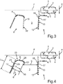
- FIG. 3 and FIG. 4 is the motor vehicle 1 shown, which has already passed the passing F at the parking space 3 and thus the parking space 3 has already passed.
- the second object 8 may be arranged obliquely with respect to the first object 7, so that the parking space 3 is not formed rectangular.
- the parking space 3 so tapers upwards.
- a first contour line 18 is determined, which extends along the depth direction T of the parking space 3 and represents the first inner side 13 of the first object 7 and the first side boundary 15 of the parking space 3. Since the sensor device 4 is arranged here in the front region of the motor vehicle 1, the second inner side 14 of the second object 8 is not in a detection range of the sensor device 4 and therefore can not be detected directly. This means that no contour points on the second inner side 14 of the second object 8 can be detected. Therefore, the second side boundary 16 of the parking space 3 represented by the second inner side 14 of the second object 8 can not be detected directly on the basis of the sensor data of the sensor device 4.
- Fig. 3 One way to estimate the second side boundary 16 of the parking space 3 is in Fig. 3 shown.
- the first contour line 18 is moved in parallel under the false assumption of objects 7, 8 arranged in parallel here.
- a contour line 19 parallel to the first contour line 18 is generated, which is assumed to represent the side boundary 16 'of the parking space 3. Due to the oblique positioning of the second object 8, however, this lateral boundary 16 'does not correspond to the actual lateral boundary 16 of the parking space 3.
- the actual orientation of the parking space 3 can therefore be determined according to FIG Fig. 3 can not be determined correctly.
- a second contour line 21 is determined, which represents the outer side 12 of the second object 8. Since the inner side 14 and the outer side 12 of the second object 8, in particular in the case of a parked motor vehicle, usually run parallel, it can be assumed that the inner side 14, which represents the actual lateral boundary 16 of the parking space 3, along one direction of the second Contour line 21 is oriented. Thus, can Based on the orientations of the contour lines 18, 21, the actual orientation of the parking space 3 are determined. Thus, the actual shape of the parking space 3 can be estimated.
- a depth direction-dependent width b of the parking space 3 can be determined by a third contour line 22 is generated by parallel displacement of the second contour line 21 by a predetermined displacement value 23.
- the third contour line 22 represents the inner side 14 of the second object 8 and thus the actual lateral boundary 16 of the parking space 3.
- the displacement value 23 can be specified as a fixed value which, for example, corresponds to the value of a standard width of a motor vehicle, in particular 1.85 m, equivalent. It can also be provided that third contour points 28 on a front side 29 of the second object 8, which faces the motor vehicle 1 while passing by the parking space 3, are determined.
- a length of the front side 29 can be determined, which corresponds to the actual distance between the outer side 12 and the inner side 14 of the second object 8.
- the shift value 23 can also be set as the value of the length of the front side 29.
- the width b of the parking space 3 can be determined.
- a depth of the parking space 3 can be determined by a length L of at least one of the contour lines 18, 21, 22 is detected.
- Fig. 5 It is shown that the outer side 12 of the second object 8, here the second motor vehicle 10, partially covered by another object 24.
- the object 24 is another motor vehicle 25, which is parked next to the parked motor vehicle 10.
- a visual beam 26 of the sensor device 4 can thus not reach a certain area 27 of the outer side 12 of the second object 8. If a length of the area of the outer side 12 detected by the sensor device 4, that is to say the length L of the second contour line 21, falls below a predetermined threshold value, then it can be assumed that the outer side 12 of the second object 8 is covered. If the length L of the second contour line 21 falls below the predetermined threshold value, it can no longer be guaranteed that the actual orientation of the parking space 3 can be correctly determined on the basis of the orientation of the second contour line 21. Therefore, in this case, the orientation of the parking space 3 is not determined on the basis of the contour lines 18, 21, 22.
Landscapes
- Engineering & Computer Science (AREA)
- Physics & Mathematics (AREA)
- Transportation (AREA)
- Mechanical Engineering (AREA)
- General Physics & Mathematics (AREA)
- Multimedia (AREA)
- Theoretical Computer Science (AREA)
- Automation & Control Theory (AREA)
- Mathematical Physics (AREA)
- Chemical & Material Sciences (AREA)
- Combustion & Propulsion (AREA)
- Traffic Control Systems (AREA)
Abstract
Description
- Die Erfindung betrifft ein Verfahren zum Charakterisieren einer von zwei Objekten begrenzten Parklücke für ein Kraftfahrzeug, bei welchem mittels einer Sensoreinrichtung des Kraftfahrzeugs Konturpunkte der Objekte während einer Vorbeifahrt des Kraftfahrzeugs an der Parklücke erfasst werden und anhand der Konturpunkte eine Orientierung der Parklücke relativ zum Kraftfahrzeug bestimmt wird. Die Erfindung betrifft außerdem ein Parkassistenzsystem sowie ein Kraftfahrzeug.
- Es ist bereits aus dem Stand der Technik bekannt, Parkassistenzsysteme für Kraftfahrzeuge bereitzustellen, welche einen Fahrer des Kraftfahrzeugs bei Parkvorgängen unterstützen können. Beispielsweise kann das Kraftfahrzeug zum Unterstützen des Fahrers durch das Parkassistenzsystem zumindest semi-autonom in eine Parklücke eingeparkt werden. Beim semi-autonomen Manövrieren übernimmt das Parkassistenzsystem des Kraftfahrzeugs eine Lenkung des Kraftfahrzeugs, während ein Fahrer des Kraftfahrzeugs das Gaspedal sowie die Bremse des Kraftfahrzeugs betätigt. Beim autonomen beziehungsweise vollautonomen Manövrieren betätigt das Parkassistenzsystem zusätzlich zu der Lenkung auch das Gaspedal, die Bremse sowie die Gangschaltung, sodass das Kraftfahrzeug automatisch gelenkt, beschleunigt und abgebremst wird.
- Um das Kraftfahrzeug dabei beschädigungsfrei einparken zu können, wird die Parklücke üblicherweise charakterisiert, beispielsweise indem eine Orientierung der Parklücke bestimmt wird. Dazu ist aus der
DE 10 2009 028 251 A1 ein Verfahren zum unterstützten Einparken in eine Parklücke bekannt. Dabei wird das Fahrzeug entlang eines ersten Abschnittes einer Einparktrajektorie bis zu einem Zwischenpunkt geführt. An dem Zwischenpunkt wird erkannt, ob die Parklücke als Parallelparklücke oder als Diagonalparklücke ausgeführt ist. Dann wird das Fahrzeug entlang eines zweiten Abschnittes der Einparktrajektorie geführt, wobei der zweite Abschnitt so gewählt wird, dass das Fahrzeug in Abhängigkeit von dem Vorliegen einer Parallelparklücke oder einer Diagonalparklücke geführt wird. - In der
DE 10 2011 113 916 A1 ist ein Verfahren zur Klassifikation von Parkszenarien für ein Parkassistenzsystem eines Kraftfahrzeugs beschrieben. Dabei ist eine vorgegebene Anzahl von Parkszenarien beschrieben, wobei jedes Parkszenario auf zumindest einem parklückenspezifischen Parameter basiert. Dabei werden Daten des Umfeldes des Kraftfahrzeugs mittels einer Umfeldsensorik bestimmt und der zumindest eine parklückenspezifische Parameter aus den Umfelddaten bestimmt. Dann wird anhand des zumindest einen parklückenspezifischen Parameters das Parkszenario klassifiziert. - Die
DE 10 2013 103 569 A1 offenbart eine Parkplatzerfassungsvorrichtung, bei welcher Konturpunkte von zwei parallel geparkten Fahrzeugen, zwischen welchen sich ein Parkplatz befindet, bestimmt werden. Basierend auf den Konturpunkten werden Eckpunkte der geparkten Fahrzeuge berechnet, anhand derer der Parkplatz erfasst wird. Dabei wird davon ausgegangen, dass die Fahrzeuge parallel geparkt sind. Falls dies nicht der Fall ist, wird während der Fahrt des Kraftfahrzeugs auf den Parkplatz eine Platzkorrekturverarbeitung durchgeführt. Daraus ergibt sich der Nachteil, dass die tatsächliche Orientierung des Parkplatzes erst erfasst wird, wenn das Kraftfahrzeug den Einparkvorgang, also die Fahrt auf den Parkplatz, bereits begonnen hat. Dabei kann es vorkommen, dass der Einparkvorgang abgebrochen werden muss, falls beispielsweise während der Fahrt auf den Parkplatz festgestellt wurde, dass die Orientierung des Parkplatzes ungeeignet für das Kraftfahrzeug ist. - Es ist Aufgabe der vorliegenden Erfindung, eine Lösung bereitzustellen, wie eine Orientierung einer Parklücke in einem Umgebungsbereich eines Kraftfahrzeugs besonders genau bestimmt werden kann, um die Parklücke zuverlässig charakterisieren zu können.
- Diese Aufgabe wird erfindungsgemäß durch ein Verfahren, durch ein Parkassistenzsystem sowie durch ein Kraftfahrzeug mit den Merkmalen gemäß den jeweiligen unabhängigen Patentansprüchen gelöst. Vorteilhafte Ausführungsformen der Erfindung sind Gegenstand der abhängigen Patentansprüche, der Beschreibung und der Figuren.
- Gemäß einer Ausführungsform eines Verfahrens zum Charakterisieren einer von zwei Objekten begrenzten Parklücke für ein Kraftfahrzeug werden mittels einer Sensoreinrichtung des Kraftfahrzeugs Konturpunkte der Objekte während einer Vorbeifahrt des Kraftfahrzeugs an der Parklücke erfasst und anhand der Konturpunkte wird eine Orientierung der Parklücke relativ zum Kraftfahrzeug bestimmt. Insbesondere werden bei einem ersten der Objekte erste Konturpunkte an einer der Parklücke zugewandten und sich entlang einer Tiefenrichtung der Parklücke erstreckenden Innenseite und/oder an einer der Parklücke abgewandten und sich entlang der Tiefenrichtung der Parklücke erstreckenden Außenseite erfasst und anhand der ersten Konturpunkte wird eine erste Konturlinie bestimmt. Bei einem zweiten der Objekte werden insbesondere zweite Konturpunkte an einer der Parklücke abgewandten und sich entlang der Tiefenrichtung der Parklücke erstreckenden Außenseite und/oder an einer der Parklücke zugewandten und sich entlang der Tiefenrichtung der Parklücke erstreckenden Innenseite erfasst und anhand der zweiten Konturpunkte wird eine zweite Konturlinie bestimmt. Anhand einer Orientierung der ersten Konturlinie und der zweiten Konturlinie kann die Orientierung der Parklücke bestimmt werden.
- Gemäß einer bevorzugten Ausführungsform eines Verfahrens zum Charakterisieren einer von zwei Objekten begrenzten Parklücke für ein Kraftfahrzeug werden mittels einer Sensoreinrichtung des Kraftfahrzeugs Konturpunkte der Objekte während einer Vorbeifahrt des Kraftfahrzeugs an der Parklücke erfasst und anhand der Konturpunkte wird eine Orientierung der Parklücke relativ zum Kraftfahrzeug bestimmt. Darüber hinaus werden bei einem ersten der Objekte erste Konturpunkte an einer der Parklücke zugewandten und sich entlang einer Tiefenrichtung der Parklücke erstreckenden Innenseite und/oder an einer der Parklücke abgewandten und sich entlang der Tiefenrichtung der Parklücke erstreckenden Außenseite erfasst und anhand der ersten Konturpunkte wird eine erste Konturlinie bestimmt. Bei einem zweiten der Objekte werden zweite Konturpunkte an einer der Parklücke abgewandten und sich entlang der Tiefenrichtung der Parklücke erstreckenden Außenseite und/oder an einer der Parklücke zugewandten und sich entlang der Tiefenrichtung der Parklücke erstreckenden Innenseite erfasst und anhand der zweiten Konturpunkte wird eine zweite Konturlinie bestimmt. Anhand einer Orientierung der ersten Konturlinie und der zweiten Konturlinie wird die Orientierung der Parklücke bestimmt.
- Mittels des Verfahrens kann ein Parkassistenzsystem für das Kraftfahrzeug realisiert werden, durch welches ein Fahrer des Kraftfahrzeugs beim Einparken in eine Parklücke unterstützt werden kann. Dazu wird die Parklücke charakterisiert, indem die Orientierung der Parklücke relativ zum Kraftfahrzeug bestimmt wird. Unter der Orientierung der Parklücke sind hier insbesondere eine Art der Parklücke, durch welche eine Fahrzeugaufstellung des Kraftfahrzeugs in der Parklücke bestimmt wird, sowie eine Form der Parklücke zu verstehen. Die Orientierung wird dabei insbesondere anhand einer Orientierung von sich entlang der Tiefenrichtung der Parklücke erstreckenden, einander gegenüberliegenden Seitenbegrenzungen der Parklücke bestimmt.
- Die Parklücke, welche durch die zwei Objekte begrenzt ist, kann dabei beispielsweise als eine Querparklücke, eine Schrägparklücke oder eine Längsparklücke ausgebildet sein. Die zwei Objekte sind insbesondere zwei parkende Kraftfahrzeuge, zwischen welchen sich die Parklücke befindet. In einer als Querparklücke ausgebildeten Parklücke weist das Kraftfahrzeug eine Senkrechtaufstellung als die Fahrzeugaufstellung auf, in einer als Schrägparklücke ausgebildeten Parklücke weist das Kraftfahrzeug eine Schrägsaufstellung als die Fahrzeugaufstellung auf und in einer als Längsparklücke ausgebildeten Parklücke weist das Kraftfahrzeug eine Längsaufstellung als die Fahrzeugaufstellung auf. Die Form der Parklücke kann im Falle von parallel zueinander positionierten, parklückenbegrenzenden Objekte eine rechteckige Form aufweisen. Im Falle von schräg zueinander positionierten, parklückenbegrenzenden Objekten kann die Form der Parklücke beispielsweise trapezförmig sein. Dies kann beispielsweise vorkommen, wenn ein geparktes Kraftfahrzeug schräg abgestellt ist, und dadurch die Parklücke beispielsweise entlang der Tiefenrichtung verjüngt ist. Dabei weist jedes der Objekte eine Außenseite, welche einen der Parklücke abgewandten Oberflächenbereich des Objektes repräsentiert, und eine Innenseite, welche einen der Parklücke zugewandten Oberflächenbereich des Objektes repräsentiert, auf. Die Innenseiten der Objekte entsprechen dabei den Seitenbegrenzungen der Parklücke. Die Innenseiten und Außenseiten erstrecken sich dabei entlang der Tiefenrichtung. Anders ausgedrückt erstrecken sich Innenseiten und Außenseiten über eine Tiefe der Parklücke. Dabei müssen die Innenseiten und Außenseiten nicht parallel zu der Tiefenrichtung orientiert sein, sondern können auch schräg zu der Tiefenrichtung orientiert sein. Im Falle einer Querparklücke oder einer Schrägparklücke, welche durch zwei parkende Kraftfahrzeuge begrenzt ist, werden die Außenseiten und die Innenseiten durch Seitenbereiche der parkenden Kraftfahrzeuge gebildet. Im Falle einer Längsparklücke, welche durch zwei parkende Kraftfahrzeuge begrenzt ist, werden die Außenseiten und die Innenseiten durch Heckbereiche bzw. Frontbereiche der parkenden Kraftfahrzeuge gebildet.
- Die Parklücke wird dabei anhand der parklückenbegrenzenden Objekte charakterisiert. Dazu werden die Konturpunkte auf sich entlang der Tiefenrichtung erstreckenden Oberflächenbereichen der Objekte mittels Sensordaten der Sensoreinrichtung erfasst. Die Sensoreinrichtung weist insbesondere eine hohe Detektionsreichweite auf. Vorzugsweise werden die Konturpunkte mittels zumindest eines Radarsensors und/oder zumindest eines Lidar-Sensors und/oder zumindest einer Kamera der Sensoreinrichtung des Kraftfahrzeugs erfasst. Durch eine Sensoreinrichtung aufweisend einen Radarsensor und/oder einen Lidar-Sensor, beispielsweise einen Laserscanner, und/oder eine Kamera können in vorteilhafter Weise detaillierte Informationen über die Objekte gewonnen werden, da solche Sensoren insbesondere eine hohe Detektionsreichweite aufweisen. Die Konturpunkte repräsentieren dabei beispielsweise sich auf der Oberfläche der Objekte befindliche Reflexionspunkte eines von der Sensoreinrichtung aus dem Umgebungsbereich empfangenen Sensorsignals. Jedem Konturpunkte kann dabei ein räumlicher Lagewert bzw. Positionswert zugeordnet werden, welcher einen Abstand sowie eine Orientierung des Reflexionspunktes auf dem jeweiligen Oberflächenbereich der Objekte zu dem Kraftfahrzeug repräsentiert.
- In einem ersten Fall können bei dem ersten Objekt die ersten Konturpunkte auf dem die Innenseite des ersten Objektes ausbildenden Oberflächenbereich und bei dem zweiten Objekt die zweiten Konturpunkte auf dem die Innenseite des zweiten Objektes ausbildenden Oberflächenbereich erfasst werden. Hier werden also bei beiden Objekten die Innenseiten erfasst. Dabei blickt die Sensoreinrichtung des Kraftfahrzeugs in die Parklücke hinein und erfasst dabei die ersten und zweiten Konturpunkte der Objekte. Anhand der ersten Konturpunkte kann, beispielsweise mittels Ausgleichsrechnung, die erste Konturlinie bestimmt werden, welche sowohl die Innenseite des ersten Objektes als auch eine erste der Seitenbegrenzungen der Parklücke repräsentiert. Anhand der zweiten Konturpunkte kann, beispielsweise mittels Ausgleichsrechnung, die zweite Konturlinie bestimmt werden, welche sowohl die Innenseite des zweiten Objektes als auch eine zweite der Seitenbegrenzungen der Parklücke repräsentiert. Aus der Erfassung der Innenseiten der Objekte ergibt sich der Vorteil, dass die Orientierungen der Seitenbegrenzungen der Parklücke direkt bestimmt werden können.
- In einem zweiten Fall können bei dem einem Objekt die Innenseite und bei dem anderen Objekt die Außenseite erfasst werden. Beispielsweise können bei dem ersten Objekt die ersten Konturpunkte auf dem die Innenseite des ersten Objektes ausbildenden Oberflächenbereich erfasst werden. Dabei blickt die Sensoreinrichtung des Kraftfahrzeugs in die Parklücke hinein und erfasst dabei die ersten Konturpunkte des ersten Objektes. Anhand dieser ersten Konturpunkte kann, beispielsweise mittels Ausgleichsrechnung, die erste Konturlinie bestimmt werden, welche sowohl die Innenseite des ersten Objektes als auch die erste Seitenbegrenzung der Parklücke repräsentiert. Bei dem zweiten Objekt werden die zweiten Konturpunkte auf der Außenseite des zweiten Objektes erfasst. Anhand dieser zweiten Konturpunkte kann, beispielsweise mittels Ausgleichsrechnung, die zweite Konturlinie bestimmt werden. Die zweite Konturlinie repräsentiert somit die Außenseite des zweiten Objektes und erstreckt sich entlang der Tiefenrichtung der Parklücke. Anhand der Orientierung der zweiten Konturlinie kann dabei auf die Orientierung der zweiten Seitenbegrenzung der Parklücke geschlossen werden. Hier wird insbesondere nämlich davon ausgegangen, dass die Außenseite des zweiten Objektes in etwa parallel zu der Innenseite des zweiten Objektes orientiert ist, wobei die Innenseite des zweiten Objektes die zweite Seitenbegrenzung der Parklücke repräsentiert. Ebenso können bei dem ersten Objekt die ersten Konturpunkte auf dem die Außenseite des ersten Objektes ausbildenden Oberflächenbereich erfasst werden und bei dem zweiten Objekt die zweiten Konturpunkte auf dem die Innenseite des zweiten Objektes ausbildenden Oberflächenbereich erfasst werden.
- Aus der Erfassung der Außenseite des einen Objektes sowie der Innenseite des anderen Objektes, welche bei der Vorbeifahrt des Kraftfahrzeugs an der Parklücke beide im Erfassungsbereich der Sensoreinrichtung liegen, ergibt sich der Vorteil, dass die Orientierungen der Seitenbegrenzungen der Parklücke mit einer besonders hohen Genauigkeit bereits vor Beginn des Einparkvorgangs während der Vorbeifahrt bestimmt werden können. Die Parklücke wird also charakterisiert, bevor der Einparkvorgang in die Parklücke gestartet wird. Anders ausgedrückt ist die Charakterisierung der Parklücke abgeschlossen, bevor das Kraftfahrzeug in die Parklücke eintaucht. Durch die Bestimmung der Orientierung der Parklücke vor Beginn des Einparkvorgangs kann in vorteilhafter Weise verhindert werden, dass der Einparkvorgang gestartet wird, wenn die Parklücke ungeeignet für das Kraftfahrzeug ist. Dies kann beispielsweise der Fall sein, wenn aufgrund der schrägen Positionierung zumindest eines der Objekte und damit aufgrund der Verjüngung der Parklücke die Breite der Parklücke nicht groß genug für das konkrete Kraftfahrzeug ist.
- In einem dritten Fall können bei dem ersten Objekt die ersten Konturpunkte auf dem die Außenseite des ersten Objektes ausbildenden Oberflächenbereich und bei dem zweiten Objekt die zweiten Konturpunkte auf dem die Außenseite des zweiten Objektes ausbildenden Oberflächenbereich erfasst werden. Hier muss die Sensoreinrichtung des Kraftfahrzeugs zum Erfassen der ersten und zweiten Konturpunkte nicht in die Parklücke hineinblicken. Anhand der ersten Konturpunkte kann, beispielsweise mittels Ausgleichsrechnung, die erste Konturlinie bestimmt werden und anhand der zweiten Konturpunkte kann, beispielsweise mittels Ausgleichsrechnung, die zweite Konturlinie bestimmt werden. Die Konturlinien repräsentieren dabei die Außenseiten der Objekte und erstrecken sich entlang der Tiefenrichtung der Parklücke. Anhand der Orientierung der Konturlinien kann dabei auf die Orientierung der Seitenbegrenzungen der Parklücke geschlossen werden. Es wird insbesondere wiederum davon ausgegangen, dass die Außenseiten der Objekte in etwa parallel zu den zugehörigen Innenseiten der Objekte orientiert sind, wobei die Innenseiten die Seitenbegrenzungen der Parklücke repräsentieren.
- Insgesamt können in vorteilhafter Weise anhand der Orientierungen der Konturlinien die Orientierungen der Seitenbegrenzungen der Parklücke und damit die Orientierung der Parklücke, insbesondere vor Beginn eines Einparkvorgangs, bestimmt werden. Wenn die Konturlinien und damit die Seitenbegrenzungen parallel zueinander orientiert sind, so kann davon ausgegangen werden, dass die Parklücke rechteckförmig ausgebildet ist. Wenn die Konturlinien und damit die Seitenbegrenzungen schräg zueinander orientiert sind, so kann davon ausgegangen werden, dass die Parklücke nicht rechteckförmig ausgebildet ist, und beispielsweise entlang der Tiefenrichtung verjüngt ist.
- Besonders bevorzugt wird im Fall, dass bei zumindest einem der Objekte die Konturpunkte an der Außenseite erfasst werden, zumindest eine dritte Konturlinie durch Parallelverschiebung der die Außenseite des Objektes repräsentierenden ersten und/oder zweiten Konturlinie um einen vorbestimmten Verschiebungswert bestimmt, durch welche eine der Parklücke zugewandte Innenseite des Objektes repräsentiert wird. Die zumindest eine dritte Konturlinie wird als eine sich in der Tiefenrichtung der Parklücke erstreckende Seitenbegrenzung der Parklücke bestimmt. Der Erfindung liegt hierbei die Erkenntnis zugrunde, dass insbesondere bei Objekten in Form von geparkten Kraftfahrzeugen die Außenseite und die Innenseite im Wesentlichen parallel zueinander verlaufen. Dabei wird die die Außenseite des ersten und/oder des zweiten Objektes charakterisierende erste und/oder zweite Konturlinie um den vorbestimmten Verschiebungswert verschoben. Dieser Verschiebungswert repräsentiert einen Abstand zwischen der Außenseite und der Innenseite des ersten und/oder des zweiten Objektes. Die zumindest eine resultierende dritte Konturlinie beschreibt die Innenseite des ersten und/oder des zweiten Objektes. Die anhand der Parallelverschiebung der ersten und/oder der zweiten Konturlinie bestimmte Innenseite des ersten und/oder des zweiten Objektes entspricht somit zumindest einer Seitenbegrenzung der Parklücke. Im Falle, dass bei einem Objekt die Außenseite und bei dem anderen Objekt die Innenseite erfasst wird, entspricht die parallelverschobene Konturlinie der ersten Seitenbegrenzung und die Konturlinie, welche anhand der Konturpunkte auf der Innenseite bestimmt wird, der zweiten Seitenbegrenzung. Anhand einer Orientierung der Seitenbegrenzungen kann dann die Orientierung der Parklücke bestimmt werden.
- Welche der sich entlang der Tiefenrichtung erstreckende Seitenbereiche der Objekte von der Sensoreinrichtung während der Vorbeifahrt des Kraftfahrzeugs an der Parklücke erfasst werden, hängt dabei insbesondere von einem Anbauort der Sensoreinrichtung am Kraftfahrzeug und einer Blickrichtung der Sensoreinrichtung ab. Beispielsweise können bei demjenigen Objekt, bei welchem die Innenseite im Erfassungsbereich der Sensoreinrichtung liegt, wenn die Sensoreinrichtung bei der Vorbeifahrt in die Parklücke blickt, die Konturpunkte auf der Innenseite erfasst werden. Bei demjenigen Objekt, bei welchem die Außenseite bei der Vorbeifahrt in dem Erfassungsbereich der Sensoreinrichtung liegt, können die Konturpunkte an der Außenseite erfasst werden.
- Im Falle einer in Fahrtrichtung des Kraftfahrzeugs blickenden Sensoreinrichtung kann beispielsweise eine die Außenseite repräsentierende Konturlinie durch Erfassen der Konturpunkte auf der Außenseite bei dem während der Vorbeifahrt zuerst von dem Kraftfahrzeug passierten Objekt bestimmt werden. Eine die Innenseite repräsentierende Konturlinie kann durch Erfassen der Konturpunkte auf der Innenseite bei dem während der Vorbeifahrt zuletzt von dem Kraftfahrzeug passierten Objekt bestimmt werden. Die Sensoreinrichtung kann hier beispielsweise in einem Frontbereich des Kraftfahrzeugs angeordnet sein und nach vorne blicken. Zum Bestimmen der dritten Konturlinie kann dabei die die Außenseite repräsentierende Konturlinie in Fahrtrichtung parallel verschoben werden.
- Im Falle einer entgegen einer Fahrtrichtung des Kraftfahrzeugs blickenden Sensoreinrichtung kann beispielsweise eine die Innenseite repräsentierende Konturlinie durch Erfassen der Konturpunkte an der Innenseite bei dem während der Vorbeifahrt zuerst von dem Kraftfahrzeug passierten Objekt bestimmt werden und eine die Außenseite repräsentierende Konturlinie durch Erfassen der Konturpunkte an der Außenseite bei dem während der Vorbeifahrt zuletzt von dem Kraftfahrzeug passierten Objekt bestimmt werden. Die Sensoreinrichtung kann hier beispielsweise in einem Heckbereich des Kraftfahrzeugs angeordnet sein und nach hinten blicken. Zum Bestimmen der dritten Konturlinie kann dabei die die Außenseite repräsentierende Konturlinie entgegen der Fahrtrichtung parallel verschoben werden.
- Im Falle, dass die Sensoreinrichtung dazu ausgelegt ist, sowohl in Fahrtrichtung als auch entgegen der Fahrtrichtung zu blicken, können von beiden Objekten die Innenseiten und die Außenseiten erfasst werden. Die Orientierungen der Seitenbegrenzungen der Parklücke können somit einmal direkt anhand der die Innenseiten repräsentierenden Konturlinien und einmal indirekt anhand der parallelverschobenen Konturlinien bestimmt werden. So kann die Orientierung der Parklücke besonders sicher und zuverlässig bestimmt werden.
- Vorzugsweise wird als der vorbestimmte Verschiebungswert ein Wert zwischen 1,55 m und 2,50 m, insbesondere 1,85 m, bestimmt. Dieser Verschiebungswert weist dabei insbesondere den Wert einer Standardbreite von Kraftfahrzeugen auf. Durch Vorgegeben des Verschiebungswertes als einen festen Zahlenwert kann die dritte Konturlinie besonders schnell und einfach mittels der Parallelverschiebung bestimmt werden.
- Auch kann vorgesehen sein, dass im Fall, dass bei zumindest einem der Objekte die Konturpunkte an der Außenseite erfasst werden, bei diesem Objekt dritte Konturpunkte an einer dem Kraftfahrzeug zugewandten Frontseite bestimmt werden, anhand der dritten Konturpunkte eine Länge der Frontseite des Objektes bestimmt wird und der Verschiebungswert als die Länge der Frontseite bestimmt wird. Die Frontseite ist insbesondere senkrecht zu der die Außenseite repräsentierenden ersten und/oder zweiten Konturlinie orientiert und grenzt an die die Außenseite repräsentierende erste und/oder zweite Konturlinie an. Bei einem Objekt in Form von einem Kraftfahrzeug, das rückwärts in einer Querparklücke geparkt ist, entspricht die Frontseite dem Frontbereich des geparkten Kraftfahrzeugs. Bei einem Kraftfahrzeug, das vorwärts in der Querparklücke geparkt ist, entspricht die Frontseite dem Heckbereich des geparkten Kraftfahrzeugs. Anhand der Länge der Frontseite kann der tatsächliche Abstand zwischen der Außenseite und der Innenseite des Objektes, also beispielsweise eine tatsächliche Breite des geparkten Kraftfahrzeugs, bestimmt werden. Dies ist besonders vorteilhaft, falls das geparkte Kraftfahrzeug eine Breite aufweist, welche nicht der Standardbreite entspricht, oder falls das geparkte Kraftfahrzeug längs geparkt ist. Beispielsweise kann vorgesehen sein, dass der Verschiebungswert zumindest 1,85 m aufweist. Nur falls die Länge der Frontseite größer als 1,85 m ist, wird der Wert der Länge der Frontseite als der Verschiebungswert vorgegeben.
- In einer Weiterbildung der Erfindung wird anhand einer räumlichen Lage der die Seitenbegrenzungen der Parklücke repräsentierenden Konturlinien eine tiefenrichtungsabhängige Breite der Parklücke bestimmt. Anders ausgedrückt wird die Breite der Parklücke über die Tiefe der Parklücke bestimmt. Die die Seitenbegrenzungen repräsentierenden Konturlinien können dabei die Konturlinien sein, welche anhand von Konturpunkten auf Innenseiten der Objekte bestimmt werden und/der welche durch Parallelverschiebung der die Außenseite repräsentierenden Konturlinien bestimmt bzw. erzeugt werden. Durch die räumliche Lage der die Seitenbegrenzungen repräsentierenden Konturlinien zueinander kann somit ein tiefenrichtungsabhängiger Abstand der Konturlinien, also der beiden Seitenbegrenzungen der Parklücke, bestimmt werden, welche die tiefenrichtungsabhängige Breite der Parklücke charakterisiert. So kann beispielsweise anhand der Konturlinien eine Verjüngung der Parklücke in Tiefenrichtung erkannt werden und somit beispielsweise vorhergesagt werden, ob die Parklücke über die gesamte Tiefe breit genug zum Aufnehmen des Kraftfahrzeugs ist.
- Gemäß einer weiteren Ausführungsform der Erfindung wird anhand einer Länge der ersten Konturlinie und/oder der zweiten Konturlinie und/oder der dritten Konturlinie als der eine Tiefe der Parklücke bestimmt. Da die Konturlinien jeweilige Seitenbegrenzungen der Parklücke beschreiben, kann anhand der Länge zumindest einer der sich in Tiefenrichtung erstreckenden Konturlinien die Tiefe der Parklücke bestimmt werden. Somit kann vor Beginn des Einparkvorgangs vorhergesagt werden, ob dich Parklücke tief genug zum Aufnehmen des Kraftfahrzeugs ist.
- Es erweist sich als vorteilhaft, wenn im Fall, dass bei zumindest einem der Objekte die Konturpunkte an der Außenseite erfasst werden, eine Länge der die Außenseite repräsentierenden ersten und/oder zweiten Konturlinie bestimmt wird und die Orientierung der Parklücke anhand der ersten und der zweiten Konturlinie nur bestimmt wird, wenn die Länge der die Außenseite repräsentierenden ersten und/oder zweiten Konturlinie einen vorbestimmen Schwellwert überschreitet. Dieser Ausführungsform liegt die Erkenntnis zugrunde, dass die die Außenseite repräsentierende erste und/oder zweite Konturlinie nur dann zuverlässig erfasst werden kann, wenn die Außenseite des betreffenden Objektes zumindest über einen vorbestimmten Bereich unverdeckt ist. Wenn beispielsweise neben dem betreffenden Objekt ein drittes Objekt positioniert ist, so kann es vorkommen, dass das dritte Objekt die Außenseite des betreffenden Objektes zumindest bereichsweise abdeckt bzw. abschirmt. Dies kann beispielsweise vorkommen, wenn neben dem betreffenden Objekt in Form von einem geparkten Kraftfahrzeug ein weiteres Kraftfahrzeug geparkt ist. Wenn die Länge der die Außenseite repräsentierenden ersten und/oder zweiten Konturlinie den vorbestimmten Schwellwert unterschreitet, so ist dies ein Indiz dafür, dass die Außenseite des betreffenden Objekte zumindest bereichsweise verdeckt ist. Um nun zu verhindern, dass die Parklücke fehlerhaft charakterisiert wird, wird die Orientierung der Parklücke nicht anhand der Konturlinien bestimmt, falls die Länge der die Außenseite repräsentierenden ersten und/oder zweiten Konturlinie den vorbestimmten Schwellwert unterschreitet.
- Die Erfindung betrifft außerdem ein Parkassistenzsystem für ein Kraftfahrzeug zum Unterstützen eines Fahrers des Kraftfahrzeugs beim Einparken in eine von zwei Objekten begrenzte Parklücke. Gemäß einer Ausführungsform weist das Parkassistenzsystem insbesondere eine Sensoreinrichtung zum Erfassen von Konturpunkten der Objekte während einer Vorbeifahrt des Kraftfahrzeugs an der Parklücke und eine Steuereinrichtung zum Bestimmen einer Orientierung der Parklücke relativ zum Kraftfahrzeug anhand der Konturpunkte auf. Die Sensoreinrichtung ist insbesondere dazu ausgelegt, bei einem ersten der Objekte erste Konturpunkte an einer der Parklücke zugewandten und sich entlang der Tiefenrichtung der Parklücke erstreckenden Innenseite und/oder an einer der Parklücke abgewandten und sich entlang der Tiefenrichtung der Parklücke erstreckenden Außenseite zu erfassen und bei einem zweiten der Objekte zweite Konturpunkte an einer der Parklücke abgewandten und sich entlang einer Tiefenrichtung der Parklücke erstreckenden Außenseite und/oder an einer der Parklücke zugewandten und sich entlang der Tiefenrichtung der Parklücke erstreckenden Innenseite zu erfassen. Die Steuereinrichtung ist insbesondere dazu ausgelegt, anhand der ersten Konturpunkte eine erste Konturlinie und anhand der zweiten Konturpunkte eine zweite Konturlinie zu bestimmen, und anhand einer räumlichen Lage der ersten Konturlinie und der zweiten Konturlinie die Orientierung der Parklücke zu bestimmen.
- Gemäß einer besonders bevorzugten Ausführungsform weist das Parkassistenzsystem eine Sensoreinrichtung zum Erfassen von Konturpunkten der Objekte während einer Vorbeifahrt des Kraftfahrzeugs an der Parklücke und eine Steuereinrichtung zum Bestimmen einer Orientierung der Parklücke relativ zum Kraftfahrzeug anhand der Konturpunkte auf. Die Sensoreinrichtung ist dazu ausgelegt, bei einem ersten der Objekte erste Konturpunkte an einer der Parklücke zugewandten und sich entlang der Tiefenrichtung der Parklücke erstreckenden Innenseite und/oder an einer der Parklücke abgewandten und sich entlang der Tiefenrichtung der Parklücke erstreckenden Außenseite zu erfassen und bei einem zweiten der Objekte zweite Konturpunkte an einer der Parklücke abgewandten und sich entlang einer Tiefenrichtung der Parklücke erstreckenden Außenseite und/oder an einer der Parklücke zugewandten und sich entlang der Tiefenrichtung der Parklücke erstreckenden Innenseite zu erfassen. Die Steuereinrichtung ist dazu ausgelegt, anhand der ersten Konturpunkte eine erste Konturlinie und anhand der zweiten Konturpunkte eine zweite Konturlinie zu bestimmen, und anhand einer räumlichen Lage der ersten Konturlinie und der zweiten Konturlinie die Orientierung der Parklücke zu bestimmen.
- Vorzugsweise ist die Steuereinrichtung dazu ausgelegt, unter Berücksichtigung der Orientierung der Parklücke eine Einparktrajektorie für das Kraftfahrzeug in die Parklücke zu bestimmen. Die Einparktrajektorie wird insbesondere dann bestimmt, wenn anhand der Konturlinien erkannt wurde, dass die Parklücke geeignet für das Kraftfahrzeug ist, also beispielsweise über die gesamte Tiefe der Parklücke breit genug für das Kraftfahrzeug ist. Beispielsweise kann die Einparktrajektorie ausgehend von einem Startpunkt bestimmt werden, an welchem sich das Kraftfahrzeug nach der Vorbeifahrt an der Parklücke befindet. Die Einparktrajektorie kann dem Fahrer des Kraftfahrzeugs beispielsweise auf einer fahrzeugseitigen Anzeigeeinrichtung angezeigt werden, sodass der Fahrer das Kraftfahrzeug entlang der angezeigten Einparktrajektorie in die Parklücke manövrieren kann. Außerdem kann vorgesehen sein, dass die Steuereinrichtung dazu ausgelegt ist, das Kraftfahrzeug zumindest semi-autonom, insbesondere vollautonom, entlang der bestimmten Einparktrajektorie in die Parklücke zu manövrieren. Dazu kann die Steuereinrichtung in eine Längsführung und eine Querführung des Kraftfahrzeugs eingreifen.
- Ein erfindungsgemäßes Kraftfahrzeug umfasst ein erfindungsgemäßes Parkassistenzsystem. Das Kraftfahrzeug ist insbesondere als ein Personenkraftwagen ausgebildet.
- Die mit Bezug auf das erfindungsgemäße Verfahren vorgestellten bevorzugten Ausführungsformen und deren Vorteile gelten entsprechend für das erfindungsgemäße Parkassistenzsystem sowie für das erfindungsgemäße Kraftfahrzeug.
- Weitere Merkmale der Erfindung ergeben sich aus den Ansprüchen, den Figuren und der Figurenbeschreibung. Die vorstehend in der Beschreibung genannten Merkmale und Merkmalskombinationen, sowie die nachfolgend in der Figurenbeschreibung genannten und/oder in den Figuren alleine gezeigten Merkmale und Merkmalskombinationen sind nicht nur in der jeweils angegebenen Kombination, sondern auch in anderen Kombinationen oder in Alleinstellung verwendbar, ohne den Rahmen der Erfindung zu verlassen. Es sind somit auch Ausführungen von der Erfindung als umfasst und offenbart anzusehen, die in den Figuren nicht explizit gezeigt und erläutert sind, jedoch durch separierte Merkmalskombinationen aus den erläuterten Ausführungen hervorgehen und erzeugbar sind. Es sind auch Ausführungen und Merkmalskombinationen als offenbart anzusehen, die somit nicht alle Merkmale eines ursprünglich formulierten unabhängigen Anspruchs aufweisen. Es sind darüber hinaus Ausführungen und Merkmalskombinationen, insbesondere durch die oben dargelegten Ausführungen, als offenbart anzusehen, die über die in den Rückbezügen der Ansprüche dargelegten Merkmalskombinationen hinausgehen oder abweichen.
- Die Erfindung wird nun anhand von bevorzugten Ausführungsbeispielen sowie unter Bezugnahme auf die beigefügten Zeichnungen näher erläutert.
- Dabei zeigen:
- Fig. 1
- eine schematische Darstellung einer Ausführungsform eines erfindungsgemäßen Kraftfahrzeugs beim Vorbeifahren an einer Parklücke;
- Fig. 2
- eine schematische Darstellung einer Parkfläche mit zwei parallel positionierten Objekten und einer sich dazwischen befindlichen Parklücke;
- Fig. 3
- eine schematische Darstellung eines Kraftfahrzeugs beim Erfassen einer fehlerhaften Orientierung einer Parklücke;
- Fig. 4
- eine schematische Darstellung des Kraftfahrzeugs beim Erfassen einer korrekten, tatsächlichen Orientierung einer Parklücke; und
- Fig. 5
- eine schematische Darstellung des erfindungsgemäßen Kraftfahrzeugs beim Vorbeifahren an einer Parklücke einer Parkfläche, auf welcher mehrere Objekte positioniert sind.
- In den Figuren sind gleiche sowie funktionsgleiche Elemente mit den gleichen Bezugszeichen versehen.
-
Fig. 1 zeigt ein Kraftfahrzeug 1 gemäß der vorliegenden Erfindung. Das Kraftfahrzeug 1 ist im vorliegenden Fall als ein Personenkraftwagen ausgebildet. Das Kraftfahrzeug 1 weist ein Parkassistenzsystem 2 auf, welches einen Fahrer des Kraftfahrzeugs 1 beim Einparken in eine Parklücke 3 unterstützen kann. Dazu weist das Parkassistenzsystem 2 eine Sensoreinrichtung 4 auf, welche im vorliegenden Fall in einem Frontbereich des Kraftfahrzeugs 1 angeordnet ist und in Vorwärtsrichtung blicken kann. Die Sensoreinrichtung 4 kann beispielsweise zumindest einen Radarsensor und/oder zumindest einen Lidar-Sensor und/oder zumindest eine Kamera aufweisen. Mittels der fahrzeugseitigen Sensoreinrichtung 4 kann ein Umgebungsbereich 5 des Kraftfahrzeugs 1 überwacht werden, indem aus dem Umgebungsbereich 5 Sensordaten erfasst werden. Beispielsweise kann die Sensoreinrichtung 4 bei einer Vorbeifahrt F des Kraftfahrzeugs 1 an der Parklücke 3 Sensordaten erfassen, anhand derer die Parklücke 3 charakterisiert werden kann. Außerdem weist das Parkassistenzsystem 2 eine Steuereinrichtung 6 auf, welche beispielsweise in ein Steuergerät des Kraftfahrzeugs 1 integriert sein kann. - Die Steuereinrichtung 6 kann die Sensordaten der Sensoreinrichtung 4 auswerten, um die Parklücke 3 zu charakterisieren. Beispielsweise kann eine Orientierung der Parklücke 3 relativ zum Kraftfahrzeug 1 bestimmt werden. Außerdem kann die Steuereinrichtung 6 dazu ausgelegt sein, in Abhängigkeit von der Orientierung der Parklücke 3 eine Einparktrajektorie für das Kraftfahrzeug 1 in die Parklücke 3 bestimmen, entlang welcher das Kraftfahrzeug 1 in die Parklücke 3 eingeparkt werden kann. Beispielsweise kann die Steuereinrichtung 6 das Kraftfahrzeug 1 zumindest semi-autonom entlang der Einparktrajektorie in die Parklücke 3 einparken. Die Parklücke 3 ist hier durch zwei Objekte 7, 8 begrenzt, wobei die Objekte 7, 8 im vorliegenden Fall als geparkte Kraftfahrzeuge 9, 10 ausgebildet sind. Hier ist die Parklücke 3 als eine rechteckförmige Schrägparklücke ausgebildet und nach rechts hin durch ein erstes Objekt 7, hier durch ein erstes geparktes Kraftfahrzeug 9, und nach links hin durch ein zweites Objekt 8, hier durch ein zweites geparktes Kraftfahrzeug 10, begrenzt. Anhand der Objekte 7, 8 kann die Orientierung der Parklücke 3 bestimmt werden.
- In
Fig. 2 sind die Objekte 7, 8 schematisch dargestellt, wobei die Objekte 7, 8 hier parallel zueinander positioniert sind. Zwischen den Objekten 7, 8 befindet sich die Parklücke 3, welche im vorliegenden Fall als eine rechteckförmige Querparklücke ausgebildet ist. Jedes Objekt 7, 8 weist dabei eine der Parklücke 3 abgewandte Außenseite 11, 12 auf. Außerdem weist jedes Objekt 7, 8 eine Innenseite 13, 14 auf, welche der Parklücke 3 zugewandt ist und die Parklücke 3 begrenzt. Die Außenseiten 11, 12 und Innenseiten 13, 14 der Objekte 7, 8 erstrecken sich dabei entlang einer Tiefenrichtung T der Parklücke 3. Die sich entlang der Tiefenrichtung T erstreckenden Außenseiten 11, 12 und Innenseiten 13, 14 müssen dabei nicht parallel zu der Tiefenrichtung T orientiert sein. Die Innenseiten 13, 14 entsprechen dabei Seitenbegrenzungen 15, 16 der Parklücke 3, welche sich ebenfalls in Tiefenrichtung T der Parklücke 3 erstrecken. Eine erste Innenseite 13 des ersten Objektes 7 begrenzt die Parklücke 3 hier nach rechts hin. Die erste Innenseite 13 entspricht also einer ersten Seitenbegrenzung 15. Eine zweite Innenseite 14 des zweiten Objektes 8 begrenzt die Parklücke 3 hier nach links hin. Die zweite Innenseite 14 entspricht also einer zweiten Seitenbegrenzung 16. Im Falle von Objekten 7, 8, welche als in Querparklücken oder Schrägparklücken geparkte Kraftfahrzeuge 9, 10 ausgebildet sind, entsprechen die Außenseiten 11, 12 und Innenseiten 13, 14 Seitenbereichen der Kraftfahrzeuge 9, 10. - In
Fig. 3 und Fig. 4 ist das Kraftfahrzeug 1 dargestellt, welches die Vorbeifahrt F an der Parklücke 3 bereits durchgeführt hat und somit die Parklücke 3 bereits passiert hat. Hier sind die Objekte 7, 8, von denen hier lediglich Bereiche einer Kontur K dargestellt sind, nicht parallel zueinander positioniert. Beispielsweise kann das zweite Objekt 8 schräg bezüglich des ersten Objektes 7 angeordnet sein, sodass die Parklücke 3 nicht rechteckförmig ausgebildet ist. Hier ist die Parklücke 3 also nach oben hin verjüngt. Durch die Sensoreinrichtung 4, welche während der Vorbeifahrt F an der Parklücke 3 in die Parklücke 3 geblickt hat, wurden hier erste Konturpunkte 17 an der der Parklücke 3 zugewandten ersten Innenseite 13 des ersten Objektes 7 erfasst. Anhand der ersten Konturpunkte 17 wird eine erste Konturlinie 18 bestimmt, welche sich entlang der Tiefenrichtung T der Parklücke 3 erstreckt und die erste Innenseite 13 des ersten Objektes 7 sowie die erste Seitenbegrenzung 15 der Parklücke 3 repräsentiert. Da die Sensoreinrichtung 4 hier im Frontbereich des Kraftfahrzeugs 1 angeordnet ist, befindet sich die zweite Innenseite 14 des zweiten Objektes 8 nicht in einem Erfassungsbereich der Sensoreinrichtung 4 und kann daher nicht direkt erfasst werden. Dies bedeutet, dass keine Konturpunkte an der zweiten Innenseite 14 des zweiten Objektes 8 erfasst werden können. Daher kann die durch die zweite Innenseite 14 des zweiten Objektes 8 repräsentierte zweite Seitenbegrenzung 16 der Parklücke 3 nicht direkt anhand der Sensordaten der Sensoreinrichtung 4 erfasst werden. - Eine Möglichkeit, die zweite Seitenbegrenzung 16 der Parklücke 3 abzuschätzen, ist in
Fig. 3 gezeigt. Dabei wird die erste Konturlinie 18 unter der hier falschen Annahme von parallel angeordneten Objekten 7, 8 parallel verschoben. Dadurch wird eine zu der ersten Konturlinie 18 parallele Konturlinie 19 erzeugt, von welcher angenommen wird, dass sie die Seitenbegrenzung 16' der Parklücke 3 repräsentiert. Diese Seitenbegrenzung 16' entspricht jedoch aufgrund der schrägen Positionierung des zweiten Objektes 8 nicht der tatsächlichen Seitenbegrenzung 16 der Parklücke 3. Die tatsächliche Orientierung der Parklücke 3 kann somit gemäßFig. 3 nicht korrekt bestimmt werden. - Daher werden, wie in
Fig. 4 gezeigt, zusätzlich zu den ersten Konturpunkten 17 des ersten Objektes 7 zweite Konturpunkte 20 an der Außenseite 12 des zweiten Objektes 8 erfasst. Anhand der zweiten Konturpunkte 20 wird eine zweite Konturlinie 21 bestimmt, welche die Außenseite 12 des zweiten Objektes 8 repräsentiert. Da die Innenseite 14 und die Außenseite 12 des zweiten Objektes 8, insbesondere im Falle von einem geparkten Kraftfahrzeug, üblicherweise parallel verlaufen, kann davon ausgegangen werden, dass die Innenseite 14, welche die tatsächliche Seitenbegrenzung 16 der Parklücke 3 repräsentiert, entlang einer Richtung der zweiten Konturlinie 21 orientiert ist. Somit kann anhand der Orientierungen der Konturlinien 18, 21 die tatsächliche Orientierung der Parklücke 3 bestimmt werden. Es kann also die tatsächliche Form der Parklücke 3 abgeschätzt werden. - Außerdem kann eine tiefenrichtungsabhängige Breite b der Parklücke 3 bestimmt werden, indem eine dritte Konturlinie 22 durch Parallelverschiebung der zweiten Konturlinie 21 um einen vorbestimmten Verschiebungswert 23 erzeugt wird. Die dritte Konturlinie 22 repräsentiert dabei die Innenseite 14 des zweiten Objektes 8 und damit die tatsächliche Seitenbegrenzung 16 der Parklücke 3. Der Verschiebungswert 23 kann dabei als ein fester Wert vorgegeben werden, welcher beispielsweise dem Wert einer Standardbreite eines Kraftfahrzeugs, insbesondere 1,85 m, entspricht. Auch kann vorgesehen sein, dass dritte Konturpunkte 28 an einer Frontseite 29 des zweiten Objektes 8, welche dem Kraftfahrzeug 1 während der Vorbeifahrt F an der Parklücke 3 zugewandt ist, bestimmt werden. Anhand der dritten Konturpunkte 28 kann eine Länge der Frontseite 29 bestimmt werden, welche dem tatsächlichen Abstand zwischen der Außenseite 12 und der Innenseite 14 des zweiten Objektes 8 entspricht. Somit kann der Verschiebungswert 23 auch als der Wert der Länge der Frontseite 29 vorgegeben werden. Anhand von räumlichen Lagen der ersten Konturlinie 18 und der dritten Konturlinie 21 zueinander, insbesondere anhand deren tiefenrichtungsabhängigem Abstand, kann die Breite b der Parklücke 3 bestimmt werden. Auch kann eine Tiefe der Parklücke 3 bestimmt werden, indem eine Länge L zumindest einer der Konturlinien 18, 21, 22 erfasst wird.
- In
Fig. 5 ist gezeigt, dass die Außenseite 12 des zweiten Objektes 8, hier des zweiten Kraftfahrzeugs 10, bereichsweise durch ein anderes Objekt 24 verdeckt ist. Hier ist das Objekt 24 ein anderes Kraftfahrzeug 25, welches neben dem geparkten Kraftfahrzeug 10 geparkt ist. Ein Sehstrahl 26 der Sensoreinrichtung 4 kann somit einen bestimmen Bereich 27 der Außenseite 12 des zweiten Objektes 8 nicht erreichen. Falls eine Länge des von der Sensoreinrichtung 4 detektierten Bereiches der Außenseite 12, also die Länge L der zweiten Konturlinie 21, einen vorbestimmen Schwellwert unterschreitet, so kann davon ausgegangen werden, dass die Außenseite 12 des zweiten Objektes 8 verdeckt ist. Wenn die Länge L der zweiten Konturlinie 21 den vorbestimmten Schwellwert unterschreitet, kann nicht mehr gewährleistet werden, dass anhand der Orientierung der zweiten Konturlinie 21 die tatsächliche Orientierung der Parklücke 3 korrekt bestimmt werden kann. Daher wird in diesem Fall die Orientierung der Parklücke 3 nicht anhand der Konturlinien 18, 21, 22 bestimmt.
Claims (11)
- Verfahren zum Charakterisieren einer von zwei Objekten (7, 8) begrenzten Parklücke (3) für ein Kraftfahrzeug (1), bei welchem mittels einer Sensoreinrichtung (4) des Kraftfahrzeugs (1) Konturpunkte der Objekte (7, 8) während einer Vorbeifahrt (F) des Kraftfahrzeugs (1) an der Parklücke (3) erfasst werden und anhand der Konturpunkte eine Orientierung der Parklücke (3) relativ zum Kraftfahrzeug (1) bestimmt wird,
dadurch gekennzeichnet, dass- bei einem ersten der Objekte (7) erste Konturpunkte (17) an einer der Parklücke (3) zugewandten und sich entlang einer Tiefenrichtung (T) der Parklücke (3) erstreckenden Innenseite (13) und/oder an einer der Parklücke (3) abgewandten und sich entlang der Tiefenrichtung (T) der Parklücke (3) erstreckenden Außenseite (11) erfasst werden und anhand der ersten Konturpunkte (17) eine erste Konturlinie (18) bestimmt wird,- bei einem zweiten der Objekte (8) zweite Konturpunkte (20) an einer der Parklücke (3) abgewandten und sich entlang der Tiefenrichtung (T) der Parklücke (3) erstreckenden Außenseite (12) und/oder an einer der Parklücke (3) zugewandten und sich entlang der Tiefenrichtung (T) der Parklücke (3) erstreckenden Innenseite (14) erfasst werden und anhand der zweiten Konturpunkte (20) eine zweite Konturlinie (21) bestimmt wird,- anhand einer Orientierung der ersten Konturlinie (18) und der zweiten Konturlinie (21) die Orientierung der Parklücke (3) bestimmt wird. - Verfahren nach Anspruch 1,
dadurch gekennzeichnet, dass
im Fall, dass bei zumindest einem der Objekte (7, 8) die Konturpunkte (17, 20) an der Außenseite (11, 12) erfasst werden, zumindest eine dritte Konturlinie (22) durch Parallelverschiebung der die Außenseite (11, 12) des Objektes (7, 8) repräsentierenden ersten und/oder zweiten Konturlinie (18, 21) um einen vorbestimmten Verschiebungswert (23) bestimmt wird, durch welche eine der Parklücke (3) zugewandte Innenseite (13, 14) des Objektes (7, 8) repräsentiert wird, und die zumindest eine dritte Konturlinie (18, 21) als eine sich in der Tiefenrichtung (T) der Parklücke (3) erstreckende Seitenbegrenzung (15, 16) der Parklücke (3) bestimmt wird. - Verfahren nach Anspruch 2,
dadurch gekennzeichnet, dass
als der vorbestimmte Verschiebungswert (23) ein Wert zwischen 1,55 m und 2,50 m, insbesondere 1,85 m, bestimmt wird. - Verfahren nach Anspruch 2 oder 3,
dadurch gekennzeichnet, dass
im Fall, dass bei zumindest einem der Objekte (7, 8) die Konturpunkte (17, 20) an der Außenseite (11, 12) erfasst werden, bei diesem Objekt (7, 8) dritte Konturpunkte (28) an einer dem Kraftfahrzeug (1) zugewandten Frontseite (29) bestimmt werden, anhand der dritten Konturpunkte (28) eine Länge der Frontseite (29) des Objektes (8) bestimmt wird und der Verschiebungswert (23) als die Länge der Frontseite (29) bestimmt wird. - Verfahren nach einem der Ansprüche 2 bis 4,
dadurch gekennzeichnet, dass
anhand einer räumlichen Lage der die Seitenbegrenzungen (15, 16) der Parklücke (3) repräsentierenden Konturlinien (18, 22) eine tiefenrichtungsabhängige Breite (b) der Parklücke (3) bestimmt wird. - Verfahren nach einem der Ansprüche 2 bis 5,
dadurch gekennzeichnet, dass
anhand einer Länge der ersten Konturlinie (18) und/oder der zweiten Konturlinie (21) und/oder der dritten Konturlinie (22) eine Tiefe der Parklücke (3) bestimmt wird. - Verfahren nach einem der vorhergehenden Ansprüche,
dadurch gekennzeichnet, dass
die Konturpunkte (17, 20) mittels zumindest eines Radarsensors und/oder zumindest eines Lidar-Sensors und/oder zumindest einer Kamera der Sensoreinrichtung (4) des Kraftfahrzeugs (1) erfasst werden. - Verfahren nach einem der vorhergehenden Ansprüche,
dadurch gekennzeichnet, dass
im Fall, dass bei zumindest einem der Objekte (7, 8) die Konturpunkte (17, 20) an der Außenseite (11, 12) erfasst werden, eine Länge (L) der die Außenseite (11, 12) repräsentierenden ersten und/oder zweiten Konturlinie (18, 21) bestimmt wird und die Orientierung der Parklücke (3) anhand der ersten und der zweiten Konturlinie (18, 21) nur bestimmt wird, wenn die Länge (L) der die Außenseite (11, 12) repräsentierenden ersten und/oder zweiten Konturlinie (18, 21) einen vorbestimmen Schwellwert überschreitet. - Parkassistenzsystem (2) für ein Kraftfahrzeug (1) zum Unterstützen eines Fahrers des Kraftfahrzeugs (1) beim Einparken in eine von zwei Objekten (7, 8) begrenzte Parklücke (3), aufweisend eine Sensoreinrichtung (4) zum Erfassen von Konturpunkten der Objekte (7, 8) während einer Vorbeifahrt (F) des Kraftfahrzeugs (1) an der Parklücke (3) und eine Steuereinrichtung (6) zum Bestimmen einer Orientierung der Parklücke (3) relativ zum Kraftfahrzeug (1) anhand der Konturpunkte,
dadurch gekennzeichnet, dass- die Sensoreinrichtung (4) dazu ausgelegt ist, bei einem ersten der Objekte (7) erste Konturpunkte (17) an einer der Parklücke (3) zugewandten und sich entlang der Tiefenrichtung (T) der Parklücke (3) erstreckenden Innenseite (13) und/oder an einer der Parklücke (3) abgewandten und sich entlang der Tiefenrichtung (T) der Parklücke (3) erstreckenden Außenseite (11) zu erfassen und bei einem zweiten der Objekte (8) zweite Konturpunkte (20) an einer der Parklücke (3) abgewandten und sich entlang einer Tiefenrichtung (T) der Parklücke (3) erstreckenden Außenseite (12) und/oder an einer der Parklücke (3) zugewandten und sich entlang der Tiefenrichtung (T) der Parklücke (3) erstreckenden Innenseite (14) zu erfassen, und- die Steuereinrichtung (6) dazu ausgelegt ist, anhand der ersten Konturpunkte (17) eine erste Konturlinie (18) und anhand der zweiten Konturpunkte (20) eine zweite Konturlinie (21) zu bestimmen, und anhand einer räumlichen Lage der ersten Konturlinie (18) und der zweiten Konturlinie (21) die Orientierung der Parklücke (3) zu bestimmen. - Parkassistenzsystem (2) nach Anspruch 9,
dadurch gekennzeichnet, dass
die Steuereinrichtung (6) dazu ausgelegt ist, unter Berücksichtigung der Orientierung der Parklücke (3) eine Einparktrajektorie für das Kraftfahrzeug (1) in die Parklücke (3) zu bestimmen. - Kraftfahrzeug (1) mit einem Parkassistenzsystem (2) nach Anspruch 9 oder 10.
Applications Claiming Priority (1)
| Application Number | Priority Date | Filing Date | Title |
|---|---|---|---|
| DE102017120765.1A DE102017120765A1 (de) | 2017-09-08 | 2017-09-08 | Verfahren zum Charakterisieren einer von zwei Objekten begrenzten Parklücke für ein Kraftfahrzeug, Parkassistenzsystem sowie Kraftfahrzeug |
Publications (2)
| Publication Number | Publication Date |
|---|---|
| EP3453595A1 true EP3453595A1 (de) | 2019-03-13 |
| EP3453595B1 EP3453595B1 (de) | 2020-09-09 |
Family
ID=63350402
Family Applications (1)
| Application Number | Title | Priority Date | Filing Date |
|---|---|---|---|
| EP18189924.6A Active EP3453595B1 (de) | 2017-09-08 | 2018-08-21 | Verfahren zum charakterisieren einer von zwei objekten begrenzten parklücke für ein kraftfahrzeug, parkassistenzsystem sowie kraftfahrzeug |
Country Status (3)
| Country | Link |
|---|---|
| EP (1) | EP3453595B1 (de) |
| CN (1) | CN109466544B (de) |
| DE (1) | DE102017120765A1 (de) |
Cited By (4)
| Publication number | Priority date | Publication date | Assignee | Title |
|---|---|---|---|---|
| US20210031755A1 (en) * | 2019-07-29 | 2021-02-04 | Clarion Co., Ltd. | Parking assistance device and control method of parking assistance device |
| US20220379882A1 (en) * | 2021-05-28 | 2022-12-01 | Jaguar Land Rover Limited | Apparatus and method for controlling vehicle movement |
| WO2023027113A1 (ja) * | 2021-08-27 | 2023-03-02 | 株式会社デンソー | 物体検知装置および物体検知プログラム |
| CN116653923A (zh) * | 2023-04-27 | 2023-08-29 | 东风汽车集团股份有限公司 | 一种基于虚拟车位的自动泊车方法 |
Families Citing this family (3)
| Publication number | Priority date | Publication date | Assignee | Title |
|---|---|---|---|---|
| CN110111603B (zh) * | 2019-05-10 | 2021-05-18 | 广州达泊智能科技有限公司 | 基于三维检测技术的停车辅助方法、装置及系统 |
| JP7785448B2 (ja) * | 2020-09-29 | 2025-12-15 | 株式会社アイシン | 駐車支援システム、駐車支援装置、駐車支援方法、及びプログラム |
| CN114001695B (zh) * | 2021-11-10 | 2023-10-03 | 济南维优科技开发有限公司 | 一种在线检测铁路站场防溜停车器制动轨形态轮廓的方法 |
Citations (2)
| Publication number | Priority date | Publication date | Assignee | Title |
|---|---|---|---|---|
| JP2002228734A (ja) * | 2001-02-05 | 2002-08-14 | Nissan Motor Co Ltd | 周囲物体認識装置 |
| DE102013103569A1 (de) * | 2012-04-17 | 2013-10-17 | Denso Corporation | Parkplatzerfassungsvorrichtung |
Family Cites Families (13)
| Publication number | Priority date | Publication date | Assignee | Title |
|---|---|---|---|---|
| FR2749670B1 (fr) * | 1996-06-11 | 1998-07-31 | Renault | Dispositif et procede de mesure de creneaux de stationnement d'un vehicule automobile |
| JP2002243857A (ja) * | 2001-02-14 | 2002-08-28 | Nissan Motor Co Ltd | 周囲物体認識装置 |
| DE10325709A1 (de) * | 2003-06-06 | 2004-12-23 | Valeo Schalter Und Sensoren Gmbh | Vorrichtung und Verfahren zum Erkennen des Konturverlaufes eines Hindernisses |
| JP2006193011A (ja) * | 2005-01-12 | 2006-07-27 | Toyota Motor Corp | 駐車支援装置 |
| WO2009033286A1 (en) * | 2007-09-14 | 2009-03-19 | Magna International Inc. | Object detection and ranging method |
| DE102008027779A1 (de) * | 2008-06-11 | 2009-12-17 | Valeo Schalter Und Sensoren Gmbh | Verfahren zur Unterstützung eines Fahrers eines Fahrzeugs beim Einparken in eine Parklücke |
| DE102009028251A1 (de) * | 2009-08-05 | 2011-02-10 | Robert Bosch Gmbh | Verfahren zum unterstützen Einparken in eine Parklücke und Vorrichtung hierzu |
| DE102011113916A1 (de) * | 2011-09-21 | 2013-03-21 | Volkswagen Aktiengesellschaft | Verfahren zur Klassifikation von Parkszenarien für ein Einparksystem eines Kraftfahrzeugs |
| JP5857900B2 (ja) * | 2012-07-18 | 2016-02-10 | アイシン精機株式会社 | 駐車支援装置 |
| DE102013114563A1 (de) * | 2013-12-19 | 2015-06-25 | Valeo Schalter Und Sensoren Gmbh | Verfahren zum Durchführen eines Einparkvorgangs eines Kraftfahrzeugs in eine Querparklücke, Parkassistenzsystem und Kraftfahrzeug |
| JP6278920B2 (ja) * | 2015-03-23 | 2018-02-14 | 三菱電機株式会社 | 駐車支援装置 |
| JP6544121B2 (ja) * | 2015-07-31 | 2019-07-17 | アイシン精機株式会社 | 駐車支援装置 |
| WO2017060975A1 (ja) * | 2015-10-06 | 2017-04-13 | 三菱電機株式会社 | 駐車形態判定装置 |
-
2017
- 2017-09-08 DE DE102017120765.1A patent/DE102017120765A1/de not_active Withdrawn
-
2018
- 2018-08-21 EP EP18189924.6A patent/EP3453595B1/de active Active
- 2018-09-07 CN CN201811041794.0A patent/CN109466544B/zh active Active
Patent Citations (2)
| Publication number | Priority date | Publication date | Assignee | Title |
|---|---|---|---|---|
| JP2002228734A (ja) * | 2001-02-05 | 2002-08-14 | Nissan Motor Co Ltd | 周囲物体認識装置 |
| DE102013103569A1 (de) * | 2012-04-17 | 2013-10-17 | Denso Corporation | Parkplatzerfassungsvorrichtung |
Cited By (6)
| Publication number | Priority date | Publication date | Assignee | Title |
|---|---|---|---|---|
| US20210031755A1 (en) * | 2019-07-29 | 2021-02-04 | Clarion Co., Ltd. | Parking assistance device and control method of parking assistance device |
| US11465613B2 (en) * | 2019-07-29 | 2022-10-11 | Clarion Co., Ltd. | Parking assistance device and control method of parking assistance device |
| US20220379882A1 (en) * | 2021-05-28 | 2022-12-01 | Jaguar Land Rover Limited | Apparatus and method for controlling vehicle movement |
| WO2023027113A1 (ja) * | 2021-08-27 | 2023-03-02 | 株式会社デンソー | 物体検知装置および物体検知プログラム |
| JP2023032737A (ja) * | 2021-08-27 | 2023-03-09 | 株式会社デンソー | 物体検知装置および物体検知プログラム |
| CN116653923A (zh) * | 2023-04-27 | 2023-08-29 | 东风汽车集团股份有限公司 | 一种基于虚拟车位的自动泊车方法 |
Also Published As
| Publication number | Publication date |
|---|---|
| CN109466544B (zh) | 2022-10-28 |
| CN109466544A (zh) | 2019-03-15 |
| DE102017120765A1 (de) | 2019-03-14 |
| EP3453595B1 (de) | 2020-09-09 |
Similar Documents
| Publication | Publication Date | Title |
|---|---|---|
| EP2920778B1 (de) | Verfahren zum durchführen eines zumindest semi-autonomen parkvorgangs eines kraftfahrzeugs in eine garage, parkassistenzsystem und kraftfahrzeug | |
| EP3453595B1 (de) | Verfahren zum charakterisieren einer von zwei objekten begrenzten parklücke für ein kraftfahrzeug, parkassistenzsystem sowie kraftfahrzeug | |
| EP3086993B1 (de) | Verfahren zum durchführen eines einparkvorgangs eines kraftfahrzeugs in eine querparklücke, parkassistenzsystem und kraftfahrzeug | |
| EP2517190B1 (de) | Automatisches vorwärtseinparken in kopfparklücken | |
| DE102009006331B4 (de) | Robuste Ein- und Ausparkstrategie | |
| EP2282922B1 (de) | Verfahren zur unterstützung eines fahrers eines fahrzeugs beim einparken in eine parklücke | |
| EP3219582B1 (de) | Verfahren zum zumindest semi-autonomen einparken eines kraftfahrzeugs, fahrerassistenzsystem sowie kraftfahrzeug | |
| EP2626279B1 (de) | Fahrerassistenzsystem zur Anpassung der Zielposition in Querparklücken durch den Fahrer | |
| DE102017215565A1 (de) | Verfahren zum automatischen Vorwärts- oder Rückwärtseinparken sowie Einparkassistent | |
| WO2019030094A1 (de) | Verfahren zum überwachen eines umgebungsbereiches eines kraftfahrzeugs, sensorsteuergerät, fahrerassistenzsystem sowie kraftfahrzeug | |
| WO2011018321A1 (de) | Kollisionsüberwachung für ein kraftfahrzeug | |
| EP3418163A2 (de) | Automatisches einparken nach einem abgebrochenen manuellen einparkvorgang | |
| DE102016117712A1 (de) | Verfahren zum zumindest semi-autonomen Manövrieren eines Kraftfahrzeugs unter Berücksichtigung eines Erfassungsbereichs eines Sensors, Fahrerassistenzsystem sowie Kraftfahrzeug | |
| DE102018201447A1 (de) | Unfallvermeidung mit dem Querverkehr bei einem automatisierten Einparkvorgang in eine Querparklücke | |
| EP3431369A1 (de) | Verfahren zum längseinparken eines kraftfahrzeugs in eine längsparklücke, wobei abstandsschwellwerte verringert werden, parkassistenzsystem sowie kraftfahrzeug | |
| DE102019123797A1 (de) | Verfahren zum Erkennen einer Tretbewegung hinter einem Fahrzeug zum Öffnen dessen Kofferraumtür | |
| DE102018103698A1 (de) | Straßenabtastverfahren | |
| DE102013010729B4 (de) | Verfahren zum Abbrechen eines automatischen Fahrmodus eines Kraftfahrzeugs, Fahrerassistenzeinrichtung und Kraftfahrzeug | |
| EP3199429B1 (de) | Verfahren zum verfahren zum unterstützen eines fahrers eines kraftfahrzeugs bei einem einparkvorgang in eine parklücke mit bordstein, fahrerassistenzsystem sowie kraftfahrzeug | |
| DE102020121785B4 (de) | Verfahren zum Manövrieren eines Fahrzeugs in eine Schrägparklücke mit Vermeidung einer Kollision einer Frontschürze des Fahrzeugs mit einer Begrenzung der Schrägparklücke, Fahrerassistenzsystem sowie Fahrzeug | |
| DE102009046677A1 (de) | Einparkverfahren mit einem Fahrerassistenzsystem | |
| DE102017108857A1 (de) | Verfahren zum Einparken an einem Bordstein | |
| WO2019020586A1 (de) | Verfahren zum zumindest semi-autonomen einparken eines kraftfahrzeugs, fahrerassistenzsystem sowie kraftfahrzeug | |
| DE102023004414B3 (de) | Verfahren zum automatischen Queren eines Kreuzungsbereichs und Fahrzeug | |
| EP3219583B1 (de) | Verfahren zum zumindest semi-autonomen einparken eines kraftfahrzeugs, fahrerassistenzsystem sowie kraftfahrzeug |
Legal Events
| Date | Code | Title | Description |
|---|---|---|---|
| PUAI | Public reference made under article 153(3) epc to a published international application that has entered the european phase |
Free format text: ORIGINAL CODE: 0009012 |
|
| STAA | Information on the status of an ep patent application or granted ep patent |
Free format text: STATUS: THE APPLICATION HAS BEEN PUBLISHED |
|
| AK | Designated contracting states |
Kind code of ref document: A1 Designated state(s): AL AT BE BG CH CY CZ DE DK EE ES FI FR GB GR HR HU IE IS IT LI LT LU LV MC MK MT NL NO PL PT RO RS SE SI SK SM TR |
|
| AX | Request for extension of the european patent |
Extension state: BA ME |
|
| STAA | Information on the status of an ep patent application or granted ep patent |
Free format text: STATUS: REQUEST FOR EXAMINATION WAS MADE |
|
| 17P | Request for examination filed |
Effective date: 20190912 |
|
| RBV | Designated contracting states (corrected) |
Designated state(s): AL AT BE BG CH CY CZ DE DK EE ES FI FR GB GR HR HU IE IS IT LI LT LU LV MC MK MT NL NO PL PT RO RS SE SI SK SM TR |
|
| GRAP | Despatch of communication of intention to grant a patent |
Free format text: ORIGINAL CODE: EPIDOSNIGR1 |
|
| STAA | Information on the status of an ep patent application or granted ep patent |
Free format text: STATUS: GRANT OF PATENT IS INTENDED |
|
| INTG | Intention to grant announced |
Effective date: 20200424 |
|
| GRAS | Grant fee paid |
Free format text: ORIGINAL CODE: EPIDOSNIGR3 |
|
| GRAA | (expected) grant |
Free format text: ORIGINAL CODE: 0009210 |
|
| STAA | Information on the status of an ep patent application or granted ep patent |
Free format text: STATUS: THE PATENT HAS BEEN GRANTED |
|
| AK | Designated contracting states |
Kind code of ref document: B1 Designated state(s): AL AT BE BG CH CY CZ DE DK EE ES FI FR GB GR HR HU IE IS IT LI LT LU LV MC MK MT NL NO PL PT RO RS SE SI SK SM TR |
|
| REG | Reference to a national code |
Ref country code: GB Ref legal event code: FG4D Free format text: NOT ENGLISH |
|
| REG | Reference to a national code |
Ref country code: AT Ref legal event code: REF Ref document number: 1311249 Country of ref document: AT Kind code of ref document: T Effective date: 20200915 Ref country code: CH Ref legal event code: EP |
|
| REG | Reference to a national code |
Ref country code: IE Ref legal event code: FG4D Free format text: LANGUAGE OF EP DOCUMENT: GERMAN |
|
| REG | Reference to a national code |
Ref country code: DE Ref legal event code: R096 Ref document number: 502018002376 Country of ref document: DE |
|
| REG | Reference to a national code |
Ref country code: LT Ref legal event code: MG4D |
|
| PG25 | Lapsed in a contracting state [announced via postgrant information from national office to epo] |
Ref country code: FI Free format text: LAPSE BECAUSE OF FAILURE TO SUBMIT A TRANSLATION OF THE DESCRIPTION OR TO PAY THE FEE WITHIN THE PRESCRIBED TIME-LIMIT Effective date: 20200909 Ref country code: BG Free format text: LAPSE BECAUSE OF FAILURE TO SUBMIT A TRANSLATION OF THE DESCRIPTION OR TO PAY THE FEE WITHIN THE PRESCRIBED TIME-LIMIT Effective date: 20201209 Ref country code: SE Free format text: LAPSE BECAUSE OF FAILURE TO SUBMIT A TRANSLATION OF THE DESCRIPTION OR TO PAY THE FEE WITHIN THE PRESCRIBED TIME-LIMIT Effective date: 20200909 Ref country code: NO Free format text: LAPSE BECAUSE OF FAILURE TO SUBMIT A TRANSLATION OF THE DESCRIPTION OR TO PAY THE FEE WITHIN THE PRESCRIBED TIME-LIMIT Effective date: 20201209 Ref country code: HR Free format text: LAPSE BECAUSE OF FAILURE TO SUBMIT A TRANSLATION OF THE DESCRIPTION OR TO PAY THE FEE WITHIN THE PRESCRIBED TIME-LIMIT Effective date: 20200909 Ref country code: GR Free format text: LAPSE BECAUSE OF FAILURE TO SUBMIT A TRANSLATION OF THE DESCRIPTION OR TO PAY THE FEE WITHIN THE PRESCRIBED TIME-LIMIT Effective date: 20201210 Ref country code: LT Free format text: LAPSE BECAUSE OF FAILURE TO SUBMIT A TRANSLATION OF THE DESCRIPTION OR TO PAY THE FEE WITHIN THE PRESCRIBED TIME-LIMIT Effective date: 20200909 |
|
| REG | Reference to a national code |
Ref country code: NL Ref legal event code: MP Effective date: 20200909 |
|
| PG25 | Lapsed in a contracting state [announced via postgrant information from national office to epo] |
Ref country code: PL Free format text: LAPSE BECAUSE OF FAILURE TO SUBMIT A TRANSLATION OF THE DESCRIPTION OR TO PAY THE FEE WITHIN THE PRESCRIBED TIME-LIMIT Effective date: 20200909 Ref country code: LV Free format text: LAPSE BECAUSE OF FAILURE TO SUBMIT A TRANSLATION OF THE DESCRIPTION OR TO PAY THE FEE WITHIN THE PRESCRIBED TIME-LIMIT Effective date: 20200909 Ref country code: RS Free format text: LAPSE BECAUSE OF FAILURE TO SUBMIT A TRANSLATION OF THE DESCRIPTION OR TO PAY THE FEE WITHIN THE PRESCRIBED TIME-LIMIT Effective date: 20200909 |
|
| PG25 | Lapsed in a contracting state [announced via postgrant information from national office to epo] |
Ref country code: SM Free format text: LAPSE BECAUSE OF FAILURE TO SUBMIT A TRANSLATION OF THE DESCRIPTION OR TO PAY THE FEE WITHIN THE PRESCRIBED TIME-LIMIT Effective date: 20200909 Ref country code: CZ Free format text: LAPSE BECAUSE OF FAILURE TO SUBMIT A TRANSLATION OF THE DESCRIPTION OR TO PAY THE FEE WITHIN THE PRESCRIBED TIME-LIMIT Effective date: 20200909 Ref country code: PT Free format text: LAPSE BECAUSE OF FAILURE TO SUBMIT A TRANSLATION OF THE DESCRIPTION OR TO PAY THE FEE WITHIN THE PRESCRIBED TIME-LIMIT Effective date: 20210111 Ref country code: RO Free format text: LAPSE BECAUSE OF FAILURE TO SUBMIT A TRANSLATION OF THE DESCRIPTION OR TO PAY THE FEE WITHIN THE PRESCRIBED TIME-LIMIT Effective date: 20200909 Ref country code: EE Free format text: LAPSE BECAUSE OF FAILURE TO SUBMIT A TRANSLATION OF THE DESCRIPTION OR TO PAY THE FEE WITHIN THE PRESCRIBED TIME-LIMIT Effective date: 20200909 |
|
| PG25 | Lapsed in a contracting state [announced via postgrant information from national office to epo] |
Ref country code: IS Free format text: LAPSE BECAUSE OF FAILURE TO SUBMIT A TRANSLATION OF THE DESCRIPTION OR TO PAY THE FEE WITHIN THE PRESCRIBED TIME-LIMIT Effective date: 20210109 Ref country code: AL Free format text: LAPSE BECAUSE OF FAILURE TO SUBMIT A TRANSLATION OF THE DESCRIPTION OR TO PAY THE FEE WITHIN THE PRESCRIBED TIME-LIMIT Effective date: 20200909 Ref country code: ES Free format text: LAPSE BECAUSE OF FAILURE TO SUBMIT A TRANSLATION OF THE DESCRIPTION OR TO PAY THE FEE WITHIN THE PRESCRIBED TIME-LIMIT Effective date: 20200909 |
|
| REG | Reference to a national code |
Ref country code: DE Ref legal event code: R097 Ref document number: 502018002376 Country of ref document: DE |
|
| PG25 | Lapsed in a contracting state [announced via postgrant information from national office to epo] |
Ref country code: SK Free format text: LAPSE BECAUSE OF FAILURE TO SUBMIT A TRANSLATION OF THE DESCRIPTION OR TO PAY THE FEE WITHIN THE PRESCRIBED TIME-LIMIT Effective date: 20200909 |
|
| PLBE | No opposition filed within time limit |
Free format text: ORIGINAL CODE: 0009261 |
|
| STAA | Information on the status of an ep patent application or granted ep patent |
Free format text: STATUS: NO OPPOSITION FILED WITHIN TIME LIMIT |
|
| 26N | No opposition filed |
Effective date: 20210610 |
|
| PG25 | Lapsed in a contracting state [announced via postgrant information from national office to epo] |
Ref country code: SI Free format text: LAPSE BECAUSE OF FAILURE TO SUBMIT A TRANSLATION OF THE DESCRIPTION OR TO PAY THE FEE WITHIN THE PRESCRIBED TIME-LIMIT Effective date: 20200909 Ref country code: DK Free format text: LAPSE BECAUSE OF FAILURE TO SUBMIT A TRANSLATION OF THE DESCRIPTION OR TO PAY THE FEE WITHIN THE PRESCRIBED TIME-LIMIT Effective date: 20200909 |
|
| PG25 | Lapsed in a contracting state [announced via postgrant information from national office to epo] |
Ref country code: IT Free format text: LAPSE BECAUSE OF FAILURE TO SUBMIT A TRANSLATION OF THE DESCRIPTION OR TO PAY THE FEE WITHIN THE PRESCRIBED TIME-LIMIT Effective date: 20200909 |
|
| REG | Reference to a national code |
Ref country code: CH Ref legal event code: PL |
|
| PG25 | Lapsed in a contracting state [announced via postgrant information from national office to epo] |
Ref country code: MC Free format text: LAPSE BECAUSE OF FAILURE TO SUBMIT A TRANSLATION OF THE DESCRIPTION OR TO PAY THE FEE WITHIN THE PRESCRIBED TIME-LIMIT Effective date: 20200909 |
|
| REG | Reference to a national code |
Ref country code: BE Ref legal event code: MM Effective date: 20210831 |
|
| PG25 | Lapsed in a contracting state [announced via postgrant information from national office to epo] |
Ref country code: LI Free format text: LAPSE BECAUSE OF NON-PAYMENT OF DUE FEES Effective date: 20210831 Ref country code: CH Free format text: LAPSE BECAUSE OF NON-PAYMENT OF DUE FEES Effective date: 20210831 |
|
| PG25 | Lapsed in a contracting state [announced via postgrant information from national office to epo] |
Ref country code: LU Free format text: LAPSE BECAUSE OF NON-PAYMENT OF DUE FEES Effective date: 20210821 |
|
| PG25 | Lapsed in a contracting state [announced via postgrant information from national office to epo] |
Ref country code: IE Free format text: LAPSE BECAUSE OF NON-PAYMENT OF DUE FEES Effective date: 20210821 Ref country code: BE Free format text: LAPSE BECAUSE OF NON-PAYMENT OF DUE FEES Effective date: 20210831 |
|
| PG25 | Lapsed in a contracting state [announced via postgrant information from national office to epo] |
Ref country code: NL Free format text: LAPSE BECAUSE OF NON-PAYMENT OF DUE FEES Effective date: 20200923 Ref country code: CY Free format text: LAPSE BECAUSE OF FAILURE TO SUBMIT A TRANSLATION OF THE DESCRIPTION OR TO PAY THE FEE WITHIN THE PRESCRIBED TIME-LIMIT Effective date: 20200909 |
|
| P01 | Opt-out of the competence of the unified patent court (upc) registered |
Effective date: 20230528 |
|
| PG25 | Lapsed in a contracting state [announced via postgrant information from national office to epo] |
Ref country code: HU Free format text: LAPSE BECAUSE OF FAILURE TO SUBMIT A TRANSLATION OF THE DESCRIPTION OR TO PAY THE FEE WITHIN THE PRESCRIBED TIME-LIMIT; INVALID AB INITIO Effective date: 20180821 |
|
| PG25 | Lapsed in a contracting state [announced via postgrant information from national office to epo] |
Ref country code: MK Free format text: LAPSE BECAUSE OF FAILURE TO SUBMIT A TRANSLATION OF THE DESCRIPTION OR TO PAY THE FEE WITHIN THE PRESCRIBED TIME-LIMIT Effective date: 20200909 |
|
| PG25 | Lapsed in a contracting state [announced via postgrant information from national office to epo] |
Ref country code: MT Free format text: LAPSE BECAUSE OF FAILURE TO SUBMIT A TRANSLATION OF THE DESCRIPTION OR TO PAY THE FEE WITHIN THE PRESCRIBED TIME-LIMIT Effective date: 20200909 |
|
| REG | Reference to a national code |
Ref country code: AT Ref legal event code: MM01 Ref document number: 1311249 Country of ref document: AT Kind code of ref document: T Effective date: 20230821 |
|
| PG25 | Lapsed in a contracting state [announced via postgrant information from national office to epo] |
Ref country code: AT Free format text: LAPSE BECAUSE OF NON-PAYMENT OF DUE FEES Effective date: 20230821 |
|
| PG25 | Lapsed in a contracting state [announced via postgrant information from national office to epo] |
Ref country code: AT Free format text: LAPSE BECAUSE OF NON-PAYMENT OF DUE FEES Effective date: 20230821 |
|
| PGFP | Annual fee paid to national office [announced via postgrant information from national office to epo] |
Ref country code: DE Payment date: 20250812 Year of fee payment: 8 |
|
| PGFP | Annual fee paid to national office [announced via postgrant information from national office to epo] |
Ref country code: GB Payment date: 20250826 Year of fee payment: 8 |
|
| PGFP | Annual fee paid to national office [announced via postgrant information from national office to epo] |
Ref country code: FR Payment date: 20250828 Year of fee payment: 8 |
|
| PG25 | Lapsed in a contracting state [announced via postgrant information from national office to epo] |
Ref country code: TR Free format text: LAPSE BECAUSE OF FAILURE TO SUBMIT A TRANSLATION OF THE DESCRIPTION OR TO PAY THE FEE WITHIN THE PRESCRIBED TIME-LIMIT Effective date: 20200909 |
|
| PGFP | Annual fee paid to national office [announced via postgrant information from national office to epo] |
Ref country code: AT Payment date: 20260410 Year of fee payment: 5 |