EP3453292A1 - Bouilloire munie d'au moins deux débits de versage - Google Patents
Bouilloire munie d'au moins deux débits de versage Download PDFInfo
- Publication number
- EP3453292A1 EP3453292A1 EP18187149.2A EP18187149A EP3453292A1 EP 3453292 A1 EP3453292 A1 EP 3453292A1 EP 18187149 A EP18187149 A EP 18187149A EP 3453292 A1 EP3453292 A1 EP 3453292A1
- Authority
- EP
- European Patent Office
- Prior art keywords
- shutter
- kettle
- pouring
- openings
- opening
- Prior art date
- Legal status (The legal status is an assumption and is not a legal conclusion. Google has not performed a legal analysis and makes no representation as to the accuracy of the status listed.)
- Withdrawn
Links
Images

Classifications
-
- A—HUMAN NECESSITIES
- A47—FURNITURE; DOMESTIC ARTICLES OR APPLIANCES; COFFEE MILLS; SPICE MILLS; SUCTION CLEANERS IN GENERAL
- A47J—KITCHEN EQUIPMENT; COFFEE MILLS; SPICE MILLS; APPARATUS FOR MAKING BEVERAGES
- A47J27/00—Cooking-vessels
- A47J27/21—Water-boiling vessels, e.g. kettles
- A47J27/21008—Water-boiling vessels, e.g. kettles electrically heated
-
- A—HUMAN NECESSITIES
- A47—FURNITURE; DOMESTIC ARTICLES OR APPLIANCES; COFFEE MILLS; SPICE MILLS; SUCTION CLEANERS IN GENERAL
- A47J—KITCHEN EQUIPMENT; COFFEE MILLS; SPICE MILLS; APPARATUS FOR MAKING BEVERAGES
- A47J27/00—Cooking-vessels
- A47J27/21—Water-boiling vessels, e.g. kettles
- A47J27/21166—Constructional details or accessories
- A47J27/21175—Covers
-
- A—HUMAN NECESSITIES
- A47—FURNITURE; DOMESTIC ARTICLES OR APPLIANCES; COFFEE MILLS; SPICE MILLS; SUCTION CLEANERS IN GENERAL
- A47J—KITCHEN EQUIPMENT; COFFEE MILLS; SPICE MILLS; APPARATUS FOR MAKING BEVERAGES
- A47J27/00—Cooking-vessels
- A47J27/21—Water-boiling vessels, e.g. kettles
- A47J27/21166—Constructional details or accessories
- A47J27/21191—Pouring spouts
-
- A—HUMAN NECESSITIES
- A47—FURNITURE; DOMESTIC ARTICLES OR APPLIANCES; COFFEE MILLS; SPICE MILLS; SUCTION CLEANERS IN GENERAL
- A47J—KITCHEN EQUIPMENT; COFFEE MILLS; SPICE MILLS; APPARATUS FOR MAKING BEVERAGES
- A47J41/00—Thermally-insulated vessels, e.g. flasks, jugs, jars
- A47J41/0005—Thermally-insulated vessels, e.g. flasks, jugs, jars comprising a single opening for filling and dispensing provided with a stopper
- A47J41/0016—Thermally-insulated vessels, e.g. flasks, jugs, jars comprising a single opening for filling and dispensing provided with a stopper the stopper remaining in the opening and clearing a passage way between stopper and vessel for dispensing
- A47J41/0022—Thermally-insulated vessels, e.g. flasks, jugs, jars comprising a single opening for filling and dispensing provided with a stopper the stopper remaining in the opening and clearing a passage way between stopper and vessel for dispensing the stopper comprising two or more pieces movable relatively to each other for opening or closing the dispensing passage
Definitions
- the present invention relates to a liquid heating apparatus, in particular an electric kettle, comprising an electric heating base, a body and a lid forming an enclosure intended to bring water to a boil, and more particularly a kettle whose pouring flow rate. is adjustable.
- a kettle comprising a body arranged above an electric heating bottom and a lid forming an enclosure for bringing water to a boil, the kettle comprising a water pouring duct and a shutter movable between a position closure of the pouring duct and at least one opening position of the pouring duct.
- the kettle has shutter actuating means which includes a push button. More or less pressing the button moves the shutter from the closed position to the open position through several intermediate positions in which the user can obtain several pouring rates.
- the intermediate positions of the shutter are not stable positions which allow a calibrated and repetitive pouring flow from one use to another.
- the user is encouraged to open the shutter in the maximum open position and manage the pouring rate by tilting more or less the kettle.
- An object of the present invention is to overcome the aforementioned drawbacks and to provide a kettle which has a simple and ergonomic implementation and safe use.
- Another object of the present invention is to provide a kettle which has a simple design and that is economical to implement.
- a kettle comprising a body arranged above an electric heating bottom and a lid forming an enclosure for bringing water to a boil, said kettle comprising a water pouring conduit and a device movable shutter between a closed position of the pouring duct and at least one opening position of the pouring duct, characterized in that a wall, comprising at least first and second through openings, is arranged transversely to the duct pouring and in that the closure device is movable between a closed position of the pouring conduit in which the closure device closes the first and second through openings, a first open position defining a first pouring rate in which the shutter device releases only the first through opening and a second open position defining a second th pouring rate in which the shutter device releases the first and second through openings.
- through opening there is a through opening or a group of through openings.
- the first through opening has a first passage section of the hot water which defines a first pouring rate when the closure device is in the first open position.
- the second through opening has a second section of the hot water passage which accumulated with the first passage section defines a second pouring rate when the closure device is in the second open position.
- the first flow will include a restricted flow which allows a high accuracy of pouring and the second flow will rather be a large flow that allows a rapid filling of a container.
- the ratio between the first section and the sum of the first and second sections is less than 0.3.
- the wall is arranged in the cover.
- This arrangement allows to position the flow management function in the lid, without complicating the body of the kettle.
- the wall is part of a bottom wall of the lid.
- the lid has a spout.
- the end of the pouring channel which is formed by the spout is also integrated in the lid.
- the shutter device comprises a shutter.
- one piece allows to close or release the first and second through openings.
- the shutter is movable in translation in a direction A.
- a translation is an easy movement to implement in the kettle, which simplifies its design.
- the shutter comprises a stud extending in the direction A and having a cross section identical to a section of the second through opening, the stud being adapted to slide in the second through opening between the closed position or the first position opening, wherein the stud is arranged in the second through opening, to the second open position, wherein the stud is translated outside the second through opening.
- the stud closes the second through opening and to pass into the second position defining the second pouring flow, the sliding block to release the second through opening.
- the shutter comprises a valve provided with a seal, the valve provided with the seal closing the first and second openings when the shutter is in the closed position.
- This arrangement makes it possible to obtain a tight closure of the kettle, especially in the event of a rollover.
- the kettle comprises a shutter control button, the control button being movable in rotation and having three stable positions.
- control button comprises a cam comprising two sectors of different slopes.
- the first and second through openings are cylindrical.
- Such a construction allows in particular an easy adjustment of the stud in the second through opening.
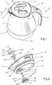
- a kettle 1 comprises a base 2 electrically powered by a cord (not shown in the figures) and a body 3 forming a receptacle for water.
- the body 3 comprises an upper filling opening 4 which is closed by a lid 10.
- the lid 10 comprises a spout 11 located at the top opening 4.
- the kettle 1 comprises a handle 5 located opposite the spout pourer 11 relative to the upper opening.
- the body 3 has a substantially cylindrical shape comprising a vertical axis 70.
- the cover 10 is removable relative to the body 3 and the cover 10 is intended to be assembled sealingly on the body 3 in a translational movement substantially parallel to the vertical axis 70 of the body 3.
- the body 3 comprises a heating base formed of a stainless steel cup in which are arranged an aluminum diffuser and a heating element (not shown in the figures).
- the body 3 provided with the heating bottom and the lid 10 forms an enclosure for carrying water to a boil.
- the lid 10 comprises a lower housing 12, an intermediate portion 13 and an upper housing 14.
- the lid 10 comprises a pouring duct 15 of the hot water ( Fig.4 ) and the spout 11 forms an outlet end of the pouring duct 15.
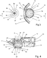
- the pouring duct 15 comprises a wall 16 provided with 6 first through openings 6a, 6b, 6c, 6d, 6e, 6f and 18 second through openings 7a , 7b, 7c, ..., 7r through which hot water can pass ( Fig.3 ).
- the first 6 through openings 6a, 6b, 6c, 6d, 6e, 6f and the second through openings 7a, 7b, 7c, ..., 7r are identical and cylindrical.
- the wall 16 is substantially horizontal and is part of a bottom wall 17 of the lower housing 12.
- the wall 16 forms an inlet end of the pouring duct 15.
- On the figure 4 an arrow illustrates the path followed by the hot water in the pouring duct 15.
- the lid 10 comprises a closure device comprising a shutter 20 movable in translation along a direction A, parallel to the vertical axis 70 and perpendicular to a horizontal plane in which the wall 16 extends.
- the shutter 20 comprises a valve 21 arranged under the wall 16.
- the valve 21 takes the form of a disk and comprises a peripheral seal 22 intended to cooperate with the wall 16.
- the valve 21 comprises an upper face 23 from which extend 18 studs 8a, 8b, 8c ..., 8r according to the direction A ( Fig.3 ).
- Each stud 8a, ..., 8r is intended to cooperate with a second through opening 7a, ..., 7r.
- Each stud 8a, ..., 8r is cylindrical and has a cross section identical to a section of each of the second through openings 7a, ..., 7r.
- the shutter 20 is movable between a closed position of the pouring duct 15 in which the valve 21 provided with the seal 22 closes the first 6 through openings 6a, ..., 6f and 18 second through openings 7a,. .., 7r ( Fig.4 ) and two opening positions ( Fig.5 and 6 ).
- a first open position defines a first pouring flow in which the 18 studs 8a, ..., 8r close the second through openings 7a, ..., 7r, the shutter 20 releasing only the first 6 through openings 6a, ..., 6f.
- the first pouring rate is defined by the sum of the sections of the 6 through openings 6a, ..., 6f released by the shutter.
- This group of 6 through openings 6a, ..., 6f is equivalent to a first through opening.
- a dotted arrow illustrates the path followed by the hot water in the pouring duct 15.
- a second open position defines a second pouring rate in which the shutter releases the second through openings 7a, ..., 7r in addition to the first 6 through openings already released in the first open position.
- the group of 18 second through openings 7a, ..., 7r is equivalent to a second through opening.
- the second pouring rate is defined by the sum of the sections of the first 6 through openings 6a, ..., 6f and 18 second through openings 7a, ..., 7r released by the shutter.
- the large number of first 6 through openings 6a, ..., 6f and second through openings 7a, ..., 7r makes it possible to limit the speed of the hot water flow in the pouring conduit 15, both in the first open position than in the second open position.
- a dotted arrow illustrates the path followed by the hot water in the pouring duct 15.
- Each stud 8a, ..., 8r is adapted to slide in the corresponding second through opening 7a, ..., 7r between the closed position or the first open position in which the stud 8a, ..., 8r is arranged in the second through opening 7a, ..., 7r towards the second open position in which the stud 8a, ..., 8r is translated outside the second through opening 7a, ..., 7r, towards the inside the kettle enclosure 1.
- the shutter 20 comprises a rod 24 extending from the upper face 23 of the valve 21 in the direction A.
- An actuator 25 is arranged on a free end of the rod 24.
- a guide element 26 ( Fig.4 ) arranged in the intermediate portion 13 of the cover 10, serves to guide the actuator 25 in translation in the direction A, and the rod 24, the valve 21 and the pads 8a, ..., 8r.
- the wall 16 also comprises a guide opening 27 in translation of the rod 24, the valve 21 and the pads 8a, ..., 8r.
- a control button 30 of the shutter 20 is arranged in the cover 10.
- the control button 30 is movable in rotation and has three stable positions: a central position, an upright position and a left position.
- the control button 30 comprises a cylindrical cam 31 ( Fig. 2 ) whose profile comprises two sectors 31a, 31b of different slopes.
- the cam 31 cooperates with a pusher 28 secured to the actuator 25.
- the sector 31a having the lowest slope cooperates with the pusher 28 to pass the shutter 20 in its first open position.
- the sector 31b with the largest slope cooperates with the pusher 28 to pass the shutter 20 in its second open position.
- the sectors 31a, 31b are arranged head to tail.
- the central position of the control button 31 corresponds to the closing position of the shutter 20.
- a clockwise rotation of the control knob 30 moves it to its right position and causes the shutter 20 to go into its first position. opening position while a rotation in the anti direction time of the control button 30 moves it to its left position and passes the shutter 20 in its second open position.
- a return spring 29 ( Fig.4 ) is arranged between the guiding element 26 and the actuator 25 to bring the pusher 28 into contact with the cam 31.
- the shutter 20 In operation, when the control knob 30 is in the central position, the shutter 20 is in its closed position of the pouring duct 15 and the first 6 through-openings 6a, ..., 6f and the second through-openings 7a, ..., 7r are closed.
- the user who wants to pour the hot water with a reduced flow turns the control knob 31 to the right position to pass the shutter 20 in its first open position.
- the first open position defines a first reduced flow rate in which the valve 21 by translating releases the first 6 through openings 6a, ..., 6f.
- the 18 studs 8a, ..., 8r of the valve 21 translate into the second through openings 7a, ..., 7r and keep them closed.
- the user can then grasp the handle 5 of the kettle 1 and pour hot water into a container with a reduced flow rate.
- the user who wants to pour the hot water with a high flow turns the control knob 30 to the left position to pass the shutter 20 in its second open position.
- the second open position defines a second large pouring flow in which the 18 studs 8a, ..., 8r of the valve 21 translate outside the second through openings 7a, ..., 7r to release them in addition to the 6 first through openings 6a, ..., 6f already released in the first open position.
- the user can then grab the handle 5 of the kettle 1 and pour hot water into a container with a high flow rate.
- the shutter is movable in translation in a direction parallel to an extension plane of the wall having the first and second through openings.
- the closure device comprises a first shutter that closes or releases the first through opening and a second shutter that closes or releases the second through opening.
- the wall comprises, in addition to first and second through openings, a third through opening.
- the movable shutter device has a third open position defining a third pouring rate in which the shutter device releases the first, second and third through openings.
- the closure device may comprise a shutter provided with a second stud which cooperates with the third through opening, the second stud being longer than the stud cooperating with the second through opening.
- the control button may comprise a cam comprising a third sector of slope different from the first two.
Landscapes
- Engineering & Computer Science (AREA)
- Food Science & Technology (AREA)
- Cookers (AREA)
Applications Claiming Priority (1)
| Application Number | Priority Date | Filing Date | Title |
|---|---|---|---|
| FR1758274A FR3070586B1 (fr) | 2017-09-07 | 2017-09-07 | Bouilloire munie d'au moins deux debits de versage |
Publications (1)
| Publication Number | Publication Date |
|---|---|
| EP3453292A1 true EP3453292A1 (fr) | 2019-03-13 |
Family
ID=60450819
Family Applications (1)
| Application Number | Title | Priority Date | Filing Date |
|---|---|---|---|
| EP18187149.2A Withdrawn EP3453292A1 (fr) | 2017-09-07 | 2018-08-02 | Bouilloire munie d'au moins deux débits de versage |
Country Status (4)
| Country | Link |
|---|---|
| EP (1) | EP3453292A1 (zh) |
| JP (1) | JP7222624B2 (zh) |
| CN (1) | CN109464004B (zh) |
| FR (1) | FR3070586B1 (zh) |
Cited By (1)
| Publication number | Priority date | Publication date | Assignee | Title |
|---|---|---|---|---|
| FR3120184A1 (fr) * | 2021-02-26 | 2022-09-02 | Seb S.A. | Appareil de preparation de boissons muni d’un couvercle ameliore |
Families Citing this family (1)
| Publication number | Priority date | Publication date | Assignee | Title |
|---|---|---|---|---|
| JP6829282B2 (ja) * | 2019-05-16 | 2021-02-10 | 象印マホービン株式会社 | 飲料供給器 |
Citations (5)
| Publication number | Priority date | Publication date | Assignee | Title |
|---|---|---|---|---|
| FR2756476A1 (fr) * | 1996-12-04 | 1998-06-05 | Moulinex Sa | Bouilloire electrique comprenant un recipient dont le debouche est ferme par un couvercle |
| WO2001032063A1 (fr) * | 1999-11-02 | 2001-05-10 | Seb Sa | Recipient a dispositif d'obturation a plusieurs positions, en particulier bouilloire electrique |
| WO2005107539A1 (fr) * | 2004-04-07 | 2005-11-17 | Seb S.A. | Appareil electrique de chauffage de liquide |
| CN201564130U (zh) * | 2009-11-04 | 2010-09-01 | 广州市拓璞电器发展有限公司 | 一种壶嘴结构 |
| GB2471552A (en) * | 2009-06-26 | 2011-01-05 | Tsann Kuen | A kettle discharge attachment |
Family Cites Families (7)
| Publication number | Priority date | Publication date | Assignee | Title |
|---|---|---|---|---|
| JP3913227B2 (ja) | 2004-03-29 | 2007-05-09 | サーモス株式会社 | 飲料容器の栓体 |
| GB2445026B (en) * | 2006-12-22 | 2011-08-10 | Salton Europ Ltd | Improvements in and relating to lids for domestic appliances |
| JP2009178413A (ja) | 2008-01-31 | 2009-08-13 | Tiger Vacuum Bottle Co Ltd | 電気ケトル |
| JP2013233225A (ja) | 2012-05-07 | 2013-11-21 | Hitachi Living Supply:Kk | 電気ケトル |
| FR3006875B1 (fr) * | 2013-06-14 | 2015-06-05 | Seb Sa | Bouilloire munie d'un ensemble filtre et clapet anti-poussiere amovible |
| FR3021198B1 (fr) * | 2014-05-23 | 2016-05-13 | Seb Sa | Dispositif et procede de production et de distribution de liquide en ebullition et appareil de preparation de boisson equipe d'un tel dispositif |
| CN104997396A (zh) * | 2015-07-13 | 2015-10-28 | 中山市美斯特实业有限公司 | 一种改进可调节蒸汽流量的电热水壶 |
-
2017
- 2017-09-07 FR FR1758274A patent/FR3070586B1/fr active Active
-
2018
- 2018-07-24 JP JP2018138277A patent/JP7222624B2/ja active Active
- 2018-08-02 EP EP18187149.2A patent/EP3453292A1/fr not_active Withdrawn
- 2018-09-07 CN CN201811042121.7A patent/CN109464004B/zh active Active
Patent Citations (5)
| Publication number | Priority date | Publication date | Assignee | Title |
|---|---|---|---|---|
| FR2756476A1 (fr) * | 1996-12-04 | 1998-06-05 | Moulinex Sa | Bouilloire electrique comprenant un recipient dont le debouche est ferme par un couvercle |
| WO2001032063A1 (fr) * | 1999-11-02 | 2001-05-10 | Seb Sa | Recipient a dispositif d'obturation a plusieurs positions, en particulier bouilloire electrique |
| WO2005107539A1 (fr) * | 2004-04-07 | 2005-11-17 | Seb S.A. | Appareil electrique de chauffage de liquide |
| GB2471552A (en) * | 2009-06-26 | 2011-01-05 | Tsann Kuen | A kettle discharge attachment |
| CN201564130U (zh) * | 2009-11-04 | 2010-09-01 | 广州市拓璞电器发展有限公司 | 一种壶嘴结构 |
Cited By (1)
| Publication number | Priority date | Publication date | Assignee | Title |
|---|---|---|---|---|
| FR3120184A1 (fr) * | 2021-02-26 | 2022-09-02 | Seb S.A. | Appareil de preparation de boissons muni d’un couvercle ameliore |
Also Published As
| Publication number | Publication date |
|---|---|
| FR3070586A1 (fr) | 2019-03-08 |
| CN109464004B (zh) | 2021-04-09 |
| JP7222624B2 (ja) | 2023-02-15 |
| CN109464004A (zh) | 2019-03-15 |
| JP2019048040A (ja) | 2019-03-28 |
| FR3070586B1 (fr) | 2019-08-30 |
Similar Documents
| Publication | Publication Date | Title |
|---|---|---|
| EP1032295B1 (fr) | Dispositif de verrouillage/deverrrouillage d'un appareil de cuisson sous pression a fermeture a baionnettes | |
| EP1734851B1 (fr) | Appareil electrique de chauffage de liquide | |
| EP1344476B1 (fr) | Appareil de cuisson d'aliments sous pression a dispositif de commande de verrouillage/deverrouillage rotatif | |
| EP1734849B1 (fr) | Appareil electrique de chauffage de liquide | |
| FR2954073A1 (fr) | Appareil electrique de cuisson des aliments | |
| WO2016193643A1 (fr) | Soupape pour appareil de cuisson sous pression et appareil de cuisson sous pression equipe d'une telle soupape | |
| FR3070586B1 (fr) | Bouilloire munie d'au moins deux debits de versage | |
| FR2993157A1 (fr) | Appareil de cuisson d'aliments sous pression a dispositif de commande ameliore | |
| EP2502530B1 (fr) | Bouilloire comportant un couvercle muni d'un organe de préhension escamotable | |
| EP1734850B1 (fr) | Appareil electrique de chauffage de liquide | |
| EP1773161B1 (fr) | Recipient verseur et appareil d'infusion comprenant un tel recipient | |
| EP3088599B1 (fr) | Appareil électroménager de repassage comportant un générateur de vapeur muni d'un orifice de vidange | |
| CH653546A5 (fr) | Accessoire pour l'art dentaire. | |
| FR2749745A1 (fr) | Machine a cafe operant avec differents types de recipients | |
| EP1632600A1 (fr) | Fer à repasser comportant une poignée intégrant un orifice de remplissage d'un réservoir | |
| WO2007116153A2 (fr) | Appareil de cuisson sous pression a tarage reglable et decompression maitrisee | |
| EP0426587A1 (fr) | Mitigeur d'eau pour installation sanitaire | |
| EP2982278A1 (fr) | Dispositif pour la realisation et le dressage d'une preparation alimentaire | |
| EP3262993B1 (fr) | Bouilloire munie d'un dispositif de regulation de pression | |
| FR2756476A1 (fr) | Bouilloire electrique comprenant un recipient dont le debouche est ferme par un couvercle | |
| FR2882625A1 (fr) | Taille-haie equipe d'une partie arriere pivotante | |
| EP3533361A1 (fr) | Recipient muni d'un couvercle avec obturateur de versage a commande bistable | |
| EP4306011A1 (fr) | Bouilloire comprenant un couvercle équipé d'un dispositif d'évacuation de vapeur | |
| WO2005082211A9 (fr) | Appareil domestique de cuisson d’aliments sous pression avec guidage ameliore des moyens de verrouillage | |
| EP4298962A1 (fr) | Bouilloire comprenant un couvercle équipé d'un orifice de vidange |
Legal Events
| Date | Code | Title | Description |
|---|---|---|---|
| PUAI | Public reference made under article 153(3) epc to a published international application that has entered the european phase |
Free format text: ORIGINAL CODE: 0009012 |
|
| AK | Designated contracting states |
Kind code of ref document: A1 Designated state(s): AL AT BE BG CH CY CZ DE DK EE ES FI FR GB GR HR HU IE IS IT LI LT LU LV MC MK MT NL NO PL PT RO RS SE SI SK SM TR |
|
| AX | Request for extension of the european patent |
Extension state: BA ME |
|
| 17P | Request for examination filed |
Effective date: 20190822 |
|
| RBV | Designated contracting states (corrected) |
Designated state(s): AL AT BE BG CH CY CZ DE DK EE ES FI FR GB GR HR HU IE IS IT LI LT LU LV MC MK MT NL NO PL PT RO RS SE SI SK SM TR |
|
| RIC1 | Information provided on ipc code assigned before grant |
Ipc: A47J 27/21 20060101AFI20191209BHEP Ipc: A47J 41/00 20060101ALI20191209BHEP |
|
| GRAP | Despatch of communication of intention to grant a patent |
Free format text: ORIGINAL CODE: EPIDOSNIGR1 |
|
| INTG | Intention to grant announced |
Effective date: 20200124 |
|
| STAA | Information on the status of an ep patent application or granted ep patent |
Free format text: STATUS: THE APPLICATION IS DEEMED TO BE WITHDRAWN |
|
| 18D | Application deemed to be withdrawn |
Effective date: 20200604 |