EP3452716B1 - Regelvorrichtung - Google Patents
Regelvorrichtung Download PDFInfo
- Publication number
- EP3452716B1 EP3452716B1 EP17714424.3A EP17714424A EP3452716B1 EP 3452716 B1 EP3452716 B1 EP 3452716B1 EP 17714424 A EP17714424 A EP 17714424A EP 3452716 B1 EP3452716 B1 EP 3452716B1
- Authority
- EP
- European Patent Office
- Prior art keywords
- exhaust gas
- gas recirculation
- flap
- control body
- channel
- Prior art date
- Legal status (The legal status is an assumption and is not a legal conclusion. Google has not performed a legal analysis and makes no representation as to the accuracy of the status listed.)
- Active
Links
Images

Classifications
-
- F—MECHANICAL ENGINEERING; LIGHTING; HEATING; WEAPONS; BLASTING
- F02—COMBUSTION ENGINES; HOT-GAS OR COMBUSTION-PRODUCT ENGINE PLANTS
- F02M—SUPPLYING COMBUSTION ENGINES IN GENERAL WITH COMBUSTIBLE MIXTURES OR CONSTITUENTS THEREOF
- F02M26/00—Engine-pertinent apparatus for adding exhaust gases to combustion-air, main fuel or fuel-air mixture, e.g. by exhaust gas recirculation [EGR] systems
- F02M26/13—Arrangement or layout of EGR passages, e.g. in relation to specific engine parts or for incorporation of accessories
- F02M26/17—Arrangement or layout of EGR passages, e.g. in relation to specific engine parts or for incorporation of accessories in relation to the intake system
- F02M26/21—Arrangement or layout of EGR passages, e.g. in relation to specific engine parts or for incorporation of accessories in relation to the intake system with EGR valves located at or near the connection to the intake system
-
- F—MECHANICAL ENGINEERING; LIGHTING; HEATING; WEAPONS; BLASTING
- F02—COMBUSTION ENGINES; HOT-GAS OR COMBUSTION-PRODUCT ENGINE PLANTS
- F02D—CONTROLLING COMBUSTION ENGINES
- F02D9/00—Controlling engines by throttling air or fuel-and-air induction conduits or exhaust conduits
- F02D9/08—Throttle valves specially adapted therefor; Arrangements of such valves in conduits
- F02D9/10—Throttle valves specially adapted therefor; Arrangements of such valves in conduits having pivotally-mounted flaps
- F02D9/1005—Details of the flap
- F02D9/1025—Details of the flap the rotation axis of the flap being off-set from the flap center axis
- F02D9/103—Details of the flap the rotation axis of the flap being off-set from the flap center axis the rotation axis being located at an edge
-
- F—MECHANICAL ENGINEERING; LIGHTING; HEATING; WEAPONS; BLASTING
- F02—COMBUSTION ENGINES; HOT-GAS OR COMBUSTION-PRODUCT ENGINE PLANTS
- F02M—SUPPLYING COMBUSTION ENGINES IN GENERAL WITH COMBUSTIBLE MIXTURES OR CONSTITUENTS THEREOF
- F02M26/00—Engine-pertinent apparatus for adding exhaust gases to combustion-air, main fuel or fuel-air mixture, e.g. by exhaust gas recirculation [EGR] systems
- F02M26/11—Manufacture or assembly of EGR systems; Materials or coatings specially adapted for EGR systems
-
- F—MECHANICAL ENGINEERING; LIGHTING; HEATING; WEAPONS; BLASTING
- F02—COMBUSTION ENGINES; HOT-GAS OR COMBUSTION-PRODUCT ENGINE PLANTS
- F02M—SUPPLYING COMBUSTION ENGINES IN GENERAL WITH COMBUSTIBLE MIXTURES OR CONSTITUENTS THEREOF
- F02M26/00—Engine-pertinent apparatus for adding exhaust gases to combustion-air, main fuel or fuel-air mixture, e.g. by exhaust gas recirculation [EGR] systems
- F02M26/13—Arrangement or layout of EGR passages, e.g. in relation to specific engine parts or for incorporation of accessories
- F02M26/35—Arrangement or layout of EGR passages, e.g. in relation to specific engine parts or for incorporation of accessories with means for cleaning or treating the recirculated gases, e.g. catalysts, condensate traps, particle filters or heaters
-
- F—MECHANICAL ENGINEERING; LIGHTING; HEATING; WEAPONS; BLASTING
- F02—COMBUSTION ENGINES; HOT-GAS OR COMBUSTION-PRODUCT ENGINE PLANTS
- F02M—SUPPLYING COMBUSTION ENGINES IN GENERAL WITH COMBUSTIBLE MIXTURES OR CONSTITUENTS THEREOF
- F02M26/00—Engine-pertinent apparatus for adding exhaust gases to combustion-air, main fuel or fuel-air mixture, e.g. by exhaust gas recirculation [EGR] systems
- F02M26/52—Systems for actuating EGR valves
- F02M26/64—Systems for actuating EGR valves the EGR valve being operated together with an intake air throttle
-
- F—MECHANICAL ENGINEERING; LIGHTING; HEATING; WEAPONS; BLASTING
- F02—COMBUSTION ENGINES; HOT-GAS OR COMBUSTION-PRODUCT ENGINE PLANTS
- F02M—SUPPLYING COMBUSTION ENGINES IN GENERAL WITH COMBUSTIBLE MIXTURES OR CONSTITUENTS THEREOF
- F02M26/00—Engine-pertinent apparatus for adding exhaust gases to combustion-air, main fuel or fuel-air mixture, e.g. by exhaust gas recirculation [EGR] systems
- F02M26/65—Constructional details of EGR valves
- F02M26/70—Flap valves; Rotary valves; Sliding valves; Resilient valves
-
- F—MECHANICAL ENGINEERING; LIGHTING; HEATING; WEAPONS; BLASTING
- F16—ENGINEERING ELEMENTS AND UNITS; GENERAL MEASURES FOR PRODUCING AND MAINTAINING EFFECTIVE FUNCTIONING OF MACHINES OR INSTALLATIONS; THERMAL INSULATION IN GENERAL
- F16K—VALVES; TAPS; COCKS; ACTUATING-FLOATS; DEVICES FOR VENTING OR AERATING
- F16K11/00—Multiple-way valves, e.g. mixing valves; Pipe fittings incorporating such valves
- F16K11/02—Multiple-way valves, e.g. mixing valves; Pipe fittings incorporating such valves with all movable sealing faces moving as one unit
- F16K11/04—Multiple-way valves, e.g. mixing valves; Pipe fittings incorporating such valves with all movable sealing faces moving as one unit comprising only lift valves
- F16K11/052—Multiple-way valves, e.g. mixing valves; Pipe fittings incorporating such valves with all movable sealing faces moving as one unit comprising only lift valves with pivoted closure members, e.g. butterfly valves
-
- F—MECHANICAL ENGINEERING; LIGHTING; HEATING; WEAPONS; BLASTING
- F02—COMBUSTION ENGINES; HOT-GAS OR COMBUSTION-PRODUCT ENGINE PLANTS
- F02D—CONTROLLING COMBUSTION ENGINES
- F02D9/00—Controlling engines by throttling air or fuel-and-air induction conduits or exhaust conduits
- F02D9/08—Throttle valves specially adapted therefor; Arrangements of such valves in conduits
- F02D9/10—Throttle valves specially adapted therefor; Arrangements of such valves in conduits having pivotally-mounted flaps
- F02D9/1075—Materials, e.g. composites
Definitions
- the present invention relates to a control device for an internal combustion engine with an intake duct, an exhaust gas recirculation duct which opens into the intake duct, a housing in which the intake duct and at least one opening of the exhaust gas recirculation duct are formed, and a shaft which serves as an axis of rotation and which is arranged in the housing with respect to the Air flow is arranged upstream of the mouth of the exhaust gas recirculation duct and perpendicular to the central axes of the intake duct and the exhaust gas recirculation duct.
- the control device also includes a control body that is attached to the shaft, via which the control body can be rotated in the intake port, with the control body at least throttling the intake port in a first end position, and in a second end position it rests against a valve seat, in which the control body Exhaust gas recirculation channel closed.
- Control devices are used in internal combustion engines to regulate exhaust gas or air quantities that are to be discharged or fed to the combustion. Combinations of these control valves, in which two valve bodies are actuated via a common actuating device, are also known.
- combinations of an exhaust gas recirculation valve with a throttle valve have been disclosed.
- the exhaust gas recirculation duct opens into the air intake duct immediately downstream of the flap serving as a throttle valve. If the exhaust gas recirculation rate is to be increased, the throttle valve is then closed to the same extent when the exhaust gas recirculation valve is opened, which results in an increase in the pressure drop in the exhaust gas recirculation channel, which increases the proportion of exhaust gas compared to the intake air volume.
- Such an arrangement is for example in DE 27 03 687 A1 disclosed.
- the control device has a first throttle flap, which is designed to control the amount of fresh air flowing in through a fresh air inlet.
- a second throttle valve is arranged on the first throttle valve and influences an amount of exhaust gas flowing in from an exhaust gas duct.
- the throttle flaps are arranged in the housing in such a way that the flaps are arranged in a trough outside the flow cross section of the air duct. Any condensate that occurs is routed to the flue gas duct via the tray.
- the condensate routed to the flue gas duct flows into the flue gas duct when the duct opens. There the condensate is vaporized and flows with the exhaust gas as water vapor into the air duct.
- Such a flap is also from the EP 3 012 445 A1 famous.
- a flap dominating a flow channel is known, the surface of which can be provided with a hydrophilic or a hydrophobic coating. While the hydrophobic coating is intended to completely prevent water from adhering, the hydrophilic coating is intended to ensure that the water drains from the flap in order to minimize a water film on the flap.
- the condensate collected on the exhaust gas duct can be present as ice, so that the second throttle valve, which closes the exhaust gas duct, can be frozen solid to a valve seat of the exhaust gas duct.
- the second throttle valve can then only be released when the engine has reached operating temperature. Control by the control device is therefore not possible during the cold start phase.
- the object of the present invention is therefore to create a control device with which reliable functioning of the control device is ensured and yet no condensate drops get into the compressor.
- a water-storing coating is arranged on a surface of the control body that faces the exhaust gas recirculation channel.
- a water-storing coating is understood to mean a coating which stores the condensate occurring on the cold flap, so that no drops can be entrained.
- the water-retaining coating stores the condensate until exhaust gas is present at a sufficient temperature for the condensate to evaporate.
- the coating can be heated by the exhaust gas in such a way that the condensate stored therein is evaporated.
- the coating remains receptive to condensate. A entrainment of condensate droplets by the flow can thus also be permanently avoided. Storing the condensate in the water-storing coating prevents condensate from collecting on the valve seat of the exhaust gas recirculation channel. As a result, the control body does not freeze, so that control is also possible in a cold start phase of the engine.
- the control body has a single
- Control flap on which the coating is arranged wherein a contact area of the control flap with the valve seat of the exhaust gas recirculation channel is left out of the coating.
- control body has a first flap, which closes the intake duct, and a second flap, which is fastened to the first flap and throttles the exhaust gas recirculation duct.
- the design with two flaps means that the valve seats can be arranged with significantly less precise tolerances.
- control body can be rotated completely out of the area of the air intake duct through which air flows.
- the coating is either arranged on the first flap (claim 2), so that due to the direct contact of the first flap with the cool air flow, the tendency of the exhaust gas to condense on this flap is greatest, which means that condensation droplets forming on this flap are removed from the air flow can be entrained can be avoided, or alternatively the coating is arranged on the second flap (claim 3), wherein a contact area of the second flap with the valve seat of the exhaust gas recirculation channel is left out of the coating.
- the second flap is located directly above the mouth of the exhaust gas recirculation duct, so that the hot exhaust gas hits this flap directly first. The water condensing on the second flap can thus be stored in the coating.
- the coating is recessed in a contact area of the second flap with the valve seat of the exhaust gas recirculation duct.
- the shaft is arranged outside of the flow cross section.
- the flow cross section is the cross section in the housing, which is of the air flow from the Intake duct is mainly flowed through. This arrangement allows the air flow to flow unhindered to the compressor, particularly in a second end position of the control body, in which the control body rests against the valve seat of the exhaust gas recirculation channel.
- control body is fastened eccentrically to the shaft.
- the shaft can be arranged at a distance from the control body. This allows the shaft to be variably positioned in relation to the control body in the housing. For example, an arrangement is possible in which the shaft is arranged outside of the flow cross section.
- control body rests against an intake port valve seat in the first end position, in which the control body closes the intake port.
- the coating is preferably formed from a foam.
- a foam is easy to apply to a defined surface.
- a foam has good properties for absorbing the condensate.
- the foam also has an insulating effect on the cold side of the flap, so that the formation of condensate on the cold flap body is reduced.
- the foam is particularly preferred, melamine resin foam. This foam has good condensate holding capabilities and is also very resistant to aggressive environments such as those found in an exhaust gas recirculation valve.
- the melamine resin foam also has a long shelf life.
- the coating is arranged on the first flap and on the second flap, with a contact area of the second flap having the valve seat of the Exhaust gas recirculation channel is omitted from the coating.
- every flap on which condensation drops can form is provided with the coating. This further reduces the formation of condensation droplets.
- the coating is cut out in a contact area of the second flap with the valve seat of the exhaust gas recirculation channel.
- the control device thus has the advantage that the condensate is stored until the temperature is sufficient for evaporation, so that damage to the compressor is avoided.
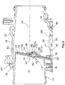
- FIG 1 shows a control device according to a first embodiment.
- the control device according to the invention consists of a housing 10, which delimits an intake duct 12 and in which an opening 14 of an exhaust gas recirculation duct 16 is formed.
- the intake duct 12 runs essentially in a straight direction, while the exhaust gas recirculation duct 16 opens into the intake duct 12 perpendicular to the latter.
- the housing 10 consists of a first, essentially tubular housing part 18. This first housing part 18 is arranged inside a second housing part 22, or is pushed into the second housing part 22 until a flange 24 rests, over which the first housing part 18 is fitted by means of screws 26 is attached to the second housing part 22.
- the second housing part 22 has an opening 28, which is arranged a short distance behind an axial end of the first housing part 18 in the direction of flow and which serves as a receptacle for a third housing part 30, which forms the mouth 14 of the exhaust gas recirculation duct 16, whose central axis 34 is vertical to the central axis 35 of the intake port 12 is arranged.
- a shaft 36 is rotatably arranged in the housing 10 and can be actuated via an actuator that is not visible.
- the axis of rotation 38 of this shaft 36 is arranged perpendicularly to the central axes 34, 35 and is located between the orifice 14 of the exhaust gas recirculation duct 16 downstream of the shaft 36 and the axial end of the first housing part 18 and directly downstream of the first housing part 18.
- the flow cross section of the first housing part 18 is smaller than that of the second housing part 22 of the intake duct 12, the first housing part 18 being fastened to the second housing part 22 in such a way that a recess 40 formed in the region of the mouth of the exhaust gas recirculation duct 16 is outside the flow cross section is arranged, in which the shaft 36, the second housing part 22 is arranged penetrating.
- a control body 42 is fastened to this shaft 36 , which is arranged eccentrically in the intake duct 12 , and consists of a first flap 44 and a second flap 48 fastened to the first flap 44 via a holding pin 46 .
- the first flap 44 extends straight from the shaft 36 and dominates the flow cross section of the intake port 12. To this end, the first flap 44 interacts with the axial end of the first housing part 18, which serves as the intake port valve seat 50, on which the first flap 44 in the state closing the intake port 12, as shown in figure 1 is shown, is present.
- a water-storing coating 58 is arranged on a surface 54 of the first flap 44 facing the exhaust gas recirculation channel 16.
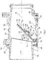
- the water-storing coating 58 thus comes into direct contact with the hot exhaust gas from the exhaust gas recirculation channel 16 in a position of the control body 42 between the first and the second end position. Water from the exhaust gas which is condensed on the cooler first flap 44 is thus temporarily stored in the water-storing coating 58 .
- exhaust gas duct is opened, exhaust gas flows against this flap side and heats up the water-storing coating 58 in such a way that the water stored therein is released from the coating 58 again.
- the holding axle 46 has a plurality of axially consecutive sections of different diameters, of which a first section 66 penetrates the bore 62 and in the rear area is formed to produce a rivet connection and the second, larger portion 70 rests flat against the first flap 44.
- a third axial section 74 has a smaller diameter than the second section 70, followed by a fourth section 78, which again has a reduced diameter.
- the second flap 48 is arranged on this fourth section 78, which has a central opening 82 through which the retaining pin 46 penetrates, the diameter of this opening 82 being slightly larger than the diameter of the fourth section 78, as a result of which the second flap 48 on the Holding axle 46 can be easily tilted.
- a spring 86 also surrounds the fourth section 78 and presses the flap 48 against a spherical shoulder between the third section 74 and the fourth section 78, which serves as a stop 90.
- a washer 94 which is mounted on a fifth section 98, serves as an abutment for this spring 86 of the holding axle 46, where it is fastened by reshaping a following section 102 of the holding axle 46 penetrating the disc 94.
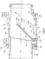
- This fastening of the second flap 48 means that when the shaft 36 is rotated into the second end position, as shown in figure 3 is shown, in which the second flap 48 rests on the opening 14 of the exhaust gas recirculation duct 16 serving as valve seat 106, a complete tight closure of the exhaust gas recirculation duct 16 takes place, since the flap 48 adjusts its position by the possible tilting movement to the position of the valve seat 106 of the exhaust gas recirculation duct 16 can adjust, even if this is not completely parallel to the central axis 35 of the intake port 12 is formed.
- FIG 4 shows a control device according to a second embodiment with the control body 42 in a middle position.
- This control device differs from the control device from the first exemplary embodiment in that the control body 42 has only a single control flap 108 .
- This Regulating valve 108 can close both exhaust gas recirculation channel 16 and intake channel 12 .
- the coating 58 is arranged on a surface 110 of the control valve 108 facing the exhaust gas recirculation channel 16 .
- a contact area 114 of the surface 110 of the control valve 108 which is in contact with the valve seat 106 of the exhaust gas recirculation channel 16 in a second end position, is exempt from the coating 58.
Landscapes
- Engineering & Computer Science (AREA)
- General Engineering & Computer Science (AREA)
- Mechanical Engineering (AREA)
- Chemical & Material Sciences (AREA)
- Combustion & Propulsion (AREA)
- Manufacturing & Machinery (AREA)
- Chemical Kinetics & Catalysis (AREA)
- Lift Valve (AREA)
Description
- Die vorliegende Erfindung betrifft eine Regelvorrichtung für eine Verbrennungskraftmaschine mit einem Ansaugkanal, einem Abgasrückführkanal, der in den Ansaugkanal mündet, einem Gehäuse, in dem der Ansaugkanal und zumindest eine Mündung des Abgasrückführkanals ausgebildet sind, und einer als Drehachse dienenden Welle, die im Gehäuse bezüglich des Luftstroms stromaufwärts der Mündung des Abgasrückführkanals und senkrecht zu den Mittelachsen des Ansaugkanals und des Abgasrückführkanals angeordnet ist. Die Regelvorrichtung umfasst ferner einen Regelkörper, der an der Welle befestigt ist, über die der Regelkörper im Ansaugkanal drehbar ist, wobei der Regelkörper in einer ersten Endstellung den Ansaugkanal zumindest drosselt, und in einer zweiten Endstellung an einem Ventilsitz anliegt, in welcher der Regelkörper den Abgasrückführkanal verschließt.
- Regelvorrichtungen werden in Verbrennungskraftmaschinen genutzt, um Abgas- oder Luftmengen zu regeln, die abgeführt oder der Verbrennung zugeführt werden sollen. Auch Kombinationen dieser Regelventile, bei denen zwei Ventilkörper über eine gemeinsame Stellvorrichtung betätigt werden, sind bekannt. Insbesondere wurden Kombinationen eines Abgasrückführventils mit einer Drosselklappe offenbart. Bei diesen Ausführungen mündet der Abgasrückführkanal unmittelbar stromabwärts der als Drosselventil dienenden Klappe in den Luftansaugkanal. Bei gewünschter Erhöhung der Abgasrückführrate wird dann mit Öffnen des Abgasrückführventils in gleichem Maße die Drosselklappe geschlossen, was eine Erhöhung des Druckgefälles im Abgasrückführkanal zur Folge hat, wodurch der Anteil des Abgases im Vergleich zur angesaugten Luftmenge erhöht wird. Eine derartige Anordnung wird beispielsweise in der
DE 27 03 687 A1 offenbart. - Aus der
DE 20 2014 100 190 U1 ist ebenfalls eine solche Regelvorrichtung bekannt. Die Regelvorrichtung weist eine erste Drosselklappe auf, welche ausgebildet ist, die durch einen Frischlufteinlass einströmende Frischluftmenge zu regeln. An der ersten Drosselklappe ist eine zweite Drosselklappe angeordnet, welche eine aus einem Abgaskanal einströmende Abgasmenge beeinflusst. Die Drosselklappen sind im Gehäuse im geschlossenen Zustand des Abgasrückführkanals derart angeordnet, dass die Klappen außerhalb des Durchströmquerschnitts des Luftkanals in einer Wanne angeordnet sind. Über die Wanne wird anfallendes Kondensat zum Abgaskanal geleitet. Das zum Abgaskanal geleitete Kondensat strömt bei Öffnung des Kanals in den Abgaskanal. Dort wird das Kondensat verdampft und strömt mit dem Abgas als Wasserdampf in den Luftkanal. Eine solche Klappe ist auch aus derEP 3 012 445 A1 bekannt. - Zusätzlich ist aus der
DE 10 2014 222 240 A1 eine einen Strömungskanal beherrschende Klappe bekannt, deren Oberfläche mit einer hydrophilen oder einer hydrophoben Beschichtung versehen werden kann. Während bei der hydrophoben Beschichtung ein Anhaften von Wasser vollständig verhindert werden soll, soll durch die hydrophile Beschichtung ein Abfließen des Wassers von der Klappe sichergestellt werden, um einen Wasserfilm auf der Klappe zu minimieren. - Das an dem Abgaskanal gesammelte Kondensat kann bei einem Neustart des Motors als Eis vorliegen, so dass die zweite Drosselklappe, welche den Abgaskanal verschließt, mit einem Ventilsitz des Abgaskanals festgefroren sein kann. Ein Lösen der zweiten Drosselklappe ist dann erst bei Betriebstemperatur des Motors möglich. Eine Regelung durch die Regelvorrichtung ist somit während der Kaltstartphase nicht möglich.
- Die Aufgabe der vorliegenden Erfindung liegt somit darin, eine Regelvorrichtung zu schaffen, mit welcher eine sichere Funktion der Regelvorrichtung gewährleistet wird und dennoch keine Kondensattropfen in den Verdichter gelangen.
- Diese Aufgabe wird durch eine Regelvorrichtung mit den Merkmalen der Ansprüche 1, 2 und 3 gelöst. Bei der erfindungsgemäßen Regelvorrichtung ist in der zweiten Endstellung des Regelkörpers an einer zum Abgasrückführkanal gewandten Oberfläche des Regelkörpers eine Wasser speichernde Beschichtung angeordnet. Unter einer Wasser speichernden Beschichtung wird gemäß der vorliegenden Erfindung eine Beschichtung verstanden, welche das an der kalten Klappe anfallende Kondensat speichert, so dass keine Tropfen mitgerissen werden können. Die Wasser speichernde Beschichtung speichert das Kondensat bis Abgas mit einer ausreichenden Temperatur anliegt, so dass das Kondensat verdunstet wird. In einer Stellung des Regelkörpers, bei welcher der Abgasrückführkanal geöffnet und der Ansaugkanal gedrosselt wird, kann die Beschichtung durch das Abgas derart erhitzt werden, dass das darin gespeicherte Kondensat verdunstet wird. Dadurch bleibt die Beschichtung weiterhin aufnahmefähig für Kondensat. Ein Mitreißen von Kondensattropfen durch den Strom kann somit auch dauerhaft vermieden werden. Durch das Speichern des Kondensats in der Wasser speichernden Beschichtung wird vermieden, dass sich Kondensat am Ventilsitz des Abgasrückführkanal sammelt. Dadurch friert der Regelkörper nicht fest, so dass eine Regelung auch in einer Kaltstartphase des Motors möglich ist. Der Regelkörper weist in einer erfindungsgemäßen Ausführung (Anspruch 1) eine einzige
- Regelklappe auf, an welcher die Beschichtung angeordnet ist, wobei ein Kontaktbereich der Regelklappe mit dem Ventilsitz des Abgasrückführkanals von der Beschichtung ausgespart ist. Eine einzige Regelklappe hat den Vorteil, dass der Regelkörper sehr wirtschaftlich herstellbar ist. Darüber hinaus sind keine weiteren Elemente des Regelkörpers vorhanden, an denen sich Kondensat bilden könnte, welche nicht mit einer Beschichtung versehen sind.
- Alternativ weist der Regelkörper eine erste Klappe, die den Ansaugkanal verschließt, und eine an der ersten Klappe befestigte zweite Klappe, die den Abgasrückführkanal drosselt, auf. Durch die Ausführung mit zwei Klappen kann die Anordnung der Ventilsitze zueinander mit deutlich ungenaueren Toleranzen erfolgen. Des Weiteren kann der Regelkörper vollständig aus dem durchströmten Bereich des Luftansaugkanals herausgedreht werden. Dabei ist die Beschichtung entweder an der ersten Klappe angeordnet (Anspruch 2), so dass aufgrund des direkten Kontaktes der ersten Klappe mit dem kühlen Luftstrom eine Kondensationsneigung des Abgases an dieser Klappe am größten ist, wodurch sich an dieser Klappe bildende Kondensationstropfen, welche vom Luftstrom mitgerissen werden können, vermieden werden können, oder alternativ ist die Beschichtung an der zweiten Klappe angeordnet (Anspruch 3), wobei ein Kontaktbereich der zweiten Klappe mit dem Ventilsitz des Abgasrückführkanals von der Beschichtung ausgespart ist. Die zweite Klappe ist direkt oberhalb der Mündung des Abgasrückführkanals angeordnet, so dass das heiße Abgas zuerst direkt auf diese Klappe trifft. Das an der zweiten Klappe kondensierende Wasser kann somit in der Beschichtung gespeichert werden. Um in der zweiten Endstellung eine gute Dichtwirkung zwischen Klappe und Ventilsitz des Abgasrückführkanals zu erzielen, ist die Beschichtung in einem Kontaktbereich der zweiten Klappe mit dem Ventilsitz des Abgasrückführkanals ausgespart.
- In einer bevorzugten Ausführungsform der Erfindung ist die Welle außerhalb des Durchströmungsquerschnittes angeordnet. Gemäß der vorliegenden Erfindung ist der Durchströmungsquerschnitt der Querschnitt im Gehäuse, welcher von dem Luftstrom aus dem Ansaugkanal hauptsächlich durchströmt wird. Durch diese Anordnung kann der Luftstrom, insbesondere in einer zweiten Endstellung des Regelkörpers, in welcher der Regelkörper an dem Ventilsitz des Abgasrückführkanal anliegt, ungehindert zum Verdichter strömen.
- In einer weiteren bevorzugten Ausführungsform ist der Regelkörper exzentrisch an der Welle befestigt. Durch eine exzentrische Anordnung des Regelkörpers zur Welle, kann die Welle beabstandet zum Regelkörper angeordnet werden. Dadurch kann die Welle variable zum Regelkörper im Gehäuse positioniert werden. Beispielsweise ist dadurch eine Anordnung möglich, bei welcher die Welle außerhalb des Durchströmungsquerschnittes angeordnet ist.
- Bei einer bevorzugten Ausgestaltung der Erfindung liegt der Regelkörper in der ersten Endstellung, in welcher der Regelkörper den Ansaugkanal verschließt, an einem Ansaugkanal-Ventilsitz an. Dadurch kann eine vollständige Regelung des Luftstromes durchgeführt werden.
- Vorzugsweise ist die Beschichtung aus einem Schaum gebildet. Ein Schaum ist einfach auf eine definierte Oberfläche aufzubringen. Zudem besitzt ein Schaum gute Eigenschaften zur Aufnahme des Kondensats. Der Schaum hat zudem eine isolierende Wirkung zur kalten Seite der Klappe, so dass die Bildung von Kondensat am kalten Klappenkörper vermindert wird. Besonders bevorzugt ist der Schaum, Melaminharzschaum. Dieser Schaum besitzt gute Kondensatspeicherfähigkeiten und ist auch sehr beständig bei einer aggressiven Umgebung, wie es bei einem Abgasrückführventil vorherrscht. Der Melaminharzschaum weist damit auch eine lange Haltbarkeit auf.
- In einer weiteren bevorzugten Ausführungsform ist die Beschichtung an der ersten Klappe und an der zweiten Klappe angeordnet, wobei ein Kontaktbereich der zweiten Klappe mit dem Ventilsitz des Abgasrückführkanals von der Beschichtung ausgespart ist. Dadurch wird jede Klappe, an welcher sich Kondensationstropfen bilden können, mit der Beschichtung versehen. Somit wird die Bildung von Kondensationstropfen nochmals vermindert. Um in der zweiten Endstellung eine gute Dichtwirkung zwischen Klappe und Ventilsitz des Abgasrückführkanals zu erzielen, ist auch hier die Beschichtung in einem Kontaktbereich der zweiten Klappe mit dem Ventilsitz des Abgasrückführkanals ausgespart.
- Die erfindungsgemäße Regelvorrichtung hat somit den Vorteil, dass das Kondensat so lange gespeichert wird, bis eine ausreichende Temperatur zum Verdampfen vorhanden ist, so dass eine Beschädigung des Verdichters vermieden wird.
- Weitere Einzelheiten und Vorteile der vorliegenden Erfindung ergeben sich aus der nachfolgenden Beschreibung der Ausführungsbeispiele in Verbindung mit den Zeichnungen. In diesen zeigen:
- Figur 1:
- Seitenansicht einer erfindungsgemäßen Regelvorrichtung mit einem Regelkörper in einer ersten Endstellung in geschnittener Darstellung,
- Figur 2:
- Seitenansicht der erfindungsgemäßen Regelvorrichtung aus
Figur 1 mit einem Regelkörper in einer Mittelposition in geschnittener Darstellung, - Figur 3:
- Seitenansicht der erfindungsgemäßen Regelvorrichtung aus
Figur 1 mit einem Regelkörper in einer zweiten Endstellung in geschnittener Darstellung, und - Figur 4:
- Seitenansicht der Regelvorrichtung nach einem zweiten Ausführungsbeispiel mit einem Regelkörper in einer Mittelposition in geschnittener Darstellung.
-
Figur 1 zeigt eine Regelvorrichtung nach einem ersten Ausführungsbeispiel. Die erfindungsgemäße Regelvorrichtung besteht aus einem Gehäuse 10, welches einen Ansaugkanal 12 begrenzt und in dem eine Mündung 14 eines Abgasrückführkanals 16 ausgebildet ist. Der Ansaugkanal 12 verläuft im Wesentlichen in gerader Richtung, während der Abgasrückführkanal 16 senkrecht zum Ansaugkanal 12 in diesen mündet. - Das Gehäuse 10 besteht aus einem ersten im Wesentlichen rohrförmig ausgebildeten Gehäuseteil 18. Dieses erste Gehäuseteil 18 ist im Innern eines zweiten Gehäuseteils 22 angeordnet, beziehungsweise wird in das zweite Gehäuseteil 22 bis zur Anlage eines Flansches 24 eingeschoben, über den das erste Gehäuseteil 18 mittels Schrauben 26 am zweiten Gehäuseteil 22 befestigt ist. Das zweite Gehäuseteil 22 weist eine Öffnung 28 auf, welche in Strömungsrichtung in kurzem Abstand hinter einem axialen Ende des ersten Gehäuseteils 18 angeordnet ist und welches als Aufnahme für ein drittes Gehäuseteil 30 dient, welches die Mündung 14 des Abgasrückführkanals 16 bildet, dessen Mittelachse 34 senkrecht zur Mittelachse 35 des Ansaugkanals 12 angeordnet ist.
- Im Gehäuse 10 ist eine Welle 36 drehbar angeordnet, die über einen nicht sichtbaren Aktor betätigt werden kann. Die Drehachse 38 dieser Welle 36 ist senkrecht zu den Mittelachsen 34, 35 angeordnet und befindet sich zwischen der zur Welle 36 stromabwärtigen Mündung 14 des Abgasrückführkanals 16 und dem axialen Ende des ersten Gehäuseteils 18 und unmittelbar stromabwärts des ersten Gehäuseteils 18. Der Durchströmungsquerschnitt des ersten Gehäuseteils 18 ist kleiner als der des zweiten Gehäuseteils 22 des Ansaugkanals 12, wobei das erste Gehäuseteil 18 derart am zweiten Gehäuseteil 22 befestigt ist, dass eine im Bereich der Mündung des Abgasrückführkanals 16 ausgebildete Ausnehmung 40 außerhalb des Durchströmungsquerschnitts angeordnet ist, in der die Welle 36, das zweite Gehäuseteil 22 durchdringend, angeordnet ist.
- An dieser exzentrisch im Ansaugkanal 12 angeordneten Welle 36 ist ein Regelkörper 42 befestigt, der aus einer ersten Klappe 44 sowie einer über eine Halteachse 46 an der ersten Klappe 44 befestigten zweiten Klappe 48 besteht. Die erste Klappe 44 erstreckt sich gerade von der Welle 36 aus und beherrscht den Durchströmungsquerschnitt des Ansaugkanals 12. Hierzu wirkt die erste Klappe 44 mit dem axialen Ende des ersten Gehäuseteils 18 zusammen, das als Ansaugkanal-Ventilsitz 50 dient, auf dem die erste Klappe 44 im den Ansaugkanal 12 verschließenden Zustand, wie er in
Figur 1 dargestellt ist, anliegt. - In einer zweiten Endstellung des Regelkörpers 42 in der die zweite Klappe 48 auf einem Ventilsitz 106 des Abgasrückführkanal 16 aufliegt, ist auf einer zum Abgasrückführkanal 16 gewandte Oberfläche 54 der ersten Klappe 44 eine Wasser speichernde Beschichtung 58 angeordnet. Die Wasser speichernde Beschichtung 58 kommt somit in einer Stellung des Regelkörpers 42 zwischen der ersten und der zweiten Endstellung direkt mit dem heißen Abgas aus dem Abgasrückführkanal 16 in Kontakt. Wasser aus dem Abgas, welches an der kühleren ersten Klappe 44 kondensiert wird somit in der Wasser speichernden Beschichtung 58 zwischengespeichert. Bei Öffnung des Abgaskanals strömt Abgas gegen diese Klappenseite und heizt die Wasser speichernde Beschichtung 58 derart auf, dass das darin gespeicherte Wasser wieder aus der Beschichtung 58 abgegeben wird.
- In der ersten Klappe 44 ist im zentralen Bereich eine Bohrung 62 ausgebildet, in der die Halteachse 46 befestigt ist. Diese erstreckt sich zur zum ersten Gehäuseteil 18 gegenüberliegenden Seite senkrecht zur ersten Klappe 44. Die Halteachse 46 weist mehrere axial hintereinanderliegende Abschnitte unterschiedlicher Durchmesser auf, von denen ein erster Abschnitt 66 die Bohrung 62 durchdringt und im hinteren Bereich zur Erzeugung einer Nietverbindung umgeformt ist und der zweite, größere Abschnitt 70 flächig gegen die erste Klappe 44 anliegt. Ein dritter axialer Abschnitt 74 weist einen kleineren Durchmesser als der zweite Abschnitt 70 auf, gefolgt von einem vierten Abschnitt 78 mit wiederum verkleinertem Durchmesser. Auf diesem vierten Abschnitt 78 ist die zweite Klappe 48 angeordnet, welche eine zentrale Öffnung 82 aufweist, durch die die Halteachse 46 dringt, wobei der Durchmesser dieser Öffnung 82 etwas größer ist als der Durchmesser des vierten Abschnitts 78, wodurch die zweite Klappe 48 auf der Halteachse 46 leicht gekippt werden kann. Eine Feder 86 umgibt ebenfalls den vierten Abschnitt 78 und drückt die Klappe 48 gegen einen als Anschlag 90 dienenden kugeligen Absatz zwischen dem dritten Abschnitt 74 und dem vierten Abschnitt 78. Als Widerlager für diese Feder 86 dient eine Scheibe 94, welche auf einem fünften Abschnitt 98 der Halteachse 46 angeordnet ist, wo sie durch Umformen, eines die Scheibe 94 durchdringenden folgenden Abschnitts 102 der Halteachse 46 befestigt wird. Diese Befestigung der zweiten Klappe 48 führt dazu, dass bei Drehung der Welle 36 in der zweite Endstellung, wie sie in
Figur 3 dargestellt ist, in der die zweite Klappe 48 auf der als Ventilsitz 106 dienenden Mündung 14 des Abgasrückführkanals 16 aufliegt, ein vollständiger dichter Verschluss des Abgasrückführkanals 16 erfolgt, da die Klappe 48 ihre Stellung durch die mögliche Kippbewegung an die Lage des Ventilsitzes 106 des Abgasrückführkanals 16 anpassen kann, auch wenn dieser nicht vollständig parallel zur Mittelachse 35 des Ansaugkanals 12 ausgebildet ist. -
Figur 4 zeigt eine Regelvorrichtung nach einem zweiten Ausführungsbeispiel mit dem Regelkörper 42 in einer Mittelposition. In der folgenden Beschreibung werden für gleichwirkende Teile gleiche Bezugszeichen verwendet. Diese Regelvorrichtung unterscheidet sich von der Regelvorrichtung aus dem ersten Ausführungsbeispiel dadurch, dass der Regelkörper 42 lediglich eine einzige Regelklappe 108 aufweist. Diese Regelklappe 108 kann sowohl den Abgasrückführkanals 16 als auch den Ansaugkanals 12 verschließen. Bei dem zweiten Ausführungsbeispiel ist die Beschichtung 58 auf einer dem Abgasrückführkanals 16 zugewandten Oberfläche 110 der Regelklappe 108 angeordnet. Ein Kontaktbereich 114 der Oberfläche 110 der Regelklappe 108, welcher in einer zweiten Endstellung in Kontakt mit dem Ventilsitz 106 des Abgasrückführkanals 16 ist, ist von der Beschichtung 58 ausgenommen. - Es sollte deutlich sein, dass der Schutzbereich der vorliegenden Anmeldung nicht auf die beschriebenen Ausführungsbeispiele beschränkt ist. Insbesondere sind verschiedene Modifikationen bezüglich des Zusammenbaus und der Ausformung der Gehäuseteile und der beiden Klappen denkbar.
-
- 10
- Gehäuse
- 12
- Ansaugkanal
- 14
- Mündung
- 16
- Abgasrückführkanal
- 18
- erste Gehäuseteil
- 22
- zweite Gehäuseteil
- 24
- Flansch
- 26
- Schrauben
- 28
- Öffnung
- 30
- drittes Gehäuseteil
- 34
- Mittelachse Abgasrückführkanal
- 35
- Mittelachse Ansaugkanal
- 36
- Welle
- 38
- Drehachse
- 40
- Ausnehmung
- 42
- Regelkörper
- 44
- erste Klappe
- 46
- Halteachse
- 48
- zweite Klappe
- 50
- Ansaugkanal-Ventilsitz
- 54
- Oberfläche
- 58
- Beschichtung
- 62
- Bohrung
- 66
- erster Abschnitt
- 70
- zweite Abschnitt
- 74
- dritter Abschnitt
- 78
- vierten Abschnitt
- 82
- zentrale Öffnung
- 86
- Feder
- 90
- Anschlag
- 94
- Scheibe
- 98
- fünfter Abschnitt
- 102
- Abschnitt
- 106
- Ventilsitz
- 108
- Regelklappe
- 110
- Oberfläche
- 114
- Kontaktbereich
Claims (9)
- Regelvorrichtung für eine Verbrennungskraftmaschine mit- einem Ansaugkanal (12),- einem Abgasrückführkanal (16), der in den Ansaugkanal (12) mündet,- einem Gehäuse (10), in dem der Ansaugkanal (12) und zumindest eine Mündung (14) des Abgasrückführkanals (16) ausgebildet sind,- einer als Drehachse (38) dienenden Welle (36), die im Gehäuse (10) bezüglich des Luftstroms stromaufwärts der Mündung (14) des Abgasrückführkanals (16) und senkrecht zu den Mittelachsen (34, 35) des Ansaugkanals (12) und des Abgasrückführkanals (16) angeordnet ist,- einem Regelkörper (42), der an der Welle (36) befestigt ist, über die der Regelkörper (42) im Ansaugkanal (12) drehbar ist, wobei der Regelkörper (42) in einer ersten Endstellung den Ansaugkanal (12) zumindest drosselt, und in einer zweiten Endstellung an einem Ventilsitz (106) anliegt, in welcher der Regelkörper (42) den Abgasrückführkanal (16) verschließt,dadurch gekennzeichnet, dass
in der zweiten Endstellung des Regelkörpers (42) an einer zum Abgasrückführkanal (16) gewandten Oberfläche (54, 110) des Regelkörpers (42) eine Wasser speichernde Beschichtung (58) angeordnet ist und der Regelkörper (42) eine einzige Regelklappe (108) aufweist, an welcher die Beschichtung (58) angeordnet ist, wobei ein Kontaktbereich (114) der Regelklappe (108) mit dem Ventilsitz (106) des Abgasrückführkanals (16) von der Beschichtung (58) ausgespart ist. - Regelvorrichtung für eine Verbrennungskraftmaschine mit- einem Ansaugkanal (12),- einem Abgasrückführkanal (16), der in den Ansaugkanal (12) mündet,- einem Gehäuse (10), in dem der Ansaugkanal (12) und zumindest eine Mündung (14) des Abgasrückführkanals (16) ausgebildet sind,- einer als Drehachse (38) dienenden Welle (36), die im Gehäuse (10) bezüglich des Luftstroms stromaufwärts der Mündung (14) des Abgasrückführkanals (16) und senkrecht zu den Mittelachsen (34, 35) des Ansaugkanals (12) und des Abgasrückführkanals (16) angeordnet ist,- einem Regelkörper (42), der an der Welle (36) befestigt ist, über die der Regelkörper (42) im Ansaugkanal (12) drehbar ist, wobei der Regelkörper (42) in einer ersten Endstellung den Ansaugkanal (12) zumindest drosselt, und in einer zweiten Endstellung an einem Ventilsitz (106) anliegt, in welcher der Regelkörper (42) den Abgasrückführkanal (16) verschließt,dadurch gekennzeichnet, dass
in der zweiten Endstellung des Regelkörpers (42) an einer zum Abgasrückführkanal (16) gewandten Oberfläche (54, 110) des Regelkörpers (42) eine Wasser speichernde Beschichtung (58) angeordnet ist und der Regelkörper (42) eine erste Klappe (44), die den Ansaugkanal (12) drosselt, und eine an der ersten Klappe (44) befestigte zweite Klappe (48), die den Abgasrückführkanal (16) verschließt, aufweist, wobei die Beschichtung (58) an der ersten Klappe (44) angeordnet ist. - Regelvorrichtung für eine Verbrennungskraftmaschine mit- einem Ansaugkanal (12),- einem Abgasrückführkanal (16), der in den Ansaugkanal (12) mündet,- einem Gehäuse (10), in dem der Ansaugkanal (12) und zumindest eine Mündung (14) des Abgasrückführkanals (16) ausgebildet sind,- einer als Drehachse (38) dienenden Welle (36), die im Gehäuse (10) bezüglich des Luftstroms stromaufwärts der Mündung (14) des Abgasrückführkanals (16) und senkrecht zu den Mittelachsen (34, 35) des Ansaugkanals (12) und des Abgasrückführkanals (16) angeordnet ist,- einem Regelkörper (42), der an der Welle (36) befestigt ist, über die der Regelkörper (42) im Ansaugkanal (12) drehbar ist, wobei der Regelkörper (42) in einer ersten Endstellung den Ansaugkanal (12) zumindest drosselt, und in einer zweiten Endstellung an einem Ventilsitz (106) anliegt, in welcher der Regelkörper (42) den Abgasrückführkanal (16) verschließt,dadurch gekennzeichnet, dass
in der zweiten Endstellung des Regelkörpers (42) an einer zum Abgasrückführkanal (16) gewandten Oberfläche (54, 110) des Regelkörpers (42) eine Wasser speichernde Beschichtung (58) angeordnet ist und der Regelkörper (42) eine erste Klappe (44), die den Ansaugkanal (12) drosselt, und eine an der ersten Klappe (44) befestigte zweite Klappe (48), die den Abgasrückführkanal (16) verschließt, aufweist, wobei die Beschichtung (58) an der zweiten Klappe (48) angeordnet ist und ein Kontaktbereich (114) der zweiten Klappe (48) mit dem Ventilsitz (106) des Abgasrückführkanals (16) von der Beschichtung (58) ausgespart ist. - Regelvorrichtung nach einem der vorhergehenden Ansprüche, dadurch gekennzeichnet, dass die Welle (36) außerhalb des Durchströmungsquerschnittes angeordnet ist.
- Regelvorrichtung nach einem der vorhergehenden Ansprüche, dadurch gekennzeichnet, dass der Regelkörper (42) exzentrisch an der Welle (36) befestigt ist.
- Regelvorrichtung nach einem der vorhergehenden Ansprüche, dadurch gekennzeichnet, dass der Regelkörper (42) in der ersten Endstellung, in welcher der Regelkörper (42) den Ansaugkanal (12) verschließt, an einem Ansaugkanal-Ventilsitz (50) anliegt.
- Regelvorrichtung nach einem der vorhergehenden Ansprüche, dadurch gekennzeichnet, dass die Beschichtung (58) aus einem Schaum gebildet ist.
- Regelvorrichtung nach Anspruch 7, dadurch gekennzeichnet, dass der Schaum, Melaminharzschaum ist.
- Regelvorrichtung nach einem der Ansprüche 2, 3 oder 4-8, wenn dieser von 2 oder 3 abhängt, dadurch
gekennzeichnet, dass die Beschichtung (58) an der ersten Klappe (44) und an der zweiten Klappe (48) angeordnet ist, wobei ein Kontaktbereich (114) der zweiten Klappe (48) mit dem Ventilsitz (106) des Abgasrückführkanals (16) von der Beschichtung (58) ausgespart ist.
Applications Claiming Priority (2)
| Application Number | Priority Date | Filing Date | Title |
|---|---|---|---|
| DE102016108389.5A DE102016108389B4 (de) | 2016-05-06 | 2016-05-06 | Regelvorrichtung |
| PCT/EP2017/057412 WO2017190893A1 (de) | 2016-05-06 | 2017-03-29 | Regelvorrichtung |
Publications (2)
| Publication Number | Publication Date |
|---|---|
| EP3452716A1 EP3452716A1 (de) | 2019-03-13 |
| EP3452716B1 true EP3452716B1 (de) | 2022-05-04 |
Family
ID=58455036
Family Applications (1)
| Application Number | Title | Priority Date | Filing Date |
|---|---|---|---|
| EP17714424.3A Active EP3452716B1 (de) | 2016-05-06 | 2017-03-29 | Regelvorrichtung |
Country Status (3)
| Country | Link |
|---|---|
| EP (1) | EP3452716B1 (de) |
| DE (1) | DE102016108389B4 (de) |
| WO (1) | WO2017190893A1 (de) |
Families Citing this family (2)
| Publication number | Priority date | Publication date | Assignee | Title |
|---|---|---|---|---|
| DE102017109062A1 (de) * | 2017-04-27 | 2018-10-31 | Ford-Werke Gmbh | Regelvorrichtung für eine Verbrennungskraftmaschine |
| DE102017130325B4 (de) | 2017-12-18 | 2021-02-25 | Pierburg Gmbh | Regelvorrichtung für eine Verbrennungskraftmaschine |
Family Cites Families (10)
| Publication number | Priority date | Publication date | Assignee | Title |
|---|---|---|---|---|
| GB784503A (en) * | 1953-08-28 | 1957-10-09 | British Celanese | Process for producing an article or surface with a protective covering of thermoplastic material |
| JPS5215930A (en) | 1975-07-25 | 1977-02-05 | Ibbott Jack Kenneth | Carburetor for internal combustion engine |
| DE2703687A1 (de) | 1977-01-29 | 1978-08-03 | Bosch Gmbh Robert | Vorrichtung fuer die steuerung zusaetzlicher gaszufuehrmengen in das saugrohr einer brennkraftmaschine |
| JPH08291870A (ja) * | 1995-04-21 | 1996-11-05 | Tomoe Gijutsu Kenkyusho:Kk | バタフライ弁およびその製造方法 |
| JPH09317414A (ja) | 1996-05-29 | 1997-12-09 | Aisan Ind Co Ltd | 内燃機関用部品及びその製造方法 |
| JPH11236830A (ja) * | 1998-02-20 | 1999-08-31 | Nissan Motor Co Ltd | 樹脂製スロットルチャンバ |
| JP2011074841A (ja) * | 2009-09-30 | 2011-04-14 | Denso Corp | Egr装置 |
| DE202014100190U1 (de) | 2014-01-16 | 2014-02-12 | Ford Global Technologies, Llc | Niederdruck-EGR-Ventil |
| DE102014114968B4 (de) * | 2014-10-15 | 2021-01-21 | Pierburg Gmbh | Regelvorrichtung für eine Verbrennungskraftmaschine |
| DE102014222240A1 (de) * | 2014-10-30 | 2016-05-04 | Continental Automotive Gmbh | Ventilvorrichtung für ein Kraftfahrzeug |
-
2016
- 2016-05-06 DE DE102016108389.5A patent/DE102016108389B4/de not_active Expired - Fee Related
-
2017
- 2017-03-29 WO PCT/EP2017/057412 patent/WO2017190893A1/de not_active Ceased
- 2017-03-29 EP EP17714424.3A patent/EP3452716B1/de active Active
Also Published As
| Publication number | Publication date |
|---|---|
| DE102016108389A1 (de) | 2017-11-09 |
| WO2017190893A1 (de) | 2017-11-09 |
| EP3452716A1 (de) | 2019-03-13 |
| DE102016108389B4 (de) | 2018-03-15 |
Similar Documents
| Publication | Publication Date | Title |
|---|---|---|
| DE102014114968B4 (de) | Regelvorrichtung für eine Verbrennungskraftmaschine | |
| EP2728156B1 (de) | Regelvorrichtung für eine Verbrennungskraftmaschine | |
| DE112017004109B4 (de) | Mit schlitzen versehene schnappventilanordnung für ein auslasssystem und verfahren zur herstellung einer solchen | |
| DE102015121617B4 (de) | Regelvorrichtung für eine Verbrennungskraftmaschine | |
| DE202018104140U1 (de) | Regelvorrichtung für einen Abgasturbolader | |
| DE102016108389B4 (de) | Regelvorrichtung | |
| EP3374623B1 (de) | Einlasssystem für eine verbrennungskraftmaschine | |
| EP3615787B1 (de) | Regelvorrichtung für eine verbrennungskraftmaschine | |
| EP3387245B1 (de) | Regelvorrichtung für eine verbrennungskraftmaschine | |
| EP3320202B1 (de) | Drei-wege-abgasrückführungs-ventilanordnung mit drei fluidöffnungen für eine abgasrückführung | |
| EP3452717B1 (de) | Regelvorrichtung | |
| EP3615786A1 (de) | Regelvorrichtung für eine verbrennungskraftmaschine | |
| DE102015105219A1 (de) | Regelvorrichtung für einen Abgasführungsabschnitt eines Abgasturboladers | |
| DE102014225626B4 (de) | Regelvorrichtung, Saugrohr und Brennkraftmaschine | |
| DE102016214784A1 (de) | Ventileinrichtung einer Brennkraftmaschine | |
| DE102016112403B4 (de) | Regelvorrichtung für eine Verbrennungskraftmaschine und Verfahren zum Betreiben einer solchen | |
| DE102016121705B4 (de) | Regelvorrichtung für eine Verbrennungskraftmaschine | |
| DE102017130325B4 (de) | Regelvorrichtung für eine Verbrennungskraftmaschine | |
| DE102015105222A1 (de) | Regelvorrichtung für einen Abgasführungsabschnitt eines Abgasturboladers |
Legal Events
| Date | Code | Title | Description |
|---|---|---|---|
| STAA | Information on the status of an ep patent application or granted ep patent |
Free format text: STATUS: UNKNOWN |
|
| STAA | Information on the status of an ep patent application or granted ep patent |
Free format text: STATUS: THE INTERNATIONAL PUBLICATION HAS BEEN MADE |
|
| PUAI | Public reference made under article 153(3) epc to a published international application that has entered the european phase |
Free format text: ORIGINAL CODE: 0009012 |
|
| STAA | Information on the status of an ep patent application or granted ep patent |
Free format text: STATUS: REQUEST FOR EXAMINATION WAS MADE |
|
| 17P | Request for examination filed |
Effective date: 20181109 |
|
| AK | Designated contracting states |
Kind code of ref document: A1 Designated state(s): AL AT BE BG CH CY CZ DE DK EE ES FI FR GB GR HR HU IE IS IT LI LT LU LV MC MK MT NL NO PL PT RO RS SE SI SK SM TR |
|
| AX | Request for extension of the european patent |
Extension state: BA ME |
|
| DAV | Request for validation of the european patent (deleted) | ||
| DAX | Request for extension of the european patent (deleted) | ||
| STAA | Information on the status of an ep patent application or granted ep patent |
Free format text: STATUS: EXAMINATION IS IN PROGRESS |
|
| 17Q | First examination report despatched |
Effective date: 20200316 |
|
| GRAP | Despatch of communication of intention to grant a patent |
Free format text: ORIGINAL CODE: EPIDOSNIGR1 |
|
| STAA | Information on the status of an ep patent application or granted ep patent |
Free format text: STATUS: GRANT OF PATENT IS INTENDED |
|
| INTG | Intention to grant announced |
Effective date: 20211129 |
|
| GRAS | Grant fee paid |
Free format text: ORIGINAL CODE: EPIDOSNIGR3 |
|
| GRAA | (expected) grant |
Free format text: ORIGINAL CODE: 0009210 |
|
| STAA | Information on the status of an ep patent application or granted ep patent |
Free format text: STATUS: THE PATENT HAS BEEN GRANTED |
|
| AK | Designated contracting states |
Kind code of ref document: B1 Designated state(s): AL AT BE BG CH CY CZ DE DK EE ES FI FR GB GR HR HU IE IS IT LI LT LU LV MC MK MT NL NO PL PT RO RS SE SI SK SM TR |
|
| REG | Reference to a national code |
Ref country code: GB Ref legal event code: FG4D Free format text: NOT ENGLISH |
|
| REG | Reference to a national code |
Ref country code: CH Ref legal event code: EP |
|
| REG | Reference to a national code |
Ref country code: AT Ref legal event code: REF Ref document number: 1489277 Country of ref document: AT Kind code of ref document: T Effective date: 20220515 |
|
| REG | Reference to a national code |
Ref country code: DE Ref legal event code: R096 Ref document number: 502017013126 Country of ref document: DE |
|
| REG | Reference to a national code |
Ref country code: IE Ref legal event code: FG4D Free format text: LANGUAGE OF EP DOCUMENT: GERMAN |
|
| REG | Reference to a national code |
Ref country code: LT Ref legal event code: MG9D |
|
| REG | Reference to a national code |
Ref country code: NL Ref legal event code: MP Effective date: 20220504 |
|
| PG25 | Lapsed in a contracting state [announced via postgrant information from national office to epo] |
Ref country code: SE Free format text: LAPSE BECAUSE OF FAILURE TO SUBMIT A TRANSLATION OF THE DESCRIPTION OR TO PAY THE FEE WITHIN THE PRESCRIBED TIME-LIMIT Effective date: 20220504 Ref country code: PT Free format text: LAPSE BECAUSE OF FAILURE TO SUBMIT A TRANSLATION OF THE DESCRIPTION OR TO PAY THE FEE WITHIN THE PRESCRIBED TIME-LIMIT Effective date: 20220905 Ref country code: NO Free format text: LAPSE BECAUSE OF FAILURE TO SUBMIT A TRANSLATION OF THE DESCRIPTION OR TO PAY THE FEE WITHIN THE PRESCRIBED TIME-LIMIT Effective date: 20220804 Ref country code: NL Free format text: LAPSE BECAUSE OF FAILURE TO SUBMIT A TRANSLATION OF THE DESCRIPTION OR TO PAY THE FEE WITHIN THE PRESCRIBED TIME-LIMIT Effective date: 20220504 Ref country code: LT Free format text: LAPSE BECAUSE OF FAILURE TO SUBMIT A TRANSLATION OF THE DESCRIPTION OR TO PAY THE FEE WITHIN THE PRESCRIBED TIME-LIMIT Effective date: 20220504 Ref country code: HR Free format text: LAPSE BECAUSE OF FAILURE TO SUBMIT A TRANSLATION OF THE DESCRIPTION OR TO PAY THE FEE WITHIN THE PRESCRIBED TIME-LIMIT Effective date: 20220504 Ref country code: GR Free format text: LAPSE BECAUSE OF FAILURE TO SUBMIT A TRANSLATION OF THE DESCRIPTION OR TO PAY THE FEE WITHIN THE PRESCRIBED TIME-LIMIT Effective date: 20220805 Ref country code: FI Free format text: LAPSE BECAUSE OF FAILURE TO SUBMIT A TRANSLATION OF THE DESCRIPTION OR TO PAY THE FEE WITHIN THE PRESCRIBED TIME-LIMIT Effective date: 20220504 Ref country code: ES Free format text: LAPSE BECAUSE OF FAILURE TO SUBMIT A TRANSLATION OF THE DESCRIPTION OR TO PAY THE FEE WITHIN THE PRESCRIBED TIME-LIMIT Effective date: 20220504 Ref country code: BG Free format text: LAPSE BECAUSE OF FAILURE TO SUBMIT A TRANSLATION OF THE DESCRIPTION OR TO PAY THE FEE WITHIN THE PRESCRIBED TIME-LIMIT Effective date: 20220804 |
|
| PG25 | Lapsed in a contracting state [announced via postgrant information from national office to epo] |
Ref country code: RS Free format text: LAPSE BECAUSE OF FAILURE TO SUBMIT A TRANSLATION OF THE DESCRIPTION OR TO PAY THE FEE WITHIN THE PRESCRIBED TIME-LIMIT Effective date: 20220504 Ref country code: PL Free format text: LAPSE BECAUSE OF FAILURE TO SUBMIT A TRANSLATION OF THE DESCRIPTION OR TO PAY THE FEE WITHIN THE PRESCRIBED TIME-LIMIT Effective date: 20220504 Ref country code: LV Free format text: LAPSE BECAUSE OF FAILURE TO SUBMIT A TRANSLATION OF THE DESCRIPTION OR TO PAY THE FEE WITHIN THE PRESCRIBED TIME-LIMIT Effective date: 20220504 Ref country code: IS Free format text: LAPSE BECAUSE OF FAILURE TO SUBMIT A TRANSLATION OF THE DESCRIPTION OR TO PAY THE FEE WITHIN THE PRESCRIBED TIME-LIMIT Effective date: 20220904 |
|
| PG25 | Lapsed in a contracting state [announced via postgrant information from national office to epo] |
Ref country code: SM Free format text: LAPSE BECAUSE OF FAILURE TO SUBMIT A TRANSLATION OF THE DESCRIPTION OR TO PAY THE FEE WITHIN THE PRESCRIBED TIME-LIMIT Effective date: 20220504 Ref country code: SK Free format text: LAPSE BECAUSE OF FAILURE TO SUBMIT A TRANSLATION OF THE DESCRIPTION OR TO PAY THE FEE WITHIN THE PRESCRIBED TIME-LIMIT Effective date: 20220504 Ref country code: RO Free format text: LAPSE BECAUSE OF FAILURE TO SUBMIT A TRANSLATION OF THE DESCRIPTION OR TO PAY THE FEE WITHIN THE PRESCRIBED TIME-LIMIT Effective date: 20220504 Ref country code: EE Free format text: LAPSE BECAUSE OF FAILURE TO SUBMIT A TRANSLATION OF THE DESCRIPTION OR TO PAY THE FEE WITHIN THE PRESCRIBED TIME-LIMIT Effective date: 20220504 Ref country code: DK Free format text: LAPSE BECAUSE OF FAILURE TO SUBMIT A TRANSLATION OF THE DESCRIPTION OR TO PAY THE FEE WITHIN THE PRESCRIBED TIME-LIMIT Effective date: 20220504 Ref country code: CZ Free format text: LAPSE BECAUSE OF FAILURE TO SUBMIT A TRANSLATION OF THE DESCRIPTION OR TO PAY THE FEE WITHIN THE PRESCRIBED TIME-LIMIT Effective date: 20220504 |
|
| REG | Reference to a national code |
Ref country code: DE Ref legal event code: R097 Ref document number: 502017013126 Country of ref document: DE |
|
| PLBE | No opposition filed within time limit |
Free format text: ORIGINAL CODE: 0009261 |
|
| STAA | Information on the status of an ep patent application or granted ep patent |
Free format text: STATUS: NO OPPOSITION FILED WITHIN TIME LIMIT |
|
| PG25 | Lapsed in a contracting state [announced via postgrant information from national office to epo] |
Ref country code: AL Free format text: LAPSE BECAUSE OF FAILURE TO SUBMIT A TRANSLATION OF THE DESCRIPTION OR TO PAY THE FEE WITHIN THE PRESCRIBED TIME-LIMIT Effective date: 20220504 |
|
| 26N | No opposition filed |
Effective date: 20230207 |
|
| PG25 | Lapsed in a contracting state [announced via postgrant information from national office to epo] |
Ref country code: SI Free format text: LAPSE BECAUSE OF FAILURE TO SUBMIT A TRANSLATION OF THE DESCRIPTION OR TO PAY THE FEE WITHIN THE PRESCRIBED TIME-LIMIT Effective date: 20220504 |
|
| REG | Reference to a national code |
Ref country code: DE Ref legal event code: R119 Ref document number: 502017013126 Country of ref document: DE |
|
| PG25 | Lapsed in a contracting state [announced via postgrant information from national office to epo] |
Ref country code: MC Free format text: LAPSE BECAUSE OF FAILURE TO SUBMIT A TRANSLATION OF THE DESCRIPTION OR TO PAY THE FEE WITHIN THE PRESCRIBED TIME-LIMIT Effective date: 20220504 |
|
| REG | Reference to a national code |
Ref country code: CH Ref legal event code: PL |
|
| REG | Reference to a national code |
Ref country code: BE Ref legal event code: MM Effective date: 20230331 |
|
| PG25 | Lapsed in a contracting state [announced via postgrant information from national office to epo] |
Ref country code: LU Free format text: LAPSE BECAUSE OF NON-PAYMENT OF DUE FEES Effective date: 20230329 |
|
| REG | Reference to a national code |
Ref country code: IE Ref legal event code: MM4A |
|
| PG25 | Lapsed in a contracting state [announced via postgrant information from national office to epo] |
Ref country code: LI Free format text: LAPSE BECAUSE OF NON-PAYMENT OF DUE FEES Effective date: 20230331 Ref country code: IT Free format text: LAPSE BECAUSE OF FAILURE TO SUBMIT A TRANSLATION OF THE DESCRIPTION OR TO PAY THE FEE WITHIN THE PRESCRIBED TIME-LIMIT Effective date: 20220504 Ref country code: IE Free format text: LAPSE BECAUSE OF NON-PAYMENT OF DUE FEES Effective date: 20230329 Ref country code: DE Free format text: LAPSE BECAUSE OF NON-PAYMENT OF DUE FEES Effective date: 20231003 Ref country code: CH Free format text: LAPSE BECAUSE OF NON-PAYMENT OF DUE FEES Effective date: 20230331 |
|
| PG25 | Lapsed in a contracting state [announced via postgrant information from national office to epo] |
Ref country code: BE Free format text: LAPSE BECAUSE OF NON-PAYMENT OF DUE FEES Effective date: 20230331 |
|
| PGFP | Annual fee paid to national office [announced via postgrant information from national office to epo] |
Ref country code: GB Payment date: 20240322 Year of fee payment: 8 |
|
| REG | Reference to a national code |
Ref country code: AT Ref legal event code: MM01 Ref document number: 1489277 Country of ref document: AT Kind code of ref document: T Effective date: 20230329 |
|
| PGFP | Annual fee paid to national office [announced via postgrant information from national office to epo] |
Ref country code: FR Payment date: 20240319 Year of fee payment: 8 |
|
| PG25 | Lapsed in a contracting state [announced via postgrant information from national office to epo] |
Ref country code: AT Free format text: LAPSE BECAUSE OF NON-PAYMENT OF DUE FEES Effective date: 20230329 |
|
| PG25 | Lapsed in a contracting state [announced via postgrant information from national office to epo] |
Ref country code: AT Free format text: LAPSE BECAUSE OF NON-PAYMENT OF DUE FEES Effective date: 20230329 |
|
| PG25 | Lapsed in a contracting state [announced via postgrant information from national office to epo] |
Ref country code: BG Free format text: LAPSE BECAUSE OF FAILURE TO SUBMIT A TRANSLATION OF THE DESCRIPTION OR TO PAY THE FEE WITHIN THE PRESCRIBED TIME-LIMIT Effective date: 20220504 |
|
| PG25 | Lapsed in a contracting state [announced via postgrant information from national office to epo] |
Ref country code: BG Free format text: LAPSE BECAUSE OF FAILURE TO SUBMIT A TRANSLATION OF THE DESCRIPTION OR TO PAY THE FEE WITHIN THE PRESCRIBED TIME-LIMIT Effective date: 20220504 |
|
| PG25 | Lapsed in a contracting state [announced via postgrant information from national office to epo] |
Ref country code: CY Free format text: LAPSE BECAUSE OF FAILURE TO SUBMIT A TRANSLATION OF THE DESCRIPTION OR TO PAY THE FEE WITHIN THE PRESCRIBED TIME-LIMIT; INVALID AB INITIO Effective date: 20170329 |
|
| PG25 | Lapsed in a contracting state [announced via postgrant information from national office to epo] |
Ref country code: HU Free format text: LAPSE BECAUSE OF FAILURE TO SUBMIT A TRANSLATION OF THE DESCRIPTION OR TO PAY THE FEE WITHIN THE PRESCRIBED TIME-LIMIT; INVALID AB INITIO Effective date: 20170329 |
|
| GBPC | Gb: european patent ceased through non-payment of renewal fee |
Effective date: 20250329 |
|
| PG25 | Lapsed in a contracting state [announced via postgrant information from national office to epo] |
Ref country code: TR Free format text: LAPSE BECAUSE OF FAILURE TO SUBMIT A TRANSLATION OF THE DESCRIPTION OR TO PAY THE FEE WITHIN THE PRESCRIBED TIME-LIMIT Effective date: 20220504 |
|
| PG25 | Lapsed in a contracting state [announced via postgrant information from national office to epo] |
Ref country code: GB Free format text: LAPSE BECAUSE OF NON-PAYMENT OF DUE FEES Effective date: 20250329 |
|
| PG25 | Lapsed in a contracting state [announced via postgrant information from national office to epo] |
Ref country code: FR Free format text: LAPSE BECAUSE OF NON-PAYMENT OF DUE FEES Effective date: 20250331 |