EP3452221B1 - Mikrofluidische neutrophilentests und systeme zur erkennung von erkrankungen - Google Patents
Mikrofluidische neutrophilentests und systeme zur erkennung von erkrankungen Download PDFInfo
- Publication number
- EP3452221B1 EP3452221B1 EP17793545.9A EP17793545A EP3452221B1 EP 3452221 B1 EP3452221 B1 EP 3452221B1 EP 17793545 A EP17793545 A EP 17793545A EP 3452221 B1 EP3452221 B1 EP 3452221B1
- Authority
- EP
- European Patent Office
- Prior art keywords
- migration
- neutrophils
- sepsis
- channels
- chamber
- Prior art date
- Legal status (The legal status is an assumption and is not a legal conclusion. Google has not performed a legal analysis and makes no representation as to the accuracy of the status listed.)
- Active
Links
Images


Classifications
-
- B—PERFORMING OPERATIONS; TRANSPORTING
- B01—PHYSICAL OR CHEMICAL PROCESSES OR APPARATUS IN GENERAL
- B01L—CHEMICAL OR PHYSICAL LABORATORY APPARATUS FOR GENERAL USE
- B01L3/00—Containers or dishes for laboratory use, e.g. laboratory glassware; Droppers
- B01L3/50—Containers for the purpose of retaining a material to be analysed, e.g. test tubes
- B01L3/502—Containers for the purpose of retaining a material to be analysed, e.g. test tubes with fluid transport, e.g. in multi-compartment structures
- B01L3/5027—Containers for the purpose of retaining a material to be analysed, e.g. test tubes with fluid transport, e.g. in multi-compartment structures by integrated microfluidic structures, i.e. dimensions of channels and chambers are such that surface tension forces are important, e.g. lab-on-a-chip
- B01L3/502753—Containers for the purpose of retaining a material to be analysed, e.g. test tubes with fluid transport, e.g. in multi-compartment structures by integrated microfluidic structures, i.e. dimensions of channels and chambers are such that surface tension forces are important, e.g. lab-on-a-chip characterised by bulk separation arrangements on lab-on-a-chip devices, e.g. for filtration or centrifugation
-
- G—PHYSICS
- G01—MEASURING; TESTING
- G01N—INVESTIGATING OR ANALYSING MATERIALS BY DETERMINING THEIR CHEMICAL OR PHYSICAL PROPERTIES
- G01N15/00—Investigating characteristics of particles; Investigating permeability, pore-volume or surface-area of porous materials
- G01N15/02—Investigating particle size or size distribution
- G01N15/0205—Investigating particle size or size distribution by optical means
-
- G—PHYSICS
- G01—MEASURING; TESTING
- G01N—INVESTIGATING OR ANALYSING MATERIALS BY DETERMINING THEIR CHEMICAL OR PHYSICAL PROPERTIES
- G01N15/00—Investigating characteristics of particles; Investigating permeability, pore-volume or surface-area of porous materials
- G01N15/10—Investigating individual particles
- G01N15/1023—Microstructural devices for non-optical measurement
-
- G—PHYSICS
- G01—MEASURING; TESTING
- G01N—INVESTIGATING OR ANALYSING MATERIALS BY DETERMINING THEIR CHEMICAL OR PHYSICAL PROPERTIES
- G01N15/00—Investigating characteristics of particles; Investigating permeability, pore-volume or surface-area of porous materials
- G01N15/10—Investigating individual particles
- G01N15/1031—Investigating individual particles by measuring electrical or magnetic effects
-
- G—PHYSICS
- G01—MEASURING; TESTING
- G01N—INVESTIGATING OR ANALYSING MATERIALS BY DETERMINING THEIR CHEMICAL OR PHYSICAL PROPERTIES
- G01N15/00—Investigating characteristics of particles; Investigating permeability, pore-volume or surface-area of porous materials
- G01N15/10—Investigating individual particles
- G01N15/14—Optical investigation techniques, e.g. flow cytometry
- G01N15/1429—Signal processing
- G01N15/1433—Signal processing using image recognition
-
- G—PHYSICS
- G01—MEASURING; TESTING
- G01N—INVESTIGATING OR ANALYSING MATERIALS BY DETERMINING THEIR CHEMICAL OR PHYSICAL PROPERTIES
- G01N15/00—Investigating characteristics of particles; Investigating permeability, pore-volume or surface-area of porous materials
- G01N15/10—Investigating individual particles
- G01N15/14—Optical investigation techniques, e.g. flow cytometry
- G01N15/1456—Optical investigation techniques, e.g. flow cytometry without spatial resolution of the texture or inner structure of the particle, e.g. processing of pulse signals
- G01N15/1459—Optical investigation techniques, e.g. flow cytometry without spatial resolution of the texture or inner structure of the particle, e.g. processing of pulse signals the analysis being performed on a sample stream
-
- G—PHYSICS
- G01—MEASURING; TESTING
- G01N—INVESTIGATING OR ANALYSING MATERIALS BY DETERMINING THEIR CHEMICAL OR PHYSICAL PROPERTIES
- G01N15/00—Investigating characteristics of particles; Investigating permeability, pore-volume or surface-area of porous materials
- G01N15/10—Investigating individual particles
- G01N15/14—Optical investigation techniques, e.g. flow cytometry
- G01N15/1484—Optical investigation techniques, e.g. flow cytometry microstructural devices
-
- G—PHYSICS
- G01—MEASURING; TESTING
- G01N—INVESTIGATING OR ANALYSING MATERIALS BY DETERMINING THEIR CHEMICAL OR PHYSICAL PROPERTIES
- G01N33/00—Investigating or analysing materials by specific methods not covered by groups G01N1/00 - G01N31/00
- G01N33/48—Biological material, e.g. blood, urine; Haemocytometers
- G01N33/483—Physical analysis of biological material
- G01N33/487—Physical analysis of biological material of liquid biological material
-
- G—PHYSICS
- G01—MEASURING; TESTING
- G01N—INVESTIGATING OR ANALYSING MATERIALS BY DETERMINING THEIR CHEMICAL OR PHYSICAL PROPERTIES
- G01N33/00—Investigating or analysing materials by specific methods not covered by groups G01N1/00 - G01N31/00
- G01N33/48—Biological material, e.g. blood, urine; Haemocytometers
- G01N33/50—Chemical analysis of biological material, e.g. blood, urine; Testing involving biospecific ligand binding methods; Immunological testing
- G01N33/5005—Chemical analysis of biological material, e.g. blood, urine; Testing involving biospecific ligand binding methods; Immunological testing involving human or animal cells
- G01N33/5091—Chemical analysis of biological material, e.g. blood, urine; Testing involving biospecific ligand binding methods; Immunological testing involving human or animal cells for testing the pathological state of an organism
-
- G—PHYSICS
- G01—MEASURING; TESTING
- G01N—INVESTIGATING OR ANALYSING MATERIALS BY DETERMINING THEIR CHEMICAL OR PHYSICAL PROPERTIES
- G01N33/00—Investigating or analysing materials by specific methods not covered by groups G01N1/00 - G01N31/00
- G01N33/48—Biological material, e.g. blood, urine; Haemocytometers
- G01N33/50—Chemical analysis of biological material, e.g. blood, urine; Testing involving biospecific ligand binding methods; Immunological testing
- G01N33/53—Immunoassay; Biospecific binding assay; Materials therefor
- G01N33/543—Immunoassay; Biospecific binding assay; Materials therefor with an insoluble carrier for immobilising immunochemicals
- G01N33/54366—Apparatus specially adapted for solid-phase testing
-
- B—PERFORMING OPERATIONS; TRANSPORTING
- B01—PHYSICAL OR CHEMICAL PROCESSES OR APPARATUS IN GENERAL
- B01L—CHEMICAL OR PHYSICAL LABORATORY APPARATUS FOR GENERAL USE
- B01L2200/00—Solutions for specific problems relating to chemical or physical laboratory apparatus
- B01L2200/06—Fluid handling related problems
- B01L2200/0694—Creating chemical gradients in a fluid
-
- B—PERFORMING OPERATIONS; TRANSPORTING
- B01—PHYSICAL OR CHEMICAL PROCESSES OR APPARATUS IN GENERAL
- B01L—CHEMICAL OR PHYSICAL LABORATORY APPARATUS FOR GENERAL USE
- B01L2300/00—Additional constructional details
- B01L2300/08—Geometry, shape and general structure
- B01L2300/0861—Configuration of multiple channels and/or chambers in a single devices
- B01L2300/0864—Configuration of multiple channels and/or chambers in a single devices comprising only one inlet and multiple receiving wells, e.g. for separation, splitting
-
- B—PERFORMING OPERATIONS; TRANSPORTING
- B01—PHYSICAL OR CHEMICAL PROCESSES OR APPARATUS IN GENERAL
- B01L—CHEMICAL OR PHYSICAL LABORATORY APPARATUS FOR GENERAL USE
- B01L2300/00—Additional constructional details
- B01L2300/08—Geometry, shape and general structure
- B01L2300/0861—Configuration of multiple channels and/or chambers in a single devices
- B01L2300/0867—Multiple inlets and one sample wells, e.g. mixing, dilution
-
- B—PERFORMING OPERATIONS; TRANSPORTING
- B01—PHYSICAL OR CHEMICAL PROCESSES OR APPARATUS IN GENERAL
- B01L—CHEMICAL OR PHYSICAL LABORATORY APPARATUS FOR GENERAL USE
- B01L2400/00—Moving or stopping fluids
- B01L2400/08—Regulating or influencing the flow resistance
- B01L2400/084—Passive control of flow resistance
- B01L2400/086—Passive control of flow resistance using baffles or other fixed flow obstructions
-
- G—PHYSICS
- G01—MEASURING; TESTING
- G01N—INVESTIGATING OR ANALYSING MATERIALS BY DETERMINING THEIR CHEMICAL OR PHYSICAL PROPERTIES
- G01N15/00—Investigating characteristics of particles; Investigating permeability, pore-volume or surface-area of porous materials
- G01N15/10—Investigating individual particles
- G01N2015/1006—Investigating individual particles for cytology
-
- G—PHYSICS
- G01—MEASURING; TESTING
- G01N—INVESTIGATING OR ANALYSING MATERIALS BY DETERMINING THEIR CHEMICAL OR PHYSICAL PROPERTIES
- G01N15/00—Investigating characteristics of particles; Investigating permeability, pore-volume or surface-area of porous materials
- G01N15/10—Investigating individual particles
- G01N2015/1027—Determining speed or velocity of a particle
-
- G—PHYSICS
- G01—MEASURING; TESTING
- G01N—INVESTIGATING OR ANALYSING MATERIALS BY DETERMINING THEIR CHEMICAL OR PHYSICAL PROPERTIES
- G01N15/00—Investigating characteristics of particles; Investigating permeability, pore-volume or surface-area of porous materials
- G01N15/10—Investigating individual particles
- G01N15/14—Optical investigation techniques, e.g. flow cytometry
- G01N2015/1488—Methods for deciding
-
- G—PHYSICS
- G01—MEASURING; TESTING
- G01N—INVESTIGATING OR ANALYSING MATERIALS BY DETERMINING THEIR CHEMICAL OR PHYSICAL PROPERTIES
- G01N15/00—Investigating characteristics of particles; Investigating permeability, pore-volume or surface-area of porous materials
- G01N15/10—Investigating individual particles
- G01N15/14—Optical investigation techniques, e.g. flow cytometry
- G01N2015/1493—Particle size
-
- G—PHYSICS
- G01—MEASURING; TESTING
- G01N—INVESTIGATING OR ANALYSING MATERIALS BY DETERMINING THEIR CHEMICAL OR PHYSICAL PROPERTIES
- G01N2800/00—Detection or diagnosis of diseases
- G01N2800/26—Infectious diseases, e.g. generalised sepsis
Definitions
- This invention relates to the detection of sepsis from whole blood samples.
- Sepsis is caused by the body's response to infection which, can lead to tissue damage, organ failure, and death. Sepsis can be difficult to diagnose and treat using current standards. As a result, sepsis is misdiagnosed in approximately 30% of patients, and is often treated after severe clinical symptoms have appeared. Microbiological cultures can help diagnose sepsis, but require two to three days to grow the bacterial cultures, thereby delaying treatment. Numerous biomarkers have been proposed for diagnosing sepsis, but no biomarkers are in clinical use at this time due to uncertainty about their specificity. Current epidemiological studies of sepsis recommend the use of classifications of end-organ-injury, such as the sequential organ failure assessment (SOFA) or quick SOFA (qSOFA) score, to diagnose sepsis.
- SOFA sequential organ failure assessment
- qSOFA quick SOFA
- Bashar Hamza et al. describe in Lab on a Chip, vol. 15, no. 12, 8 May 2015 on pages 2626-2633 whole blood human neutrophil trafficking in a microfluidic model of infection and inflammation.
- US 2012/094325 A1 describes assays and methods for detecting motile cells, and identifying chemical agents that inhibit cell migration, including detecting the movement of motile cancer cells through a microcapillary channel.
- the methods and microfluidic devices disclosed herein enable the investigation of cell motility in blood samples.
- the methods and devices provide a platform for monitoring the directionality, velocity, and migration persistence of neutrophils in the absence of an exogenous, i.e., externally added, chemical gradient, e.g., an added chemical attractant (e.g., chemoattractant), for the purposes of detecting and quantifying abnormal neutrophil motility phenotypes, using low sample volumes and with minimal, if any, activation of the neutrophils.
- This platform can be used to diagnose a particular disease or ailment in a subject, such as sepsis or Systemic Inflammatory Response Syndrome (SIRS) or SIRS-like disorders, or predict whether a subject is more likely to develop the particular disease or ailment.
- the devices and methods described herein provide the ability to analyze intrinsic neutrophil motility changes in the presence of factors in the blood, e.g., blood plasma, to enable highly specific and sensitive diagnosis of sepsis by quantifying particular neutrophil motility patterns directly in the blood of subjects that are suspected of having sepsis or developing sepsis, e.g., hospital patients who have or are at risk of developing an infection.
- the present methods represent a significant performance improvement compared to current sepsis diagnostic capabilities.
- the devices and methods disclosed herein can be used to monitor the efficacy of sepsis treatment by assaying blood samples from a sepsis patient undergoing treatment over a period of time to quantify changes in neutrophil motility behavior, e.g., to determine whether neutrophils begin exhibiting a motility phenotype more similar to neutrophils form a healthy subject.
- the devices and methods disclosed herein can be used to screen compounds for their potential uses as sepsis treatments, e.g., as new antibiotics or inflammation mediators.
- the new devices can use a baffle filter and/or the size of migration channels to inhibit the movement of undesired cells from a whole blood sample applied directly to the device to a greater extent than the movement of desired motile cells such as neutrophils into the device.
- the neutrophils then intrinsically migrate over time from the sample and through the migration channels. The migration behaviors of the neutrophils can then be monitored in the migration channels and in the migration chamber of the device using time-lapse microscopy.
- microfluidic devices that include a sample loading chamber with a plurality of outlets, a migration chamber having a plurality of inlets and configured and sized to provide motile cells a choice of directional migration, and a plurality of migration channels arranged in fluid communication between the one or more outlets of the sample loading chamber and the one or more inlets of the migration chamber, wherein each migration channel is connected to enable a sample to flow from an outlet of the sample loading chamber to an inlet of the migration chamber.
- the migration channels e.g., inlet ends of the migrations channels, are sized to allow the migration of neutrophils.
- the inlet ends of the migration channels can be sized to exclude red blood cells from entering the channels to a greater extent than neutrophils.
- the microfluidic devices further include, e.g., are filled with, a buffer liquid that includes no exogenous chemical attractant.
- the microfluidic devices further include a baffle arranged in fluid communication between the one or more outlets of the sample loading chamber and the one or more migration channels or within the one or more migration channels, but at a point before each migration channel enters an inlet of the migration chamber.
- the baffle has one or more passageways configured to inhibit the movement of red blood cells through the baffle to a greater extent than the baffle inhibits movement of the neutrophils through the baffle.
- the cross-sectional area of the baffle passageway normal to the sample transport path in the baffle passageway can be less than a red blood cell cross-sectional area, and wherein a width of the cross-sectional area is less than a red blood cell diameter.
- the microfluidic device can further include an exit channel in fluid communication with the migration channel at a point beyond the baffle and before the migration channel enters the inlet of the migration chamber.
- the cross-sectional area of the migration channels or baffle passageways is greater than a red blood cell cross-sectional area, and wherein one or more migration channels or baffle passageways have at least one turn, such that red blood cells are prevented from moving past the turn.
- the microfluidic devices include a plurality of baffle passageways, and a plurality of migration channels; wherein each baffle passageway is in fluid communication with a migration channel, and wherein the migration channels and the migration chamber each comprise a transparent cover material to enable motility of neutrophils to be monitored in the migration channels and the migration chamber.
- the microfluidic device can include a substrate, and the chambers and channels of the device are arranged in fluid communication on the substrate.
- the subject matter of the disclosure is embodied in methods of monitoring the motility of blood cells, e.g., neutrophils, in a microfluidic device, for example, in a microfluidic device as described herein.
- the methods include adding a blood sample to a sample loading chamber of a microfluidic device that include one or more migration channels that each have a first end sized to permit neutrophils to enter the migration channels, wherein the microfluidic device is filled, e.g., primed, with a buffer liquid that includes no exogenous chemical attractant; and monitoring spontaneous motility of one or more neutrophils in the one or more migration channels in the absence of an exogenously added chemical attractant gradient.
- a pattern of spontaneous motility of the one or more neutrophils in the blood sample that is different from a pattern of spontaneous motility of one or more neutrophils in a blood sample from a healthy person indicates that the blood sample is from a subject who has sepsis.
- the devices can include a sample loading chamber with an outlet; a migration chamber having an inlet and configured to enable motile cells a choice of directional migration; and one or more migration channels arranged in fluid communication between the one or more outlets of the sample loading chamber and the one or more inlets of the migration chamber.
- the methods further include adding a blood sample to the sample loading chamber; incubating the device under conditions and for a time sufficient to enable movement of cells in the sample from the sample loading chamber into the one or more migration channels; and monitoring motility of neutrophils in the one or more migration channels and the migration chamber.
- the motility of neutrophils can be monitored by quantifying one or more of the velocity, migration distance, migration direction, velocity persistence, and directional persistence of neutrophils in the one or more migration channels. In some cases, the motility of neutrophils can be monitored by determining the number of spontaneously migrating neutrophils.
- the motility of neutrophils can be monitored by quantifying two or more of the following neutrophil motility parameters: the number of spontaneously migrating neutrophils (N); the number of neutrophils that undergo a migratory oscillation (O); the number of neutrophils that undergo a migratory pause (P); whether neutrophils reverse their migration (R); the average distance migrated by neutrophils (AD); the maximum migration distance (MD); the mean velocity of neutrophils (V); the mean acceleration of neutrophils (A); the mean distance of oscillatory migration (OD); the mean forward migration of neutrophils away from the migration chamber entrance, e.g., a maze chamber (F); the mean vertical migration of neutrophils parallel to the migration channels (VM); the mean horizontal migration of neutrophils perpendicular to the migration channels (HM); and the mean nucleus size of migrating neutrophils (S).
- N spontaneously migrating neutrophils
- O the number of neutrophils that undergo a migratory oscillation
- P the number of
- the motility of neutrophils can be monitored by quantifying the following neutrophil motility parameters: the number of spontaneously migrating neutrophils (N); the number of neutrophils that undergo a migratory oscillation (O); the number of neutrophils that undergo a migratory pause (P); whether neutrophils reverse their migration (R); and the average distance migrated by neutrophils (AD).
- N the number of spontaneously migrating neutrophils
- O the number of neutrophils that undergo a migratory oscillation
- P the number of neutrophils that undergo a migratory pause
- R whether neutrophils reverse their migration
- AD average distance migrated by neutrophils
- a sepsis score can be determined by combining the quantified results for the neutrophil motility parameters; and wherein a sepsis score that is above a certain threshold indicates that the subject has sepsis or will develop sepsis.
- a sepsis score of 30 and above indicates that the subject has sepsis or will develop sepsis
- the blood sample to be used for testing in the microfluidic device is collected from a human or animal subject, e.g., a mammal, e.g., a laboratory or domesticated mammal such as a monkey, dog, cat, rabbit, horse, cow, sheep, or goat.
- a mammal e.g., a laboratory or domesticated mammal such as a monkey, dog, cat, rabbit, horse, cow, sheep, or goat.
- the motility of neutrophils can be monitored by quantifying the number of spontaneously migrating neutrophils; the number of neutrophils that undergo a migratory oscillation; the number of neutrophils that undergo a migratory pause; whether neutrophils reverse their migration; and the average distance migrated by neutrophils.
- motility means the ability of a motile cell to move itself, e.g., at a specific migration rate.
- Motile cells include neutrophils.
- spontaneous neutrophil migration or “spontaneous neutrophil motility” refers to the particular migration characteristics of neutrophils in the absence of a chemical attractant gradient, e.g., from a subject who has sepsis.
- Neutrophils in the blood of subjects with sepsis exhibit dysregulated migration relative to the neutrophils present in the blood of subjects without sepsis, e.g., healthy subjects or hospital patients without sepsis.
- Particular migration patterns or behaviors are observed in spontaneous neutrophil migration that alone, or in combination, are indicative of sepsis. For example, greater numbers of spontaneously migrating cells, increased oscillation during migration, pausing during migration, reverse migration, and increased average migration distances are indicative of sepsis are all parameters that can be used to diagnose sepsis.
- the methods and devices disclosed herein provide microfluidic devices that can be used to investigate cell motility in blood samples for the purposes of detecting and quantifying abnormal motility phenotypes to determine the extent of damage to motile cells. Such information can be used to diagnose a particular disease or ailment, such as sepsis or Systemic Inflammatory Response Syndrome (SIRS) or SIRS-like disorders, or predict whether a patient is more likely to develop the particular disease or ailment.
- the devices disclosed herein provide a platform for diagnosing sepsis by analyzing the directional migration, velocity, and other migratory behaviors of neutrophils from the blood samples of patients with injuries that put them at high risk of having or developing sepsis.
- the methods and devices disclosed herein provide new microfluidic devices that can be used to investigate cell motility, such as the motility of neutrophils in blood samples.
- the microfluidic devices can be used to monitor and measure the directional migration, speed, and other migratory behaviors of neutrophils in the absence of a chemical gradient, e.g., an added chemical gradient such as a chemoattractant, using low sample volumes and with minimal, if any, activation of the neutrophils.
- the methods can be used to measure and analyze the condition of cell motility of neutrophils in a subject that has suffered from an injury, trauma, or infection, so as to accurately determine whether the subject has sepsis.
- the methods can be used to monitor spontaneous neutrophil motility in a blood sample, e.g., a whole blood sample, of a subject suspected of having sepsis, thereby enabling the diagnosis of sepsis in the subj ect.
- a blood sample e.g., a whole blood sample
- the methods disclosed herein enable the measurement of patterns of neutrophil spontaneous motility in the microfluidic device directly from a droplet of blood, thereby preserving the physiological and biochemical environment of the neutrophils.
- Neutrophils are sensitive to circulating factors and integrate these signals to modulate their activation state and behavior. Neutrophil activation during sepsis is likely the cumulative effect of inflammation- and infection-related factors present in the circulation. Measuring neutrophil behavior directly from whole blood samples can amplify sepsis-specific behavioral changes in motility.
- whole blood in the assay preserves the distinct neutrophil motility patterns that differentiate sepsis patients from subjects without sepsis. These distinct, sepsis-specific motility patterns would otherwise be compromised if the neutrophils were first isolated from the blood and then applied to the device in the absence of plasma factors.
- Blood can be collected from a venous source or by a finger prick from a subject using standard methods.
- venous blood is collected into Heparin-coated vacuum tubes.
- a small volume of the blood (100-500 ⁇ l) is then diluted 1:1 in a buffer, such as Iscove's Modified Dulbecco's Medium (IMDM) + 20% FBS, and stained with a stain that to facilitate tracking of the cells, e.g., Hoechst stain, e.g., for a sufficient time, e.g., 15 minutes, prior to loading the diluted blood into the sample loading chamber of the device.
- IMDM Iscove's Modified Dulbecco's Medium
- the sample area of a subject's finger from which blood is to be drawn is wiped thoroughly with an alcohol wipe and allowed to dry.
- a pressure-activated spring-loaded pricking device is then applied to the finger until activated.
- a droplet of blood will begin to form at the site, which is removed with a gauze wipe.
- a 20-50 ⁇ l sample is taken from the second droplet of blood and diluted, e.g., 1:1 in IMDM + 20% FBS. This sample is then stained with Hoechst for at least 15 minutes prior to loading into the sample loading chamber of the device. Regardless of how the blood is collected, the blood should be tested within the first 3 hours after collection, because neutrophil activity declines as the blood ages.
- microfluidic devices disclosed herein are designed to have channels and mazes that enable direct observation of the motility patterns of neutrophils that migrate into the device from whole blood samples applied to the device, e.g., blood samples collected from healthy donors or subjects with sepsis.
- assays using the devices disclosed herein enable higher precision measurements of neutrophil motility by incorporating narrow, branching microfluidic channels and mazes. This enables more precise identification and measurement of particular neutrophil motility patterns compared to straight microfluidic channels or more traditional cell migration assays that do not incorporate microfluidic channels, e.g., migration assays that allow cells to migrate over relatively larger surfaces such that it is difficult to measure and categorize the small, continuous directional changes made by the cells. Confining moving neutrophils to channels and mazes enables motility measurements that are less sensitive to signal noise.
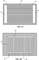
- FIG. 1A is a schematic of an example of a microfluidic device disclosed herein that can be used to monitor cell motility.
- the device integrates a sample loading chamber 15 into which a small volume of blood may be loaded, e.g., ⁇ 1 to 5 ⁇ L, a migration chamber 26, and a series of migration channels 20, each having an inlet 22 and an outlet 24, which are in fluid communication with the sample loading chamber 15 via their inlets 22 and with the migration chamber 26 via their outlets.
- These migration channels are used to detect and measure the directional choices, velocity, and migration persistence of motile cells.
- FIG. 1B is a schematic of another microfluidic device disclosed here that can be used to monitor cell motility.
- the device includes a sample loading chamber 50 into which a small volume of blood may be loaded, a migration channel 80, at least one migration channel 60, and at least one baffle passageway 70 that is in fluid communication with the sample loading chamber and the migration channel 60, such that a motile cell in a fluid sample deposited in the sample loading chamber can move through the baffle filter passageway 70 and into the migration channel 60.
- At least one migration channel is in fluid communication with the migration chamber.
- the height of the migration channels should be about 3-12 microns, e.g., 3-10 or 3-6 microns.
- the width of the migration channel should be between about 3 and 12 microns, e.g., 3-10, 3-6, or 3.5-5.5 microns. With such dimensions, there is still room for the neutrophils to migrate past the RBCs and other leukocytes. Furthermore, the width prevents complete clogging of the migration channel by the RBCs and other leukocytes. If the channel cross-section is too small (e.g., less than 1 ⁇ m), gaps do not form between the RBCs and other WBCs to provide neutrophils with enough room, even after deforming their shape, to pass through.
- the cross-sectional area of the migration channel can be smaller or larger than those described here, and can be used to analyze the migration of cells other than neutrophils including, for example, lymphocytes, monocytes, natural killer lymphocytes, platelets and megakaryocytes, epithelial cells, endothelial cells, cancer cells, bacteria, sperm, and the like.
- Table 1 provides a list of different examples of motile blood cells, their typical concentration in human blood, and an appropriate cross-sectional area of a rectangular shaped channel for allowing migration of the motile cells.
- Table 1 also lists channel cross-sectional areas for other motile cells such as bacteria, parasites and sperm cells.
- the device can also be used with cells from blood of other animals, e.g., murine, rabbit, monkey, or canine blood, as well.
- the dimensions of the migration channel 120 should be modified to accommodate the different sizes of cells obtained from these other types of blood.
- neutrophils and RBCs from murine blood are smaller than those of humans (murine RBC are about 5-6 ⁇ m in diameter which humans are about 7 ⁇ m, and murine neutrophils cell diameter ranges 5-6 ⁇ m while human neutrophil cell diameter ranges 7-8 ⁇ m).
- a baffle filter 25 may be added to the device to further inhibit red blood cells (RBCs) from entering the migration channels 20, wherein the baffle filter 25 is in fluid communication with an outlet 17 of the sample loading chamber 15 and is also in fluid communication with the inlets 22 of the migration channels 20.
- the system can also include a connecting channel 35, that fluidly connects each of the outlets 24 of the migration channels 20.
- the methods and devices disclosed herein are designed to detect and measure the sepsis-specific spontaneous motility signatures. More specifically, the methods and devices detect and measure one or more of thirteen distinct neutrophil spontaneous migration parameters in the migration channels 120 and the migration chamber 135 of the microfluidic device.
- the assay can detect (1) the number of spontaneously migrating neutrophils (herein abbreviated as an "N”); (2) the number of neutrophils that undergo a migratory oscillation (herein abbreviated as “O”); (3) the number of neutrophils that undergo a migratory pause (herein abbreviated as “P”); (4) whether neutrophils reverse their migration (herein abbreviated as “R”); (5) the average distance migrated by neutrophils (herein abbreviated as “AD”); (6) the maximum migration distance (herein abbreviated as "MD”); (7) the mean velocity of neutrophils (herein abbreviated as "V”); (8) the mean acceleration of neutrophils (herein abbreviated as "A”); (9) the mean distance of oscillatory migration (herein abbreviated as “OD”); (10) the mean forward migration of neutrophils away from the migration chamber, e.g., a maze chamber, entrance (herein abbreviated as an "N
- Mean and Variance of Velocity V The average velocity of neutrophils in the mazes [ ⁇ m/min] 8.
- Mean and Variance of Acceleration A The average acceleration of neutrophils in the mazes [ ⁇ m/min] 9.
- Mean Distance of Oscillatory migration OD The average migration distance of oscillating neutrophils [ ⁇ m] 10.
- Mean and Variance Forward migration F The average migration distance of neutrophils migrating away from the migration chamber, e.g., maze, entrance [ ⁇ m] 11.
- Mean and Variance Vertical migration Distance VM The average migration distance of neutrophils migrating parallel to the channels [ ⁇ m] 12.
- Mean and Variance Horizontal migration Distance HM The average migration distance of neutrophils migrating perpendicular to the channels [ ⁇ m] 13.
- Mean and Variance of Nucleus Size S The average nucleus size of migrating cells
- only one or two of the neutrophil migration parameters of Table 2 are measured in the migration channels 120 and the migration chamber 135 of the microfluidic device. In other implementations, three, four, five, six, seven, eight, nine, ten, eleven, twelve, or all thirteen of the neutrophil migration parameters of Table 2 are measured in the migration channels 120 and the migration chamber 135 of the microfluidic device.
- any one of N, O, P, R, AD, MD, V, A, OD, F, VM, HM, or S is scored after adding a whole blood sample to the microfluidic device.
- N plus any one or more of O, P, R, AD, MD, V, A, OD, F, VM, HM and S are scored after adding a whole blood sample to the microfluidic device.
- O plus any one or more of N, P, R, AD, MD, V, A, OD, F, VM, HM and S are scored after adding a whole blood sample to the microfluidic device.
- P plus any one or more of N, O, R, AD, MD, V, A, OD, F, VM, HM, and S are scored after adding a whole blood sample to the microfluidic device.
- R plus any one or more of N, O, P, AD, MD, V, A, OD, F, VM, HM, and S are scored after adding a whole blood sample to the microfluidic device.
- AD plus any one or more of N, O, P, R, MD, V, A, OD, F, VM, HM, and S are scored after adding a whole blood sample to the microfluidic device.
- MD plus any one or more of N, O, P, R, AD, V, A, OD, F, VM, HM, and S are scored after adding a whole blood sample to the microfluidic device.
- V plus any one or more of N, O, P, R, AD, MD, A, OD, F, VM, HM, and S are scored after adding a whole blood sample to the microfluidic device.
- a plus any one or more of N, O, P, R, AD, MD, V, OD, F, VM, HM, and S are scored after adding a whole blood sample to the microfluidic device.
- OD plus any one or more of N, O, P, R, AD, MD, V, A, F, VM, HM, and S are scored after adding a whole blood sample to the microfluidic device.
- F plus any one or more of N, O, P, R, AD, MD, V, A, OD, VM, HM, and S are scored after adding a whole blood sample to the microfluidic device.
- VM plus any one or more of N, O, P, R, AD, MD, V, A, OD, F, HM, and S are scored after adding a whole blood sample to the microfluidic device.
- HM plus any one or more of N, O, P, R, AD, MD, V, A, OD, F, VM, and S are scored after adding a whole blood sample to the microfluidic device.
- S plus any one or more of N, O, P, R, AD, MD, V, A, OD, F, VM, and HM are scored after adding a whole blood sample to the microfluidic device.
- any two, three, four, five, six, seven, eight, nine, ten, eleven, twelve, or all thirteen of N, O, P, R, AD, MD, V, A, OD, F, VM, HM and S are scored after adding a whole blood sample to the microfluidic device.
- the number of spontaneously migrating neutrophils (the "N" migration parameter); the number of migratory oscillation events ("O" migration parameter); the number of migratory pausing events (the “P” migration parameter); the number of reverse migration events (the “R” migration parameter); and the average distance by which the neutrophils travel (the "AD" migration parameter) are scored after adding a whole blood sample to the microfluidic device.
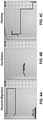
- FIGs. 4A-4C provide a series of still images from a time lapse movie showing examples of spontaneous migration behaviors exhibited by neutrophils present in a sample collected from a sepsis patient.
- the track lines in the panels of FIGs. 4A-4C show examples of reverse migration (4A), oscillation (4B), and pausing (4C) by neutrophils in the migration channels and migration chamber of the device.
- the microfluidic devices disclosed herein can be used to monitor the native motility of neutrophils in a blood sample from a subject, and, in particular, identify and monitor the spontaneous migration of neutrophils into and within a space within the device without the use of a chemical gradient, e.g., an added chemoattractant, to attract the neutrophils into the space.
- the space within the device is selected and configured to have a dimension and length that allows the neutrophils to move freely in more than one direction at any given time.
- Neutrophils from blood enter such migration spaces within the device in migration channels that are sized to allow the passage of neutrophils into the lumens of the migration channels while excluding other cells types from the space. Once inside the channel lumens, the migratory behaviors of the neutrophils, e.g., the directional motility, speed, and other migratory behaviors, are observed and analyzed.
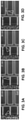
- FIG. 2A provides a macroscopic image of an example of a microfluidic device for analyzing cell motility, e.g., neutrophil motility.
- FIG. 2B is a schematic example of the microfluidic device 100 and including a close up view of a portion of the device 100.
- the microfluidic device can be used for monitoring the migratory behaviors of motile cells.
- the device 100 integrates several features, including a deeper central sample loading chamber 150 into which a small volume of blood ( ⁇ 1 to 5 ⁇ L) is loaded; a baffle filter 125, which limits entry of red blood cells (RBCs) into the channels of the assay field; and shallower migration channels 120 and a geometrical migration chamber 135 to detect and measure the directional choices (e.g., reverse migrations and oscillations), velocity, and migration persistence, e.g., persistence of direction and velocity, with high precision.
- the sample loading chamber 150 receives a fluid sample, where the fluid sample can contain multiple motile cells and non-motile cells.
- the fluid sample could be a droplet of whole blood that contains both neutrophils and red blood cells (RBCs). As shown in the example of FIG.
- the sample loading chamber 150 is surrounded by at least one migration block 110, into which a motile cell can migrate.
- Each migration block 110 is composed of at least one baffle filter 125 made up of at least one baffle passageway 115, at least one migration chamber 135, and at least one migration channel 120.
- Each migration chamber 135 of the chamber block 110 is fluidly coupled to the sample loading chamber 150 through at least one baffle filter 125 and a at least one migration channel 120.
- the baffle filter 125 is arranged in fluid communication between an outlet of the sample loading chamber 150 and the migration channel 120, such that a fluid sample deposited in the sample loading chamber can move through the baffle filter 125 into the migration channel 120.
- the migration channel 120 is arranged in fluid communication between an outlet of the baffle filter 125 and an inlet of the migration chamber 135.
- the sample loading chamber 150 has a circular profile, though other shapes can also be used.
- the diameter of the sample loading chamber 150 can be between about 10 microns to about 2000 microns.
- the diameters can be about 10, 20, 30, 40, 50, 60, 70, 80, 90, 100, 150, 200, 250, 300, 350, 400, 450, 500, 750, 1000, or 2000 microns. If the diameter is too large, it will increase the time required for the motile cells, e.g., neutrophils, far from the baffle 125 to exit the sample loading chamber and enter the next part of the device.
- the sample loading chamber 150 can have a volume in the range of about 0.5 microliters to about 20 microliters.
- the sample loading chamber 150 can have a volume of about 1, 2, 3, 4, 5, 7, 8, 10, 12, 15, 18, or 20 microliters.
- the migration chamber disclosed herein is designed to enable motile cells to migrate in one of at least two or more different directions at any given time, e.g., in two directions, in three directions, or in four directions.
- the migration chamber can be one larger chamber that allows the free movement of motile cells.
- the migration chamber can be arranged into a maze, wherein the chamber is subdivided into two or more smaller chambers separated by barriers, e.g., substrate barriers, or can be arranged into numerous passageways that are separated from each other by barriers or walls.
- the migration chamber 135 is arranged into a maze chamber wherein the chamber is subdivided by barriers into intersecting passageways that are arranged as a grid, but one of skill in the art would understand that the passageways in the maze chamber can be arranged in any pattern as long as the motile cells can migrate in one of at least two different directions at any given time.
- the migration chamber 135 has a square shaped profile in the present embodiment, but other shapes can also be used.
- the migration chamber 135 should be sized to allow the desired motile cells to pass through it freely.
- the migration chamber can be between about 10 - 2000 microns wide, 50 - 2000 microns long, and 10 - 500 microns deep.
- the width can be 10, 20, 30, 40, 50, 60, 70, 80, 90, 100, 110, 120, 130, 140, 150, 160, 170, 180, 190, 200, 250, 300, 350, 400, 450, 500, 550, 600, 650, 700, 750, 800, 850, 900, 950, 1000, or 2000 microns.
- the length can be 50, 60, 70, 80, 90, 100, 110, 120, 130, 140, 150, 160, 170, 180, 190, 200, 250, 300, 350, 400, 450, 500, 550, 600, 650, 700, 750, 800, 850, 900, 950, 1000, or 2000 microns.
- the depth can be 10, 20, 30, 40, 50, 60, 70, 80, 90, 100, 110, 120, 130, 140, 150, 160, 170, 180, 190, 200, 250, 300, 350, 400, 450, or 500 microns.
- the sample loading chamber 150 is filled with the fluid sample.
- Cells within the fluid sample begin moving toward the openings of the baffle filter(s) 125.
- Cell movement does not occur based on external pressure source (e.g., introducing pressure differences using syringe pumps or liquid pumps) or any flow of the liquid within the device.
- cell movement through the fluid in the device is the result of a combination of passive factors, including a static pressure difference created by filling the sample loading chamber with the fluid sample, natural diffusion, and/or random Brownian motion, and the motion of motile cells (e.g., by "crawling" in the case of neutrophils or swimming for other motile cells such as certain bacteria and sperm) towards the baffle filter(s) 125.
- Cell movement in the fluid sample is not based on the presence of an added attractant gradient in the device, e.g., a chemoattractant.
- the baffle filter 125 is configured to inhibit the movement of undesired cells to a greater extent than the desired motile cells.
- the baffle filter 125 includes one or more passageways 115 sized to selectively allow migration of the desired motile cells, while being small enough to substantially block the movement of other undesired motile and non-motile cells into the migration channel 120.
- the dimensions of the passageways are sized to allow migration of neutrophils in the blood sample, while being small enough to substantially impede the passage of other cells in the sample, such as RBCs and other leukocytes (e.g., monocytes and lymphocytes).
- neutrophils are generally the same size or larger than RBCs and other leukocytes (e.g., a typical human neutrophil is between about 8-15 microns in diameter; typical human lymphocytes and monocytes have diameters of about 7 microns and between about 10-30 microns, respectively; a typical disc-shaped human RBC has a diameter between about 6-8 microns and a height between about 2-2.5 microns), neutrophils are more deformable in shape than RBCs and other blood cells, and thus can change dimensions to migrate through tight passages that would otherwise impede the movement of other leukocytes and RBCs.
- FIGs. 3A-D depict a series of still images from a time-lapse movie showing that after the blood droplet is pipetted into the central sample loading chamber, the neutrophils spontaneously migrate through the RBC filter and into the migration channels and migration chamber, while the RBCs are excluded from entering the migration channels.
- Time-lapse imaging of the migration channels and migration chambers is used to measure neutrophil behavior over a period of time, e.g., 4 or more hours.
- One way of appropriately sizing the baffle passageways 115 to allow neutrophils, but not other cells to pass through, is to restrict the cross-sectional area of the passageway along a plane normal to the direction of cell movement.
- cross-sectional areas that are smaller than that of the undesired cells could also impede the desired motile cell migration, because such cells would have no gaps to pass through.
- the cross-sectional areas of the passageways 115 and/or of the migration channels 120 are configured to be larger than the largest diameter or cross-sectional dimension of one or more of the different undesired cells.
- a first dimension of the passageway 115 and/or migration channel 120 cross-section is configured to be about equal to or less than a size of the undesired cell.
- a first dimension of the cross-section e.g., width
- a second dimension of the cross-section e.g., height
- the movement of undesired cells relative to the movement of desired motile cells also can also be restricted by adding a relatively sharp turn in the baffle passageway 115 or migration channel 120, e.g., a turn of at least about 90 degrees.
- a relatively sharp turn creates congestion/gridlock in the movement of undesired cells.
- a cell moves, tumbles, floats, or is pushed into the corner, it tends to block the advance of other trailing cells behind it by restricting the cross-section of the channel to less than the diameter of a single cell.
- This configuration works well for cells that move based on granular flow (e.g., RBCs), because the granular flow force pushing the cells in the channel is not enough to deform the cells through the restricted section.
- Both the baffle filter 125 and the migration channel 120 are sized to allow the desired motile cell to pass from the sample loading chamber 150 to the migration chamber 135.
- the baffle filter 125 can include a single passageway 115 or multiple passageways 115, each of which is in fluid communication with the inlet of a migration channel 120 and each of which is configured to inhibit movement of undesired cells as described above.
- the baffle filter 125 includes several passageways 115 that together create a comb-like structure.
- the baffle filter 125 can include, but is not limited to, between 1 and 50 passageways, e.g., 15, 16, 17, 18, 19, or 20 passageways.
- the lengths i.e., the distance along the direction of cell movement into the migration channel 120
- the length can be between about 20 to about 80 microns, between about 30 to about 70 microns, or between about 40 to about 60 microns. In some embodiments, the length is 50 microns.
- the migration channel 120 should be sized to allow at least the desired cells to pass, e.g., "squeeze," through.
- the height of the migration channel 120 can be between about 8 and 20 microns, though larger heights also can be used.
- the lengths (distance along the direction of migration) of the migration channel 120 can be between about 10-2000 microns, e.g., 75 microns long.
- the widths of the migration channel 120 can be between about 8-12 microns, though other widths can also be used.
- One or more migration channels 120 are in fluid communication at one end with the baffle filter 125 through one or more baffle passageways 115, and are in fluid communication at the other end with one or more migration chambers 135.
- the migration block 110 can include, but is not limited to, between 1 and 100 migration channels 120 that join the baffle filter 125 to the migration chamber 135, e.g., 1, 2, 3, 4, 5, 6, 7, 8, 9, 10, 11, 12, 13, 14, 15, 16, 17, 18, 19, 20, 21, 22, 23, 24, 25, 26, 27, 28, 29, 30, 35, 40, 45, 50, 55, 60, 65, 70, 75, 80, 85, 90, 95, or 100 migration channels 120.
- the migration channels 120 can run directly and along the shortest distance from the baffle filter 125 to the migration chamber 135.
- the migration channels 120 can run along a more indirect route between the baffle filter 125 and the migration chamber 135, e.g., any indirect route between the baffle filter 125 and migration chamber 135 that fits physically within the confines of the migration block 110.
- the example device includes several migration channels 120 that run parallel to each other directly from the baffle filter 125 to the migration chamber 135.
- microfluidic devices described herein can be manufactured using various methods.
- devices described herein are fabricated using standard photolithography or soft lithography techniques to generate a silicon wafer, which is used as a negative mold to generate polydimethylsiloxane (PDMS) devices.
- the mold can be formed by applying and sequentially patterning two layers of photoresist (e.g., SU8, Microchem, Newton, MA) on a silicon wafer using two photolithography masks according to known methods.
- the masks can contain features that define the different aspects of the device 100 such as the input chamber, the baffle, the migration channels, and the connecting channel/migration chamber.
- the wafer with the patterned photoresist then can be used as a master mold to form the microfluidic parts.
- a PDMS (e.g., Fisher Scientific, Fair Lawn, NJ) solution then is applied to the master mold and cured. After curing, the PDMS layer solidifies and can be peeled off the master mold.
- the solidified PDMS layer includes grooves and/or recesses corresponding to the passageways, migration channels, and migration chamber of the device 100.
- the mold pattern is designed to include the features of multiple devices 100.
- Each device can be cut out from the PDMS layer using, for example, a hole puncher (e.g., a 5 mm hole puncher).
- the sample loading chamber also can be formed by using a smaller hole puncher (e.g., a 1.2 mm diameter hole puncher) to punch out PDMS material from the PDMS layer.
- the PDMS devices then are bonded to a substrate such as a glass slide or multi-well plate (i.e., each device is positioned in a corresponding well of the well plate) (e.g., Mattek, Ashland, MA).
- a bottom surface of the PDMS devices can be plasma treated to enhance the bonding properties of the PDMS.
- FIG. 1 and FIG. 2B are schematics depicting examples of microfluidic device fabricated according to the foregoing procedures.
- the example of a microfluidic device 100 described above includes a substrate layer of glass and a top layer of PDMS in which the sample loading chamber 150, the baffle filter 125, the migration channel 120 and the migration chamber 135 are formed.
- both the substrate layer and the top layer can be PDMS substrates or other similar materials such as, e.g., plastic, glass or silicone.
- the top layer (or the bottom layer) in which the baffle filter 125, migration channel 120, and migration chamber 135 are formed should be selected to have the following characteristics.
- the layer can be gas-permeable so that air in the baffle filter 125, migration channel 120, and migration chamber 135 can be displaced through the layer, either by pumping fluid into the device and/or by placing the device under vacuum, so that air can be removed from the device, e.g., from the migration channels and migration chamber, and filled with an appropriate priming solution before a sample, e.g., a blood sample or diluted blood sample, is introduced into the loading chamber.
- the layer can be transparent so as to facilitate image capture of cell motility within the device.
- the device can be placed under a vacuum.
- the vacuum causes any air present in the channels or chambers to diffuse through the gas-permeable material of the top layer (e.g., the PDMS layer). This process removes air bubbles that would otherwise be present in the fluidic channels of the device, and which could potentially block the passage of cells through the baffle filter 125 and migration channel 120.
- the device can be placed into a desiccator, in which air pressure is reduced to a vacuum level of about 17-25 inches of water, for at least about 15 minutes.
- the device 100 is primed prior to starting the assay to allow time for degassing. In some implementations, the device 100 is primed at least 5 minutes prior adding blood to the sample loading chamber of the device to begin the assay. In some implementations, the device is primed 5, 10, 15, 20, 25, 30, 35, 40, 45, 50, 55, 60, 75, 100, 115, 130, 145, or 160 minutes before adding the blood. In some implementations, the device is primed 1, 2, 3, 4, 5, 6, 7, 8, 9, 10, 11, or 12 or more hours before adding the blood.
- device priming begins with the addition of a priming solution into the sample loading chamber and around the outside of the device 100, e.g., addition of IMDM + 10% FBS + 10% Fibronectin, physiologic serum (0.9% NaCl), plasma, plasma isolated from the same patient blood sample, IMDM + 0.5% human serum albumin (HSA), Hanks buffer + 0.5% HSA, or any other solution suitable for neutrophils to migrate.
- a priming solution into the sample loading chamber and around the outside of the device 100, e.g., addition of IMDM + 10% FBS + 10% Fibronectin, physiologic serum (0.9% NaCl), plasma, plasma isolated from the same patient blood sample, IMDM + 0.5% human serum albumin (HSA), Hanks buffer + 0.5% HSA, or any other solution suitable for neutrophils to migrate.
- HSA human serum albumin
- Media is then used to submerge the device, e.g., IMDM + 20% FBS.
- the fluid sample of interest is introduced into the sample loading chamber 150 of the device.
- samples of whole blood or samples containing isolated motile cells
- samples of whole blood can be pipetted into the sample loading chamber 150.
- some of the desired cells migrate into the passageways 115 of the baffle filter 125 and then into the migration channels 120 of the device.
- Static fluid pressure can also cause some of the cells of the sample to move, e.g., by granular flow (e.g., like grains of sand tumbling down an incline) into the passageways 115 of the baffle filter 125, where the desired motile cells begin migrating into the device.
- Various properties of the motile cells can be monitored in the device including, for example, any of the spontaneous migration patterns provided in Table 2.
- one or more of the following migration patterns are monitored in the device: the number of spontaneously migrating neutrophils; the number of neutrophils that undergo a migratory oscillation; the number of neutrophils that undergo a migratory pause; whether neutrophils reverse their migration; the average distance migrated by neutrophils; the maximum migration distance; the mean velocity of neutrophils; the mean acceleration of neutrophils; the mean distance of oscillatory migration; the mean forward migration of neutrophils away from the migration chamber, e.g., maze, entrance; the mean vertical migration of neutrophils parallel to the migration channels; the mean horizontal migration of neutrophils perpendicular to the migration channels; and the mean nucleus size of migrating neutrophils.
- the device 100 can be maintained at a temperature suitable for cell migration.
- a temperature suitable for cell migration For example, in the case of neutrophil migration, the device 100 can be placed in a biochamber and heated to about 37 °C and having a 5% CO2 atmosphere with 80% humidity to maintain the viability of the cells.
- the humidified environmental chamber can, in certain implementations, increase the observation duration by several hours.
- the devices disclosed herein are designed to be imaged using an automated fluorescent inverted compound microscope, but imaging can be performed using any commercially available brightfield/ Differential Interference Contrast (DIC) setup in combination with a brightfield tracking algorithm.
- DIC Differential Interference Contrast
- Each device can incorporate multiple imaging fields, e.g., at least 2, 4, 5, 6, 7, or 8, or more imaging fields. If monitoring a large number of fields, XY points can be set prior to loading the samples into the device. An additional field in the central sample loading chamber can be imaged to facilitate normalization of neutrophil numbers present in a loaded sample, so that comparisons of cell motility data collected from different samples loaded in different devices can be made.
- An imaging device is used to capture neutrophil migratory behaviors over a span of time from a single microfluidic device.
- the imaging device can be any microscopy system, but preferably an inverted microscope with bright field or phase illumination.
- the imaging device can include a 37°C heated stage or incubation chamber, a time-lapse camera, and an automated stage to move the device to pre-defined locations to increase the number of cells observed in one device.
- non-optical methods can also be used to monitor the migration of neutrophils in a microfluidic device, e.g., the use of electrodes integrated into migration channels to measure electrical impedance, or by measuring displacement of magnetic particles in the channels to measure alterations the magnetic field.
- Each viewing field is captured repeatedly at any time interval that allows accurate tracking of neutrophil migration, e.g., every 30 seconds, 1 minute, 2 minutes, 3 minutes, 4 minutes, 5 minutes, 10 minutes, or more.
- the total time required to record the movement of the motile cells in the device depends on various factors, including the speed at which cells spontaneously move into the device, the baffle passageway length, and the migration channel length.
- the assays are run for 4 or more hours to allow time for the blood droplet to spread throughout the central sample loading chamber and cells to migrate through the maze. Longer or shorter monitoring times also can be required, depending on the nature of the particular assay being conducted.
- the time to monitor motile cell movement in the device can be on the order of 10 minutes, 20 minutes, 30 minutes, 40 minutes, 50 minutes, 1 hour, 2 hours, 3 hours, 5 hours, 6 hours, 7 hours, 8 hours, 9 hours, 10 hours, or longer.
- the system can further include a computer system that is operatively coupled to the imaging system.
- the computer system can include a tangible computer-readable storage medium (for example, a hard disk and the like) that stores computer program instructions executable by data processing apparatus (for example, a computer system, a processor, and the like) to perform operations.
- the operations can include controlling the imaging system to capture images of the migration of cells through the device over time, e.g., through the migration channels and migration chamber.
- the computer system can receive the captured images from the imaging system, and process the images to obtain various parameters, e.g., one or more of a migration speed of motile cells, the directionality of motile cells, and consistency in the speed and directionality of the cells, e.g., changes in direction such as oscillations and reverse migrations and/or changes in speed such as pausing.
- the different behaviors of motile cells e.g., particular neutrophil spontaneous migration parameters, can be quantified by counting the number of motile cells that exhibit the particular behaviors.
- computer systems suitable for the execution of a computer program include, by way of example, general or special purpose microprocessors or both, or any other kind of central processing unit.
- a central processing unit will receive instructions and information from a read-only memory or a random access memory or both.
- the essential elements of a computer system are a central processing unit for performing or executing instructions and one or more memory devices for storing instructions and information.
- a computer system will also include, or be operatively coupled to receive information from or transfer information to, or both, one or more mass storage devices for storing information, e.g., magnetic, magneto optical disks, or optical disks.
- Computer-readable media suitable for storing computer program instructions and information include various forms of non-volatile, tangible memory, media, and memory devices, including by way of example semiconductor memory devices, e.g., EPROM, EEPROM, and flash memory devices; magnetic disks, e.g., internal hard disks or removable disks; magneto optical disks; and CD ROM and (Blue Ray) DVD-ROM disks.
- semiconductor memory devices e.g., EPROM, EEPROM, and flash memory devices
- magnetic disks e.g., internal hard disks or removable disks
- magneto optical disks e.g., CD ROM and (Blue Ray) DVD-ROM disks.
- the processor and the memory can be supplemented by, or incorporated in, special purpose logic circuitry.
- implementations of the subject matter described in this specification can be implemented on a computer system having a display device, e.g., a CRT (cathode ray tube) or LCD (liquid crystal display) monitor, for displaying information to the user and a keyboard and a pointing device, e.g., a mouse or a trackball, by which the user can provide input to the computer.
- a display device e.g., a CRT (cathode ray tube) or LCD (liquid crystal display) monitor
- keyboard and a pointing device e.g., a mouse or a trackball
- Other kinds of devices can be used to provide for interaction with a user as well.
- a computer system can interact with a user by sending documents to and receiving documents from a device that is used by the user; for example, by sending web pages to a web browser on a user's client device in response to requests received from the web browser.
- Implementations of the subject matter described in this specification can be implemented in a computer system that includes a back end component, e.g., as an information server, or that includes a middleware component, e.g., an application server, or that includes a front end component, e.g., a client computer having a graphical user interface or a Web browser through which a user can interact with an implementation of the subject matter described in this specification, or any combination of one or more such back end, middleware, or front end components.
- the components of the computer system can be interconnected by any form or medium of digital information communication, e.g., a communication network. Examples of communication networks include a local area network (“LAN”) and a wide area network (“WAN”), e.g., the Internet.
- LAN local area network
- WAN wide area network
- the computer systems can use various software packages to track the movement of the cells and to analyze and characterize those movements.
- cells were tracked using ImageCV ® , TrackPy ® , and SciKit-Learn ® packages in Python software, but other object tracking software can be used.
- the code requires an Audio Video Interleaved (AVI) input.
- AVI Audio Video Interleaved
- the initial processing allows for cell tracking in brightfield images.
- the background is removed and cells are tracked by size, velocity, and directionality.
- These tracks can be written to individual comma separated value (CSV) files for each imaging field.
- the specific variables for each track can include: track number, video frame, cell diameter, x position, y position, distance, and velocity.
- Post-capture analysis of the images obtained from a single microfluidic device can be used to measure and quantify any number of the migratory parameters present in Table 2, for the purposes of assigning a score to each parameter so as to diagnose sepsis.
- the computer system is configured to execute computer software applications that perform machine learning and statistical analyses of the data captured by the imaging system.
- the computer system can be configured to perform multivariate analysis to determine correlations between neutrophil migration speed and clinical parameters.
- the microfluidic device is incorporated into a disposable casing or cartridge that may be inserted into a system that includes an imager that is coupled to a computer system for analysis, e.g., time-lapse imaging and analysis of cell motility patterns.
- a computer system for analysis e.g., time-lapse imaging and analysis of cell motility patterns.
- the microfluidic device in a cartridge can be inserted in a standalone imaging device coupled to or including a computer system.
- a blood sample is added to the device for time-lapse imaging and analysis to determine the Sepsis Score.
- the cartridge containing the used microfluidic device is removed from the imaging device and can, in some embodiments, be disposed.
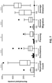
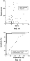
- FIG. 5 provides a flow chart of an approach to develop and optimize a machine learning model that can identify which spontaneous neutrophil migration parameters can be used in combination to diagnose sepsis with a high degree of accuracy.
- Data collected from observation of each spontaneous neutrophil migration parameter provided in Table 2 can be split 1:2:1 for training, testing, and validation steps in model development.
- the algorithm is trained on the training data. Then, variables were changed and significant variables were determined with testing data. These variables include number of cells, migration distance, oscillations, reverse migration, and pausing. With these variables, final graphs and results are produced with the held-out set.
- T-distributed stochastic neighbor embedding (tSNE) graphs are produced to visually confirm split of data by groups (sepsis, pre-sepsis, non-sepsis, and SIRS). Finally, the test-train split is changed and the analysis is run 500 - 1000 times and a histogram of the area under the radio operating characteristic (AUROC) values from the held-out data is graphed.
- FIGs. 6A-B show that each variable was validated independently (variable validation), and then in combination (Train-Test) to optimize the model.
- Sepsis Score N O + P + R + AD 10 3 , can be used to diagnose sepsis.
- the scoring system can integrate any one or more of the neutrophil motility parameters present in Table 2 to diagnose sepsis.
- one of any one of N, O, P, R, AD, MD, V, A, OD, F, VM, HM, or S is scored for a blood sample so as to predict sepsis.
- any two or more of N, O, P, R, AD, MD, V, A, OD, F, VM, HM, or S are scored for a blood sample so as to predict sepsis.
- the scoring system can integrate one or more of the number of spontaneously migrating neutrophils, the number of migratory oscillation events, the number of migratory pausing events, the number of reverse migration events, the average distance by which the neutrophils travel, the maximum migration distance, the mean velocity of neutrophils, the mean acceleration of neutrophils, the mean distance of oscillatory migration, the mean forward migration of neutrophils away from the migration chamber, e.g., maze, entrance, the mean vertical migration of neutrophils parallel to the migration channels, and the mean nucleus size of migrating neutrophils.
- one motility parameter from Table 2 is included in the Sepsis Score.
- 2, 3, 4, 5, 6, 7, 8, 9, 10, 11, 12, or 13 motility parameters from Table 2 are included in the Sepsis Score.
- a sepsis score of 30 or above indicates that a subject has sepsis or will develop sepsis.
- the Sepsis Score can be any score that can be used to diagnose sepsis in a subject based on the monitoring of neutrophils from a blood sample from the subject using the methods and devices disclosed herein.
- the Sepsis Score can be 5, 10, 15, 20, 25, 30, 35, 40, 45, 50, 55, 60, 65, 70, 75, 80, 85, 90, 95, 100, or higher.
- the Sepsis Score can be between 5 and 20, between 15 and 30, between 25 and 40, between 35 and 50, between 45 and 60, between 55 and 70, between 65 and 80, between 75 and 90, or between 85 and 100.
- the microfluidic devices and methods described herein can be used in various applications.
- the devices provide a platform for measuring the directionality and velocity of motile cells for the purposes of detecting and quantifying abnormal motility phenotypes, and determining the extent of damage to motile cells.
- the devices and methods can be used to assay samples from patients with injuries that put them at high risk of having impaired neutrophil function, e.g., over-stimulated neutrophils with impaired neutrophil directionality, so as to determine whether the patient is at enhanced risk of neutrophils migrating to healthy tissues to cause further injuries.
- the devices and methods disclosed herein can be used to diagnose a particular disease or ailment, such as sepsis or Systemic Inflammatory Response Syndrome (SIRS) or SIRS-like disorders, or predict the whether a patient is more likely to develop the particular disease or ailment.
- the devices and methods provide a platform to analyze neutrophil motility in subjects that are suspected of having sepsis or developing sepsis, e.g., hospital patients who have are at risk of developing an infection, such as ICU patients, patients with burn injuries or tissue trauma, patients undergoing chemotherapy, or patients with diabetes.
- the device can be used to test the whole blood of patients suspected of having sepsis, or determine to be at an increased risk of developing sepsis.
- An increase in one or more of the spontaneous migration parameters provided in Table 2 that establish a Sepsis Score above a certain threshold (e.g., 30 or more) indicates that the subject has sepsis or will develop sepsis.
- sepsis can be detected in a patient sample 1 to 5 days before the patient develops clinical signs of sepsis. In some implementations, the sepsis can be detected 1 day before a patient develops clinical signs of sepsis. In some implementations, the sepsis can be detected 2 days before a patient develops clinical signs of sepsis. In some implementations, the sepsis can be detected 3 days before a patient develops clinical signs of sepsis. In some implementations, the sepsis can be detected 4 days before a patient develops clinical signs of sepsis. In some implementations, the sepsis can be detected 5 days before a patient develops clinical signs of sepsis.
- the methods and devices disclosed herein can be used in a clinical context to determine whether a human or animal subject has sepsis or is more likely to develop sepsis.
- the methods and devices described herein can be used in a point-of-care clinical setting such as at a hospital or veterinary hospital.
- the devices can be used on samples of whole blood without requiring a separate isolation step for the neutrophils, thus reducing processing time.
- the use of whole blood preserves the natural environment for neutrophils without inducing neutrophil activation, thereby preserving the motility phenotype of neutrophils in sepsis samples.
- the devices can be designed to handle small quantities of fluid sample, e.g., samples having a volume of about 1 microliter.
- the devices can be used with blood obtained from humans or animal subjects. Both the reductions in sample processing time due to the use of whole blood, and the reduced sample volume requirements for the assay, are advantageous for clinical applications, where it may not be feasible to obtain larger amounts of sample fluid, e.g., in infants or small mammals.
- the methods and devices disclosed herein can be used in a veterinary setting to determine whether an animal, e.g., a mammal, has sepsis or is at a risk of developing sepsis.
- the devices can be used to determine whether a domestic animal that has been injured, has an infection, or has suffered from some other trauma, has sepsis or is more likely to develop sepsis.
- the animal can be a dog, a cat, a bird, a horse, a pig, a sheep, a goat, a cow, a buffalo, or an alpaca.
- the devices can be used to analyze efficacy of one or more medications used to treat sepsis.
- the devices can be used to monitor a patient receiving a treatment for sepsis to determine whether the treatment is effective in reducing infection.
- the medication can include, but is not limited to, one or more antibiotics, corticosteroids, and vassopressors.
- One or more antibiotics and fluids are typically administered as soon as a patient is identified as having sepsis. In most cases, a broad-spectrum antibiotic is administered first since the specific bacterium causing the infection has not been identified. A more focused antibiotic is administered once the specific bacterium is identified.
- Corticosteroids can also be administered to some patients to reduce inflammation and depress the immune system, although they are not effective for all patients.
- Vassopressors can also be administered to increase blood pressure.
- Blood samples can be obtained from the patient once or periodically after administration of the drug.
- neutrophil activity can be analyzed to determine the drug's effect on neutrophil motility.
- one or more spontaneous neutrophil motility parameters provided in Table 2 can be quantified to determine whether the neutrophils have begun to exhibit a motility phenotype more similar to that of healthy, normal cells.
- neutrophils obtained from a subject can be studied over a one-week period, for example, obtained at 24 hour intervals. If the neutrophils do not begin to exhibit the normal migratory behaviors of healthy cells, then the sepsis treatment can be altered such that a different quantity of the medication is administered or a different drug is administered. The efficacy of the altered treatment can then be tested using the device.
- the study period can be expanded to longer periods, e.g., six months, at regular intervals.
- the devices and methods disclosed herein can be used to screen for novel treatments for sepsis.
- devices loaded with a whole blood sample from a sepsis patient can be used to test the effect of hundreds, 1000s, 10,000s, or 100,000s of small molecules or other chemical agents on the cell motility of neutrophils, e.g., spontaneous cell motility of neutrophils.
- Macromolecules such as proteins, e.g., antibodies, can also be tested in this system. Reversion of the spontaneous motility of neutrophils seen in sepsis to a phenotype closer to that of neutrophils in healthy patients would indicate that tested molecule could potentially be a sepsis treatment.
- the devices and methods can be used to screen compounds to see which, if any, have an effect on any one or more of the cell motility parameters provided in Table 2.
- Example 1 Device for Monitoring Neutrophil Motility in Whole Blood
- microfluidic devices with channels and mazes were designed to monitor the migratory behaviors of neutrophils directly from whole blood samples, without the use of chemical attractants for neutrophils.
- Devices were designed using AutoCAD. Chrome masks for photolithography were printed by FrontRange Imaging (Boulder, CO). Silicon wafers were spin-coated with two layers of negative photoresist (SU-8, Microchem, Newton, MA), the first layer was 5 ⁇ m thick and the second layer was 50 ⁇ m thick. The wafers were then patterned by sequential UV exposure through two photolithography masks, and processed per manufacturer's instructions. The patterned wafers were then used as a mold for PDMS (Polydimethylsiloxane, Fisher Scientific, Fair Lawn, NJ) to produce the final PDMS devices. Central inlets were punched using a 1.2 mm punch (Harris Uni-core TM ) and the whole device cut out using a 5 mm punch. Devices were then irreversibly bonded to glass-bottom well plates (Mattek, Ashland, MA).
- PDMS Polydimethylsiloxane
- FIG. 2A shows a macroscopic image of the microfluidic device with scale
- FIG. 2B provides a schematic of the device, including a close-up illustration of the central sample loading chamber and the 8 migration blocks.
- Each migration block is composed of a baffle filter with about 18 baffle passageways that are at least 50 ⁇ m in length and 4.5 ⁇ m wide.
- the baffle passageways are connected to a series of about 19 migration channels that are approximately 500 ⁇ m in length that run directly into a migration chamber that is approximately 150 ⁇ m wide and 640 ⁇ m long.
- the migration chamber is subdivided by a series of barriers to create a grid-like series of passages that enable the neutrophils to migrate in up to 4 different possible directions, thereby providing the neutrophils with opportunities to change direction, e.g., reverse migration.
- the migration channels and the migration chamber were designed to be 10 ⁇ m wide and 10 ⁇ m high. Neutrophil motility is monitored in the migration channels and in the migration chamber.
- the device was then tested to see if it could be used for monitoring the motility of neutrophils from whole blood effectively.
- devices Prior to the addition of a blood sample, devices were primed with IMDM containing 10% FBS and 1% Fibronectin (from human plasma, Sigma) by pipetting 50 ⁇ l into the sample loading chamber and around each device, such that a dome of liquid formed on top, and the outer edge of the device in contact with the coverslip was surrounded. The devices were placed under a vacuum for at least 10 minutes, and then removed and allowed to re-pressurize and equilibrate for at least 15 minutes to remove bubbles.
- IMDM IM containing 10% FBS and 1% Fibronectin (from human plasma, Sigma)
- Peripheral blood samples from patients were drawn in 10 mL Heparin-coated vacuum tubes (Vacutainer, Becton Dickinson) from indwelling lines. Peripheral blood from healthy volunteers aged 18 years or older was also collected in Heparin-coated vacuum tubes (Research Blood Components). Some blood samples were split for comparison between the two assays using whole blood (1 mL) and isolated neutrophils (9 mL). Blood was tested in the device within the first 3 hours after being collected because neutrophil activity declines as the blood ages.
- FIGs. 3A-D show still images from a time-lapse movie illustrating that when a small volume of blood ( ⁇ 1 ⁇ L) is applied to the sample loading chamber, the baffle filter of the device selectively allowed neutrophils to pass through the filter and enter the migration channels, while preventing RBCs from entering the assay field.
- the baffle filter blocked RBCs from migrating into the migration channels with the neutrophils.
- FIGs. 3A-D show that the device as designed with a baffle filter allows neutrophils from whole blood to enter the device for observation, while effectively excluding RBCs from entering the device.
- Example 1 To understand whether analysis of neutrophil motility in whole blood could be used to diagnose or predict sepsis, the microfluidic device of Example 1 was used to analyze whole blood samples collected from healthy donors and from hospital patients having injuries or infections that make them susceptible to sepsis. The patterns of neutrophil motility were observed using time-lapse imaging for each subject population, quantified, and then compared using machine learning techniques to determine whether particular neutrophil motility parameters can be predictive of sepsis.
- Cell motility was imaged at 10x magnification using a fully automated fluorescent Nikon TiE inverted wide field microscope with a biochamber heated to 37°C with 5% CO2.
- Each microfluidic device included 8 imaging fields, each containing one migration migration chamber. Each field was imaged every 2 minutes over the course of 4 hours to allow accurate tracking of cell motility.
- FIGs. 4A --D provide still images extracted from a time-lapse movie of spontaneous migration of neutrophils from a blood sample from a septic patient. Once the neutrophils passed through the baffle filter, neutrophil velocity, directional choices, and persistence of velocity and direction were measured in the migration channels and in the migration chamber with high precision.
- the track lines in the panels of FIGs. 4A -D show examples of particular spontaneous motility behaviors that were observed, including reverse migration, oscillation, and pausing. Thus, FIGs. 4A -D illustrate that particular neutrophil motility behaviors can be identified and measured from whole blood using the microfluidic device.
- Unsupervised learning was performed to understand inherent biases in the dataset, and then supervised learning was used to identify and validate new spontaneous migration parameters to identify sepsis.
- SOFMs self-organizing feature maps
- the similarity was measured using distance metrics through Mahalanobis distance, and Euclidean distance was visualized with t-distributed stochastic neighbor embedding (t-SNE).
- SVM Support vector machines
- FIG. 5 depicts a flow chart of a machine learning process used to identify migration patterns specific to sepsis.
- Analysis applied machine learning algorithms to produce t-SNE graphs and a histogram area under the receiver operator characteristic (AUROC) curves for machines were trained on the testing data. Briefly, the data was split 1:2:1 (training data: testing data: held-out set) by patient. The algorithm was trained on the training data. Then, variables were changed and significant variables were determined with testing data. These variables include number of cells, spontaneous motility distance, oscillations, reverse migration, and pausing. With these variables, final graphs and results were produced with the held-out set.
- AUROC receiver operator characteristic
- FIGs. 6A-B illustrate that each variable was validated independently (variable validation), and then in combination (Train-Test) to optimize the model.
- tSNE analysis is applied for dimensionality reduction and visualization of high-dimensional datasets.
- the technique allows visualization of the effect various variables have on separation of the different data subsets.
- AUROC values are calculated from ROC curves created from each train-test split. These values are then plotted on a histogram from 0 to 1. The average AUROC is reported as the accuracy of the given model.
- Table 3 shows the AUROC values, the percent sensitivity, and % specificity for five individual neutrophil migration parameters. The results in Table 3 show that individual neutrophil migration parameters can predict sepsis in the derivation cohort accurately. For example, the oscillations parameter scored alone has a specificity level of 100% and a sensitivity level of 95%.
- a Sepsis Score of 30 or above indicates that the subject from whom the assayed blood sample was collected has sepsis.
- FIG. 7 shows that Septic Scores were significantly higher for five neutrophil migration parameters quantified for neutrophils from septic patient blood samples when compared to scores for neutrophils from non-septic patient blood samples (N- 87 samples; N - 23 patients). More specifically, the septic scores for the number of spontaneously migrating neutrophils, the number of oscillation events, the number of pausing events, reverse migration, and the average distance traveled were higher significantly for the sepsis samples. Neutrophil behaviors per device for non-septic and septic patient samples were normalized by the neutrophil count in the central chamber. Box and whisker plots: Tukey's boxplot. Statistics: One-way ANOVA with Tukey's multiple comparisons test.
- FIGs. 8A-E are a series of plots comparing the results from whole blood and isolated neutrophils assays run in parallel for non-septic and septic patient samples, wherein five neutrophil migration patterns were monitored. All five of the neutrophil migration parameters tested were scored significantly higher when the whole blood samples were assayed than when the isolated neutrophils were assayed. More specifically, the neutrophil migration parameters assayed were the number of spontaneously migrating neutrophils (N), oscillations (O), pausing (P), reverse migration (R), and average distance (AD). For example, neutrophils from sepsis whole blood samples exhibited many more oscillation events than the neutrophils from non-septic whole blood samples.
- N spontaneously migrating neutrophils
- O oscillations
- P pausing
- R reverse migration
- AD average distance
- Tests were also conducted to determine whether plasma factors in the blood of septic patients are responsible for the observed neutrophil spontaneous motility, and is responsible for the greater accuracy of whole blood assays in diagnosing sepsis.
- the marked increase in accuracy for the whole blood assay compared to isolated cells, raised the possibility that the difference was due to non-cell-autonomous pathways.
- a series of experiments were performed in which plasma components were exchanged between healthy and septic blood samples.
- FIGs. 9A-B show that plasma factors drive spontaneous neutrophil migration. Neutrophils from septic blood continued to exhibit spontaneous motility in the presence of healthy plasma ( FIG. 9A ), confirming that cell-autonomous pathways in septic neutrophils are not inhibited by factors present in healthy plasma.
- the transfer of patient blood cells into plasma from healthy donors reduced sepsis scores, but the scores for septic patients remain within the septic range.
- Table 4 illustrates attempts to recapitulate a sepsis-like neutrophil phenotype by spiking whole blood with various individual immune-modulators, which were previously reported to be elevated in septic blood, were unsuccessful at inducing spontaneous motility patterns.
- a "derivation" cohort of 23 patients included trauma and postoperative surgical patients admitted to the surgical intensive care unit (SICU) for trauma or surgical management (injury severity scores greater than 15, critically ill, or postoperative patients with indwelling lines). Data collected from the derivation cohort of patients was used to optimize the analysis and machine learning.
- SINU surgical intensive care unit
- a "validation cohort of 15 patients (6 septic and 9 non-septic) was then calculated to be sufficient to show that the performance of the assay, as predicted by the derivation cohort, was significantly better than the current sepsis diagnostic standard (sepsis-3, with a 0.05 probability of a type-I error and 90% power).
- a "validation" cohort of 20 patients admitted to Cardiac, Medical, and Surgical Intensive Care Units was enrolled and used for the blinded validation of the assay. Eleven patients were septic and 9 were non-septic. All blood samples were drawn with consent from patients with existing venous lines expected to remain in place for more than 48 hours.
- the first sample was drawn within first 7 days of admission to intensive care. Thereafter, a blood sample was drawn every three days for up to two weeks or until patient was discharged, relocated to another unit, or developed sepsis. During periods of sepsis, samples were drawn daily. Removal of indwelling line automatically excluded (removed) a patient from the study. Sixteen commercial blood samples from healthy donors were used as a non-patient control (Research Blood Components LLC, Allston, MA).
- patients were clinically defined as having sepsis when they were found to have a source of infection confirmed by blood, urine, or sputum culture, and evidence of organ dysfunction. If patients who were septic demonstrated signs of inadequate end organ perfusion as evidenced by persistent vasopressor requirement or had an elevated serum lactic acid level despite adequate fluid resuscitation, they were defined as having septic shock.
- patients in the first, "derivation" cohort were evaluated based on the older definition of systemic inflammatory response syndrome (SIRS).
- SIRS systemic inflammatory response syndrome
- the SIRS criteria were previously used to define a global inflammatory response, and in the setting of infection, comprised the definition of sepsis. In the setting of the SIRS criteria, septic shock included a lactic acidosis and hypotension despite adequate fluid resuscitation.
- septic shock was defined as hypotension requiring vasopressors to maintain a Mean Arterial Pressure (MAP) greater than 65 mm Hg, and a serum lactic acid above 2 mmol/dL despite adequate fluid resuscitation.
- MAP Mean Arterial Pressure
- FIG. 11 is a scatterplot showing matched SOFA and Sepsis Scores for all patient samples measured in this study. Non-sepsis scores are represented by full circles, while Sepsis samples are shown as empty circles. Samples from non-septic patients all scored below 30, while all septic samples scored above 30. Sepsis was diagnosed with 100% specificity.
- FIG. 12 is a Receiver-Operator Curve (ROC) plot showing the high specificity and sensitivity of the Sepsis Score (full circles, solid line) in correctly segregating Sepsis samples from Non-sepsis samples, compared to the SOFA score (empty circles, dashed line).
- ROC Receiver-Operator Curve
- FIGs. 10A-B , 11, and 12 show that the Sepsis Score derived from whole blood samples from 43 critically ill patients from two independent patient cohorts can be used to accurately diagnose sepsis.
- machine learning approaches were applied to assay results using blood samples collected from 23 trauma and postoperative surgical patients in order to develop a scoring system that effectively segregates patients with sepsis from those without sepsis.
- the established scoring system was validated by correctly identifying all septic individuals in a blinded study.
- neutrophil spontaneous motility measured from whole blood can diagnose sepsis with 97% sensitivity and 98% specificity in critically ill patients. This represents a significant performance improvement compared to current sepsis diagnostic capabilities and suggests that neutrophils can play more important roles in sepsis than previously appreciated.
Landscapes
- Health & Medical Sciences (AREA)
- Chemical & Material Sciences (AREA)
- Life Sciences & Earth Sciences (AREA)
- Immunology (AREA)
- Engineering & Computer Science (AREA)
- Physics & Mathematics (AREA)
- Analytical Chemistry (AREA)
- General Health & Medical Sciences (AREA)
- General Physics & Mathematics (AREA)
- Pathology (AREA)
- Biochemistry (AREA)
- Biomedical Technology (AREA)
- Dispersion Chemistry (AREA)
- Hematology (AREA)
- Molecular Biology (AREA)
- Urology & Nephrology (AREA)
- Medicinal Chemistry (AREA)
- Food Science & Technology (AREA)
- Cell Biology (AREA)
- Microbiology (AREA)
- Biotechnology (AREA)
- Physiology (AREA)
- Tropical Medicine & Parasitology (AREA)
- Clinical Laboratory Science (AREA)
- Chemical Kinetics & Catalysis (AREA)
- Biophysics (AREA)
- Signal Processing (AREA)
- Investigating Or Analysing Biological Materials (AREA)
- Computer Vision & Pattern Recognition (AREA)
Claims (14)
- Mikrofluidische Vorrichtung (100), umfassend:(a) eine Probenladekammer (150), die eine Vielzahl von Auslässen umfasst,(b) eine Migrationskammer (135) mit einer Vielzahl von Einlässen, und die ausgestaltet und bemessen ist, um motilen Zellen eine Wahl der direktionalen Migration bereitzustellen, und(c) eine Vielzahl von Migrationskanälen (120), die in Fluidkommunikation zwischen dem einen oder den mehreren Auslässen der Probenladekammer (150) und dem einen oder den mehreren Einlässen der Migrationskammer (135) angeordnet sind, wobei jeder Migrationskanal (120) so verbunden ist, dass einer Probe das Fließen von einem Auslass der Probenladekammer (150) zu einem Einlass der Migrationskammer (135) ermöglicht wird, wobei die Migrationskanäle (120) so bemessen sind, dass die Migration von Neutrophilen zugelassen wird, und(d) einen Prallkörper (125), der in Fluidkommunikation zwischen den Auslässen der Probenladekammer (150) und den Migrationskanälen (120) oder innerhalb der Migrationskanäle (120) angeordnet ist, jedoch an einem Punkt, bevor jeder Migrationskanal (120) in einen Einlass der Migrationskammer (135) eintritt, wobei der Prallkörper (125) einen oder mehrere Durchgänge (115) umfasst, die ausgestaltet sind, um die Bewegung von roten Blutkörperchen durch den Prallkörper (125) hindurch in einem größeren Maß zu inhibieren, als der Prallkörper (125) Bewegung der Neutrophilen durch den Prallkörper (125) hindurch inhibiert,dadurch gekennzeichnet, dass die mikrofluidische Vorrichtung (100) des Weiteren eine Pufferflüssigkeit umfasst, die keinen exogenen chemischen Lockstoff einschließt.
- Mikrofluidische Vorrichtung (100) nach Anspruch 1, wobei Einlassenden der Migrationskanäle (120) so bemessen sind, dass rote Blutkörperchen in einem größeren Ausmaß als Neutrophile vom Eintreten in die Migrationskanäle (120) ausgeschlossen werden.
- Mikrofluidische Vorrichtung (100) nach Anspruch 1, wobei eine Querschnittfläche des Prallkörperdurchgangs (115) senkrecht zu dem Probentransportpfad in dem Prallkörperdurchgang (115) kleiner als eine Querschnittfläche eines roten Blutkörperchens ist, und wobei eine Breite der Querschnittfläche kleiner als der Durchmesser eines roten Blutkörperchens ist.
- Mikrofluidische Vorrichtung (100) nach Anspruch 3, des Weiteren umfassend einen Austrittskanal in Fluidkommunikation mit dem Migrationskanal (120) an einem Punkt hinter dem Prallkörper (125) und bevor der Migrationskanal (120) in den Einlass der Migrationskammer (135) eintritt.
- Mikrofluidische Vorrichtung (100) nach einem der Ansprüche 1 bis 4, wobei die Querschnittfläche der Migrationskanäle (120) oder Prallkörperdurchgänge (115) größer als eine Querschnittfläche der roten Blutkörperchen ist, und wobei Migrationskanäle (120) oder Prallkörperdurchgänge (115) mindestens eine Wegbiegung aufweisen, so dass rote Blutkörperchen daran gehindert werden, an der Wegbiegung vorbei zu kommen.
- Mikrofluidische Vorrichtung (100) nach Anspruch 3, wobei die Vorrichtung umfasst:eine Vielzahl von Prallkörperdurchgängen (115); undeine Vielzahl von Migrationskanälen (120); wobei jeder Prallkörperdurchgang (115) in Fluidkommunikation mit einem Migrationskanal (120) ist, undwobei die Migrationskanäle (120) und die Migrationskammer (135) jeweils ein transparentes Abdeckmaterial umfassen, um zu ermöglichen, dass die Motilität der Neutrophilen in den Migrationskanälen (120) und der Migrationskammer (135) überwacht wird.
- Mikrofluidische Vorrichtung (100) nach einem der Ansprüche 1 bis 6, wobei die mikrofluidische Vorrichtung (100) ein Substrat umfasst, und wobei die Kammern und Kanäle der Vorrichtung in Fluidkommunikation auf dem Substrat angeordnet sind.
- Verfahren zum Überwachen der Motilität von Neutrophilen in einer mikrofluidischen Vorrichtung (100) nach einem der Ansprüche 1 bis 7, wobei das Verfahren umfasst:(a) Zufügen einer Blutprobe zu der Probenladekammer (150) der mikrofluidischen Vorrichtung (100), die eine Vielzahl von Migrationskanälen (120) umfasst, die jeweils eine erste Endgröße haben, um Neutrophilen das Eintreten in die Migrationskanäle (120) zu gestatten; und(b) Überwachen von spontaner Motilität von einem oder mehreren Neutrophilen in dem einen oder den mehreren Migrationskanälen (120) in Abwesenheit eines exogen zugefügten chemischen Lockstoffgradienten.
- Verfahren nach Anspruch 8,wobei das Verfahren des Weiteren Inkubieren der mikrofluidischen Vorrichtung (100) unter Bedingungen und für eine Zeit umfasst, die ausreichen, um Bewegung der Neutrophilen in der Probe aus der Probenladekammer (150) in die Migrationskanäle (120) zu ermöglichen; undÜberwachen von spontaner Motilität von einem oder mehreren Neutrophilen in dem einen oder den mehreren Migrationskanälen (120) und der Migrationskammer (135).
- Verfahren nach einem der Ansprüche 8 bis 9, wobei Überwachen der Motilität von Neutrophilen Quantifizieren von einem oder mehreren von Geschwindigkeit, Migrationsdistanz, Migrationsrichtung, Geschwindigkeitspersistenz und direktionaler Persistenz von Neutrophilen in den Migrationskanälen (120) umfasst.
- Verfahren nach einem der Ansprüche 8 bis 10, wobei Überwachen der Motilität von Neutrophilen Quantifizieren von zwei oder mehr Neutrophilenmotilitätsparametern ausgewählt aus der Gruppe umfasst, die besteht aus:(a) Anzahl der spontan migrierenden Neutrophilen;(b) Anzahl der Neutrophilen, die eine migratorische Oszillation eingehen;(c) Anzahl der Neutrophilen, die eine migratorische Pause eingehen;(d) ob Neutrophile ihre Migration umkehren;(e) durchschnittliche Distanz, die Neutrophile migrieren;(f) maximaler Migrationsdistanz;(g) mittlerer Geschwindigkeit der Neutrophilen;(h) mittlerer Beschleunigung der Neutrophilen;(i) mittlerer Distanz der oszillatorischen Migration;(j) mittlerer Vorwärtsmigration von Neutrophilen, die vom Eingang der Migrationskammer (135) weg führt;(k) mittlerer vertikaler Migration von Neutrophilen parallel zu den Migrationskanälen (120);(l) mittlerer horizontaler Migration von Neutrophilen senkrecht zu den Migrationskanälen (120); und(m) mittlerer Nukleusgröße der migrierenden Neutrophilen.
- Verfahren nach Anspruch 11, des Weiteren umfassend Ermitteln eines Sepsis-Scores durch Kombinieren der quantifizierten Ergebnisse für die Neutrophilenmotilitätsparameter; und wobei ein Sepsis-Score, der oberhalb eines bestimmten Schwellenwerts liegt, angibt, dass das Subjekt Sepsis hat oder entwickeln wird, wobei ein Sepsis-Score gegebenenfalls unter Verwendung der folgenden Formel ermittelt wird:

- Verfahren zum Diagnostizieren von Sepsis bei einem Subjekt, wobei das Verfahren umfasst:(a) Erhalten einer Vorrichtung (100) nach einem der Ansprüche 1 bis 7;(b) Zufügen einer Blutprobe zu der Probenladekammer (150);(c) Inkubieren der Vorrichtung (100) unter Bedingungen und für eine Zeit, die ausreichen, um Bewegung von Zellen in der Probe aus der Probenladekammer (150) in den Migrationskanal (120) zu ermöglichen; und(d) Überwachen der Motilität von einem oder mehreren Neutrophilen in den Migrationskanälen (120) und/oder der Migrationskammer (135);
wobei Überwachen der Motilität von Neutrophilen Quantifizieren der folgenden Neutrophilenmotilitätsparameter umfasst:Anzahl der spontan migrierenden Neutrophilen;Anzahl der Neutrophilen, die eine migratorische Oszillation eingehen;Anzahl der Neutrophilen, die eine migratorische Pause eingehen;ob Neutrophile ihre Migration umkehren; unddurchschnittliche Distanz, die Neutrophile migrieren; und(e) Ermitteln eines Sepsis-Scores durch Kombinieren der quantifizierten Ergebnisse für die Neutrophilenmotilitätsparameter unter Verwendung der Formel
- Verfahren nach Anspruch 13, des Weiteren umfassend Quantifizieren von einem oder mehreren Neutrophilenmotilitätsparametern ausgewählt aus der Gruppe bestehend aus:maximaler Migrationsdistanz;mittlerer Geschwindigkeit der Neutrophilen;mittlerer Beschleunigung der Neutrophilen;mittlerer Distanz der oszillatorischen Migration;mittlerer Vorwärtsmigration von Neutrophilen, die vom Eingang der Migrationskammer (135) weg führt;mittlerer vertikaler Migration von Neutrophilen parallel zu den Migrationskanälen (120);mittlerer horizontaler Migration von Neutrophilen senkrecht zu den Migrationskanälen (120); undmittlerer Nukleusgröße der migrierenden Neutrophilen.
Applications Claiming Priority (3)
| Application Number | Priority Date | Filing Date | Title |
|---|---|---|---|
| US201662332659P | 2016-05-06 | 2016-05-06 | |
| US201662418562P | 2016-11-07 | 2016-11-07 | |
| PCT/US2017/031557 WO2017193126A1 (en) | 2016-05-06 | 2017-05-08 | Microfluidic neutrophil assays and systems for disease detection |
Publications (3)
| Publication Number | Publication Date |
|---|---|
| EP3452221A1 EP3452221A1 (de) | 2019-03-13 |
| EP3452221A4 EP3452221A4 (de) | 2019-08-28 |
| EP3452221B1 true EP3452221B1 (de) | 2022-02-23 |
Family
ID=60203466
Family Applications (1)
| Application Number | Title | Priority Date | Filing Date |
|---|---|---|---|
| EP17793545.9A Active EP3452221B1 (de) | 2016-05-06 | 2017-05-08 | Mikrofluidische neutrophilentests und systeme zur erkennung von erkrankungen |
Country Status (3)
| Country | Link |
|---|---|
| US (1) | US11130132B2 (de) |
| EP (1) | EP3452221B1 (de) |
| WO (1) | WO2017193126A1 (de) |
Families Citing this family (8)
| Publication number | Priority date | Publication date | Assignee | Title |
|---|---|---|---|---|
| US10664978B2 (en) * | 2018-04-09 | 2020-05-26 | The University Of North Carolina At Chapel Hill | Methods, systems, and computer readable media for using synthetically trained deep neural networks for automated tracking of particles in diverse video microscopy data sets |
| JP2021522519A (ja) * | 2018-04-19 | 2021-08-30 | スティッキーセル ピーティーワイ リミテッドStickycell Pty Ltd | 感染症の技術分野における白血球補充 |
| GB2575494A (en) * | 2018-07-12 | 2020-01-15 | Zellmechanik Dresden Gmbh | Method of obtaining an indicator of patient sepsis and apparatus for such a method |
| US11123734B2 (en) | 2019-07-31 | 2021-09-21 | CytoVale Inc. | System and method for immune activity determination |
| CN110713923B (zh) * | 2019-10-11 | 2023-06-23 | 晶准生物医学(深圳)有限公司 | 微流控芯片装置及其在癌细胞迁移分析中的应用 |
| US11592371B1 (en) | 2022-01-13 | 2023-02-28 | CytoVale Inc. | System and method for determining an immune activation state |
| US11548003B1 (en) | 2022-01-13 | 2023-01-10 | CytoVale Inc. | System and method for determining an immune activation state |
| US11964281B2 (en) | 2022-02-03 | 2024-04-23 | CytoVale Inc. | System and method for correcting patient index |
Family Cites Families (17)
| Publication number | Priority date | Publication date | Assignee | Title |
|---|---|---|---|---|
| US5744366A (en) | 1992-05-01 | 1998-04-28 | Trustees Of The University Of Pennsylvania | Mesoscale devices and methods for analysis of motile cells |
| EP1101106A4 (de) | 1998-07-28 | 2006-05-03 | Bd Biosciences Systems And Rea | Anordnung und verfahren zum test für zellenbeweglichkeit |
| US6921660B2 (en) | 2000-11-08 | 2005-07-26 | Surface Logix, Inc. | Cell motility and chemotaxis test device and methods of using same |
| US7374906B2 (en) | 2000-11-08 | 2008-05-20 | Surface Logix, Inc. | Biological assays using gradients formed in microfluidic systems |
| US6699665B1 (en) * | 2000-11-08 | 2004-03-02 | Surface Logix, Inc. | Multiple array system for integrating bioarrays |
| US7326563B2 (en) | 2000-11-08 | 2008-02-05 | Surface Logix, Inc. | Device and method for monitoring leukocyte migration |
| AU2002217953A1 (en) | 2000-11-28 | 2002-06-11 | Transform Pharmaceuticals, Inc. | Rapid identification of conditions, compounds, or compositions that inhibit, prevent, induce, modify, or reverse transitions of physical state |
| CA2500392C (en) | 2002-09-27 | 2012-11-27 | The General Hospital Corporation | Microfluidic device for cell separation and uses thereof |
| US7773227B2 (en) | 2004-06-04 | 2010-08-10 | California Institute Of Technology | Optofluidic microscope device featuring a body comprising a fluid channel and having light transmissive regions |
| WO2009102453A2 (en) | 2008-02-11 | 2009-08-20 | The General Hospital Corporation | System and method for quantitative assessment of biological migration behavior |
| WO2010036913A2 (en) | 2008-09-26 | 2010-04-01 | The General Hospital Corporation | Quantifying cell migration in wound healing assays |
| WO2010108095A2 (en) | 2009-03-19 | 2010-09-23 | The General Hospital Corporation | Microfluidic cell motility assay |
| US20110124025A1 (en) | 2009-11-20 | 2011-05-26 | College Of Nanoscale Science And Engineering | Cell Collecting Devices and Methods for Collecting Cells |
| CN101914435B (zh) * | 2010-05-24 | 2013-08-21 | 博奥生物有限公司 | 一种微管道装置及其使用方法 |
| US20120216601A1 (en) | 2011-02-28 | 2012-08-30 | The General Hospital Corporation | Microfluidic devices for analyzing cell motility |
| US8673628B2 (en) | 2011-06-10 | 2014-03-18 | Essen Instruments, Inc. | Methods and apparatus for improving in vitro measurements using boyden chambers |
| WO2015042436A1 (en) * | 2013-09-20 | 2015-03-26 | The General Hospital Corporation | Cell chemotaxis assays |
-
2017
- 2017-05-08 EP EP17793545.9A patent/EP3452221B1/de active Active
- 2017-05-08 WO PCT/US2017/031557 patent/WO2017193126A1/en not_active Ceased
- 2017-05-08 US US16/099,117 patent/US11130132B2/en active Active
Also Published As
| Publication number | Publication date |
|---|---|
| EP3452221A1 (de) | 2019-03-13 |
| WO2017193126A1 (en) | 2017-11-09 |
| EP3452221A4 (de) | 2019-08-28 |
| US11130132B2 (en) | 2021-09-28 |
| US20190143326A1 (en) | 2019-05-16 |
Similar Documents
| Publication | Publication Date | Title |
|---|---|---|
| EP3452221B1 (de) | Mikrofluidische neutrophilentests und systeme zur erkennung von erkrankungen | |
| Ellett et al. | Diagnosis of sepsis from a drop of blood by measurement of spontaneous neutrophil motility in a microfluidic assay | |
| Boya et al. | High throughput, label-free isolation of circulating tumor cell clusters in meshed microwells | |
| Barber et al. | Parasite biomass-related inflammation, endothelial activation, microvascular dysfunction and disease severity in vivax malaria | |
| Kim et al. | Label-free single-cell antimicrobial susceptibility testing in droplets with concentration gradient generation | |
| Pfammatter et al. | Absolute quantification of amyloid propagons by digital microfluidics | |
| Otawara et al. | Microfluidic assay measures increased neutrophil extracellular traps circulating in blood after burn injuries | |
| US11460465B2 (en) | Cell chemotaxis assays | |
| Jones et al. | Microfluidic platform for measuring neutrophil chemotaxis from unprocessed whole blood | |
| Goddard et al. | Platelet indices in dogs with Babesia rossi infection | |
| Man et al. | OcclusionChip: A functional microcapillary occlusion assay complementary to ektacytometry for detection of small-fraction red blood cells with abnormal deformability | |
| Claxton et al. | The challenge of recognising sepsis: Future nanotechnology solutions | |
| Siddiqui et al. | Evaluation of gammah2ax in buccal cells as a molecular biomarker of DNA damage in Alzheimer’s disease in the AIBL study of ageing | |
| US20220388002A1 (en) | Microfluidic device and uses thereof | |
| US8980566B2 (en) | Biomarkers for respiratory infection | |
| Aune et al. | Automated counting of white and red blood cells in the cerebrospinal fluid | |
| CN112352159A (zh) | 传染病中的白细胞募集情况 | |
| Michael et al. | Clinical parameters of hypervirulent Klebsiella pneumoniae disease and ivermectin treatment in New Zealand sea lion (Phocarctos hookeri) pups | |
| US20250281929A1 (en) | Microfluidic device and uses thereof | |
| Ellett et al. | Passive redirection filters minimize red blood cell contamination during neutrophil chemotaxis assays using whole blood | |
| Juang et al. | Micro blood analysis technology (μBAT): multiplexed analysis of neutrophil phenotype and function from microliter whole blood samples | |
| Abbott et al. | STRESS HISTORY ESTABLISHES A TRANSIENT TOLERANT STATE THAT SHAPES ANTIBIOTIC SURVIVAL UPON RESUSCITATION | |
| Onder et al. | Detecting the prevalence of bacterial colonization on tunneled cuffed hemodialysis catheters using quantitative PCR targeting 16S rRNA and scanning electron microscopy | |
| US20240390902A1 (en) | Methods and systems for sorting biological particles | |
| Li et al. | In vitro neutrophil functional assay in microliter whole blood for days-long extraction of donor-specific information |
Legal Events
| Date | Code | Title | Description |
|---|---|---|---|
| STAA | Information on the status of an ep patent application or granted ep patent |
Free format text: STATUS: THE INTERNATIONAL PUBLICATION HAS BEEN MADE |
|
| PUAI | Public reference made under article 153(3) epc to a published international application that has entered the european phase |
Free format text: ORIGINAL CODE: 0009012 |
|
| STAA | Information on the status of an ep patent application or granted ep patent |
Free format text: STATUS: REQUEST FOR EXAMINATION WAS MADE |
|
| 17P | Request for examination filed |
Effective date: 20181204 |
|
| AK | Designated contracting states |
Kind code of ref document: A1 Designated state(s): AL AT BE BG CH CY CZ DE DK EE ES FI FR GB GR HR HU IE IS IT LI LT LU LV MC MK MT NL NO PL PT RO RS SE SI SK SM TR |
|
| AX | Request for extension of the european patent |
Extension state: BA ME |
|
| RIC1 | Information provided on ipc code assigned before grant |
Ipc: G01N 33/50 20060101ALI20190418BHEP Ipc: G01N 15/02 20060101ALI20190418BHEP Ipc: B01L 3/00 20060101AFI20190418BHEP Ipc: G01N 33/543 20060101ALI20190418BHEP |
|
| DAV | Request for validation of the european patent (deleted) | ||
| DAX | Request for extension of the european patent (deleted) | ||
| A4 | Supplementary search report drawn up and despatched |
Effective date: 20190731 |
|
| RIC1 | Information provided on ipc code assigned before grant |
Ipc: B01L 3/00 20060101AFI20190725BHEP Ipc: G01N 15/02 20060101ALI20190725BHEP Ipc: G01N 33/543 20060101ALI20190725BHEP Ipc: G01N 33/50 20060101ALI20190725BHEP |
|
| STAA | Information on the status of an ep patent application or granted ep patent |
Free format text: STATUS: EXAMINATION IS IN PROGRESS |
|
| 17Q | First examination report despatched |
Effective date: 20201103 |
|
| GRAP | Despatch of communication of intention to grant a patent |
Free format text: ORIGINAL CODE: EPIDOSNIGR1 |
|
| STAA | Information on the status of an ep patent application or granted ep patent |
Free format text: STATUS: GRANT OF PATENT IS INTENDED |
|
| INTG | Intention to grant announced |
Effective date: 20210531 |
|
| GRAJ | Information related to disapproval of communication of intention to grant by the applicant or resumption of examination proceedings by the epo deleted |
Free format text: ORIGINAL CODE: EPIDOSDIGR1 |
|
| STAA | Information on the status of an ep patent application or granted ep patent |
Free format text: STATUS: EXAMINATION IS IN PROGRESS |
|
| GRAP | Despatch of communication of intention to grant a patent |
Free format text: ORIGINAL CODE: EPIDOSNIGR1 |
|
| STAA | Information on the status of an ep patent application or granted ep patent |
Free format text: STATUS: GRANT OF PATENT IS INTENDED |
|
| INTC | Intention to grant announced (deleted) | ||
| INTG | Intention to grant announced |
Effective date: 20210927 |
|
| RIN1 | Information on inventor provided before grant (corrected) |
Inventor name: JORGENSEN, JULIANNE Inventor name: ELLETT, FELIX Inventor name: IRIMIA, DANIEL |
|
| GRAS | Grant fee paid |
Free format text: ORIGINAL CODE: EPIDOSNIGR3 |
|
| GRAA | (expected) grant |
Free format text: ORIGINAL CODE: 0009210 |
|
| STAA | Information on the status of an ep patent application or granted ep patent |
Free format text: STATUS: THE PATENT HAS BEEN GRANTED |
|
| AK | Designated contracting states |
Kind code of ref document: B1 Designated state(s): AL AT BE BG CH CY CZ DE DK EE ES FI FR GB GR HR HU IE IS IT LI LT LU LV MC MK MT NL NO PL PT RO RS SE SI SK SM TR |
|
| REG | Reference to a national code |
Ref country code: GB Ref legal event code: FG4D |
|
| REG | Reference to a national code |
Ref country code: CH Ref legal event code: EP |
|
| REG | Reference to a national code |
Ref country code: AT Ref legal event code: REF Ref document number: 1470012 Country of ref document: AT Kind code of ref document: T Effective date: 20220315 |
|
| REG | Reference to a national code |
Ref country code: IE Ref legal event code: FG4D |
|
| REG | Reference to a national code |
Ref country code: DE Ref legal event code: R096 Ref document number: 602017053760 Country of ref document: DE |
|
| REG | Reference to a national code |
Ref country code: LT Ref legal event code: MG9D |
|
| REG | Reference to a national code |
Ref country code: NL Ref legal event code: MP Effective date: 20220223 |
|
| REG | Reference to a national code |
Ref country code: AT Ref legal event code: MK05 Ref document number: 1470012 Country of ref document: AT Kind code of ref document: T Effective date: 20220223 |
|
| PG25 | Lapsed in a contracting state [announced via postgrant information from national office to epo] |
Ref country code: SE Free format text: LAPSE BECAUSE OF FAILURE TO SUBMIT A TRANSLATION OF THE DESCRIPTION OR TO PAY THE FEE WITHIN THE PRESCRIBED TIME-LIMIT Effective date: 20220223 Ref country code: RS Free format text: LAPSE BECAUSE OF FAILURE TO SUBMIT A TRANSLATION OF THE DESCRIPTION OR TO PAY THE FEE WITHIN THE PRESCRIBED TIME-LIMIT Effective date: 20220223 Ref country code: PT Free format text: LAPSE BECAUSE OF FAILURE TO SUBMIT A TRANSLATION OF THE DESCRIPTION OR TO PAY THE FEE WITHIN THE PRESCRIBED TIME-LIMIT Effective date: 20220623 Ref country code: NO Free format text: LAPSE BECAUSE OF FAILURE TO SUBMIT A TRANSLATION OF THE DESCRIPTION OR TO PAY THE FEE WITHIN THE PRESCRIBED TIME-LIMIT Effective date: 20220523 Ref country code: NL Free format text: LAPSE BECAUSE OF FAILURE TO SUBMIT A TRANSLATION OF THE DESCRIPTION OR TO PAY THE FEE WITHIN THE PRESCRIBED TIME-LIMIT Effective date: 20220223 Ref country code: LT Free format text: LAPSE BECAUSE OF FAILURE TO SUBMIT A TRANSLATION OF THE DESCRIPTION OR TO PAY THE FEE WITHIN THE PRESCRIBED TIME-LIMIT Effective date: 20220223 Ref country code: HR Free format text: LAPSE BECAUSE OF FAILURE TO SUBMIT A TRANSLATION OF THE DESCRIPTION OR TO PAY THE FEE WITHIN THE PRESCRIBED TIME-LIMIT Effective date: 20220223 Ref country code: ES Free format text: LAPSE BECAUSE OF FAILURE TO SUBMIT A TRANSLATION OF THE DESCRIPTION OR TO PAY THE FEE WITHIN THE PRESCRIBED TIME-LIMIT Effective date: 20220223 Ref country code: BG Free format text: LAPSE BECAUSE OF FAILURE TO SUBMIT A TRANSLATION OF THE DESCRIPTION OR TO PAY THE FEE WITHIN THE PRESCRIBED TIME-LIMIT Effective date: 20220523 |
|
| PG25 | Lapsed in a contracting state [announced via postgrant information from national office to epo] |
Ref country code: PL Free format text: LAPSE BECAUSE OF FAILURE TO SUBMIT A TRANSLATION OF THE DESCRIPTION OR TO PAY THE FEE WITHIN THE PRESCRIBED TIME-LIMIT Effective date: 20220223 Ref country code: LV Free format text: LAPSE BECAUSE OF FAILURE TO SUBMIT A TRANSLATION OF THE DESCRIPTION OR TO PAY THE FEE WITHIN THE PRESCRIBED TIME-LIMIT Effective date: 20220223 Ref country code: GR Free format text: LAPSE BECAUSE OF FAILURE TO SUBMIT A TRANSLATION OF THE DESCRIPTION OR TO PAY THE FEE WITHIN THE PRESCRIBED TIME-LIMIT Effective date: 20220524 Ref country code: FI Free format text: LAPSE BECAUSE OF FAILURE TO SUBMIT A TRANSLATION OF THE DESCRIPTION OR TO PAY THE FEE WITHIN THE PRESCRIBED TIME-LIMIT Effective date: 20220223 Ref country code: AT Free format text: LAPSE BECAUSE OF FAILURE TO SUBMIT A TRANSLATION OF THE DESCRIPTION OR TO PAY THE FEE WITHIN THE PRESCRIBED TIME-LIMIT Effective date: 20220223 |
|
| PG25 | Lapsed in a contracting state [announced via postgrant information from national office to epo] |
Ref country code: IS Free format text: LAPSE BECAUSE OF FAILURE TO SUBMIT A TRANSLATION OF THE DESCRIPTION OR TO PAY THE FEE WITHIN THE PRESCRIBED TIME-LIMIT Effective date: 20220623 |
|
| PG25 | Lapsed in a contracting state [announced via postgrant information from national office to epo] |
Ref country code: SM Free format text: LAPSE BECAUSE OF FAILURE TO SUBMIT A TRANSLATION OF THE DESCRIPTION OR TO PAY THE FEE WITHIN THE PRESCRIBED TIME-LIMIT Effective date: 20220223 Ref country code: SK Free format text: LAPSE BECAUSE OF FAILURE TO SUBMIT A TRANSLATION OF THE DESCRIPTION OR TO PAY THE FEE WITHIN THE PRESCRIBED TIME-LIMIT Effective date: 20220223 Ref country code: RO Free format text: LAPSE BECAUSE OF FAILURE TO SUBMIT A TRANSLATION OF THE DESCRIPTION OR TO PAY THE FEE WITHIN THE PRESCRIBED TIME-LIMIT Effective date: 20220223 Ref country code: EE Free format text: LAPSE BECAUSE OF FAILURE TO SUBMIT A TRANSLATION OF THE DESCRIPTION OR TO PAY THE FEE WITHIN THE PRESCRIBED TIME-LIMIT Effective date: 20220223 Ref country code: DK Free format text: LAPSE BECAUSE OF FAILURE TO SUBMIT A TRANSLATION OF THE DESCRIPTION OR TO PAY THE FEE WITHIN THE PRESCRIBED TIME-LIMIT Effective date: 20220223 Ref country code: CZ Free format text: LAPSE BECAUSE OF FAILURE TO SUBMIT A TRANSLATION OF THE DESCRIPTION OR TO PAY THE FEE WITHIN THE PRESCRIBED TIME-LIMIT Effective date: 20220223 |
|
| REG | Reference to a national code |
Ref country code: DE Ref legal event code: R097 Ref document number: 602017053760 Country of ref document: DE |
|
| PG25 | Lapsed in a contracting state [announced via postgrant information from national office to epo] |
Ref country code: AL Free format text: LAPSE BECAUSE OF FAILURE TO SUBMIT A TRANSLATION OF THE DESCRIPTION OR TO PAY THE FEE WITHIN THE PRESCRIBED TIME-LIMIT Effective date: 20220223 |
|
| PLBE | No opposition filed within time limit |
Free format text: ORIGINAL CODE: 0009261 |
|
| REG | Reference to a national code |
Ref country code: CH Ref legal event code: PL |
|
| STAA | Information on the status of an ep patent application or granted ep patent |
Free format text: STATUS: NO OPPOSITION FILED WITHIN TIME LIMIT |
|
| REG | Reference to a national code |
Ref country code: BE Ref legal event code: MM Effective date: 20220531 |
|
| PG25 | Lapsed in a contracting state [announced via postgrant information from national office to epo] |
Ref country code: MC Free format text: LAPSE BECAUSE OF FAILURE TO SUBMIT A TRANSLATION OF THE DESCRIPTION OR TO PAY THE FEE WITHIN THE PRESCRIBED TIME-LIMIT Effective date: 20220223 Ref country code: LU Free format text: LAPSE BECAUSE OF NON-PAYMENT OF DUE FEES Effective date: 20220508 Ref country code: LI Free format text: LAPSE BECAUSE OF NON-PAYMENT OF DUE FEES Effective date: 20220531 Ref country code: CH Free format text: LAPSE BECAUSE OF NON-PAYMENT OF DUE FEES Effective date: 20220531 |
|
| 26N | No opposition filed |
Effective date: 20221124 |
|
| PG25 | Lapsed in a contracting state [announced via postgrant information from national office to epo] |
Ref country code: SI Free format text: LAPSE BECAUSE OF FAILURE TO SUBMIT A TRANSLATION OF THE DESCRIPTION OR TO PAY THE FEE WITHIN THE PRESCRIBED TIME-LIMIT Effective date: 20220223 |
|
| PG25 | Lapsed in a contracting state [announced via postgrant information from national office to epo] |
Ref country code: IE Free format text: LAPSE BECAUSE OF NON-PAYMENT OF DUE FEES Effective date: 20220508 |
|
| PG25 | Lapsed in a contracting state [announced via postgrant information from national office to epo] |
Ref country code: BE Free format text: LAPSE BECAUSE OF NON-PAYMENT OF DUE FEES Effective date: 20220531 |
|
| P01 | Opt-out of the competence of the unified patent court (upc) registered |
Effective date: 20230515 |
|
| PG25 | Lapsed in a contracting state [announced via postgrant information from national office to epo] |
Ref country code: IT Free format text: LAPSE BECAUSE OF FAILURE TO SUBMIT A TRANSLATION OF THE DESCRIPTION OR TO PAY THE FEE WITHIN THE PRESCRIBED TIME-LIMIT Effective date: 20220223 |
|
| PG25 | Lapsed in a contracting state [announced via postgrant information from national office to epo] |
Ref country code: HU Free format text: LAPSE BECAUSE OF FAILURE TO SUBMIT A TRANSLATION OF THE DESCRIPTION OR TO PAY THE FEE WITHIN THE PRESCRIBED TIME-LIMIT; INVALID AB INITIO Effective date: 20170508 |
|
| PG25 | Lapsed in a contracting state [announced via postgrant information from national office to epo] |
Ref country code: MK Free format text: LAPSE BECAUSE OF FAILURE TO SUBMIT A TRANSLATION OF THE DESCRIPTION OR TO PAY THE FEE WITHIN THE PRESCRIBED TIME-LIMIT Effective date: 20220223 Ref country code: CY Free format text: LAPSE BECAUSE OF FAILURE TO SUBMIT A TRANSLATION OF THE DESCRIPTION OR TO PAY THE FEE WITHIN THE PRESCRIBED TIME-LIMIT Effective date: 20220223 |
|
| PG25 | Lapsed in a contracting state [announced via postgrant information from national office to epo] |
Ref country code: MT Free format text: LAPSE BECAUSE OF FAILURE TO SUBMIT A TRANSLATION OF THE DESCRIPTION OR TO PAY THE FEE WITHIN THE PRESCRIBED TIME-LIMIT Effective date: 20220223 |
|
| PGFP | Annual fee paid to national office [announced via postgrant information from national office to epo] |
Ref country code: DE Payment date: 20250529 Year of fee payment: 9 |
|
| PGFP | Annual fee paid to national office [announced via postgrant information from national office to epo] |
Ref country code: GB Payment date: 20250527 Year of fee payment: 9 |
|
| PGFP | Annual fee paid to national office [announced via postgrant information from national office to epo] |
Ref country code: FR Payment date: 20250526 Year of fee payment: 9 |
|
| PG25 | Lapsed in a contracting state [announced via postgrant information from national office to epo] |
Ref country code: TR Free format text: LAPSE BECAUSE OF FAILURE TO SUBMIT A TRANSLATION OF THE DESCRIPTION OR TO PAY THE FEE WITHIN THE PRESCRIBED TIME-LIMIT Effective date: 20220223 |