EP3452130B1 - Optimizing power transfer to negative pressure sources in negative pressure therapy systems - Google Patents
Optimizing power transfer to negative pressure sources in negative pressure therapy systems Download PDFInfo
- Publication number
- EP3452130B1 EP3452130B1 EP17721364.2A EP17721364A EP3452130B1 EP 3452130 B1 EP3452130 B1 EP 3452130B1 EP 17721364 A EP17721364 A EP 17721364A EP 3452130 B1 EP3452130 B1 EP 3452130B1
- Authority
- EP
- European Patent Office
- Prior art keywords
- negative pressure
- driving signal
- source
- time
- frequency
- Prior art date
- Legal status (The legal status is an assumption and is not a legal conclusion. Google has not performed a legal analysis and makes no representation as to the accuracy of the status listed.)
- Active
Links
- 238000002560 therapeutic procedure Methods 0.000 title description 41
- 238000012546 transfer Methods 0.000 title description 3
- 230000004044 response Effects 0.000 claims description 11
- 239000012530 fluid Substances 0.000 claims description 7
- 230000003213 activating effect Effects 0.000 claims description 3
- 206010052428 Wound Diseases 0.000 description 69
- 208000027418 Wounds and injury Diseases 0.000 description 68
- 238000000034 method Methods 0.000 description 34
- 230000008878 coupling Effects 0.000 description 28
- 238000010168 coupling process Methods 0.000 description 28
- 238000005859 coupling reaction Methods 0.000 description 28
- 230000008569 process Effects 0.000 description 19
- 210000000416 exudates and transudate Anatomy 0.000 description 8
- 230000004913 activation Effects 0.000 description 6
- 238000005259 measurement Methods 0.000 description 5
- 230000008859 change Effects 0.000 description 4
- 230000035876 healing Effects 0.000 description 4
- 230000008901 benefit Effects 0.000 description 3
- 230000009849 deactivation Effects 0.000 description 3
- 230000003247 decreasing effect Effects 0.000 description 3
- 238000009581 negative-pressure wound therapy Methods 0.000 description 3
- 230000002745 absorbent Effects 0.000 description 2
- 239000002250 absorbent Substances 0.000 description 2
- 238000004891 communication Methods 0.000 description 2
- 238000010586 diagram Methods 0.000 description 2
- 230000000694 effects Effects 0.000 description 2
- 239000007788 liquid Substances 0.000 description 2
- 238000004519 manufacturing process Methods 0.000 description 2
- 239000000463 material Substances 0.000 description 2
- 125000006850 spacer group Chemical group 0.000 description 2
- 230000000699 topical effect Effects 0.000 description 2
- 206010063560 Excessive granulation tissue Diseases 0.000 description 1
- 206010030113 Oedema Diseases 0.000 description 1
- 230000003187 abdominal effect Effects 0.000 description 1
- 239000000853 adhesive Substances 0.000 description 1
- 230000001070 adhesive effect Effects 0.000 description 1
- 239000003570 air Substances 0.000 description 1
- 230000001580 bacterial effect Effects 0.000 description 1
- 230000009286 beneficial effect Effects 0.000 description 1
- 230000015572 biosynthetic process Effects 0.000 description 1
- 230000000903 blocking effect Effects 0.000 description 1
- 230000017531 blood circulation Effects 0.000 description 1
- 238000002485 combustion reaction Methods 0.000 description 1
- 230000003750 conditioning effect Effects 0.000 description 1
- 229920001746 electroactive polymer Polymers 0.000 description 1
- 239000006260 foam Substances 0.000 description 1
- 230000006870 function Effects 0.000 description 1
- 210000001126 granulation tissue Anatomy 0.000 description 1
- 230000001939 inductive effect Effects 0.000 description 1
- 208000015181 infectious disease Diseases 0.000 description 1
- 238000012804 iterative process Methods 0.000 description 1
- 230000007246 mechanism Effects 0.000 description 1
- 238000012986 modification Methods 0.000 description 1
- 230000004048 modification Effects 0.000 description 1
- 238000012544 monitoring process Methods 0.000 description 1
- 230000000737 periodic effect Effects 0.000 description 1
- 230000002572 peristaltic effect Effects 0.000 description 1
- 229910001285 shape-memory alloy Inorganic materials 0.000 description 1
- 229910052710 silicon Inorganic materials 0.000 description 1
- 239000010703 silicon Substances 0.000 description 1
- 239000007787 solid Substances 0.000 description 1
- 238000012358 sourcing Methods 0.000 description 1
- 230000004936 stimulating effect Effects 0.000 description 1
- 238000006467 substitution reaction Methods 0.000 description 1
- 210000001519 tissue Anatomy 0.000 description 1
Images


Classifications
-
- A61F13/05—
-
- A—HUMAN NECESSITIES
- A61—MEDICAL OR VETERINARY SCIENCE; HYGIENE
- A61M—DEVICES FOR INTRODUCING MEDIA INTO, OR ONTO, THE BODY; DEVICES FOR TRANSDUCING BODY MEDIA OR FOR TAKING MEDIA FROM THE BODY; DEVICES FOR PRODUCING OR ENDING SLEEP OR STUPOR
- A61M1/00—Suction or pumping devices for medical purposes; Devices for carrying-off, for treatment of, or for carrying-over, body-liquids; Drainage systems
- A61M1/71—Suction drainage systems
- A61M1/74—Suction control
-
- A—HUMAN NECESSITIES
- A61—MEDICAL OR VETERINARY SCIENCE; HYGIENE
- A61M—DEVICES FOR INTRODUCING MEDIA INTO, OR ONTO, THE BODY; DEVICES FOR TRANSDUCING BODY MEDIA OR FOR TAKING MEDIA FROM THE BODY; DEVICES FOR PRODUCING OR ENDING SLEEP OR STUPOR
- A61M1/00—Suction or pumping devices for medical purposes; Devices for carrying-off, for treatment of, or for carrying-over, body-liquids; Drainage systems
- A61M1/90—Negative pressure wound therapy devices, i.e. devices for applying suction to a wound to promote healing, e.g. including a vacuum dressing
- A61M1/91—Suction aspects of the dressing
- A61M1/915—Constructional details of the pressure distribution manifold
-
- A—HUMAN NECESSITIES
- A61—MEDICAL OR VETERINARY SCIENCE; HYGIENE
- A61M—DEVICES FOR INTRODUCING MEDIA INTO, OR ONTO, THE BODY; DEVICES FOR TRANSDUCING BODY MEDIA OR FOR TAKING MEDIA FROM THE BODY; DEVICES FOR PRODUCING OR ENDING SLEEP OR STUPOR
- A61M1/00—Suction or pumping devices for medical purposes; Devices for carrying-off, for treatment of, or for carrying-over, body-liquids; Drainage systems
- A61M1/90—Negative pressure wound therapy devices, i.e. devices for applying suction to a wound to promote healing, e.g. including a vacuum dressing
- A61M1/96—Suction control thereof
- A61M1/962—Suction control thereof having pumping means on the suction site, e.g. miniature pump on dressing or dressing capable of exerting suction
-
- A—HUMAN NECESSITIES
- A61—MEDICAL OR VETERINARY SCIENCE; HYGIENE
- A61M—DEVICES FOR INTRODUCING MEDIA INTO, OR ONTO, THE BODY; DEVICES FOR TRANSDUCING BODY MEDIA OR FOR TAKING MEDIA FROM THE BODY; DEVICES FOR PRODUCING OR ENDING SLEEP OR STUPOR
- A61M1/00—Suction or pumping devices for medical purposes; Devices for carrying-off, for treatment of, or for carrying-over, body-liquids; Drainage systems
- A61M1/90—Negative pressure wound therapy devices, i.e. devices for applying suction to a wound to promote healing, e.g. including a vacuum dressing
- A61M1/96—Suction control thereof
- A61M1/964—Suction control thereof having venting means on or near the dressing
-
- A—HUMAN NECESSITIES
- A61—MEDICAL OR VETERINARY SCIENCE; HYGIENE
- A61M—DEVICES FOR INTRODUCING MEDIA INTO, OR ONTO, THE BODY; DEVICES FOR TRANSDUCING BODY MEDIA OR FOR TAKING MEDIA FROM THE BODY; DEVICES FOR PRODUCING OR ENDING SLEEP OR STUPOR
- A61M1/00—Suction or pumping devices for medical purposes; Devices for carrying-off, for treatment of, or for carrying-over, body-liquids; Drainage systems
- A61M1/90—Negative pressure wound therapy devices, i.e. devices for applying suction to a wound to promote healing, e.g. including a vacuum dressing
- A61M1/96—Suction control thereof
- A61M1/966—Suction control thereof having a pressure sensor on or near the dressing
-
- A—HUMAN NECESSITIES
- A61—MEDICAL OR VETERINARY SCIENCE; HYGIENE
- A61M—DEVICES FOR INTRODUCING MEDIA INTO, OR ONTO, THE BODY; DEVICES FOR TRANSDUCING BODY MEDIA OR FOR TAKING MEDIA FROM THE BODY; DEVICES FOR PRODUCING OR ENDING SLEEP OR STUPOR
- A61M2205/00—General characteristics of the apparatus
- A61M2205/02—General characteristics of the apparatus characterised by a particular materials
- A61M2205/0272—Electro-active or magneto-active materials
- A61M2205/0294—Piezoelectric materials
-
- A—HUMAN NECESSITIES
- A61—MEDICAL OR VETERINARY SCIENCE; HYGIENE
- A61M—DEVICES FOR INTRODUCING MEDIA INTO, OR ONTO, THE BODY; DEVICES FOR TRANSDUCING BODY MEDIA OR FOR TAKING MEDIA FROM THE BODY; DEVICES FOR PRODUCING OR ENDING SLEEP OR STUPOR
- A61M2205/00—General characteristics of the apparatus
- A61M2205/33—Controlling, regulating or measuring
- A61M2205/3327—Measuring
-
- A—HUMAN NECESSITIES
- A61—MEDICAL OR VETERINARY SCIENCE; HYGIENE
- A61M—DEVICES FOR INTRODUCING MEDIA INTO, OR ONTO, THE BODY; DEVICES FOR TRANSDUCING BODY MEDIA OR FOR TAKING MEDIA FROM THE BODY; DEVICES FOR PRODUCING OR ENDING SLEEP OR STUPOR
- A61M2205/00—General characteristics of the apparatus
- A61M2205/33—Controlling, regulating or measuring
- A61M2205/3331—Pressure; Flow
- A61M2205/3344—Measuring or controlling pressure at the body treatment site
-
- A—HUMAN NECESSITIES
- A61—MEDICAL OR VETERINARY SCIENCE; HYGIENE
- A61M—DEVICES FOR INTRODUCING MEDIA INTO, OR ONTO, THE BODY; DEVICES FOR TRANSDUCING BODY MEDIA OR FOR TAKING MEDIA FROM THE BODY; DEVICES FOR PRODUCING OR ENDING SLEEP OR STUPOR
- A61M2205/00—General characteristics of the apparatus
- A61M2205/50—General characteristics of the apparatus with microprocessors or computers
- A61M2205/502—User interfaces, e.g. screens or keyboards
-
- A—HUMAN NECESSITIES
- A61—MEDICAL OR VETERINARY SCIENCE; HYGIENE
- A61M—DEVICES FOR INTRODUCING MEDIA INTO, OR ONTO, THE BODY; DEVICES FOR TRANSDUCING BODY MEDIA OR FOR TAKING MEDIA FROM THE BODY; DEVICES FOR PRODUCING OR ENDING SLEEP OR STUPOR
- A61M2205/00—General characteristics of the apparatus
- A61M2205/50—General characteristics of the apparatus with microprocessors or computers
- A61M2205/52—General characteristics of the apparatus with microprocessors or computers with memories providing a history of measured variating parameters of apparatus or patient
-
- A—HUMAN NECESSITIES
- A61—MEDICAL OR VETERINARY SCIENCE; HYGIENE
- A61M—DEVICES FOR INTRODUCING MEDIA INTO, OR ONTO, THE BODY; DEVICES FOR TRANSDUCING BODY MEDIA OR FOR TAKING MEDIA FROM THE BODY; DEVICES FOR PRODUCING OR ENDING SLEEP OR STUPOR
- A61M2205/00—General characteristics of the apparatus
- A61M2205/58—Means for facilitating use, e.g. by people with impaired vision
- A61M2205/587—Lighting arrangements
-
- A—HUMAN NECESSITIES
- A61—MEDICAL OR VETERINARY SCIENCE; HYGIENE
- A61M—DEVICES FOR INTRODUCING MEDIA INTO, OR ONTO, THE BODY; DEVICES FOR TRANSDUCING BODY MEDIA OR FOR TAKING MEDIA FROM THE BODY; DEVICES FOR PRODUCING OR ENDING SLEEP OR STUPOR
- A61M2205/00—General characteristics of the apparatus
- A61M2205/82—Internal energy supply devices
- A61M2205/8206—Internal energy supply devices battery-operated
- A61M2205/8212—Internal energy supply devices battery-operated with means or measures taken for minimising energy consumption
Definitions
- Embodiments of the present disclosure relate to methods and apparatuses for dressing and treating a wound with negative or reduced pressure therapy or topical negative pressure (TNP) therapy (e.g. US 2003/040687 A1 ).
- TNP topical negative pressure
- embodiments disclosed herein relate to negative pressure therapy devices, methods (not claimed) for controlling the operation of TNP systems, and methods (not claimed) of using TNP systems.
- An apparatus for applying negative pressure to a wound includes a source of negative pressure, a driving circuit, and a controller.
- the source of negative pressure is configured to provide negative pressure via a fluid flow path to a wound dressing.
- the driving circuit supplies a driving signal to the source of negative pressure to cause the source of negative pressure to provide negative pressure.
- the driving signal has a driving signal magnitude and a driving signal frequency.
- the controller is configured to, while the source of negative pressure is maintaining negative pressure under the wound dressing within a pressure range, iteratively and at an operating frequency: determine the driving signal magnitude detected at a first time and the driving signal magnitude detected at a second time subsequent to the first time, compare the driving signal magnitude detected at the first time and the driving signal magnitude detected at the second time, in response to the driving signal magnitude detected at the first time being less than the driving signal magnitude detected at the second time, operate the driving circuit to increase the driving signal frequency, and in response to the driving signal magnitude detected at the first time being greater than the driving signal magnitude detected at the second time, operate the driving circuit to decrease the driving signal frequency.
- the apparatus of the preceding paragraph can include one or more of the following features:
- the controller can to operate the driving circuit so that the driving signal frequency matches an initial frequency when the driving circuit activates the source of negative pressure to begin providing negative pressure, and the controller can operate the driving circuit to increase or decrease the driving signal frequency within a first period of time following the driving circuit activating the source of negative pressure.
- the source of negative pressure can have a mechanical resonance frequency, and the mechanical resonance frequency can be greater than the initial frequency.
- the source of negative pressure can have a mechanical resonance frequency, and the mechanical resonance frequency can be less than the initial frequency.
- the mechanical resonance frequency can be between 5 kHz and 100 kHz.
- the first period of time can be between 1 msec and 1 min.
- the driving signal magnitude detected at the second time in a first iteration can be used as the driving signal magnitude detected at the first time in a second iteration subsequent to the first iteration.
- the first iteration and the second iteration may not be separated by another iteration.
- the controller can: operate the driving circuit to increase the driving signal frequency by a first amount; and operate the driving circuit to decrease the driving signal frequency by a second amount.
- the first amount can be the same as the second amount.
- the first amount can be different from the second amount.
- the first amount or the second amount can vary over time.
- the first amount or the second amount can be constant over a second period of time while the source of negative pressure is maintaining negative pressure under the wound dressing within the pressure range.
- the second period of time can be between 10 sec and 10 min.
- the first amount or the second amount can be between 1 Hz and 1000 Hz.
- the operating frequency can vary over time.
- the operating frequency can be constant over a third period of time while the source of negative pressure is maintaining negative pressure under the wound dressing within the pressure range.
- the third period of time can be between 10 sec and 10 min.
- the operating frequency can be between 0.1 Hz and 100 Hz.
- the source of negative pressure can include a piezoelectric pump.
- the source of negative pressure can include a micropump.
- the source of negative pressure can perform negative pressure wound therapy when negative pressure under the wound dressing is maintained within the pressure range.
- the apparatus can further include the wound dressing, and the source of negative pressure can be disposed on or within the wound dressing.
- the driving circuit can include an H-bridge circuit.
- the controller can further provide a control signal to the driving circuit, and the controller can control the driving signal by adjusting a pulse width modulation of the control signal.
- the driving circuit can supply the driving signal by supplying an electrical voltage across input terminals of the source of negative pressure via the coupling circuit, and the electrical voltage can range from greater than -50 V to less than +50 V.
- the driving signal can include an electrical current.
- the method of the preceding paragraph can include one or more of the following features:
- the increasing the driving signal frequency can include increasing the driving signal frequency by a first amount; and the decreasing the driving signal frequency can include decreasing the driving signal frequency by a second amount.
- the first amount can be the same as the second amount.
- the first amount can be different from the second amount.
- the first amount or the second amount can be between 1 Hz and 1000 Hz.
- the source of negative pressure can include a piezoelectric pump.
- the source of negative pressure can include a micropump.
- the driving signal can include an electrical current.
- the present disclosure relates to methods and apparatuses for dressing and treating a wound with reduced pressure therapy or topical negative pressure (TNP) therapy.
- embodiments of this disclosure relate to negative pressure therapy apparatuses, methods for controlling the operation of TNP systems, and methods of using TNP systems.
- the methods and apparatuses can incorporate or implement any combination of the features described below.
- TNP therapy sometimes referred to as vacuum assisted closure, negative pressure wound therapy, or reduced pressure wound therapy, can be a beneficial mechanism for improving the healing rate of a wound.
- Such therapy is applicable to a broad range of wounds such as incisional wounds, open wounds and abdominal wounds or the like.
- TNP therapy can assist in the closure and healing of wounds by reducing tissue oedema, encouraging blood flow, stimulating the formation of granulation tissue, removing excess exudates, and reducing bacterial load and thus, infection to the wound. Furthermore, TNP therapy can permit less outside disturbance of the wound and promote more rapid healing.
- reduced or negative pressure levels represent pressure levels that are below atmospheric pressure, which typically corresponds to 760 mmHg (or 1 atm, 29.93 inHg, 101.325 kPa, 14.696 psi, etc.).
- a negative pressure value of -X mmHg reflects pressure that is X mmHg below atmospheric pressure, such as a pressure of (760-X) mmHg.
- negative pressure that is "less” or "smaller” than -X mmHg corresponds to pressure that is closer to atmospheric pressure (e.g., -40 mmHg is less than -60 mmHg).
- Negative pressure that is "more” or “greater” than -X mmHg corresponds to pressure that is further from atmospheric pressure (e.g., -80 mmHg is more than -60 mmHg).
- Control circuitry of a TNP apparatus can supply a driving signal (for example, an electrical current) to a negative pressure source and vary a frequency of the driving signal (for instance, an AC waveform frequency of the electrical current). By varying the frequency over time (for example, to match a mechanical resonance frequency of a piezoelectric pump of the negative pressure source), the control circuitry can tune the transfer of power to the negative pressure source to maximize an amount of power transferred to the negative pressure source.
- the TNP apparatus can automatically accommodate for component variances attributable to, for example, operating temperatures or manufacturing differences and operate the negative pressure source at an optimum or near optimum power level.
- the resonance frequency of the negative pressure source can vary in response to, for example, variations in temperature, humidity, and the like.
- FIG. 1 illustrates a negative pressure therapy system 100 that includes a TNP apparatus 11 and a wound 14.
- the TNP apparatus 11 can be used to treat the wound 14.
- the TNP apparatus 11 can include control circuitry 12A, memory 12B, a negative pressure source 12C, a user interface 12D, a power source 12E, a first pressure sensor 12F, and a second pressure sensor 12G that are configured to electrically communicate with one another.
- the TNP apparatus 11 can include a wound dressing 13.
- the power source 12E can provide power to one or more components of the TNP apparatus 11.
- control circuitry 12A, memory device 12B, negative pressure source 12C, user interface 12D, power source 12E, first pressure sensor 12F, and second pressure sensor 12G can be integral with, incorporated as part of, attached to, or disposed in the wound dressing 13.
- the TNP apparatus 11 can accordingly be considered to have its control electronics and pump on-board the wound dressing 13 rather than separate from the wound dressing 13.
- the control circuitry 12A can include one or more controllers (for example, a microcontroller or microprocessor), activation circuits, boost converters, current limiters, feedback conditioning circuits, and H-bridge inverters.
- the control circuitry 12A can control the operations of one or more other components of the TNP apparatus 11 according at least to instructions stored in the memory device 12B.
- the control circuitry 12A can, for instance, control operations of and supply of negative pressure by the negative pressure source 12C.
- the negative pressure source 12C can include a pump, such as, without limitation, a rotary diaphragm pump or other diaphragm pump, a piezoelectric pump, a peristaltic pump, a piston pump, a rotary vane pump, a liquid ring pump, a scroll pump, a pump operated by a piezoelectric transducer, or any other suitable pump or micropump or any combinations of the foregoing.
- the pump can include an actuator driven by a source of energy, such as electrical energy, mechanical energy, and the like.
- the actuator can be an electric motor, a piezoelectric transducer, a voice coil actuator, an electroactive polymer, a shape-memory alloy, a comb drive, a hydraulic motor, a pneumatic actuator, a screw jack, a servomechanism, a solenoid actuator, a stepper motor, a plunger, a combustion engine, and the like.
- the negative pressure source 12C can supply negative pressure by converting electrical energy to mechanical energy without converting the electrical energy to magnetic energy.
- the pump can have a different impact when electrically coupled to one or more other components of the control circuitry 12A than if the negative pressure source 12C supplied negative pressure by converting the electrical energy to the magnetic energy and then to the mechanical energy.
- the user interface 12D can include one or more elements that receive user inputs or provide user outputs to a patient or caregiver.
- the one or more elements that receive user inputs can include buttons, switches, dials, touch screens, or the like, and the one or more elements that provide user outputs can include activation of a light emitting diode (LED) or one or more pixels of the display or activation of a speaker or the like.
- the user interface 12D can include a switch to receive user inputs (for instance, a negative pressure activation or deactivation input) and two LEDs to indicate an operating status (for example, functioning normally, under fault condition, or awaiting user input) of the TNP apparatus 11.
- the first pressure sensor 12F can be used to monitor pressure underneath the wound dressing 13, such as pressure in a fluid flow path connecting the negative pressure source 12C and the wound 14, pressure at the wound 14, or pressure in the negative pressure source 12C.
- the second pressure sensor 12G can be used to monitor pressure external to the wound dressing 13.
- the pressure external to the wound dressing can be atmospheric pressure; however, the atmospheric pressure can vary depending on, for instance, an altitude of use or pressurized environment in which the TNP apparatus 11 may be used.
- the control circuitry 12A can control the supply of negative pressure by the negative pressure source 12C according at least to a comparison between the pressure monitored by the first pressure sensor 12F and the pressure monitored by the second pressure sensor 12G.
- the wound dressing 13 can include a wound contact layer, a spacer layer, and an absorbent layer.
- the wound contact layer can be in contact with the wound 14.
- the wound contact layer can include an adhesive on the patient facing side for securing the dressing to the skin surrounding the wound 14 or on the top side for securing the wound contact layer to a cover layer or other layer of the wound dressing 13.
- the wound contact layer can provide unidirectional flow so as to facilitate removal of exudate from the wound while blocking or substantially preventing exudate from returning to the wound 14.
- the spacer layer can assist in distributing negative pressure over the wound site and facilitating transport of wound exudate and fluids into the wound dressing 13.
- the absorbent layer can absorb and retain exudate aspirated from the wound 14.
- the control circuitry 12A can monitor the activity of the negative pressure source 12C, which may include monitoring a duty cycle of the negative pressure source 12C (for example, the duty cycle of the actuator of the negative pressure source).
- a duty cycle of the negative pressure source 12C for example, the duty cycle of the actuator of the negative pressure source.
- the "duty cycle” can reflect the amount of time the negative pressure source 12C is active or running over a period of time. In other words, the duty cycle can reflect time that the negative pressure source 12C is in an active state as a fraction of total time under consideration.
- Duty cycle measurements can reflect a level of activity of the negative pressure source 12C. For example, the duty cycle can indicate that the negative pressure source 12C is operating normally, working hard, working extremely hard, etc.
- the duty cycle measurements can reflect various operating conditions, such as presence or severity of leaks, rate of flow of fluid (for instance, air, liquid, or solid exudate, etc.) aspirated from a wound, or the like.
- the controller can execute or be programmed to execute algorithms or logic that control the operation of the system.
- duty cycle measurements can indicate presence of a high leak, and the control circuitry 12A can be programmed to indicate this condition to a user (for instance, patient, caregiver, or physician) or temporarily suspend or pause operation of the source of negative pressure in order to conserve power.
- the wound dressing 13 can create a substantially sealed or closed space around the wound 13 and under the wound dressing 13, and the first pressure sensor 12F can periodically or continuously measure or monitor a level of pressure in this space.
- the control circuitry 12A can control the level of pressure in the space between a first negative pressure set point limit and at least a second negative pressure set point limit.
- the first set point limit can be approximately ⁇ 70 mmHg, or from approximately ⁇ 60 mmHg or less to approximately -80 mmHg or more.
- the second set point limit can be approximately -90 mmHg, or from approximately ⁇ 80 mmHg or less to approximately -100 mmHg or more.
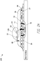
- FIG. 2A illustrates a side view of a negative pressure therapy system 200
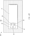
- FIG. 2B illustrates a top view of the negative pressure therapy system 200
- the negative pressure therapy system 200 can be an example implementation of the negative pressure therapy system 100.
- the wound dressing 13 of the TNP apparatus 11 is shown as attached to the wound 14. Arrows depict the flow of air through the wound dressing 13 and wound exudate from the wound 14.
- the TNP apparatus 11 can include an air exhaust 26 and a component area 25, such as a components housing or storage area for components of the TNP apparatus 11 like one or more of the control circuitry 12A, memory device 12B, negative pressure source 12C, user interface 12D, power source 12E, first pressure sensor 12F, and second pressure sensor 12G.
- the user interface 12D of the negative pressure therapy system 200 can include a switch 21 (such as a dome switch), a first indicator 23 (such as a first LED), and a second indicator 24 (such as a second LED).
- the switch 21 can receive a negative pressure activation or deactivation user input (for example, such as receiving the activation or deactivation user input in response to depression of the switch 21 for a period of time, like from between 0.5 seconds and 5 seconds).
- the first indicator 23 and the second indicator 24 can indicate an operating status like functioning normally, under fault condition, or awaiting user input.
- the switch 21 can couple to a power supply connection of the negative pressure source 12C or the control circuitry 12A or an enable signal of the negative pressure source 12C or the control circuitry 12A to activate or deactivate supply of negative pressure or disable supply of negative pressure.
- Component parts of the wound dressing 13 of the negative pressure therapy system 200 are illustrated to include an airlock layer 27, an absorbing layer 28, and a contact layer 29.
- the airlock layer 27 can enable air flow.
- the absorbing layer 28 can absorb wound exudate.
- the contact layer 29 can be soft and include silicon and be used to couple the TNP apparatus 11 to the patient.
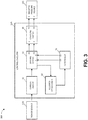
- FIG. 3 illustrates a block diagram 300 depicting example electrical communication paths between the power source 12D, control circuitry 12A, and negative pressure source 12C, as well as example components of the control circuitry 12A including a controller 31, a current limiter 32, a driving circuit 33, a feedback conditioner 34, and the coupling circuit 35.
- FIG. 3 shows, in particular, how the controller 31 can be used to control the supply of negative pressure by the negative pressure source 12C.
- the power source 12D can include one or more power supplies, such as batteries (such as, multiple 3 V batteries) or a connection to mains power, to provide power for one or more components of the TNP apparatus 11.
- the power source 12D can, for instance, provide electrical current and voltage to the current limiter 32.
- the voltage output by the power source 12D can be around 30 V, such as 29 V ⁇ 1 V, in some implementations.
- the power source 12D can additionally include circuitry, such as a boost converter, to control the electrical current and voltage provided to the current limiter 32.
- the current limiter 32 can serve to limit or clamp the current at a maximum current level, such as at 100 mA, 250 mA, 466 mA, 500 mA, or 1 A, to limit potential fault current through the driving circuit 33 and the negative pressure source 12C. Under normal operation (for example, in most or some instances), the current limiter 32 may not operate to limit current or voltage.
- the current limiter 32 can provide electric current and voltage to the driving circuit 33.
- the driving circuit 33 can include an H-bridge circuit composed of multiple switches.
- the H-bridge can be constructed to operate as an H-bridge inverter.
- the driving circuit 33 can provide feedback to the controller 31 via the feedback conditioner 34.
- the feedback conditioner 34 can be used, for instance, to condition current feedback information from the driving circuit 33 before the current feedback information is provided to the controller 31.
- the feedback conditioner 34 can include a low-pass filter (which can, for example, include active circuit components) to filter switching noise caused by the switching of one or more switches of the driving circuit 33.
- the controller 31 can, in turn, control the operations of the driving circuit 33 based on the feedback, in some instances.
- the controller 31 can control operations of the driving circuit 33, and in turn the negative pressure source 12C, by outputting one or more control signals via one or more outputs of the controller 31 to one or more inputs of the driving circuit 33.
- the controller 31 can output a first control signal via a first output O1 of the controller 31 to a first input I1 of the driving circuit 33 and a second control signal via a second output O2 of the controller 31 to a second input I2 of the driving circuit 33.
- the controller 31 can vary a pulse width modulation (PWM) of the first and second control signals to adjust an electrical current and voltage provided by the driving circuit 33 to the coupling circuit 35 and then to the negative pressure source 12C.
- PWM pulse width modulation
- the driving circuit 33 can include an H-bridge, and the controller 31 can generate the first and second control signals to cause the H-bridge to output electrical currents and voltages having a square waveform (such as about ⁇ 30 V) with a frequency (such as 18 kHz to 24 kHz or about 21 kHz) and a duty cycle or ratio (such as about 50%) via a first output O1 of the driving circuit 33 and a second output O2 of the driving circuit 33.
- a square waveform such as about ⁇ 30 V
- a frequency such as 18 kHz to 24 kHz or about 21 kHz
- a duty cycle or ratio such as about 50%
- the driving circuit 33 can control supply negative pressure by the negative pressure source 12C by providing electrical currents and voltages to the negative pressure source 12C (for example, to the actuator of the negative pressure source 12C) via the coupling circuit 35.
- the driving circuit 33 can, for instance, output electrical currents via the first and second outputs O1 and O2 of the driving circuit 33 to a first input I1 of the coupling circuit 35 and a second input I2 of the coupling circuit 35.
- the coupling circuit 35 can, in turn, output electrical currents via a first output O1 of the coupling circuit 35 and a second output O2 of the coupling circuit 35 to a first input I1 of the negative pressure source 12C and a second input I2 of the negative pressure source 12C.
- the electrical currents output by the driving circuit 33 and the coupling circuit 35 can notably be considered to result in positive charge flowing away from the driving circuit 33 (that is, sourcing of electrical current by the driving circuit 33) or toward the driving circuit 33 (that is, sinking of electrical current by the driving circuit 33).
- the coupling circuit 35 can serve to limit a rate of change over time of the current supplied by the driving circuit 33 to the negative pressure source 12C or limit a rate of change over time of a voltage across first and second inputs I1 and I2 of the negative pressure source 12C.
- the coupling circuit 35 can have an inductive reactance greater than 1 m ⁇ , 5 m ⁇ , 10 m ⁇ , 50 m ⁇ , 100 m ⁇ , 500 m ⁇ , 750 m ⁇ at an operating frequency of 1 kHz.
- the coupling circuit 35 can include passive circuit elements and not include active circuit elements, but in other embodiments, the coupling circuit 35 can include one or both of passive circuit elements and active circuit elements.
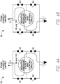
- FIGS. 4A and 4B illustrate example simplified circuit components of the driving circuit 33.
- the driving circuit 33 can be composed of at least four switches, including a first switch S1, a second switch S2, a third switch S3, and a fourth switch S4 but together form an H-bridge.
- the first and fourth switches S1 and S4 can be closed at the same time and the second and third switches S2 and S3 can be opened at the same time, as shown in FIG. 4A , to supply a first current i1 in a first direction through the coupling circuit 35 and the negative pressure source 12C.
- the second and third switches S2 and S3 can be closed at the same time and the first and fourth switches S1 and S4 can be opened at the same time, as shown in FIG. 4B , to supply a second current i2 in a second direction through the coupling circuit 35 and the negative pressure source 12C.
- the first direction can be opposite the second direction.
- FIG. 4C illustrates example circuit components of the driving circuit 33 (an H-bridge in the illustrated example) that include a resistor 42.
- the electrical current that travels through the resistor 42 can be the same or substantially the same as the electrical current that travels through the coupling circuit 35 and the negative pressure source 12C (for example, the actuator of the negative pressure source 12C).
- a feedback provided to the feedback conditioner 34 can, for instance, be a voltage level or drop across the resistor 42, which can be proportional to the electrical current that travels through the resistor 42, as well as the electrical current that travels through the coupling circuit 35 and the negative pressure source 12C.
- Resistor 42 thus can be used to measure one or more properties of the electrical current, such as a magnitude, that is fed to the negative pressure source 12C via the coupling circuit 35, such as via an inductor of the coupling circuit 35 like an inductor 52 described with respect to FIG. 5 .
- the resistor 42 can be coupled to a low-pass filter, as described herein.
- FIG. 5 illustrates example circuit components of the coupling circuit 35.
- the coupling circuit 35 can include the inductor 52 electrically coupled in series between the first output O1 of the driving circuit 33 and the first input I1 of the negative pressure source 12C, and a wire or an electrical short 54 electrically coupled in series between the second output O2 of the driving circuit 33 and the second input I2 of the negative pressure source 12C.
- the inductor 52 can have an inductance ranging from 0.1 ⁇ H to 1000 ⁇ H, 1 ⁇ H to 100 ⁇ H, or 3 ⁇ H to 10 ⁇ H, or an inductance of about 7.5 ⁇ H.
- the inductor 52 can have a maximum current rating of greater than 0.25 A, 0.5 A, 0.75 A, 1 A, or 1.25 A.
- the inductor 52 can be used to oppose rapid changes in a voltage or current supplied to drive the negative pressure source 12C.
- the coupling circuit 35 can include a first wire or a first electrical short electrically coupled in series between the first output O1 of the driving circuit 33 and the first input I1 of the negative pressure source 12C, and a second wire or a second electrical short electrically coupled in series between the second output O2 of the driving circuit 33 and the second input I2 of the negative pressure source 12C.
- the coupling circuit 35 can include a first wire or a first electrical short electrically coupled in series between the first output O1 of the driving circuit 33 and the first input I1 of the negative pressure source 12C, and an inductor (such as the inductor 52) electrically coupled in series between the second output O2 of the driving circuit 33 and the second input I2 of the negative pressure source 12C.
- the coupling circuit 35 can include a first inductor (such as the inductor 52) electrically coupled in series between the first output O1 of the driving circuit 33 and the first input I1 of the negative pressure source 12C, and a second inductor (such as the inductor 52) electrically coupled in series between the second output O2 of the driving circuit 33 and the second input I2 of the negative pressure source 12C.
- a first inductor such as the inductor 52
- a second inductor such as the inductor 52
- one or more active elements can be used in place of or in addition to one or more inductors.
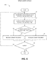
- FIG. 6 illustrates a therapy control process 600 performable by an apparatus, such as the TNP apparatus 11.
- the therapy control process 600 is described in the context of the TNP apparatus 11, but may instead be implemented in other systems described herein or by other computing systems not shown.
- the therapy control process 600 can be an iterative process by which a TNP apparatus tunes the transfer of power (for example, by adjusting parameters of a driving signal) to a negative pressure source to maximize an amount of power transferred to the negative pressure source and thereby improve the efficiency (which, for example, can be measured by a more efficient power consumption).
- the therapy control process 600 may begin within a period of time after startup of the TNP apparatus, such as within 0.001, 0.01, 0.1, 0.5, 1, 2, or 5 minutes of starting supply of pressure with the negative pressure source.
- the therapy control process 600 can initiate with a particular driving signal energy having an initial magnitude and an initial frequency (for example, an electrical current having an initial current magnitude and an initial current frequency) already being provided to negative pressure source.
- the initial frequency can be less than or greater than a mechanical resonant frequency (for example, which can be 1, 5, 10, 25, 50, 100, 200, 500, and 1000 kHz) of the negative pressure source.
- the therapy control process 600 can determine a current magnitude of an electrical current at a previous time and at a next time.
- the controller 31 can determine a current magnitude of an electrical current supplied by the driving circuit 33 to the coupling circuit 35 and the negative pressure source 12C at a previous time and at a next time.
- the previous time can be a time prior to the next time.
- the previous time can, for instance, be a time during an immediately previous iteration to the next time or a time during two or more iterations previous to the next time.
- the controller 31 can determine the current magnitude (or a value indicative thereof) from the feedback provided by the feedback conditioner 34.
- the therapy control process 600 can compare the current magnitude at the previous time and the next time.
- the controller 31 can compare the current magnitude of the electrical current supplied by the driving circuit 33 at the previous time and the current magnitude of the electrical current supplied by the driving circuit 33 at the next time.
- the therapy control process 600 can determine if the current magnitude at the previous time is less than at the next time. For example, the controller 31 can determine if the current magnitude of the electrical current supplied by the driving circuit 33 at the previous time is less than the current magnitude of the electrical current supplied by the driving circuit 33 at the next time.
- the therapy control process 600 can at block 64 increase a current frequency of the electrical current.
- the controller 31 can increase the frequency of the electrical current supplied by the driving circuit 33 by an increase amount (for example, 1, 3, 5, 10, 30, 50, 70, 100, 200, 300, 500, 700, 850, 1000, 2000, or 5000 Hz).
- the therapy control process 600 can at block 65 decrease a current frequency of the electrical current.
- the controller 31 can at block 65 decrease the frequency of the electrical current supplied by the driving circuit 33 by a decrease amount (for example, 1, 3, 5, 10, 30, 50, 70, 100, 200, 300, 500, 700, 850, 1000, 2000, or 5000 Hz).
- the increase amount and decrease amount can be the same or different from one another in some instances or implementations. Moreover, the increase amount or decrease amount can vary over time or be constant for a period of time (for example, 1, 3, 10, 30, or 60 seconds or 1, 3, 5, 10, or 30 minutes).
- the therapy control process 600 can determine whether to return to block 61 or end.
- the controller 31 can determine whether to repeat the therapy control process 600, such as by repeating the therapy control process 600 with a repeat frequency (for example, that may be 0.01, 0.03, 0.1, 0.3, 0.5, 1, 3, 5, 10, 30, 50, 100, 300, 500, 1000, 3000, or 5000 Hz and vary or be constant over a period of time, such as 1, 3, 10, 30, or 60 seconds or 1, 3, 5, 10, or 30 minutes) or in response to a triggering event (such as a detected change in temperate of the TNP apparatus measured by a temperature sensor).
- a repeat frequency for example, that may be 0.01, 0.03, 0.1, 0.3, 0.5, 1, 3, 5, 10, 30, 50, 100, 300, 500, 1000, 3000, or 5000 Hz and vary or be constant over a period of time, such as 1, 3, 10, 30, or 60 seconds or 1, 3, 5, 10, or 30 minutes
- a triggering event such as a detected change in temperate of the TNP apparatus
- a mechanical resonant frequency of the negative pressure source can be "searched" (for instance, continuously or periodically) during provision of therapy by attempting to adjust the initial frequency to more closely match the mechanical resonant frequency.
- the mechanical resonant frequency thus may not be known in advance of operating the TNP apparatus or known with a high precision or accuracy, and yet the frequency of the energy provided to the negative pressure source can be made to substantially match the mechanical resonant frequency.
- the frequency of the energy provided to the negative pressure source can be made to follow the mechanical resonant frequency as the mechanical resonant frequency may change due to the changing operating conditions, which in the case of the negative pressure source being mounted on or within the wound dressing can include a changing temperature, duration of operation, humidity, or the like.
- an apparatus for applying negative pressure to a wound includes a source of negative pressure, a driving circuit, a sensor, and a controller.
- the source of negative pressure can provide negative pressure via a fluid flow path to a wound dressing placed over the wound.
- the driving circuit can supply an electrical current to the source of negative pressure to cause the source of negative pressure to provide negative pressure.
- the electrical current can have a current magnitude and a current frequency.
- the sensor can detect the current magnitude.
- the controller can, while the source of negative pressure is providing negative pressure to the wound dressing, iteratively and at a first operating frequency: determine the current magnitude detected at a previous time and the current magnitude detected at a next time subsequent to the previous time; compare the current magnitude detected at the previous time and the current magnitude detected at the next time; in response to the current magnitude detected at the previous time being less than the current magnitude detected at the next time, operate the driving circuit to increase (or decrease) the current frequency; and in response to the current magnitude detected at the previous time being greater than the current magnitude detected at the next time, operate the driving circuit to decrease (or increase) the current frequency.
- the apparatus of the preceding paragraph can include one or more of the following features:
- the controller can operate the driving circuit so that the current frequency matches an initial frequency when the driving circuit activates the source of negative pressure to begin providing negative pressure, and the controller can operate the driving circuit to increase or decrease the current frequency within a first period of time from the driving circuit activating the source of negative pressure.
- the source of negative pressure can have a mechanical resonance frequency, and the mechanical resonance frequency can be greater than the initial frequency.
- the source of negative pressure can have a mechanical resonance frequency, and the mechanical resonance frequency can be less than the initial frequency.
- the source of negative pressure can have a mechanical resonance frequency with one or more subharmonic or harmonic frequencies
- the controller can operate the driving circuit to increase or decrease the current frequency so that the current frequency is not one of the one or more subharmonic or harmonic frequencies or remains outside of one or more frequency ranges that include the one or more subharmonic or harmonic frequencies.
- the mechanical resonance frequency can be between 5 KHz and 100 kHz, such as around 20 KHz, 22 kHz, or 24 kHz or greater or less than 5 KHz and 100 kHz.
- the first period of time can be between 1 msec and 1 min, such as around 1 msec, 10 msec, 100 msec, or 1 sec or greater or less than 1 msec and 1 min.
- the current magnitude detected at the next time in a first iteration is the current magnitude detected at the previous time in a second iteration subsequent to the first iteration.
- the first iteration and the second iteration may not be separated by another iteration.
- the controller can: operate the driving circuit to increase the current frequency by a first amount; and operate the driving circuit to decrease the current frequency by a second amount.
- the first amount can be the same as the second amount.
- the first amount can be different from the second amount.
- the first amount or the second amount can vary over time.
- the first amount or the second amount can be constant over a second period of time while the source of negative pressure is providing negative pressure to the wound dressing.
- the second period of time can be between 10 sec and 10 min, such as around 10 sec, 1 min, or 10 min or greater or less than 10 sec and 10 min.
- the first amount or the second amount can be between 1 Hz and 1000 Hz, such as around 1 Hz, 10 Hz, 100 Hz, or 1000 Hz or greater or less than 1 Hz and 1000 Hz.
- the first operating frequency can vary over time.
- the first operating frequency can be constant over a third period of time while the source of negative pressure is providing negative pressure to the wound dressing.
- the third period of time can be between 10 sec and 10 min, such as around 10 sec, 1 min, or 10 min or greater or less than 10 sec and 10 min.
- the first operating frequency can be between 0.1 Hz and 100 Hz, such as around 0.1 Hz, 1 Hz, 10 Hz, or 100 Hz or greater or less than 0.1 Hz and 100 Hz.
- the source of negative pressure can include a piezoelectric pump.
- the source of negative pressure can be a micropump.
- the source of negative pressure can be disposed on or within the wound dressing.
- the driving circuit can include an H-bridge.
- the controller can provide a control signal to the driving circuit, and the controller can control the electrical current supplied by the driving circuit by adjusting a pulse width modulation of the control signal.
- the driving circuit can supply an electrical voltage across input terminals of the source of negative pressure via the coupling circuit, and the electrical voltage can range from greater than -50 V to less than +50 V.
- any value of a threshold, limit, duration, etc. provided herein is not intended to be absolute and, thereby, can be approximate.
- any threshold, limit, duration, etc. provided herein can be fixed or varied either automatically or by a user.
- relative terminology such as exceeds, greater than, less than, etc. in relation to a reference value is intended to also encompass being equal to the reference value. For example, exceeding a reference value that is positive can encompass being equal to or greater than the reference value.
- relative terminology such as exceeds, greater than, less than, etc. in relation to a reference value is intended to also encompass an inverse of the disclosed relationship, such as below, less than, greater than, etc. in relations to the reference value.
- blocks of the various processes may be described in terms of determining whether a value meets or does not meet a particular threshold, the blocks can be similarly understood, for example, in terms of a value (i) being below or above a threshold or (ii) satisfying or not satisfying a threshold.
- the various components illustrated in the figures may be implemented as software or firmware on a processor, controller, ASIC, FPGA, or dedicated hardware.
- Hardware components such as processors, ASICs, FPGAs, and the like, can include logic circuitry.
- User interface screens illustrated and described herein can include additional or alternative components. These components can include menus, lists, buttons, text boxes, labels, radio buttons, scroll bars, sliders, checkboxes, combo boxes, status bars, dialog boxes, windows, and the like. User interface screens can include additional or alternative information. Components can be arranged, grouped, displayed in any suitable order.
- the term "or” is used in its inclusive sense (and not in its exclusive sense) so that when used, for example, to connect a list of elements, the term “or” means one, some, or all of the elements in the list.
- the term “each,” as used herein, in addition to having its ordinary meaning, can mean any subset of a set of elements to which the term “each” is applied.
- the terms “generally parallel” and “substantially parallel” refer to a value, amount, or characteristic that departs from exactly parallel by less than or equal to 15 degrees, 10 degrees, 5 degrees, 3 degrees, 1 degree, or 0.1 degree.
Description
- This application claims the benefit of
U.S. Provisional Application No. 62/331,098, filed May 3, 2016 U.S. Provisional Application No. 62/479,588 - Embodiments of the present disclosure relate to methods and apparatuses for dressing and treating a wound with negative or reduced pressure therapy or topical negative pressure (TNP) therapy (e.g.
US 2003/040687 A1 ). In particular, but without limitation, embodiments disclosed herein relate to negative pressure therapy devices, methods (not claimed) for controlling the operation of TNP systems, and methods (not claimed) of using TNP systems. - The invention is defined in the appended claims. An apparatus for applying negative pressure to a wound, the apparatus includes a source of negative pressure, a driving circuit, and a controller. The source of negative pressure is configured to provide negative pressure via a fluid flow path to a wound dressing. The driving circuit supplies a driving signal to the source of negative pressure to cause the source of negative pressure to provide negative pressure. The driving signal has a driving signal magnitude and a driving signal frequency. The controller is configured to, while the source of negative pressure is maintaining negative pressure under the wound dressing within a pressure range, iteratively and at an operating frequency: determine the driving signal magnitude detected at a first time and the driving signal magnitude detected at a second time subsequent to the first time, compare the driving signal magnitude detected at the first time and the driving signal magnitude detected at the second time, in response to the driving signal magnitude detected at the first time being less than the driving signal magnitude detected at the second time, operate the driving circuit to increase the driving signal frequency, and in response to the driving signal magnitude detected at the first time being greater than the driving signal magnitude detected at the second time, operate the driving circuit to decrease the driving signal frequency.
- The apparatus of the preceding paragraph can include one or more of the following features: The controller can to operate the driving circuit so that the driving signal frequency matches an initial frequency when the driving circuit activates the source of negative pressure to begin providing negative pressure, and the controller can operate the driving circuit to increase or decrease the driving signal frequency within a first period of time following the driving circuit activating the source of negative pressure. The source of negative pressure can have a mechanical resonance frequency, and the mechanical resonance frequency can be greater than the initial frequency. The source of negative pressure can have a mechanical resonance frequency, and the mechanical resonance frequency can be less than the initial frequency. The mechanical resonance frequency can be between 5 kHz and 100 kHz. The first period of time can be between 1 msec and 1 min. The driving signal magnitude detected at the second time in a first iteration can be used as the driving signal magnitude detected at the first time in a second iteration subsequent to the first iteration. The first iteration and the second iteration may not be separated by another iteration. The controller can: operate the driving circuit to increase the driving signal frequency by a first amount; and operate the driving circuit to decrease the driving signal frequency by a second amount. The first amount can be the same as the second amount. The first amount can be different from the second amount. The first amount or the second amount can vary over time. The first amount or the second amount can be constant over a second period of time while the source of negative pressure is maintaining negative pressure under the wound dressing within the pressure range. The second period of time can be between 10 sec and 10 min. The first amount or the second amount can be between 1 Hz and 1000 Hz. The operating frequency can vary over time. The operating frequency can be constant over a third period of time while the source of negative pressure is maintaining negative pressure under the wound dressing within the pressure range. The third period of time can be between 10 sec and 10 min. The operating frequency can be between 0.1 Hz and 100 Hz. The source of negative pressure can include a piezoelectric pump. The source of negative pressure can include a micropump. The source of negative pressure can perform negative pressure wound therapy when negative pressure under the wound dressing is maintained within the pressure range. The apparatus can further include the wound dressing, and the source of negative pressure can be disposed on or within the wound dressing. The driving circuit can include an H-bridge circuit. The controller can further provide a control signal to the driving circuit, and the controller can control the driving signal by adjusting a pulse width modulation of the control signal. The driving circuit can supply the driving signal by supplying an electrical voltage across input terminals of the source of negative pressure via the coupling circuit, and the electrical voltage can range from greater than -50 V to less than +50 V. The driving signal can include an electrical current.
- A method (not claimed) of operating, using, or manufacturing the apparatus of the preceding two paragraphs is also disclosed.
- In some embodiments, a method (not claimed) of operating a negative pressure wound therapy apparatus is disclosed. The method can include: supplying a driving signal at a first time and at a second time to a source of negative pressure, the driving signal having a driving signal magnitude and a driving signal frequency, the second time being subsequent to the first time; providing negative pressure via a fluid flow path to a wound dressing with the source of negative pressure responsive to the driving signal; determining the driving signal magnitude at the first time and the driving signal magnitude at the second time; comparing the driving signal magnitude at the first time and the driving signal magnitude at the second time; in response to the driving signal magnitude at the first time being less than the driving signal magnitude at the second time, increasing the driving signal frequency supplied to the source of negative pressure; and in response to the driving signal magnitude at the first time being greater than the driving signal magnitude at the second time, decreasing the driving signal frequency supplied to the source of negative pressure.
- The method of the preceding paragraph can include one or more of the following features: The increasing the driving signal frequency can include increasing the driving signal frequency by a first amount; and the decreasing the driving signal frequency can include decreasing the driving signal frequency by a second amount. The first amount can be the same as the second amount. The first amount can be different from the second amount. The first amount or the second amount can be between 1 Hz and 1000 Hz. The source of negative pressure can include a piezoelectric pump. The source of negative pressure can include a micropump. The driving signal can include an electrical current.
- Features and advantages of the present disclosure will be apparent from the following detailed description, taken in conjunction with the accompanying drawings of which:
-
FIG. 1 illustrates a negative pressure therapy system according to some embodiments. -
FIGS. 2A and2B respectively illustrate a side view and top view of a negative pressure therapy system according to some embodiments, such as the negative pressure therapy system ofFIG. 1 . -
FIG. 3 illustrates a block diagram of electrical communication paths between a power source, control circuitry, and negative pressure source, as well as components of the control circuitry, according to some embodiments. -
FIGS. 4A and 4B illustrate simplified circuit components of a driving circuit according to some embodiments. -
FIG. 4C illustrates circuit components of a driving circuit according to some embodiments. -
FIG. 5 illustrates circuit components of a coupling circuit according to some embodiments. -
FIG. 6 illustrates a therapy control process performable by a negative pressure therapy system according to some embodiments. - The present disclosure relates to methods and apparatuses for dressing and treating a wound with reduced pressure therapy or topical negative pressure (TNP) therapy. In particular, but without limitation, embodiments of this disclosure relate to negative pressure therapy apparatuses, methods for controlling the operation of TNP systems, and methods of using TNP systems. The methods and apparatuses can incorporate or implement any combination of the features described below.
- Many different types of wound dressings are known for aiding in the healing process of a human or animal. These different types of wound dressings include many different types of materials and layers, for example, gauze, pads, foam pads or multi-layer wound dressings. TNP therapy, sometimes referred to as vacuum assisted closure, negative pressure wound therapy, or reduced pressure wound therapy, can be a beneficial mechanism for improving the healing rate of a wound. Such therapy is applicable to a broad range of wounds such as incisional wounds, open wounds and abdominal wounds or the like.
- TNP therapy can assist in the closure and healing of wounds by reducing tissue oedema, encouraging blood flow, stimulating the formation of granulation tissue, removing excess exudates, and reducing bacterial load and thus, infection to the wound. Furthermore, TNP therapy can permit less outside disturbance of the wound and promote more rapid healing.
- As is used herein, reduced or negative pressure levels, such as -X mmHg, represent pressure levels that are below atmospheric pressure, which typically corresponds to 760 mmHg (or 1 atm, 29.93 inHg, 101.325 kPa, 14.696 psi, etc.). Accordingly, a negative pressure value of -X mmHg reflects pressure that is X mmHg below atmospheric pressure, such as a pressure of (760-X) mmHg. In addition, negative pressure that is "less" or "smaller" than -X mmHg corresponds to pressure that is closer to atmospheric pressure (e.g., -40 mmHg is less than -60 mmHg). Negative pressure that is "more" or "greater" than -X mmHg corresponds to pressure that is further from atmospheric pressure (e.g., -80 mmHg is more than -60 mmHg).
- Control circuitry of a TNP apparatus can supply a driving signal (for example, an electrical current) to a negative pressure source and vary a frequency of the driving signal (for instance, an AC waveform frequency of the electrical current). By varying the frequency over time (for example, to match a mechanical resonance frequency of a piezoelectric pump of the negative pressure source), the control circuitry can tune the transfer of power to the negative pressure source to maximize an amount of power transferred to the negative pressure source. As a result, the TNP apparatus can automatically accommodate for component variances attributable to, for example, operating temperatures or manufacturing differences and operate the negative pressure source at an optimum or near optimum power level. In some implementations, the resonance frequency of the negative pressure source can vary in response to, for example, variations in temperature, humidity, and the like.
-
FIG. 1 illustrates a negativepressure therapy system 100 that includes aTNP apparatus 11 and awound 14. TheTNP apparatus 11 can be used to treat thewound 14. TheTNP apparatus 11 can includecontrol circuitry 12A,memory 12B, anegative pressure source 12C, auser interface 12D, apower source 12E, afirst pressure sensor 12F, and asecond pressure sensor 12G that are configured to electrically communicate with one another. In addition, theTNP apparatus 11 can include a wound dressing 13. Thepower source 12E can provide power to one or more components of theTNP apparatus 11. - One or more of the
control circuitry 12A,memory device 12B,negative pressure source 12C,user interface 12D,power source 12E,first pressure sensor 12F, andsecond pressure sensor 12G can be integral with, incorporated as part of, attached to, or disposed in the wound dressing 13. TheTNP apparatus 11 can accordingly be considered to have its control electronics and pump on-board the wound dressing 13 rather than separate from the wound dressing 13. - The
control circuitry 12A can include one or more controllers (for example, a microcontroller or microprocessor), activation circuits, boost converters, current limiters, feedback conditioning circuits, and H-bridge inverters. Thecontrol circuitry 12A can control the operations of one or more other components of theTNP apparatus 11 according at least to instructions stored in thememory device 12B. Thecontrol circuitry 12A can, for instance, control operations of and supply of negative pressure by thenegative pressure source 12C. - The
negative pressure source 12C can include a pump, such as, without limitation, a rotary diaphragm pump or other diaphragm pump, a piezoelectric pump, a peristaltic pump, a piston pump, a rotary vane pump, a liquid ring pump, a scroll pump, a pump operated by a piezoelectric transducer, or any other suitable pump or micropump or any combinations of the foregoing. The pump can include an actuator driven by a source of energy, such as electrical energy, mechanical energy, and the like. For example, the actuator can be an electric motor, a piezoelectric transducer, a voice coil actuator, an electroactive polymer, a shape-memory alloy, a comb drive, a hydraulic motor, a pneumatic actuator, a screw jack, a servomechanism, a solenoid actuator, a stepper motor, a plunger, a combustion engine, and the like. In some embodiments, thenegative pressure source 12C can supply negative pressure by converting electrical energy to mechanical energy without converting the electrical energy to magnetic energy. In such embodiments, the pump can have a different impact when electrically coupled to one or more other components of thecontrol circuitry 12A than if thenegative pressure source 12C supplied negative pressure by converting the electrical energy to the magnetic energy and then to the mechanical energy. - The
user interface 12D can include one or more elements that receive user inputs or provide user outputs to a patient or caregiver. The one or more elements that receive user inputs can include buttons, switches, dials, touch screens, or the like, and the one or more elements that provide user outputs can include activation of a light emitting diode (LED) or one or more pixels of the display or activation of a speaker or the like. In one example, theuser interface 12D can include a switch to receive user inputs (for instance, a negative pressure activation or deactivation input) and two LEDs to indicate an operating status (for example, functioning normally, under fault condition, or awaiting user input) of theTNP apparatus 11. - The
first pressure sensor 12F can be used to monitor pressure underneath the wound dressing 13, such as pressure in a fluid flow path connecting thenegative pressure source 12C and thewound 14, pressure at thewound 14, or pressure in thenegative pressure source 12C. Thesecond pressure sensor 12G can be used to monitor pressure external to the wound dressing 13. The pressure external to the wound dressing can be atmospheric pressure; however, the atmospheric pressure can vary depending on, for instance, an altitude of use or pressurized environment in which theTNP apparatus 11 may be used. - The
control circuitry 12A can control the supply of negative pressure by thenegative pressure source 12C according at least to a comparison between the pressure monitored by thefirst pressure sensor 12F and the pressure monitored by thesecond pressure sensor 12G. - The wound dressing 13 can include a wound contact layer, a spacer layer, and an absorbent layer. The wound contact layer can be in contact with the
wound 14. The wound contact layer can include an adhesive on the patient facing side for securing the dressing to the skin surrounding thewound 14 or on the top side for securing the wound contact layer to a cover layer or other layer of the wound dressing 13. In operation, the wound contact layer can provide unidirectional flow so as to facilitate removal of exudate from the wound while blocking or substantially preventing exudate from returning to thewound 14. The spacer layer can assist in distributing negative pressure over the wound site and facilitating transport of wound exudate and fluids into the wound dressing 13. Further, the absorbent layer can absorb and retain exudate aspirated from thewound 14. - The
control circuitry 12A can monitor the activity of thenegative pressure source 12C, which may include monitoring a duty cycle of thenegative pressure source 12C (for example, the duty cycle of the actuator of the negative pressure source). As is used herein, the "duty cycle" can reflect the amount of time thenegative pressure source 12C is active or running over a period of time. In other words, the duty cycle can reflect time that thenegative pressure source 12C is in an active state as a fraction of total time under consideration. Duty cycle measurements can reflect a level of activity of thenegative pressure source 12C. For example, the duty cycle can indicate that thenegative pressure source 12C is operating normally, working hard, working extremely hard, etc. Moreover, the duty cycle measurements, such as periodic duty cycle measurements, can reflect various operating conditions, such as presence or severity of leaks, rate of flow of fluid (for instance, air, liquid, or solid exudate, etc.) aspirated from a wound, or the like. Based on the duty cycle measurements, such as by comparing the measured duty cycle with a set of thresholds (for instance, determined in calibration), the controller can execute or be programmed to execute algorithms or logic that control the operation of the system. For example, duty cycle measurements can indicate presence of a high leak, and thecontrol circuitry 12A can be programmed to indicate this condition to a user (for instance, patient, caregiver, or physician) or temporarily suspend or pause operation of the source of negative pressure in order to conserve power. - When the
TNP apparatus 11 may be used to treat thewound 14, the wound dressing 13 can create a substantially sealed or closed space around thewound 13 and under the wound dressing 13, and thefirst pressure sensor 12F can periodically or continuously measure or monitor a level of pressure in this space. Thecontrol circuitry 12A can control the level of pressure in the space between a first negative pressure set point limit and at least a second negative pressure set point limit. In some instances, the first set point limit can be approximately ―70 mmHg, or from approximately ―60 mmHg or less to approximately -80 mmHg or more. In some instances, the second set point limit can be approximately -90 mmHg, or from approximately ―80 mmHg or less to approximately -100 mmHg or more. -
FIG. 2A illustrates a side view of a negativepressure therapy system 200, andFIG. 2B illustrates a top view of the negativepressure therapy system 200. The negativepressure therapy system 200 can be an example implementation of the negativepressure therapy system 100. - In the negative
pressure therapy system 200, the wound dressing 13 of theTNP apparatus 11 is shown as attached to thewound 14. Arrows depict the flow of air through the wound dressing 13 and wound exudate from thewound 14. TheTNP apparatus 11 can include anair exhaust 26 and acomponent area 25, such as a components housing or storage area for components of theTNP apparatus 11 like one or more of thecontrol circuitry 12A,memory device 12B,negative pressure source 12C,user interface 12D,power source 12E,first pressure sensor 12F, andsecond pressure sensor 12G. - The
user interface 12D of the negativepressure therapy system 200 can include a switch 21 (such as a dome switch), a first indicator 23 (such as a first LED), and a second indicator 24 (such as a second LED). Theswitch 21 can receive a negative pressure activation or deactivation user input (for example, such as receiving the activation or deactivation user input in response to depression of theswitch 21 for a period of time, like from between 0.5 seconds and 5 seconds). Thefirst indicator 23 and thesecond indicator 24 can indicate an operating status like functioning normally, under fault condition, or awaiting user input. In some implementations, theswitch 21 can couple to a power supply connection of thenegative pressure source 12C or thecontrol circuitry 12A or an enable signal of thenegative pressure source 12C or thecontrol circuitry 12A to activate or deactivate supply of negative pressure or disable supply of negative pressure. - Component parts of the wound dressing 13 of the negative
pressure therapy system 200 are illustrated to include anairlock layer 27, an absorbinglayer 28, and acontact layer 29. Theairlock layer 27 can enable air flow. The absorbinglayer 28 can absorb wound exudate. Thecontact layer 29 can be soft and include silicon and be used to couple theTNP apparatus 11 to the patient. -
FIG. 3 illustrates a block diagram 300 depicting example electrical communication paths between thepower source 12D,control circuitry 12A, andnegative pressure source 12C, as well as example components of thecontrol circuitry 12A including acontroller 31, acurrent limiter 32, a drivingcircuit 33, afeedback conditioner 34, and thecoupling circuit 35.FIG. 3 shows, in particular, how thecontroller 31 can be used to control the supply of negative pressure by thenegative pressure source 12C. - The
power source 12D can include one or more power supplies, such as batteries (such as, multiple 3 V batteries) or a connection to mains power, to provide power for one or more components of theTNP apparatus 11. Thepower source 12D can, for instance, provide electrical current and voltage to thecurrent limiter 32. The voltage output by thepower source 12D can be around 30 V, such as 29 V ± 1 V, in some implementations. Thepower source 12D can additionally include circuitry, such as a boost converter, to control the electrical current and voltage provided to thecurrent limiter 32. - The
current limiter 32 can serve to limit or clamp the current at a maximum current level, such as at 100 mA, 250 mA, 466 mA, 500 mA, or 1 A, to limit potential fault current through the drivingcircuit 33 and thenegative pressure source 12C. Under normal operation (for example, in most or some instances), thecurrent limiter 32 may not operate to limit current or voltage. - The
current limiter 32 can provide electric current and voltage to the drivingcircuit 33. The drivingcircuit 33 can include an H-bridge circuit composed of multiple switches. The H-bridge can be constructed to operate as an H-bridge inverter. The drivingcircuit 33 can provide feedback to thecontroller 31 via thefeedback conditioner 34. Thefeedback conditioner 34 can be used, for instance, to condition current feedback information from the drivingcircuit 33 before the current feedback information is provided to thecontroller 31. In one example, thefeedback conditioner 34 can include a low-pass filter (which can, for example, include active circuit components) to filter switching noise caused by the switching of one or more switches of the drivingcircuit 33. Thecontroller 31 can, in turn, control the operations of the drivingcircuit 33 based on the feedback, in some instances. - The
controller 31 can control operations of the drivingcircuit 33, and in turn thenegative pressure source 12C, by outputting one or more control signals via one or more outputs of thecontroller 31 to one or more inputs of the drivingcircuit 33. For example, thecontroller 31 can output a first control signal via a first output O1 of thecontroller 31 to a first input I1 of the drivingcircuit 33 and a second control signal via a second output O2 of thecontroller 31 to a second input I2 of the drivingcircuit 33. Thecontroller 31 can vary a pulse width modulation (PWM) of the first and second control signals to adjust an electrical current and voltage provided by the drivingcircuit 33 to thecoupling circuit 35 and then to thenegative pressure source 12C. In one implementation, the drivingcircuit 33 can include an H-bridge, and thecontroller 31 can generate the first and second control signals to cause the H-bridge to output electrical currents and voltages having a square waveform (such as about ± 30 V) with a frequency (such as 18 kHz to 24 kHz or about 21 kHz) and a duty cycle or ratio (such as about 50%) via a first output O1 of the drivingcircuit 33 and a second output O2 of the drivingcircuit 33. - The driving
circuit 33 can control supply negative pressure by thenegative pressure source 12C by providing electrical currents and voltages to thenegative pressure source 12C (for example, to the actuator of thenegative pressure source 12C) via thecoupling circuit 35. The drivingcircuit 33 can, for instance, output electrical currents via the first and second outputs O1 and O2 of the drivingcircuit 33 to a first input I1 of thecoupling circuit 35 and a second input I2 of thecoupling circuit 35. Thecoupling circuit 35 can, in turn, output electrical currents via a first output O1 of thecoupling circuit 35 and a second output O2 of thecoupling circuit 35 to a first input I1 of thenegative pressure source 12C and a second input I2 of thenegative pressure source 12C. The electrical currents output by the drivingcircuit 33 and thecoupling circuit 35 can notably be considered to result in positive charge flowing away from the driving circuit 33 (that is, sourcing of electrical current by the driving circuit 33) or toward the driving circuit 33 (that is, sinking of electrical current by the driving circuit 33). - The
coupling circuit 35 can serve to limit a rate of change over time of the current supplied by the drivingcircuit 33 to thenegative pressure source 12C or limit a rate of change over time of a voltage across first and second inputs I1 and I2 of thenegative pressure source 12C. Thecoupling circuit 35 can have an inductive reactance greater than 1 mΩ, 5 mΩ, 10 mΩ, 50 mΩ, 100 mΩ, 500 mΩ, 750 mΩ at an operating frequency of 1 kHz. In some embodiments, thecoupling circuit 35 can include passive circuit elements and not include active circuit elements, but in other embodiments, thecoupling circuit 35 can include one or both of passive circuit elements and active circuit elements. -
FIGS. 4A and 4B illustrate example simplified circuit components of the drivingcircuit 33. As can be seen fromFIGS. 4A and 4B , the drivingcircuit 33 can be composed of at least four switches, including a first switch S1, a second switch S2, a third switch S3, and a fourth switch S4 but together form an H-bridge. The first and fourth switches S1 and S4 can be closed at the same time and the second and third switches S2 and S3 can be opened at the same time, as shown inFIG. 4A , to supply a first current i1 in a first direction through thecoupling circuit 35 and thenegative pressure source 12C. The second and third switches S2 and S3 can be closed at the same time and the first and fourth switches S1 and S4 can be opened at the same time, as shown inFIG. 4B , to supply a second current i2 in a second direction through thecoupling circuit 35 and thenegative pressure source 12C. The first direction can be opposite the second direction. -
FIG. 4C illustrates example circuit components of the driving circuit 33 (an H-bridge in the illustrated example) that include aresistor 42. In the example circuit components shown inFIG. 4C , the electrical current that travels through theresistor 42 can be the same or substantially the same as the electrical current that travels through thecoupling circuit 35 and thenegative pressure source 12C (for example, the actuator of thenegative pressure source 12C). As a result, a feedback provided to thefeedback conditioner 34 can, for instance, be a voltage level or drop across theresistor 42, which can be proportional to the electrical current that travels through theresistor 42, as well as the electrical current that travels through thecoupling circuit 35 and thenegative pressure source 12C.Resistor 42 thus can be used to measure one or more properties of the electrical current, such as a magnitude, that is fed to thenegative pressure source 12C via thecoupling circuit 35, such as via an inductor of thecoupling circuit 35 like aninductor 52 described with respect toFIG. 5 . Theresistor 42 can be coupled to a low-pass filter, as described herein. -
FIG. 5 illustrates example circuit components of thecoupling circuit 35. As can be seen fromFIG. 5 , thecoupling circuit 35 can include theinductor 52 electrically coupled in series between the first output O1 of the drivingcircuit 33 and the first input I1 of thenegative pressure source 12C, and a wire or an electrical short 54 electrically coupled in series between the second output O2 of the drivingcircuit 33 and the second input I2 of thenegative pressure source 12C. Theinductor 52 can have an inductance ranging from 0.1 µH to 1000 µH, 1 µH to 100 µH, or 3 µH to 10 µH, or an inductance of about 7.5 µH. Theinductor 52 can have a maximum current rating of greater than 0.25 A, 0.5 A, 0.75 A, 1 A, or 1.25 A. Theinductor 52 can be used to oppose rapid changes in a voltage or current supplied to drive thenegative pressure source 12C. - In another embodiment, the
coupling circuit 35 can include a first wire or a first electrical short electrically coupled in series between the first output O1 of the drivingcircuit 33 and the first input I1 of thenegative pressure source 12C, and a second wire or a second electrical short electrically coupled in series between the second output O2 of the drivingcircuit 33 and the second input I2 of thenegative pressure source 12C. - In yet another embodiment, the
coupling circuit 35 can include a first wire or a first electrical short electrically coupled in series between the first output O1 of the drivingcircuit 33 and the first input I1 of thenegative pressure source 12C, and an inductor (such as the inductor 52) electrically coupled in series between the second output O2 of the drivingcircuit 33 and the second input I2 of thenegative pressure source 12C. - In yet a further embodiment, the
coupling circuit 35 can include a first inductor (such as the inductor 52) electrically coupled in series between the first output O1 of the drivingcircuit 33 and the first input I1 of thenegative pressure source 12C, and a second inductor (such as the inductor 52) electrically coupled in series between the second output O2 of the drivingcircuit 33 and the second input I2 of thenegative pressure source 12C. - In certain implementations, one or more active elements can be used in place of or in addition to one or more inductors.
-
FIG. 6 illustrates atherapy control process 600 performable by an apparatus, such as theTNP apparatus 11. For convenience, thetherapy control process 600 is described in the context of theTNP apparatus 11, but may instead be implemented in other systems described herein or by other computing systems not shown. Thetherapy control process 600 can be an iterative process by which a TNP apparatus tunes the transfer of power (for example, by adjusting parameters of a driving signal) to a negative pressure source to maximize an amount of power transferred to the negative pressure source and thereby improve the efficiency (which, for example, can be measured by a more efficient power consumption). - The
therapy control process 600 may begin within a period of time after startup of the TNP apparatus, such as within 0.001, 0.01, 0.1, 0.5, 1, 2, or 5 minutes of starting supply of pressure with the negative pressure source. Thetherapy control process 600 can initiate with a particular driving signal energy having an initial magnitude and an initial frequency (for example, an electrical current having an initial current magnitude and an initial current frequency) already being provided to negative pressure source. The initial frequency can be less than or greater than a mechanical resonant frequency (for example, which can be 1, 5, 10, 25, 50, 100, 200, 500, and 1000 kHz) of the negative pressure source. - At
block 61, thetherapy control process 600 can determine a current magnitude of an electrical current at a previous time and at a next time. For example, thecontroller 31 can determine a current magnitude of an electrical current supplied by the drivingcircuit 33 to thecoupling circuit 35 and thenegative pressure source 12C at a previous time and at a next time. The previous time can be a time prior to the next time. The previous time can, for instance, be a time during an immediately previous iteration to the next time or a time during two or more iterations previous to the next time. Thecontroller 31 can determine the current magnitude (or a value indicative thereof) from the feedback provided by thefeedback conditioner 34. - At
block 62, thetherapy control process 600 can compare the current magnitude at the previous time and the next time. For example, thecontroller 31 can compare the current magnitude of the electrical current supplied by the drivingcircuit 33 at the previous time and the current magnitude of the electrical current supplied by the drivingcircuit 33 at the next time. - At
block 63, thetherapy control process 600 can determine if the current magnitude at the previous time is less than at the next time. For example, thecontroller 31 can determine if the current magnitude of the electrical current supplied by the drivingcircuit 33 at the previous time is less than the current magnitude of the electrical current supplied by the drivingcircuit 33 at the next time. - If the result at
block 63 is yes, thetherapy control process 600 can at block 64 increase a current frequency of the electrical current. For example, thecontroller 31 can increase the frequency of the electrical current supplied by the drivingcircuit 33 by an increase amount (for example, 1, 3, 5, 10, 30, 50, 70, 100, 200, 300, 500, 700, 850, 1000, 2000, or 5000 Hz). If the result atblock 63 is no, thetherapy control process 600 can at block 65 decrease a current frequency of the electrical current. For example, thecontroller 31 can at block 65 decrease the frequency of the electrical current supplied by the drivingcircuit 33 by a decrease amount (for example, 1, 3, 5, 10, 30, 50, 70, 100, 200, 300, 500, 700, 850, 1000, 2000, or 5000 Hz). The increase amount and decrease amount can be the same or different from one another in some instances or implementations. Moreover, the increase amount or decrease amount can vary over time or be constant for a period of time (for example, 1, 3, 10, 30, or 60 seconds or 1, 3, 5, 10, or 30 minutes). - At
block 66, thetherapy control process 600 can determine whether to return to block 61 or end. For example, thecontroller 31 can determine whether to repeat thetherapy control process 600, such as by repeating thetherapy control process 600 with a repeat frequency (for example, that may be 0.01, 0.03, 0.1, 0.3, 0.5, 1, 3, 5, 10, 30, 50, 100, 300, 500, 1000, 3000, or 5000 Hz and vary or be constant over a period of time, such as 1, 3, 10, 30, or 60 seconds or 1, 3, 5, 10, or 30 minutes) or in response to a triggering event (such as a detected change in temperate of the TNP apparatus measured by a temperature sensor). - Through the
therapy control process 600, a mechanical resonant frequency of the negative pressure source can be "searched" (for instance, continuously or periodically) during provision of therapy by attempting to adjust the initial frequency to more closely match the mechanical resonant frequency. The mechanical resonant frequency thus may not be known in advance of operating the TNP apparatus or known with a high precision or accuracy, and yet the frequency of the energy provided to the negative pressure source can be made to substantially match the mechanical resonant frequency. Moreover, the frequency of the energy provided to the negative pressure source can be made to follow the mechanical resonant frequency as the mechanical resonant frequency may change due to the changing operating conditions, which in the case of the negative pressure source being mounted on or within the wound dressing can include a changing temperature, duration of operation, humidity, or the like. - In some embodiments, an apparatus for applying negative pressure to a wound includes a source of negative pressure, a driving circuit, a sensor, and a controller. The source of negative pressure can provide negative pressure via a fluid flow path to a wound dressing placed over the wound. The driving circuit can supply an electrical current to the source of negative pressure to cause the source of negative pressure to provide negative pressure. The electrical current can have a current magnitude and a current frequency. The sensor can detect the current magnitude. The controller can, while the source of negative pressure is providing negative pressure to the wound dressing, iteratively and at a first operating frequency: determine the current magnitude detected at a previous time and the current magnitude detected at a next time subsequent to the previous time; compare the current magnitude detected at the previous time and the current magnitude detected at the next time; in response to the current magnitude detected at the previous time being less than the current magnitude detected at the next time, operate the driving circuit to increase (or decrease) the current frequency; and in response to the current magnitude detected at the previous time being greater than the current magnitude detected at the next time, operate the driving circuit to decrease (or increase) the current frequency.
- The apparatus of the preceding paragraph can include one or more of the following features: The controller can operate the driving circuit so that the current frequency matches an initial frequency when the driving circuit activates the source of negative pressure to begin providing negative pressure, and the controller can operate the driving circuit to increase or decrease the current frequency within a first period of time from the driving circuit activating the source of negative pressure. The source of negative pressure can have a mechanical resonance frequency, and the mechanical resonance frequency can be greater than the initial frequency. The source of negative pressure can have a mechanical resonance frequency, and the mechanical resonance frequency can be less than the initial frequency. The source of negative pressure can have a mechanical resonance frequency with one or more subharmonic or harmonic frequencies, and the controller can operate the driving circuit to increase or decrease the current frequency so that the current frequency is not one of the one or more subharmonic or harmonic frequencies or remains outside of one or more frequency ranges that include the one or more subharmonic or harmonic frequencies. The mechanical resonance frequency can be between 5 KHz and 100 kHz, such as around 20 KHz, 22 kHz, or 24 kHz or greater or less than 5 KHz and 100 kHz. The first period of time can be between 1 msec and 1 min, such as around 1 msec, 10 msec, 100 msec, or 1 sec or greater or less than 1 msec and 1 min. The current magnitude detected at the next time in a first iteration is the current magnitude detected at the previous time in a second iteration subsequent to the first iteration. The first iteration and the second iteration may not be separated by another iteration. The controller can: operate the driving circuit to increase the current frequency by a first amount; and operate the driving circuit to decrease the current frequency by a second amount. The first amount can be the same as the second amount. The first amount can be different from the second amount. The first amount or the second amount can vary over time. The first amount or the second amount can be constant over a second period of time while the source of negative pressure is providing negative pressure to the wound dressing. The second period of time can be between 10 sec and 10 min, such as around 10 sec, 1 min, or 10 min or greater or less than 10 sec and 10 min. The first amount or the second amount can be between 1 Hz and 1000 Hz, such as around 1 Hz, 10 Hz, 100 Hz, or 1000 Hz or greater or less than 1 Hz and 1000 Hz. The first operating frequency can vary over time. The first operating frequency can be constant over a third period of time while the source of negative pressure is providing negative pressure to the wound dressing. The third period of time can be between 10 sec and 10 min, such as around 10 sec, 1 min, or 10 min or greater or less than 10 sec and 10 min. The first operating frequency can be between 0.1 Hz and 100 Hz, such as around 0.1 Hz, 1 Hz, 10 Hz, or 100 Hz or greater or less than 0.1 Hz and 100 Hz. The source of negative pressure can include a piezoelectric pump. The source of negative pressure can be a micropump. The source of negative pressure can be disposed on or within the wound dressing. The driving circuit can include an H-bridge. The controller can provide a control signal to the driving circuit, and the controller can control the electrical current supplied by the driving circuit by adjusting a pulse width modulation of the control signal. The driving circuit can supply an electrical voltage across input terminals of the source of negative pressure via the coupling circuit, and the electrical voltage can range from greater than -50 V to less than +50 V.
- Any value of a threshold, limit, duration, etc. provided herein is not intended to be absolute and, thereby, can be approximate. In addition, any threshold, limit, duration, etc. provided herein can be fixed or varied either automatically or by a user. Furthermore, as is used herein relative terminology such as exceeds, greater than, less than, etc. in relation to a reference value is intended to also encompass being equal to the reference value. For example, exceeding a reference value that is positive can encompass being equal to or greater than the reference value. In addition, as is used herein relative terminology such as exceeds, greater than, less than, etc. in relation to a reference value is intended to also encompass an inverse of the disclosed relationship, such as below, less than, greater than, etc. in relations to the reference value. Moreover, although blocks of the various processes may be described in terms of determining whether a value meets or does not meet a particular threshold, the blocks can be similarly understood, for example, in terms of a value (i) being below or above a threshold or (ii) satisfying or not satisfying a threshold.
- Features, materials, characteristics, or groups described in conjunction with a particular aspect, embodiment, or example are to be understood to be applicable to any other aspect, embodiment or example described herein unless incompatible therewith. All of the features disclosed in this specification (including any accompanying claims, abstract, and drawings), or all of the steps of any method or process so disclosed, may be combined in any combination, except combinations where at least some of such features or steps are mutually exclusive. The protection is not restricted to the details of any foregoing embodiments.
- While certain embodiments have been described, these embodiments have been presented by way of example only, and are not intended to limit the scope of protection. Indeed, the novel methods and systems described herein may be embodied in a variety of other forms. Furthermore, various omissions, substitutions and changes in the form of the methods and systems described herein may be made. Those skilled in the art will appreciate that in some embodiments, the actual steps taken in the processes illustrated or disclosed may differ from those shown in the figures. Depending on the embodiment, certain of the steps described above may be removed, others may be added. For example, the actual steps or order of steps taken in the disclosed processes may differ from those shown in the figure. Depending on the embodiment, certain of the steps described above may be removed, others may be added. For instance, the various components illustrated in the figures may be implemented as software or firmware on a processor, controller, ASIC, FPGA, or dedicated hardware. Hardware components, such as processors, ASICs, FPGAs, and the like, can include logic circuitry. Furthermore, the features and attributes of the specific embodiments disclosed above may be combined in different ways to form additional embodiments, all of which fall within the scope of the present disclosure.
- User interface screens illustrated and described herein can include additional or alternative components. These components can include menus, lists, buttons, text boxes, labels, radio buttons, scroll bars, sliders, checkboxes, combo boxes, status bars, dialog boxes, windows, and the like. User interface screens can include additional or alternative information. Components can be arranged, grouped, displayed in any suitable order.
- Although the present disclosure includes certain embodiments, examples and applications, it will be understood by those skilled in the art that the present disclosure extends beyond the specifically disclosed embodiments to other alternative embodiments or uses and obvious modifications and equivalents thereof, including embodiments which do not provide all of the features and advantages set forth herein. Accordingly, the scope of the present disclosure is not intended to be limited by the specific disclosures of preferred embodiments herein, and is defined by the appended claims.
- Conditional language, such as "can," "could," "might," or "may," unless specifically stated otherwise, or otherwise understood within the context as used, is generally intended to convey that certain embodiments include, while other embodiments do not include, certain features, elements, or steps. Thus, such conditional language is not generally intended to imply that features, elements, or steps are in any way required for one or more embodiments or that one or more embodiments necessarily include logic for deciding, with or without user input or prompting, whether these features, elements, or steps are included or are to be performed in any particular embodiment. The terms "comprising," "including," "having," and the like are synonymous and are used inclusively, in an open-ended fashion, and do not exclude additional elements, features, acts, operations, and so forth. Also, the term "or" is used in its inclusive sense (and not in its exclusive sense) so that when used, for example, to connect a list of elements, the term "or" means one, some, or all of the elements in the list. Further, the term "each," as used herein, in addition to having its ordinary meaning, can mean any subset of a set of elements to which the term "each" is applied.
- Conjunctive language such as the phrase "at least one of X, Y, and Z," unless specifically stated otherwise, is otherwise understood with the context as used in general to convey that an item, term, etc. may be either X, Y, or Z. Thus, such conjunctive language is not generally intended to imply that certain embodiments require the presence of at least one of X, at least one of Y, and at least one of Z.
- Language of degree used herein, such as the terms "approximately," "about," "generally," and "substantially" as used herein represent a value, amount, or characteristic close to the stated value, amount, or characteristic that still performs a desired function or achieves a desired result. For example, the terms "approximately", "about", "generally," and "substantially" may refer to an amount that is within less than 10% of, within less than 5% of, within less than 1% of, within less than 0.1% of, and within less than 0.01% of the stated amount. As another example, in certain embodiments, the terms "generally parallel" and "substantially parallel" refer to a value, amount, or characteristic that departs from exactly parallel by less than or equal to 15 degrees, 10 degrees, 5 degrees, 3 degrees, 1 degree, or 0.1 degree.
- The scope of the present disclosure is not intended to be limited by the specific disclosures of preferred embodiments in this section or elsewhere in this specification, and is defined by the appended claims.
Claims (15)
- An apparatus for applying negative pressure to a wound, the apparatus comprising:a source of negative pressure (12C) configured to provide negative pressure via a fluid flow path to a wound dressing (13);a driving circuit (33) configured to supply a driving signal to the source of negative pressure to cause the source of negative pressure to provide negative pressure, the driving signal having a driving signal magnitude and a driving signal frequency; and characterised bya controller (31) configured to, while the source of negative pressure is maintaining negative pressure under the wound dressing within a pressure range, iteratively and at an operating frequency:determine (61) the driving signal magnitude detected at a first time and the driving signal magnitude detected at a second time subsequent to the first time,compare (62) the driving signal magnitude detected at the first time and the driving signal magnitude detected at the second time,in response to the driving signal magnitude detected at the first time being less than the driving signal magnitude detected at the second time, operate (64) the driving circuit to increase the driving signal frequency, andin response to the driving signal magnitude detected at the first time being greater than the driving signal magnitude detected at the second time, operate (65) the driving circuit to decrease the driving signal frequency.
- The apparatus of claim 1, wherein the controller is configured to operate the driving circuit so that the driving signal frequency matches an initial frequency when the driving circuit activates the source of negative pressure to begin providing negative pressure, and the controller is configured to operate the driving circuit to increase or decrease the driving signal frequency within a first period of time following the driving circuit activating the source of negative pressure.
- The apparatus of claim 2, wherein the source of negative pressure has a mechanical resonance frequency, and the mechanical resonance frequency is greater than the initial frequency.
- The apparatus of claim 2, wherein the source of negative pressure has a mechanical resonance frequency, and the mechanical resonance frequency is less than the initial frequency.
- The apparatus of claim 4, wherein the mechanical resonance frequency is between 5 kHz and 100 kHz.
- The apparatus of claim 2, wherein the first period of time is between 1 msec and 1 min.
- The apparatus of claim 1, wherein the driving signal magnitude detected at the second time in a first iteration is used as the driving signal magnitude detected at the first time in a second iteration subsequent to the first iteration.
- The apparatus of claim 7, wherein the first iteration and the second iteration are not separated by another iteration.
- The apparatus of claim 1, wherein the controller is configured to:operate the driving circuit to increase the driving signal frequency by a first amount; andoperate the driving circuit to decrease the driving signal frequency by a second amount.
- The apparatus of claim 9, wherein the first amount is the same as the second amount.
- The apparatus of claim 9, wherein the first amount or the second amount varies over time.
- The apparatus of claim 9, wherein the first amount or the second amount is between 1 Hz and 1000 Hz.
- The apparatus of claim 1, wherein the source of negative pressure comprises a piezoelectric pump.
- The apparatus of claim 1, wherein the source of negative pressure comprises a micropump.
- The apparatus of claim 1, further comprising the wound dressing, the source of negative pressure being disposed on or within the wound dressing.
Applications Claiming Priority (3)
| Application Number | Priority Date | Filing Date | Title |
|---|---|---|---|
| US201662331098P | 2016-05-03 | 2016-05-03 | |
| US201762479588P | 2017-03-31 | 2017-03-31 | |
| PCT/EP2017/060452 WO2017191149A1 (en) | 2016-05-03 | 2017-05-03 | Optimizing power transfer to negative pressure sources in negative pressure therapy systems |
Publications (2)
| Publication Number | Publication Date |
|---|---|
| EP3452130A1 EP3452130A1 (en) | 2019-03-13 |
| EP3452130B1 true EP3452130B1 (en) | 2021-12-01 |
Family
ID=58669791
Family Applications (1)
| Application Number | Title | Priority Date | Filing Date |
|---|---|---|---|
| EP17721364.2A Active EP3452130B1 (en) | 2016-05-03 | 2017-05-03 | Optimizing power transfer to negative pressure sources in negative pressure therapy systems |
Country Status (7)
| Country | Link |
|---|---|
| US (2) | US11173240B2 (en) |
| EP (1) | EP3452130B1 (en) |
| JP (1) | JP6975170B2 (en) |
| CN (1) | CN109069710B (en) |
| AU (1) | AU2017259906B2 (en) |
| CA (1) | CA3038206A1 (en) |
| WO (1) | WO2017191149A1 (en) |
Cited By (1)
| Publication number | Priority date | Publication date | Assignee | Title |
|---|---|---|---|---|
| US11828283B2 (en) | 2020-01-29 | 2023-11-28 | Convatec Limited | Pump assembly and a wound therapy apparatus |
Families Citing this family (20)
| Publication number | Priority date | Publication date | Assignee | Title |
|---|---|---|---|---|
| JP6725528B2 (en) | 2014-12-22 | 2020-07-22 | スミス アンド ネフュー ピーエルシーSmith & Nephew Public Limited Company | Device and method for negative pressure wound therapy |
| CA3016484A1 (en) | 2016-03-07 | 2017-09-14 | Smith & Nephew Plc | Wound treatment apparatuses and methods with negative pressure source integrated into wound dressing |
| EP3448451B1 (en) | 2016-04-26 | 2021-12-08 | Smith & Nephew plc | Wound dressings and methods of use with integrated negative pressure source having a fluid ingress inhibition component |
| AU2017259003B2 (en) | 2016-05-03 | 2022-09-22 | Smith & Nephew Plc | Systems and methods for driving negative pressure sources in negative pressure therapy systems |
| EP3452129B1 (en) | 2016-05-03 | 2022-03-23 | Smith & Nephew plc | Negative pressure wound therapy device activation and control |
| JP7303104B2 (en) | 2016-08-25 | 2023-07-04 | スミス アンド ネフュー ピーエルシー | Absorbable Negative Pressure Wound Therapy Dressing |
| EP3519001A1 (en) | 2016-09-30 | 2019-08-07 | Smith & Nephew PLC | Negative pressure wound treatment apparatuses and methods with integrated electronics |
| AU2018229808B2 (en) | 2017-03-08 | 2024-04-11 | Smith & Nephew Plc | Negative pressure wound therapy device control in presence of fault condition |
| WO2018206420A1 (en) | 2017-05-09 | 2018-11-15 | Smith & Nephew Plc | Redundant controls for negative pressure wound therapy systems |
| CN111065424A (en) | 2017-09-13 | 2020-04-24 | 史密夫及内修公开有限公司 | Negative pressure wound therapy apparatus with integrated electronics and method |
| GB201718070D0 (en) | 2017-11-01 | 2017-12-13 | Smith & Nephew | Negative pressure wound treatment apparatuses and methods with integrated electronics |
| EP3703632B1 (en) | 2017-11-01 | 2024-04-03 | Smith & Nephew plc | Negative pressure wound treatment apparatuses and methods with integrated electronics |
| GB201718054D0 (en) | 2017-11-01 | 2017-12-13 | Smith & Nephew | Sterilization of integrated negative pressure wound treatment apparatuses and sterilization methods |
| GB201718072D0 (en) | 2017-11-01 | 2017-12-13 | Smith & Nephew | Negative pressure wound treatment apparatuses and methods with integrated electronics |
| WO2019135900A1 (en) * | 2018-01-02 | 2019-07-11 | Kci Licensing, Inc. | Negative pressure wound therapy device with silent piezoelectric pump |
| US10624794B2 (en) | 2018-02-12 | 2020-04-21 | Healyx Labs, Inc. | Negative pressure wound therapy systems, devices, and methods |
| USD898925S1 (en) | 2018-09-13 | 2020-10-13 | Smith & Nephew Plc | Medical dressing |
| GB2588482B (en) * | 2019-07-03 | 2022-01-05 | Smith & Nephew | Negative pressure wound therapy dressing recognition, wound status detection, and therapy adjustment |
| GB201914427D0 (en) | 2019-10-07 | 2019-11-20 | Smith & Nephew | Negative pressure wound therapy systems and methods with multiple negative pressure sources |
| WO2023023405A1 (en) * | 2021-08-20 | 2023-02-23 | Zam Research Llc | Re-epithelializing dressing and treatment method |
Family Cites Families (342)
| Publication number | Priority date | Publication date | Assignee | Title |
|---|---|---|---|---|
| US1001654A (en) | 1910-10-10 | 1911-08-29 | Thomas Mcclelland Jr | Apparatus for heating water by electricity. |
| US1000491A (en) | 1910-12-10 | 1911-08-15 | Alvin C Busby | Centrifugal machine. |
| US1004609A (en) | 1911-02-07 | 1911-10-03 | Farbenfab Vorm Bayer F & Co | Triphenylmethane dye. |
| US1008611A (en) | 1911-04-19 | 1911-11-14 | Jasper C Owens | Carpet-plucker. |
| US3874387A (en) | 1972-07-05 | 1975-04-01 | Pasquale P Barbieri | Valved hemostatic pressure cap |
| US4224941A (en) | 1978-11-15 | 1980-09-30 | Stivala Oscar G | Hyperbaric treatment apparatus |
| US4398910A (en) | 1981-02-26 | 1983-08-16 | Blake L W | Wound drain catheter |
| US4534356A (en) | 1982-07-30 | 1985-08-13 | Diamond Shamrock Chemicals Company | Solid state transcutaneous blood gas sensors |
| US4569674A (en) | 1982-08-03 | 1986-02-11 | Stryker Corporation | Continuous vacuum wound drainage system |
| DE3323973A1 (en) | 1983-07-02 | 1985-01-03 | Boehringer Mannheim Gmbh, 6800 Mannheim | ERYTHROCYTE RETENTION SUBSTRATES |
| US4624656A (en) | 1983-07-25 | 1986-11-25 | Hospitak, Inc. | Hyperbaric gas treatment device |
| DE3441891A1 (en) | 1984-11-16 | 1986-05-28 | Walter Beck | METHOD AND DEVICE FOR SUCTIONING SECRETARY LIQUID FROM A Wound |
| DE3601363A1 (en) | 1986-01-18 | 1988-12-29 | Stierlen Maquet Ag | ELECTRICAL SWITCHING ELEMENT |
| US5527293A (en) | 1989-04-03 | 1996-06-18 | Kinetic Concepts, Inc. | Fastening system and method |
| US5056510A (en) | 1989-04-13 | 1991-10-15 | The Kendall Company | Vented wound dressing |
| US4979944A (en) | 1989-08-21 | 1990-12-25 | The Pullman Company | Surgical vacuum evacuation device |
| US5181905A (en) | 1989-11-28 | 1993-01-26 | Eric Flam | Method of monitoring the condition of the skin or wound |
| US5152757A (en) | 1989-12-14 | 1992-10-06 | Brigham And Women's Hospital | System for diagnosis and treatment of wounds |
| US5055198A (en) | 1990-03-07 | 1991-10-08 | Shettigar U Ramakrishna | Autologous blood recovery membrane system and method |
| US5340968A (en) | 1991-05-07 | 1994-08-23 | Nippondenso Company, Ltd. | Information storage medium with electronic and visual areas |
| US5636643A (en) | 1991-11-14 | 1997-06-10 | Wake Forest University | Wound treatment employing reduced pressure |
| US5266928A (en) | 1992-05-29 | 1993-11-30 | Johnson Lonnie G | Wet diaper detector |
| US5964723A (en) | 1992-06-19 | 1999-10-12 | Augustine Medical, Inc. | Normothermic tissue heating wound covering |
| USD357743S (en) | 1992-12-31 | 1995-04-25 | Alza Corporation | Electrotransport drug delivery system |
| US5902256A (en) | 1993-02-12 | 1999-05-11 | Jb Research, Inc. | Massage unit with replaceable hot and cold packs |
| GB9400994D0 (en) | 1994-01-20 | 1994-03-16 | Bristol Myers Squibb Co | Wound dressing |
| US5549584A (en) | 1994-02-14 | 1996-08-27 | The Kendall Company | Apparatus for removing fluid from a wound |
| EP1219311B1 (en) | 1994-08-22 | 2004-07-07 | Kinetic Concepts, Inc. | Canister |
| US5643189A (en) | 1994-12-07 | 1997-07-01 | Masini; Michael A. | Composite wound dressing including inversion means |
| US6599262B1 (en) | 1994-12-07 | 2003-07-29 | Masini Michael A | Bandage with thermal insert |
| US6225523B1 (en) | 1994-12-07 | 2001-05-01 | Masini Michael A | Invertible wound dressings and method of making the same |
| US6261276B1 (en) | 1995-03-13 | 2001-07-17 | I.S.I. International, Inc. | Apparatus for draining surgical wounds |
| US5779657A (en) | 1995-07-21 | 1998-07-14 | Daneshvar; Yousef | Nonstretchable wound cover and protector |
| GB9523253D0 (en) | 1995-11-14 | 1996-01-17 | Mediscus Prod Ltd | Portable wound treatment apparatus |
| US6783328B2 (en) | 1996-09-30 | 2004-08-31 | Terumo Cardiovascular Systems Corporation | Method and apparatus for controlling fluid pumps |
| DE19722075C1 (en) | 1997-05-27 | 1998-10-01 | Wilhelm Dr Med Fleischmann | Medication supply to open wounds |
| US6071267A (en) | 1998-02-06 | 2000-06-06 | Kinetic Concepts, Inc. | Medical patient fluid management interface system and method |
| US6458109B1 (en) | 1998-08-07 | 2002-10-01 | Hill-Rom Services, Inc. | Wound treatment apparatus |
| US6168800B1 (en) | 1998-08-20 | 2001-01-02 | Medwrap Corporation | Antimcrobial multi-layer island dressing |
| DE19844355A1 (en) | 1998-09-28 | 2000-04-06 | Rainer E Sachse | Adhesive wound dressing of flexible, membrane like material penetrable by air comprises integrated device which drains wound secretions or produces reduced pressure, or can be connected to an external suction system |
| GB9822341D0 (en) | 1998-10-13 | 1998-12-09 | Kci Medical Ltd | Negative pressure therapy using wall suction |
| AU5625200A (en) | 1999-06-18 | 2001-01-09 | University Of Virginia Patent Foundation | An apparatus for fluid transport and related method thereof |
| US6261283B1 (en) | 1999-08-31 | 2001-07-17 | Alcon Universal Ltd. | Liquid venting surgical system and cassette |
| US6755807B2 (en) | 1999-11-29 | 2004-06-29 | Hill-Rom Services, Inc. | Wound treatment apparatus |
| US6183438B1 (en) | 2000-01-04 | 2001-02-06 | Ramon Berguer | Catheter with centering wire |
| US20050119737A1 (en) | 2000-01-12 | 2005-06-02 | Bene Eric A. | Ocular implant and methods for making and using same |
| DE20000887U1 (en) | 2000-01-19 | 2001-06-07 | Riesinger Geb Dahlmann | Collection bag with suction device |
| US6794554B2 (en) | 2000-02-01 | 2004-09-21 | Ferris Pharmaceuticals, Inc. | Wound packing material |
| CZ20023911A3 (en) | 2000-05-22 | 2003-03-12 | Arthur C. Coffey | Combination SIS and vacuum bandage and method |
| US6855135B2 (en) | 2000-11-29 | 2005-02-15 | Hill-Rom Services, Inc. | Vacuum therapy and cleansing dressing for wounds |
| US6685681B2 (en) | 2000-11-29 | 2004-02-03 | Hill-Rom Services, Inc. | Vacuum therapy and cleansing dressing for wounds |
| US6976977B2 (en) | 2000-12-06 | 2005-12-20 | Sherwood Services Ag | Vacuum setting and indication system for a drainage device |
| WO2002056927A2 (en) | 2001-01-18 | 2002-07-25 | Nawa-Heilmittel Gmbh | Dressing material in addition to treatment solution for use with said dressing material |
| US7070584B2 (en) | 2001-02-20 | 2006-07-04 | Kci Licensing, Inc. | Biocompatible wound dressing |
| US7700819B2 (en) | 2001-02-16 | 2010-04-20 | Kci Licensing, Inc. | Biocompatible wound dressing |
| US7108683B2 (en) | 2001-04-30 | 2006-09-19 | Kci Licensing, Inc | Wound therapy and tissue management system and method with fluid differentiation |
| EP1406567B1 (en) | 2001-07-12 | 2010-04-28 | KCI Medical Resources | Control of vacuum rate of change |
| US7004915B2 (en) * | 2001-08-24 | 2006-02-28 | Kci Licensing, Inc. | Negative pressure assisted tissue treatment system |
| US6787682B2 (en) | 2001-11-05 | 2004-09-07 | Hollister Incorporated | Absorbent foam wound dressing |
| US7645253B2 (en) | 2001-11-16 | 2010-01-12 | National Quality Care, Inc. | Wearable ultrafiltration device |
| US6648862B2 (en) | 2001-11-20 | 2003-11-18 | Spheric Products, Ltd. | Personally portable vacuum desiccator |
| GB2382305B (en) | 2001-11-23 | 2004-12-15 | Johnson & Johnson Medical Ltd | Absorbent wound dressings containing a hydrogel layer |
| EP1627662B1 (en) | 2004-06-10 | 2011-03-02 | Candela Corporation | Apparatus for vacuum-assisted light-based treatments of the skin |
| EP2623138B1 (en) | 2001-12-26 | 2020-08-05 | KCI Licensing, Inc. | Vented vacuum bandage with irrigation for wound healing and method |
| CA2468307A1 (en) | 2001-12-26 | 2003-07-17 | Hill-Rom Services, Inc. | Vacuum bandage packing |
| EP1487389B1 (en) | 2002-02-28 | 2011-10-05 | KCI Medical Resources | External catheter access to vacuum bandage |
| US6942633B2 (en) | 2002-03-22 | 2005-09-13 | Twin Star Medical, Inc. | System for treating tissue swelling |
| AU2002359824A1 (en) | 2002-04-10 | 2003-10-27 | Hill-Rom Services, Inc. | Access openings in vacuum bandage |
| DE20207356U1 (en) | 2002-05-08 | 2003-06-12 | Riesinger Birgit | Absorbent body for connection to skin and mucous membrane surfaces |
| US20030212357A1 (en) | 2002-05-10 | 2003-11-13 | Pace Edgar Alan | Method and apparatus for treating wounds with oxygen and reduced pressure |
| CA2487307A1 (en) | 2002-05-31 | 2003-12-11 | Hill-Rom Services, Inc. | Wound treatment apparatus |
| CA2495385A1 (en) | 2002-08-21 | 2004-03-04 | Hill-Rom Services, Inc. | Wound packing for preventing wound closure |
| US7846141B2 (en) | 2002-09-03 | 2010-12-07 | Bluesky Medical Group Incorporated | Reduced pressure treatment system |
| US7520872B2 (en) | 2002-09-13 | 2009-04-21 | Neogen Technologies, Inc. | Closed wound drainage system |
| US6979324B2 (en) | 2002-09-13 | 2005-12-27 | Neogen Technologies, Inc. | Closed wound drainage system |
| US7815616B2 (en) | 2002-09-16 | 2010-10-19 | Boehringer Technologies, L.P. | Device for treating a wound |
| GB0224986D0 (en) | 2002-10-28 | 2002-12-04 | Smith & Nephew | Apparatus |
| US20040087884A1 (en) | 2002-10-31 | 2004-05-06 | Haddock Teresa H. | Textured breathable films and their use as backing material for bandages |
| US7612248B2 (en) | 2002-12-19 | 2009-11-03 | 3M Innovative Properties Company | Absorbent medical articles |
| WO2004060225A1 (en) | 2002-12-31 | 2004-07-22 | Ossur Hf | Wound dressing |
| US6951553B2 (en) | 2002-12-31 | 2005-10-04 | Kci Licensing, Inc | Tissue closure treatment system and method with externally-applied patient interface |
| US7976519B2 (en) | 2002-12-31 | 2011-07-12 | Kci Licensing, Inc. | Externally-applied patient interface system and method |
| WO2005008578A2 (en) | 2003-07-07 | 2005-01-27 | Avery Dennison Corporation | Rfid device with changeable characteristics |
| DE112004001236T5 (en) | 2003-07-11 | 2006-06-08 | Tribotek, Inc., Burlington | Electrical multi-contact tissue switches |
| US20050033211A1 (en) | 2003-08-08 | 2005-02-10 | Samuel Scheinberg | Friction reducing bandage |
| US7942866B2 (en) | 2003-08-28 | 2011-05-17 | Boehringer Technologies, L.P. | Device for treating a wound |
| US7361184B2 (en) | 2003-09-08 | 2008-04-22 | Joshi Ashok V | Device and method for wound therapy |
| JP2007504882A (en) | 2003-09-10 | 2007-03-08 | パワー ペーパー リミティド | Disposable electric bandage |
| US7531711B2 (en) | 2003-09-17 | 2009-05-12 | Ossur Hf | Wound dressing and method for manufacturing the same |
| US20050065471A1 (en) | 2003-09-23 | 2005-03-24 | Charles Kuntz | Continuous safe suction device |
| GB2406519B (en) | 2003-09-30 | 2007-04-25 | David John Chapman-Jones | Dressing for tissue treatment |
| GB0325129D0 (en) | 2003-10-28 | 2003-12-03 | Smith & Nephew | Apparatus in situ |
| JP4660171B2 (en) | 2004-02-05 | 2011-03-30 | 阿蘇製薬株式会社 | Emergency bandage |
| US7776028B2 (en) | 2004-04-05 | 2010-08-17 | Bluesky Medical Group Incorporated | Adjustable overlay reduced pressure wound treatment system |
| US8062272B2 (en) | 2004-05-21 | 2011-11-22 | Bluesky Medical Group Incorporated | Flexible reduced pressure treatment appliance |
| US8529548B2 (en) | 2004-04-27 | 2013-09-10 | Smith & Nephew Plc | Wound treatment apparatus and method |
| GB2415382A (en) | 2004-06-21 | 2005-12-28 | Johnson & Johnson Medical Ltd | Wound dressings for vacuum therapy |
| MY139135A (en) | 2004-06-30 | 2009-08-28 | Uni Charm Corp | Disposable wearing article |
| US7104767B2 (en) | 2004-07-19 | 2006-09-12 | Wilson Greatbatch Technologies, Inc. | Diaphragm pump for medical applications |
| RU2392975C2 (en) | 2004-09-20 | 2010-06-27 | Медела Холдинг Аг | Air-valve membrane pump |
| US7030329B1 (en) | 2004-10-22 | 2006-04-18 | Solectron Invotronics | Switch contact |
| DE202004017052U1 (en) | 2004-11-02 | 2005-06-09 | Riesinger, Birgit | Device for wound treatment using negative pressure |
| US7371270B2 (en) | 2004-11-24 | 2008-05-13 | Welland Medical Limited | Odour absorbing filters |
| DE202004018245U1 (en) | 2004-11-24 | 2005-07-07 | Riesinger, Birgit | Drainage device for treating wounds using reduced pressure has absorption body with layer(s) of textile section enriched with super-absorbents enclosed by liquid transmissive sleeve; absorbed wound secretions remain in absorption body |
| US7161056B2 (en) | 2005-01-28 | 2007-01-09 | Ossur Hf | Wound dressing and method for manufacturing the same |
| DE102005007016A1 (en) | 2005-02-15 | 2006-08-24 | Fleischmann, Wilhelm, Dr.med. | Device for the treatment of wounds |
| GB0508194D0 (en) | 2005-04-22 | 2005-06-01 | The Technology Partnership Plc | Pump |
| US20080097291A1 (en) | 2006-08-23 | 2008-04-24 | Hanson Ian B | Infusion pumps and methods and delivery devices and methods with same |
| US7503910B2 (en) | 2006-02-01 | 2009-03-17 | Carmeli Adahan | Suctioning system, method and kit |
| US7837673B2 (en) | 2005-08-08 | 2010-11-23 | Innovative Therapies, Inc. | Wound irrigation device |
| BRPI0615715A2 (en) | 2005-09-06 | 2011-05-24 | Tyco Healthcare | micro-wound independent wound dressing |
| US7699823B2 (en) | 2005-09-07 | 2010-04-20 | Tyco Healthcare Group Lp | Wound dressing with vacuum reservoir |
| JP2009509570A (en) | 2005-09-07 | 2009-03-12 | タイコ ヘルスケア グループ リミテッド パートナーシップ | Self-contained wound care device |
| WO2007051599A1 (en) | 2005-11-02 | 2007-05-10 | Birgit Riesinger | Absorptive element to be mounted on human or animal skin surfaces |
| WO2007056575A2 (en) | 2005-11-09 | 2007-05-18 | Hill-Rom Services, Inc. | Pneumatic valve assembly for a patient support |
| KR101117394B1 (en) | 2006-01-23 | 2012-03-07 | 케이씨아이 라이센싱 인코포레이티드 | System for treating a wound using ultrasonic debridement |
| AU2007211736A1 (en) | 2006-02-02 | 2007-08-09 | Coloplast A/S | Pump and system for treatment of a wound |
| US20070255187A1 (en) | 2006-04-26 | 2007-11-01 | Branch Alan P | Vibrating therapy device |
| US7615036B2 (en) | 2006-05-11 | 2009-11-10 | Kalypto Medical, Inc. | Device and method for wound therapy |
| US7914611B2 (en) | 2006-05-11 | 2011-03-29 | Kci Licensing, Inc. | Multi-layered support system |
| USD574500S1 (en) | 2006-05-19 | 2008-08-05 | Altea Therapeutic Corporation | Disposable microporation porator |
| US8257245B2 (en) | 2006-07-21 | 2012-09-04 | Specialties Remeex International, S.L. | Adjustable sling as a support of internal organs or anatomical tissues |
| US8212100B2 (en) | 2006-08-04 | 2012-07-03 | Quandra Innovations International, LLC | Apparatus, system, and method for protecting and treating a traumatic wound |
| EP1884223A1 (en) | 2006-08-04 | 2008-02-06 | IP Randwyck B.V. | Wound-stimulating unit |
| US7858838B2 (en) | 2006-08-10 | 2010-12-28 | 3M Innovative Properties Company | Conformable wound dressing |
| EP1905465B2 (en) | 2006-09-28 | 2013-11-27 | Smith & Nephew, Inc. | Portable wound therapy system |
| EP3473293A1 (en) | 2006-10-13 | 2019-04-24 | KCI Licensing, Inc. | Reduced pressure delivery system having a manually-activated pump for providing treatment to low-severity wounds |
| CN101600464A (en) | 2006-10-17 | 2009-12-09 | 蓝天医疗集团有限公司 | Auxiliary powered negative pressure wound therapy apparatuses and method |
| RU2428208C2 (en) | 2007-02-09 | 2011-09-10 | КейСиАй Лайсензинг Инк. | System and method of low pressure control in tissue area |
| BRPI0806222B8 (en) | 2007-02-09 | 2021-06-22 | Kci Licensing Inc | breathable dressing for tissue treatment |
| DE102008020553A1 (en) | 2007-04-29 | 2008-10-30 | Iskia Gmbh & Co.Kg | Flat drainage for wound treatment |
| US7687678B2 (en) | 2007-05-10 | 2010-03-30 | Cisco Technology, Inc. | Electronic bandage with flexible electronic controller |
| GB0710846D0 (en) | 2007-06-06 | 2007-07-18 | Bristol Myers Squibb Co | A wound dressing |
| DE102007029796A1 (en) | 2007-06-27 | 2009-01-08 | Paul Hartmann Ag | wound dressing |
| SE531259C2 (en) | 2007-06-27 | 2009-02-03 | Moelnlycke Health Care Ab | Device for treating reduced pressure ulcers |
| GB0715211D0 (en) | 2007-08-06 | 2007-09-12 | Smith & Nephew | Apparatus |
| JP2010536434A (en) | 2007-08-17 | 2010-12-02 | イシス バイオポリマー エルエルシー | Iontophoretic drug delivery system |
| GB2452720A (en) | 2007-09-11 | 2009-03-18 | Ethicon Inc | Wound dressing with an antimicrobial absorbent layer and an apertured cover sheet |
| JP2009089504A (en) * | 2007-09-28 | 2009-04-23 | Murata Mfg Co Ltd | Drive voltage frequency adjusting mechanism for piezoelectric element, and piezoelectric micro blower using the same |
| EP2203137B1 (en) | 2007-10-11 | 2016-02-24 | Spiracur, Inc. | Closed incision negative pressure wound therapy device |
| EP2244756B1 (en) | 2007-10-18 | 2019-12-04 | ConvaTec Technologies Inc. | Body interface device for removing urine discharged by the human body |
| GB0720373D0 (en) | 2007-10-18 | 2007-11-28 | Dallison Adam | Supports |
| TWI340653B (en) | 2007-11-09 | 2011-04-21 | Ind Tech Res Inst | Detachable pump and the negative pressure wound therapy system using the same |
| CA2954433C (en) | 2007-11-21 | 2022-08-09 | Smith & Nephew Plc | Wound dressing |
| AU2008327660B2 (en) | 2007-11-21 | 2014-02-13 | Smith & Nephew Plc | Wound dressing |
| GB0723852D0 (en) | 2007-12-06 | 2008-01-16 | Smith & Nephew | Wound fillers |
| GB2455962A (en) | 2007-12-24 | 2009-07-01 | Ethicon Inc | Reinforced adhesive backing sheet, for plaster |
| US8377017B2 (en) | 2008-01-03 | 2013-02-19 | Kci Licensing, Inc. | Low-profile reduced pressure treatment system |
| EP2244678A4 (en) | 2008-02-10 | 2013-01-16 | Empire Bio Medical Devices Inc | Device and method for enhanced wound treatment |
| US20100292632A1 (en) * | 2008-02-15 | 2010-11-18 | Mulvihill Maureen L | Transdermal Micro-Patch |
| CN104127924B (en) | 2008-03-05 | 2017-07-21 | 凯希特许有限公司 | For decompression to be applied into tissue site and the dressing and method of the fluid at collection and storage organization position |
| US8449508B2 (en) | 2008-03-05 | 2013-05-28 | Kci Licensing, Inc. | Dressing and method for applying reduced pressure to and collecting and storing fluid from a tissue site |
| EP2271381B1 (en) | 2008-03-13 | 2013-12-25 | KCI Licensing, Inc. | Offloading and reduced-pressure treatment |
| WO2009114775A1 (en) | 2008-03-13 | 2009-09-17 | Kci Licensing, Inc. | System and method for reduced pressure charging |
| WO2009120951A2 (en) | 2008-03-28 | 2009-10-01 | Nordson Corporation | Automated conformal coating inspection system and methods of use |
| JP2011516167A (en) * | 2008-04-04 | 2011-05-26 | スリーエム イノベイティブ プロパティズ カンパニー | Wound dressing with micropump |
| SE533170C2 (en) | 2008-04-09 | 2010-07-13 | Moelnlycke Health Care Ab | Device for treating wounds with suppression |
| AU2009242535B2 (en) | 2008-05-02 | 2012-12-20 | Solventum Intellectual Properties Company | Manually-actuated reduced pressure pump having regulated pressure capabilities |
| US8414519B2 (en) | 2008-05-21 | 2013-04-09 | Covidien Lp | Wound therapy system with portable container apparatus |
| US8007481B2 (en) | 2008-07-17 | 2011-08-30 | Tyco Healthcare Group Lp | Subatmospheric pressure mechanism for wound therapy system |
| EP3556407B1 (en) | 2008-05-30 | 2023-03-15 | 3M Innovative Properties Company | Reduced-pressure, linear-wound treatment systems |
| AU2009262881B2 (en) | 2008-05-30 | 2013-05-23 | Solventum Intellectual Properties Company | Reduced-pressure, compression systems and apparatuses for use on a curved body part |
| GB2461048C (en) | 2008-06-18 | 2012-11-21 | Jake Timothy | Improved wound dressing |
| CN102123747B (en) | 2008-06-25 | 2015-10-14 | 凯希特许有限公司 | Absorbable rod reduced pressure manifold and system |
| US20100022990A1 (en) | 2008-07-25 | 2010-01-28 | Boehringer Technologies, L.P. | Pump system for negative pressure wound therapy and improvements thereon |
| CA127437S (en) | 2008-08-06 | 2009-03-16 | Ray Arbesman | Adhesive carpal tunnel brace |
| AU2009279487B2 (en) | 2008-08-08 | 2014-10-16 | Solventum Intellectual Properties Company | Reduced-pressure treatment systems with reservoir control |
| US9414968B2 (en) | 2008-09-05 | 2016-08-16 | Smith & Nephew, Inc. | Three-dimensional porous film contact layer with improved wound healing |
| AU2009293593C1 (en) | 2008-09-18 | 2014-07-10 | Kci Licensing, Inc. | Therapy delivery systems and methods |
| CA2983512C (en) | 2008-09-18 | 2020-06-02 | Kci Licensing, Inc. | A system and method for delivering reduced pressure to subcutaneous tissue |
| RU2011107113A (en) | 2008-09-18 | 2012-10-27 | КейСиАй Лайсензинг, Инк. (US) | LAMINAR BANDAGES, SYSTEMS AND METHODS FOR APPLYING THE REDUCED PRESSURE TO THE FABRIC SECTION |
| US8158844B2 (en) | 2008-10-08 | 2012-04-17 | Kci Licensing, Inc. | Limited-access, reduced-pressure systems and methods |
| JP2012505706A (en) | 2008-10-16 | 2012-03-08 | カール フレデリック エドゥマン | Method and device for self-adjusting photon therapy intervention |
| US20100106120A1 (en) | 2008-10-24 | 2010-04-29 | 3M Innovative Properties Company | Wound dressing |
| KR20110086125A (en) | 2008-10-29 | 2011-07-27 | 케이씨아이 라이센싱 인코포레이티드 | Reduced-pressure, deep-tissue closure systems and methods |
| CN103494671B (en) | 2008-11-14 | 2016-06-08 | 凯希特许有限公司 | For storing the fluid pouch of the fluid from tissue site, system and method |
| BRPI0915250A2 (en) | 2008-11-18 | 2019-09-10 | Kci Licensing Inc | reduced pressure treatment system for treating a patient injury, composite distributor for use in a reduced pressure treatment system, manufacturing method for a composite distributor for use in a reduced pressure treatment system and treatment method of a wound site in a patient with reduced pressure |
| KR20110097852A (en) | 2008-11-19 | 2011-08-31 | 케이씨아이 라이센싱 인코포레이티드 | Dynamic, reduced-pressure treatment systems and methods |
| JP5680544B2 (en) | 2008-11-25 | 2015-03-04 | スパイラキュア インコーポレイテッド | Device for delivering reduced pressure to the body surface |
| FR2939320B1 (en) | 2008-12-05 | 2010-12-31 | Ind Tech Res Inst | DETACHABLE PUMP AND NEGATIVE PRESSURE WOUND TREATMENT SYSTEM USING THE SAME. |
| TWI396525B (en) | 2008-12-19 | 2013-05-21 | Ind Tech Res Inst | Apparatus for fluid collection |
| US8529528B2 (en) | 2008-12-24 | 2013-09-10 | Kci Licensing, Inc. | Reduced-pressure wound treatment systems and methods employing microstrain-inducing manifolds |
| US8491540B2 (en) | 2008-12-30 | 2013-07-23 | Kci Licensing, Inc. | Apparatuses, systems, and methods for managing liquid flow associated with a tissue site using the presence of reduced pressure |
| US9351882B2 (en) | 2008-12-31 | 2016-05-31 | Kci Licensing, Inc. | System for providing fluid flow to nerve tissues |
| CA2745192C (en) | 2008-12-31 | 2017-04-11 | Kci Licensing, Inc. | Sleeves, manifolds, systems, and methods for applying reduced pressure to a subcutaneous tissue site |
| ES2908946T3 (en) | 2009-01-15 | 2022-05-04 | Convatec Technologies Inc | Aspiration Wound Dressing |
| US8167869B2 (en) | 2009-02-10 | 2012-05-01 | Tyco Healthcare Group Lp | Wound therapy system with proportional valve mechanism |
| ES2662530T3 (en) | 2009-02-12 | 2018-04-06 | Perfuzia Medical, Inc. | Devices for acting on the circulation in a patient's circulatory system |
| CA129778S (en) | 2009-02-18 | 2010-01-21 | Ray Arbesman | Adhesive elbow support brace |
| US9452088B2 (en) | 2009-03-26 | 2016-09-27 | Medical Devices, Inc. | Vented emergency wound dressings |
| GB0905290D0 (en) | 2009-03-27 | 2009-05-13 | First Water Ltd | Multilayer compositions and dressings |
| WO2010118316A1 (en) | 2009-04-10 | 2010-10-14 | Spiracur, Inc. | Methods and devices for applying closed incision negative pressure wound therapy |
| US8444614B2 (en) | 2009-04-10 | 2013-05-21 | Spiracur, Inc. | Methods and devices for applying closed incision negative pressure wound therapy |
| US8663132B2 (en) | 2009-04-14 | 2014-03-04 | Kci Licensing, Inc. | Reduced-pressure treatment systems and methods employing a variable cover |
| EP2433594B1 (en) | 2009-04-24 | 2016-06-01 | Alcare Co., Ltd. | Wound-care product and method for producing the same |
| CN102459899B (en) | 2009-06-03 | 2016-05-11 | Kci医疗资源有限公司 | There is the pump of disc-shaped cavity |
| WO2010139916A1 (en) | 2009-06-03 | 2010-12-09 | The Technology Partnership Plc | Fluid disc pump |
| GB2470940A (en) | 2009-06-10 | 2010-12-15 | Systagenix Wound Man Ip Co Bv | Vacuum wound dressing with hydrogel layer |
| JP6001449B2 (en) | 2009-06-16 | 2016-10-05 | スリーエム イノベイティブ プロパティズ カンパニー | Flexible adhesive medical article comprising a self-supporting substrate |
| DE102009031992A1 (en) | 2009-07-06 | 2011-01-13 | Paul Hartmann Ag | Device for negative pressure therapy of wounds |
| EP2467086B1 (en) | 2009-08-21 | 2016-10-26 | 3M Innovative Properties Company | Kits and products for reducing tissue trauma using water-resistant stress-distributing materials |
| US20110054429A1 (en) | 2009-08-25 | 2011-03-03 | Sns Nano Fiber Technology, Llc | Textile Composite Material for Decontaminating the Skin |
| US8690844B2 (en) | 2009-08-27 | 2014-04-08 | Kci Licensing, Inc. | Re-epithelialization wound dressings and systems |
| US10071196B2 (en) | 2012-05-15 | 2018-09-11 | West Pharma. Services IL, Ltd. | Method for selectively powering a battery-operated drug-delivery device and device therefor |
| US9381329B2 (en) | 2009-09-30 | 2016-07-05 | Lohmann & Rauscher Gmbh & Co. Kg | Vacuum sponge drainage |
| US8529526B2 (en) | 2009-10-20 | 2013-09-10 | Kci Licensing, Inc. | Dressing reduced-pressure indicators, systems, and methods |
| DE102009055951A1 (en) | 2009-11-27 | 2011-06-01 | Glatfelter Falkenhagen Gmbh | Absorbing structure |
| CA2786101C (en) | 2010-01-20 | 2018-08-07 | Kci Licensing, Inc. | Foam wound inserts with regions of higher and lower densities, wound dressings, and methods |
| JP6062247B2 (en) | 2010-01-20 | 2017-01-18 | ケーシーアイ ライセンシング インク | Connection pad for fluid perfusion and negative pressure therapy |
| JP5901021B2 (en) | 2010-01-20 | 2016-04-06 | ケーシーアイ ライセンシング インク | Leakage prevention dressing system and method using hydrophilic foam wound inserts for fluid perfusion and / or negative pressure wound therapy |
| US8646479B2 (en) | 2010-02-03 | 2014-02-11 | Kci Licensing, Inc. | Singulation of valves |
| US8371829B2 (en) * | 2010-02-03 | 2013-02-12 | Kci Licensing, Inc. | Fluid disc pump with square-wave driver |
| US8500776B2 (en) | 2010-02-08 | 2013-08-06 | Covidien Lp | Vacuum patch for rapid wound closure |
| US8721606B2 (en) | 2010-03-11 | 2014-05-13 | Kci Licensing, Inc. | Dressings, systems, and methods for treating a tissue site |
| US8430867B2 (en) | 2010-03-12 | 2013-04-30 | Kci Licensing, Inc. | Reduced-pressure dressing connection pads, systems, and methods |
| US8814842B2 (en) | 2010-03-16 | 2014-08-26 | Kci Licensing, Inc. | Delivery-and-fluid-storage bridges for use with reduced-pressure systems |
| CN201664463U (en) | 2010-04-08 | 2010-12-08 | 上海理工大学 | Hand-held negative pressure wound therapeutic apparatus of low power consumption |
| GB201006323D0 (en) | 2010-04-15 | 2010-06-02 | Systagenix Wound Man Ip Co Bv | Leakage-reducing dressing |
| US20190381222A9 (en) | 2010-04-16 | 2019-12-19 | Kci Licensing, Inc. | Reduced-Pressure Sources, Systems, And Methods Employing A Polymeric, Porous, Hydrophobic Material |
| US8604265B2 (en) | 2010-04-16 | 2013-12-10 | Kci Licensing, Inc. | Dressings and methods for treating a tissue site on a patient |
| EP2561128B1 (en) | 2010-04-22 | 2015-01-21 | 3M Innovative Properties Company | Nonwoven fibrous webs containing chemically active particulates and methods of making and using same |
| GB201008347D0 (en) | 2010-05-19 | 2010-07-07 | Smith & Nephew | Wound protection |
| GB201006983D0 (en) | 2010-04-27 | 2010-06-09 | Smith & Nephew | Wound dressing |
| US9061095B2 (en) | 2010-04-27 | 2015-06-23 | Smith & Nephew Plc | Wound dressing and method of use |
| US8623047B2 (en) | 2010-04-30 | 2014-01-07 | Kci Licensing, Inc. | System and method for sealing an incisional wound |
| US8641693B2 (en) | 2010-05-18 | 2014-02-04 | Kci Licensing, Inc. | Reduced-pressure canisters and methods for recycling |
| US8409160B2 (en) | 2010-05-18 | 2013-04-02 | Kci Licensing, Inc. | Reduced-pressure treatment systems and methods employing a fluidly isolated pump control unit |
| US9456508B2 (en) | 2010-05-28 | 2016-09-27 | Apple Inc. | Methods for assembling electronic devices by internally curing light-sensitive adhesive |
| ES2443966T3 (en) | 2010-06-10 | 2014-02-21 | Medskin Solutions Dr. Suwelack Ag | Stratified perforated biomatrices |
| DE102010036371A1 (en) | 2010-07-13 | 2012-01-19 | Birgit Riesinger | Wound care article for wound treatment using negative pressure containing microfibers |
| US8690845B2 (en) | 2010-07-16 | 2014-04-08 | Kci Licensing, Inc. | System and method for interfacing with a reduced pressure dressing |
| US8795257B2 (en) | 2010-07-19 | 2014-08-05 | Kci Licensing, Inc. | Systems and methods for electrically detecting the presence of exudate in dressings |
| WO2012021412A1 (en) | 2010-08-09 | 2012-02-16 | Kci Licensing, Inc. | System and method for measuring pressure applied by a piezo-electric pump |
| GB201015656D0 (en) | 2010-09-20 | 2010-10-27 | Smith & Nephew | Pressure control apparatus |
| CA140189S (en) | 2010-10-15 | 2011-11-07 | Smith & Nephew | Medical dressing |
| US20120109034A1 (en) * | 2010-10-27 | 2012-05-03 | Kci Licensing, Inc. | Interactive, wireless reduced-pressure dressings, methods, and systems |
| CN103180059A (en) | 2010-10-28 | 2013-06-26 | 3M创新有限公司 | Engineered surfaces for reducing bacterial adhesion |
| EP3574929B1 (en) | 2010-11-17 | 2023-06-07 | 3M Innovative Properties Company | Systems for managing reduced pressure at a plurality of wound sites |
| CN103281997A (en) | 2010-12-29 | 2013-09-04 | 3M创新有限公司 | An elastic strip |
| US9107990B2 (en) | 2011-02-14 | 2015-08-18 | Kci Licensing, Inc. | Reduced-pressure dressings, systems, and methods for use with linear wounds |
| US8439894B1 (en) | 2011-03-07 | 2013-05-14 | Larry W. Miller | Negative pressure bandage with internal storage chamber |
| WO2012123414A1 (en) | 2011-03-11 | 2012-09-20 | Gunnar Loske | Vacuum system and endoscopy arrangement for endoscopic vacuum therapy |
| CN103635165B (en) | 2011-04-12 | 2015-08-05 | 凯希特许有限公司 | Part, system and method are applied in decompression with vaporising device |
| WO2012162098A2 (en) | 2011-05-25 | 2012-11-29 | Kci Licensing, Inc. | Wound healing system using positive pressure to promote granulation at a tissue site |
| CN106730060B (en) | 2011-05-27 | 2020-12-04 | 凯希特许有限公司 | Systems and methods for delivering fluid to a wound therapy dressing |
| WO2013009725A1 (en) | 2011-07-12 | 2013-01-17 | 3M Innovative Properties Company | A wound dressing assembly |
| US9456930B2 (en) | 2011-07-12 | 2016-10-04 | Kci Licensing, Inc. | Topical vacuum-press surgical incisional dressings, surgical adjuncts, hybrids and composites |
| EP3281652A1 (en) | 2011-07-26 | 2018-02-14 | KCI Licensing, Inc. | Systems for treating a tissue site with reduced pressure involving a reduced-pressure interface having a multi-lumen conduit for contacting a manifold |
| US10543303B2 (en) | 2013-11-08 | 2020-01-28 | Leviticus Cardio Ltd. | Batteries for use in implantable medical devices |
| EP2755696B1 (en) | 2011-09-13 | 2016-04-06 | KCI Licensing, Inc. | Reduced-pressure canisters having hydrophobic pores |
| US9393354B2 (en) | 2011-11-01 | 2016-07-19 | J&M Shuler Medical, Inc. | Mechanical wound therapy for sub-atmospheric wound care system |
| US9084845B2 (en) | 2011-11-02 | 2015-07-21 | Smith & Nephew Plc | Reduced pressure therapy apparatuses and methods of using same |
| DE102011055782A1 (en) | 2011-11-28 | 2013-05-29 | Birgit Riesinger | WOUND CARE DEVICE FOR TREATING WOUNDS USING ATMOSPHERIC UNDERPRESSURE |
| CN111419540A (en) | 2011-12-16 | 2020-07-17 | 凯希特许有限公司 | Releasable medical drape |
| AU2013208271B2 (en) | 2012-01-10 | 2017-04-13 | Kci Licensing, Inc. | Systems and methods for delivering fluid to a wound therapy dressing |
| US8944659B2 (en) | 2012-02-21 | 2015-02-03 | Apple Inc. | Methods for assembling electronic devices using embedded light guide structures |
| EP2636417B1 (en) | 2012-03-05 | 2017-04-26 | Lohmann & Rauscher GmbH | Wound treatment assembly and covering device for same |
| RU131622U1 (en) | 2012-03-21 | 2013-08-27 | Владимир Николаевич Оболенский | DEVICE FOR TREATMENT OF INFECTED AND PURULENT RAS |
| JP5999590B2 (en) | 2012-03-21 | 2016-09-28 | セイコーNpc株式会社 | Frequency adjustment circuit |
| US10286129B2 (en) * | 2012-03-28 | 2019-05-14 | Kci Licensing, Inc. | Reduced-pressure systems, dressings, and methods facilitating separation of electronic and clinical component parts |
| US20180021178A1 (en) | 2012-03-28 | 2018-01-25 | Kci Licensing, Inc. | Reduced-Pressure Systems, Dressings, Pump Assemblies And Methods |
| US10265219B2 (en) * | 2012-04-12 | 2019-04-23 | Elwha Llc | Wound dressing monitoring systems including appurtenances for wound dressings |
| EP2861869B1 (en) | 2012-04-19 | 2016-07-06 | KCI Licensing, Inc. | Disc pump valve with performance enhancing valve flap |
| WO2013158659A1 (en) | 2012-04-19 | 2013-10-24 | Kci Licensing, Inc. | Disc pump with perimeter valve configuration |
| US9427505B2 (en) * | 2012-05-15 | 2016-08-30 | Smith & Nephew Plc | Negative pressure wound therapy apparatus |
| EP3354293B1 (en) | 2012-05-23 | 2019-12-11 | Smith & Nephew plc | Apparatuses for negative pressure wound therapy |
| JP6373832B2 (en) | 2012-06-26 | 2018-08-15 | スリーエム イノベイティブ プロパティズ カンパニー | Medical care product with multiple adhesives |
| AU2013286714B2 (en) | 2012-07-05 | 2017-05-25 | Solventum Intellectual Properties Company | Systems and methods for regulating the resonant frequency of a disc pump cavity |
| CN104487033B (en) | 2012-07-30 | 2018-06-15 | 凯希特许有限公司 | Decompression absorbability for treating tissue site applies part, system and manufactures the method for applying part |
| US20150202354A1 (en) | 2012-09-04 | 2015-07-23 | Integrated Healing Technolgies, LLC | Wound Dressing |
| CN104284686B (en) | 2012-09-24 | 2016-06-29 | 皇家飞利浦有限公司 | breast pump system with actuator |
| US9320840B2 (en) | 2012-10-05 | 2016-04-26 | Luis F. Angel | Catheter vacuum dressing apparatus and methods of use |
| CN105050558B (en) | 2012-11-16 | 2020-09-08 | 凯希特许有限公司 | Medical drape having patterned adhesive layer and method of making same |
| WO2014099709A1 (en) | 2012-12-21 | 2014-06-26 | 3M Innovative Properties Company | Medical dressing comprising a flap |
| AU2013371549B2 (en) | 2013-01-03 | 2018-07-19 | Solventum Intellectual Properties Company | Recharging negative-pressure wound therapy |
| CN104968309B (en) | 2013-01-16 | 2020-04-07 | 凯希特许有限公司 | Dressing with asymmetric absorbent core for negative pressure wound therapy |
| GB2511523B8 (en) | 2013-03-05 | 2016-06-22 | Jake Timothy | A vacuum Indicator |
| EP3613450A1 (en) | 2013-03-13 | 2020-02-26 | KCI Licensing, Inc. | Expandandable fluid collection canister |
| EP4018985A1 (en) | 2013-03-14 | 2022-06-29 | 3M Innovative Properties Co. | Absorbent dressing with hybrid drape |
| CA2905481C (en) | 2013-03-14 | 2021-05-04 | Kci Licensing, Inc. | Absorbent substrates for harvesting skin grafts |
| US9737649B2 (en) | 2013-03-14 | 2017-08-22 | Smith & Nephew, Inc. | Systems and methods for applying reduced pressure therapy |
| EP3021884B1 (en) * | 2013-07-18 | 2019-07-31 | KCI Licensing, Inc. | Fluid volume measurement using canister resonance for reduced pressure therapy systems |
| DK3030286T3 (en) | 2013-08-05 | 2019-11-11 | Cam Med Llc | COMFORTABLE PATCH PUMP |
| EP3578209B1 (en) | 2013-08-26 | 2023-12-20 | 3M Innovative Properties Company | Dressing interface with moisture controlling feature and sealing function |
| CN105682698B (en) | 2013-10-02 | 2019-06-07 | 凯希特许有限公司 | Disposable Reduced pressure treatment system with machine feedback |
| WO2015065742A1 (en) | 2013-10-28 | 2015-05-07 | Kci Licensing, Inc. | Hybrid sealing tape |
| EP3527237B1 (en) | 2013-10-30 | 2020-09-09 | KCI Licensing, Inc. | Absorbent conduit and system |
| EP3513773A1 (en) | 2013-10-30 | 2019-07-24 | KCI Licensing, Inc. | Condensate absorbing and dissipating system |
| US9956120B2 (en) | 2013-10-30 | 2018-05-01 | Kci Licensing, Inc. | Dressing with sealing and retention interface |
| US10286127B2 (en) | 2013-11-13 | 2019-05-14 | 3M Innovative Properties Company | Pouch-shaped wound dressing system |
| WO2015115516A1 (en) | 2014-01-30 | 2015-08-06 | 株式会社村田製作所 | Suction device |
| US9248221B2 (en) | 2014-04-08 | 2016-02-02 | Incuvate, Llc | Aspiration monitoring system and method |
| CN116370035A (en) | 2014-05-09 | 2023-07-04 | 3M创新知识产权公司 | Debridement dressing for use with negative pressure and fluid instillation |
| EP3354241B1 (en) | 2014-05-09 | 2020-12-30 | 3M Innovative Properties Company | Disruptive dressing for use with negative pressure and fluid instillation |
| AU2015255723B2 (en) | 2014-05-09 | 2019-09-19 | Solventum Intellectual Properties Company | Dressing with contracting layer for linear tissue sites |
| JP6640748B2 (en) | 2014-06-05 | 2020-02-05 | ケーシーアイ ライセンシング インコーポレイテッド | Dressing with fluid acquisition and dispensing features |
| US9579868B2 (en) | 2014-07-01 | 2017-02-28 | Isola Usa Corp. | Prepregs and laminates having a UV curable resin layer |
| WO2016006457A1 (en) | 2014-07-07 | 2016-01-14 | 株式会社村田製作所 | Negative-pressure closure therapy device |
| WO2016006458A1 (en) | 2014-07-08 | 2016-01-14 | 株式会社村田製作所 | Negative-pressure closure therapy device |
| JP6332454B2 (en) | 2014-07-14 | 2018-05-30 | 株式会社村田製作所 | Drive circuit and suction device for piezoelectric element |
| US10124095B2 (en) | 2014-07-18 | 2018-11-13 | Kci Licensing, Inc. | Instillation cartridge for vacuum actuated fluid delivery |
| US10391208B2 (en) | 2014-07-18 | 2019-08-27 | Kci Licensing, Inc. | Instillation cartridge and therapy system for negative-pressure therapy and instillation therapy |
| TR201905946T4 (en) | 2014-07-24 | 2019-05-21 | Kci Licensing Inc | Fluid drip and negative pressure winding combination. |
| USD787690S1 (en) | 2014-08-19 | 2017-05-23 | Kt Health, Llc | Kinesiology tape with an x-shaped configuration |
| CA2960668A1 (en) | 2014-09-10 | 2016-03-17 | Kci Licensing, Inc. | Therapy apparatus with integrated fluid conductors and noise attenuation |
| TR201902009T4 (en) | 2014-09-10 | 2019-03-21 | Kci Licensing Inc | Dynamic negative pressure therapy with instillation. |
| CA2963263A1 (en) | 2014-10-06 | 2016-04-14 | Kci Licensing, Inc. | Multi-function dressing structure for negative-pressure therapy |
| US9483726B2 (en) | 2014-12-10 | 2016-11-01 | VivaLnk Inc. | Three dimensional electronic patch |
| EP3034054B1 (en) | 2014-12-16 | 2021-01-20 | Absorbest AB | Wound dressing with a sensor and method for manufacturing the same |
| JP6725528B2 (en) | 2014-12-22 | 2020-07-22 | スミス アンド ネフュー ピーエルシーSmith & Nephew Public Limited Company | Device and method for negative pressure wound therapy |
| EP3240588B1 (en) | 2014-12-29 | 2020-02-12 | Smith & Nephew plc | Negative pressure wound therapy apparatus and method of operating the apparatus |
| TWM506601U (en) | 2015-01-08 | 2015-08-11 | Benq Materials Corp | Negative pressure wound dressing |
| EP3244852B1 (en) | 2015-01-14 | 2018-10-31 | KCI Licensing, Inc. | Closed abdominal manifold dressing |
| EP3616731B1 (en) | 2015-02-02 | 2021-05-26 | 3M Innovative Properties Company | Pressure-operated switch |
| EP3258849B1 (en) | 2015-02-17 | 2022-12-07 | Sommetrics, Inc. | Medical pump filtration device, and methods of manufacture and use thereof |
| US10285867B2 (en) | 2015-02-24 | 2019-05-14 | Scott Rapp | Pressure-sensing compression bandage |
| EP3280466B1 (en) | 2015-04-06 | 2019-10-02 | KCI Licensing, Inc. | Apparatus for controlling negative-pressure treatment |
| CA2980511A1 (en) | 2015-04-27 | 2016-11-03 | Smith & Nephew Plc | Reduced pressure apparatuses and methods |
| EP3574877B1 (en) | 2015-05-08 | 2022-08-17 | 3M Innovative Properties Company | Low-acuity dressing with integral pump |
| EP3319656B1 (en) | 2015-07-07 | 2019-08-28 | KCI Licensing, Inc. | Multi-orientation fluid management |
| CN106510960B (en) | 2015-09-15 | 2020-02-28 | 华星科技股份有限公司 | Intelligent nursing consumable and physiological monitoring device with same |
| US20190336347A9 (en) | 2015-10-27 | 2019-11-07 | Hill-Rom Services, Inc. | Dressing and Dressing Assembly for Preventing Pressure Ulcers |
| CN108472159B (en) | 2015-10-30 | 2021-02-19 | 洛雷恩社区学院创新基金会 | Wound treatment devices and methods |
| US11241338B2 (en) | 2015-11-03 | 2022-02-08 | Kci Licensing, Inc. | Apparatus and methods for regulating negative pressure in a negative pressure wound therapy system |
| CN108430576A (en) | 2015-12-03 | 2018-08-21 | 沙特基础工业全球技术公司 | Flexible phototherapy device for Wound healing and bone regeneration |
| CA3016484A1 (en) | 2016-03-07 | 2017-09-14 | Smith & Nephew Plc | Wound treatment apparatuses and methods with negative pressure source integrated into wound dressing |
| EP3448451B1 (en) | 2016-04-26 | 2021-12-08 | Smith & Nephew plc | Wound dressings and methods of use with integrated negative pressure source having a fluid ingress inhibition component |
| EP3452129B1 (en) | 2016-05-03 | 2022-03-23 | Smith & Nephew plc | Negative pressure wound therapy device activation and control |
| AU2017259003B2 (en) | 2016-05-03 | 2022-09-22 | Smith & Nephew Plc | Systems and methods for driving negative pressure sources in negative pressure therapy systems |
| GB201608099D0 (en) | 2016-05-09 | 2016-06-22 | Convatec Technologies Inc | Negative pressure wound dressing |
| TWI595902B (en) | 2016-05-10 | 2017-08-21 | 明基材料股份有限公司 | Portable negative-pressure device |
| JP7303104B2 (en) | 2016-08-25 | 2023-07-04 | スミス アンド ネフュー ピーエルシー | Absorbable Negative Pressure Wound Therapy Dressing |
| WO2018056060A1 (en) | 2016-09-23 | 2018-03-29 | 株式会社村田製作所 | Negative pressure wound therapy instrument |
| EP3519001A1 (en) | 2016-09-30 | 2019-08-07 | Smith & Nephew PLC | Negative pressure wound treatment apparatuses and methods with integrated electronics |
| US20190282737A1 (en) | 2016-09-30 | 2019-09-19 | Smith & Nephew Plc | Negative pressure wound treatment apparatuses and methods with integrated electronics |
| EP3558184A1 (en) | 2016-12-22 | 2019-10-30 | Fleming Medical Ltd. | A dressing system |
| EP3585453B1 (en) | 2017-02-22 | 2023-05-17 | Cornell University | Mechanical vacuum dressing for mechanically managing, protecting and suctioning small incisional wounds |
| CN110545765A (en) | 2017-02-28 | 2019-12-06 | T.J.史密夫及内修有限公司 | Multi-dressing negative pressure wound treatment system |
| US20190374689A1 (en) | 2017-03-06 | 2019-12-12 | Kci Licensing, Inc. | System and method for improving battery life of portable negative-pressure therapy through hysteresis control |
| AU2018229808B2 (en) | 2017-03-08 | 2024-04-11 | Smith & Nephew Plc | Negative pressure wound therapy device control in presence of fault condition |
| CN110461232A (en) | 2017-04-04 | 2019-11-15 | 豪夫迈·罗氏有限公司 | The wearable Medical Devices of body |
| DE102017003826A1 (en) | 2017-04-20 | 2018-10-25 | Lohmann & Rauscher Gmbh | Wound treatment arrangement for the negative pressure therapy |
-
2017
- 2017-05-03 EP EP17721364.2A patent/EP3452130B1/en active Active
- 2017-05-03 JP JP2018554770A patent/JP6975170B2/en active Active
- 2017-05-03 AU AU2017259906A patent/AU2017259906B2/en active Active
- 2017-05-03 WO PCT/EP2017/060452 patent/WO2017191149A1/en unknown
- 2017-05-03 CA CA3038206A patent/CA3038206A1/en active Pending
- 2017-05-03 CN CN201780024627.2A patent/CN109069710B/en active Active
- 2017-05-03 US US16/098,563 patent/US11173240B2/en active Active
-
2021
- 2021-11-15 US US17/526,992 patent/US20220133978A1/en active Pending
Cited By (1)
| Publication number | Priority date | Publication date | Assignee | Title |
|---|---|---|---|---|
| US11828283B2 (en) | 2020-01-29 | 2023-11-28 | Convatec Limited | Pump assembly and a wound therapy apparatus |
Also Published As
| Publication number | Publication date |
|---|---|
| US20220133978A1 (en) | 2022-05-05 |
| US11173240B2 (en) | 2021-11-16 |
| CN109069710B (en) | 2022-04-12 |
| CN109069710A (en) | 2018-12-21 |
| JP6975170B2 (en) | 2021-12-01 |
| CA3038206A1 (en) | 2017-11-09 |
| AU2017259906B2 (en) | 2022-06-02 |
| AU2017259906A1 (en) | 2018-12-06 |
| JP2019514479A (en) | 2019-06-06 |
| WO2017191149A1 (en) | 2017-11-09 |
| EP3452130A1 (en) | 2019-03-13 |
| US20190143007A1 (en) | 2019-05-16 |
Similar Documents
| Publication | Publication Date | Title |
|---|---|---|
| EP3452130B1 (en) | Optimizing power transfer to negative pressure sources in negative pressure therapy systems | |
| AU2017259003B2 (en) | Systems and methods for driving negative pressure sources in negative pressure therapy systems | |
| US11896465B2 (en) | Negative pressure wound therapy device activation and control | |
| AU2018229808B2 (en) | Negative pressure wound therapy device control in presence of fault condition | |
| AU2018265052B2 (en) | Redundant controls for negative pressure wound therapy systems | |
| US20240122763A1 (en) | Negative pressure wound therapy device activation and control | |
| WO2023094393A1 (en) | Soft-start mechanism for wound monitoring and treatment devices |
Legal Events
| Date | Code | Title | Description |
|---|---|---|---|
| STAA | Information on the status of an ep patent application or granted ep patent |
Free format text: STATUS: UNKNOWN |
|
| STAA | Information on the status of an ep patent application or granted ep patent |
Free format text: STATUS: THE INTERNATIONAL PUBLICATION HAS BEEN MADE |
|
| PUAI | Public reference made under article 153(3) epc to a published international application that has entered the european phase |
Free format text: ORIGINAL CODE: 0009012 |
|
| STAA | Information on the status of an ep patent application or granted ep patent |
Free format text: STATUS: REQUEST FOR EXAMINATION WAS MADE |
|
| 17P | Request for examination filed |
Effective date: 20181203 |
|
| AK | Designated contracting states |
Kind code of ref document: A1 Designated state(s): AL AT BE BG CH CY CZ DE DK EE ES FI FR GB GR HR HU IE IS IT LI LT LU LV MC MK MT NL NO PL PT RO RS SE SI SK SM TR |
|
| AX | Request for extension of the european patent |
Extension state: BA ME |
|
| STAA | Information on the status of an ep patent application or granted ep patent |
Free format text: STATUS: REQUEST FOR EXAMINATION WAS MADE |
|
| RAP1 | Party data changed (applicant data changed or rights of an application transferred) |
Owner name: SMITH & NEPHEW PLC |
|
| DAV | Request for validation of the european patent (deleted) | ||
| DAX | Request for extension of the european patent (deleted) | ||
| GRAP | Despatch of communication of intention to grant a patent |
Free format text: ORIGINAL CODE: EPIDOSNIGR1 |
|
| STAA | Information on the status of an ep patent application or granted ep patent |
Free format text: STATUS: GRANT OF PATENT IS INTENDED |
|
| INTG | Intention to grant announced |
Effective date: 20210624 |
|
| GRAS | Grant fee paid |
Free format text: ORIGINAL CODE: EPIDOSNIGR3 |
|
| GRAA | (expected) grant |
Free format text: ORIGINAL CODE: 0009210 |
|
| STAA | Information on the status of an ep patent application or granted ep patent |
Free format text: STATUS: THE PATENT HAS BEEN GRANTED |
|
| AK | Designated contracting states |
Kind code of ref document: B1 Designated state(s): AL AT BE BG CH CY CZ DE DK EE ES FI FR GB GR HR HU IE IS IT LI LT LU LV MC MK MT NL NO PL PT RO RS SE SI SK SM TR |
|
| REG | Reference to a national code |
Ref country code: GB Ref legal event code: FG4D |
|
| REG | Reference to a national code |
Ref country code: AT Ref legal event code: REF Ref document number: 1451166 Country of ref document: AT Kind code of ref document: T Effective date: 20211215 Ref country code: CH Ref legal event code: EP |
|
| REG | Reference to a national code |
Ref country code: IE Ref legal event code: FG4D |
|
| REG | Reference to a national code |
Ref country code: DE Ref legal event code: R096 Ref document number: 602017050160 Country of ref document: DE |
|
| REG | Reference to a national code |
Ref country code: LT Ref legal event code: MG9D |
|
| REG | Reference to a national code |
Ref country code: NL Ref legal event code: MP Effective date: 20211201 |
|
| REG | Reference to a national code |
Ref country code: AT Ref legal event code: MK05 Ref document number: 1451166 Country of ref document: AT Kind code of ref document: T Effective date: 20211201 |
|
| PG25 | Lapsed in a contracting state [announced via postgrant information from national office to epo] |
Ref country code: RS Free format text: LAPSE BECAUSE OF FAILURE TO SUBMIT A TRANSLATION OF THE DESCRIPTION OR TO PAY THE FEE WITHIN THE PRESCRIBED TIME-LIMIT Effective date: 20211201 Ref country code: LT Free format text: LAPSE BECAUSE OF FAILURE TO SUBMIT A TRANSLATION OF THE DESCRIPTION OR TO PAY THE FEE WITHIN THE PRESCRIBED TIME-LIMIT Effective date: 20211201 Ref country code: FI Free format text: LAPSE BECAUSE OF FAILURE TO SUBMIT A TRANSLATION OF THE DESCRIPTION OR TO PAY THE FEE WITHIN THE PRESCRIBED TIME-LIMIT Effective date: 20211201 Ref country code: BG Free format text: LAPSE BECAUSE OF FAILURE TO SUBMIT A TRANSLATION OF THE DESCRIPTION OR TO PAY THE FEE WITHIN THE PRESCRIBED TIME-LIMIT Effective date: 20220301 Ref country code: AT Free format text: LAPSE BECAUSE OF FAILURE TO SUBMIT A TRANSLATION OF THE DESCRIPTION OR TO PAY THE FEE WITHIN THE PRESCRIBED TIME-LIMIT Effective date: 20211201 |
|
| PG25 | Lapsed in a contracting state [announced via postgrant information from national office to epo] |
Ref country code: SE Free format text: LAPSE BECAUSE OF FAILURE TO SUBMIT A TRANSLATION OF THE DESCRIPTION OR TO PAY THE FEE WITHIN THE PRESCRIBED TIME-LIMIT Effective date: 20211201 Ref country code: PL Free format text: LAPSE BECAUSE OF FAILURE TO SUBMIT A TRANSLATION OF THE DESCRIPTION OR TO PAY THE FEE WITHIN THE PRESCRIBED TIME-LIMIT Effective date: 20211201 Ref country code: NO Free format text: LAPSE BECAUSE OF FAILURE TO SUBMIT A TRANSLATION OF THE DESCRIPTION OR TO PAY THE FEE WITHIN THE PRESCRIBED TIME-LIMIT Effective date: 20220301 Ref country code: LV Free format text: LAPSE BECAUSE OF FAILURE TO SUBMIT A TRANSLATION OF THE DESCRIPTION OR TO PAY THE FEE WITHIN THE PRESCRIBED TIME-LIMIT Effective date: 20211201 Ref country code: HR Free format text: LAPSE BECAUSE OF FAILURE TO SUBMIT A TRANSLATION OF THE DESCRIPTION OR TO PAY THE FEE WITHIN THE PRESCRIBED TIME-LIMIT Effective date: 20211201 Ref country code: GR Free format text: LAPSE BECAUSE OF FAILURE TO SUBMIT A TRANSLATION OF THE DESCRIPTION OR TO PAY THE FEE WITHIN THE PRESCRIBED TIME-LIMIT Effective date: 20220302 Ref country code: ES Free format text: LAPSE BECAUSE OF FAILURE TO SUBMIT A TRANSLATION OF THE DESCRIPTION OR TO PAY THE FEE WITHIN THE PRESCRIBED TIME-LIMIT Effective date: 20211201 |
|
| PG25 | Lapsed in a contracting state [announced via postgrant information from national office to epo] |
Ref country code: NL Free format text: LAPSE BECAUSE OF FAILURE TO SUBMIT A TRANSLATION OF THE DESCRIPTION OR TO PAY THE FEE WITHIN THE PRESCRIBED TIME-LIMIT Effective date: 20211201 |
|
| PG25 | Lapsed in a contracting state [announced via postgrant information from national office to epo] |
Ref country code: SM Free format text: LAPSE BECAUSE OF FAILURE TO SUBMIT A TRANSLATION OF THE DESCRIPTION OR TO PAY THE FEE WITHIN THE PRESCRIBED TIME-LIMIT Effective date: 20211201 Ref country code: SK Free format text: LAPSE BECAUSE OF FAILURE TO SUBMIT A TRANSLATION OF THE DESCRIPTION OR TO PAY THE FEE WITHIN THE PRESCRIBED TIME-LIMIT Effective date: 20211201 Ref country code: RO Free format text: LAPSE BECAUSE OF FAILURE TO SUBMIT A TRANSLATION OF THE DESCRIPTION OR TO PAY THE FEE WITHIN THE PRESCRIBED TIME-LIMIT Effective date: 20211201 Ref country code: PT Free format text: LAPSE BECAUSE OF FAILURE TO SUBMIT A TRANSLATION OF THE DESCRIPTION OR TO PAY THE FEE WITHIN THE PRESCRIBED TIME-LIMIT Effective date: 20220401 Ref country code: EE Free format text: LAPSE BECAUSE OF FAILURE TO SUBMIT A TRANSLATION OF THE DESCRIPTION OR TO PAY THE FEE WITHIN THE PRESCRIBED TIME-LIMIT Effective date: 20211201 Ref country code: CZ Free format text: LAPSE BECAUSE OF FAILURE TO SUBMIT A TRANSLATION OF THE DESCRIPTION OR TO PAY THE FEE WITHIN THE PRESCRIBED TIME-LIMIT Effective date: 20211201 |
|
| REG | Reference to a national code |
Ref country code: DE Ref legal event code: R097 Ref document number: 602017050160 Country of ref document: DE |
|
| PG25 | Lapsed in a contracting state [announced via postgrant information from national office to epo] |
Ref country code: IS Free format text: LAPSE BECAUSE OF FAILURE TO SUBMIT A TRANSLATION OF THE DESCRIPTION OR TO PAY THE FEE WITHIN THE PRESCRIBED TIME-LIMIT Effective date: 20220401 |
|
| PLBE | No opposition filed within time limit |
Free format text: ORIGINAL CODE: 0009261 |
|
| STAA | Information on the status of an ep patent application or granted ep patent |
Free format text: STATUS: NO OPPOSITION FILED WITHIN TIME LIMIT |
|
| PG25 | Lapsed in a contracting state [announced via postgrant information from national office to epo] |
Ref country code: DK Free format text: LAPSE BECAUSE OF FAILURE TO SUBMIT A TRANSLATION OF THE DESCRIPTION OR TO PAY THE FEE WITHIN THE PRESCRIBED TIME-LIMIT Effective date: 20211201 Ref country code: AL Free format text: LAPSE BECAUSE OF FAILURE TO SUBMIT A TRANSLATION OF THE DESCRIPTION OR TO PAY THE FEE WITHIN THE PRESCRIBED TIME-LIMIT Effective date: 20211201 |
|
| 26N | No opposition filed |
Effective date: 20220902 |
|
| PG25 | Lapsed in a contracting state [announced via postgrant information from national office to epo] |
Ref country code: SI Free format text: LAPSE BECAUSE OF FAILURE TO SUBMIT A TRANSLATION OF THE DESCRIPTION OR TO PAY THE FEE WITHIN THE PRESCRIBED TIME-LIMIT Effective date: 20211201 |
|
| REG | Reference to a national code |
Ref country code: CH Ref legal event code: PL |
|
| REG | Reference to a national code |
Ref country code: BE Ref legal event code: MM Effective date: 20220531 |
|
| PG25 | Lapsed in a contracting state [announced via postgrant information from national office to epo] |
Ref country code: MC Free format text: LAPSE BECAUSE OF FAILURE TO SUBMIT A TRANSLATION OF THE DESCRIPTION OR TO PAY THE FEE WITHIN THE PRESCRIBED TIME-LIMIT Effective date: 20211201 Ref country code: LU Free format text: LAPSE BECAUSE OF NON-PAYMENT OF DUE FEES Effective date: 20220503 Ref country code: LI Free format text: LAPSE BECAUSE OF NON-PAYMENT OF DUE FEES Effective date: 20220531 Ref country code: CH Free format text: LAPSE BECAUSE OF NON-PAYMENT OF DUE FEES Effective date: 20220531 |
|
| PG25 | Lapsed in a contracting state [announced via postgrant information from national office to epo] |
Ref country code: IE Free format text: LAPSE BECAUSE OF NON-PAYMENT OF DUE FEES Effective date: 20220503 |
|
| PGFP | Annual fee paid to national office [announced via postgrant information from national office to epo] |
Ref country code: FR Payment date: 20230328 Year of fee payment: 7 |
|
| PG25 | Lapsed in a contracting state [announced via postgrant information from national office to epo] |
Ref country code: IT Free format text: LAPSE BECAUSE OF FAILURE TO SUBMIT A TRANSLATION OF THE DESCRIPTION OR TO PAY THE FEE WITHIN THE PRESCRIBED TIME-LIMIT Effective date: 20211201 Ref country code: BE Free format text: LAPSE BECAUSE OF NON-PAYMENT OF DUE FEES Effective date: 20220531 |
|
| PGFP | Annual fee paid to national office [announced via postgrant information from national office to epo] |
Ref country code: GB Payment date: 20230316 Year of fee payment: 7 |
|
| P01 | Opt-out of the competence of the unified patent court (upc) registered |
Effective date: 20230518 |
|
| PGFP | Annual fee paid to national office [announced via postgrant information from national office to epo] |
Ref country code: DE Payment date: 20230321 Year of fee payment: 7 |
|
| PG25 | Lapsed in a contracting state [announced via postgrant information from national office to epo] |
Ref country code: HU Free format text: LAPSE BECAUSE OF FAILURE TO SUBMIT A TRANSLATION OF THE DESCRIPTION OR TO PAY THE FEE WITHIN THE PRESCRIBED TIME-LIMIT; INVALID AB INITIO Effective date: 20170503 |