JP2007504882A - Disposable electric bandage - Google Patents
Disposable electric bandage Download PDFInfo
- Publication number
- JP2007504882A JP2007504882A JP2006526003A JP2006526003A JP2007504882A JP 2007504882 A JP2007504882 A JP 2007504882A JP 2006526003 A JP2006526003 A JP 2006526003A JP 2006526003 A JP2006526003 A JP 2006526003A JP 2007504882 A JP2007504882 A JP 2007504882A
- Authority
- JP
- Japan
- Prior art keywords
- electrode
- wound
- power source
- treatment
- patch
- Prior art date
- Legal status (The legal status is an assumption and is not a legal conclusion. Google has not performed a legal analysis and makes no representation as to the accuracy of the status listed.)
- Pending
Links
Images


Classifications
-
- A—HUMAN NECESSITIES
- A61—MEDICAL OR VETERINARY SCIENCE; HYGIENE
- A61N—ELECTROTHERAPY; MAGNETOTHERAPY; RADIATION THERAPY; ULTRASOUND THERAPY
- A61N1/00—Electrotherapy; Circuits therefor
- A61N1/18—Applying electric currents by contact electrodes
- A61N1/32—Applying electric currents by contact electrodes alternating or intermittent currents
- A61N1/326—Applying electric currents by contact electrodes alternating or intermittent currents for promoting growth of cells, e.g. bone cells
-
- A—HUMAN NECESSITIES
- A61—MEDICAL OR VETERINARY SCIENCE; HYGIENE
- A61N—ELECTROTHERAPY; MAGNETOTHERAPY; RADIATION THERAPY; ULTRASOUND THERAPY
- A61N1/00—Electrotherapy; Circuits therefor
- A61N1/02—Details
- A61N1/04—Electrodes
- A61N1/0404—Electrodes for external use
- A61N1/0408—Use-related aspects
- A61N1/0428—Specially adapted for iontophoresis, e.g. AC, DC or including drug reservoirs
- A61N1/0432—Anode and cathode
- A61N1/0436—Material of the electrode
-
- A—HUMAN NECESSITIES
- A61—MEDICAL OR VETERINARY SCIENCE; HYGIENE
- A61N—ELECTROTHERAPY; MAGNETOTHERAPY; RADIATION THERAPY; ULTRASOUND THERAPY
- A61N1/00—Electrotherapy; Circuits therefor
- A61N1/02—Details
- A61N1/04—Electrodes
- A61N1/0404—Electrodes for external use
- A61N1/0408—Use-related aspects
- A61N1/0428—Specially adapted for iontophoresis, e.g. AC, DC or including drug reservoirs
- A61N1/0432—Anode and cathode
- A61N1/044—Shape of the electrode
-
- A—HUMAN NECESSITIES
- A61—MEDICAL OR VETERINARY SCIENCE; HYGIENE
- A61N—ELECTROTHERAPY; MAGNETOTHERAPY; RADIATION THERAPY; ULTRASOUND THERAPY
- A61N1/00—Electrotherapy; Circuits therefor
- A61N1/18—Applying electric currents by contact electrodes
- A61N1/32—Applying electric currents by contact electrodes alternating or intermittent currents
- A61N1/325—Applying electric currents by contact electrodes alternating or intermittent currents for iontophoresis, i.e. transfer of media in ionic state by an electromotoric force into the body
-
- A—HUMAN NECESSITIES
- A61—MEDICAL OR VETERINARY SCIENCE; HYGIENE
- A61N—ELECTROTHERAPY; MAGNETOTHERAPY; RADIATION THERAPY; ULTRASOUND THERAPY
- A61N1/00—Electrotherapy; Circuits therefor
- A61N1/02—Details
- A61N1/04—Electrodes
- A61N1/0404—Electrodes for external use
- A61N1/0408—Use-related aspects
- A61N1/0428—Specially adapted for iontophoresis, e.g. AC, DC or including drug reservoirs
- A61N1/0448—Drug reservoir
Abstract
本発明は、対象の創傷治療のための装置およびキットおよびそれらの使用方法を提供する。装置は、電気作動パッチまたは電流送達の他の手段および接続された湿潤表面を含むことが可能である。任意に、装置は創傷治療において有用な活性物質を含む組成物を含むことが可能である。好ましくは、電流送達手段は、電源、および対象の身体部分との電気接触を容易に促進する基部基材層上の適する構造中に置かれる複数の電極を含む。好ましくは、キットは電流送達手段および個別構成要素として提供される湿潤表面を含むことが可能である。本発明は、さらに、電気刺激により創傷を治療するための電気刺激治療用の薄くて可撓性のある装置を提供する。好ましくは、装置は印刷技術を用いて作製される。 The present invention provides devices and kits and methods for their use for the treatment of wounds in subjects. The device can include an electrically actuated patch or other means of current delivery and a connected wetting surface. Optionally, the device can include a composition comprising an active agent useful in wound treatment. Preferably, the current delivery means comprises a power source and a plurality of electrodes placed in a suitable structure on the base substrate layer that facilitates electrical contact with the body part of interest. Preferably, the kit can include a current delivery means and a wet surface provided as a separate component. The present invention further provides a thin and flexible device for electrical stimulation therapy for treating wounds by electrical stimulation. Preferably, the device is made using a printing technique.
Description
本出願は、その内容が本明細書においてその全体にわたって参考のために包含される、「使い捨て電気包帯(Disposable Electric Bandage)」という題の米国特許仮出願第60/501,402号に対する優先権を主張する。 This application has priority over US Provisional Application No. 60 / 501,402, entitled “Disposable Electric Bandage,” the contents of which are hereby incorporated by reference in their entirety. Insist.
発明の分野
本発明は、一般に、創傷治療用のキットおよび装置に関し、詳細には、湿潤治療および電気刺激および電気刺激治療およびそれらの使用方法を組み合わせる創傷治療用のキットおよび装置に関する。
FIELD OF THE INVENTION The present invention relates generally to wound treatment kits and devices, and more particularly to wound treatment kits and devices that combine moist and electrical and electrical stimulation therapies and methods of use thereof.
発明の背景
開放創は時たま治療するには難しい場合がある。軽い場合でさえも、最適な対処が望ましい。創傷を取り扱う最善の方法は、それを放置して乾かし、かさぶたが形成するのを促進させることであると、永らく誤解されてきた。この40年の内に、研究により、この考え方に相反するものが出現してきた。事実、以下の特性のせいで、治癒過程の間、創部を湿らし覆って保持することに対して多くの利点があることは、現在知られている:生存細胞に対する自然な環境は水を必要とするので、細胞は生存するために水を必要とすることになる。外表皮のような乾燥細胞は、通常、死んだ細胞である。従って、創傷が存在する場合に、皮膚表面における破れは、湿気を逃がしてしまうことが可能であり、表面細胞の脱水壊死(または死)をもたらす。この壊死は、また継続的な水分損失に対してほんの少しのバリアしか提供しないかさぶたの形成に寄与する。湿潤物質が創傷部位に塗布される場合に、それは、さらなる脱水壊死および組織損失を防止するように水分の損失を制御するために役立つ。この湿潤環境により、表面での細胞は、それらが乾燥環境下にある場合よりも一層生き残る可能性が高い。
BACKGROUND OF THE INVENTION Open wounds can sometimes be difficult to treat. Even in light cases, optimal handling is desirable. It has long been misunderstood that the best way to handle a wound is to let it dry and promote the formation of a scab. In the last 40 years, research has emerged that contradicts this idea. In fact, it is now known that there are many advantages to moistening and holding the wound during the healing process because of the following properties: The natural environment for living cells requires water So cells need water to survive. Dry cells such as the outer epidermis are usually dead cells. Thus, in the presence of a wound, a tear on the skin surface can allow moisture to escape, resulting in dehydration (or death) of surface cells. This necrosis also contributes to the formation of scabs that provide only a few barriers to continued water loss. When a moist substance is applied to the wound site, it helps to control water loss so as to prevent further dehydration necrosis and tissue loss. Due to this moist environment, cells at the surface are more likely to survive than if they are in a dry environment.
湿潤表面は、また、冷却感を提供し、創傷部位での痛みの減少をもたらす。さらに、湿潤表面は創傷部位での流体および滲出物を吸収する。加えて、湿潤表面は創部を覆い、それを外来物質および微生物から保護する。 The moist surface also provides a feeling of cooling and results in reduced pain at the wound site. In addition, the wet surface absorbs fluid and exudates at the wound site. In addition, the wet surface covers the wound and protects it from foreign substances and microorganisms.
湿潤表面は、また、創面を表面圧力から保護する緩衝層を提供する。湿潤表面は、それにくっつくことなく創面と接触したままで残る。これは創部の外層を乱さない除去を提供する。湿潤表面は創床を再水和し、壊死性組織を柔らかくする。 The wet surface also provides a buffer layer that protects the wound surface from surface pressure. The wet surface remains in contact with the wound surface without sticking to it. This provides removal without disturbing the outer layer of the wound. The moist surface rehydrates the wound bed and softens the necrotic tissue.
科学的研究により、湿潤創傷治癒が瘢痕形成を減少させ、それによって不快感および瘢痕を減少させることが示される。湿潤表面による治療は、傷口、すり傷、水脹れ、裂傷、浅いやけど、床ずれ、ロード・ラッシュ、カーペット・バーン、こすり傷、サンバーン、摩擦やけど、ストレス潰瘍、鬱血性潰瘍、糖尿病性潰瘍、足部潰瘍、手術後の傷などの浅い損傷において有用である。 Scientific studies show that moist wound healing reduces scar formation, thereby reducing discomfort and scarring. Treatment with wet surfaces includes wounds, scratches, blisters, lacerations, shallow burns, bedsores, road lashes, carpet burns, scrapes, sunburns, friction burns, stress ulcers, congestive ulcers, diabetic ulcers, feet Useful for shallow injuries such as head ulcers and post-surgical wounds.
湿潤表面は、例えば、ヒドロゲルによるなどの多くのやり方で提供することができる。ヒドロゲルは、好ましい創部ケア能力を得るために制御することができる水含量、ゲル化剤、電解質含量、緩衝能力およびpHなどの各種特性を有することが可能である。 The wet surface can be provided in many ways, such as by a hydrogel. Hydrogels can have various properties such as water content, gelling agent, electrolyte content, buffering capacity and pH that can be controlled to obtain favorable wound care capabilities.
電気刺激治療は、薬物および化粧品活性剤を治療目的のため皮膚中に送達させるための手段として、多年にわたって知られてきている。それは、(a)荷電イオンが同じ電荷の電極から反発されるイオン導入、および(b)電場が印加される場合に、対イオンの優先通路に応じての荷電「孔」を通して起こる溶媒の対流運動に基づく電気浸透を含む公知の機構に基づく。 Electrical stimulation therapy has been known for many years as a means for delivering drugs and cosmetic active agents into the skin for therapeutic purposes. It includes (a) iontophoresis where charged ions are repelled from the same charged electrode, and (b) convective motion of the solvent through charged “holes” depending on the preferential path of the counterion when an electric field is applied. Based on known mechanisms including electroosmosis based on.
文献の再吟味により、電気刺激治療が、また、細胞再生の加速、組織修復、皮膚バリア回復の加速(極めて低い電流によってさえ)、血液循環の改善、呼吸作用の改善、および瘢痕の減少を含む作用のいくつかの態様を介しての創傷および瘢痕の治療において価値あるものであることが明らかになる。 By reviewing the literature, electrical stimulation therapy also includes accelerated cell regeneration, tissue repair, accelerated skin barrier recovery (even with very low currents), improved blood circulation, improved respiratory activity, and reduced scarring. It becomes clear that it is valuable in the treatment of wounds and scars through several aspects of action.
これらの概念にも拘わらず、電気刺激治療は、とりわけ現在の電気刺激治療が家庭使用には便利でない固定式で高価な電源を含むという理由により、創傷療法において広くは用いられてこなかった。さらに、創傷療法において湿潤創傷ケアと電気刺激治療を組み合わせる考えは、どの文献にも、またどの一般的な慣行にも見られることはなかった。 Despite these concepts, electrical stimulation therapy has not been widely used in wound therapy, especially because current electrical stimulation therapy includes a fixed and expensive power source that is not convenient for home use. Furthermore, the idea of combining wet wound care and electrical stimulation treatment in wound therapy has not been found in any literature or any general practice.
従って、はっきり認められた必要性があり、電気刺激治療装置およびキットの使用などの創傷治療の改善された方法を有することは、極めて有利であるであろう。さらに、治療キット、装置、および創傷を治療するための電気刺激治療と湿潤表面治療の組合せを組み込むそれらの使用方法を有することは、望ましいであろう。薄くて可撓性があり手軽に使用でき、低コストであるこうしたシステムを有することは、有利であろう。好ましくは、こうしたシステムおよび装置は使い捨て可能であることが好ましい。 Thus, there is a clearly recognized need and it would be highly advantageous to have improved methods of wound treatment such as the use of electrical stimulation treatment devices and kits. Furthermore, it would be desirable to have treatment kits, devices, and methods of their use that incorporate a combination of electrical stimulation treatment and wet surface treatment to treat a wound. It would be advantageous to have such a system that is thin, flexible, easy to use, and low cost. Preferably such systems and devices are disposable.
発明の概要
本発明の実施形態には、創傷治療装置が挙げられる。好ましくは、創傷治療装置は電気刺激装置である。好ましくは、電気刺激装置は、少なくとも一つの電気作動装置を含む。最も好ましい創傷治療装置は、少なくとも一つの活性電極、少なくとも一つの対極、および基層上に置かれる電源装置を含む。好ましくは、装置は薄くて可撓性がある。好ましくは、装置は印刷技術を用いて作製される。
SUMMARY OF THE INVENTION Embodiments of the invention include a wound treatment device. Preferably, the wound treatment device is an electrical stimulation device. Preferably, the electrical stimulation device includes at least one electrical actuator. The most preferred wound treatment device includes at least one active electrode, at least one counter electrode, and a power supply placed on the substrate. Preferably, the device is thin and flexible. Preferably, the device is made using a printing technique.
本発明の実施形態は、また、キットが湿潤治療システムと組み合わせた電気刺激装置である創傷治療キットを含む。好ましくは、創傷治療キットは、少なくとも一つの電気作動装置と湿潤治療システムを含む。最も好ましくは、創傷治療キットは、少なくとも一つの活性電極、少なくとも一つの対極、電源装置、および基層上に配置されるヒドロゲルなどの湿潤治療表面を含む。好ましくは、電気作動装置は薄くて可撓性がある。 Embodiments of the present invention also include a wound treatment kit where the kit is an electrical stimulator in combination with a wet treatment system. Preferably, the wound treatment kit includes at least one electrical actuator and a wet treatment system. Most preferably, the wound treatment kit includes at least one active electrode, at least one counter electrode, a power supply, and a wet treatment surface such as a hydrogel disposed on the substrate. Preferably, the electrical actuator is thin and flexible.
本発明の実施形態は、また、装置が湿潤治療システムに接続されるかまたはそれと統合的に形成される電気刺激装置を含む創傷治療装置を提供する。 Embodiments of the present invention also provide a wound treatment device that includes an electrical stimulation device that is connected to or integrally formed with the wet treatment system.
本発明の実施形態は、また、創傷治療システムおよび創傷治療に有効である活性剤と組み合わせた電気刺激装置を含む創傷治療キットを含む。好ましくは、創傷治療キットは、少なくとも一つの電気作動装置および湿潤治療システムおよび創傷治療に有効な活性剤を含む。最も好ましくは、創傷治療キットは、少なくとも一つの活性電極、少なくとも一つの対極、電源装置、ヒドロゲル(湿潤治療表面)および創傷治療に有効である活性剤を含むと共に、電気作動装置構成要素は基層上に配置される。 Embodiments of the invention also include a wound treatment kit that includes an electrical stimulator in combination with a wound treatment system and an active agent that is effective for wound treatment. Preferably, the wound treatment kit includes at least one electrical actuator and a moist treatment system and an active agent effective for wound treatment. Most preferably, the wound treatment kit includes at least one active electrode, at least one counter electrode, a power supply, a hydrogel (wet treatment surface) and an active agent effective for wound treatment, and the electroactuator component is on the substrate. Placed in.
本発明の実施形態は、また、装置が創傷治療に有効な活性剤に接続されるかまたはそれと統合的に形成される電気刺激装置を含む創傷治療装置を含む。 Embodiments of the present invention also include a wound treatment device that includes an electrical stimulation device that is connected to or integrally formed with an active agent effective for wound treatment.
本発明の実施形態は、また、装置が創傷治療に有効な活性剤および湿潤表面に接続されるかまたはそれらと統合的に形成される電気刺激装置を含む創傷治療装置を含む。 Embodiments of the present invention also include a wound treatment device that includes an active agent that is effective for wound treatment and an electrical stimulation device that is connected to or integrally formed with a moist surface.
本発明の実施形態は、また、創傷治療装置および創傷治療用のキットを用いる方法を提供する。 Embodiments of the present invention also provide a method of using a wound treatment device and a wound treatment kit.
さて、詳細に図面を参照して、示される明細が一例としてのものであり、また本発明の好ましい実施形態の説明用検討の目的のためのみであって、本発明の原理および概念的態様の最も有用で容易に理解される説明であると信じられることを提供するために提示されることは、強調される。これに関連して、本発明の基本的な理解に必要であるものよりもさらに詳細に本発明の構造的詳細を示すための試みがなされることは全くなく、図面と合わせた説明は、本発明のいくつかの形態がいかに実際に具現化することが可能であるかを当業者に明らかにする。 Referring now to the drawings in detail, the specification shown is by way of example only and for purposes of illustration of the preferred embodiment of the present invention and is intended to illustrate the principles and conceptual aspects of the present invention. It is emphasized that it is presented to provide what is believed to be the most useful and easily understood explanation. In this connection, no attempt is made to show structural details of the invention in more detail than is necessary for a basic understanding of the invention, and the description in conjunction with the drawings is It will be clear to those skilled in the art how some forms of the invention can actually be implemented.
本発明の詳細な説明
本発明の実施形態は、対象の創傷治療のためのキットを提供する。キットは電流送達の手段および湿潤表面を含むことができる。好ましくは、電流送達手段は、電源、および対象の身体部分との電気接触を容易に促進する基部基材層上の適する構造中に配置される複数の電極を含む。
DETAILED DESCRIPTION OF THE INVENTION Embodiments of the present invention provide a kit for treating a wound in a subject. The kit can include a means for current delivery and a wetting surface. Preferably, the current delivery means includes a plurality of electrodes disposed in a suitable structure on the base substrate layer that facilitates electrical contact with the power source and the body part of interest.
本発明の実施形態は、また、対象の創傷治療のための装置を提供する。装置は、電流送達の手段、および電流送達用の手段に結合されるかまたはそれと統合的に形成される湿潤表面を含む。任意に、装置は、創傷治療用の医薬組成物と共に形成されるか、またはそれを含むことができる。 Embodiments of the present invention also provide an apparatus for treating a subject's wounds. The device includes a means for current delivery and a wetting surface that is coupled to or integrally formed with the means for current delivery. Optionally, the device can be formed with or include a pharmaceutical composition for wound treatment.
本発明の実施形態は、さらに、創傷を治療するための電気刺激用装置を提供する。装置は電流送達用の手段を含む。電気刺激は、容易に、創傷組織中および周りの鬱血の減少を促進することができる。好ましくは、装置は血液循環を増大させ、筋肉運動および感覚刺激および抹消神経刺激を生み出す。任意に、電気刺激用の装置は、直流、交流または脈流を用いることができる。 Embodiments of the present invention further provide an electrical stimulation device for treating a wound. The device includes a means for current delivery. Electrical stimulation can easily promote the reduction of congestion in and around the wound tissue. Preferably, the device increases blood circulation and produces muscle movement and sensory stimulation and peripheral nerve stimulation. Optionally, the device for electrical stimulation can use direct current, alternating current or pulsating flow.
本発明の実施形態は、なお、さらに、電気刺激用の電気作動装置と、また浅い傷の治療に有用な薬剤を含む組成物とを含む創傷治療用キットを提供する。好ましくは、キットは、また、湿潤表面を含むことができる。 Embodiments of the present invention still further provide a wound treatment kit that includes an electrical actuator for electrical stimulation and a composition comprising an agent useful for the treatment of shallow wounds. Preferably, the kit can also include a wet surface.
本発明の実施形態は、また、創傷治療用の装置および医薬組成物を含むまたは含まないキットの使用方法を提供する。 Embodiments of the invention also provide methods of using kits with or without wound healing devices and pharmaceutical compositions.
本発明の実施形態は、限定しないが、傷口、すり傷、水脹れ、裂傷、浅いやけど、床ずれ、ロード・ラッシュ、カーペット・バーン、こすり傷、サンバーン、摩擦やけど、ストレス潰瘍、鬱血性潰瘍、糖尿病性潰瘍、足部潰瘍、手術後の傷またはそれらの組合せなどの浅い損傷を局所的に治療することを有利に促進する。 Embodiments of the present invention include, but are not limited to, wounds, scratches, blisters, lacerations, shallow burns, bedsores, road lashes, carpet burns, scrapes, sunburns, friction burns, stress ulcers, congestive ulcers, It advantageously facilitates local treatment of shallow injuries such as diabetic ulcers, foot ulcers, post-surgical wounds or combinations thereof.
一つの好ましい実施形態において、本明細書において記載される装置は、家庭などの非臨床状況における創傷治療などに有用である。さらに、一つの好ましい実施形態において、本明細書において記載される装置は一つの設定電圧および/または電流を利用し、そういうものとして使用者(例えば、患者)は装置の電圧または電流を調整する必要はない。 In one preferred embodiment, the devices described herein are useful for wound treatment in non-clinical situations, such as at home. Further, in one preferred embodiment, the devices described herein utilize a single set voltage and / or current, as such, a user (eg, patient) needs to adjust the voltage or current of the device. There is no.
本明細書において用いられる用語「創傷」は、限定しないが、傷口、すり傷、水脹れ、裂傷、浅いやけど、床ずれ、ロード・ラッシュ、カーペット・バーン、こすり傷、サンバーン、摩擦やけど、ストレス潰瘍、鬱血性潰瘍、糖尿病性潰瘍、足部潰瘍、瘢痕、手術後の傷、外傷、またはそれらの組合せなどの浅い損傷を含むあらゆるタイプの創傷を指すがそれらに限定されない。 The term “wound” as used herein includes, but is not limited to, wounds, scratches, blisters, lacerations, shallow burns, bedsores, road lashes, carpet burns, scrapes, sunburns, friction burns, stress ulcers Refers to any type of wound, including but not limited to, shallow lesions such as congestive ulcers, diabetic ulcers, foot ulcers, scars, post-surgical wounds, trauma, or combinations thereof.
本明細書において交換可能に用いられる用語「治療」および「療法」は、浅い損傷/創傷のあらゆる治療を含むと共に、(i)疾患にかかりやすいことが可能であるが、しかし、それを有しているとはまだ診断されていない対象に、疾患または異常が起こることを防止し、(ii)疾患または異常を抑制し、すなわち、その進行を制止し、(iii)疾患または異常を治癒し、および(iv)疾患または異常を取り除く、すなわち、疾患の後退を引き起こすことを含む。本発明の脈絡において、疾患を取り除くことは、臨床的な改善、微生物学的改善および美的改善に限定されないがそれらを含む損傷の対象状態における改善を達成することを意味する。 The terms “treatment” and “therapy” used interchangeably herein include any treatment of shallow injury / wounds and (i) may be susceptible to disease but have it Preventing a disease or abnormality from occurring in a subject that has not yet been diagnosed as having (ii) suppressing the disease or abnormality, ie, stopping its progression, (iii) curing the disease or abnormality, And (iv) removing the disease or abnormality, i.e., causing regression of the disease. In the context of the present invention, removing the disease means achieving an improvement in the target condition of the injury including, but not limited to, clinical improvement, microbiological improvement and aesthetic improvement.
治療時間の長さは、異常状態の性質および程度に応じて数秒(たとえば10秒)から数日まで変動することが可能である。 The length of treatment time can vary from a few seconds (eg, 10 seconds) to a few days depending on the nature and extent of the abnormal condition.
本明細書において用いられる用語「装置」、「電離療法装置」、「電離療法パッチ」「電気刺激装置」、「電気作動装置」、「パッチ」および「電気作動パッチ」は、電気輸送、電離療法、電気浸透、電気穿孔法、経皮的神経刺激(TENS)、干渉電流(IFC)および/またはそれらの組合せを含む、本明細書において記載されるような浅い損傷の治療のための物質の電気/ガルバニ電流刺激および/または電気送達用に用いられるあらゆる方法または装置を意味する。好ましい実施形態において、装置は、電極、電源、および伝導接続の少なくとも一つ、またはそれらの組合せ、またはそれらのすべてが適する印刷技術を用いて基層上に配置される、完全にまたは部分的に印刷された装置である。好ましくは、湿潤表面および/または活性物質は装置上に印刷される。 As used herein, the terms “device”, “ionization therapy device”, “ionization therapy patch”, “electric stimulation device”, “electric actuation device”, “patch” and “electric actuation patch” refer to electrotransport, ionization therapy. , Electroosmosis, electroporation, transcutaneous nerve stimulation (TENS), interference current (IFC), and / or combinations thereof for electrical treatment of materials for the treatment of shallow injury as described herein / Means any method or device used for galvanic current stimulation and / or electrical delivery. In a preferred embodiment, the device is fully or partially printed, wherein at least one of electrodes, power supplies, and conductive connections, or combinations thereof, or all of them, are placed on the substrate using a suitable printing technique. Device. Preferably, the wet surface and / or the active substance is printed on the device.
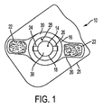
図1は本発明による創傷治療用の装置/パッチ10の一つの実施形態を示す。好ましくは、パッチ10は、ヒトの皮膚表面に適合し接着することができる可撓性、装着型のパッチ10である。パッチ10は、さらに、「アノード」として識別される少なくとも一つの第1電極14、「カソード」として識別される少なくとも一つの第2電極16、およびそれらの間のギャップを規定するために互いに離れた関係にあって基部部材20上に支持される少なくとも一つの電源18を含む。第1電極14がアノードとして識別することが可能であり、第2電極16がカソードとして識別することが可能である一方で、当業者はこれらの指定を逆にすることが可能であることを認識する。示されるような実施形態において、基部部材20は剥離ライナー21上に載る。
FIG. 1 shows one embodiment of a device /
電極14、16の同心配置を有する丸い装置/パッチ10の一つの好ましい実施形態において、内側電極14は、好ましくはカソードであり、周辺電極は、好ましくはアノードである。この配置は、大量の流体が治癒過程の間に生み出される、図1に示されるような創傷治癒パッチ装置において好ましい。流体は望ましくない匂いをもたらす傾向があり、パッチの機能を妨害することがある。こうした実施形態において、周辺アノード電極は、好ましくは、活性電極であり、電離療法用に設定される。好ましくは、こうした実施形態において、パッドなどの吸収性基材(図1には示されていない)が内側電極に取り付けられる。好ましくは、内側電極は逆イオン泳動などの方法により、吸収基材によって吸収されようとする創部からの過剰の流体を容易に除去するように設定される。
In one preferred embodiment of the round device /
パッチ10は、一部の好ましい実施形態により直流(ガルバニ電流)を生み出し、他の実施形態により交流または脈流を生み出す薄い電源18を備える。直流と交流または脈流間の選択は、損傷の性質および程度、および創傷状態における痛みの関与に応じて決められる。
The
装置10は創傷治療での使用に有効であるあらゆる適するサイズおよび形状にあることが可能である。図1は丸い装置の一つの非限定実施例を示す。装置の幅は約1cm未満〜約20cmに変動することができると共に、装置の長さは約2cm〜約30cmの範囲にあることができる。より小さいかまたはより大きな次元も可能である。装置10は、装置10がその上に貼られる場合に、少なくとも患者の輪郭に適合するように患者の皮膚に接触するような表面を可能とする薄くて可撓性のある材料から作製される。パッチ10は、パッチ10が創部または周囲の皮膚/組織に適用することを容易にする、図1に示される接着剤22を備えることが可能である。代わりの結合手段も可能である。基部部材20の一部を覆うように示されているが、一方で、当業者は、接着剤22が本発明の範囲から逸脱することなく示されるものよりも多いかまたは少ない表面を覆うことが可能であることを理解する。
The
好ましくは、電源18は、電源を電極に接続するために用いることが可能である第1端子24および第2端子26などの複数の端子を有する。示されるように、両方の端子24、26は、同じ周辺電極16に接続される。第3端子(電源による隠れのせいで示されていない)は、電源18を中心電極14に接続する。この配置は、好ましくは、よりよい電流分布を提供することが可能である。
Preferably, the power source 18 has a plurality of terminals such as a
前述のように、電源18は二つの電極14、16に接続することが可能である。任意の実施形態において、電源18はパッチ10の電極の一つに連結することが可能であるか、または代わりに電源18は電極14、16の近くに配置することが可能である。図1に示されるような実施形態において、電源18は第1電極14にできるだけ近づけて位置付けられると共に、その第1電極14の統合部分であることが可能である。
As described above, the power source 18 can be connected to the two
上述のように、パッチ10は、さらに、第1電極14、第2電極16、および電源18を支持する基部部材20を含むと共に、直接また間接に、それらの間のギャップ28を規定するため、第1電極14と第1電極16を互いに離れた関係に維持する。一つの実施形態において、ギャップ28は約5mmを超え〜約10mmにある範囲を含むことが可能である;ギャップサイズは、少なくとも一部において、装置10のサイズに応じて決まる。5〜10mmの最小範囲が、亜鉛などの酸化剤の生成が望ましい関連実施形態から誘導されることは、注目される。しかし、酸化剤生成用の構造が創傷治療用の構造とは異なることが可能であることは注目される;例えば、酸化剤の生成用には、ヒドロゲルは二つの電極間の境界面を占めることが可能である。好ましくは、表面創傷治療および電離療法的皮膚創傷治療が望ましい場合、二つの電極間のギャップ境界面28はヒドロゲルを含む。
As described above, the
好ましくは、導体(図1には示されない)は、電極14、16を電源18のそれぞれの端子24、26に連結する。電極14、16を電源18に連結することが可能である導体の例には、配線(平らなまたは丸い)、導電性インク、導電性接着剤、印刷接続手段、ハンダ付け接続手段、UVにより接着される接続手段、接着接続手段、導電性EVA溶接、および/またはそれらの組合せが挙げられるがそれらに限定されない。
Preferably, conductors (not shown in FIG. 1) connect the
図1の実施形態は円形の電極14、16および円形電源18を説明するが、一方で、他の形状の電極および電源は本発明の範囲から逸脱することなく用いることが可能である。図1は中心電極14および周辺電極16での電極14、16の同心配置を示す。図1は基部部材上の電極および電池の一つだけの可能な配置を説明するが、他の配置は本発明の範囲から逸脱することなく用いることが可能である。図1において、両方の電極14、16は、湿潤表面および加えてパッチと対象の身体部分間の導電性境界面手段を提供することを容易に促進するヒドロゲル30により被覆される。任意に、ヒドロゲル30は医薬活性剤を含有することが可能である。図のように、ヒドロゲルは、湿潤表面の例ならびに導電性境界面の例として考えることが可能である。導電性境界面が、また、導電性接着剤であることが可能であり、他方、本明細書において記載される創傷治癒装置/パッチに関連して用いられる湿潤表面が、好ましくは導電性接着剤でないことは、注目される。
While the embodiment of FIG. 1 illustrates
装置10がキットの一部である代替実施形態において、ヒドロゲル30を電極上に予備被覆することは可能でない。こうしたキットにおいて、ヒドロゲルは個別に供給することが可能であり、装置10の使用の前に、充填孔を介して直接電極上に塗布するか、または代わりに創部上に直接塗布することに限定されないがそれらなどのあらゆる適するやり方で塗布することができる。
In an alternative embodiment where the
基部部材20は、任意に、創傷治療パッチ構成要素を収容することができるあらゆる適する材料から製造することが可能である。適する材料には、織布、不織布、ポリマー、導電性材料、非導電性材料、紙、カード紙、プラスチック、合成材料、天然材料、布地、金属、木材、ガラス、パースペクス、またはそれらの組合せが挙げられるがそれらに限定されない。好ましくは、基部部材の材料は非導電性材料である。さらに好ましくは、基部部材はポリエステルから作製される。任意に、基部部材20は、あらゆる適する結合手段により同一平面上の領域に重ねるかまたは接続することができる複数の材料から作製することができる。好ましくは、基部部材20は一つの連続材料片から作製される。
本発明の好ましい実施形態により、電源18は電気化学セルであることが可能である。好ましい実施形態において、電源18は薄くて可撓性があることが可能である。一つの実施形態において、電源18は使い捨てであることが可能である。代わりの実施形態において、電源18は再充電することが可能である。 According to a preferred embodiment of the present invention, the power source 18 can be an electrochemical cell. In a preferred embodiment, the power source 18 can be thin and flexible. In one embodiment, the power source 18 can be disposable. In an alternative embodiment, the power source 18 can be recharged.
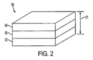
図2は、本発明の実施形態による代表的な電源50の略図を示す。好ましくは、電源50は薄くて可撓性がある。本明細書において用いられる用語「電源」には、化学エネルギーが自発的電子移動反応により電気エネルギーに転化されるあらゆる適するセルが挙げられるがそれらに限定されない。用語には、非自発的反応、ガルバニ電池、電解槽、および/またはそれらの組合せが含まれる。図2の実施形態において、電源は電気化学セルとして表される。電気化学セル50の厚さ51は、4mm以下、さらに好ましくは2mm以下、最も好ましくは1mm以下であることが可能である。現在好ましい実施形態において、電気化学セル50は、その間に置かれる正極層52、負極層54、および電解質層56を含む。一例として、適する電気化学セル50は、それらそれぞれが本明細書においてそれらの全体にわたって参考のために包含される米国特許第5,652,043号、第5,897,522号、および第5,811,204号に記載されている。簡単に、上記特定米国特許に記載されている電気化学セルは、小型設計の種々の小型で携帯可能電気駆動装置用の一次または再充電可能電源として用いることができる開放液体状態の電気化学セルである。一つの実施形態において、好ましい電気化学セル50は、不溶性負極54の第1層、不溶性正極52の第2層、および第1層54および第2層52間に置かれる水性電解質56の第3層を含むことが可能であると共に、(a)開放セルを常時湿潤状態に保持するための潮解性材料(示されていない)、(b)必要とされるイオン伝導率を得るための電気活性可溶性材料(示されていない)、および(c)第1および第2層を第3層に付着させるための必要な粘度を得るための水溶性ポリマー(示されていない)を含むことが可能である。 FIG. 2 shows a schematic diagram of an exemplary power supply 50 according to an embodiment of the present invention. Preferably, the power supply 50 is thin and flexible. As used herein, the term “power source” includes, but is not limited to, any suitable cell in which chemical energy is converted to electrical energy by a spontaneous electron transfer reaction. The term includes involuntary reactions, galvanic cells, electrolytic cells, and / or combinations thereof. In the embodiment of FIG. 2, the power source is represented as an electrochemical cell. The thickness 51 of the electrochemical cell 50 can be 4 mm or less, more preferably 2 mm or less, and most preferably 1 mm or less. In the presently preferred embodiment, electrochemical cell 50 includes a positive electrode layer 52, a negative electrode layer 54, and an electrolyte layer 56 disposed therebetween. By way of example, suitable electrochemical cells 50 are disclosed in US Pat. Nos. 5,652,043, 5,897,522, and 5, each of which are incorporated herein by reference in their entirety. 811,204. Briefly, the electrochemical cell described in the above specific US patent is an open liquid state electrochemical cell that can be used as a primary or rechargeable power source for various small and portable electric drives of small design. is there. In one embodiment, a preferred electrochemical cell 50 includes a first layer of insoluble negative electrode 54, a second layer of insoluble positive electrode 52, and a third layer of aqueous electrolyte 56 placed between first layer 54 and second layer 52. And (a) a deliquescent material (not shown) to keep the open cell wet at all times, (b) electroactive solubility to obtain the required ionic conductivity It may include a material (not shown), and (c) a water soluble polymer (not shown) to obtain the required viscosity for attaching the first and second layers to the third layer. .
なお、別の実施形態において、電気化学セルは、例えば、それが本明細書においてその全体にわたって参考のために包含される米国特許第6,421,561号に記載されているような、複数の内臓式直列接続ガルバニ電源を含むことが可能である。開示された電気化学セルのいくつかの好ましい実施形態は、(i)濾紙、プラスチック膜、セルロース膜および布に限定されないがそれらなどの多孔質物質中に電解質層を入れること、(ii)不溶性正極の第1層に二酸化マンガン粉末を含ませると共に、不溶性負極の第2層に亜鉛粉末を含ませること、(iii)不溶性負極の第1層および/または不溶性正極の第2層に、さらに、炭素粉末を含ませること、(iv)塩化亜鉛、臭化亜鉛、フッ化亜鉛および水酸化カリウムから電気活性溶解性物質を選択すること、(v)不溶性負極の第1層に酸化銀粉末を含ませると共に不溶性正極の第2層に亜鉛粉末を含ませ、電気活性溶解性材料が水酸化カリウムであること、(vi)不溶性負極の第1層にカドミウム粉末を含ませると共に不溶性正極の第2層に酸化ニッケル粉末を含ませ、電気活性溶解性材料として水酸化カリウムを選択すること、(vii)不溶性負極の第1層に鉄粉末を含ませると共に不溶性正極の第2層に酸化ニッケル粉末を含ませ、電気活性溶解性材料として水酸化カリウムを選択すること、(viii)不溶性負極の第1層および不溶性正極の第2層に酸化鉛粉末を含ませ、次に、セルが極に印加される電圧により荷電され、電気活性溶解性材料としてこの場合に硫酸を選択すること、(ix)潮解性材料および電気活性溶解性材料が同一の材料であってよく、たとえば、塩化亜鉛、臭化亜鉛、フッ化亜鉛および水酸化カリウムなどであること、(x)潮解性材料が臭化カルシウム、二リン酸カリウムおよび酢酸カリウムからなる群から選択されること、(xi)水溶性ポリマーがポリビニルアルコール、ポリアクリルアミド、ポリアクリル酸、ポリビニルピロリドン、ポリエチレンオキシド、寒天、アガロース、でんぷん、ヒドロキシエチルセルロースおよびそれらの組合せおよびコポリマーであることができること、(xii)水溶性ポリマーおよび潮解性材料が同一の材料であってよく、たとえば、デキストリン、硫酸デキストランおよびそれらの組合せおよびコポリマーなどであることを含む。電気化学セルは、好ましくは、上述のあらゆる1以上の実施形態を組み込むことが可能である。本発明による電気化学セル用の好ましい構造は、毒性化合物のないような組合せを含む。 In another embodiment, the electrochemical cell comprises a plurality of cells, for example as described in US Pat. No. 6,421,561, which is incorporated herein by reference in its entirety. A built-in series connected galvanic power supply can be included. Some preferred embodiments of the disclosed electrochemical cell include (i) placing the electrolyte layer in a porous material such as, but not limited to, filter paper, plastic membranes, cellulose membranes and fabrics, (ii) insoluble positive electrodes And (iii) the first layer of the insoluble negative electrode and / or the second layer of the insoluble positive electrode, and carbon dioxide powder. Including powder; (iv) selecting an electroactive soluble material from zinc chloride, zinc bromide, zinc fluoride and potassium hydroxide; (v) including silver oxide powder in the first layer of the insoluble negative electrode. In addition, zinc powder is included in the second layer of the insoluble positive electrode, and the electroactive soluble material is potassium hydroxide. (Vi) cadmium powder is included in the first layer of the insoluble negative electrode and insoluble. (2) Including the nickel oxide powder in the second layer of the electrode and selecting potassium hydroxide as the electroactive soluble material; (vii) including the iron powder in the first layer of the insoluble negative electrode and the second layer of the insoluble positive electrode Including nickel oxide powder and selecting potassium hydroxide as the electroactive soluble material; (viii) including a lead oxide powder in the first layer of the insoluble negative electrode and the second layer of the insoluble positive electrode; Selecting sulfuric acid as the electroactive soluble material in this case, which is charged by the voltage applied to the poles, (ix) the deliquescent material and the electroactive soluble material may be the same material, for example zinc chloride Zinc bromide, zinc fluoride and potassium hydroxide, etc. (x) the deliquescent material is selected from the group consisting of calcium bromide, potassium diphosphate and potassium acetate; i) the water-soluble polymer can be polyvinyl alcohol, polyacrylamide, polyacrylic acid, polyvinyl pyrrolidone, polyethylene oxide, agar, agarose, starch, hydroxyethyl cellulose and combinations and copolymers thereof; (xii) water-soluble polymers and deliquescence The sexual material may be the same material, including, for example, dextrin, dextran sulfate and combinations and copolymers thereof. The electrochemical cell can preferably incorporate any one or more of the embodiments described above. Preferred structures for electrochemical cells according to the present invention include such combinations that are free of toxic compounds.
好ましくは、電源は適する印刷技術を用いて塗布される。 Preferably, the power source is applied using a suitable printing technique.
図1の電源18などの好ましい電源は、約0.5V〜約20V間の範囲にある直流電気電位(電圧)を提供する。こうした電気電位は、単一電気化学セルまたは多くの電気化学セルにより供給され、一緒に連結されて、望ましい電圧を与えることができる。好ましくは、電源により供給される電流およびまたは電圧は固定され、使用者によって調整することはできない;使用者には、患者または創傷治療の対象または治療を施行する個人が挙げられるがそれらに限定されない。なお別の実施形態において、電気電位は調整されて以下の範疇の少なくとも一つを満足させることが可能である: A preferred power supply, such as the power supply 18 of FIG. Such an electrical potential can be supplied by a single electrochemical cell or many electrochemical cells and coupled together to provide the desired voltage. Preferably, the current and / or voltage supplied by the power source is fixed and cannot be adjusted by the user; the user may include, but is not limited to, the patient or subject of wound treatment or the individual performing the treatment . In yet another embodiment, the electrical potential can be adjusted to satisfy at least one of the following categories:
電圧は、活性物質の創部または創部周辺の領域中へのイオン泳動送達を可能とするように調整することが可能である。その目的のために、電圧は約0.002mA/cm2〜10mA/cm2間の電流を提供するように調整することが可能である。
The voltage can be adjusted to allow for iontophoretic delivery of the active agent into the wound or the area around the wound. For that purpose, the voltage can be adjusted to provide a current between about 0.002 mA /
電圧は、皮膚中におよび皮膚を通して通過する過剰の電流をもたらすことから生じることがある刺激を最小化するように調整することが可能である。従って、好ましい実施形態において、電圧は調整することが可能であって、約0.5V〜約20V間の範囲内に調整することが可能であり;およびさらに好ましい実施形態において、電圧は調整可能であって、約1V〜約4.5V間の範囲内に調整することが可能である。好ましい実施形態において、あらゆる調整は、センサーなどの自動機構を通してなされることが可能である。交流または脈流の場合に、出力は、創傷状態の性質および程度に応じて、最適の電圧、電流および電流プロフィール(周波数、振幅および波形)に合わせて調整することが可能である。 The voltage can be adjusted to minimize irritation that may result from causing excessive current to pass through and through the skin. Thus, in a preferred embodiment, the voltage can be adjusted and can be adjusted within a range between about 0.5V to about 20V; and in a more preferred embodiment, the voltage is adjustable. Thus, it is possible to adjust within a range between about 1V and about 4.5V. In a preferred embodiment, any adjustment can be made through an automated mechanism such as a sensor. In the case of alternating current or pulsatile flow, the output can be adjusted for optimal voltage, current and current profile (frequency, amplitude and waveform) depending on the nature and extent of the wound condition.
最終電流は、任意にDC−DC電子変換器を用いて調整することが可能である。交流または脈流の場合に、出力はDC−AC電子変換器を用いて生成することが可能である。 The final current can optionally be adjusted using a DC-DC electronic converter. In the case of alternating current or pulsating flow, the output can be generated using a DC-AC electronic converter.
任意に、電源は単一電気化学セルであることが可能である。しかし、電源は一つのセルに限定される必要はなく、複数の接続された電気化学セル、複数のバッテリー、および/または供給電流相を増大させ、制御し、変えるように設定されるエレクトロニクスを含むことが可能であり、電源装置は薄くて可撓性がある。装置中の電気化学セルは、好ましくは、対象の望ましい身体部分に電気電位(電圧)を提供する。 Optionally, the power source can be a single electrochemical cell. However, the power source need not be limited to a single cell, but may include multiple connected electrochemical cells, multiple batteries, and / or electronics configured to increase, control and change the supply current phase. It is possible that the power supply is thin and flexible. The electrochemical cell in the device preferably provides an electrical potential (voltage) to the desired body part of the subject.
電源装置は、任意に、装置上のあらゆる適する位置に置くことが可能である。 The power supply can optionally be placed in any suitable location on the device.
装置への電源装置は、約1%〜約99%間の負荷サイクルおよびパルス繰り返し率を提供することが可能である。電源装置の周波数は、好ましくは、約1Hz〜約1000Hzであることが可能である。電源装置は、装置に、約0.2V〜約100V範囲の電圧を提供することが可能である。 The power supply to the device can provide a duty cycle and pulse repetition rate between about 1% and about 99%. The frequency of the power supply can preferably be from about 1 Hz to about 1000 Hz. The power supply can provide a voltage in the range of about 0.2V to about 100V to the device.
さて、図1に戻って、電極14、16は、導電性材料から作製することが可能である。好ましくは、電極14、16は、金属、例えば金属フォイルまたは適する裏打ち上に蒸着するかまたは塗布される金属から形成される。電極14、16は、例えば、シルクプリント、オフセット印刷、ジェット印刷、積層、物質蒸発または粉末分散などの適する印刷技術により、装置に塗布することが可能であるがそれらに限定されない。
Now, returning to FIG. 1, the
好ましくは、電極14、16は、創傷治療に有効である金属から作製される。一つの好ましい実施形態において、電極14、16の少なくとも一つは銀金属を含む。生成銀イオンは創傷治療において治療的に用いることができる。さらに好ましい実施形態において、少なくとも一つの電極14、16は銀および塩化銀の両方を含む。なお、別の好ましい実施形態において、電極14、16の少なくとも一つは炭素またはグラファイトを含む。
Preferably, the
なお別の好ましい実施形態において、電極14、16の少なくとも一つは亜鉛を含む。亜鉛電極からその場で生成される亜鉛イオンは、装置10によりイオン泳動的に創部に容易に送達することができる。
In yet another preferred embodiment, at least one of the
ヒドロゲルまたは代わりの導電性流体が二つの電極間の境界面28(図1において示されていない)を占める実施形態において、亜鉛イオンは創傷の表面治療、または表面とイオン泳動皮膚創傷治療の組合せ用に用いることができる。亜鉛イオンの表面処理とイオン泳動送達の比率は、とりわけ極間のギャップ28のサイズにより制御することができる。好ましくは、ギャップ28が小さくなるほど、表面処理の方がイオン泳動送達に較べてより多くなる。
In embodiments where the hydrogel or alternative conductive fluid occupies the interface 28 (not shown in FIG. 1) between the two electrodes, the zinc ions are for wound surface treatment or a combination of surface and iontophoretic skin wound treatment. Can be used. The ratio of zinc ion surface treatment to iontophoretic delivery can be controlled, inter alia, by the size of the
亜鉛イオンは、やけどを含む多くのタイプの創傷の回復を加速することができる。亜鉛の経口投与は創傷治療において有効でなく、亜鉛の酸化に対する感受性のせいで、例えば軟膏での亜鉛の局所適用は極めて限定された効果を有する。従って、装置10の亜鉛電極から生成する亜鉛イオンは、亜鉛による創傷治療の改善された方法を提供する。亜鉛イオンの特性は、創傷治療におけるそれらの効果的な使用を容易にする。亜鉛は、表面創傷治療および深い創傷治療において有効である直接の抗微生物効果(抗細菌、抗真菌および抗ウイルス)を有する。加えて、亜鉛は、抗原特異免疫を増強させることにより、間接の抗微生物効果を有する。さらに、亜鉛は抗炎症作用を有し、肥満細胞および好塩基球に作用し、ヒスタミン放出および組織損傷を減少させる。亜鉛は、また、上皮成長を加速する。亜鉛の生物学的効果はその皮膚湿潤効果と組み合わせることができる。なおさらに、亜鉛イオンは、限定されないが、水溶性薬物、非荷電薬物および例えばC.D.(シクロデキストリン)を用いる疎水性薬物などの他の薬物を、電気浸透機構により創傷中に送達するための駆動力として用いることができる。駆動力は電流に比例する。亜鉛電極は、比較的高い電流を容易に促進することができ、従って、比較的低い電圧により、亜鉛は他の薬物の送達のための重要な駆動力として作用することができる。
Zinc ions can accelerate the recovery of many types of wounds, including burns. Oral administration of zinc is not effective in wound treatment, and because of its sensitivity to zinc oxidation, topical application of zinc, for example in an ointment, has a very limited effect. Thus, the zinc ions generated from the zinc electrode of
電極用の適する金属の他の例には、銅、二酸化マンガン、アルミニウム、白金、ステンレス鋼、金、チタン、またはそれらの組合せが挙げられる。あるいは、電極は、金属粉末/フレーク、粉末化グラファイト、炭素繊維、または他の公知の導電性充填剤材料などの導電性充填剤を含有する疎水性ポリマーマトリクスから形成することが可能である。金属および非金属材料を含むあらゆる他の導電性元素または化合物は、電極14、16の材料中に組み込むことができる。実施形態において、電極14、16は電源18に連結される薄いシートとして提供することが可能であるか、または、それらの間のギャップ28を規定するために互いに離れた関係にあって基部部材20上に印刷することが可能である。好ましくは、少なくとも一つの電極は活性電極であり、少なくとも一つの電極は対極である。任意に、活性電極は、カソードまたはアノードまたはカソードおよびアノードの両方であることができる。どの電極が活性電極であるかを規定することは、好ましくは、用いようとする組成物(例えば、配合物または医薬創傷治療剤)の電荷に応じて決まる。
Other examples of suitable metals for the electrodes include copper, manganese dioxide, aluminum, platinum, stainless steel, gold, titanium, or combinations thereof. Alternatively, the electrodes can be formed from a hydrophobic polymer matrix containing a conductive filler such as metal powder / flakes, powdered graphite, carbon fibers, or other known conductive filler materials. Any other conductive element or compound, including metallic and non-metallic materials, can be incorporated into the material of the
任意に、電極14、16領域は連続であるか、またはあらゆる形状または構造に形成することができる。任意に、各電極14、16は、同じ形状および/または同じ面積を持たないことが可能である。
Optionally, the
任意に、電極14、16は、同一平面および同一面の配置に限定されないがそれを含む互いの関係であらゆる適する配置にあることが可能である。好ましくは、電極14、16は、拡散域治療を容易に促進する配置にある。好ましくは、電極14、16は、創面の表面治療および/または皮膚治療を提供するように設定される。好ましい電極構造には、同心構造、両側性構造およびラビリンス構造が挙げられるがそれらに限定されない。
Optionally, the
任意に、パッチ10は、等しいかまたは等しくない数のアノードおよびカソードからなる複数の電極14、16を含むことができる。こうした多電極パッチは、同時に一つの組成物での異なる領域における複数の治療、または異なる身体部分または同じ身体部分における複数の組成物を提供することを容易にする。
Optionally, the
好ましくは、本発明の装置は創面および周辺領域に対する電気刺激を提供する。電気刺激は創傷治療において重要である。電気刺激は傷ついた組織の中および周辺の鬱血を減少させ、血液循環を増大させ、筋肉運動および感覚刺激および抹消神経刺激を生み出すのに有用である。 Preferably, the device of the present invention provides electrical stimulation to the wound surface and surrounding area. Electrical stimulation is important in wound treatment. Electrical stimulation is useful for reducing congestion in and around damaged tissue, increasing blood circulation, and creating muscle movement and sensory and peripheral nerve stimulation.
筋肉の感覚刺激は痛み制御を可能とする。マイクロアンプ刺激は、本発明の装置の適用に続いて数分後に一般的に起こり得る電気感覚脱失をもたらすことができる。筋肉運動刺激は、鍼治療のつぼを刺激するため、筋肉テタニーを創り出して痛み−発作サイクルを壊すことに役立つため、筋肉再教育、廃用性萎縮防止のため、および創傷治癒のために実施することができる。単相性パルスは、開放創、局部細菌感染および癒着不能骨折などの状態における細胞再生の原因であると考えられる、刺激された組織における電気荷電の一時的な集積を可能とする。 Muscle sensory stimulation allows pain control. Microamp stimulation can result in electrosensory loss that can typically occur after a few minutes following application of the device of the present invention. Muscle exercise stimulation is performed to stimulate acupuncture vases, create muscle tetany and help break the pain-stroke cycle, retrain muscles, prevent disuse atrophy, and wound healing be able to. Monophasic pulses allow the temporary accumulation of electrical charge in stimulated tissue that is thought to be responsible for cell regeneration in conditions such as open wounds, local bacterial infections and non-adhesive fractures.
従って、本発明の装置から得られる電気刺激は、内因性電流フローを増大させ、傷ついた領域におけるセルがそれらの静電容量を回復することを可能とする。抵抗は減少し、生体電気が流れ込みホメオスタシスを再建することを可能とする。このプロセスは、治癒中に起こる多くの生化学反応を開始し持続させることに役立つ。外傷に対する反応として起こる筋肉けいれんは、血液供給の減少を引き起こし、局部低酸素症、有害な代謝産物の集積、および痛みをもたらす。これは、次に、ATP合成の減少をもたらす。こうして、MET(筋肉エネルギー技術)刺激はATPの補充をもたらす。加えて、創傷の電気刺激は、コラーゲン形成を増大させる成長因子受容体の濃度を増大させる。これは、潰瘍形成を引き起こすことにおける主要機構が静脈高血圧による成長因子の除去であるという仮説の観点から重要である。 Thus, the electrical stimulation obtained from the device of the present invention increases the intrinsic current flow and allows cells in the damaged area to recover their capacitance. The resistance is reduced, allowing bioelectricity to flow and rebuilding homeostasis. This process helps to initiate and sustain many biochemical reactions that occur during healing. Muscle spasms that occur as a response to trauma cause a reduction in blood supply, resulting in local hypoxia, accumulation of harmful metabolites, and pain. This in turn leads to a decrease in ATP synthesis. Thus, MET (muscle energy technology) stimulation results in ATP supplementation. In addition, electrical stimulation of the wound increases the concentration of growth factor receptors that increase collagen formation. This is important in view of the hypothesis that the primary mechanism in causing ulceration is the removal of growth factors by venous hypertension.
本発明の装置10から得られる電気刺激の電流極性は、任意に、創傷の特定タイプおよび創傷の位置により選択することができる。負電流(カソード)は一部のタイプの骨および神経修復を達成するために一層有益であることが可能である。正の(アノード)電流は一部のタイプの皮膚損傷治療において一層有効であることが可能である。
The current polarity of the electrical stimulation obtained from the
好ましくは、装置10は接合層30を含む。好ましくは、パッチ10と皮膚間の接合層30は湿潤導体層である。好ましくは、湿潤導体層は二つの主要機能を有する:(1)本出願の背景に詳述するような治療利点を有する湿潤表面を提供すること、および(2)また本発明の背景部において説明されるようにまた治癒利点を及ぼす電流を伝導すること。湿潤表面および電流の利点を組み合わせることにより、相乗効果がたぶん得られる。
Preferably, the
任意の接合材料30の一般性を傷つけることのない一つの例は、導電性ヒドロゲルである。ヒドロゲルは水中で膨張するポリマーである。ポリマーゲルは、架橋により接続される長いポリマー鎖からなる本質的に無限の分子である。
One example that does not harm the generality of the
一般的に、ヒドロゲルは、水、ゲル化剤、親水性溶媒(「湿潤剤」とも呼ばれる)および電解質からなる。ヒドロゲルは、好ましい創部のケア能力を得るように制御することができる水含量、ゲル化剤、電解質含量およびpHなどの各種特性を有することが可能である。リッポン(Rippon)らへの米国特許出願第20040028739号に開示されているヒドロゲルを含むあらゆる適するヒドロゲルを用いることが可能である。 In general, a hydrogel consists of water, a gelling agent, a hydrophilic solvent (also called a “wetting agent”) and an electrolyte. The hydrogel can have various properties such as water content, gelling agent, electrolyte content and pH that can be controlled to obtain a preferred wound care capability. Any suitable hydrogel can be used, including the hydrogel disclosed in US Patent Application No. 20040028739 to Rippon et al.
任意に、湿潤導体層30は活性薬物を含み、それ自体薬物リザーバとして機能することができる。
Optionally, the
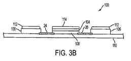
図3は、本発明による創傷治療のための装置/パッチ100の代替実施形態を示す。図3への参照は特記のない限り図3Aおよび図3B両方への参照を含むことは留意される。好ましくは、パッチ100は、ヒトの皮膚表面に適合し付着することができる可撓性装着型パッチ100である。パッチ100は、さらに、「アノード」として識別される少なくとも一つの第1電極104、「カソード」として識別される少なくとも一つの第2電極106、およびそれらの間のギャップを規定するために互いに離れた関係にあって基部部材110上に支持される少なくとも一つの電源108を含む。第1電極104はアノードとして識別することが可能であり、第2電極106はカソードとして識別することが可能である一方で、当業者はこれらの指定は逆にすることが可能であることを理解する。示される実施形態において、基部部材110は剥離ライナー111上に載る。パッチ100は、創部または周辺皮膚/組織へのパッチ100の接着を容易にする接着剤(示されていない)(図1の22に類似の)を備えることが可能である。別の結合手段は可能である。
FIG. 3 shows an alternative embodiment of a device /
パッチ100は、一部の好ましい実施形態により直流(ガルバニ電流)を生み出し、他の実施形態により交流または脈流を生み出す薄い電源108を備える。直流および交流または脈流間の選択は、損傷の性質および程度、および創傷状態における痛みの関与に応じてなされる。
The
装置100は、創傷治療における使用に有効であるあらゆる適するサイズおよび形状からなることが可能である。図3は周辺電極106および中心電極104を有する丸い装置の一つの非限定実施例を示す。装置の幅は約1cm未満〜約20cmに変わることができると共に、装置の長さは約2cm〜約30cmの範囲にあることができる。より小さなまたはより大きな次元も可能である。装置100は、装置100がその上に貼られる場合に、少なくとも患者の皮膚に接触して患者の輪郭に適合するような表面を可能とする薄くて可撓性のある材料から作製される。
The
装置100の構成要素は、実質的に、図1の装置10に対して上に記載された通りである。装置100は、好ましくは周辺電極106上に被覆されるヒドロゲル112湿潤表面を含む。装置100は、さらに、中心電極104上に置かれる基板114を含む。代替実施形態において、ヒドロゲルなどの湿潤表面は、任意に、中心電極104上に被覆することができ、基板は周辺電極106上に置くことができる。図3に示されるような実施形態において、少なくとも一つの湿潤表面は、吸収性基板およびゲル、クリームまたはローションであることが可能である導電性担体を含む。好ましくは、基板114は導電性担体を吸収することができる。
The components of the
好ましい代替実施形態において、基板114は配合物を保持するための多孔質および/または吸収材料を含む。好ましくは、基板114は、電極104、106に電流を印加する際に、電極104、106の少なくとも一つと対象の皮膚の間に置かれる;パッチ100は電流を対象の皮膚に送達することができる。活性物質を含む配合物を保持するこうした基板114の一つの例は、ずぶ濡れのパッドであるであろう。
In a preferred alternative embodiment, the
例として、図3Bは本発明の実施形態による創傷治療装置100の概略断面図の一つの例を提供する。創傷治療装置100の概略断面図は、一般に、本明細書において示される各実施形態の断面図の代表例である。図3Bに示されるような装置100の構成要素の説明は、図1〜3Aにおいて上に記載された通りである。
By way of example, FIG. 3B provides one example of a schematic cross-sectional view of a
好ましくは、ゲルは、水、ゲル化剤、および医薬配合物分野の当業者には公知の他の賦形剤を含むことが可能である。ゲル化剤は、(1)ポリアクリレートおよびポリアクリレート・コポリマー樹脂、例えば、商品名カーボポル(Carbopol)(Fiedlerの254〜256を参照すること)、とりわけ製品カーボポル934、940および941で、およびオイドラギット(Eudragit)(Fiedlerの486〜487を参照すること)、とりわけ製品オイドラギットE、L、S、RLおよびRSとして知られ市販されているものなど、および最も特定的には製品オイドラギットE、LおよびSのポリアクリル酸およびポリアクリル酸/メタクリル酸樹脂、(2)アルキルセルロース、例えば、メチル−、エチル−およびプロピル−セルロース;ヒドロキシアルキル−セルロース、例えば、ヒドロキシプロピル−セルロースおよびヒドロキシプロピル−メチル−セルロースなどのヒドロキシプロピルアルキル−セルロース;アシル化セルロース、例えば、酢酸セルロース、酢酸フタル酸セルロース、酢酸コハク酸セルロースおよびフタル酸ヒドロキシルプロピルメチルセルロース;およびカルボキシメチル・セルロース・ナトリウムなどのそれらの塩などのポリマーを含むことが可能である。本発明による使用に適するこうした製品の例には、例えば、商品名キウセル(Kiucel)およびメトセル(Methocel)(Fiedlerの688 and 790を参照すること)、とりわけ製品クルセル(Klucel)LF、MF、GFおよびEF、およびケトセル(Kethocel)K100、K15、K100M、E5M、E15、E15MおよびE100Mで知られ市販されているもの;(3)例えばポリ−N−イニルピロリドンを含むポリビニルピロリドン、およびビニルピロリドン−酢酸ビニル・コポリマーなどのシニルピロリドン・コポリマーが挙げられる。本発明による使用に適するこうした化合物の例には、例えば、商品名コリドン(Kollidon)(または、米国ではポビドン(Povidone))(Fiedlerの694〜696を参照すること)、とりわけ製品コリドン30および90で知られ市販されているもの;(4)例えばポリ酢酸ビニルおよびアルコールを含むポリビニル樹脂、ならびにトラガントゴム、アラビアゴム、アルギン酸塩、例えばアルギン酸およびその塩、例えばアルギン酸ナトリウムを含む他の高分子材料、および(5)アタパルジャイト、ベントナイト、および親水性二酸化ケイ素、例えば、アルキル化(例えば、メチル化)シリカゲル、とりわけ商品名アエロジル(Aerosil)(Handbook of Pharmaceutical Excipients,253〜256(Raymond C.Rowe ed.,Pharmaceutical Press)を参照すること)、とりわけ製品アエロジル130、200、300、380、0、OX50、TT600、MOX80、MOX170、LK84およびメチル化アエロジルR972で知られ市販されているコロイド状二酸化ケイ素製品を含むケイ酸塩などの無機増粘剤が挙げられる。
Preferably, the gel can include water, gelling agents, and other excipients known to those skilled in the pharmaceutical formulation arts. Gelling agents include (1) polyacrylate and polyacrylate copolymer resins, such as the product name Carbopol (see Fiedler 254-256), especially the products Carbopol 934, 940 and 941, and Eudragit ( Eudragit (see Fiedler 486-487), especially those known as the product Eudragit E, L, S, RL and RS, such as those commercially available, and most particularly of the product Eudragit E, L and S Polyacrylic acid and polyacrylic acid / methacrylic resins, (2) alkylcelluloses such as methyl-, ethyl- and propyl-cellulose; hydroxyalkyl-celluloses such as hydroxypropyl-cellulose and hydride Hydroxypropylalkyl-celluloses such as xylpropyl-methyl-cellulose; acylated celluloses such as cellulose acetate, cellulose acetate phthalate, cellulose acetate succinate and hydroxylpropylmethylcellulose phthalate; and salts thereof such as carboxymethyl cellulose sodium It is possible to include polymers such as Examples of such products suitable for use according to the invention include, for example, the trade names Kiucel and Methocel (see Fiedler's 688 and 790), especially the products Klucel LF, MF, GF and EF, and those known and commercially available in Ketocel K100, K15, K100M, E5M, E15, E15M and E100M; (3) polyvinylpyrrolidone including, for example, poly-N-ynylpyrrolidone, and vinylpyrrolidone-acetic acid Examples include sinylpyrrolidone copolymers such as vinyl copolymers. Examples of such compounds suitable for use in accordance with the present invention include, for example, the trade names Kollidon (or Povidone in the United States) (see Fiedler 694-696), especially products Kollidon 30 and 90. Known and commercially available; (4) polyvinyl resins including, for example, polyvinyl acetate and alcohol, and other polymeric materials including tragacanth gum, gum arabic, alginates such as alginic acid and salts thereof such as sodium alginate, and ( 5) Attapulgite, bentonite, and hydrophilic silicon dioxide, such as alkylated (eg methylated) silica gel, especially the trade name Aerosil (Handbook of Pharmaceutical Exc) pients, 253-256 (see Raymond C. Rowed ed., Pharmaceutical Press), especially
好ましくは、ヒドロゲルおよび/またはゲルは高い導電率を有する。比較として、導電性境界面として用いられるヒドロゲルは、好ましくは、約150オーム未満の電気抵抗を有する。 Preferably, the hydrogel and / or gel has a high conductivity. For comparison, the hydrogel used as the conductive interface preferably has an electrical resistance of less than about 150 ohms.
特に好ましい実施形態において、本発明のヒドロゲルまたはゲル(「組成物」とも呼ばれる)は、1以上の活性成分(「活性剤」および「薬物」とも呼ばれる)またはそれらの医薬的に許容可能な塩の安全で有効な量を含む。(1)湿潤表面、(2)電流、および(3)1以上の活性成分の有効量の利点を組み合わせることにより、相乗効果を得ることが可能である。 In particularly preferred embodiments, the hydrogels or gels (also referred to as “compositions”) of the present invention comprise one or more active ingredients (also referred to as “active agents” and “drugs”) or pharmaceutically acceptable salts thereof. Includes safe and effective amounts. By combining the advantages of (1) a wet surface, (2) current, and (3) an effective amount of one or more active ingredients, a synergistic effect can be obtained.
本明細書において用いられる用語「安全で有効な量」は、治療しようとする創傷状態を修正するか、または望ましい皮膚利点を送達するために十分高いが、しかし、健全な医学上の判断の範囲内の合理的な利点対リスク比で深刻な副作用を避けるために十分低い活性成分の量を意味する。活性成分の安全で有効な量であるものは、特定活性剤、皮膚を浸透する活性剤の能力、使用者の年齢、健康状態、および皮膚状態、および他の類似の因子により変動する。 The term “safe and effective amount” as used herein is high enough to correct the wound condition to be treated or to deliver the desired skin benefits, but to the extent of sound medical judgment Within a reasonable benefit-to-risk ratio means an amount of active ingredient low enough to avoid serious side effects. What is a safe and effective amount of the active ingredient will vary depending on the specific active agent, the ability of the active agent to penetrate the skin, the age, health and skin condition of the user, and other similar factors.
本明細書において用いられる用語「医薬的に許容可能な塩」は、過度の毒性、刺激、不和合性、不安定性、炎症、およびアレルギー反応などなしで、ヒトの組織と接触しての使用に適するあらゆる一般的に用いられる塩を指すことが可能である。 As used herein, the term “pharmaceutically acceptable salt” is intended for use in contact with human tissue without undue toxicity, irritation, incompatibility, instability, inflammation, and allergic reactions. It is possible to refer to any suitable commonly used salt.
一般的に、本発明の活性剤は、組成物の重量で約0.001%を超え約50%未満、好ましくは約0.01%〜約10%を構成する。より低い%およびより高い%は本発明により可能である。本発明の装置中に成長因子を用いる場合に、より低い%は一層好ましい。 Generally, the active agents of the present invention comprise greater than about 0.001% and less than about 50%, preferably from about 0.01% to about 10% by weight of the composition. Lower and higher percentages are possible with the present invention. Lower percentages are more preferred when using growth factors in the devices of the present invention.
本発明の装置と共に用いることが可能である任意の活性成分には、以下に詳述されるような非ステロイド抗炎症剤、局所麻酔剤、抗微生物および抗真菌剤、酸化剤、亜鉛、銀、組織成長用活性剤、成長因子、抗ウイルス剤、薬草および自然療法およびそれらのあらゆる組合せが挙げられるがそれらに限定されない: Optional active ingredients that can be used with the device of the present invention include non-steroidal anti-inflammatory agents, local anesthetics, antimicrobial and antifungal agents, oxidants, zinc, silver, as detailed below. Examples include, but are not limited to, tissue growth active agents, growth factors, antiviral agents, herbs and natural remedies and any combination thereof:
非ステロイド抗炎症活性剤(NSAIDS)
NSAIDSの例には、以下の範疇が挙げられるがそれらに限定されない:プロピオン酸誘導体、酢酸誘導体、フェナム酸誘導体、ビフェニルカルボン酸誘導体、およびオキシカム。これらNSAIDSのすべては、1991年1月15日にサンシャイン(Sunshine)らに発行され、本明細書において参考のため包含される米国特許第4,985,459号に十分に記載されている。有用なNSAIDSの例には、アセチルサリチル酸、イブプロフェン、ナプロキセン、ベノキサプロフェン、フルルビプロフェン、フェノプロフェン、フェンブフェン、ケトプロフェン、インドプロフェン、ピルプロフェン、カルプロフェン、オキサプロジン、プラノプロフェン、ムニロプロフェン、チオキサプロフェン、スプロフェン、アルミノプロフェン、チアプロフェン酸、フルプロフェン、およびブクロクス酸が挙げられる。また有用なものには、ヒドロコルチゲンなどを含むステロイド抗炎症剤がある。
Non-steroidal anti-inflammatory active agent (NSAIDS)
Examples of NSAIDS include, but are not limited to, the following categories: propionic acid derivatives, acetic acid derivatives, phenamic acid derivatives, biphenylcarboxylic acid derivatives, and oxicams. All of these NSAIDS are fully described in US Pat. No. 4,985,459, issued to Sunshine et al. On Jan. 15, 1991 and incorporated herein by reference. Examples of useful NSAIDS include acetylsalicylic acid, ibuprofen, naproxen, benoxaprofen, flurbiprofen, fenoprofen, fenbufen, ketoprofen, indoprofen, pyrprofen, carprofen, oxaprozin, pranoprofen, muniprofen , Thixaprofen, suprofen, aluminoprofen, thiaprofenic acid, fluprofen, and bucloxic acid. Also useful are steroidal anti-inflammatory agents including hydrocortigen and the like.
局所麻酔剤
局所麻酔剤の例には、ベンゾカイン、リドカイン、ブピバカイン、クロルプロカイン、ジブカイン、エチドカイン、メピバカイン、テトラカイン、ジクロニン、ヘキシルカイン、プロカイン、コカイン、ケタミン、プラモキシン、フェノール、およびそれらの医薬的に許容可能な塩が挙げられるがそれらに限定されない。
Examples of local anesthetics include benzocaine, lidocaine, bupivacaine, chlorprocaine, dibucaine, etidocaine, mepivacaine, tetracaine, diclonin, hexylcaine, procaine, cocaine, ketamine, pramoxine, phenol, and their pharmaceutically Examples include but are not limited to acceptable salts.
抗微生物および抗真菌活性剤
抗微生物および抗真菌活性剤の例には、ベータ・ラクタム薬物、キノロン薬物、シプロフロキサシン、ノルフロキサシン、テトラサイクリン、エリスロマイシン、アミカシン、2,4,4’−トリクロロ−2’−ヒドロキシ・ジフェニル・エーテル、3,4,4’−トリクロロバニリド、フェノキシエタノール、フェノキシプロパノール、フェノキシイソプロパノール、ドキシサイクリン、カプレオマイシン、クロルヘキシジン、クロルテトラサイクリン、オキシテトラサイクリン、クリンダマイシン、エタンブトール、イセチオン酸ヘキサミジン、メトロニダゾール、ペンタミジン、ゲンタマイシン、カナマイシン、リネオマイシン、メタサイクリン、メタナミン、ミノサイクリン、ネオマイシン、ネチルマイシン、パロモマイシン、ストレプトマイシン、トブラマイシン、ミコナゾール、塩酸テトラサイクリン、エリスロマイシン、亜鉛エリスロマイシン、エリスロマイシン・エストレート、ステアリン酸エリスロマイシン、硫酸アミカシン、塩酸ドキシサイクリン、硫酸カプレオマイシン、グルコン酸クロルヘキシジン、塩酸クロルヘキシジン、塩酸クロルテトラサイクリン、塩酸オキシテトラサイクリン、塩酸クリンダマイシン、塩酸エタンブトール、塩酸メトロニダゾール、塩酸ペンタミジン、硫酸ゲンタマイシン、硫酸カナマイシン、塩酸リネオマイシン、塩酸メタサイクリン、馬尿酸メテナミン、マンデル酸メテナミン、塩酸ミノサイクリン、硫酸ネオマイシン、硫酸ネチルマイシン、硫酸パロモマイシン、硫酸ストレプトマイシン、硫酸トブラマイシン、塩酸ミコナゾール、塩酸アマンファジン、硫酸アマンファジン、オクトピロックス、パラクロロメタ・キシレノール、ナイスタチン、トルナフテート、およびクロトリマゾールが挙げられるがそれらに限定されない。
Antimicrobial and antifungal active agents Examples of antimicrobial and antifungal active agents include beta-lactam drugs, quinolone drugs, ciprofloxacin, norfloxacin, tetracycline, erythromycin, amikacin, 2,4,4'-trichloro-2 '-Hydroxy diphenyl ether, 3,4,4'-trichlorovanylide, phenoxyethanol, phenoxypropanol, phenoxyisopropanol, doxycycline, capreomycin, chlorhexidine, chlortetracycline, oxytetracycline, clindamycin, ethambutol, isethionate hexamidine, Metronidazole, Pentamidine, Gentamicin, Kanamycin, Lineomycin, Metacycline, Methanamine, Minocycline, Neomycin, Netilmycin , Paromomycin, streptomycin, tobramycin, miconazole, tetracycline hydrochloride, erythromycin, zinc erythromycin, erythromycin estrate, erythromycin stearate, amikacin sulfate, doxycycline sulfate, capreomycin sulfate, chlorhexidine gluconate, chlorhexidine hydrochloride, chlortetracycline hydrochloride, oxytetracycline hydrochloride, , Clindamycin hydrochloride, ethambutol hydrochloride, metronidazole hydrochloride, pentamidine hydrochloride, gentamicin sulfate, kanamycin sulfate, lineneomycin hydrochloride, metacycline hydrochloride, methenamine hippurate, methenamine mandelate, minocycline hydrochloride, neomycin sulfate, netilmycin sulfate, paromomycin sulfate, sulfuric acid Streptomycin, sulfate Ramaishin, miconazole hydrochloride, hydrochloric amanfadine, amanfadine sulfate, octopirox, Parakurorometa-xylenol, nystatin, tolnaftate, and clotrimazole but tetrazole include, but are not limited to.
酸化剤
酸化剤は創傷治療において有用である。こうした酸化剤の例には、酸素、過酸化水素および過酸化ベンゾイルなどの過酸化物、ヨードおよびヨード−ポビドンなどのハロゲン元素種、ならびに次亜塩素酸塩イオンおよび過塩素酸塩種などの酸化ハロゲン種および亜鉛イオンが挙げられるがそれらに限定されない。キノンなどの有機酸化剤は、また、本発明による「酸化剤」の定義の中に含まれる。
Oxidizing agents Oxidizing agents are useful in wound treatment. Examples of these oxidants include peroxides such as oxygen, hydrogen peroxide and benzoyl peroxide, halogen element species such as iodo and iodo-povidone, and oxidation such as hypochlorite ions and perchlorate species. Non-limiting examples include halogen species and zinc ions. Organic oxidants such as quinones are also included within the definition of “oxidizer” according to the present invention.
なお、好ましい実施形態において、酸化剤は、電気回路の閉鎖の際に、前駆体から原位置で生成される。なお別の好ましい実施形態において、酸化剤は、電気回路の閉鎖の際に、電気化学酸化還元プロセスにより生成される。酸化剤を生み出すこうした酸化還元プロセスの例には、以下が示される:

成長因子
成長因子は、創傷治癒の3相(炎症、創部閉合のために必要な細胞の増殖、および初期瘢痕組織の改造/再構築)に関与し、また、タンパク質合成を含む細胞内の多くの他の機能を制御するための能力を有する。成長因子は創傷治癒にとって本質的なものである。それらの機能には、感染に抗する免疫細胞および結合組織を形成する他の細胞を含む創傷に対して有用な細胞およびタンパク質を引き付け、結合組織の産生を刺激し増大させ、部位に栄養分を与えるために血管の新規供給を創設し、改造を促進し、および創部の開放面を通して新しい皮膚の成長を促進することが挙げられる。創傷治癒の過程に関与する最も重要な成長因子には、PDGF(血小板由来成長因子)、TGF(アルファおよびベータ)、EGF(上皮成長因子)、FGF(線維芽細胞成長因子)、KGF(ケラチノサイト成長因子)、IL−1、2、6、8(インターロイキン)、INFs(インターフェロン・アルファ、ベータおよびデルタおよびトロンボキサンA2)が挙げられるがそれらに限定されない。
Growth factors Growth factors are involved in the three phases of wound healing (inflammation, proliferation of cells necessary for wound closure, and remodeling / remodeling of early scar tissue), and many intracellular factors including protein synthesis Has the ability to control other functions. Growth factors are essential for wound healing. Their function attracts useful cells and proteins to wounds, including immune cells that resist infection and other cells that form connective tissue, stimulate and increase connective tissue production, and nourish the site To create a new supply of blood vessels, promote remodeling, and promote new skin growth through the open surface of the wound. The most important growth factors involved in the wound healing process are PDGF (platelet-derived growth factor), TGF (alpha and beta), EGF (epidermal growth factor), FGF (fibroblast growth factor), KGF (keratinocyte growth) Factor), IL-1, 2, 6, 8 (interleukin), INFs (interferon alpha, beta and delta and thromboxane A2), but are not limited thereto.
自然療法
多くの自然療法は利用可能であり、創傷治癒にプラス効果を有することが見出されてきた。本発明の装置と共に用いることが可能である自然療法は、アロエ、ビタミンC、ビタミンE、蜂蜜、アルニカ、コンフリー、オオバコ、ティー・ツリー油、カモミル、エキナシア、プロポリス、緑茶、カシ皮、ヨモギ、ディル、オレガノ、コーヒー、ニンニク、ワセリンまたはそれらの組合せを含有する配合物を含むがそれらに限定されない。
Natural remedies Many natural remedies are available and have been found to have a positive effect on wound healing. Natural remedies that can be used with the device of the present invention include aloe, vitamin C, vitamin E, honey, arnica, comfrey, psyllium, tea tree oil, camomil, echinasia, propolis, green tea, oak peel, mugwort, Including but not limited to formulations containing dill, oregano, coffee, garlic, petrolatum or combinations thereof.
装置100が湿潤表面および医薬活性物質を含む実施形態において、装置100は、少なくとも電気刺激の創傷治療、湿潤創傷治療および活性化合物治療に及ぼす効果の組合せおよび相乗効果を促進するように設定することが可能である。
In embodiments where the
装置100がキットの一部である代替実施形態において、ヒドロゲルは任意に電極上に予備被覆することは可能でないか、または医薬活性物質は、基板上に被覆するかまたはヒドロゲルなどの湿潤表面中に含有されることは可能でない。こうしたキットにおいて、ヒドロゲルおよび/または医薬活性物質などの湿潤表面は、個別に供給することが可能であると共に、限定するわけではないが装置100の使用前に充填孔を介して電極および/または基板上に直接塗布するか、または代わりに直接創部上に塗布するなどのあらゆる適するやり方において塗布することが可能である。
In an alternative embodiment where the
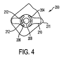
図4は本発明による創傷治療のための装置/パッチ200の代替実施形態を示す。好ましくは、パッチ200は、ヒトの皮膚表面に適合し接着することができる可撓性、装着型パッチ200である。図4から見ることができるように、パッチ200は、さらに、それらの間のギャップを規定するために互いに離れた関係にあって基部部材210上に支持される、「アノード」として識別される少なくとも一つの第1電極204、「カソード」として識別される少なくとも一つの第2電極206、および少なくとも一つの電源208を含む。第1電極204がアノードとして識別することが可能であり、第2電極206がカソードとして識別することが可能である一方で、当業者は、直流によりこれらの指定を逆にすることが可能であることを理解する。示される実施形態において、基部部材210は剥離ライナー211上に載る。パッチ200は、創部または周辺皮膚/組織にパッチ200が接着することを容易にする接着剤(示されていない)(図1の22に類似の)を備えることが可能である。別の結合手段は可能である。任意に、図4の実施形態が中心電極および二つの周辺電極を含むことが可能であることは注目される。中心電極は電源の上に置くことが可能である。一つの実施例において、中心電極はカソードであることが可能であり、周辺電極はアノードであることが可能である。勿論、上述のように、これらの指定は逆にすることが可能である。
FIG. 4 shows an alternative embodiment of a device /
装置200は、創傷治療における使用に有効であるあらゆる適するサイズおよび形状からなることが可能である。図4は、両側性周辺電極配置を有する丸い装置の一つの非限定実施例を示す。電極204、206は電源208に接続される。一部の好ましい実施形態により電源208は直流(ガルバニ電流)を生み出し、他の実施形態により交流または脈流を生み出す。直流と交流または脈流間の選択は、損傷の性質および程度、および創傷状態における痛みの関与に応じてなされる。
The
図4において、電極204、206両方がヒドロゲル212に限定されないがそれなどの湿潤表面により被覆されることを見ることができる。任意に、ヒドロゲル212などの湿潤表面は、上述のように活性成分を含むことが可能である。電源208上の中心領域は、好ましくは、また、任意に上述のように活性成分を含有することが可能であるヒドロゲル212などの湿潤表面を含む。任意に、電極および中心電源それぞれの上に被覆されるヒドロゲル212などの湿潤表面中に含有される活性成分は、異なる活性成分であることが可能である。
In FIG. 4, it can be seen that both
本明細書において概説される違いは別として図4に示される装置200の構成要素の説明は、図1〜3において上述される通りである。
Apart from the differences outlined herein, the description of the components of the
装置200がキットの一部である代替実施形態において、ヒドロゲルなどの湿潤表面および任意の活性剤は、任意に電極上に予備被覆することは可能でない。こうしたキットにおいて、ヒドロゲルおよび任意の活性剤は個別の構成要素であり、限定するわけではないが、装置200の使用前に充填孔を介して電極上に直接塗布するか、または代わりに直接創部上に塗布するなどのあらゆる適するやり方において塗布または投与することができる。
In an alternative embodiment where the
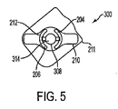
図5は、本発明による創傷治療のための装置/パッチ300の代替実施形態を示す。図5から見ることができるように、装置300は、基板314が装置300中の電源308の中心領域上に配置されると共に、基板が任意にゲル、クリームまたはローションであることが可能であり、任意に活性剤を含有することが可能である導電性担体を吸収することができることを除いて、図4、装置200と同じものである。任意に図5の実施形態が中心電極と二つの周辺電極を含むことが可能であることは、注目される。中心電極は、電源の上に置くことが可能である。一つの実施例において、中心電極はカソードであることが可能であり、周辺電極はアノードであることが可能である。勿論、上述のように、これらの指定は逆にすることが可能である。
FIG. 5 shows an alternative embodiment of a device /
装置300がキットの一部である代替実施形態において、キットは装置および個別構成要素としての導電性担体を含むことが可能である。導電性担体は、任意にゲル、クリームまたはローションであることが可能であり、任意に活性剤を含有することが可能である。好ましくは、導電性担体はヒドロゲルである。こうしたキットにおいて、ヒドロゲルおよび任意の活性剤は、装置300の使用前に充填孔(図5には示されていない)を介して電極および基板上に直接塗布するか、または代わりに直接創部上に塗布することに限定されないがそれらなどのあらゆる適するやり方において塗布または投与することができる。
In an alternative embodiment where the
図6は、本発明による創傷治療のための装置/パッチ400の代替実施形態を示す。好ましくは、パッチ400は、ヒトの皮膚表面に適合し接着することができる可撓性、装着型パッチ400である。図6から見ることができるように、パッチ400は、さらに、それらの間のギャップを規定するために互いに離れた関係にあって基部部材410上に支持される、「アノード」として識別される少なくとも一つの第1電極404、「カソード」として識別される少なくとも一つの第2電極406、および少なくとも一つの電源408を含む。第1電極404がアノードとして識別することが可能であり、第2電極406がカソードとして識別することが可能である一方で、当業者は、直流によりこれらの指定を逆にすることが可能であることを理解する。示される実施形態において、基部部材410は剥離ライナー411上に載る。パッチ400は、創部または周辺皮膚/組織にパッチ400が接着することを容易にする接着剤(示されていない)(図1の22に類似の)を備えることが可能である。別の結合手段は可能である。任意に、図6の実施形態が中心電極および二つの周辺電極を含むことが可能であることは注目される。中心電極は電源の上に置くことが可能である。一つの実施例において、中心電極はカソードであることが可能であり、周辺電極はアノードであることが可能である。勿論、上述のように、これらの指定は逆にすることが可能である。
FIG. 6 shows an alternative embodiment of a device /
装置400は、創傷治療における使用に有効であるあらゆる適するサイズおよび形状からなることが可能である。図6は、両側性電極配置を有する線形装置の一つの非限定実施例を示す。電極404、406は電源408に接続される。一部の好ましい実施形態により電源408は直流(ガルバニ電流)を生み出し、他の実施形態により交流または脈流を生み出す。直流と交流または脈流間の選択は、損傷の性質および程度、および創傷状態における痛みの関与に応じてなされる。
The
図6において、電極404、406の両方がヒドロゲル412に限定されないがそれなどの湿潤表面により被覆されることを見ることができる。任意に、ヒドロゲル412などの湿潤表面は、上述のように活性成分を含むことが可能である。電源408上の中心領域は、好ましくは、また、任意に上述のように活性成分を含有することが可能であるヒドロゲル412などの湿潤表面を含む。任意に、電極および中心電源それぞれの上に被覆されるヒドロゲル412中に含有される活性成分は、異なる活性成分であることが可能である。
In FIG. 6, it can be seen that both
装置400がキットの一部である代替実施形態において、ヒドロゲルなどの湿潤表面および任意の活性剤は、任意に電極上に予備被覆することは可能でない。こうしたキットにおいて、ヒドロゲルおよび任意の活性剤は個別の構成要素であり、限定するわけではないが、装置400の使用前に充填孔を介して電極上に直接塗布するか、または代わりに直接創部上に塗布するなどのあらゆる適するやり方において塗布または投与することができる。
In an alternative embodiment where the
本明細書において概説される違いは別として図6に示される装置400の構成要素の説明は、図1〜3において上述される通りである。
Apart from the differences outlined herein, the description of the components of the
図7は、本発明による創傷治療のための装置/パッチ500の代替実施形態を示す。図7から見ることができるように、装置500は、基板514が装置500中の電源508の中心領域上に配置されると共に、基板が任意にゲル、クリームまたはローションであることが可能であり、任意に活性剤を含有することが可能である導電性担体を吸収することができることを除いて、図6、装置400と同じものである。任意に図7の実施形態が中心電極と二つの周辺電極を含むことが可能であることは、注目される。中心電極は、電源の上に置くことが可能である。一つの実施例において、中心電極はカソードであることが可能であり、周辺電極はアノードであることが可能である。勿論、上述のように、これらの指定は逆にすることが可能である。
FIG. 7 shows an alternative embodiment of a device /
装置500がキットの一部である代替実施形態において、キットは、個別構成要素、装置、および任意にゲル、クリームまたはローションであることが可能であり、任意に活性剤を含有することが可能である導電性担体を含むことが可能である。好ましくは、導電性担体はヒドロゲルである。こうしたキットにおいて、ヒドロゲルおよび任意の活性剤は、限定するわけではないが、装置500の使用前に充填孔(図7には示されていない)を介して電極および基板上に直接塗布するか、または代わりに直接創部上に塗布するなどのあらゆる適するやり方において塗布または投与することができる。
In an alternative embodiment where
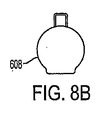
説明を簡略化するために、図8は3部で示される。図8Aは本発明の実施形態による創傷治療装置の構成要素の略図である。図8Bは本発明の実施形態による電源の外形の略図である。図8Cは本発明の実施形態による図8Aおよび8Bの組合せ図からなる創傷治療装置の略図である。図8Cにおいて、電源の表示は、創傷治療装置の他の構成要素との関連でその位置を識別するために影付きで示す。本明細書において用いられる図8への参照とは、図8A、8Bおよび8Cのいずれかまたはすべてに対する参照を含む。 To simplify the description, FIG. 8 is shown in three parts. FIG. 8A is a schematic diagram of components of a wound treatment device according to an embodiment of the present invention. FIG. 8B is a schematic diagram of an outline of a power supply according to an embodiment of the present invention. FIG. 8C is a schematic illustration of a wound treatment device consisting of the combined view of FIGS. 8A and 8B according to an embodiment of the present invention. In FIG. 8C, the power supply indication is shaded to identify its location in relation to other components of the wound treatment device. As used herein, reference to FIG. 8 includes reference to any or all of FIGS. 8A, 8B and 8C.
図8は、本発明による創傷治療のための装置/パッチ600の代替実施形態を示す。好ましくは、パッチ600は、ヒトの皮膚表面に適合し接着することができる可撓性、装着型パッチ600である。図8から見ることができるように、パッチ600は、さらに、それらの間のギャップ612を規定するために互いに離れた関係にあって基部部材610上に支持される、「アノード」として識別される少なくとも一つの第1電極604、「カソード」として識別される少なくとも一つの第2電極606、および少なくとも一つの電源608を含む。第1電極604がアノードとして識別することが可能であり、第2電極606がカソードとして識別することが可能である一方で、当業者は、直流によりこれらの指定を逆にすることが可能であることを理解する。
FIG. 8 shows an alternative embodiment of a device /
装置600は創傷治療での使用に有効であるあらゆる適するサイズおよび形状からなることが可能である。図8はラビリンス電極配置を有する装置の一つの非限定実施例を示す。こうした電極のラビリンス配置は、容易に均一電流分布を促進する。電極604、606は電源608に接続される。一部の好ましい実施形態により電源608は直流(ガルバニ電流)を生み出し、他の実施形態において交流または脈流を生み出す。直流と交流または脈流間の選択は、損傷の性質および程度、および創傷状態における痛みの関与に応じてなされる。
The
好ましくは、電極604、606の一つは亜鉛電極である。好ましくは、こうしたラビリンス型配置において、導電性流体/ゲル614は、二つの電極604、606間の境界面領域612中に収納される。こうした電極構造は、その場で生成される亜鉛イオンによる表面治療用に設定される。電極604、606間のギャップ612を調整することにより、電離療法と表面治療の比率を制御することは可能である。
Preferably, one of the
図8において、導電性流体/ゲル(湿潤表面)および活性物質を含む配合物を保持するための基板616は、電極および境界面領域612がヒドロゲル614に限定されないがそれなどの湿潤表面により被覆されるように電極604、606両方の上に置かれることを、見ることができる。代替実施形態(図8には示されていない)において、装置600は配合物を保持するための基板616を含まない。こうした実施形態において、両方の電極および電極間の境界面領域は、ヒドロゲルなどの湿潤表面により被覆される。
In FIG. 8, a substrate 616 for holding a formulation comprising a conductive fluid / gel (wetting surface) and an active agent is coated with a wetting surface such as but not limited to electrodes and
図8に示される装置600は、電流刺激、湿潤表面治療、亜鉛イオンによる表面治療、亜鉛イオンによる皮膚治療、および最適活性剤による治療による創傷治癒を容易に促進するように設定される。
The
図9は、基部部材703上に置かれる複数の電気作動装置702を含む本発明の創傷治療用装置700の実施形態を示す。図8から見ることができるように、装置は三つの電気作動装置702を含む。装置は任意にあらゆる適する数の電気作動装置702を含むことができる。各電気作動装置702は、任意に電極704、706の同じかまたは異なる配置を含むことができると共に、例えば一つの装置の電源708は任意に線形装置であることができ、一つの装置702は両側性電極配置を有する丸い装置であることができるか、または一つの装置702は同心電極配置を有することができる。こうした装置700は、容易に、単一電極システム装置よりも大きな表面積に効果を及ぼすことを促進する。複数の電気作動装置702のそれぞれは、任意に、異なるかまたは同じの任意の活性剤を含むことが可能である。複数の電気作動装置のそれぞれは、任意に湿潤表面を含むことが可能である。複数の電気作動装置のそれぞれは、任意に、湿潤表面および/または吸収性基板および/または活性物質のあらゆる組合せを含むことが可能である。
FIG. 9 illustrates an embodiment of a
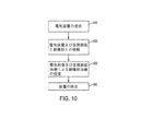
図10は本発明の実施形態による工程系統図である。工程系統図は、完全に集積されたパッチ装置を用いる方法、またはパッチ装置を含むキットを用いる方法に適用される。パッチなどの電気装置は提供することが可能である810。好ましくは、電気装置は、それらの間のギャップを規定するために互いに離れた関係にあって基部部材上に支持される、少なくとも一つの第1電極、および少なくとも一つの第2電極、および少なくとも一つの電源を含む。パッチは電流を提供することを容易にするように設定することが可能である。 FIG. 10 is a process flow diagram according to the embodiment of the present invention. The process flow diagram applies to a method using a fully integrated patch device or a method using a kit including the patch device. Electrical devices such as patches can be provided 810. Preferably, the electrical device has at least one first electrode and at least one second electrode and at least one supported on the base member in spaced relation to each other to define a gap therebetween. Including one power supply. The patch can be configured to facilitate providing current.
対象は、創傷患部を電気装置および湿潤表面および任意に追加の活性物質と接触させることが可能である820。パッチがキットの一部である実施形態において、ヒドロゲルおよび任意の活性物質は、任意に、あらゆる適するやり方で電極および/または基板上に被覆または充填することが可能であるか、または、代わりにまたは加えて直接創面上に塗布することができる。代替実施形態において、電気装置は、電気刺激を通してのみ創傷治癒を提供するために、湿潤表面なしで単独に用いられる。好ましくは、電気装置は、身体の輪郭に適合すると共に、創面および/または周辺領域への容易な接着のための結合手段を含む薄くて可撓性のある装置である。 The subject can contact 820 the wound site with an electrical device and a moist surface and optionally additional active agents. In embodiments where the patch is part of a kit, the hydrogel and any active agent can optionally be coated or filled on the electrode and / or substrate in any suitable manner, or alternatively or In addition, it can be applied directly onto the wound surface. In an alternative embodiment, the electrical device is used alone without a moist surface to provide wound healing only through electrical stimulation. Preferably, the electrical device is a thin and flexible device that conforms to the contours of the body and includes a coupling means for easy adhesion to the wound surface and / or surrounding area.
好ましくは、対象は、電気刺激による創傷治療を促進すると共に、湿潤表面による創傷治癒を促進する830。装置が活性物質を含む場合、電気刺激は、好ましくは、その治療効果を及ぼすために活性物質の送達を促進する。 Preferably, the subject promotes wound healing with electrical stimulation and promotes wound healing with a wet surface 830. If the device includes an active agent, electrical stimulation preferably facilitates delivery of the active agent to exert its therapeutic effect.
装置は治療期間の終わりに身体部分から除去される840。治療期間は変えることができる。装置は、好ましくは、電極が使い果たされるか、あるいは湿潤表面または活性物質が使い果たされるのに要する時間に応じて任意に予定するかまたは決めることができる一定期間後に、創部および/または創部領域との接触から除去される。あるいは、装置は、創傷が治癒してしまうか、またはそれ以上の改善が全く見ることができなくなるといった十分な治療効果まで創傷と接触される。 The device is removed 840 from the body part at the end of the treatment period. The duration of treatment can vary. The device preferably has a wound and / or wound area after a period of time that can be arbitrarily scheduled or determined depending on the time it takes for the electrode to be used up or the wet surface or active substance to be used up. Removed from contact with. Alternatively, the device is contacted with the wound to a sufficient therapeutic effect such that the wound heals or no further improvement can be seen.
治療は、任意に一回の治療であることができるか、または適する時間間隔であらゆる適する回数を繰り返すことができる。 The treatment can optionally be a single treatment, or can be repeated any suitable number of times at suitable time intervals.
従って、一つの実施形態により、キットは連続して用いることができ、それによって、限定しないが、ヒドロゲルなどの湿潤物質および活性剤は最初に塗布することが可能であり、次にパッチを貼り付ける。なお、同じ発明の別の実施形態により、湿潤物質および任意の活性剤は単独使用装置上に位置付けられ、皮膚の目標領域上への装置の貼り付けと同時に適用することが可能である。 Thus, according to one embodiment, the kit can be used sequentially, whereby, without limitation, a wetting substance such as a hydrogel and an active agent can be applied first and then a patch is applied. . It should be noted that according to another embodiment of the same invention, the wetting substance and optional active agent are positioned on a single use device and can be applied simultaneously with the application of the device onto the target area of the skin.
当業者は、これまでの説明から、本発明の実施形態の幅広い技術が多様な形態で実施することができることを理解することができる。従って、本発明の実施形態はその特定実施例と関連して説明されてきたが、一方で、本発明の実施形態の真の範囲は、他の修正が図面、明細書、および特許請求の範囲の研究に際して当業者に明らかになるので、そのように限定されるべきでない。 Those skilled in the art can appreciate from the foregoing description that the broad techniques of the embodiments of the present invention can be implemented in a variety of forms. Thus, while embodiments of the invention have been described with reference to specific examples thereof, the true scope of the embodiments of the invention is not limited to the drawings, specification, and claims. And should not be so limited as will be apparent to those skilled in the art.
Claims (60)
第1端子が前記第1電極に連結される、第1および第2端子を有する少なくとも一つの電源、
前記電源の前記第2端子に連結される少なくとも一つの第2電極、および
前記第1電極、第2電極、および電源を支持する基部部材、
を含む少なくとも一つの電気パッチ、および
少なくとも一つの電気パッチに接続されるかまたはそれと統合して形成される少なくとも一つの湿潤表面、
を含む創傷治療のための装置。 At least one first electrode;
At least one power source having first and second terminals, wherein a first terminal is coupled to the first electrode;
At least one second electrode coupled to the second terminal of the power source; and the first electrode, the second electrode, and a base member supporting the power source,
At least one electrical patch comprising, and at least one wet surface formed or connected to at least one electrical patch,
A device for wound treatment comprising:
不溶性負極の第1層、
不溶性正極の第2層、および
前記第1および第2層の間に配置される水性電解質の第3層、
を含む電気化学セルである、請求項11に記載の装置。 The power source is
A first layer of an insoluble negative electrode,
A second layer of an insoluble positive electrode, and a third layer of an aqueous electrolyte disposed between the first and second layers,
The apparatus of claim 11, wherein the apparatus is an electrochemical cell comprising:
所定のイオン伝導率を得るための電気活性可溶性材料、および
前記第1および第2層を前記第3層に接着するために必要な粘度を得るための水溶性ポリマー、
の少なくとも一つをさらに含む、請求項12に記載の装置。 A deliquescent material for keeping the open cell wet at all times,
An electroactive soluble material for obtaining a predetermined ionic conductivity, and a water-soluble polymer for obtaining a viscosity necessary for adhering the first and second layers to the third layer;
The apparatus of claim 12, further comprising at least one of:
第1端子が前記第1電極に連結される、第1および第2端子を有する少なくとも一つの電源、
前記電源の第2端子に連結される少なくとも一つの第2電極、
前記第1電極、第2電極、および電源を支持する基部部材、
を含む少なくとも一つの電気パッチ、および
パッチから創部への電流を導くための導電性境界面、
を含む創傷治療のための薄くて可撓性の装置。 At least one first electrode;
At least one power source having first and second terminals, wherein a first terminal is coupled to the first electrode;
At least one second electrode coupled to the second terminal of the power source;
A base member supporting the first electrode, the second electrode, and the power source;
At least one electrical patch comprising: a conductive interface for conducting current from the patch to the wound;
Thin and flexible device for wound treatment comprising:
第1端子が前記第1電極に連結される、第1および第2端子を有する少なくとも一つの電源、
前記電源の第2端子に連結される少なくとも一つの第2電極、および
前記第1電極、第2電極、および電源を支持する基部部材、
を含む少なくとも一つの電気パッチを含むと共に、前記第1電極、第2電極および電源が基部部材上に印刷される、創傷治療のための完全に印刷された薄くて可撓性の装置。 At least one first electrode;
At least one power source having first and second terminals, wherein a first terminal is coupled to the first electrode;
At least one second electrode coupled to the second terminal of the power source; and the first electrode, the second electrode, and a base member supporting the power source,
A fully printed thin and flexible device for wound treatment comprising at least one electrical patch comprising: and wherein the first electrode, second electrode and power source are printed on a base member.
第1端子が該第1電極に連結される、第1および第2端子を有する少なくとも一つの電源、
前記電源の第2端子に連結される少なくとも一つの第2電極、および
前記第1電極、第2電極、および電源を支持する基部部材、
を含む少なくとも一つの電気パッチ、および
導電性媒体が活性亜鉛電極と第2電極間のギャップ中に置かれ、表面創傷治療および創傷の電離療法のためのその場での亜鉛イオンの生成を容易に促進する、パッチと創部間の導電性境界面を提供するための導電性媒体、
を含む、創傷治療のための薄くて可撓性の装置。 At least one active zinc electrode,
At least one power source having first and second terminals, wherein a first terminal is coupled to the first electrode;
At least one second electrode coupled to the second terminal of the power source; and the first electrode, the second electrode, and a base member supporting the power source,
At least one electrical patch comprising a conductive medium is placed in the gap between the active zinc electrode and the second electrode to facilitate in situ zinc ion generation for surface wound treatment and wound ionization therapy An electrically conductive medium for providing a conductive interface between the patch and the wound;
A thin and flexible device for wound treatment comprising:
第1端子が前記第1電極に連結される、第1および第2端子を有する少なくとも一つの電源、
前記電源の第2端子に連結される少なくとも一つの第2電極、および
前記第1電極、第2電極、および電源を支持する基部部材、
を含む少なくとも一つの電気パッチ、および
少なくとも一つの湿潤表面、
を含む、創傷治療のためのキット。 At least one first electrode;
At least one power source having first and second terminals, wherein a first terminal is coupled to the first electrode;
At least one second electrode coupled to the second terminal of the power source; and the first electrode, the second electrode, and a base member supporting the power source,
At least one electrical patch comprising, and at least one wet surface,
A kit for wound treatment comprising:
請求項1に記載の装置および付着される湿潤表面を身体患部と接触させ、
電気的に創面を刺激し創面を湿潤表面により処置し、および
装置を創面から除去すること、
を含む、創傷治療の方法。 Select the body part with the wound that is desired to be treated,
Contacting the device of claim 1 and the wet surface to be adhered to a body affected area;
Electrically stimulating the wound surface, treating the wound surface with a moist surface, and removing the device from the wound surface;
A method of wound treatment comprising:
請求項56に記載の創傷治療用のキットを提供し、
請求項58による湿潤表面を塗布し、
装置および付着される湿潤表面を身体患部と接触させ、
電気的に創面を刺激し創面を湿潤表面により処置し、および
装置を創面から除去すること、
を含む、創傷治療の方法。 Select the body part with the wound that is desired to be treated,
A wound treatment kit according to claim 56 is provided,
Applying a wet surface according to claim 58;
Bringing the device and the wet surface to be adhered into contact with the affected body,
Electrically stimulating the wound surface, treating the wound surface with a moist surface, and removing the device from the wound surface;
A method of wound treatment comprising:
Applications Claiming Priority (2)
| Application Number | Priority Date | Filing Date | Title |
|---|---|---|---|
| US50140203P | 2003-09-10 | 2003-09-10 | |
| PCT/IL2004/000821 WO2005023361A2 (en) | 2003-09-10 | 2004-09-09 | Disposable electric bandage |
Publications (2)
| Publication Number | Publication Date |
|---|---|
| JP2007504882A true JP2007504882A (en) | 2007-03-08 |
| JP2007504882A5 JP2007504882A5 (en) | 2007-09-20 |
Family
ID=34273043
Family Applications (1)
| Application Number | Title | Priority Date | Filing Date |
|---|---|---|---|
| JP2006526003A Pending JP2007504882A (en) | 2003-09-10 | 2004-09-09 | Disposable electric bandage |
Country Status (4)
| Country | Link |
|---|---|
| US (1) | US7922676B2 (en) |
| EP (1) | EP1673139A2 (en) |
| JP (1) | JP2007504882A (en) |
| WO (1) | WO2005023361A2 (en) |
Cited By (6)
| Publication number | Priority date | Publication date | Assignee | Title |
|---|---|---|---|---|
| KR20160118622A (en) * | 2015-04-02 | 2016-10-12 | 김상유 | plasma band |
| JP2017505188A (en) * | 2014-02-04 | 2017-02-16 | ロレアル | Electric mask containing at least two compartments |
| JP2017537704A (en) * | 2014-12-05 | 2017-12-21 | エヌエムアール テクノロジー アーエス | Electrochemical device that emits ions |
| KR101915697B1 (en) | 2015-11-23 | 2018-11-06 | 유한실 | Patch-type eletrical stimulation apparatus capable of delivering drug and controlling method thereof |
| JP7287730B2 (en) | 2021-10-12 | 2023-06-06 | ローバル株式会社 | High-concentration zinc dust paint that can inactivate viruses |
| JP7434163B2 (en) | 2018-03-05 | 2024-02-20 | ニューロスティム オーエービー インコーポレイテッド | non-invasive nerve stimulation |
Families Citing this family (134)
| Publication number | Priority date | Publication date | Assignee | Title |
|---|---|---|---|---|
| GB0325129D0 (en) | 2003-10-28 | 2003-12-03 | Smith & Nephew | Apparatus in situ |
| US7457667B2 (en) * | 2004-02-19 | 2008-11-25 | Silverleaf Medical Products, Inc. | Current producing surface for a wound dressing |
| US7662176B2 (en) | 2004-02-19 | 2010-02-16 | Vomaris Innovations, Inc. | Footwear apparatus and methods of manufacture and use |
| US8722235B2 (en) | 2004-04-21 | 2014-05-13 | Blue Spark Technologies, Inc. | Thin printable flexible electrochemical cell and method of making the same |
| US20100069813A1 (en) * | 2004-07-15 | 2010-03-18 | Crisp William E | Wound dressings |
| US20090227930A1 (en) * | 2004-07-15 | 2009-09-10 | Crisp William E | Hygiene materials and absorbents |
| US7495146B2 (en) * | 2004-07-15 | 2009-02-24 | Vivo Ltd. Partnership | Wound dressing |
| US20060015052A1 (en) * | 2004-07-15 | 2006-01-19 | Crisp William E | Wound dressing |
| GB2422549A (en) | 2005-02-01 | 2006-08-02 | Wound Solutions Ltd | Flexible electrodes comprising a honey-comb mesh and integrated wound stimulation treatment devices |
| US20060210613A1 (en) * | 2005-03-15 | 2006-09-21 | Carliss Richard D | Therapeutic wound care product |
| US8029927B2 (en) | 2005-03-22 | 2011-10-04 | Blue Spark Technologies, Inc. | Thin printable electrochemical cell utilizing a “picture frame” and methods of making the same |
| US8722233B2 (en) | 2005-05-06 | 2014-05-13 | Blue Spark Technologies, Inc. | RFID antenna-battery assembly and the method to make the same |
| US7182739B2 (en) * | 2005-05-12 | 2007-02-27 | S.C. Johnson & Son, Inc. | Therapy patch |
| US7300409B2 (en) * | 2005-05-12 | 2007-11-27 | S.C. Johnson & Son, Inc. | Therapy patch |
| CA2610460C (en) | 2005-06-03 | 2015-11-24 | Prezacor, Inc. | Compositions comprising elemental metals and uses therefor |
| US20070023291A1 (en) * | 2005-07-15 | 2007-02-01 | Sai Bhavaraju | Metal Trap |
| JP2009509570A (en) | 2005-09-07 | 2009-03-12 | タイコ ヘルスケア グループ リミテッド パートナーシップ | Self-contained wound care device |
| CA2619925A1 (en) | 2005-09-07 | 2007-03-15 | Tyco Healthcare Group Lp | Wound dressing with vacuum reservoir |
| EP1774987A1 (en) * | 2005-10-12 | 2007-04-18 | Pierenkemper GmbH | Elektrode for nerve and/or muscle stimulation and method for nerve and/or muscle stimulation |
| US20070203534A1 (en) * | 2006-02-13 | 2007-08-30 | Robert Tapper | Stimulating galvanic or slow AC current for therapeutic physiological effects |
| WO2007099538A2 (en) * | 2006-02-28 | 2007-09-07 | Power Paper Ltd | Multi-function electrode and uses thereof |
| US7779625B2 (en) | 2006-05-11 | 2010-08-24 | Kalypto Medical, Inc. | Device and method for wound therapy |
| WO2009098696A2 (en) * | 2008-02-10 | 2009-08-13 | Empire Bio-Medical Devices Inc. | Device and method for enhanced wound treatment |
| US20080008734A1 (en) * | 2006-07-05 | 2008-01-10 | Perrault James J | Reduction of skin irritation caused by biomedical electrodes |
| US20080027509A1 (en) * | 2006-07-28 | 2008-01-31 | Biofisica Llc | Apparatus and methods for facilitating wound healing and treating skin |
| US20080122582A1 (en) * | 2006-11-29 | 2008-05-29 | Texas Instruments Incorporated | Location Based Portable Device Feature Disabler |
| CA2676991A1 (en) * | 2007-01-31 | 2008-08-07 | Adam Heller | Methods and compositions for the treatment of pain |
| EP2115331A1 (en) * | 2007-03-07 | 2009-11-11 | Siemens Aktiengesellschaft | Device and method for producing a seal |
| EP2176814A4 (en) | 2007-07-18 | 2012-06-13 | Blue Spark Technologies Inc | Integrated electronic device and methods of making the same |
| US20090048651A1 (en) * | 2007-08-17 | 2009-02-19 | Biofisica Inc. | Medical electrode systems and methods |
| US20090048504A1 (en) * | 2007-08-17 | 2009-02-19 | Biofisica Inc. | Medical electrode systems and methods |
| AU2008327660B2 (en) | 2007-11-21 | 2014-02-13 | Smith & Nephew Plc | Wound dressing |
| HUE041864T2 (en) | 2007-11-21 | 2019-06-28 | Smith & Nephew | Wound dressing |
| US8118857B2 (en) * | 2007-11-29 | 2012-02-21 | Boston Scientific Corporation | Medical articles that stimulate endothelial cell migration |
| US8574754B2 (en) | 2007-12-19 | 2013-11-05 | Blue Spark Technologies, Inc. | High current thin electrochemical cell and methods of making the same |
| CA2711620A1 (en) | 2008-01-08 | 2009-07-16 | Bluesky Medical Group Inc. | Sustained variable negative pressure wound treatment and method of controlling same |
| AU2009223037A1 (en) | 2008-03-12 | 2009-09-17 | Smith & Nephew Plc | Negative pressure dressing and method of using same |
| KR100950584B1 (en) * | 2008-04-07 | 2010-04-01 | 주식회사로케트전기 | Patch with Battery for Iontophoresis |
| WO2009144615A1 (en) * | 2008-05-26 | 2009-12-03 | Koninklijke Philips Electronics N.V. | Moisture control within a multi-electrode patch for monitoring and electrical stimulation of wound healing |
| CN102159205A (en) * | 2008-06-25 | 2011-08-17 | Fe3医学有限公司 | Patches and methods for the transdermal delivery of a therapeutically effective amount of iron |
| JP5676445B2 (en) * | 2008-08-01 | 2015-02-25 | エヌディーアイ メディカル, エルエルシー | Portable assembly, system and method for providing functional or therapeutic neural stimulation |
| WO2010040357A1 (en) * | 2008-10-06 | 2010-04-15 | Coloplast A/S | Electrical wound dressing having multiple cathodes |
| JP5385582B2 (en) * | 2008-10-10 | 2014-01-08 | 大学共同利用機関法人自然科学研究機構 | Pain sensory nerve stimulator |
| US20100204752A1 (en) * | 2009-02-10 | 2010-08-12 | Tyco Healthcare Group Lp | Negative Pressure and Electrostimulation Therapy Apparatus |
| US8190252B2 (en) | 2009-02-12 | 2012-05-29 | Incube Labs, Llc | Iontophoretic system for transdermal delivery of active agents for therapeutic and medicinal purposes |
| US8961492B2 (en) | 2009-02-12 | 2015-02-24 | Incube Labs, Llc | System and method for controlling the iontophoretic delivery of therapeutic agents based on user inhalation |
| US8348922B2 (en) * | 2009-02-12 | 2013-01-08 | Incube Labs, Llc | Method and apparatus for oscillatory iontophoretic transdermal delivery of a therapeutic agent |
| US8821945B2 (en) * | 2009-04-25 | 2014-09-02 | Fe3 Medical, Inc. | Method for transdermal iontophoretic delivery of chelated agents |
| US8417330B2 (en) * | 2009-06-26 | 2013-04-09 | Incube Labs, Llc | Corrosion resistant electrodes for iontophoretic transdermal delivery devices and methods of use |
| US8903485B2 (en) * | 2009-08-06 | 2014-12-02 | Incube Labs, Llc | Patch and patch assembly for iontophoretic transdermal delivery of active agents for therapeutic and medicinal purposes |
| US8685038B2 (en) | 2009-12-07 | 2014-04-01 | Incube Labs, Llc | Iontophoretic apparatus and method for marking of the skin |
| GB201001631D0 (en) | 2010-02-01 | 2010-03-17 | Eumedic Ltd | Treatment patch electrode for applying electrical impulses to the body of a patient |
| US8986279B2 (en) | 2010-02-10 | 2015-03-24 | Incube Labs, Llc | Methods and architecture for power optimization of iontophoretic transdermal drug delivery |
| WO2011163673A2 (en) * | 2010-06-25 | 2011-12-29 | Purdue Research Foundation | System and method for prevention of hypertrophic scars by actuable patch |
| US9265665B2 (en) * | 2010-07-19 | 2016-02-23 | Kci Licensing, Inc. | Inflatable off-loading wound dressing assemblies, systems, and methods |
| US9017256B2 (en) | 2010-09-22 | 2015-04-28 | Milieu Institute, Llc | System and method for physiological monitoring |
| US9114258B2 (en) | 2011-01-04 | 2015-08-25 | Kato Medical Systems Llc | Electrokinetic nerve stimulator |
| AU2012230701B2 (en) | 2011-03-24 | 2016-09-29 | Incube Labs, Llc | System and method for biphasic transdermal iontophoretic delivery of therapeutic agents |
| WO2012154704A2 (en) | 2011-05-06 | 2012-11-15 | Incube Labs, Llc | System and method for biphasic transdermal iontophoretic delivery of therapeutic agents for the control of addictive cravings |
| WO2013044224A2 (en) | 2011-09-22 | 2013-03-28 | Blue Spark Technologies, Inc. | Cell attachment method |
| EP2780071A4 (en) * | 2011-11-16 | 2015-08-12 | Bodyflow Internat Pty Ltd | Method of reducing hospital stay after surgery |
| JP2015503425A (en) | 2012-01-16 | 2015-02-02 | テキソ メディカル アーペーエス | Devices for the treatment of wounds |
| CN104684595B (en) | 2012-03-12 | 2017-08-04 | 史密夫及内修公开有限公司 | Decompressor and method |
| WO2013177202A1 (en) | 2012-05-21 | 2013-11-28 | Blue Spark Technologies, Inc. | Multi-cell battery |
| US9782082B2 (en) | 2012-11-01 | 2017-10-10 | Blue Spark Technologies, Inc. | Body temperature logging patch |
| US9444078B2 (en) | 2012-11-27 | 2016-09-13 | Blue Spark Technologies, Inc. | Battery cell construction |
| US9295854B2 (en) | 2012-11-28 | 2016-03-29 | Point Source, Inc. | Light and bioelectric therapy pad |
| US10905894B2 (en) | 2013-03-15 | 2021-02-02 | Prezacor, Inc. | Therapeutic bioelectromagnetic fields, pain relief devices, and related methods |
| CN105451696A (en) | 2013-05-02 | 2016-03-30 | 沃莫瑞斯创新公司 | Expandable wound dressings |
| US20180154146A1 (en) | 2013-05-30 | 2018-06-07 | NeurostimOAB, Inc. | Non-invasive nerve stimulation |
| KR102363552B1 (en) | 2013-05-30 | 2022-02-15 | 그라함 에이치. 크리시 | Topical neurological stimulation |
| US20180200514A1 (en) * | 2013-05-30 | 2018-07-19 | Neurostim Oab, Inc. | Non-invasive nerve stimulation |
| US11712557B2 (en) | 2013-05-30 | 2023-08-01 | Neurostim Technologies Llc | Detection and treatment of obstructive sleep apnea |
| US11229789B2 (en) | 2013-05-30 | 2022-01-25 | Neurostim Oab, Inc. | Neuro activator with controller |
| DE102013011141A1 (en) | 2013-07-03 | 2015-01-08 | Dräger Medical GmbH | Measuring device for measuring a body function and method for operating such a measuring device |
| KR101369409B1 (en) * | 2013-07-09 | 2014-03-03 | 김춘기 | Microcurrent generator and electricity |
| US9433785B2 (en) * | 2013-10-21 | 2016-09-06 | Garth Howard Holding | Healing disc, a pain management assembly incorporating the disc, and a method of using the same |
| FR3017054B1 (en) * | 2014-02-04 | 2016-01-22 | Oreal | ELECTRIC MASK COMPRISING AT LEAST TWO COMPARTMENTS |
| US9496582B1 (en) * | 2014-03-24 | 2016-11-15 | Amazon Technologies, Inc. | Flexible battery |
| CN107073259B (en) * | 2014-09-08 | 2021-03-02 | 法斯特麦德意大利有限公司 | Patch capable of generating micro current |
| US9693689B2 (en) | 2014-12-31 | 2017-07-04 | Blue Spark Technologies, Inc. | Body temperature logging patch |
| US11077301B2 (en) | 2015-02-21 | 2021-08-03 | NeurostimOAB, Inc. | Topical nerve stimulator and sensor for bladder control |
| HUE049136T2 (en) | 2015-04-27 | 2020-08-28 | Smith & Nephew | Reduced pressure apparatuses |
| AU2016343674C1 (en) | 2015-10-30 | 2021-06-10 | Aatru Medical, LLC | Wound therapy device and method |
| US20190038472A1 (en) * | 2016-02-08 | 2019-02-07 | Vomaris Innovations, Inc. | Composite bioelectric devices and methods of use |
| WO2017153357A1 (en) | 2016-03-07 | 2017-09-14 | Smith & Nephew Plc | Wound treatment apparatuses and methods with negative pressure source integrated into wound dressing |
| UY36936A (en) | 2016-03-31 | 2017-11-30 | Medecell S A | PROCESS FOR ESTABLISHING AN ELECTRO-STIMULATION PROTOCOL, AND THE RESPECTIVE ELECTRO-STIMULATION PORTABLE EQUIPMENT USING THE REFERRED PROTOCOL |
| US11285047B2 (en) | 2016-04-26 | 2022-03-29 | Smith & Nephew Plc | Wound dressings and methods of use with integrated negative pressure source having a fluid ingress inhibition component |
| CN109069710B (en) | 2016-05-03 | 2022-04-12 | 史密夫及内修公开有限公司 | Optimizing power delivery to a negative pressure source in a negative pressure therapy system |
| JP6975172B2 (en) | 2016-05-03 | 2021-12-01 | スミス アンド ネフュー ピーエルシーSmith & Nephew Public Limited Company | Systems and Methods for Driving Negative Pressure Sources in Negative Pressure Therapy Systems |
| US11096831B2 (en) | 2016-05-03 | 2021-08-24 | Smith & Nephew Plc | Negative pressure wound therapy device activation and control |
| SG11201809829UA (en) | 2016-05-13 | 2018-12-28 | Smith & Nephew | Sensor enabled wound monitoring and therapy apparatus |
| CA3034789A1 (en) | 2016-08-25 | 2018-03-01 | Smith & Nephew Plc | Absorbent negative pressure wound therapy dressing |
| US11564847B2 (en) | 2016-09-30 | 2023-01-31 | Smith & Nephew Plc | Negative pressure wound treatment apparatuses and methods with integrated electronics |
| US20190247234A1 (en) * | 2016-10-21 | 2019-08-15 | Ohio State Innovation Foundation | Antimicrobial wound care dressing |
| US10952907B1 (en) | 2017-02-18 | 2021-03-23 | Tag Off LLC | Acrochordon excising bandage |
| CA3055201A1 (en) | 2017-03-03 | 2018-09-07 | Ohio State Innovation Foundation | Energy generation from fabric electrochemistry |
| EP3592312B1 (en) | 2017-03-08 | 2024-01-10 | Smith & Nephew plc | Negative pressure wound therapy device control in presence of fault condition |
| EP3592212A1 (en) | 2017-03-09 | 2020-01-15 | Smith & Nephew PLC | Wound dressing, patch member and method of sensing one or more wound parameters |
| WO2018162732A1 (en) | 2017-03-09 | 2018-09-13 | Smith & Nephew Plc | Apparatus and method for imaging blood in a target region of tissue |
| AU2018253383A1 (en) | 2017-04-11 | 2019-10-31 | Smith & Nephew Plc | Component positioning and stress relief for sensor enabled wound dressings |
| EP3621667A1 (en) | 2017-05-09 | 2020-03-18 | Smith & Nephew PLC | Redundant controls for negative pressure wound therapy systems |
| AU2018269112A1 (en) | 2017-05-15 | 2019-11-21 | Smith & Nephew Plc | Wound analysis device and method |
| JP7189159B2 (en) | 2017-06-23 | 2022-12-13 | スミス アンド ネフュー ピーエルシー | Sensor placement for sensor-enabled wound monitoring or therapy |
| GB201809007D0 (en) | 2018-06-01 | 2018-07-18 | Smith & Nephew | Restriction of sensor-monitored region for sensor-enabled wound dressings |
| GB201804502D0 (en) | 2018-03-21 | 2018-05-02 | Smith & Nephew | Biocompatible encapsulation and component stress relief for sensor enabled negative pressure wound therapy dressings |
| US10849501B2 (en) | 2017-08-09 | 2020-12-01 | Blue Spark Technologies, Inc. | Body temperature logging patch |
| CA3072006A1 (en) | 2017-08-10 | 2019-02-14 | Smith & Nephew Plc | Positioning of sensors for sensor enabled wound monitoring or therapy |
| GB201804971D0 (en) | 2018-03-28 | 2018-05-09 | Smith & Nephew | Electrostatic discharge protection for sensors in wound therapy |
| GB201718870D0 (en) | 2017-11-15 | 2017-12-27 | Smith & Nephew Inc | Sensor enabled wound therapy dressings and systems |
| EP3681376A1 (en) | 2017-09-10 | 2020-07-22 | Smith & Nephew PLC | Systems and methods for inspection of encapsulation and components in sensor equipped wound dressings |
| GB201718070D0 (en) | 2017-11-01 | 2017-12-13 | Smith & Nephew | Negative pressure wound treatment apparatuses and methods with integrated electronics |
| CA3074780A1 (en) | 2017-09-13 | 2019-03-21 | Smith & Nephew Plc | Negative pressure wound treatment apparatuses and methods with integrated electronics |
| GB201718859D0 (en) | 2017-11-15 | 2017-12-27 | Smith & Nephew | Sensor positioning for sensor enabled wound therapy dressings and systems |
| WO2019063481A1 (en) | 2017-09-27 | 2019-04-04 | Smith & Nephew Plc | Ph sensing for sensor enabled negative pressure wound monitoring and therapy apparatuses |
| EP3687396A1 (en) | 2017-09-28 | 2020-08-05 | Smith & Nephew plc | Neurostimulation and monitoring using sensor enabled wound monitoring and therapy apparatus |
| US11246765B2 (en) | 2017-10-25 | 2022-02-15 | Neurostim Solutions LLC | Smart diaper system |
| US11497653B2 (en) | 2017-11-01 | 2022-11-15 | Smith & Nephew Plc | Negative pressure wound treatment apparatuses and methods with integrated electronics |
| GB201718054D0 (en) | 2017-11-01 | 2017-12-13 | Smith & Nephew | Sterilization of integrated negative pressure wound treatment apparatuses and sterilization methods |
| GB201718072D0 (en) | 2017-11-01 | 2017-12-13 | Smith & Nephew | Negative pressure wound treatment apparatuses and methods with integrated electronics |
| CN111601636A (en) | 2017-11-07 | 2020-08-28 | Oab神经电疗科技公司 | Non-invasive neural activator with adaptive circuit |
| US11305113B2 (en) | 2017-11-11 | 2022-04-19 | Neurostim Solutions LLC | Nocturia reduction system |
| EP3709943A1 (en) | 2017-11-15 | 2020-09-23 | Smith & Nephew PLC | Integrated sensor enabled wound monitoring and/or therapy dressings and systems |
| WO2020053290A1 (en) | 2018-09-12 | 2020-03-19 | Smith & Nephew Plc | Device, apparatus and method of determining skin perfusion pressure |
| USD898925S1 (en) | 2018-09-13 | 2020-10-13 | Smith & Nephew Plc | Medical dressing |
| US20220118253A1 (en) * | 2019-01-18 | 2022-04-21 | Ist, Llc | Systems and methods for craniocervical and auricular neuromodulation |
| US11305110B2 (en) | 2019-03-22 | 2022-04-19 | Neurostim Technologies Llc | Detection and treatment of obstructive sleep apnea |
| US11478638B2 (en) | 2019-03-22 | 2022-10-25 | Neurostim Technologies Llc | Detection and treatment of obstructive sleep apnea |
| CN114126704A (en) | 2019-06-26 | 2022-03-01 | 神经科学技术有限责任公司 | Non-invasive neural activator with adaptive circuit |
| WO2021126921A1 (en) | 2019-12-16 | 2021-06-24 | Neurostim Solutions, Llc | Non-invasive nerve activator with boosted charge delivery |
| US20210267625A1 (en) | 2020-02-28 | 2021-09-02 | Tag Off LLC | Skin Growth Excision Apparatus |
| WO2021185423A1 (en) * | 2020-03-17 | 2021-09-23 | Lempré Aps | Patch for electrical stimulation of skin tissue |
| PL434068A1 (en) * | 2020-05-25 | 2021-11-29 | Prevlly Spółka Z Ograniczoną Odpowiedzialnością | Electrostimulating layered dressing and electrostimulation method |
| CN112843465B (en) * | 2020-12-31 | 2023-09-19 | 北京理工大学 | Portable electric healing plaster and preparation method thereof |
Citations (1)
| Publication number | Priority date | Publication date | Assignee | Title |
|---|---|---|---|---|
| WO2003035166A2 (en) * | 2001-10-24 | 2003-05-01 | Power Paper Ltd. | Dermal patch |
Family Cites Families (8)
| Publication number | Priority date | Publication date | Assignee | Title |
|---|---|---|---|---|
| DE3914662A1 (en) * | 1989-05-03 | 1990-11-08 | Alt Eckhard | DEVICE FOR TRANSMITTING ELECTRICAL SIGNALS BETWEEN AN IMPLANTABLE MEDICAL DEVICE AND ELECTRICALLY EXPENSIBLE HUMAN TISSUE |
| US5652043A (en) | 1995-12-20 | 1997-07-29 | Baruch Levanon | Flexible thin layer open electrochemical cell |
| AU3640997A (en) * | 1996-06-19 | 1998-01-07 | Du Pont Pharmaceuticals Company | Iontophoretic delivery of integrin inhibitors |
| US5961483A (en) * | 1996-06-19 | 1999-10-05 | Sage; Burton H. | Iontophoretic delivery of cell adhesion inhibitors |
| US6246904B1 (en) * | 1996-12-17 | 2001-06-12 | Alza Corporation | Electrotransport drug delivery reservoirs containing inert fillers |
| US5974344A (en) * | 1998-03-02 | 1999-10-26 | Shoemaker, Ii; Charles | Wound care electrode |
| US20030147835A1 (en) * | 2000-06-15 | 2003-08-07 | Munro Hugh Semple | Process for the manufacture of hydrogel compositions and hydrogel compositions manufactured thereby |
| US6560483B1 (en) * | 2000-10-18 | 2003-05-06 | Minnesota High-Tech Resources, Llc | Iontophoretic delivery patch |
-
2004
- 2004-09-09 JP JP2006526003A patent/JP2007504882A/en active Pending
- 2004-09-09 WO PCT/IL2004/000821 patent/WO2005023361A2/en active Application Filing
- 2004-09-09 EP EP04770492A patent/EP1673139A2/en not_active Withdrawn
- 2004-09-09 US US10/936,540 patent/US7922676B2/en not_active Expired - Fee Related
Patent Citations (1)
| Publication number | Priority date | Publication date | Assignee | Title |
|---|---|---|---|---|
| WO2003035166A2 (en) * | 2001-10-24 | 2003-05-01 | Power Paper Ltd. | Dermal patch |
Cited By (7)
| Publication number | Priority date | Publication date | Assignee | Title |
|---|---|---|---|---|
| JP2017505188A (en) * | 2014-02-04 | 2017-02-16 | ロレアル | Electric mask containing at least two compartments |
| JP2017537704A (en) * | 2014-12-05 | 2017-12-21 | エヌエムアール テクノロジー アーエス | Electrochemical device that emits ions |
| KR20160118622A (en) * | 2015-04-02 | 2016-10-12 | 김상유 | plasma band |
| KR101672824B1 (en) | 2015-04-02 | 2016-11-04 | 서재화 | plasma band |
| KR101915697B1 (en) | 2015-11-23 | 2018-11-06 | 유한실 | Patch-type eletrical stimulation apparatus capable of delivering drug and controlling method thereof |
| JP7434163B2 (en) | 2018-03-05 | 2024-02-20 | ニューロスティム オーエービー インコーポレイテッド | non-invasive nerve stimulation |
| JP7287730B2 (en) | 2021-10-12 | 2023-06-06 | ローバル株式会社 | High-concentration zinc dust paint that can inactivate viruses |
Also Published As
| Publication number | Publication date |
|---|---|
| WO2005023361A3 (en) | 2005-04-21 |
| WO2005023361A2 (en) | 2005-03-17 |
| US7922676B2 (en) | 2011-04-12 |
| EP1673139A2 (en) | 2006-06-28 |
| US20050085751A1 (en) | 2005-04-21 |
Similar Documents
| Publication | Publication Date | Title |
|---|---|---|
| JP2007504882A (en) | Disposable electric bandage | |
| RU2372113C2 (en) | Method, apparatus and kit for onychomycosis treatment with using electrokinetic mass transport | |
| KR101100632B1 (en) | A device and topical composition for treating acne and rosacea with electrochemically generated zinc ions | |
| JP4394444B2 (en) | Devices and methods for controlled intradermal delivery of active agents | |
| US7340297B2 (en) | Kit, device and method for controlled delivery of oxidizing agent into the skin | |
| JP3119486B2 (en) | Electrode for iontophoresis and device using the same | |
| JP2005506158A5 (en) | ||
| JP2006526454A5 (en) | ||
| CN1607970A (en) | Dermal patch | |
| KR20060101206A (en) | Methods of treating pores on the skin with electricity | |
| CN1512901A (en) | Transdermal electrotransport delivery device including antimicrobial compatible reservoir composition | |
| JP7255921B2 (en) | iontophoresis administration device | |
| US20100069813A1 (en) | Wound dressings | |
| US20100228180A1 (en) | Power Source Electrode Treatment Device | |
| JPH0852224A (en) | Device for iontophoresis | |
| JPH08173554A (en) | Skin contact therapeutic apparatus | |
| JP2015503425A (en) | Devices for the treatment of wounds | |
| WO2001013988A1 (en) | Devices and methods for the generation of voltage potential | |
| JP2839279B2 (en) | Device for iontophoresis | |
| Anisimov et al. | Development of a portable device for iontophoresis | |
| JPS6131169A (en) | Device for iontophoresis |
Legal Events
| Date | Code | Title | Description |
|---|---|---|---|
| A521 | Request for written amendment filed |
Free format text: JAPANESE INTERMEDIATE CODE: A523 Effective date: 20070718 |
|
| A621 | Written request for application examination |
Free format text: JAPANESE INTERMEDIATE CODE: A621 Effective date: 20070718 |
|
| A131 | Notification of reasons for refusal |
Free format text: JAPANESE INTERMEDIATE CODE: A131 Effective date: 20100202 |
|
| A02 | Decision of refusal |
Free format text: JAPANESE INTERMEDIATE CODE: A02 Effective date: 20100706 |