EP3451983B1 - System zur neuroprotektiven therapie gegen glaukom - Google Patents
System zur neuroprotektiven therapie gegen glaukom Download PDFInfo
- Publication number
- EP3451983B1 EP3451983B1 EP16901155.8A EP16901155A EP3451983B1 EP 3451983 B1 EP3451983 B1 EP 3451983B1 EP 16901155 A EP16901155 A EP 16901155A EP 3451983 B1 EP3451983 B1 EP 3451983B1
- Authority
- EP
- European Patent Office
- Prior art keywords
- treatment
- laser
- retinal
- laser light
- retina
- Prior art date
- Legal status (The legal status is an assumption and is not a legal conclusion. Google has not performed a legal analysis and makes no representation as to the accuracy of the status listed.)
- Active
Links
- 208000010412 Glaucoma Diseases 0.000 title claims description 21
- 238000011859 neuroprotective therapy Methods 0.000 title claims description 4
- 238000011282 treatment Methods 0.000 claims description 258
- 230000002207 retinal effect Effects 0.000 claims description 135
- 210000001525 retina Anatomy 0.000 claims description 111
- 230000003287 optical effect Effects 0.000 claims description 38
- 230000001225 therapeutic effect Effects 0.000 claims description 38
- 230000007246 mechanism Effects 0.000 claims description 22
- 230000000649 photocoagulation Effects 0.000 description 69
- 210000001519 tissue Anatomy 0.000 description 66
- 210000003583 retinal pigment epithelium Anatomy 0.000 description 43
- 238000000034 method Methods 0.000 description 41
- 208000017442 Retinal disease Diseases 0.000 description 31
- 230000006378 damage Effects 0.000 description 29
- 210000004027 cell Anatomy 0.000 description 27
- 230000000694 effects Effects 0.000 description 27
- 238000012360 testing method Methods 0.000 description 27
- 230000006870 function Effects 0.000 description 24
- 210000001328 optic nerve Anatomy 0.000 description 23
- 238000001126 phototherapy Methods 0.000 description 22
- 206010012689 Diabetic retinopathy Diseases 0.000 description 21
- 230000000007 visual effect Effects 0.000 description 21
- 230000004393 visual impairment Effects 0.000 description 21
- 102000002812 Heat-Shock Proteins Human genes 0.000 description 20
- 108010004889 Heat-Shock Proteins Proteins 0.000 description 20
- 230000008901 benefit Effects 0.000 description 19
- 238000002203 pretreatment Methods 0.000 description 19
- 206010030348 Open-Angle Glaucoma Diseases 0.000 description 18
- 206010057430 Retinal injury Diseases 0.000 description 18
- 238000013532 laser treatment Methods 0.000 description 18
- 230000003902 lesion Effects 0.000 description 18
- 230000004304 visual acuity Effects 0.000 description 17
- 230000004410 intraocular pressure Effects 0.000 description 15
- 230000000451 tissue damage Effects 0.000 description 15
- 231100000827 tissue damage Toxicity 0.000 description 15
- XKRFYHLGVUSROY-UHFFFAOYSA-N Argon Chemical compound [Ar] XKRFYHLGVUSROY-UHFFFAOYSA-N 0.000 description 14
- 108090000695 Cytokines Proteins 0.000 description 14
- 102000004127 Cytokines Human genes 0.000 description 14
- 208000037265 diseases, disorders, signs and symptoms Diseases 0.000 description 14
- 230000001976 improved effect Effects 0.000 description 14
- 230000001965 increasing effect Effects 0.000 description 14
- 206010012688 Diabetic retinal oedema Diseases 0.000 description 13
- 201000011190 diabetic macular edema Diseases 0.000 description 13
- 201000010099 disease Diseases 0.000 description 13
- 230000000324 neuroprotective effect Effects 0.000 description 12
- 230000004438 eyesight Effects 0.000 description 11
- 239000000835 fiber Substances 0.000 description 11
- 201000004569 Blindness Diseases 0.000 description 10
- 206010025421 Macule Diseases 0.000 description 10
- 206010064930 age-related macular degeneration Diseases 0.000 description 10
- 208000002780 macular degeneration Diseases 0.000 description 10
- 238000012014 optical coherence tomography Methods 0.000 description 10
- 230000008569 process Effects 0.000 description 10
- 230000006872 improvement Effects 0.000 description 9
- 230000009467 reduction Effects 0.000 description 9
- 230000004044 response Effects 0.000 description 9
- 238000002560 therapeutic procedure Methods 0.000 description 9
- 208000003098 Ganglion Cysts Diseases 0.000 description 8
- 208000005400 Synovial Cyst Diseases 0.000 description 8
- 230000002411 adverse Effects 0.000 description 8
- 230000004243 retinal function Effects 0.000 description 8
- 230000004913 activation Effects 0.000 description 7
- 229910052786 argon Inorganic materials 0.000 description 7
- 238000009826 distribution Methods 0.000 description 7
- 230000017525 heat dissipation Effects 0.000 description 7
- 230000000750 progressive effect Effects 0.000 description 7
- 230000002829 reductive effect Effects 0.000 description 7
- 231100000241 scar Toxicity 0.000 description 7
- 206010061218 Inflammation Diseases 0.000 description 6
- 230000005856 abnormality Effects 0.000 description 6
- 206010012601 diabetes mellitus Diseases 0.000 description 6
- 230000004054 inflammatory process Effects 0.000 description 6
- 231100000518 lethal Toxicity 0.000 description 6
- 230000001665 lethal effect Effects 0.000 description 6
- 210000003994 retinal ganglion cell Anatomy 0.000 description 6
- 208000014139 Retinal vascular disease Diseases 0.000 description 5
- 206010038923 Retinopathy Diseases 0.000 description 5
- 230000005779 cell damage Effects 0.000 description 5
- 230000003915 cell function Effects 0.000 description 5
- 208000037887 cell injury Diseases 0.000 description 5
- 230000007423 decrease Effects 0.000 description 5
- 240000008570 Digitaria exilis Species 0.000 description 4
- 235000005459 Digitaria exilis Nutrition 0.000 description 4
- 238000004458 analytical method Methods 0.000 description 4
- 230000007012 clinical effect Effects 0.000 description 4
- 230000001066 destructive effect Effects 0.000 description 4
- 230000004064 dysfunction Effects 0.000 description 4
- 230000000763 evoking effect Effects 0.000 description 4
- 230000036541 health Effects 0.000 description 4
- 238000003384 imaging method Methods 0.000 description 4
- 238000004519 manufacturing process Methods 0.000 description 4
- 238000013021 overheating Methods 0.000 description 4
- 230000019612 pigmentation Effects 0.000 description 4
- 230000037390 scarring Effects 0.000 description 4
- 206010003694 Atrophy Diseases 0.000 description 3
- 208000002177 Cataract Diseases 0.000 description 3
- 208000001344 Macular Edema Diseases 0.000 description 3
- 206010025415 Macular oedema Diseases 0.000 description 3
- 208000027418 Wounds and injury Diseases 0.000 description 3
- 238000010521 absorption reaction Methods 0.000 description 3
- 238000009825 accumulation Methods 0.000 description 3
- 230000037444 atrophy Effects 0.000 description 3
- 230000008859 change Effects 0.000 description 3
- 210000003161 choroid Anatomy 0.000 description 3
- 230000001684 chronic effect Effects 0.000 description 3
- 238000007796 conventional method Methods 0.000 description 3
- 238000001514 detection method Methods 0.000 description 3
- 238000002571 electroretinography Methods 0.000 description 3
- 208000014674 injury Diseases 0.000 description 3
- 230000003993 interaction Effects 0.000 description 3
- 230000005923 long-lasting effect Effects 0.000 description 3
- 201000010230 macular retinal edema Diseases 0.000 description 3
- 239000013307 optical fiber Substances 0.000 description 3
- 230000036407 pain Effects 0.000 description 3
- 230000001575 pathological effect Effects 0.000 description 3
- 230000000144 pharmacologic effect Effects 0.000 description 3
- 201000007914 proliferative diabetic retinopathy Diseases 0.000 description 3
- 210000001747 pupil Anatomy 0.000 description 3
- 230000008439 repair process Effects 0.000 description 3
- 230000035945 sensitivity Effects 0.000 description 3
- 238000000926 separation method Methods 0.000 description 3
- 230000000638 stimulation Effects 0.000 description 3
- 230000004382 visual function Effects 0.000 description 3
- 238000012935 Averaging Methods 0.000 description 2
- 208000005590 Choroidal Neovascularization Diseases 0.000 description 2
- 206010060823 Choroidal neovascularisation Diseases 0.000 description 2
- 206010061818 Disease progression Diseases 0.000 description 2
- XUMBMVFBXHLACL-UHFFFAOYSA-N Melanin Chemical compound O=C1C(=O)C(C2=CNC3=C(C(C(=O)C4=C32)=O)C)=C2C4=CNC2=C1C XUMBMVFBXHLACL-UHFFFAOYSA-N 0.000 description 2
- 208000036580 Optic nerve cupping Diseases 0.000 description 2
- 206010038848 Retinal detachment Diseases 0.000 description 2
- 208000007014 Retinitis pigmentosa Diseases 0.000 description 2
- 108010073929 Vascular Endothelial Growth Factor A Proteins 0.000 description 2
- 102000005789 Vascular Endothelial Growth Factors Human genes 0.000 description 2
- 108010019530 Vascular Endothelial Growth Factors Proteins 0.000 description 2
- 208000034698 Vitreous haemorrhage Diseases 0.000 description 2
- 230000002159 abnormal effect Effects 0.000 description 2
- 230000004071 biological effect Effects 0.000 description 2
- 230000008512 biological response Effects 0.000 description 2
- 230000001413 cellular effect Effects 0.000 description 2
- 230000004637 cellular stress Effects 0.000 description 2
- 238000011443 conventional therapy Methods 0.000 description 2
- 230000016396 cytokine production Effects 0.000 description 2
- 230000001627 detrimental effect Effects 0.000 description 2
- 230000010339 dilation Effects 0.000 description 2
- 230000005750 disease progression Effects 0.000 description 2
- 229940079593 drug Drugs 0.000 description 2
- 239000003814 drug Substances 0.000 description 2
- 230000005611 electricity Effects 0.000 description 2
- 230000007831 electrophysiology Effects 0.000 description 2
- 238000002001 electrophysiology Methods 0.000 description 2
- 238000005516 engineering process Methods 0.000 description 2
- 238000013534 fluorescein angiography Methods 0.000 description 2
- PCHJSUWPFVWCPO-UHFFFAOYSA-N gold Chemical compound [Au] PCHJSUWPFVWCPO-UHFFFAOYSA-N 0.000 description 2
- 239000010931 gold Substances 0.000 description 2
- 229910052737 gold Inorganic materials 0.000 description 2
- NOESYZHRGYRDHS-UHFFFAOYSA-N insulin Chemical compound N1C(=O)C(NC(=O)C(CCC(N)=O)NC(=O)C(CCC(O)=O)NC(=O)C(C(C)C)NC(=O)C(NC(=O)CN)C(C)CC)CSSCC(C(NC(CO)C(=O)NC(CC(C)C)C(=O)NC(CC=2C=CC(O)=CC=2)C(=O)NC(CCC(N)=O)C(=O)NC(CC(C)C)C(=O)NC(CCC(O)=O)C(=O)NC(CC(N)=O)C(=O)NC(CC=2C=CC(O)=CC=2)C(=O)NC(CSSCC(NC(=O)C(C(C)C)NC(=O)C(CC(C)C)NC(=O)C(CC=2C=CC(O)=CC=2)NC(=O)C(CC(C)C)NC(=O)C(C)NC(=O)C(CCC(O)=O)NC(=O)C(C(C)C)NC(=O)C(CC(C)C)NC(=O)C(CC=2NC=NC=2)NC(=O)C(CO)NC(=O)CNC2=O)C(=O)NCC(=O)NC(CCC(O)=O)C(=O)NC(CCCNC(N)=N)C(=O)NCC(=O)NC(CC=3C=CC=CC=3)C(=O)NC(CC=3C=CC=CC=3)C(=O)NC(CC=3C=CC(O)=CC=3)C(=O)NC(C(C)O)C(=O)N3C(CCC3)C(=O)NC(CCCCN)C(=O)NC(C)C(O)=O)C(=O)NC(CC(N)=O)C(O)=O)=O)NC(=O)C(C(C)CC)NC(=O)C(CO)NC(=O)C(C(C)O)NC(=O)C1CSSCC2NC(=O)C(CC(C)C)NC(=O)C(NC(=O)C(CCC(N)=O)NC(=O)C(CC(N)=O)NC(=O)C(NC(=O)C(N)CC=1C=CC=CC=1)C(C)C)CC1=CN=CN1 NOESYZHRGYRDHS-UHFFFAOYSA-N 0.000 description 2
- 238000001990 intravenous administration Methods 0.000 description 2
- 230000000670 limiting effect Effects 0.000 description 2
- 238000012417 linear regression Methods 0.000 description 2
- 230000033001 locomotion Effects 0.000 description 2
- 230000007774 longterm Effects 0.000 description 2
- 238000007726 management method Methods 0.000 description 2
- 230000001404 mediated effect Effects 0.000 description 2
- 230000004112 neuroprotection Effects 0.000 description 2
- 231100001160 nonlethal Toxicity 0.000 description 2
- 230000004309 orthophoria Effects 0.000 description 2
- 230000000737 periodic effect Effects 0.000 description 2
- 108091008695 photoreceptors Proteins 0.000 description 2
- 230000001179 pupillary effect Effects 0.000 description 2
- 230000004268 retinal thickening Effects 0.000 description 2
- 230000002441 reversible effect Effects 0.000 description 2
- 210000004761 scalp Anatomy 0.000 description 2
- 239000007787 solid Substances 0.000 description 2
- 230000009885 systemic effect Effects 0.000 description 2
- 230000008719 thickening Effects 0.000 description 2
- 230000001052 transient effect Effects 0.000 description 2
- 230000002792 vascular Effects 0.000 description 2
- 230000002227 vasoactive effect Effects 0.000 description 2
- 208000032484 Accidental exposure to product Diseases 0.000 description 1
- 206010005184 Blindness transient Diseases 0.000 description 1
- 244000025254 Cannabis sativa Species 0.000 description 1
- 208000003569 Central serous chorioretinopathy Diseases 0.000 description 1
- 208000033379 Chorioretinopathy Diseases 0.000 description 1
- 206010008783 Choroidal detachment Diseases 0.000 description 1
- 208000032544 Cicatrix Diseases 0.000 description 1
- 102000004877 Insulin Human genes 0.000 description 1
- 108090001061 Insulin Proteins 0.000 description 1
- 208000031471 Macular fibrosis Diseases 0.000 description 1
- 208000028389 Nerve injury Diseases 0.000 description 1
- 208000001140 Night Blindness Diseases 0.000 description 1
- 206010061323 Optic neuropathy Diseases 0.000 description 1
- 208000037111 Retinal Hemorrhage Diseases 0.000 description 1
- 208000007135 Retinal Neovascularization Diseases 0.000 description 1
- 201000007737 Retinal degeneration Diseases 0.000 description 1
- 208000032400 Retinal pigmentation Diseases 0.000 description 1
- 206010038895 Retinal scar Diseases 0.000 description 1
- 208000027073 Stargardt disease Diseases 0.000 description 1
- 208000036038 Subretinal fibrosis Diseases 0.000 description 1
- 206010046851 Uveitis Diseases 0.000 description 1
- 238000002679 ablation Methods 0.000 description 1
- 238000005299 abrasion Methods 0.000 description 1
- 239000000370 acceptor Substances 0.000 description 1
- 231100000818 accidental exposure Toxicity 0.000 description 1
- 230000009471 action Effects 0.000 description 1
- 230000004075 alteration Effects 0.000 description 1
- 238000002583 angiography Methods 0.000 description 1
- 238000013459 approach Methods 0.000 description 1
- QVGXLLKOCUKJST-UHFFFAOYSA-N atomic oxygen Chemical compound [O] QVGXLLKOCUKJST-UHFFFAOYSA-N 0.000 description 1
- 230000010455 autoregulation Effects 0.000 description 1
- 210000003050 axon Anatomy 0.000 description 1
- 230000009286 beneficial effect Effects 0.000 description 1
- 230000005540 biological transmission Effects 0.000 description 1
- 239000008280 blood Substances 0.000 description 1
- 210000004369 blood Anatomy 0.000 description 1
- 210000004204 blood vessel Anatomy 0.000 description 1
- 210000004556 brain Anatomy 0.000 description 1
- 230000015556 catabolic process Effects 0.000 description 1
- 210000003169 central nervous system Anatomy 0.000 description 1
- 238000004140 cleaning Methods 0.000 description 1
- 230000004456 color vision Effects 0.000 description 1
- 238000012790 confirmation Methods 0.000 description 1
- 230000008602 contraction Effects 0.000 description 1
- 238000001816 cooling Methods 0.000 description 1
- 210000004087 cornea Anatomy 0.000 description 1
- 230000008878 coupling Effects 0.000 description 1
- 238000010168 coupling process Methods 0.000 description 1
- 238000005859 coupling reaction Methods 0.000 description 1
- 231100000433 cytotoxic Toxicity 0.000 description 1
- 230000001472 cytotoxic effect Effects 0.000 description 1
- 230000007547 defect Effects 0.000 description 1
- 230000007850 degeneration Effects 0.000 description 1
- 238000006731 degradation reaction Methods 0.000 description 1
- 230000003111 delayed effect Effects 0.000 description 1
- 230000001419 dependent effect Effects 0.000 description 1
- 238000011161 development Methods 0.000 description 1
- 238000010586 diagram Methods 0.000 description 1
- 231100000673 dose–response relationship Toxicity 0.000 description 1
- 238000002651 drug therapy Methods 0.000 description 1
- 208000011325 dry age related macular degeneration Diseases 0.000 description 1
- 230000002497 edematous effect Effects 0.000 description 1
- 238000004070 electrodeposition Methods 0.000 description 1
- 210000000981 epithelium Anatomy 0.000 description 1
- 230000003203 everyday effect Effects 0.000 description 1
- 230000007717 exclusion Effects 0.000 description 1
- 210000001723 extracellular space Anatomy 0.000 description 1
- 208000030533 eye disease Diseases 0.000 description 1
- 230000004424 eye movement Effects 0.000 description 1
- 230000001497 fibrovascular Effects 0.000 description 1
- GNBHRKFJIUUOQI-UHFFFAOYSA-N fluorescein Chemical compound O1C(=O)C2=CC=CC=C2C21C1=CC=C(O)C=C1OC1=CC(O)=CC=C21 GNBHRKFJIUUOQI-UHFFFAOYSA-N 0.000 description 1
- 230000002068 genetic effect Effects 0.000 description 1
- 125000001475 halogen functional group Chemical group 0.000 description 1
- 210000003128 head Anatomy 0.000 description 1
- 238000010438 heat treatment Methods 0.000 description 1
- 230000002008 hemorrhagic effect Effects 0.000 description 1
- 230000013632 homeostatic process Effects 0.000 description 1
- 230000000642 iatrogenic effect Effects 0.000 description 1
- 238000005286 illumination Methods 0.000 description 1
- 238000000338 in vitro Methods 0.000 description 1
- MOFVSTNWEDAEEK-UHFFFAOYSA-M indocyanine green Chemical compound [Na+].[O-]S(=O)(=O)CCCCN1C2=CC=C3C=CC=CC3=C2C(C)(C)C1=CC=CC=CC=CC1=[N+](CCCCS([O-])(=O)=O)C2=CC=C(C=CC=C3)C3=C2C1(C)C MOFVSTNWEDAEEK-UHFFFAOYSA-M 0.000 description 1
- 229960004657 indocyanine green Drugs 0.000 description 1
- 230000001939 inductive effect Effects 0.000 description 1
- 230000028709 inflammatory response Effects 0.000 description 1
- 230000000977 initiatory effect Effects 0.000 description 1
- 229940125396 insulin Drugs 0.000 description 1
- 230000002452 interceptive effect Effects 0.000 description 1
- 230000003834 intracellular effect Effects 0.000 description 1
- 208000010746 intraretinal hemorrhage Diseases 0.000 description 1
- 229910052743 krypton Inorganic materials 0.000 description 1
- DNNSSWSSYDEUBZ-UHFFFAOYSA-N krypton atom Chemical compound [Kr] DNNSSWSSYDEUBZ-UHFFFAOYSA-N 0.000 description 1
- 238000002647 laser therapy Methods 0.000 description 1
- 230000002045 lasting effect Effects 0.000 description 1
- 230000031700 light absorption Effects 0.000 description 1
- 239000004973 liquid crystal related substance Substances 0.000 description 1
- 238000002690 local anesthesia Methods 0.000 description 1
- 208000018769 loss of vision Diseases 0.000 description 1
- 231100000864 loss of vision Toxicity 0.000 description 1
- 238000012423 maintenance Methods 0.000 description 1
- 230000000873 masking effect Effects 0.000 description 1
- 238000005259 measurement Methods 0.000 description 1
- 239000012528 membrane Substances 0.000 description 1
- 230000002503 metabolic effect Effects 0.000 description 1
- 238000013533 micropulse laser treatment Methods 0.000 description 1
- 230000003278 mimic effect Effects 0.000 description 1
- 230000000116 mitigating effect Effects 0.000 description 1
- 230000004048 modification Effects 0.000 description 1
- 238000012986 modification Methods 0.000 description 1
- 238000012544 monitoring process Methods 0.000 description 1
- 230000000877 morphologic effect Effects 0.000 description 1
- 210000005036 nerve Anatomy 0.000 description 1
- 230000008764 nerve damage Effects 0.000 description 1
- 210000005157 neural retina Anatomy 0.000 description 1
- 210000002569 neuron Anatomy 0.000 description 1
- 238000010606 normalization Methods 0.000 description 1
- 238000002577 ophthalmoscopy Methods 0.000 description 1
- 208000020911 optic nerve disease Diseases 0.000 description 1
- 210000000056 organ Anatomy 0.000 description 1
- 230000010355 oscillation Effects 0.000 description 1
- 239000001301 oxygen Substances 0.000 description 1
- 229910052760 oxygen Inorganic materials 0.000 description 1
- 230000008506 pathogenesis Effects 0.000 description 1
- 230000002093 peripheral effect Effects 0.000 description 1
- 230000002688 persistence Effects 0.000 description 1
- 230000002085 persistent effect Effects 0.000 description 1
- 230000000886 photobiology Effects 0.000 description 1
- 230000008375 physiological alteration Effects 0.000 description 1
- 239000000049 pigment Substances 0.000 description 1
- 230000002980 postoperative effect Effects 0.000 description 1
- 230000003389 potentiating effect Effects 0.000 description 1
- 230000002028 premature Effects 0.000 description 1
- 238000002360 preparation method Methods 0.000 description 1
- 201000009015 preretinal fibrosis Diseases 0.000 description 1
- 210000000977 primary visual cortex Anatomy 0.000 description 1
- 208000037821 progressive disease Diseases 0.000 description 1
- 230000035755 proliferation Effects 0.000 description 1
- 230000002035 prolonged effect Effects 0.000 description 1
- 230000004224 protection Effects 0.000 description 1
- 230000001681 protective effect Effects 0.000 description 1
- 230000006432 protein unfolding Effects 0.000 description 1
- 102000004169 proteins and genes Human genes 0.000 description 1
- 108090000623 proteins and genes Proteins 0.000 description 1
- 230000005855 radiation Effects 0.000 description 1
- 230000007115 recruitment Effects 0.000 description 1
- 230000003252 repetitive effect Effects 0.000 description 1
- 238000011160 research Methods 0.000 description 1
- 230000004258 retinal degeneration Effects 0.000 description 1
- 230000004264 retinal detachment Effects 0.000 description 1
- 230000004283 retinal dysfunction Effects 0.000 description 1
- 230000004253 retinal exposure Effects 0.000 description 1
- 230000004262 retinal health Effects 0.000 description 1
- 230000004287 retinal location Effects 0.000 description 1
- 230000004286 retinal pathology Effects 0.000 description 1
- 230000004517 retinal physiology Effects 0.000 description 1
- 239000000790 retinal pigment Substances 0.000 description 1
- 208000004644 retinal vein occlusion Diseases 0.000 description 1
- 210000001210 retinal vessel Anatomy 0.000 description 1
- 238000011268 retreatment Methods 0.000 description 1
- 230000037387 scars Effects 0.000 description 1
- 238000012216 screening Methods 0.000 description 1
- 239000004065 semiconductor Substances 0.000 description 1
- 201000003772 severe nonproliferative diabetic retinopathy Diseases 0.000 description 1
- 230000004936 stimulating effect Effects 0.000 description 1
- 230000035882 stress Effects 0.000 description 1
- 230000007853 structural degeneration Effects 0.000 description 1
- 210000002301 subretinal fluid Anatomy 0.000 description 1
- 208000024891 symptom Diseases 0.000 description 1
- 230000008685 targeting Effects 0.000 description 1
- 230000004797 therapeutic response Effects 0.000 description 1
- 208000037816 tissue injury Diseases 0.000 description 1
- 229940126702 topical medication Drugs 0.000 description 1
- 210000001585 trabecular meshwork Anatomy 0.000 description 1
- 238000011269 treatment regimen Methods 0.000 description 1
- 238000012800 visualization Methods 0.000 description 1
- 210000004127 vitreous body Anatomy 0.000 description 1
- XLYOFNOQVPJJNP-UHFFFAOYSA-N water Substances O XLYOFNOQVPJJNP-UHFFFAOYSA-N 0.000 description 1
Images


Classifications
-
- A—HUMAN NECESSITIES
- A61—MEDICAL OR VETERINARY SCIENCE; HYGIENE
- A61F—FILTERS IMPLANTABLE INTO BLOOD VESSELS; PROSTHESES; DEVICES PROVIDING PATENCY TO, OR PREVENTING COLLAPSING OF, TUBULAR STRUCTURES OF THE BODY, e.g. STENTS; ORTHOPAEDIC, NURSING OR CONTRACEPTIVE DEVICES; FOMENTATION; TREATMENT OR PROTECTION OF EYES OR EARS; BANDAGES, DRESSINGS OR ABSORBENT PADS; FIRST-AID KITS
- A61F9/00—Methods or devices for treatment of the eyes; Devices for putting-in contact lenses; Devices to correct squinting; Apparatus to guide the blind; Protective devices for the eyes, carried on the body or in the hand
- A61F9/007—Methods or devices for eye surgery
- A61F9/008—Methods or devices for eye surgery using laser
- A61F2009/00861—Methods or devices for eye surgery using laser adapted for treatment at a particular location
- A61F2009/00863—Retina
-
- A—HUMAN NECESSITIES
- A61—MEDICAL OR VETERINARY SCIENCE; HYGIENE
- A61F—FILTERS IMPLANTABLE INTO BLOOD VESSELS; PROSTHESES; DEVICES PROVIDING PATENCY TO, OR PREVENTING COLLAPSING OF, TUBULAR STRUCTURES OF THE BODY, e.g. STENTS; ORTHOPAEDIC, NURSING OR CONTRACEPTIVE DEVICES; FOMENTATION; TREATMENT OR PROTECTION OF EYES OR EARS; BANDAGES, DRESSINGS OR ABSORBENT PADS; FIRST-AID KITS
- A61F9/00—Methods or devices for treatment of the eyes; Devices for putting-in contact lenses; Devices to correct squinting; Apparatus to guide the blind; Protective devices for the eyes, carried on the body or in the hand
- A61F9/007—Methods or devices for eye surgery
- A61F9/008—Methods or devices for eye surgery using laser
- A61F2009/00885—Methods or devices for eye surgery using laser for treating a particular disease
- A61F2009/00891—Glaucoma
Definitions
- the present disclosure generally relates to therapies for glaucoma. More particularly, the present disclosure is directed to a and process for providing harmless, subthreshold phototherapy or photostimulation of the retina that improves function or condition of an optic nerve of the eye and provides neuroprotective therapy for glaucoma.
- Diabetic macular edema is the most common cause of legal blindness in this patient group. Diabetes mellitus, the cause of diabetic retinopathy, and thus diabetic macular edema, is increasing in incidence and prevalence worldwide, becoming epidemic not only in the developed world, but in the developing world as well. Diabetic retinopathy may begin to appear in persons with Type I (insulin-dependent) diabetes within three to five years of disease onset. The prevalence of diabetic retinopathy increases with duration of disease. By ten years, 14%-25% of patients will have diabetic macular edema. By twenty years, nearly 100% will have some degree of diabetic retinopathy. Untreated, patients with clinically significant diabetic macular edema have a 32% three-year risk of potentially disabling moderate visual loss.
- a “threshold” lesion is one that is barely visible ophthalmoscopically at treatment time
- a “subthreshold” lesion is one that is not visible at treatment time
- "suprathreshold” laser therapy is retinal photocoagulation performed to a readily visible endpoint.
- Traditional retinal photocoagulation treatment requires a visible endpoint either to produce a "threshold” lesion or a “suprathreshold” lesion so as to be readily visible and tracked. In fact, it has been believed that actual tissue damage and scarring are necessary in order to create the benefits of the procedure.
- the gray to white retinal burns testify to the thermal retinal destruction inherent in conventional threshold and suprathreshold photocoagulation.
- Photocoagulation has been found to be an effective means of producing retinal scars, and has become the technical standard for macular photocoagulation for diabetic macular edema for nearly 50 years.
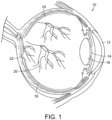
- FIG. 1 a diagrammatic view of an eye, generally referred to by the reference number 10, is shown.
- the laser light is passed through the patient's cornea 12, pupil 14, and lens 16 and directed onto the retina 18.
- the retina 18 is a thin tissue layer which captures light and transforms it into the electrical signals for the brain. It has many blood vessels, such as those referred to by reference number 20, to nourish it.
- Various retinal diseases and disorders, and particularly vascular retinal diseases such as diabetic retinopathy, are treated using conventional thermal retinal photocoagulation, as discussed above.
- the fovea/macula region referred to by the reference number 22 in FIG. 1 , is a portion of the eye used for color vision and fine detail vision.
- the fovea is at the center of the macula, where the concentration of the cells needed for central vision is the highest. Although it is this area where diseases such as age-related macular degeneration are so damaging, this is the area where conventional photocoagulation phototherapy cannot be used as damaging the cells in the foveal area can significantly damage the patient's vision. Thus, with current convention photocoagulation therapies, the foveal region is avoided.
- thermal tissue damage may be the sole source of the many potential complications of conventional photocoagulation which may lead to immediate and late visual loss.
- complications include inadvertent foveal burns, pre- and sub-retinal fibrosis, choroidal neovascularization, and progressive expansion of laser scars.
- Inflammation resulting from the tissue destruction may cause or exacerbate macular edema, induced precipitous contraction of fibrovascular proliferation with retinal detachment and vitreous hemorrhage, and cause uveitis, serous choroidal detachment, angle closure or hypotony.
- retinal photocoagulation treatment typically using a visible laser light
- retinal photocoagulation treatment is the current standard of care for proliferative diabetic retinopathy, as well as other retinopathy and retinal diseases, including diabetic macular edema and retinal venous occlusive diseases which also respond well to retinal photocoagulation treatment.
- retinal photocoagulation is the current standard of care for many retinal diseases, including diabetic retinopathy.
- Another problem is that the treatment requires the application of a large number of laser doses to the retina, which can be tedious and time-consuming.
- such treatments call for the application of each dose in the form of a laser beam spot applied to the target tissue for a predetermined amount of time, from a few hundred milliseconds to several seconds.
- the laser spots range from 50-500 microns in diameter. Their laser wavelength may be green, yellow, red or even infrared. It is not uncommon for hundreds or even in excess of one thousand laser spots to be necessary in order to fully treat the retina.
- the physician is responsible for insuring that each laser beam spot is properly positioned away from sensitive areas of the eye, such as the fovea, that could result in permanent damage. Laying down a uniform pattern is difficult and the pattern is typically more random than geometric in distribution. Point-by-point treatment of a large number of locations tends to be a lengthy procedure, which frequently results in physician fatigue and patient discomfort.
- U.S. Patent No. 6,066,128, to Bahmanyar describes a method of multi-spot laser application, in the form of retinal-destructive laser photocoagulation, achieved by means of distribution of laser irradiation through an array of multiple separate fiber optic channels and micro lenses. While overcoming the disadvantages of a point-by-point laser spot procedure, this method also has drawbacks.
- a limitation of the Bahmanyar method is differential degradation or breakage of the fiber optics or losses due to splitting the laser source into multiple fibers, which can lead to uneven, inefficient and/or suboptimal energy application.
- Another limitation is the constraint on the size and density of the individual laser spots inherent in the use of an optical system of light transmission fibers in micro lens systems. The mechanical constraint of dealing with fiber bundles can also lead to limitations and difficulties focusing and aiming the multi-spot array.
- U.S. Patent Publication 2010/0152716 A1 to Previn describes a different system to apply destructive laser irradiation to the retina using a large retinal laser spot with a speckle pattern, oscillated at a high frequency to homogenize the laser irradiance throughout the spot.
- a problem with this method is the uneven heat buildup, with higher tissue temperatures likely to occur toward the center of the large spot. This is aggravated by uneven heat dissipation by the ocular circulation resulting in more efficient cooling towards the margins of the large spot compared to the center. That is, the speckle pattern being oscillated at a high frequency can cause the laser spots to be overlapping or so close to one another that heat builds up and undesirable tissue damage occurs.
- Previn's speckle technique achieves averaging of point laser exposure within the larger exposure via the random fluctuations of the speckle pattern. However, such averaging results from some point exposures being more intense than others, whereas some areas within the exposure area may end with insufficient laser exposure, whereas other areas will receive excessive laser exposure. In fact, Previn specifically notes the risk of excessive exposure or exposure of sensitive areas, such as the fovea, which should be avoided with this system. Although these excessively exposed spots may result in retinal damage, Previn's invention is explicitly intended to apply damaging retinal photocoagulation to the retina, other than the sensitive area such as the fovea.
- CN 104 487 031 A to Luttrull describes a system and process for treating retinal diseases including passing a plurality of laser light beams through an optical lens or mask to optically shape the beams. The shaped beams are applied to at least a portion of the retina.
- Luttrull microshifting as claimed in the present application is not disclosed.
- subthreshold photocoagulation in which no visible tissue damage or laser lesions were detectable by any known means including ophthalmoscopy; infrared, color, red-free or autofluorescence fundus photography in standard or retro-mode; intravenous fundus fluorescein or indocyanine green angiographically, or Spectral-domain optical coherence tomography at the time of treatment or any time thereafter has produced similar beneficial results and treatment without many of the drawbacks and complications resulting from conventional visible threshold and suprathreshold photocoagulation treatments.
- subthreshold photocoagulation treatment can be, and may ideally be, applied to the entire retina, including sensitive areas such as the fovea, without visible tissue damage or the resulting drawbacks or complications of conventional visible retinal photocoagulation treatments.
- the treatment is not only harmless, it uniquely improves function of the retina and fovea in a wide variety of retinopathies immediately and is thus restorative to the retina.
- by desiring to treat the entire retina, or confluently treat portions of the retina laborious and time-consuming point-by-point laser spot therapy can be avoided.
- the inefficiencies and inaccuracies inherent to invisible endpoint laser treatment resulting in suboptimal tissue target coverage can also be avoided.
- Glaucoma is a group of eye diseases which result in damage to the optic nerve and vision loss.
- the most common type is open-angle glaucoma, which develops slowly over time and there is no pain. Side vision may begin to decrease followed by central vision, resulting in blindness if not treated. If treated early, however, it is possible to slow or stop the progression of the disease.
- the underlying cause of open-angle glaucoma remains unclear, however, the major risk factor for most glaucoma and the focus of treatment is increased intraocular pressure (IOP). The goal of these treatments is to decrease eye pressure.
- IOP intraocular pressure
- OAG open-angle glaucoma
- a system and method for providing a therapy which provides neuroprotection to the optic nerve so as to improve the optic nerve function or condition There is also a continuing need for such a method and system which can be administered to the retina which does not create detectible retinal burns or lesions and thus does not permanently damage or destroy the retinal tissue, while improving the function and health of the retinal ganglion cells and/or the optic nerve.
- Such a system and method should be able to be applied to the entire retina, including sensitive areas such as the fovea, without visible tissue damage or the resulting drawbacks or complications of conventional visible retinal photocoagulation treatments.
- the present invention fulfills these needs and provides other related advantages.
- the present invention is set out in claim 1.
- the embodiments, aspects or examples according to the present description which do not fall within the scope of said claims are provided for illustrative purposes only and do not form part of the present invention.
- the present disclosure resides in a process and system for treating retinal diseases and disorders and providing neuroprotective treatment in glaucoma by means of harmless, restorative subthreshold photocoagulation phototherapy.
- a laser light beam having predetermined operating parameters and characteristics is applied to the retinal and/or foveal tissue of an eye having glaucoma or a risk of glaucoma to create a therapeutic effect to the retinal and/or foveal tissue exposed to the laser light beam without destroying or permanently damaging the retinal and/or foveal tissue, while improving the function or condition of an optic nerve or retinal ganglion cells of the eye.
- a system for providing glaucoma neuroprotective treatment comprises a laser console generating a micropulsed laser light beam.
- the laser light beam is passed through an optical lens or mask to optically shape the laser light beam.
- a coaxial wide-field non-contact digital optical viewing camera projects the laser light beam to an area of a desired site of a retina and/or fovea of an eye for performing retinal phototherapy or photostimulation.
- An optical scanning mechanism controllably directs the light beam onto the retina and/or fovea to provide a therapeutic effect to the retinal and/or foveal tissue and improve optical nerve or retinal ganglion cell function or condition.
- the laser light beam has characteristics of providing a therapeutic effect to retinal and/or foveal tissue without destroying or permanently damaging the retinal or foveal tissue.
- the laser light beam typically has a wavelength greater than 532 nm.
- the laser light radiant beam may have an infrared wavelength such as between 750 nm - 1300 nm, and preferably approximately 810 nm.
- the laser has a duty cycle of less than 10%, and preferably a duty cycle of 5% or less.
- the exposure envelope of the laser is generally 500 milliseconds or less, and the micropulse frequency is preferably 500 Hz.
- the light beam may have an intensity between 100-590 watts per square centimeter, and preferably approximately 350 watts per square centimeter.
- the laser console may generate a plurality of micropulsed light beams, at least a plurality of the light beams having different wavelengths.
- the optical lens or mask may optically shape the light beam from the laser console into a geometric object or pattern. This may be done by diffractive optics to simultaneously generate a plurality of therapeutic beams or spots from the laser light beam, wherein the plurality of spots are projected from the coaxial wide-field non-contact digital optical viewing camera to at least a portion of the desired treatment area of the retina and/or fovea.
- the laser light beam is controllably moved, such as using an optical scanning mechanism, to achieve complete coverage of the desired site for performing retinal phototherapy or photostimulation.
- the optical scanning mechanism may controllably move the light beam until substantially all of the retina and fovea have been exposed to the light beam.
- the laser light beam may be selectively applied to disease markers on the desired site for performing retinal phototherapy or photostimulation.
- the laser light beam may be projected to at least a portion of the center of the desired site for performing retinal phototherapy or photostimulation.
- a fundus image of the desired site for performing retinal phototherapy or photostimulation may be displayed parallel to or super imposed over a result image from a retinal diagnostic modality.
- the laser light beam or geometric object or pattern is controllably moved by the optical scanning mechanism to different treatment areas between micropulses of the laser light beam.
- the laser light beam is controllably returned to the previously treated or exposed area within less than a second from the previous application of the laser light to the area. More typically, the laser light beam is returned to the previously treated or exposed area within one millisecond to three milliseconds.
- a process for performing retinal phototherapy or photostimulation comprises the step of generating a laser light beam that creates a therapeutic effect to retinal and/or foveal tissue exposed to the laser light without destroying or permanently damaging the retinal or foveal tissue.
- Parameters of the generated laser light beam including the pulse length, power, and duty cycle are selected to create a therapeutic effect with no visible laser lesions or tissue damage detected ophthalmoscopically or angiographically or to any currently known means after treatment.
- the laser light beam has a wavelength greater than 532 nm and a duty cycle of less than 10%.
- the laser light beam may have a wavelength of between 750 nm and 1300 nm.
- the laser light beam may have a duty cycle of approximately 5% or less.
- the laser light beam may have an intensity of 100-590 watts per square centimeter, and a pulse length of 500 milliseconds or less.
- the laser light beam is applied to the retinal and/or foveal tissue of an eye having glaucoma or risk of glaucoma to create a therapeutic effect to the retinal and/or foveal tissue exposed to the laser light beam without destroying or permanently damaging the retinal and/or foveal tissue and improve function or condition of an optic nerve or retinal ganglion cells of the eye.
- the laser light beam may be applied to both retinal and foveal tissue of the eye, and the entire retina, including the fovea, may be treated without damaging retinal or foveal tissue while still providing the benefits of the present invention.
- a plurality of laser light beams from a plurality of micropulsed lasers having different wavelengths may be applied onto the retinal and/or foveal tissue of the eye.
- a plurality of spaced apart treatment laser spots may be formed and simultaneously applied to the retinal and/or foveal tissue of the eye.
- a plurality of laser light spots may be controllably moved to treat adjacent retinal tissue.
- a single micropulse of laser light is less than a millisecond in duration, and may be between 50 microseconds to 100 microseconds in duration.
- the laser light spots are reapplied to a first treatment area of the retina and/or fovea.
- the laser light is applied to at least one other area of the retina and/or fovea to be treated that is spaced apart from the first treatment area.
- the adjacent areas are separated by at least a predetermined minimum distance to avoid thermal tissue damage.
- the interval of time between laser light applications to a treatment area is less than one second, and more typically between one and three milliseconds.
- the laser light spots are repeatedly applied to each of the areas to be treated until a predetermined number of laser light applications to each area to be treated has been achieved.
- the predetermined number of laser light applications to each treatment area may be between 50 to 200, and more typically 75 to 150.
- the laser light is reapplied to previously treated areas in sequence.
- the present disclosure relates to a system and process for treating glaucoma. More particularly, the present disclosure relates to a system and process for providing neuroprotective therapy for glaucoma by means of predetermined parameters producing harmless, yet therapeutic, true subthreshold photocoagulation.
- retinal laser treatment that does not cause any laser-induced retinal damage, but can be at least as effective as conventional retinal photocoagulation is contrary to conventional thinking and practice.
- Conventional thinking assumes that the physician must intentionally create retinal damage as a prerequisite to therapeutically effective treatment.
- FIGS. 2A-2D are graphic representations of the effective surface area of various modes of retinal laser treatment for retinal vascular disease.
- the gray background represents the retina 18 which is unaffected by the laser treatment.
- the black areas 24 are areas of the retina which are destroyed by conventional laser techniques.
- the lighter gray or white areas 26 represent the areas of the retina secondarily affected by the laser, but not destroyed.
- FIG. 2A illustrates the therapeutic effect of conventional argon laser retinal photocoagulation.
- the therapeutic effects attributed to laser-induced thermal retinal destruction include reduced metabolic demand, debulking of diseased retina, increased intraocular oxygen tension and ultra production of vasoactive cytokines, including vascular endothelial growth factor (VEGF).
- VEGF vascular endothelial growth factor
- RPE retinal pigment epithelium
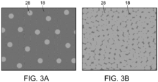
- FIG. 3A represents the use of a low-intensity and low-density laser, such as a micropulsed diode laser in accordance with the invention, sometimes referred to herein as subthreshold diode micropulse laser treatment (SDM).
- SDM subthreshold diode micropulse laser treatment
- the subthreshold retinal photocoagulation sometimes referred to as "true subthreshold”, of the invention is defined as retinal laser applications biomicroscopically invisible at the time of treatment.
- the term “subthreshold” has often been used in the art to describe several different clinical scenarios reflecting widely varying degrees of laser-induced thermal retinal damage.
- the use of the term “subthreshold” falls into three categories reflecting common usage and the historical and morphological evolution of reduced-intensity photocoagulation for retinal vascular disease toward truly invisible phototherapy or true subthreshold photocoagulation which the invention embodies.
- “Classical subthreshold” for photocoagulation describes the early attempts at laser intensity reduction using conventional continuous argon, krypton, and diode lasers. Although the retinal burns were notably less obvious than the conventional "threshold” (photocoagulation confined to the outer retina and thus less visible at time of treatment) or even milder “suprathreshold” (full-thickness retinal photocoagulation generally easily visible at the time of treatment), the lesions of "classical” subthreshold photocoagulation were uniformly visible both clinically and by fundus fluorescein angiography (FFA) at the time of treatment and thereafter.
- FFA fundus fluorescein angiography
- “Clinical subthreshold” photocoagulation describes the next epiphany of evolution of laser-induced retinal damage reduction, describing a lower-intensity but persistently damaging retinal photocoagulation using either a micropulsed laser or short-pulsed continuous wave laser that better confine the damage to the outer retina and retinal pigmentation epithelium.
- the laser lesions may in fact be ophthalmoscopically invisible at the time of treatment, however, as laser-induced retinal damage remains the intended point of treatment, laser lesions are produced which generally become increasingly clinically visible with time, and many, if not all, laser lesions can be seen by FFA, fundus autofluorescence photography (FAF), and/or spectral-domain (SD) optical coherence tomography (OCT) at the time of treatment and thereafter.
- FFA fundus autofluorescence photography
- SD spectral-domain optical coherence tomography
- “True” subthreshold photocoagulation is invisible and includes laser treatment non-discernible by any other known means such as FFA, FAF, or even SD-OCT.
- "True subthreshold” photocoagulation is therefore defined as a laser treatment which produces absolutely no retinal damage detectable by any means at the time of treatment or any time thereafter by known means of detection.
- FIGS. 3A and 3B diagrammatically represent the result of "true", invisible subthreshold photocoagulation.
- the American Standards Institute has developed standards for safe workplace laser exposure based on the combination of theoretical and empirical data.
- the "maximum permissible exposure” (MPE) is the safety level, set at approximately 1/10 th of the laser exposure level expected to produce biological effects.
- MPE maximum permissible exposure
- absolute safety would be expected and retinal exposure to laser radiation at this level would be expected to have no biologic affect.
- a 50% of some risk of suffering a barely visible (threshold) retinal burn is generally encountered at 10 times MPE for conventional continuous wave laser exposure.
- the risk of threshold retinal burn is approximately 100 times MPE.
- the therapeutic range - the interval of doing nothing at all and the 50% of some likelihood of producing a threshold retinal burn - for low-duty cycle micropulsed laser irradiation is 10 times wider than for continuous wave laser irradiation with the same energy. It has been determined that safe and effective subthreshold photocoagulation using a low-duty cycle micropulsed diode laser is between 18 times and 55 times MPE, such as with a preferred laser exposure to the retina at 47 times MPE for a near-infrared 810 nm diode laser. At this level, the inventor has observed that there is therapeutic effectiveness with no retinal damage whatsoever.
- the intensity or power of a low-duty cycle 810nm laser beam between 100 watts to 590 watts per square centimeter is effective yet safe.
- a particularly preferred intensity or power of the laser light beam is approximately 250-350 watts per square centimeter for an 810nm micropulsed diode laser.
- the radiant beam of an 810nm diode laser should have an exposure envelope duration of 500 milliseconds or less, and preferably approximately 100-300 milliseconds.
- the exposure duration will be lessened accordingly.
- the exposure envelope duration is a duration of time where the micropulsed laser beam would be exposed to the same spot or location of the retina, although the actual time of exposure of the tissue to the laser is much less as the laser light pulse is less than a millisecond in duration, and typically between 50 microseconds to 100 microseconds in duration.
- Invisible phototherapy or true subthreshold photocoagulation in accordance with the present invention can be performed at various laser light wavelengths, such as from a range of 532 nm to 1300 nm. Use of a different wavelength can impact the preferred intensity or power of the laser light beam and the exposure envelope duration in order that the retinal tissue is not damaged, yet therapeutic effect is achieved.
- duty cycle the frequency of the train of micropulses, or the length of the thermal relaxation time in between consecutive pulses. It has been found that the use of a 10% duty cycle or higher adjusted to deliver micropulsed laser at similar irradiance at similar MPE levels significantly increase the risk of lethal cell injury, particularly in darker fundi. However, duty cycles less than 10%, and preferably approximately 5% duty cycle or less have demonstrated adequate thermal rise and treatment at the level of the RPE cell to stimulate a biologic response, but remained below the level expected to produce lethal cell injury, even in darkly pigmented fundi. Moreover, if the duty cycle is less than 5%, the exposure envelope duration in some instances can exceed 500 milliseconds.
- the use of small retinal laser spots is used. This is due to the fact that larger spots can contribute to uneven heat distribution and insufficient heat dissipation within the large retinal laser spot, potentially causing tissue damage or even tissue destruction towards the center of the larger laser spot.
- "small” would generally apply to retinal spots less than 3mm in diameter.
- the smaller the retinal spot the more ideal the heat dissipation and uniform energy application becomes.
- small spots such as 25-300 micrometers in diameter, or small geometric lines or other objects are preferred so as to maximize even heat distribution and heat dissipation to avoid tissue damage.
- "true" subthreshold photocoagulation phototherapy in accordance with the present invention enables the physician to apply a "low-intensity/high-density" phototherapy treatment, such as illustrated in FIG. 3B , and treat the entire retina, including sensitive areas such as the macula and even the fovea without creating visual loss or other damage.
- a "low-intensity/high-density” phototherapy treatment such as illustrated in FIG. 3B
- the entire retina, and particularly the fovea cannot be treated as it will create vision loss due to the tissue damage in sensitive areas.
- the present invention spares the neurosensory retina and is selectively absorbed by the RPE.
- Current theories of the pathogenesis of retinal vascular disease especially implicate cytokines, potent extra cellular vasoactive factors produced by the RPE, as important mediators of retinal vascular disease.
- the present invention both selectively targets and avoids lethal buildup within RPE.
- the capacity for the treated RPE to participate in a therapeutic response is preserved and even enhanced rather than eliminated as a result their destruction of the RPE in conventional photocoagulation therapies.
- cytokines may follow a "U-shaped curve" where small physiologic changes in cytokine production, denoted by the left side of curve, may have large clinical effects comparable to high-dose (pharmacologic) therapy (denoted by the right side of the curve).
- Using sublethal laser exposures in accordance with the present invention may be working on the left side of the curve where the treatment response may approximate more of an "on/off" phenomenon rather than a dose-response. This might explain the clinical effectiveness of the present invention observed at low reported irradiances. This is also consistent with clinical experience and in-vitro studies of laser-tissue interaction, wherein increasing irradiance may simply increase the risk of thermal retinal damage without improving the therapeutic effect.
- HSPs heat shock proteins
- SDM produces photothermal, rather than photochemical, cellular stress.
- SDM is able to affect the tissue, including RPE, without damaging it.
- SDM produces prompt clinical effects, such as rapid and significant improvement in retinal electrophysiology, visual acuity, contrast visual acuity and improved macular sensitivity measured by microperimetry, as well as long-term effects, such as reduction of DME and involution of retinal neovascularization.
- the invisible, true subthreshold photocoagulation phototherapy maximizes the therapeutic recruitment of the RPE through the concept of "maximize the affected surface area", in that all areas of RPE exposed to the laser irradiation are preserved, and available to contribute therapeutically.
- conventional therapy creates a therapeutic ring around the burned or damaged tissue areas, whereas the present invention creates a therapeutic area without any burned or otherwise destroyed tissue.
- FIG. 4 spectral-domain OCT imaging is shown in FIG. 4 of the macular and foveal area of the retina before treatment with the present invention.
- FIG. 5 is of the optical coherence tomography (OCT) image of the same macula and fovea after treatment using the present invention, using a 131 micrometer retinal spot, 5% duty cycle, 0.3 second pulse duration, 0.9 watt peak power placed throughout the area of macular thickening, including the fovea.
- OCT optical coherence tomography
- a low red to infrared laser light beam such as from an 810nm micropulsed diode laser
- an argon laser is used instead of an argon laser.
- the 810 nm diode laser is minimally absorbed and negligibly scattered by intraretinal blood, cataract, vitreous hemorrhage and even severely edematous neurosensory retina. Differences in fundus coloration result primarily from differences in choroid pigmentation, and less of variation of the target RPE. Treatment in accordance with the present invention is thus simplified, requiring no adjustment in laser parameters for variations in macular thickening, intraretinal hemorrhage, and media opacity such as cataracts or fundus pigmentation, reducing the risk of error.
- the present invention could be utilized with micropulsed emissions of other wavelengths, such as the recently available 577 nm yellow and 532 nm green lasers, and others.
- the higher energies and different tissue absorption characteristic of shorter wavelength lasers may increase retinal burn risk, effectively narrowing the therapeutic window.
- the shorter wavelengths are more scattered by opaque ocular media, retinal hemorrhage and macular edema, potentially limiting usefulness and increasing the risk of retinal damage in certain clinical settings.
- a low red to infrared laser light beam is still preferred.
- low power red and near-infrared laser exposure is known to positively affect many cell types, particularly normalizing the behavior of cells and pathological environments, such as diabetes, through a variety of intracellular photo-acceptors.
- Cell function, in cytokine expression is normalized and inflammation reduced.
- the invention may induce changes in the expression of multiple factors physiologically as opposed to drug therapy that typically narrowly targets only a few post-cellular factors pharmacologically.
- the laser-induced physiologic alteration of RPE cytokine expression may account for the slower onset but long lasting benefits using the present invention.
- a physiologically invisible infrared or near-infrared laser wavelength such as 750 nm - 1300 nm
- 750 nm - 1300 nm is perceived as comfortable by the patient, and does not cause reactive pupillary constriction, allowing visualization of the ocular fundus and treatment of the retina to be performed without pharmacologic dilation of the patient pupil.
- This also eliminates the temporary of visual disability typically lasting many hours following pharmacologic pupillary dilation currently required for treatment with conventional laser photocoagulation.
- patient eye movement is a concern not only for creating the pattern of laser spots to treat the intended area, but also could result in exposure of conventional therapy to sensitive areas of the eye, such as the fovea, resulting in loss of vision or other complications.
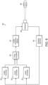
- the system includes a laser console 32, such as for example the 810 nm near infrared micropulsed diode laser in the preferred embodiment.
- the laser generates a laser light beam which is passed through optics, such as an optical lens or mask, or a plurality of optical lenses and/or masks 34 as needed.
- the laser projector optics 34 pass the shaped light beam to a coaxial wide-field non-contact digital optical viewing system/camera 36 for projecting the laser beam light onto the eye 38 of the patient.
- box labeled 36 can represent both the laser beam projector as well as a viewing system/camera, which might in reality comprise two different components in use.
- the viewing system/camera 36 provides feedback to a display monitor 40, which may also include the necessary computerized hardware, data input and controls, etc. for manipulating the laser 32, the optics 34, and/or the projection/viewing components 36.
- the laser light beam 42 is passed through a collimator lens 44 and then through a mask 46.
- the mask 46 comprises a diffraction grating.
- the mask/diffraction grating 46 produces a geometric object, or more typically a geometric pattern of simultaneously produced multiple laser spots or other geometric objects. This is represented by the multiple laser light beams labeled with reference number 48.
- the multiple laser spots may be generated by a plurality of fiber optic wires. Either method of generating laser spots allows for the creation of a very large number of laser spots simultaneously over a very wide treatment field, such as consisting of the entire retina.
- a very high number of laser spots perhaps numbering in the hundreds even thousands or more could cover the entire ocular fundus and entire retina, including the macula and fovea, retinal blood vessels and optic nerve.
- the intent of the process in the present invention is to better ensure complete and total coverage and treatment, sparing none of the retina by the laser so as to improve vision.
- optical features with a feature size on par with the wavelength of the laser employed, for example using a diffraction grating it is possible to take advantage of quantum mechanical effects which permits simultaneous application of a very large number of laser spots for a very large target area.
- the individual spots produced by such diffraction gratings are all of a similar optical geometry to the input beam, with minimal power variation for each spot.
- the result is a plurality of laser spots with adequate irradiance to produce harmless yet effective treatment application, simultaneously over a large target area.
- the present invention also contemplates the use of other geometric objects and patterns generated by other diffractive optical elements.
- the laser light passing through the mask 46 diffracts, producing a periodic pattern a distance away from the mask 46, shown by the laser beams labeled 48 in FIG. 7 .
- the single laser beam 42 has thus been formed into multiple, up to hundreds or even thousands, of individual laser beams 48 so as to create the desired pattern of spots or other geometric objects.
- These laser beams 48 may be passed through additional lenses, collimators, etc. 50 and 52 in order to convey the laser beams and form the desired pattern on the patient's retina. Such additional lenses, collimators, etc. 50 and 52 can further transform and redirect the laser beams 48 as needed.
- Arbitrary patterns can be constructed by controlling the shape, spacing and pattern of the optical mask 46.
- the pattern and exposure spots can be created and modified arbitrarily as desired according to application requirements by experts in the field of optical engineering.
- Photolithographic techniques especially those developed in the field of semiconductor manufacturing, can be used to create the simultaneous geometric pattern of spots or other objects.
- the number of simultaneous spots generated and used could number from as few as 1 and up to approximately 100 when a 0.04 (4%) duty cycle and a total train duration of 0.3 seconds (300 milliseconds) is used for panretinal coverage.
- the water absorption increases as the wavelength is increased, resulting in heating over the long path length through the vitreous humor in front of the retina.
- the absorption coefficient in the RPE's melanin can be higher, and therefore the laser power can be lower.
- the power can be lowered by a factor of 4 for the invention to be effective. Accordingly, there can be as few as a single laser spot or up to approximately 400 laser spots when using the 577 nm wavelength laser light, while still not harming or damaging the eye.
- the present invention can use a multitude of simultaneously generated therapeutic light beams or spots, such as numbering in the dozens or even hundreds, as the parameters and methodology of the present invention create therapeutically effective yet non-destructive and non-permanently damaging treatment, allowing the laser light spots to be applied to any portion of the retina, including the fovea, whereas conventional techniques are not able to use a large number of simultaneous laser spots, and are often restricted to only one treatment laser beam, in order to avoid accidental exposure of sensitive areas of the retina, such as the fovea, as these will be damaged from the exposure to conventional laser beam methodologies, which could cause loss of eyesight and other complications.
- FIG. 8 illustrates diagrammatically a system which couples multiple light sources into the pattern-generating optical subassembly described above.
- this system 30' is similar to the system 30 described in FIG. 6 above.
- the primary differences between the alternate system 30' and the earlier described system 30 is the inclusion of a plurality of laser consoles 32, the outputs of which are each fed into a fiber coupler 54.
- the fiber coupler produces a single output that is passed into the laser projector optics 34 as described in the earlier system.
- the coupling of the plurality of laser consoles 32 into a single optical fiber is achieved with a fiber coupler 54 as is known in the art.
- Other known mechanisms for combining multiple light sources are available and may be used to replace the fiber coupler described herein.
- the multiple light sources 32 follow a similar path as described in the earlier system 30, i.e., collimated, diffracted, recollimated, and directed into the retina with a steering mechanism.
- the diffractive element must function differently than described earlier depending upon the wavelength of light passing through, which results in a slightly varying pattern. The variation is linear with the wavelength of the light source being diffracted.
- the difference in the diffraction angles is small enough that the different, overlapping patterns may be directed along the same optical path through the steering mechanism 36 to the retina 38 for treatment. The slight difference in the diffraction angles will affect how the steering pattern achieves coverage of the retina.
- This sequential offsetting can be accomplished in two modes. In the first mode, all wavelengths of light are applied simultaneously without identical coverage. An offsetting steering pattern to achieve complete coverage for one of the multiple wavelengths is used. Thus, while the light of the selected wavelength achieves complete coverage of the retina, the application of the other wavelengths achieves either incomplete or overlapping coverage of the retina.
- the second mode sequentially applies each light source of a varying or different wavelength with the proper steering pattern to achieve complete coverage of the retina for that particular wavelength. This mode excludes the possibility of simultaneous treatment using multiple wavelengths, but allows the optical method to achieve identical coverage for each wavelength. This avoids either incomplete or overlapping coverage for any of the optical wavelengths.
- These modes may also be mixed and matched.
- two wavelengths may be applied simultaneously with one wavelength achieving complete coverage and the other achieving incomplete or overlapping coverage, followed by a third wavelength applied sequentially and achieving complete coverage.
- FIG. 9 illustrates diagrammatically yet another alternate embodiment of the inventive system 30".
- This system 30" is configured generally the same as the system 30 depicted in FIG. 6 .
- the main difference resides in the inclusion of multiple pattern-generating subassembly channels tuned to a specific wavelength of the light source.
- Multiple laser consoles 32 are arranged in parallel with each one leading directly into its own laser projector optics 34.
- the laser projector optics of each channel 58a, 58b, 58c comprise a collimator 44, mask or diffraction grating 48 and recollimators 50, 52 as described in connection with FIG. 7 above - the entire set of optics tuned for the specific wavelength generated by the corresponding laser console 32.
- the output from each set of optics 34 is then directed to a beam splitter 56 for combination with the other wavelengths. It is known by those skilled in the art that a beam splitter used in reverse can be used to combine multiple beams of light into a single output.
- the combined channel output from the final beam splitter 56c is then directed through the camera 36 which applies a steering mechanism to allow for complete coverage of the retina 38.
- the optical elements for each channel are tuned to produce the exact specified pattern for that channel's wavelength. Consequently, when all channels are combined and properly aligned a single steering pattern may be used to achieve complete coverage of the retina for all wavelengths.
- the system 30" may use as many channels 58a, 58b, 58c, etc. and beam splitters 56a, 56b, 56c, etc. as there are wavelengths of light being used in the treatment.
- Implementation of the system 30" may take advantage of different symmetries to reduce the number of alignment constraints.
- the proposed grid patterns are periodic in two dimensions and steered in two dimensions to achieve complete coverage.
- the patterns for each channel are identical as specified, the actual pattern of each channel would not need to be aligned for the same steering pattern to achieve complete coverage for all wavelengths.
- Each channel would only need to be aligned optically to achieve an efficient combination.
- each channel begins with a light source 32, which could be from an optical fiber as in other embodiments of the pattern-generating subassembly.
- This light source 32 is directed to the optical assembly 34 for collimation, diffraction, recollimation and directed into the beam splitter which combines the channel with the main output.
- the field of photobiology reveals that different biologic effects may be achieved by exposing target tissues to lasers of different wavelengths. The same may also be achieved by consecutively applying multiple lasers of either different or the same wavelength in sequence with variable time periods of separation and/or with different irradiant energies.
- the present invention anticipates the use of multiple laser, light or radiant wavelengths (or modes) applied simultaneously or in sequence to maximize or customize the desired treatment effects. This method also minimizes potential detrimental effects.
- the optical methods and systems illustrated and described above provide simultaneous or sequential application of multiple wavelengths.
- the system of the present invention incorporates a guidance system to ensure complete and total retinal treatment with retinal photostimulation.
- This guidance system is to be distinguished from traditional retinal laser guidance systems that are employed to both direct treatment to a specific retinal location; and to direct treatment away from sensitive locations such as the fovea that would be damaged by conventional laser treatment, as the treatment method of the present invention is harmless, the entire retina, including the fovea and even optical nerve, can be treated.
- protection against accidental visual loss by accidental patient movement is not a concern. Instead, patient movement would mainly affect the guidance in tracking of the application of the laser light to ensure adequate coverage.
- Fixation/tracking/registration systems consisting of a fixation target, tracking mechanism, and linked to system operation are common in many ophthalmic diagnostic systems and can be incorporated into the present invention.
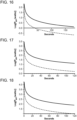
- the geometric pattern of simultaneous laser spots is sequentially offset so as to achieve confluent and complete treatment of the retinal surface.
- a segment of the retina can be treated in accordance with the present invention, more ideally the entire retina will be treated within one treatment session. This is done in a time-saving manner by placing a plurality of spots over the entire ocular fundus at once. This pattern of simultaneous spots is scanned, shifted, or redirected as an entire array sequentially, so as to cover the entire retina in a single treatment session.
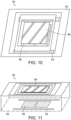
- FIGS. 10 and 11 illustrate an optical scanning mechanism 60 which may be used in the form of a MEMS mirror, having a base 62 with electronically actuated controllers 64 and 66 which serve to tilt and pan the mirror 68 as electricity is applied and removed thereto. Applying electricity to the controller 64 and 66 causes the mirror 68 to move, and thus the simultaneous pattern of laser spots or other geometric objects reflected thereon to move accordingly on the retina of the patient. This can be done, for example, in an automated fashion using an electronic software program to adjust the optical scanning mechanism 60 until complete coverage of the retina, or at least the portion of the retina desired to be treated, is exposed to the phototherapy.
- the optical scanning mechanism may also be a small beam diameter scanning galvo mirror system, or similar system, such as that distributed by Thorlabs. Such a system is capable of scanning the lasers in the desired offsetting pattern.
- the geometric pattern of laser spots can be overlapped without destroying the tissue or creating any permanent damage.
- the pattern of spots are offset at each exposure so as to create space between the immediately previous exposure to allow heat dissipation and prevent the possibility of heat damage or tissue destruction.
- the pattern illustrated for exemplary purposes as a grid of sixteen spots, is offset each exposure such that the laser spots occupy a different space than previous exposures.
- a 3mm x 3mm area which is useful for treatments, would require 98 offsetting operations, requiring a treatment time of approximately thirty seconds.
- Another example would be a 3 cm x 3 cm area, representing the entire human retinal surface.
- a much larger secondary mask size of 25mm by 25mm could be used, yielding a treatment grid of 190 spots per side separated by 133 ⁇ m with a spot size radius of 6 ⁇ m. Since the secondary mask size was increased by the same factor as the desired treatment area, the number of offsetting operations of approximately 98, and thus treatment time of approximately thirty seconds, is constant.
- Treatment times represent at least ten to thirty times reduction in treatment times compared to current methods of sequential individual laser spot applications.
- Field sizes of 3mm would, for example, allow treatment of the entire human macula in a single exposure, useful for treatment of common blinding conditions such as diabetic macular edema and age-related macular degeneration. Performing the entire 98 sequential offsettings would ensure entire coverage of the macula.
- the number and size of retinal spots produced in a simultaneous pattern array can be easily and highly varied such that the number of sequential offsetting operations required to complete treatment can be easily adjusted depending on the therapeutic requirements of the given application.
- quantum mechanical behavior may be observed which allows for arbitrary distribution of the laser input energy.
- Time savings from the use of simultaneous projection of geometric shapes or patterns permits the treatment fields of novel size, such as the 1.2 cm ⁇ 2 area to accomplish whole-retinal treatment, in a single clinical setting or treatment session.
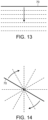
- a single line 70 of laser light formed by the continuously or by means of a series of closely spaced spots, can be created.
- An offsetting optical scanning mechanism can be used to sequentially scan the line over an area, illustrated by the downward arrow in FIG. 13 .
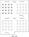
- the same geometric object of a line 70 can be rotated, as illustrated by the arrows, so as to create a circular field of phototherapy.
- the potential negative of this approach is that the central area will be repeatedly exposed, and could reach unacceptable temperatures. This could be overcome, however, by increasing the time between exposures, or creating a gap in the line such that the central area is not exposed.
- the micropulsed laser light beam of an 810 nm diode laser should have an exposure envelope duration of 500 milliseconds or less, and preferably approximately 300 milliseconds.
- the exposure duration should be lessened accordingly.
- duty cycle or the frequency of the train of micropulses, or the length of the thermal relaxation time between consecutive pulses. It has been found that the use of a 10% duty cycle or higher adjusted to deliver micropulsed laser at similar irradiance at similar MPE levels significantly increase the risk of lethal cell injury, particularly in darker fundi. However, duty cycles of less than 10%, and preferably 5% or less demonstrate adequate thermal rise and treatment at the level of the MPE cell to stimulate a biological response, but remain below the level expected to produce lethal cell injury, even in darkly pigmented fundi. The lower the duty cycle, however, the exposure envelope duration increases, and in some instances can exceed 500 milliseconds.
- Each micropulse lasts a fraction of a millisecond, typically between 50 microseconds to 100 microseconds in duration. Thus, for the exposure envelope duration of 300-500 milliseconds, and at a duty cycle of less than 5%, there is a significant amount of wasted time between micropulses to allow the thermal relaxation time between consecutive pulses. Typically, a delay of between 1 and 3 milliseconds, and preferably approximately 2 milliseconds, of thermal relaxation time is needed between consecutive pulses.
- the retinal cells are typically exposed or hit by the laser light between 50-200 times, and preferably between 75-150 at each location.
- the total time in accordance with the embodiments described above to treat a given area, or more particularly the locations on the retina which are being exposed to the laser spots is between 200 milliseconds and 500 milliseconds on average.
- the thermal relaxation time is required so as not to overheat the cells within that location or spot and so as to prevent the cells from being damaged or destroyed. While time periods of 200-500 milliseconds do not seem long, given the small size of the laser spots and the need to treat a relatively large area of the retina, treating the entire macula or the entire retina can take a significant amount of time, particularly from the perspective of a patient who is undergoing treatment.
- the present invention in a particularly preferred embodiment utilizes the interval between consecutive laser light applications to the same location (typically between 1 to 3 milliseconds) to apply the laser light to a second treatment area, or additional areas, of the retina and/or fovea that is spaced apart from the first treatment area.
- the laser beams are returned to the first treatment location, or previous treatment locations, within the predetermined interval of time so as to provide sufficient thermal relaxation time between consecutive pulses, yet also sufficiently treat the cells in those locations or areas properly by sufficiently increasing the temperature of those cells over time by repeatedly applying the laser light to that location in order to achieve the desired therapeutic benefits of the invention.
- approximately four additional areas which are sufficiently spaced apart from one another can be treated during the thermal relaxation intervals beginning with a first treatment area.
- multiple areas can be treated, at least partially, during the 200-500 millisecond exposure envelope for the first area.
- approximately 500 light spots can be applied during that interval of time in different treatment areas. This would be the case, for example, for a laser light beam having a wavelength of 810 nm. For shorter wavelengths, such as 570 nm, even a greater number of individual locations can be exposed to the laser beams to create light spots.
- approximately 2,000 spots could be covered during the interval between micropulse treatments to a given area or location.
- each location has between 50-200, and more typically between 75-150, light applications applied thereto over the course of the exposure envelope duration (typically 200-500 milliseconds) to achieve the desired treatment.
- the laser light would be reapplied to previously treated areas in sequence during the relaxation time intervals for each area or location. This would occur repeatedly until a predetermined number of laser light applications to each area to be treated have been achieved.
- FIGS. 15A-15D This is diagrammatically illustrated in FIGS. 15A-15D .
- FIG. 15A illustrates with solid circles a first area having laser light applied thereto as a first application.
- the laser beams are offset or microshifted to a second exposure area, followed by a third exposure area and a fourth exposure area, as illustrated in FIG. 15B , until the locations in the first exposure area need to be retreated by having laser light applied thereto again within the thermal relaxation time interval.
- the locations within the first exposure area would then have laser light reapplied thereto, as illustrated in FIG. 15C . Secondary or subsequent exposures would occur in each exposure area, as illustrated in FIG.
- Adjacent exposure areas must be separated by at least a predetermined minimum distance to avoid thermal tissue damage. Such distance is at least 0.5 diameter away from the immediately preceding treated location or area, and more preferably between 1-2 diameters away. Such spacing relates to the actually treated locations in a previous exposure area. It is contemplated by the present invention that a relatively large area may actually include multiple exposure areas therein which are offset in a different manner than that illustrated in FIG. 15 .
- the exposure areas could comprise the thin lines illustrated in FIGS. 13 and 14 , which would be repeatedly exposed in sequence until all of the necessary areas were fully exposed and treated. In accordance with the present invention, this can comprise a limited area of the retina, the entire macula or panmacular treatment, or the entire retina, including the fovea.
- the time required to treat that area of the retina to be treated or the entire retina is significantly reduced, such as by a factor of 4 or 5 times, such that a single treatment session takes much less time for the medical provider and the patient need not be in discomfort for as long of a period of time.
- a graph is provided wherein the x-axis represents the Log of the average power in watts and the y-axis represents the treatment time, in seconds.
- the lower curve is for panmacular treatment and the upper curve is for panretinal treatment.
- the areas of each retinal spot are 100 microns, and the laser power for these 100 micron retinal spots is 0.74 watts.
- the panmacular area is 0.55 CM 2 , requiring 7,000 panmacular spots total, and the panretinal area is 3.30 CM 2 , requiring 42,000 laser spots for full coverage.
- Each RPE spot requires a minimum energy in order for its reset mechanism to be adequately activated, in accordance with the present invention, namely, 38.85 joules for panmacular and 233.1 joules for panretinal.
- the shorter the treatment time the larger the required average power.
- there is an upper limit on the allowable average power which limits how short the treatment time can be.
- FIGS. 17 and 18 show how the total power depends on treatment time. This is displayed in FIG. 17 for panmacular treatment, and in FIG. 18 for panretinal treatment.
- the upper, solid line or curve represents the embodiment where there are no microshifts taking advantage of the thermal relaxation time interval, such as described and illustrated in FIG. 12 , whereas the lower dashed line represents the situation for such microshifts, as described and illustrated in FIG. 15 .
- the peak total power is less with microshifts than without microshifts. This means that less power is required for a given treatment time using the microshifting embodiment of the present invention.
- the allowable peak power can be advantageously used, reducing the overall treatment time.
- a log power of 1.0 (10 watts) would require a total treatment time of 20 seconds using the microshifting embodiment of the present invention, as described herein. It would take more than 2 minutes of time without the microshifts, and instead leaving the micropulsed light beams in the same location or area during the entire treatment envelope duration. There is a minimum treatment time according to the wattage. However, this treatment time with microshifting is much less than without microshifting. As the laser power required is much less with the microshifting, it is possible to increase the power in some instances in order to reduce the treatment time for a given desired retinal treatment area.
- the product of the treatment time and the average power is fixed for a given treatment area in order to achieve the therapeutic treatment in accordance with the present invention.
- the parameters of the laser light are selected to be therapeutically effective yet not destructive or permanently damaging to the cells, no guidance or tracking beams are required, only the treatment beams as all areas of the retina, including the fovea, can be treated in accordance with the present invention.
- the entire retina, including the fovea is treated in accordance with the present invention, which is simply not possible using conventional techniques.
- a continuous wave laser could potentially be used instead of a micropulsed laser.
- the continuous wave laser there is concern of overheating as the laser is moved from location to location in that the laser does not stop and there could be heat leakage and overheating between treatment areas.
- it is theoretically possible to use a continuous wave laser in practice it is not ideal and the micropulsed laser is preferred.
- a simplified user interface is permitted. While the operating controls could be presented and function in many different ways, the system permits a very simplified user interface that might employ only two control functions. That is, an "activate” button, wherein a single depression of this button while in “standby” would actuate and initiate treatment. A depression of this button during treatment would allow for premature halting of the treatment, and a return to "standby” mode.
- the activity of the machine could be identified and displayed, such as by an LED adjacent to or within the button.
- a second controlled function could be a "field size” knob.
- a single depression of this button could program the unit to produce, for example, a 3mm focal or a "macular” field spot.
- a second depression of this knob could program the unit to produce a 6mm or "posterior pole” spot.
- a third depression of this knob could program the unit to produce a "pan retinal” or approximately 160°-220° panoramic retinal spot or coverage area. Manual turning of this knob could produce various spot field sizes therebetween. Within each field size, the density and intensity of treatment would be identical. Variation of the field size would be produced by optical or mechanical masking or apertures, such as the iris or LCD apertures described below.
- Fixation software could monitor the displayed image of the ocular fundus. Prior to initiating treatment of a fundus landmark, such as the optic nerve, or any part or feature of either eye of the patient (assuming orthophoria), could be marked by the operator on the display screen. Treatment could be initiated and the software would monitor the fundus image or any other image-registered to any part of either eye of the patient (assuming orthophoria) to ensure adequate fixation. A break in fixation would automatically interrupt treatment. A break in fixation could be detected optically; or by interruption of low energy infrared beams projected parallel to and at the outer margins of the treatment beam by the edge of the pupil. Treatment would automatically resume toward completion as soon as fixation was established.
- a fundus landmark such as the optic nerve, or any part or feature of either eye of the patient (assuming orthophoria)
- Treatment could be initiated and the software would monitor the fundus image or any other image-registered to any part of either eye of the patient (assuming orthophoria) to ensure adequate fixation.
- the unit At the conclusion of treatment, determined by completion of confluent delivery of the desired laser energy to the target, the unit would automatically terminate exposure and default to the "on” or “standby” mode. Due to unique properties of this treatment, fixation interruption would not cause harm or risk patient injury, but only prolong the treatment session.
- the laser could be projected via a wide field non-contact lens to the ocular fundus. Customized direction of the laser fields or particular target or area of the ocular fundus other than the central area could be accomplished by an operator joy stick or eccentric patient gaze.
- the laser delivery optics could be coupled coaxially to a wide field non-contact digital ocular fundus viewing system.
- the image of the ocular fundus produced could be displayed on a video monitor visible to the laser operator. Maintenance of a clear and focused image of the ocular fundus could be facilitated by a joy stick on the camera assembly manually directed by the operator. Alternatively, addition of a target registration and tracking system to the camera software would result in a completely automated treatment system.
- a fixation image could be coaxially displayed to the patient to facilitate ocular alignment. This image would change in shape and size, color, intensity, blink or oscillation rate or other regular or continuous modification during treatment to avoid photoreceptor exhaustion, patient fatigue and facilitate good fixation.
- results or images from other retinal diagnostic modalities might be displayed in parallel or by superimposition on the display image of the patient's fundus to guide, aid or otherwise facilitate the treatment.
- This parallel or superimposition of images can facilitate identification of disease, injury or scar tissue on the retina.
- the invention described herein is generally safe for panretinal and/or trans-foveal treatment.
- a user i.e., surgeon, preparing to limit treatment to a particular area of the retina where disease markers are located or to prevent treatment in a particular area with darker pigmentation, such as from scar tissue.
- the camera 36 may be fitted with an iris aperture 72 configured to selectively widen or narrow the opening through which the light is directed into the eye 38 of the patient.
- FIG. 19 illustrates an opening 74 on a camera 36 fitted with such an iris aperture 72.
- the iris aperture 72 may be replaced or supplemented by a liquid crystal display (LCD) 76.
- the LCD 76 acts as a dynamic aperture by allowing each pixel in the display to either transmit or block the light passing through it.
- Such an LCD 76 is depicted in FIG. 20 .
- any one of the inventive systems 30, 30', 30" includes a display on a user interface with a live image of the retina as seen through the camera 36.
- the user interface may include an overlay of this live image of the retina to select areas where the treatment light will be limited or excluded by the iris aperture 72 and/or the LCD 76.
- the user may draw an outline on the live image as on a touch screen and then select for either the inside or the outside of that outline to have limited or excluded coverage.
- the user would draw an outline around the scar tissue and then mark the interior of that outline for exclusion from the laser treatment.
- the control system and user interface would then send the proper control signal to the LCD 76 to block the projected treatment light through the pixels over the selected scar tissue.
- the LCD 76 provides an added benefit of being useful for attenuating regions of the projected pattern. This feature may be used to limit the peak power output of certain spots within the pattern. Limiting the peak power of certain spots in the pattern with the highest power output can be used to make the treatment power more uniform across the retina.
- surgeon may use the fundus monitor to outline an area of the retina to be treated or avoided; and the designated area then treated or avoided by software directing the treatment beams to treat or avoid said areas without need or use of an obstructing LCD 76 diaphragm.
- the inventors have found that treatment in accordance with the invention of patients suffering from age-related macular degeneration (AMD) can slow the progress or even stop the progression of AMD. Further evidence of this restorative treatment effect is the inventor's finding that treatment can uniquely reduce the risk of vision loss in AMD due to choroidal neovascularization by 80%. Most of the patients have seen significant improvement in dynamic functional logMAR visual acuity and contrast visual acuity after the treatment in accordance with the invention, with some experiencing better vision. It is believed that this works by targeting, preserving, and "normalizing" (moving toward normal) function of the retinal pigment epithelium (RPE).
- RPE retinal pigment epithelium
- Treatment in accordance with the invention has also been shown to stop or reverse the manifestations of the diabetic retinopathy disease state without treatment-associated damage or adverse effects, despite the persistence of systemic diabetes mellitus.
- Studies published by the inventor have shown that the restorative effect of treatment can uniquely reduce the risk of progression of diabetic retinopathy by 85%.
- the invention might work by inducing a return to more normal cell function and cytokine expression in diabetes-affected RPE cells, analogous to hitting the "reset" button of an electronic device to restore the factory default settings.
- SDM treatment may directly affect cytokine expression and heat shock protein (HSP) activation in the targeted tissue, particularly the retinal pigment epithelium (RPE) layer.
- HSP heat shock protein
- Panretinal and panmacular SDM has been noted by the inventors to reduce the rate of progression of many retinal diseases, including severe non-proliferative and proliferative diabetic retinopathy, AMD, DME, etc.
- the known therapeutic treatment benefits of individuals having these retinal diseases coupled with the absence of known adverse treatment effects, allows for consideration of early and preventative treatment, liberal application and retreatment as necessary.
- the reset theory also suggests that the invention may have application to many different types of RPE-mediated retinal disorders.
- panmacular treatment can significantly improve retinal function and health, retinal sensitivity, and dynamic logMAR visual acuity and contrast visual acuity in dry age-related macular degeneration, retinitis pigmentosa, cone-rod retinal degenerations, and Stargardt's disease where no other treatment has previously been found to do so.
- a patient and more particularly an eye of the patient, has a risk for a retinal disease. This may be before retinal imaging abnormalities are detectable. Such a determination may be accomplished by ascertaining if the patient is at risk for a chronic progressive retinopathy, including diabetes, a risk for age-related macular degeneration or retinitis pigmentosa. Alternatively, or additionally, results of a retinal examination or retinal test of the patient may be abnormal. A specific test, such as a retinal physiology test or a genetic test, may be conducted to establish that the patient has a risk for a retinal disease.
- a laser light beam that is sublethal and creates true subthreshold photocoagulation and retinal tissue, is generated and at least a portion of the retinal tissue is exposed to the generated laser light beam without damaging the exposed retinal or foveal tissue, so as to provide preventative and protective treatment of the retinal tissue of the eye.
- the treated retina may comprise the fovea, foveola, retinal pigment epithelium (RPE), choroid, choroidal neovascular membrane, subretinal fluid, macula, macular edema, parafovea, and/or perifovea.
- the laser light beam may be exposed to only a portion of the retina, or substantially the entire retina and fovea.
- the retina is periodically retreated. This may be done according to a set schedule or when it is determined that the retina of the patient is to be retreated, such as by periodically monitoring visual and/or retinal function or condition of the patient.
- the present invention is particularly suited for treatment of retinal diseases, such as diabetic retinopathy and macular edema, it has been found that it can be used for other diseases as well.
- the system and process of the present invention could target the trabecular mesh work as treatment for glaucoma, accomplished by another customized treatment field template.
- treatment of retinal tissue using SDM as explained above, in eyes with advanced open-angle glaucoma have shown improved key measures of optic nerve and ganglion cell function, indicating a significant neuroprotective effect of this treatment. Visual fields also improved, and there was no adverse treatment effects.
- SDM in accordance with the present invention, may aid in the clinical management of glaucoma by reducing the risk of visual loss, independent of intraocular pressure (IOP) lowering.
- IOP intraocular pressure
- SDM Low-intensity/high density subthreshold (sublethal) diode micropulse laser
- RPE retinal pigment epithelial
- Twenty-two patients were identified as eligible for the study, having glaucomatous optic nerve cupping and/or visual field loss prior to SDM treatment, in accordance with the present invention.
- the entire posterior retina, including the fovea, circumscribed by the major vascular arcades was "painted" with 1500-2000 confluent spot applications of laser light having parameters of 810 nm wavelength, 200 UM aerial spot size, 5% duty cycle, 1.4-watt power and 0.15 second duration.
- IOPs range 6-23 mm Hg (average 13) on 0-3 (average 1.3) topical medications. None of the patients use systemic glaucoma medication.
- Preoperative Snellen visual acuity (VA) range 20/15 to counting fingers with a median of 20/52.
- VEP was performed using an office-based commercially available system (Diopsys TM NOVA-TR, Diopsys, Inc., Pine Brook, New Jersey, USA) approved by the FDA for research and clinical use. Testing was performed according to manufacturer guidelines (www.diopsys.com). Gold active, ground, and reference electrodes (1cm cup) were used to record the VEP. Following skin cleaning and abrasion, conductive gel was used to adhere the electrodes to the scalp. All subjects were refracted prior to testing and corrected for the 1-meter testing distance with a trial frame.
- VEP amplitude, latency, and alpha-wave activity (8-13 Hz) from the primary visual cortex were measured using one Grass gold active-channel electrode, one reference electrode, and one ground electrode placed according to manufacturer recommendations following confirmation of adequate testing impedence.
- An elastic headband was used to maintain electrode position on the scalp. Subjects then placed their head in a chinrest/headrest and instructed to gaze at the center of the monitor at eye level and centered along the midline. The VEP measurements were recorded binocularly in a darkened room, undilated.
- PERG was performed using standard protocols of a commercially available system (Diopsys ® Nova-ERG, Diopsys Corp., Pine Brook, New Jersey) according to International Society for Clinical Electrophysiology of Vision guidelines. Both eyes were tested simultaneously and recorded individually, undilated, and refracted for the 60 cm testing distance. For all visual stimuli, a luminance pattern occupying a 25° visual field is presented with a luminance reversal rate of 15 Hz.
- the PERG "Concentric Ring” (CR) visual stimulus optimized for analyzing peripheral retinal sensitivity was employed, presenting with a circle of one luminance and an outer ring with the contrasting luminance.
- the concentric ring stimulus used two sub-classes of stimuli with an inner circle occupying a visual field of 16° and 24°, respectively.
- the concentric ring stimuli used a mean luminance of 117.6 cd/m 2 with a contrast of 100%.
- Magnetic D is the frequency response of the time-domain averaged signal in microvolts ( ⁇ V).
- Inner retinal and/or ganglion cell dysfunction cause signal latencies resulting in magnitude and phase variability that reduce MagD( ⁇ V) by phase cancelation.
- Magnitude ( ⁇ V) [Mag( ⁇ V)] measures the frequency response of the total signal in microvolts ( ⁇ V).
- Mag ( ⁇ V) reflects the signal strength and electrode impedance of the individual test sessions, as well as a gross measure of inner retina and ganglion function.
- the MagD( ⁇ V)/Mag( ⁇ V) ratio thus provides a measure of patient response normalized to that particular test's electrical quality and thus minimizes inter-test variability.
- MagD(uv) should roughly equal Mag(uv).
- MagD( ⁇ V)/Mag( ⁇ V) should roughly equal Mag(uv).
- Omnifield resolution perimetry (ORP) (Sinclair Technologies, Inc, Media, Pennsylvania) is a mesoptic threshold test of the central 20° diameter visual field, measuring logMAR visual acuity by the correct identification of Landolt "C" positioning at each intercept, rather than detection of a light source against a photopic background, as is accomplished with Humphrey field testing.
- the Omnifield is intended to mimic the mesoptic environments of real-life vision tasks.
- the Landolt C's are flashed on a monitor for 250ms in one of 4 positions. The patient signals their recognition of the correct position by deflecting a joystick on a response pad.
- An interactive algorithm adjusts the size of the Landolt C's to determine a threshold of the letter size, below which the patient can no longer correctly respond. Testing is performed at fixation and at 17-24 intercepts out to 10° eccentricity. Outcomes from the visual field testing include the acuity at fixation, the best acuity at any intercept within 6° of fixation (the BA6°), the global macular acuity (GMA, the average acuity from all intercepts weighted inversely from fixation), and the visual area, (VA) the area under the curve plotting threshold acuity versus intercept area, a measure of area of measureable visual acuity.
- high contrast visual evoked potential (VEP) amplitudes of the tested 42 eyes range from 4.4-25.8 um (average 10.9) before treatment, and 4.7-26.7 um (average 13.0) after treatment, for an average improvement of 2.1 uV, or 19%. Low contract amplitudes and latencies also improved, but were not visually significant in this small sample.
- VEP visual evoked potential
- Table 1 is a summary of the calculated differences (post-minus pre-treatment) of VEP measures.
- Table 1 shows the mean and median differences for the covariates of interest. Each row shows the difference (post- minus pre-treatment) AMP, or LAT, at the two contrast options.
- AMP post- minus pre-treatment
- LAT LAT
- Table 3 is a summary of the calculated difference (post-minus pre-treatment) Concentric ring PERG eyes.
- Table 3 shows the mean and median differences (post- minus pre-treatment) for the covariates of interest.
- linear mixed models predicting the measure using an indicator for time as a covariate, also adjusting for left or right eye, and including a random patient intercept, were performed.
- the p-values are those associated with the time (pre- versus post-) regression coefficient. A significant p-value indicates that the mean difference is significantly different from zero. This method accounts for inter-eye correlation. Note that only the 24 degree M(uV) improved significantly following SDM NPT.
- M(d) frequency response of the time-domain averaged signal in microvolts ( ⁇ V).
- 24 degree 24 degree retinal stimulus area.
- Table 4 is a summary of the calculated difference (post-minus pre-treatment (PERG) Concentric ring PERG testing.
- Table 4 shows the coefficients and p-values from univariate linear mixed models, predicting the difference (post- minus pre-treatment) using pre-treatment values as the covariate, with a random patient intercept. These models show the association between pre-treatment values and the difference in the pre- and post-treatment values. Note that a significant association exists, and in the negative direction. This indicates that as the pre-treatment value increases, the difference decreases, on average.
- ORP visual field testing was performed in 38/43 eyes before and after SDM treatment.
- the preoperative 20° diameter visual fields were full and normal (400° recordable visual angle) before treatment.
- the visual area by ORP at 99% mesoptic contrast ranged 51 - 400° (avg. 240°) before treatment, and 23 - 400° (avg. 280.7°) after treatment, for an average improvement of 40.7° (17%) (P 0.05).
- the BA6° and GMA were not significantly improved.
- Table 5 shows the mean and median differences (post- minus pre-treatment) for the covariates of interest.
- linear mixed models predicting the measure using an indicator for time as a covariate, also adjusting for left or right eye, and including a random patient intercept, were performed.
- the p-values are those associated with the time (pre- versus post-) regression coefficient. A significant p-value indicates that the mean difference is significantly different from zero.
- This method accounts for inter-eye correlation. Note that the visual area (VA) in degrees improves significantly following SDM NPT.
- OMNI Omnifield resolution perimetry.
- BA 6 best logMAR visual acuity within 6° of fixation.
- GMA global macular acuity.
- Table 6 shows the coefficients and p-values from univariate linear mixed models, predicting the difference (post- minus pre-treatment) using pre-treatment values as the covariate, with a random patient intercept. These models show the association between pre-treatment values and the difference in the pre- and post-treatment values. Note that a significant association exists in all models, and in the negative direction. This indicates that as the pre-treatment value increases, the difference decreases, on average.
- Panmacular SDM treatment in accordance with the present invention, in eyes with advanced OAG improved key measures of optic nerve and ganglion cell function, indicating a significant neuroprotective effective treatment.
- the visual fields also improved, and there were no adverse treatment effects.
- generating a micropulsed laser light beam having characteristics and parameters discussed above and applying the laser light beam to the retinal and/or foveal tissue of an eye having glaucoma or a risk of glaucoma creates a therapeutic effect to the retinal and/or foveal tissue exposed to the laser light beam without destroying or permanently damaging the retinal and/or foveal tissue, and also improves function or condition of an optic nerve and/or retinal ganglion cells of the eye.
- ganglion cell axons that constitute optic nerve lie in the inner retina, with complex inputs other retinal elements and ultimately from the photoreceptors of the outer retina, damage to, or dysfunction of, other retinal elements may thus lead to retrograde optic nerve dysfunction and atrophy.
- providing therapeutic treatment to the retina in accordance with the present invention, may provide neuroprotective, or even therapeutic, benefits to the optic nerve and ganglion cells.
- Retinal ganglion cells and the optic nerve are subject to the health and function of the retinal pigment epithelium (RPE).
- RPE retinal pigment epithelium
- Retinal homeostasis is principally maintained by the RPE via still the poorly understood but extraordinarly complex interplay of small proteins excreted by the RPE into the intercellular space called "cytokines".
- Some RPE-derived cytokines like pigment epithelial derived factor (PEDF) are neuroprotective.
- Retinal laser treatment may alter RPE cytokine expression, including, but not limited to, increasing expression of PEDF. Absent retinal damage, the effect of SDM, in accordance with the present invention, is "homeotrophic", moving retinal function toward normal. By normalizing RPE function, it follows that retinal autoregulation and cytokine expression is also normalized. This suggests the normalization of retinal cytokine expression may be the source of the neuroprotective effects from SDM in OAG.
- VEP is generally considered the best measure of optic nerve function, and improvement in optic nerve function by VEP following treatment would therefore be a strong indicator of a neuroprotective effect. While PERG responses have been shown to improve following IOP lowering in OAG, VEP responses have not. It is notable, then, that VEP amplitudes improved, as indicated above, following treatment in accordance with the present invention (SDM). Moreover, the recordable visual area of the posterior 20° of the retina also significantly improved, and such ORP improvements may translate into improved everyday visual function by treatment and therapy in accordance with the present invention.
- OAG may be, at least in part, a primary retinopathy.
- Loss of REP-derived ganglion cell neurotrophism could account for the disconnect between IOP and OAG progression.
- Laser-induced RPE HSP activation, by normalizing RPE function, in accordance with the present invention, might also normalize RPE-derived neurotrophism and improve ganglion cell and optic nerve function.
- a primary retinopathy may underlie some cases of OAG, accounting for disease progression despite normal or normalized IOP.
- Neuroprotective effects appear to be elicited by selective sublethal SDM treatment of the RPE, in accordance with the present invention.
Claims (5)
- System zur Durchführung einer neuroprotektiven Therapie für Glaukome, wobei das System (30) ein Mittel zur Durchführung der folgenden Schritte umfasst:Erzeugen einer Vielzahl von voneinander beabstandeten gepulsten Laserlicht-Behandlungsstrahlen (48), die jeweils Parameter aufweisen, um eine therapeutische Wirkung auf das Netzhautgewebe vorzusehen, ohne das Netzhautgewebe dauerhaft zu schädigen, wobei die Parameter eine Intensität von 100-590 Watt pro Quadratzentimeter, eine Pulslänge von 500 Millisekunden oder weniger, eine Wellenlänge zwischen 532 nm und 1300 nm und ein Tastverhältnis von 5% oder weniger umfassen;und wobei das System (30) ferner einen optischen Abtastmechanismus (60) umfasst, der so konfiguriert ist, dass er in automatisierter Weise unter Verwendung eines elektronischen Softwareprogramms die folgenden Schritte ausführt:gleichzeitiges Aufbringen der mehreren Laserlicht-Behandlungsstrahlen (48) auf einen ersten Behandlungsbereich des Netzhautgewebes eines Auges (38) mit Glaukom;gleichzeitiges erneutes Anwenden der Vielzahl von Laserlicht-Behandlungsstrahlen (48) auf den ersten Behandlungsbereich nach einem Zeitintervall während einer einzelnen Behandlungssitzung, wobei das Zeitintervall zwischen 1 und 3 Millisekunden liegt; undgleichzeitiges Anwenden der Vielzahl von Laserlicht-Behandlungsstrahlen (48) auf einen mikroverschobenen zweiten Behandlungsbereich der Netzhaut, der während des Zeitintervalls von dem ersten Behandlungsbereich beabstandet ist, wobei der erste Behandlungsbereich oder der zweite Behandlungsbereich foveales Gewebe des Auges (38) beinhalten.
- System gemäß Anspruch 1, wobei das System so konfiguriert ist, dass es die Vielzahl von Laserlicht-Behandlungsstrahlen (48) steuerbar bewegt, bis die gesamte Netzhaut des Auges (38) behandelt ist.
- System gemäß Anspruch 1, wobei das System so konfiguriert ist, dass es die Vielzahl von Laserlicht-Behandlungsstrahlen (48) wiederholt auf die ersten und zweiten Behandlungsbereiche aufbringt, bis jeder der ersten und zweiten Behandlungsbereiche 50 bis 200 Laserlicht-Applikationen erhält, insbesondere wobei jede Laserlicht-Applikation einen einzelnen Laserlichtpuls umfasst.
- System gemäß Anspruch 1, wobei die Vielzahl von Laserlichtstrahlen (48) von einer Vielzahl von gepulsten Lasern mit unterschiedlichen Wellenlängen erzeugt werden.
- System gemäß Anspruch 1, wobei das Laserlicht so konfiguriert ist, dass es auf die gesamte Netzhaut appliziert wird.
Priority Applications (1)
| Application Number | Priority Date | Filing Date | Title |
|---|---|---|---|
| EP19185801.8A EP3593771B1 (de) | 2016-05-06 | 2016-11-17 | System zur neuroprotektiven therapie gegen glaukom |
Applications Claiming Priority (4)
| Application Number | Priority Date | Filing Date | Title |
|---|---|---|---|
| US15/148,842 US10363171B2 (en) | 2012-05-25 | 2016-05-06 | System and process for retina phototherapy |
| US15/188,608 US10238542B2 (en) | 2012-05-25 | 2016-06-21 | System and process for retina phototherapy |
| US15/232,320 US9962291B2 (en) | 2012-05-25 | 2016-08-09 | System and process for neuroprotective therapy for glaucoma |
| PCT/US2016/062421 WO2017192168A1 (en) | 2016-05-06 | 2016-11-17 | System and process for neuroprotective therapy for glaucoma |
Related Child Applications (2)
| Application Number | Title | Priority Date | Filing Date |
|---|---|---|---|
| EP19185801.8A Division EP3593771B1 (de) | 2016-05-06 | 2016-11-17 | System zur neuroprotektiven therapie gegen glaukom |
| EP19185801.8A Division-Into EP3593771B1 (de) | 2016-05-06 | 2016-11-17 | System zur neuroprotektiven therapie gegen glaukom |
Publications (4)
| Publication Number | Publication Date |
|---|---|
| EP3451983A1 EP3451983A1 (de) | 2019-03-13 |
| EP3451983A4 EP3451983A4 (de) | 2019-10-23 |
| EP3451983C0 EP3451983C0 (de) | 2023-08-16 |
| EP3451983B1 true EP3451983B1 (de) | 2023-08-16 |
Family
ID=60203181
Family Applications (2)
| Application Number | Title | Priority Date | Filing Date |
|---|---|---|---|
| EP16901155.8A Active EP3451983B1 (de) | 2016-05-06 | 2016-11-17 | System zur neuroprotektiven therapie gegen glaukom |
| EP19185801.8A Active EP3593771B1 (de) | 2016-05-06 | 2016-11-17 | System zur neuroprotektiven therapie gegen glaukom |
Family Applications After (1)
| Application Number | Title | Priority Date | Filing Date |
|---|---|---|---|
| EP19185801.8A Active EP3593771B1 (de) | 2016-05-06 | 2016-11-17 | System zur neuroprotektiven therapie gegen glaukom |
Country Status (9)
| Country | Link |
|---|---|
| EP (2) | EP3451983B1 (de) |
| JP (1) | JP2019514454A (de) |
| CN (1) | CN109069294B (de) |
| AU (1) | AU2016405579B2 (de) |
| BR (1) | BR112018072711A2 (de) |
| CA (1) | CA3018167A1 (de) |
| ES (2) | ES2951189T3 (de) |
| SG (1) | SG11201808069VA (de) |
| WO (1) | WO2017192168A1 (de) |
Families Citing this family (2)
| Publication number | Priority date | Publication date | Assignee | Title |
|---|---|---|---|---|
| CN115501493A (zh) | 2019-06-06 | 2022-12-23 | 中山大学中山眼科中心 | 一种增加眼底血流和代谢率的方法 |
| CN110812145B (zh) * | 2019-11-20 | 2022-02-22 | 精准视光(北京)医疗技术有限公司 | 一种视功能调整方法及装置、虚拟现实头戴式显示设备 |
Family Cites Families (13)
| Publication number | Priority date | Publication date | Assignee | Title |
|---|---|---|---|---|
| US5921981A (en) | 1995-11-09 | 1999-07-13 | Alcon Laboratories, Inc. | Multi-spot laser surgery |
| US20030078567A1 (en) * | 2001-04-27 | 2003-04-24 | Giorgio Dorin | Method and apparatus for laser ThermoProtectiveTreatment(TPT) with pre-programmed variable irradiance long exposures |
| WO2006055582A2 (en) * | 2004-11-15 | 2006-05-26 | Christopher Decharms | Stimulation of neural tissue with light |
| KR20080031474A (ko) * | 2005-07-27 | 2008-04-08 | 유니버시티 오브 플로리다 리서치 파운데이션, 아이엔씨. | 안구 질환의 치료를 위한 열충격의 사용 |
| EP2170232B1 (de) | 2007-05-30 | 2017-07-12 | Ellex R&D Pty Ltd | Laser zur verjüngung der netzhaut |
| WO2011050056A2 (en) * | 2009-10-20 | 2011-04-28 | Boston Biocom Llc | Laser treatment of eye diseases |
| US10238541B2 (en) | 2011-10-19 | 2019-03-26 | Iridex Corporation | Short duration pulse grid pattern laser treatment and methods |
| JP5882486B2 (ja) * | 2011-10-19 | 2016-03-09 | イリデックス コーポレイション | 格子パターンレーザ治療及び方法 |
| US10219947B2 (en) * | 2012-05-25 | 2019-03-05 | Ojai Retinal Technology, Llc | System and process for retina phototherapy |
| US9168174B2 (en) * | 2012-05-25 | 2015-10-27 | Ojai Retinal Technology, Llc | Process for restoring responsiveness to medication in tissue of living organisms |
| US9962291B2 (en) * | 2012-05-25 | 2018-05-08 | Ojai Retinal Technology, Llc | System and process for neuroprotective therapy for glaucoma |
| EP2986245A4 (de) * | 2013-04-18 | 2016-12-21 | Iridex Corp | Mikropulsgitterstrukturlaserbehandlung und verfahren |
| JP6439271B2 (ja) * | 2013-04-30 | 2018-12-19 | 株式会社ニデック | レーザ治療装置 |
-
2016
- 2016-11-17 JP JP2018548105A patent/JP2019514454A/ja active Pending
- 2016-11-17 ES ES19185801T patent/ES2951189T3/es active Active
- 2016-11-17 AU AU2016405579A patent/AU2016405579B2/en active Active
- 2016-11-17 WO PCT/US2016/062421 patent/WO2017192168A1/en unknown
- 2016-11-17 BR BR112018072711-3A patent/BR112018072711A2/pt not_active Application Discontinuation
- 2016-11-17 SG SG11201808069VA patent/SG11201808069VA/en unknown
- 2016-11-17 ES ES16901155T patent/ES2952701T3/es active Active
- 2016-11-17 CA CA3018167A patent/CA3018167A1/en active Pending
- 2016-11-17 EP EP16901155.8A patent/EP3451983B1/de active Active
- 2016-11-17 CN CN201680085322.8A patent/CN109069294B/zh active Active
- 2016-11-17 EP EP19185801.8A patent/EP3593771B1/de active Active
Also Published As
| Publication number | Publication date |
|---|---|
| EP3593771A1 (de) | 2020-01-15 |
| CN109069294B (zh) | 2022-05-31 |
| EP3451983C0 (de) | 2023-08-16 |
| CN109069294A (zh) | 2018-12-21 |
| EP3593771B1 (de) | 2023-07-12 |
| EP3451983A4 (de) | 2019-10-23 |
| JP2019514454A (ja) | 2019-06-06 |
| WO2017192168A1 (en) | 2017-11-09 |
| BR112018072711A2 (pt) | 2019-02-19 |
| AU2016405579A1 (en) | 2018-10-04 |
| AU2016405579B2 (en) | 2022-03-31 |
| SG11201808069VA (en) | 2018-11-29 |
| ES2952701T3 (es) | 2023-11-03 |
| EP3593771C0 (de) | 2023-07-12 |
| CA3018167A1 (en) | 2017-11-09 |
| EP3451983A1 (de) | 2019-03-13 |
| ES2951189T3 (es) | 2023-10-18 |
Similar Documents
| Publication | Publication Date | Title |
|---|---|---|
| US10278865B2 (en) | Process for neuroprotective therapy for glaucoma | |
| US10952901B2 (en) | System and process for retina phototherapy | |
| US10238542B2 (en) | System and process for retina phototherapy | |
| US10285859B2 (en) | System for performing retina photostimulation | |
| AU2021215167B2 (en) | System and process for retina phototherapy | |
| EP3451983B1 (de) | System zur neuroprotektiven therapie gegen glaukom |
Legal Events
| Date | Code | Title | Description |
|---|---|---|---|
| STAA | Information on the status of an ep patent application or granted ep patent |
Free format text: STATUS: THE INTERNATIONAL PUBLICATION HAS BEEN MADE |
|
| PUAI | Public reference made under article 153(3) epc to a published international application that has entered the european phase |
Free format text: ORIGINAL CODE: 0009012 |
|
| STAA | Information on the status of an ep patent application or granted ep patent |
Free format text: STATUS: REQUEST FOR EXAMINATION WAS MADE |
|
| 17P | Request for examination filed |
Effective date: 20181113 |
|
| AK | Designated contracting states |
Kind code of ref document: A1 Designated state(s): AL AT BE BG CH CY CZ DE DK EE ES FI FR GB GR HR HU IE IS IT LI LT LU LV MC MK MT NL NO PL PT RO RS SE SI SK SM TR |
|
| AX | Request for extension of the european patent |
Extension state: BA ME |
|
| STAA | Information on the status of an ep patent application or granted ep patent |
Free format text: STATUS: REQUEST FOR EXAMINATION WAS MADE |
|
| DAV | Request for validation of the european patent (deleted) | ||
| DAX | Request for extension of the european patent (deleted) | ||
| A4 | Supplementary search report drawn up and despatched |
Effective date: 20190925 |
|
| RIC1 | Information provided on ipc code assigned before grant |
Ipc: A61F 9/008 20060101AFI20190919BHEP |
|
| GRAP | Despatch of communication of intention to grant a patent |
Free format text: ORIGINAL CODE: EPIDOSNIGR1 |
|
| STAA | Information on the status of an ep patent application or granted ep patent |
Free format text: STATUS: GRANT OF PATENT IS INTENDED |
|
| INTG | Intention to grant announced |
Effective date: 20230418 |
|
| GRAS | Grant fee paid |
Free format text: ORIGINAL CODE: EPIDOSNIGR3 |
|
| GRAA | (expected) grant |
Free format text: ORIGINAL CODE: 0009210 |
|
| STAA | Information on the status of an ep patent application or granted ep patent |
Free format text: STATUS: THE PATENT HAS BEEN GRANTED |
|
| AK | Designated contracting states |
Kind code of ref document: B1 Designated state(s): AL AT BE BG CH CY CZ DE DK EE ES FI FR GB GR HR HU IE IS IT LI LT LU LV MC MK MT NL NO PL PT RO RS SE SI SK SM TR |
|
| REG | Reference to a national code |
Ref country code: GB Ref legal event code: FG4D |
|
| REG | Reference to a national code |
Ref country code: CH Ref legal event code: EP |
|
| REG | Reference to a national code |
Ref country code: DE Ref legal event code: R096 Ref document number: 602016082040 Country of ref document: DE |
|
| REG | Reference to a national code |
Ref country code: IE Ref legal event code: FG4D |
|
| U01 | Request for unitary effect filed |
Effective date: 20230816 |
|
| U07 | Unitary effect registered |
Designated state(s): AT BE BG DE DK EE FI FR IT LT LU LV MT NL PT SE SI Effective date: 20230822 |
|
| REG | Reference to a national code |
Ref country code: ES Ref legal event code: FG2A Ref document number: 2952701 Country of ref document: ES Kind code of ref document: T3 Effective date: 20231103 |
|
| U20 | Renewal fee paid [unitary effect] |
Year of fee payment: 8 Effective date: 20231127 |
|
| PG25 | Lapsed in a contracting state [announced via postgrant information from national office to epo] |
Ref country code: GR Free format text: LAPSE BECAUSE OF FAILURE TO SUBMIT A TRANSLATION OF THE DESCRIPTION OR TO PAY THE FEE WITHIN THE PRESCRIBED TIME-LIMIT Effective date: 20231117 |
|
| PGFP | Annual fee paid to national office [announced via postgrant information from national office to epo] |
Ref country code: GB Payment date: 20231127 Year of fee payment: 8 |
|
| PGFP | Annual fee paid to national office [announced via postgrant information from national office to epo] |
Ref country code: ES Payment date: 20231201 Year of fee payment: 8 |
|
| PG25 | Lapsed in a contracting state [announced via postgrant information from national office to epo] |
Ref country code: IS Free format text: LAPSE BECAUSE OF FAILURE TO SUBMIT A TRANSLATION OF THE DESCRIPTION OR TO PAY THE FEE WITHIN THE PRESCRIBED TIME-LIMIT Effective date: 20231216 |
|
| PG25 | Lapsed in a contracting state [announced via postgrant information from national office to epo] |
Ref country code: RS Free format text: LAPSE BECAUSE OF FAILURE TO SUBMIT A TRANSLATION OF THE DESCRIPTION OR TO PAY THE FEE WITHIN THE PRESCRIBED TIME-LIMIT Effective date: 20230816 Ref country code: NO Free format text: LAPSE BECAUSE OF FAILURE TO SUBMIT A TRANSLATION OF THE DESCRIPTION OR TO PAY THE FEE WITHIN THE PRESCRIBED TIME-LIMIT Effective date: 20231116 Ref country code: IS Free format text: LAPSE BECAUSE OF FAILURE TO SUBMIT A TRANSLATION OF THE DESCRIPTION OR TO PAY THE FEE WITHIN THE PRESCRIBED TIME-LIMIT Effective date: 20231216 Ref country code: HR Free format text: LAPSE BECAUSE OF FAILURE TO SUBMIT A TRANSLATION OF THE DESCRIPTION OR TO PAY THE FEE WITHIN THE PRESCRIBED TIME-LIMIT Effective date: 20230816 Ref country code: GR Free format text: LAPSE BECAUSE OF FAILURE TO SUBMIT A TRANSLATION OF THE DESCRIPTION OR TO PAY THE FEE WITHIN THE PRESCRIBED TIME-LIMIT Effective date: 20231117 |
|
| PG25 | Lapsed in a contracting state [announced via postgrant information from national office to epo] |
Ref country code: PL Free format text: LAPSE BECAUSE OF FAILURE TO SUBMIT A TRANSLATION OF THE DESCRIPTION OR TO PAY THE FEE WITHIN THE PRESCRIBED TIME-LIMIT Effective date: 20230816 |
|
| PG25 | Lapsed in a contracting state [announced via postgrant information from national office to epo] |
Ref country code: SM Free format text: LAPSE BECAUSE OF FAILURE TO SUBMIT A TRANSLATION OF THE DESCRIPTION OR TO PAY THE FEE WITHIN THE PRESCRIBED TIME-LIMIT Effective date: 20230816 Ref country code: RO Free format text: LAPSE BECAUSE OF FAILURE TO SUBMIT A TRANSLATION OF THE DESCRIPTION OR TO PAY THE FEE WITHIN THE PRESCRIBED TIME-LIMIT Effective date: 20230816 Ref country code: CZ Free format text: LAPSE BECAUSE OF FAILURE TO SUBMIT A TRANSLATION OF THE DESCRIPTION OR TO PAY THE FEE WITHIN THE PRESCRIBED TIME-LIMIT Effective date: 20230816 Ref country code: SK Free format text: LAPSE BECAUSE OF FAILURE TO SUBMIT A TRANSLATION OF THE DESCRIPTION OR TO PAY THE FEE WITHIN THE PRESCRIBED TIME-LIMIT Effective date: 20230816 |