EP3451612A1 - Network access control - Google Patents
Network access control Download PDFInfo
- Publication number
- EP3451612A1 EP3451612A1 EP17788833.6A EP17788833A EP3451612A1 EP 3451612 A1 EP3451612 A1 EP 3451612A1 EP 17788833 A EP17788833 A EP 17788833A EP 3451612 A1 EP3451612 A1 EP 3451612A1
- Authority
- EP
- European Patent Office
- Prior art keywords
- address
- user
- packet
- network segment
- destination
- Prior art date
- Legal status (The legal status is an assumption and is not a legal conclusion. Google has not performed a legal analysis and makes no representation as to the accuracy of the status listed.)
- Granted
Links
Images

Classifications
-
- H—ELECTRICITY
- H04—ELECTRIC COMMUNICATION TECHNIQUE
- H04L—TRANSMISSION OF DIGITAL INFORMATION, e.g. TELEGRAPHIC COMMUNICATION
- H04L63/00—Network architectures or network communication protocols for network security
- H04L63/10—Network architectures or network communication protocols for network security for controlling access to devices or network resources
- H04L63/101—Access control lists [ACL]
-
- H—ELECTRICITY
- H04—ELECTRIC COMMUNICATION TECHNIQUE
- H04L—TRANSMISSION OF DIGITAL INFORMATION, e.g. TELEGRAPHIC COMMUNICATION
- H04L12/00—Data switching networks
- H04L12/28—Data switching networks characterised by path configuration, e.g. LAN [Local Area Networks] or WAN [Wide Area Networks]
- H04L12/46—Interconnection of networks
- H04L12/4633—Interconnection of networks using encapsulation techniques, e.g. tunneling
-
- H—ELECTRICITY
- H04—ELECTRIC COMMUNICATION TECHNIQUE
- H04L—TRANSMISSION OF DIGITAL INFORMATION, e.g. TELEGRAPHIC COMMUNICATION
- H04L12/00—Data switching networks
- H04L12/28—Data switching networks characterised by path configuration, e.g. LAN [Local Area Networks] or WAN [Wide Area Networks]
- H04L12/46—Interconnection of networks
- H04L12/4641—Virtual LANs, VLANs, e.g. virtual private networks [VPN]
-
- H—ELECTRICITY
- H04—ELECTRIC COMMUNICATION TECHNIQUE
- H04L—TRANSMISSION OF DIGITAL INFORMATION, e.g. TELEGRAPHIC COMMUNICATION
- H04L12/00—Data switching networks
- H04L12/66—Arrangements for connecting between networks having differing types of switching systems, e.g. gateways
-
- H—ELECTRICITY
- H04—ELECTRIC COMMUNICATION TECHNIQUE
- H04L—TRANSMISSION OF DIGITAL INFORMATION, e.g. TELEGRAPHIC COMMUNICATION
- H04L61/00—Network arrangements, protocols or services for addressing or naming
- H04L61/09—Mapping addresses
- H04L61/10—Mapping addresses of different types
- H04L61/103—Mapping addresses of different types across network layers, e.g. resolution of network layer into physical layer addresses or address resolution protocol [ARP]
-
- H—ELECTRICITY
- H04—ELECTRIC COMMUNICATION TECHNIQUE
- H04L—TRANSMISSION OF DIGITAL INFORMATION, e.g. TELEGRAPHIC COMMUNICATION
- H04L63/00—Network architectures or network communication protocols for network security
- H04L63/02—Network architectures or network communication protocols for network security for separating internal from external traffic, e.g. firewalls
- H04L63/0227—Filtering policies
- H04L63/0236—Filtering by address, protocol, port number or service, e.g. IP-address or URL
-
- H—ELECTRICITY
- H04—ELECTRIC COMMUNICATION TECHNIQUE
- H04L—TRANSMISSION OF DIGITAL INFORMATION, e.g. TELEGRAPHIC COMMUNICATION
- H04L63/00—Network architectures or network communication protocols for network security
- H04L63/02—Network architectures or network communication protocols for network security for separating internal from external traffic, e.g. firewalls
- H04L63/0272—Virtual private networks
-
- H—ELECTRICITY
- H04—ELECTRIC COMMUNICATION TECHNIQUE
- H04L—TRANSMISSION OF DIGITAL INFORMATION, e.g. TELEGRAPHIC COMMUNICATION
- H04L12/00—Data switching networks
- H04L12/28—Data switching networks characterised by path configuration, e.g. LAN [Local Area Networks] or WAN [Wide Area Networks]
- H04L12/46—Interconnection of networks
-
- H—ELECTRICITY
- H04—ELECTRIC COMMUNICATION TECHNIQUE
- H04L—TRANSMISSION OF DIGITAL INFORMATION, e.g. TELEGRAPHIC COMMUNICATION
- H04L47/00—Traffic control in data switching networks
- H04L47/10—Flow control; Congestion control
- H04L47/24—Traffic characterised by specific attributes, e.g. priority or QoS
Definitions
- users may be classified out of consideration for information security. All users may be divided into a plurality of user groups. Users in the same user group may have the same network access authority, and users in different user groups may have different network access authorities.
- VLAN Virtual Local Area Network
- ACL Access Control List
- the following examples of the present disclosure provide a method for controlling network access and a device to which the method may be applied.
- the examples of the present disclosure may be applied in an enterprise network.
- the enterprise network may include several types of devices such as access switch, aggregation switch and core switch, wherein the core switch may be connected to the aggregation switch; the aggregation switch may be connected to the access switch, and the access switch may be used for enabling user access.
- the overlay technology may be applied to the aggregation switch and the core switch.
- an enterprise network may include a plurality of sub-networks.
- the enterprise network may include a sub-network 1A and a sub-network IB.
- the sub-network 1A includes: access switches 101a to 101e, aggregation switches 102a to 102c, and core switches 103a and 103b.
- the sub-network IB includes: access switches 201a to 201e, aggregation switches 202a to 202c, and core switches 203a and 203b.
- the overlay technology may be applied to these aggregation switches or core switches. These aggregation switches or core switches may belong to the same sub-network or to different sub-networks.
- an access switch merely refers to a network device having an information switching function in general, which may be Ethernet switch, radio Access Controller (AC), etc.
- the enterprise network may access a data center.
- a data center may include data center servers 104a to 104c and a data center switch 105a.
- the overlay technology means overlaying a virtual network on an existing physical network, wherein the virtual network may be a virtual layer-2 network, thus leading to many advantages such as simplified configurations, user migrating and the like.
- Typical overlay technology mainly includes Virtual extensible LAN (VXLAN), Network Virtual Generic Routing Encapsulation (NVGRE), Stateless Transfer Tunnel (STT), etc.
- the whole network may be constructed into a virtual layer-2 network, which, as shown in Fig. 1 , may cover not only an enterprise network including multiple sub-networks, but also a Wide Area Network (WAN).
- WAN Wide Area Network
- the sub-networks 1A and 1B may be interconnected across the WAN to form a large end-to-end layer-2 network.
- a VXLAN tunnel may be established between aggregation switches in the same sub-network, between aggregation switches in different sub-networks, between an aggregation switch and a core switch in the same sub-network, and between an aggregation switch and a core switch in different sub-networks.
- an Ethernet VPN (EVPN) mechanism may be used to synchronize routing and Media Access Control (MAC) address information and suppress broadcasting of packets.
- EVPN Ethernet VPN
- a method of controlling network access provided by an example of the present disclosure may include contents as follows.
- a Software-Defined Network (SDN) controller may receive and save configuration information, wherein the configuration information includes user group information, resource group information, and various access control policies.
- the configuration information may be configured on the SDN controller in a static configuration way.
- the user group information may be shown as in Table 1, and the resource group information may be shown as in Table 2.
- Table 1 User Group Identifier VLAN Identifier VXLAN Identifier Network Segment User Group 1 10 10 10.10.1.1/24 User Group 2 20 20 10.20.1.1/24 User Group 3 30 30 10.30.1.1/24
- the user group information may include user group identifier, and Virtual Local Area Network (VLAN) identifier, VXLAN identifier and Network Segment, and it is apparent that one user group may correspond to one VLAN, one VXLAN and one network segment.
- VLAN Virtual Local Area Network
- All users may be grouped by user's identity. Hence, users may also be grouped by other ways, such as user's age, user's locale, and the like, which is not limited in an example of the present disclosure. Users in the same user group may have the same network access authority, and users in different user groups may have different network access authorities. Table 2 Resource Group Identifier IP Address of Data Center Server Resource Group 1 10.100.0.0/24 Resource Group 2 10.200.0,0/24
- the resource group information may include resource group identifier and Internet Protocol (IP) address of data center server included in the resource group, wherein one resource group identifier may correspond to IP address of at least one data center server.
- IP Internet Protocol
- these IP addresses may be all IP addresses in a network segment. For example, assuming that there are three servers a, b, c in a data center, resource group 1 may include server a, and resource group 2 may include servers b and c, wherein the IP addresses of servers b and c belong to the same network segment.
- various access control policies may include: an access control policy in the same user group, and/or an access control policy between different user groups, and/or an access control policy between a user group and a resource group.
- a mark "deny" is put in a position in the m th row and the n th column, it indicates that mutual access between users in a user group in the m th row and users in a user group in the n th column is prohibited, or indicates that access of a user group in the m th row to a data center server in a resource group in the n th column is prohibited.
- the mark "deny” present in the position in the 4 th row and the 2 nd column indicates that mutual access between users in user group 1 and users in user group 3 is prohibited;
- the mark "deny” present in the position in the 3 rd row and the 3 rd column indicates that mutual access between users in user group 2 is prohibited;
- the mark "deny” present in the position in the 2 nd row and the 6 th column indicates access of users in user group 1 to a data center server in resource group 2 is prohibited, and it thus can be seen in conjunction with Table 2 that access to a data center server with the IP address belonging to the network segment 10.200.0.0/24 is prohibited.
- a SDN controller may send contents in the user group information, the resource group information, and the various access control policies to various devices in a network, for example, access switch, aggregation switch, core switch, and Dynamic Host Configuration Protocol (DHCP) server, etc., such that they may proceed with configurations.
- DHCP Dynamic Host Configuration Protocol
- the configuration process may be as shown below.
- the SDN controller may send VLAN identifiers corresponding to all user groups to all access switches.
- Each access switch may, after receiving a VLAN identifier, configure thereon the VLAN and configure an upstream port thereof in connection with an aggregation switch as being allowed to send a packet carrying the VLAN identifier.
- the access switch may send a packet encapsulated with the VLAN identifier via the upstream port.
- the SDN controller may send VLAN identifier corresponding to a user group to all aggregation switches.
- Each aggregation switch may, after receiving the VLAN identifier, configure thereon the VLAN and configure a downstream port thereof in connection with an access switch as being allowed to receive a packet carrying the VLAN identifier.
- the aggregation switch may receive a packet encapsulated with the VLAN identifier via the downstream port.
- the aggregation switch may configure VXLANs corresponding to all user groups and establish a corresponding relationship among VLAN, VXLAN and network segment.
- the aggregation switch may configure IP address and MAC address of gateway of VXLAN, wherein VXLAN virtual interface corresponding to VXLAN may be configured as gateway for corresponding network segment.
- each aggregation switch is configured with the gateways for all network segments.
- the aggregation switch is configured with a gateway for a network segment to which an IP address corresponding to the user belongs.
- the SDN controller may send VXLAN identifiers corresponding to all user groups to all core switches.
- Each core switch may, after receiving VXLAN identifier, configure thereon the VXLAN and a layer-3 gateway address thereof.
- a core switch may also configure routing connection with external devices, such as a data center switch and the like, by a routing protocol.
- the SDN controller may also send the various access control policies as shown in Table 3 to all aggregation switches. Each aggregation switch may, after receiving these contents, configure thereon corresponding ACL rule.
- An ACL rule includes: a first network segment and a second network segment, wherein the first network segment and the second network segment correspond to the same user group, or to different user groups; alternatively, the first network segment corresponds to a user group and the second network segment corresponds to a resource group.
- the ACL rule when the first network segment and the second network segment correspond to the same user group, the ACL rule may be used to prohibit mutual access between users in the same user group; when the first network segment and the second network segment correspond to different user groups, the ACL rule may be used to prohibit mutual access between users in different user groups; and when the first network segment corresponds to a user group and the second network segment corresponds to a resource group, the ACL rule may be used to prohibit access of users in the user group to a data center server in the resource group.
- ACL1 deny source 10.10.1.1/24 destination 10.200.0.0/24 ACL2 deny source 10.20.1.1/24 destination 10.20.1.1/24 ACL3 deny source 10.20.1.1/24 destination 10.30.1.1/24 ACL4 deny source 10.30.1.1/24 destination 10.20.1.1/24 ACL5 deny source 10.30.1.1/24 destination 10.10.1.1/24 ACL6 deny source 10.10.1.1/24 destination 10.30.1.1/24 ACL7 deny source 10.30.1.1/24 destination 10.100.0.0/24
- ACL1 may be used to prohibit access of users in user group 1 to a data center server in resource group 2;
- ACL2 may be used to prohibit mutual access between users in user group 2;
- ACL3 and ACL4 may be used to prohibit mutual access between users in user group 2 and user group 3;
- ACL5 and ACL6 may be used to prohibit mutual access between users in user group 1 and user group 3;
- ACL7 may be used to prohibit access of users in user group 3 to a data center server in resource group 1.
- the SDN controller may configure a corresponding relationship between user group and VLAN.
- an authentication server may also be configured with a corresponding relationship between user and user group; thus, a corresponding relationship among user, user group and VLAN may be saved on the authentication server.
- the SDN controller may send all network segments to a DHCP server, and configure a corresponding relationship between VLAN and address pool. IP address of each network segment may be saved in one address pool and a corresponding relationship between VLAN and address pool may be established.
- a port isolating function may be enabled on an access switch, and isolation between different virtual tunnels (a VLAN to which a physical port of an access switch belongs is transformed into a virtual tunnel on an aggregation switch) is enabled on an aggregation switch.
- a packet received by the access switch via a user port can only be forwarded to an aggregation switch via an upstream port in connection with the aggregation switch for performing network access control.
- an Address Resolution Protocol (ARP) request packet sent by a user can only be forwarded to an aggregation switch, and therefore, each gateway on the aggregation switch may be configured with an ARP proxy function.
- ARP Address Resolution Protocol
- a user may carry on access authentication and access the network upon successful authentication.
- the authentication server may determine a user group to which the user belongs, and may further determine a VLAN corresponding to the user group and send an identifier of the VLAN (i.e., the VLAN identifier) to an access switch; then, the access switch may, after receiving the VLAN identifier, add a user port thereof for access of the user to the VLAN. Subsequently, the user may make a request for an IP address.
- An aggregation switch may determine a VLAN to which the user port having received the address request packet belongs after receiving the address request packet from the user. Next, the aggregation switch may encapsulate the VLAN identifier in the address request packet and then send the address request packet to a DHCP server.
- the DHCP server may find a network segment corresponding to the VLAN identifier encapsulated in the address request packet, select one unoccupied IP address from the network segment and send a response packet which carries the selected IP address to the aggregation switch, and the response packet may be forwarded to the user via the aggregation switch so that the user can obtain an IP address in the network segment corresponding to the user group to which the user belongs.
- the user can obtain an IP address in a network segment corresponding to the user group no matter where the user accesses; that is, the user's IP address is always an IP address in the same network segment. Therefore, a packet sent by the user can always hit an ACL rule including the network segment.
- IP1 is a target IP address
- the user may first obtain an MAC address corresponding to IP1. At this time, a determination may be made on whether IP1 and the user's IP address belong to the same network segment. If yes, an ARP request packet with a source IP address as the IP address of the user and a destination IP address as IP1 may be sent; and if no, an ARP request packet with the source IP address as the IP address of the user and the destination IP address as gateway IP address of a network segment to which the user's IP address belongs may be sent.
- the access switch may determine, after receiving the ARP request packet, a VLAN to which a user port having received the ARP request packet belongs, and may encapsulate an identifier of the VLAN in the ARP request packet. As the port isolating function is enabled, the access switch may send the ARP request packet to an aggregation switch.
- the aggregation switch after receiving the ARP request packet, may execute the following blocks.
- the aggregation switch may determine a gateway for a network segment corresponding to a VLAN based on an identifier of the VLAN encapsulated in the ARP request packet.
- the aggregation switch may determine whether a destination IP address of the ARP request packet is an IP address of the gateway determined in block S101, and if yes, block S103 is executed; otherwise, block S104 is executed.
- the aggregation switch may send an ARP response packet carrying MAC address of the gateway to the access switch so as to forward the ARP response packet to the user via the access switch.
- the aggregation switch may send the ARP response packet carrying the MAC address of the gateway to the access switch so as to forward the ARP response packet carrying the MAC address to the user via the access switch.
- the gateway is not configured with the ARP proxy function, it is apparent that no response will be made.
- the user terminal After the user terminal receives the ARP response packet, a corresponding relationship between IP1 and the MAC address of the gateway may be established. Subsequently, the user terminal may send a user packet with destination IP address as IP1 and destination MAC address as the MAC address of the gateway.
- An access switch after receiving the user packet, may determine a VLAN to which a user port having received the user packet belongs, encapsulate an identifier of the VLAN in the user packet and then forward the encapsulated packet to an aggregation switch.
- the aggregation switch may, after receiving the user packet, execute the following blocks.
- the aggregation switch may compare a source IP address of the user packet with a first network segment in an ACL rule, and compare a destination IP address of the user packet with a second network segment in the ACL rule.
- the source IP address of the user packet matches with the first network segment, and the destination IP address of the user packet matches with the second network segment, it indicates that the user packet hits the ALC rule. Otherwise, if the source IP address of the user packet does not match with the first network segment, and/or the destination IP address of the user packet does not match with the second network segment, it indicates that the user packet does not hit the ACL rule.
- the aggregation switch may determine whether the user packet hits the ACL rule. If yes, block S203 is executed; otherwise, block S204 is executed.
- the aggregation switch may discard the user packet.
- the aggregation switch may forward the user packet.
- the aggregation switch may search a routing table for a corresponding egress interface based on the destination IP address of the user packet. If the found egress interface is a downstream port of the aggregation switch, the user packet may be forwarded via the found downstream port. If the found egress interface is a VXLAN tunnel interface, the aggregation switch may find out a VXLAN identifier corresponding to a VLAN identifier encapsulated in the user packet, and VXLAN-encapsulate the user packet and forward the encapsulated user packet.
- the VLAN mentioned in the above examples of the present disclosure refers to a VLAN corresponding to a user group.
- the overlay technology is applied to aggregation switch and core switch such that an overlay network architecture, i.e., a large virtual layer-2 network having the advantage of user migratability, is constructed.
- An aggregation switch is configured with ACL rule.
- the ACL rule includes: a first network segment and a second network segment, wherein the first network segment and the second network segment may correspond to the same user group or different user groups.
- the first network segment may correspond to a user group and the second network segment may correspond to a resource group.
- a VLAN corresponding to a user group to which the user belongs may be assigned to the user and an IP address in a network segment corresponding to the VLAN may be assigned to the user during access authentication.
- An aggregation switch may, after receiving a user packet from the user, matches the user packet with an ACL rule. If the user packet hits the ACL rule, it may be discarded.
- network access to a data center server in the resource group may be controlled, and network access within the same user group or between different user groups may also be controlled.
- ACL rule is configured on aggregation switch instead of access switch and the number of the aggregation switches is obviously smaller than that of the access switches, the total number of the ACL rules to be configured may be reduced, thereby decreasing the configuration workload.
- the VLAN assigned to the user is unchanged, and so is a network segment to which the IP address assigned to the user belongs. Therefore, a user packet sent by the user can always hit an ACL rule including the network segment no matter where the user moves, and the ACL rule may not be impacted by change of the user's access position, thereby avoiding updating of the ACL rule caused by the change of the user's access position. Also, when there is a need to achieve network access control within the same user group, only one ACL rule is required, and at this time, the first network segment and the second network segment in the ACL rule both correspond to the user group; thus, the number of the ACL rules to be configured is greatly reduced and the ACL resources are saved.
- the method may be applied to a super-large-scale network and an across-WAN network.
- an example of a device for controlling network access is also provided in the present disclosure.
- An example of a device for controlling network access of the present disclosure may be applied to an aggregation switch.
- the device example may be implemented by software or by hardware or a combination thereof. From hardware level, as shown in Fig. 4 , illustrated is a hardware structure diagram of a device for controlling network access of the present disclosure.
- the device for controlling network access includes a processor 10 and a machine-readable storage medium 20.
- Machine-readable instructions corresponding to a network access control logic are stored in the machine-readable storage medium 20.
- the processor 10 communicates with the machine-readable storage medium 20 to read and execute the machine-readable instructions stored in the machine-readable storage medium 20, thereby implementing the method of controlling network access as described in Fig. 3 .
- a "machine-readable storage medium” may be any electronic, magnetic, optical or other physical storage device to contain or store information such as executable instructions, data, and the like.
- any machine-readable storage medium described herein may be any of a Random Access Memory (RAM), a volatile memory, a nonvolatile memory, a flash memory, a storage drive (e.g., hard drive), a solid state disk, any type of storage disc (e.g., compact disc, DVD, etc.), and the like, or a combination thereof.
- An example of the present disclosure also provides a device for controlling network access that may be applied to an aggregation switch.
- the device 50 for controlling network access includes the following modules:
- the receiving module 502 is also to receive a VLAN identifier corresponding to a user group sent by an SDN controller.
- the configuring module 501 is also to configure a VLAN and a VXLAN corresponding to the user group on the aggregation switch based on the VLAN identifier, and also to configure a gateway IP address and an MAC address of the VXLAN.
- the device 50 for controlling network access also includes: a relationship establishing module 505 to establish a corresponding relationship among VLAN, VXLAN and network segment.
- the processing module 504 is also to search a routing table for a corresponding egress interface based on the destination IP address, and if the found egress interface is a downstream port of the device, forward the user packet via the found downstream port, and if the found egress interface is a VXLAN tunnel interface, search for a VXLAN identifier corresponding to the VLAN identifier encapsulated in the user packet and forward a VXLAN-encapsulated packet carried with the VXLAN identifier after performing VXLAN encapsulation for the user packet.
- the above device 50 for controlling network access control also includes: a gateway determining module 506 and a sending module 507.
- the receiving module 502 is also to receive an ARP request packet for a target IP address from an access switch.
- the gateway determining module 506 is to determine a gateway for a network segment corresponding to a VLAN based on a VLAN identifier of the VLAN, which is encapsulated in the ARP request packet.
- the sending module 507 is to send an ARP response packet carrying MAC address of the determined gateway to an access switch, and if the destination IP address of the ARP request packet is not the IP address of the determined gateway, send an ARP response packet carrying the MAC address of the gateway to an access switch when the determined gateway has an ARP proxy function, such that the user terminal, after receiving the ARP response packet forwarded by the access switch, establishes a corresponding relationship between the target IP address and the MAC address of the gateway and sends a user packet with the destination IP address as target IP address and the destination MAC address as MAC address of the determined gateway to the access switch.
- the gateway determining module 506 determines the destination IP address of the ARP request packet as the target IP address; and when the target IP address and the source IP address of the ARP request packet belong to different network segments, the gateway determining module 606 determines the destination IP address of the ARP request packet as the IP address of the determined gateway.
- the device examples basically correspond to the method examples, for correlations therebetween, reference may be made to part of descriptions of the method examples.
- the device examples described above are merely illustrative, wherein the units explained as separate members may be or may not be physically separate, and members displayed as units may be or may not be physical units, i.e., may be located in one place, or may be distributed to a plurality of a plurality of network units. Part of or all modules therein may be selected according to actual requirements to implement the objectives of the solutions of the present disclosure. Those of ordinary skill in the art may understand and carry out them without creative work.
- first, second, third and the like may be used to describe various information in the present disclosure, the information should not be limited to these terms. These terms are merely used to distinguish the pieces of information of the same type.
- first information may also be referred to as second information, and similarly, second information may also be referred to as first information.
- second information may also be referred to as first information.
- the term “if' used herein may be interpreted as "in”, “when” or "in response to determination”.
Landscapes
- Engineering & Computer Science (AREA)
- Computer Networks & Wireless Communication (AREA)
- Signal Processing (AREA)
- Computer Security & Cryptography (AREA)
- Computer Hardware Design (AREA)
- Computing Systems (AREA)
- General Engineering & Computer Science (AREA)
- Data Exchanges In Wide-Area Networks (AREA)
Abstract
Description
- This application claims priority to Chinese Patent Application No.
201610288688.7 filed on April 29, 2016 - In an enterprise network, users may be classified out of consideration for information security. All users may be divided into a plurality of user groups. Users in the same user group may have the same network access authority, and users in different user groups may have different network access authorities.
- Virtual Local Area Network (VLAN) and Access Control List (ACL) rules may be configured on an access switch in advance. Different ACL rules are used for defining network access authorities corresponding to different VLANs.
-
-
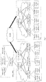
Fig. 1 schematically illustrates a network architecture diagram of an enterprise network shown in an exemplary example of the present disclosure. -
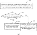
Fig. 2 illustrates a flow diagram of processing an ARP request packet by an aggregation switch shown in an exemplary example of the present disclosure. -
Fig. 3 illustrates a flow diagram of network access control processing on a user packet by an aggregation switch shown in an exemplary example of the present disclosure. -
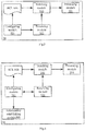
Fig. 4 schematically illustrates a hardware architecture diagram of a device for controlling network access shown in an exemplary example of the present disclosure. -
Fig. 5 schematically illustrates a structural diagram of a device for controlling network access shown in an exemplary example of the present disclosure. -
Fig. 6 schematically illustrates another structural diagram of a device for controlling network access shown in an exemplary example of the present disclosure. -
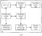
Fig. 7 schematically illustrates yet another structural diagram of a device for controlling network access shown in an exemplary example of the present disclosure. - Exemplary examples will be described in detail herein in conjunction with the figures. When the following descriptions involve the figures, like numerals in different figures represent like or similar elements unless otherwise stated. Examples described in the following exemplary examples are not all examples consistent with the present disclosure. On contrary, they are merely examples of a device and method consistent with some aspects of the present disclosure that are described in detail in the appended claims.
- The following examples of the present disclosure provide a method for controlling network access and a device to which the method may be applied.
- The examples of the present disclosure may be applied in an enterprise network. For example, the enterprise network may include several types of devices such as access switch, aggregation switch and core switch, wherein the core switch may be connected to the aggregation switch; the aggregation switch may be connected to the access switch, and the access switch may be used for enabling user access. The overlay technology may be applied to the aggregation switch and the core switch.
- In addition, an enterprise network may include a plurality of sub-networks. For example, as shown in
Fig. 1 , the enterprise network may include asub-network 1A and a sub-network IB. Thesub-network 1A includes:access switches 101a to 101e,aggregation switches 102a to 102c, andcore switches access switches 201a to 201e,aggregation switches 202a to 202c, andcore switches Fig. 1 , a data center may includedata center servers 104a to 104c and adata center switch 105a. - The overlay technology means overlaying a virtual network on an existing physical network, wherein the virtual network may be a virtual layer-2 network, thus leading to many advantages such as simplified configurations, user migrating and the like. Typical overlay technology mainly includes Virtual extensible LAN (VXLAN), Network Virtual Generic Routing Encapsulation (NVGRE), Stateless Transfer Tunnel (STT), etc.
- By using the overlay technology, the whole network may be constructed into a virtual layer-2 network, which, as shown in
Fig. 1 , may cover not only an enterprise network including multiple sub-networks, but also a Wide Area Network (WAN). Thus, thesub-networks - Taking VXLAN technology for example, in the enterprise network shown in
Fig. 1 , a VXLAN tunnel may be established between aggregation switches in the same sub-network, between aggregation switches in different sub-networks, between an aggregation switch and a core switch in the same sub-network, and between an aggregation switch and a core switch in different sub-networks. - On a control plane, an Ethernet VPN (EVPN) mechanism may be used to synchronize routing and Media Access Control (MAC) address information and suppress broadcasting of packets.
- A method of controlling network access provided by an example of the present disclosure may include contents as follows.
- A Software-Defined Network (SDN) controller may receive and save configuration information, wherein the configuration information includes user group information, resource group information, and various access control policies. The configuration information may be configured on the SDN controller in a static configuration way.
- The user group information may be shown as in Table 1, and the resource group information may be shown as in Table 2.
Table 1 User Group Identifier VLAN Identifier VXLAN Identifier Network Segment User Group 1 10 10 10.10.1.1/24 User Group 2 20 20 10.20.1.1/24 User Group 3 30 30 10.30.1.1/24 - As shown in Table 1, the user group information may include user group identifier, and Virtual Local Area Network (VLAN) identifier, VXLAN identifier and Network Segment, and it is apparent that one user group may correspond to one VLAN, one VXLAN and one network segment.
- All users may be grouped by user's identity. Apparently, users may also be grouped by other ways, such as user's age, user's locale, and the like, which is not limited in an example of the present disclosure. Users in the same user group may have the same network access authority, and users in different user groups may have different network access authorities.
Table 2 Resource Group Identifier IP Address of Data Center Server Resource Group 1 10.100.0.0/24 Resource Group 2 10.200.0,0/24 - As shown in Table 2, the resource group information may include resource group identifier and Internet Protocol (IP) address of data center server included in the resource group, wherein one resource group identifier may correspond to IP address of at least one data center server. When one resource group identifier corresponds to a plurality of IP addresses, these IP addresses may be all IP addresses in a network segment. For example, assuming that there are three servers a, b, c in a data center, resource group 1 may include server a, and resource group 2 may include servers b and c, wherein the IP addresses of servers b and c belong to the same network segment.
- Various access control policies may be visually represented as per Table 3.
Table 3 User group 1 User group 2 User group 3 Resource Group 1 Resource Group 2 User Group 1 deny User Group 2 deny deny User Group 3 deny deny - As shown in Table 3, various access control policies may include: an access control policy in the same user group, and/or an access control policy between different user groups, and/or an access control policy between a user group and a resource group. In table 3, if a mark "deny" is put in a position in the mth row and the nth column, it indicates that mutual access between users in a user group in the mth row and users in a user group in the nth column is prohibited, or indicates that access of a user group in the mth row to a data center server in a resource group in the nth column is prohibited. Wherein when a user group in the mth row and a user group in the nth column are the same user group, access control within the same user group is achieved. When a user group in the mth row and a user group in the nth column are not the same user group, access control between different user groups is achieved.
- Apparently, if the mark "deny" is absent in a position in the mth row and the nth column, it indicates that access is allowed.
- For example, in table 3, the mark "deny" present in the position in the 4th row and the 2nd column indicates that mutual access between users in user group 1 and users in user group 3 is prohibited; the mark "deny" present in the position in the 3rd row and the 3rd column indicates that mutual access between users in user group 2 is prohibited; the mark "deny" present in the position in the 2nd row and the 6th column indicates access of users in user group 1 to a data center server in resource group 2 is prohibited, and it thus can be seen in conjunction with Table 2 that access to a data center server with the IP address belonging to the network segment 10.200.0.0/24 is prohibited.
- A SDN controller may send contents in the user group information, the resource group information, and the various access control policies to various devices in a network, for example, access switch, aggregation switch, core switch, and Dynamic Host Configuration Protocol (DHCP) server, etc., such that they may proceed with configurations. The configuration process may be as shown below.
- The SDN controller may send VLAN identifiers corresponding to all user groups to all access switches. Each access switch may, after receiving a VLAN identifier, configure thereon the VLAN and configure an upstream port thereof in connection with an aggregation switch as being allowed to send a packet carrying the VLAN identifier. Thus, the access switch may send a packet encapsulated with the VLAN identifier via the upstream port.
- The SDN controller may send VLAN identifier corresponding to a user group to all aggregation switches. Each aggregation switch may, after receiving the VLAN identifier, configure thereon the VLAN and configure a downstream port thereof in connection with an access switch as being allowed to receive a packet carrying the VLAN identifier. Thus, the aggregation switch may receive a packet encapsulated with the VLAN identifier via the downstream port. The aggregation switch may configure VXLANs corresponding to all user groups and establish a corresponding relationship among VLAN, VXLAN and network segment. The aggregation switch may configure IP address and MAC address of gateway of VXLAN, wherein VXLAN virtual interface corresponding to VXLAN may be configured as gateway for corresponding network segment. Thus, each aggregation switch is configured with the gateways for all network segments. In this way, no matter where a user moves and which aggregation switch an access switch accesses, the aggregation switch is configured with a gateway for a network segment to which an IP address corresponding to the user belongs.
- The SDN controller may send VXLAN identifiers corresponding to all user groups to all core switches. Each core switch may, after receiving VXLAN identifier, configure thereon the VXLAN and a layer-3 gateway address thereof. In addition, a core switch may also configure routing connection with external devices, such as a data center switch and the like, by a routing protocol.
- The SDN controller may also send the various access control policies as shown in Table 3 to all aggregation switches. Each aggregation switch may, after receiving these contents, configure thereon corresponding ACL rule. An ACL rule includes: a first network segment and a second network segment, wherein the first network segment and the second network segment correspond to the same user group, or to different user groups; alternatively, the first network segment corresponds to a user group and the second network segment corresponds to a resource group.
- It thus can be seen that when the first network segment and the second network segment correspond to the same user group, the ACL rule may be used to prohibit mutual access between users in the same user group; when the first network segment and the second network segment correspond to different user groups, the ACL rule may be used to prohibit mutual access between users in different user groups; and when the first network segment corresponds to a user group and the second network segment corresponds to a resource group, the ACL rule may be used to prohibit access of users in the user group to a data center server in the resource group.
- For example, the ACL rules configured as per the access control policies as shown in Table 3 are shown below:
ACL1 deny source 10.10.1.1/24 destination 10.200.0.0/24 ACL2 deny source 10.20.1.1/24 destination 10.20.1.1/24 ACL3 deny source 10.20.1.1/24 destination 10.30.1.1/24 ACL4 deny source 10.30.1.1/24 destination 10.20.1.1/24 ACL5 deny source 10.30.1.1/24 destination 10.10.1.1/24 ACL6 deny source 10.10.1.1/24 destination 10.30.1.1/24 ACL7 deny source 10.30.1.1/24 destination 10.100.0.0/24 - ACL1 may be used to prohibit access of users in user group 1 to a data center server in resource group 2; ACL2 may be used to prohibit mutual access between users in user group 2; ACL3 and ACL4 may be used to prohibit mutual access between users in user group 2 and user group 3; ACL5 and ACL6 may be used to prohibit mutual access between users in user group 1 and user group 3; and ACL7 may be used to prohibit access of users in user group 3 to a data center server in resource group 1.
- The SDN controller may configure a corresponding relationship between user group and VLAN. In addition, an authentication server may also be configured with a corresponding relationship between user and user group; thus, a corresponding relationship among user, user group and VLAN may be saved on the authentication server.
- The SDN controller may send all network segments to a DHCP server, and configure a corresponding relationship between VLAN and address pool. IP address of each network segment may be saved in one address pool and a corresponding relationship between VLAN and address pool may be established.
- In order to achieve access control within the same user group, a port isolating function may be enabled on an access switch, and isolation between different virtual tunnels (a VLAN to which a physical port of an access switch belongs is transformed into a virtual tunnel on an aggregation switch) is enabled on an aggregation switch. Thus, a packet received by the access switch via a user port can only be forwarded to an aggregation switch via an upstream port in connection with the aggregation switch for performing network access control. In addition, as the port isolating function is enabled on the access switch, an Address Resolution Protocol (ARP) request packet sent by a user can only be forwarded to an aggregation switch, and therefore, each gateway on the aggregation switch may be configured with an ARP proxy function. Thus, the aggregation switch may, after receiving the ARP request packet, respond to the ARP request packet.
- After the above-described configuration process is completed, a user may carry on access authentication and access the network upon successful authentication.
- In the access authentication process of any user, the authentication server may determine a user group to which the user belongs, and may further determine a VLAN corresponding to the user group and send an identifier of the VLAN (i.e., the VLAN identifier) to an access switch; then, the access switch may, after receiving the VLAN identifier, add a user port thereof for access of the user to the VLAN. Subsequently, the user may make a request for an IP address. An aggregation switch may determine a VLAN to which the user port having received the address request packet belongs after receiving the address request packet from the user. Next, the aggregation switch may encapsulate the VLAN identifier in the address request packet and then send the address request packet to a DHCP server. When receiving the address request packet, the DHCP server may find a network segment corresponding to the VLAN identifier encapsulated in the address request packet, select one unoccupied IP address from the network segment and send a response packet which carries the selected IP address to the aggregation switch, and the response packet may be forwarded to the user via the aggregation switch so that the user can obtain an IP address in the network segment corresponding to the user group to which the user belongs.
- For any user, as long as a user group to which the user belongs remains unchanged, the user can obtain an IP address in a network segment corresponding to the user group no matter where the user accesses; that is, the user's IP address is always an IP address in the same network segment. Therefore, a packet sent by the user can always hit an ACL rule including the network segment.
- After obtaining the IP address and before sending a user packet to a data center server or another user with the IP address of IP1 (IP1 is a target IP address), the user may first obtain an MAC address corresponding to IP1. At this time, a determination may be made on whether IP1 and the user's IP address belong to the same network segment. If yes, an ARP request packet with a source IP address as the IP address of the user and a destination IP address as IP1 may be sent; and if no, an ARP request packet with the source IP address as the IP address of the user and the destination IP address as gateway IP address of a network segment to which the user's IP address belongs may be sent.
- The access switch may determine, after receiving the ARP request packet, a VLAN to which a user port having received the ARP request packet belongs, and may encapsulate an identifier of the VLAN in the ARP request packet. As the port isolating function is enabled, the access switch may send the ARP request packet to an aggregation switch.
- As shown in
Fig. 2 , the aggregation switch, after receiving the ARP request packet, may execute the following blocks. - At block S101, when receiving the ARP request packet sent by the access switch, the aggregation switch may determine a gateway for a network segment corresponding to a VLAN based on an identifier of the VLAN encapsulated in the ARP request packet.
- At block S102, the aggregation switch may determine whether a destination IP address of the ARP request packet is an IP address of the gateway determined in block S101, and if yes, block S103 is executed; otherwise, block S104 is executed.
- At block S103, the aggregation switch may send an ARP response packet carrying MAC address of the gateway to the access switch so as to forward the ARP response packet to the user via the access switch.
- At block S104, when the gateway is configured with an ARP proxy function, the aggregation switch may send the ARP response packet carrying the MAC address of the gateway to the access switch so as to forward the ARP response packet carrying the MAC address to the user via the access switch. When the gateway is not configured with the ARP proxy function, it is apparent that no response will be made.
- After the user terminal receives the ARP response packet, a corresponding relationship between IP1 and the MAC address of the gateway may be established. Subsequently, the user terminal may send a user packet with destination IP address as IP1 and destination MAC address as the MAC address of the gateway.
- A specific flow of carrying out network access control on the user packet is shown below.
- An access switch, after receiving the user packet, may determine a VLAN to which a user port having received the user packet belongs, encapsulate an identifier of the VLAN in the user packet and then forward the encapsulated packet to an aggregation switch.
- As shown in
Fig. 3 , the aggregation switch may, after receiving the user packet, execute the following blocks. - At block S201, when receiving the user packet, the aggregation switch may compare a source IP address of the user packet with a first network segment in an ACL rule, and compare a destination IP address of the user packet with a second network segment in the ACL rule.
- At block S201, if the source IP address of the user packet matches with the first network segment, and the destination IP address of the user packet matches with the second network segment, it indicates that the user packet hits the ALC rule. Otherwise, if the source IP address of the user packet does not match with the first network segment, and/or the destination IP address of the user packet does not match with the second network segment, it indicates that the user packet does not hit the ACL rule.
- At block S202, the aggregation switch may determine whether the user packet hits the ACL rule. If yes, block S203 is executed; otherwise, block S204 is executed.
- At block S203, the aggregation switch may discard the user packet.
- At block S204, the aggregation switch may forward the user packet.
- For example, in block S204, the aggregation switch may search a routing table for a corresponding egress interface based on the destination IP address of the user packet. If the found egress interface is a downstream port of the aggregation switch, the user packet may be forwarded via the found downstream port. If the found egress interface is a VXLAN tunnel interface, the aggregation switch may find out a VXLAN identifier corresponding to a VLAN identifier encapsulated in the user packet, and VXLAN-encapsulate the user packet and forward the encapsulated user packet.
- The VLAN mentioned in the above examples of the present disclosure refers to a VLAN corresponding to a user group.
- The method shown in the above examples of the present disclosure achieve the following technical effects.
- The overlay technology is applied to aggregation switch and core switch such that an overlay network architecture, i.e., a large virtual layer-2 network having the advantage of user migratability, is constructed.
- An aggregation switch is configured with ACL rule. The ACL rule includes: a first network segment and a second network segment, wherein the first network segment and the second network segment may correspond to the same user group or different user groups. In another example, the first network segment may correspond to a user group and the second network segment may correspond to a resource group. No matter where a user accesses, a VLAN corresponding to a user group to which the user belongs may be assigned to the user and an IP address in a network segment corresponding to the VLAN may be assigned to the user during access authentication. An aggregation switch may, after receiving a user packet from the user, matches the user packet with an ACL rule. If the user packet hits the ACL rule, it may be discarded. Thus, network access to a data center server in the resource group may be controlled, and network access within the same user group or between different user groups may also be controlled.
- As ACL rule is configured on aggregation switch instead of access switch and the number of the aggregation switches is obviously smaller than that of the access switches, the total number of the ACL rules to be configured may be reduced, thereby decreasing the configuration workload.
- As long as a user group to which the user belongs remains unchanged, the VLAN assigned to the user is unchanged, and so is a network segment to which the IP address assigned to the user belongs. Therefore, a user packet sent by the user can always hit an ACL rule including the network segment no matter where the user moves, and the ACL rule may not be impacted by change of the user's access position, thereby avoiding updating of the ACL rule caused by the change of the user's access position. Also, when there is a need to achieve network access control within the same user group, only one ACL rule is required, and at this time, the first network segment and the second network segment in the ACL rule both correspond to the user group; thus, the number of the ACL rules to be configured is greatly reduced and the ACL resources are saved.
- As an overlay network architecture is constructed, the method may be applied to a super-large-scale network and an across-WAN network.
- Corresponding to the example of the above-described method of controlling network access, an example of a device for controlling network access is also provided in the present disclosure.
- An example of a device for controlling network access of the present disclosure may be applied to an aggregation switch. The device example may be implemented by software or by hardware or a combination thereof. From hardware level, as shown in
Fig. 4 , illustrated is a hardware structure diagram of a device for controlling network access of the present disclosure. The device for controlling network access includes aprocessor 10 and a machine-readable storage medium 20. - Machine-readable instructions corresponding to a network access control logic are stored in the machine-readable storage medium 20.
- The
processor 10 communicates with the machine-readable storage medium 20 to read and execute the machine-readable instructions stored in the machine-readable storage medium 20, thereby implementing the method of controlling network access as described inFig. 3 . - As used herein, a "machine-readable storage medium" may be any electronic, magnetic, optical or other physical storage device to contain or store information such as executable instructions, data, and the like. For example, any machine-readable storage medium described herein may be any of a Random Access Memory (RAM), a volatile memory, a nonvolatile memory, a flash memory, a storage drive (e.g., hard drive), a solid state disk, any type of storage disc (e.g., compact disc, DVD, etc.), and the like, or a combination thereof.
- An example of the present disclosure also provides a device for controlling network access that may be applied to an aggregation switch. Referring to
Fig. 5 , thedevice 50 for controlling network access includes the following modules: - a configuring module 501 to configure an ACL rule on an aggregation switch, wherein the ACL rule includes: a first network segment and a second network segment, wherein the first network segment and the second network segment correspond to a same user group or different user groups; or the first network segment corresponds to a user group and the second network segment corresponds to a resource group;
- a
receiving module 502 to receive a user packet from a user terminal sent by an access switch; - a
matching module 503 to compare a source IP address of the user packet with the first network segment in the ACL rule and compare a destination IP address of the user packet with the second network segment in the ACL rule after thereceiving module 502 receives the user packet sent by the access switch, wherein the source IP address of the user packet is an IP address in a network segment corresponding to a Virtual Local Area Network (VLAN) associated with a user group to which the user terminal belongs; and - a
processing module 504 to discard the user packet when thematching module 503 determines that the source IP address of the user packet matches with the first network segment and the destination IP address of the user packet matches with the second network segment. - The receiving
module 502 is also to receive a VLAN identifier corresponding to a user group sent by an SDN controller. - After the
receiving module 502 receives the VLAN identifier, the configuring module 501 is also to configure a VLAN and a VXLAN corresponding to the user group on the aggregation switch based on the VLAN identifier, and also to configure a gateway IP address and an MAC address of the VXLAN. - As shown in
Fig. 6 , thedevice 50 for controlling network access also includes: arelationship establishing module 505 to establish a corresponding relationship among VLAN, VXLAN and network segment. - For example, if the
matching module 503 determines that the source IP address of the user packet does not match with the first network segment, or the destination IP address of the user packet does not match with the second network segment, theprocessing module 504 is also to search a routing table for a corresponding egress interface based on the destination IP address, and if the found egress interface is a downstream port of the device, forward the user packet via the found downstream port, and if the found egress interface is a VXLAN tunnel interface, search for a VXLAN identifier corresponding to the VLAN identifier encapsulated in the user packet and forward a VXLAN-encapsulated packet carried with the VXLAN identifier after performing VXLAN encapsulation for the user packet. - In addition, as shown in
Fig. 7 , theabove device 50 for controlling network access control also includes: agateway determining module 506 and a sendingmodule 507. - The receiving
module 502 is also to receive an ARP request packet for a target IP address from an access switch. - After the
receiving module 502 receives the ARP request packet, thegateway determining module 506 is to determine a gateway for a network segment corresponding to a VLAN based on a VLAN identifier of the VLAN, which is encapsulated in the ARP request packet. - If a destination IP address of the ARP request packet is the IP address of the determined gateway, the sending
module 507 is to send an ARP response packet carrying MAC address of the determined gateway to an access switch, and if the destination IP address of the ARP request packet is not the IP address of the determined gateway, send an ARP response packet carrying the MAC address of the gateway to an access switch when the determined gateway has an ARP proxy function, such that the user terminal, after receiving the ARP response packet forwarded by the access switch, establishes a corresponding relationship between the target IP address and the MAC address of the gateway and sends a user packet with the destination IP address as target IP address and the destination MAC address as MAC address of the determined gateway to the access switch. - In an example, when the target IP address and the source IP address of the ARP request packet belong to the same network segment, the
gateway determining module 506 determines the destination IP address of the ARP request packet as the target IP address; and when the target IP address and the source IP address of the ARP request packet belong to different network segments, the gateway determining module 606 determines the destination IP address of the ARP request packet as the IP address of the determined gateway. - The implementation process of functions and roles of various units in the above-described device is the same as the implementation process of corresponding blocks in the above-described method, which is not described redundantly herein.
- As the device examples basically correspond to the method examples, for correlations therebetween, reference may be made to part of descriptions of the method examples. The device examples described above are merely illustrative, wherein the units explained as separate members may be or may not be physically separate, and members displayed as units may be or may not be physical units, i.e., may be located in one place, or may be distributed to a plurality of a plurality of network units. Part of or all modules therein may be selected according to actual requirements to implement the objectives of the solutions of the present disclosure. Those of ordinary skill in the art may understand and carry out them without creative work.
- The terminology used in the present disclosure is merely for the purpose of describing specific examples, and not intended to limit the present disclosure. The singular form "a" , "said" and "the" used in the present disclosure and the appended claims are also intended to include the plural form unless clearly otherwise stated in context. It should also be understood that the term "and/or" used herein means including any or all possible combinations of one or more associated listed items.
- It should be understood that while terms "first", "second", "third" and the like may be used to describe various information in the present disclosure, the information should not be limited to these terms. These terms are merely used to distinguish the pieces of information of the same type. For example, without departing from the scope of the present disclosure, first information may also be referred to as second information, and similarly, second information may also be referred to as first information. Depending on the context, for example, the term "if' used herein may be interpreted as "in", "when" or "in response to determination".
- The foregoing descriptions are merely examples of the present disclosure, and not intended to limit the present disclosure. Any modifications, equivalent substitutions, improvements and the like made within the spirit and principles of the present disclosure are encompassed in the protection scope of the present disclosure.
Claims (12)
- A method for controlling network access, comprising:configuring, by an aggregation switch, an Access Control List, ACL, rule on the aggregation switch, wherein the ACL rule comprises a first network segment and a second network segment, and the first network segment and the second network segment correspond to a same user group or different user groups, or the first network segment corresponds to a user group and the second network segment corresponds to a resource group;receiving, by the aggregation switch, a user packet from a user terminal sent by an access switch;comparing, by the aggregation switch, a source Internet Protocol, IP, address of the user packet with the first network segment in the ACL rule and a destination IP address of the user packet with the second network segment in the ACL rule, wherein the source IP address of the user packet is an IP address in a network segment corresponding to a Virtual Local Area Network, VLAN, associated with a user group to which the user terminal belongs; anddiscarding, by the aggregation switch, the user packet when the source IP address of the user packet matches with the first network segment and the destination IP address of the user packet matches with the second network segment.
- The method according to claim 1, further comprising:receiving, by the aggregation switch, a VLAN identifier corresponding to a user group from a Software-Defined Network, SDN, controller;configuring, by the aggregation switch, VLAN and VXLAN corresponding to the user group on the aggregation switch;establishing a corresponding relationship among the VLAN, the VXLAN and a network segment; andconfiguring, by the aggregation switch, a gateway IP address and Media Access Control, MAC, address of the VXLAN.
- The method according to claim 2, further comprising:searching, by the aggregation switch, a routing table for a corresponding egress interface based on the destination IP address when the source IP address of the user packet does not match with the first network segment, or the destination IP address of the user packet does not match with the second network segment; andforwarding, by the aggregation switch, the user packet via a downstream port of the aggregation switch when the found egress interface is the downstream port;searching, by the aggregation switch, for a VXLAN identifier corresponding to a VLAN identifier encapsulated in the user packet when the found egress interface is a VXLAN tunnel interface; andobtaining, by the aggregation switch, a VXLAN-encapsulated packet carried with the VXLAN identifier by performing VXLAN encapsulation for the user packet, andforwarding the VXLAN-encapsulated packet.
- The method according to claim 2, further comprising:receiving, by the aggregation switch, an Address Resolution Protocol, ARP, request packet for a target IP address sent by the access switch before receiving the user packet sent by the access switch;determining, by the aggregation switch, a gateway for a network segment corresponding to a VLAN based on a VLAN identifier of the VLAN, which is encapsulated in the ARP request packet; anddetermining, by the aggregation switch, a destination IP address of the ARP request packet based on the target IP address and the source IP address of the ARP request packet.
- The method according to claim 4, further comprising:in case that the destination IP address of the ARP request packet is an IP address of the determined gateway,sending, by the aggregation switch, an ARP response packet carrying an MAC address of the determined gateway to the access switch; andin case that the destination IP address of the ARP request packet is not the IP address of the determined gateway,sending, by the aggregation switch, an ARP response packet carrying the MAC address of the determined gateway to the access switch when the determined gateway has an ARP proxy function, such that the user terminal, after receiving the ARP response packet sent by the access switch, establishes a corresponding relationship between the target IP address and the MAC address of the gateway and sends a user packet with a destination IP address as the target IP address and a destination MAC address as the MAC address of the determined gateway to the access switch.
- The method according to claim 4, wherein determining the destination IP address of the ARP request packet based on the target IP address and the source IP address of the ARP request packet comprises:determining, by the aggregation switch, the destination IP address of the ARP request packet as the target IP address when the target IP address and the source IP address of the ARP request packet belong to a same network segment; anddetermining, by the aggregation switch, the destination IP address of the ARP request packet as the IP address of the determined gateway when the target IP address and the source IP address of the ARP request packet belong to different network segments.
- A device for controlling network access, comprising a processor and a non-transitory machine-readable storage medium storing machine-readable instructions which are executable by the processor to:configure an Access Control List, ACL, rule on an aggregation switch, wherein the ACL rule comprises a first network segment and a second network segment, and the first network segment and the second network segment correspond to a same user group or different user groups, or the first network segment corresponds to a user group and the second network segment corresponds to a resource group;receive a user packet from a user terminal sent by an access switch;compare a source Internet Protocol, IP, address of the user packet with the first network segment in the ACL rule and a destination IP address of the user packet with the second network segment in the ACL rule, wherein the source IP address of the user packet is an IP address in a network segment corresponding to a Virtual Local Area Network, VLAN, associated with a user group to which the user terminal belongs; anddiscard the user packet when the source IP address of the user packet matches with the first network segment and the destination IP address of the user packet matches with the second network segment.
- The device according to claim 7, wherein the machine-readable instructions further cause the processor to:receive a VLAN identifier corresponding to a user group from a Software-Defined Network, SDN, controller;configure VLAN and VXLAN corresponding to the user group on the aggregation switch;establish a corresponding relationship among the VLAN, the VXLAN and a network segment; andconfigure a gateway IP address and Media Access Control, MAC, address of the VXLAN.
- The device according to claim 8, wherein the machine-readable instructions further cause the processor to:search a routing table for a corresponding egress interface based on the destination IP address when the source IP address of the user packet does not match with the first network segment, or the destination IP address of the user packet does not match with the second network segment;forward the user packet via a downstream port of the aggregation switch when the found egress interface is the downstream port;search for a VXLAN identifier corresponding to a VLAN identifier encapsulated in the user packet when the found egress interface is a VXLAN tunnel interface; andobtain a VXLAN-encapsulated packet carried with the VXLAN identifier by performing VXLAN encapsulation for the user packet, andforward the VXLAN-encapsulated packet.
- The device according to claim 8, wherein the machine-readable instructions further cause the processor to:receive an Address Resolution Protocol, ARP, request packet for a target IP address sent by the access switch before receiving the user packet sent by the access switch;determine a gateway for a network segment corresponding to a VLAN based on a VLAN identifier of the VLAN, which is encapsulated in the ARP request packet; anddetermine a destination IP address of the ARP request packet based on the target IP address and the source IP address of the ARP request packet.
- The device according to claim 10, wherein the machine-readable instructions further cause the processor to:in case that the destination IP address of the ARP request packet is an IP address of the determined gateway,send an ARP response packet carrying an MAC address of the determined gateway to the access switch; andin case that the destination IP address of the ARP request packet is not the IP address of the determined gateway,send an ARP response packet carrying the MAC address of the determined gateway to the access switch when the determined gateway has an ARP proxy function, such that the user terminal, after receiving the ARP response packet sent by the access switch, establishes a corresponding relationship between the target IP address and the MAC address of the gateway and sends a user packet with a destination IP address as the target IP address and a destination MAC address as the MAC address of the determined gateway to the access switch.
- The device according to claim 10, wherein when determining the destination IP address of the ARP request packet based on the target IP address and the source IP address of the ARP request packet, the processor is further caused by the machine-readable instructions to:determine the destination IP address of the ARP request packet as the target IP address when the target IP address and the source IP address of the ARP request packet belong to a same network segment; anddetermine the destination IP address of the ARP request packet as the IP address of the determined gateway when the target IP address and the source IP address of the ARP request packet belong to different network segments.
Applications Claiming Priority (2)
| Application Number | Priority Date | Filing Date | Title |
|---|---|---|---|
| CN201610288688.7A CN107332812B (en) | 2016-04-29 | 2016-04-29 | Method and device for realizing network access control |
| PCT/CN2017/082690 WO2017186181A1 (en) | 2016-04-29 | 2017-05-02 | Network access control |
Publications (3)
| Publication Number | Publication Date |
|---|---|
| EP3451612A1 true EP3451612A1 (en) | 2019-03-06 |
| EP3451612A4 EP3451612A4 (en) | 2019-03-20 |
| EP3451612B1 EP3451612B1 (en) | 2021-03-03 |
Family
ID=60161827
Family Applications (1)
| Application Number | Title | Priority Date | Filing Date |
|---|---|---|---|
| EP17788833.6A Active EP3451612B1 (en) | 2016-04-29 | 2017-05-02 | Network access control |
Country Status (5)
| Country | Link |
|---|---|
| US (1) | US11025631B2 (en) |
| EP (1) | EP3451612B1 (en) |
| JP (1) | JP6648308B2 (en) |
| CN (1) | CN107332812B (en) |
| WO (1) | WO2017186181A1 (en) |
Cited By (1)
| Publication number | Priority date | Publication date | Assignee | Title |
|---|---|---|---|---|
| EP4060957A4 (en) * | 2019-12-31 | 2023-03-01 | Huawei Technologies Co., Ltd. | ACCESS CONTROL METHOD, DEVICE AND SYSTEM |
Families Citing this family (82)
| Publication number | Priority date | Publication date | Assignee | Title |
|---|---|---|---|---|
| US10749711B2 (en) | 2013-07-10 | 2020-08-18 | Nicira, Inc. | Network-link method useful for a last-mile connectivity in an edge-gateway multipath system |
| US10454714B2 (en) | 2013-07-10 | 2019-10-22 | Nicira, Inc. | Method and system of overlay flow control |
| US10135789B2 (en) | 2015-04-13 | 2018-11-20 | Nicira, Inc. | Method and system of establishing a virtual private network in a cloud service for branch networking |
| US10498652B2 (en) | 2015-04-13 | 2019-12-03 | Nicira, Inc. | Method and system of application-aware routing with crowdsourcing |
| US10523636B2 (en) * | 2016-02-04 | 2019-12-31 | Airwatch Llc | Enterprise mobility management and network micro-segmentation |
| US20180219765A1 (en) | 2017-01-31 | 2018-08-02 | Waltz Networks | Method and Apparatus for Network Traffic Control Optimization |
| US11706127B2 (en) | 2017-01-31 | 2023-07-18 | Vmware, Inc. | High performance software-defined core network |
| US10778528B2 (en) | 2017-02-11 | 2020-09-15 | Nicira, Inc. | Method and system of connecting to a multipath hub in a cluster |
| US10523539B2 (en) | 2017-06-22 | 2019-12-31 | Nicira, Inc. | Method and system of resiliency in cloud-delivered SD-WAN |
| US11516049B2 (en) | 2017-10-02 | 2022-11-29 | Vmware, Inc. | Overlay network encapsulation to forward data message flows through multiple public cloud datacenters |
| US11115480B2 (en) | 2017-10-02 | 2021-09-07 | Vmware, Inc. | Layer four optimization for a virtual network defined over public cloud |
| US10999100B2 (en) | 2017-10-02 | 2021-05-04 | Vmware, Inc. | Identifying multiple nodes in a virtual network defined over a set of public clouds to connect to an external SAAS provider |
| FR3072529B1 (en) * | 2017-10-17 | 2019-10-18 | Sagemcom Broadband Sas | ROUTING DATA IN A RESIDENTIAL GATEWAY IMPLEMENTING LINK AGGREGATION |
| US11223514B2 (en) | 2017-11-09 | 2022-01-11 | Nicira, Inc. | Method and system of a dynamic high-availability mode based on current wide area network connectivity |
| CN108600170A (en) * | 2018-03-20 | 2018-09-28 | 大势至(北京)软件工程有限公司 | A kind of method and system of control multisegment environment lower network equipment internet behavior |
| CN110401726B (en) * | 2018-04-24 | 2022-04-15 | 中兴通讯股份有限公司 | Method, device and equipment for processing address resolution protocol message and storage medium |
| CN108616463B (en) * | 2018-04-25 | 2021-04-30 | 新华三技术有限公司 | Message processing method and switch |
| CN110446214A (en) * | 2018-05-03 | 2019-11-12 | 中兴通讯股份有限公司 | Method, device and device for managing network access process, and storage medium |
| CN110650076B (en) * | 2018-06-26 | 2021-12-24 | 华为技术有限公司 | VXLAN implementation method, network equipment and communication system |
| CN110650075B (en) * | 2018-06-26 | 2022-02-18 | 华为技术有限公司 | Group policy implementation method, network device and group policy implementation system based on VXLAN |
| CN109525601B (en) * | 2018-12-28 | 2021-04-27 | 杭州迪普科技股份有限公司 | Method and device for isolating transverse flow between terminals in intranet |
| CN111030970B (en) * | 2019-03-21 | 2023-04-18 | 安天科技集团股份有限公司 | Distributed access control method and device and storage equipment |
| CN111865876B (en) * | 2019-04-29 | 2021-10-15 | 华为技术有限公司 | Network access control method and device |
| US11171885B2 (en) | 2019-08-27 | 2021-11-09 | Vmware, Inc. | Providing recommendations for implementing virtual networks |
| CN110535744B (en) * | 2019-08-29 | 2021-12-24 | 新华三信息安全技术有限公司 | Message processing method and device and Leaf equipment |
| CN116208658A (en) * | 2019-09-06 | 2023-06-02 | 华为云计算技术有限公司 | Communication method, gateway, management method and device in hybrid cloud environment |
| CN112565158B (en) * | 2019-09-25 | 2022-10-04 | 阿里巴巴集团控股有限公司 | Data access method, device, system, electronic equipment and computer readable medium |
| CN110691101A (en) * | 2019-10-28 | 2020-01-14 | 锐捷网络股份有限公司 | Method and device for configuring an authentication-free list of dumb terminals |
| CN111130976B (en) * | 2019-11-15 | 2022-04-22 | 苏州浪潮智能科技有限公司 | Method, equipment and medium for configuring virtual local area network of white box switch |
| CN110838966B (en) * | 2019-11-20 | 2022-03-01 | 紫光华山科技有限公司 | Equipment connection control method and device |
| CN112838983B (en) * | 2019-11-22 | 2023-09-12 | 斑马智行网络(香港)有限公司 | Data transmission method, system, device, proxy server and storage medium |
| CN110958334B (en) * | 2019-11-25 | 2022-08-09 | 新华三半导体技术有限公司 | Message processing method and device |
| US11489783B2 (en) | 2019-12-12 | 2022-11-01 | Vmware, Inc. | Performing deep packet inspection in a software defined wide area network |
| CN111107142B (en) * | 2019-12-16 | 2022-07-01 | 新华三大数据技术有限公司 | Service access method and device |
| US11418997B2 (en) | 2020-01-24 | 2022-08-16 | Vmware, Inc. | Using heart beats to monitor operational state of service classes of a QoS aware network link |
| CN113645174B (en) * | 2020-04-27 | 2023-04-18 | 华为技术有限公司 | VXLAN access authentication method and VTEP device |
| CN111695149B (en) * | 2020-05-15 | 2023-07-28 | 浙江信网真科技股份有限公司 | Security filtering method based on cloud cooperation |
| US11245641B2 (en) | 2020-07-02 | 2022-02-08 | Vmware, Inc. | Methods and apparatus for application aware hub clustering techniques for a hyper scale SD-WAN |
| US11522754B2 (en) * | 2020-09-15 | 2022-12-06 | Arista Networks, Inc. | Systems and methods for Zero-Touch Provisioning of a switch in intermediate distribution frames and main distribution frames |
| US11444865B2 (en) | 2020-11-17 | 2022-09-13 | Vmware, Inc. | Autonomous distributed forwarding plane traceability based anomaly detection in application traffic for hyper-scale SD-WAN |
| US11575600B2 (en) | 2020-11-24 | 2023-02-07 | Vmware, Inc. | Tunnel-less SD-WAN |
| US11929903B2 (en) | 2020-12-29 | 2024-03-12 | VMware LLC | Emulating packet flows to assess network links for SD-WAN |
| US12218845B2 (en) | 2021-01-18 | 2025-02-04 | VMware LLC | Network-aware load balancing |
| US11792127B2 (en) | 2021-01-18 | 2023-10-17 | Vmware, Inc. | Network-aware load balancing |
| US11979325B2 (en) | 2021-01-28 | 2024-05-07 | VMware LLC | Dynamic SD-WAN hub cluster scaling with machine learning |
| CN112511569B (en) * | 2021-02-07 | 2021-05-11 | 杭州筋斗腾云科技有限公司 | Method and system for processing network resource access request and computer equipment |
| US12368676B2 (en) * | 2021-04-29 | 2025-07-22 | VMware LLC | Methods for micro-segmentation in SD-WAN for virtual networks |
| US12009987B2 (en) | 2021-05-03 | 2024-06-11 | VMware LLC | Methods to support dynamic transit paths through hub clustering across branches in SD-WAN |
| US11729065B2 (en) | 2021-05-06 | 2023-08-15 | Vmware, Inc. | Methods for application defined virtual network service among multiple transport in SD-WAN |
| US12015536B2 (en) | 2021-06-18 | 2024-06-18 | VMware LLC | Method and apparatus for deploying tenant deployable elements across public clouds based on harvested performance metrics of types of resource elements in the public clouds |
| US12250114B2 (en) | 2021-06-18 | 2025-03-11 | VMware LLC | Method and apparatus for deploying tenant deployable elements across public clouds based on harvested performance metrics of sub-types of resource elements in the public clouds |
| US11595232B1 (en) * | 2021-07-13 | 2023-02-28 | Paul Chang | Switch fabric for a data center network having virtual machines |
| US12047282B2 (en) | 2021-07-22 | 2024-07-23 | VMware LLC | Methods for smart bandwidth aggregation based dynamic overlay selection among preferred exits in SD-WAN |
| US12267364B2 (en) | 2021-07-24 | 2025-04-01 | VMware LLC | Network management services in a virtual network |
| US11943146B2 (en) | 2021-10-01 | 2024-03-26 | VMware LLC | Traffic prioritization in SD-WAN |
| CN114124896B (en) * | 2021-11-03 | 2023-08-08 | 中盈优创资讯科技有限公司 | Method and device for solving isolation of broadcasting domain between client and service system |
| CN114051246B (en) * | 2021-11-16 | 2024-02-20 | 酒泉钢铁(集团)有限责任公司 | SDN+VXLAN network and enterprise 5G network fusion-based method |
| US12603848B2 (en) | 2022-01-04 | 2026-04-14 | VMware LLC | Efficient mechanism for the transmission of multipath duplicate packets |
| US12184557B2 (en) | 2022-01-04 | 2024-12-31 | VMware LLC | Explicit congestion notification in a virtual environment |
| US12507120B2 (en) | 2022-01-12 | 2025-12-23 | Velocloud Networks, Llc | Heterogeneous hub clustering and application policy based automatic node selection for network of clouds |
| US12425395B2 (en) | 2022-01-15 | 2025-09-23 | VMware LLC | Method and system of securely adding an edge device operating in a public network to an SD-WAN |
| US12506678B2 (en) | 2022-01-25 | 2025-12-23 | VMware LLC | Providing DNS service in an SD-WAN |
| CN114520737B (en) * | 2022-01-26 | 2024-04-02 | 北京华信傲天网络技术有限公司 | Two-layer data access control method and system for wireless user |
| US12052288B2 (en) | 2022-03-08 | 2024-07-30 | Arista Networks, Inc. | Fallback segmentation security |
| US11909815B2 (en) | 2022-06-06 | 2024-02-20 | VMware LLC | Routing based on geolocation costs |
| US20240022626A1 (en) | 2022-07-18 | 2024-01-18 | Vmware, Inc. | Dns-based gslb-aware sd-wan for low latency saas applications |
| US12237990B2 (en) | 2022-07-20 | 2025-02-25 | VMware LLC | Method for modifying an SD-WAN using metric-based heat maps |
| CN115412319B (en) * | 2022-08-19 | 2024-03-26 | 浪潮思科网络科技有限公司 | Network authority control method, device and medium based on strategy following |
| US12489672B2 (en) | 2022-08-28 | 2025-12-02 | VMware LLC | Dynamic use of multiple wireless network links to connect a vehicle to an SD-WAN |
| US12425332B2 (en) | 2023-03-27 | 2025-09-23 | VMware LLC | Remediating anomalies in a self-healing network |
| US12057993B1 (en) | 2023-03-27 | 2024-08-06 | VMware LLC | Identifying and remediating anomalies in a self-healing network |
| US12034587B1 (en) | 2023-03-27 | 2024-07-09 | VMware LLC | Identifying and remediating anomalies in a self-healing network |
| US12355655B2 (en) | 2023-08-16 | 2025-07-08 | VMware LLC | Forwarding packets in multi-regional large scale deployments with distributed gateways |
| US12507148B2 (en) | 2023-08-16 | 2025-12-23 | Velocloud Networks, Llc | Interconnecting clusters in multi-regional large scale deployments with distributed gateways |
| US12483968B2 (en) | 2023-08-16 | 2025-11-25 | Velocloud Networks, Llc | Distributed gateways for multi-regional large scale deployments |
| US12507153B2 (en) | 2023-08-16 | 2025-12-23 | Velocloud Networks, Llc | Dynamic edge-to-edge across multiple hops in multi-regional large scale deployments with distributed gateways |
| US12261777B2 (en) | 2023-08-16 | 2025-03-25 | VMware LLC | Forwarding packets in multi-regional large scale deployments with distributed gateways |
| US12587468B2 (en) | 2023-08-16 | 2026-03-24 | Velocloud Networks, Llc | Route filtering for clusters in multi-regional large scale deployments with distributed gateways |
| US12563438B2 (en) | 2023-08-16 | 2026-02-24 | Velocloud Networks, Llc | Distributed gateways for multi-regional large scale deployments |
| US12603827B2 (en) | 2023-08-16 | 2026-04-14 | Velocloud Networks, Llc | Asymmetric routing resolutions in multi-regional large scale deployments with distributed gateways |
| CN120018135A (en) * | 2023-11-15 | 2025-05-16 | 锐捷网络股份有限公司 | Access method, policy accompanying method, transmission method, SDN controller and medium |
| CN119996305B (en) * | 2025-02-28 | 2025-12-05 | 新华三技术有限公司 | A traffic forwarding method, apparatus and related equipment |
Family Cites Families (39)
| Publication number | Priority date | Publication date | Assignee | Title |
|---|---|---|---|---|
| US7009933B2 (en) * | 2001-01-30 | 2006-03-07 | Broadcom Corporation | Traffic policing of packet transfer in a dual speed hub |
| CN100433750C (en) * | 2003-03-06 | 2008-11-12 | 华为技术有限公司 | A method of network access control based on user account |
| US8045566B2 (en) * | 2003-08-01 | 2011-10-25 | Hewlett-Packard Development Company, L.P. | Automated router load balancing |
| CN100586088C (en) * | 2006-07-20 | 2010-01-27 | 杭州华三通信技术有限公司 | Method for realizing virtual local area network aggregation and aggregation switch |
| CN101022394B (en) * | 2007-04-06 | 2010-05-26 | 杭州华三通信技术有限公司 | Method for realizing virtual local network aggregating and converging exchanger |
| CN101827008A (en) * | 2009-03-04 | 2010-09-08 | 中兴通讯股份有限公司 | Method for controlling refreshing frequency of Ethernet address table |
| WO2011150396A1 (en) * | 2010-05-28 | 2011-12-01 | Huawei Technologies Co., Ltd. | Virtual layer 2 and mechanism to make it scalable |
| EP2654255A4 (en) * | 2010-12-16 | 2017-08-16 | Nec Corporation | Switching device, higher-order device thereof, network and packet transfer method |
| JP5874726B2 (en) * | 2011-01-05 | 2016-03-02 | 日本電気株式会社 | Communication control system, control server, transfer node, communication control method, and communication control program |
| US8763075B2 (en) * | 2011-03-07 | 2014-06-24 | Adtran, Inc. | Method and apparatus for network access control |
| JP5395833B2 (en) * | 2011-03-14 | 2014-01-22 | 株式会社東芝 | Virtual network system and virtual communication control method |
| CN103460653A (en) * | 2011-03-31 | 2013-12-18 | 日本电气株式会社 | Computer system, and communication method |
| US8675664B1 (en) * | 2011-08-03 | 2014-03-18 | Juniper Networks, Inc. | Performing scalable L2 wholesale services in computer networks using customer VLAN-based forwarding and filtering |
| CN102255918A (en) * | 2011-08-22 | 2011-11-23 | 神州数码网络(北京)有限公司 | DHCP (Dynamic Host Configuration Protocol) Option 82 based user accessing authority control method |
| JP5484427B2 (en) * | 2011-10-27 | 2014-05-07 | 株式会社日立製作所 | Network system management method, network system, and management server |
| CN102404346A (en) * | 2011-12-27 | 2012-04-04 | 神州数码网络(北京)有限公司 | Method and system for controlling access authority of internet user |
| CA2775804C (en) * | 2012-05-08 | 2013-01-29 | Guest Tek Interactive Entertainment Ltd. | Automatically configuring computer network at hospitality establishment with reservation-specific settings |
| US8751650B2 (en) | 2012-05-10 | 2014-06-10 | Cisco Technology, Inc. | Method and apparatus for supporting access control lists in a multi-tenant environment |
| US9210079B2 (en) * | 2012-08-14 | 2015-12-08 | Vmware, Inc. | Method and system for virtual and physical network integration |
| JP6060688B2 (en) * | 2013-01-10 | 2017-01-18 | 富士通株式会社 | Transfer device, communication system, and roundabout path detection method |
| US20140233569A1 (en) * | 2013-02-15 | 2014-08-21 | Futurewei Technologies, Inc. | Distributed Gateway in Virtual Overlay Networks |
| US9325610B2 (en) * | 2013-03-15 | 2016-04-26 | Cisco Technology, Inc. | Extended tag networking |
| US9203738B2 (en) * | 2013-05-21 | 2015-12-01 | Cisco Technology, Inc. | Optimal forwarding for trill fine-grained labeling and VXLAN interworking |
| EP2993836B1 (en) * | 2013-06-14 | 2020-02-19 | Huawei Technologies Co., Ltd. | Method and device for routing data message |
| US9374323B2 (en) * | 2013-07-08 | 2016-06-21 | Futurewei Technologies, Inc. | Communication between endpoints in different VXLAN networks |
| CN104869065B (en) * | 2014-02-26 | 2020-04-21 | 中兴通讯股份有限公司 | Data message processing method and device |
| CN105471740B (en) * | 2014-07-09 | 2018-10-12 | 新华三技术有限公司 | Gateway based on software defined network migrates processing method and processing device |
| US9825878B2 (en) * | 2014-09-26 | 2017-11-21 | Cisco Technology, Inc. | Distributed application framework for prioritizing network traffic using application priority awareness |
| CN105450532B (en) * | 2014-09-28 | 2018-10-09 | 新华三技术有限公司 | Three-layer forwarding method in software defined network and device |
| CN105577548B (en) * | 2014-10-10 | 2018-10-09 | 新华三技术有限公司 | Message processing method and device in a kind of software defined network |
| US9781004B2 (en) * | 2014-10-16 | 2017-10-03 | Cisco Technology, Inc. | Discovering and grouping application endpoints in a network environment |
| CN105656796B (en) * | 2014-11-25 | 2019-01-22 | 新华三技术有限公司 | The method and apparatus for realizing three layers of virtual extended local area network forwarding |
| US9621577B2 (en) * | 2015-05-28 | 2017-04-11 | Microsoft Technology Licensing, Llc | Mitigation of computer network attacks |
| CN108353068B (en) * | 2015-10-20 | 2021-05-07 | 慧与发展有限责任合伙企业 | SDN controller assisted intrusion prevention system |
| US10298490B2 (en) * | 2015-12-09 | 2019-05-21 | Cisco Technology, Inc. | Coexistence and migration of legacy ethernet and overlay networks |
| US10432628B2 (en) * | 2016-02-23 | 2019-10-01 | Cisco Technology, Inc. | Method for improving access control for TCP connections while optimizing hardware resources |
| US10200278B2 (en) * | 2016-03-02 | 2019-02-05 | Arista Networks, Inc. | Network management system control service for VXLAN on an MLAG domain |
| US10142163B2 (en) * | 2016-03-07 | 2018-11-27 | Cisco Technology, Inc | BFD over VxLAN on vPC uplinks |
| US10270778B2 (en) * | 2016-03-21 | 2019-04-23 | Google Llc | Methods and systems for dynamic creation of access control lists |
-
2016
- 2016-04-29 CN CN201610288688.7A patent/CN107332812B/en active Active
-
2017
- 2017-05-02 EP EP17788833.6A patent/EP3451612B1/en active Active
- 2017-05-02 US US16/097,154 patent/US11025631B2/en active Active
- 2017-05-02 WO PCT/CN2017/082690 patent/WO2017186181A1/en not_active Ceased
- 2017-05-02 JP JP2018556323A patent/JP6648308B2/en active Active
Cited By (1)
| Publication number | Priority date | Publication date | Assignee | Title |
|---|---|---|---|---|
| EP4060957A4 (en) * | 2019-12-31 | 2023-03-01 | Huawei Technologies Co., Ltd. | ACCESS CONTROL METHOD, DEVICE AND SYSTEM |
Also Published As
| Publication number | Publication date |
|---|---|
| JP2019516320A (en) | 2019-06-13 |
| CN107332812A (en) | 2017-11-07 |
| EP3451612A4 (en) | 2019-03-20 |
| CN107332812B (en) | 2020-07-07 |
| WO2017186181A1 (en) | 2017-11-02 |
| US11025631B2 (en) | 2021-06-01 |
| JP6648308B2 (en) | 2020-02-14 |
| US20190132322A1 (en) | 2019-05-02 |
| EP3451612B1 (en) | 2021-03-03 |
Similar Documents
| Publication | Publication Date | Title |
|---|---|---|
| EP3451612B1 (en) | Network access control | |
| EP3499799B1 (en) | Forwarding policy configuration | |
| US10320838B2 (en) | Technologies for preventing man-in-the-middle attacks in software defined networks | |
| US11212262B2 (en) | Management of network access request based on source address of device | |
| EP3769471B1 (en) | On-demand security policy provisioning | |
| US11228558B2 (en) | Method and apparatus for isolating transverse communication between terminal devices in intranet | |
| US10237230B2 (en) | Method and system for inspecting network traffic between end points of a zone | |
| EP3461072B1 (en) | Access control in a vxlan | |
| EP3490197B1 (en) | Message forwarding | |
| EP2832053B1 (en) | L3 gateway for vxlan | |
| EP3499815A1 (en) | Packet transmission | |
| EP2905930A1 (en) | Processing method, apparatus and system for multicast | |
| US20150124823A1 (en) | Tenant dhcp in an overlay network | |
| EP3223476B1 (en) | Method, system, and apparatus for preventing tromboning in inter-subnet traffic within data center architectures | |
| EP3618366A1 (en) | Forwarding entry generation | |
| CN108600109B (en) | Message forwarding method and device | |
| US20130094514A1 (en) | Method and switch for sending packet | |
| CN105635190A (en) | Service execution method and device for data center network | |
| CA3157184A1 (en) | Group-based policies for inter-domain traffic | |
| US20190058692A1 (en) | Method and system for network traffic steering towards a service device | |
| JP6865266B2 (en) | Device detection method, SDN controller and storage medium | |
| EP3544251A1 (en) | Resource scheduling method | |
| CN107819776B (en) | Message processing method and device | |
| EP3618407B1 (en) | Method for implementing three-layer communication | |
| US11025536B1 (en) | Support for flooding in encapsulation and inter-VLAN communication via proxy-ARP |
Legal Events
| Date | Code | Title | Description |
|---|---|---|---|
| STAA | Information on the status of an ep patent application or granted ep patent |
Free format text: STATUS: THE INTERNATIONAL PUBLICATION HAS BEEN MADE |
|
| PUAI | Public reference made under article 153(3) epc to a published international application that has entered the european phase |
Free format text: ORIGINAL CODE: 0009012 |
|
| STAA | Information on the status of an ep patent application or granted ep patent |
Free format text: STATUS: REQUEST FOR EXAMINATION WAS MADE |
|
| 17P | Request for examination filed |
Effective date: 20181128 |
|
| AK | Designated contracting states |
Kind code of ref document: A1 Designated state(s): AL AT BE BG CH CY CZ DE DK EE ES FI FR GB GR HR HU IE IS IT LI LT LU LV MC MK MT NL NO PL PT RO RS SE SI SK SM TR |
|
| AX | Request for extension of the european patent |
Extension state: BA ME |
|
| A4 | Supplementary search report drawn up and despatched |
Effective date: 20190218 |
|
| RIC1 | Information provided on ipc code assigned before grant |
Ipc: H04L 12/715 20130101ALI20190212BHEP Ipc: H04L 12/46 20060101ALI20190212BHEP Ipc: H04L 29/06 20060101AFI20190212BHEP |
|
| DAV | Request for validation of the european patent (deleted) | ||
| DAX | Request for extension of the european patent (deleted) | ||
| RIC1 | Information provided on ipc code assigned before grant |
Ipc: H04L 29/06 20060101AFI20200804BHEP Ipc: H04L 12/851 20130101ALI20200804BHEP Ipc: H04L 12/715 20130101ALI20200804BHEP Ipc: H04L 12/46 20060101ALI20200804BHEP |
|
| GRAP | Despatch of communication of intention to grant a patent |
Free format text: ORIGINAL CODE: EPIDOSNIGR1 |
|
| STAA | Information on the status of an ep patent application or granted ep patent |
Free format text: STATUS: GRANT OF PATENT IS INTENDED |
|
| INTG | Intention to grant announced |
Effective date: 20200915 |
|
| GRAS | Grant fee paid |
Free format text: ORIGINAL CODE: EPIDOSNIGR3 |
|
| GRAA | (expected) grant |
Free format text: ORIGINAL CODE: 0009210 |
|
| STAA | Information on the status of an ep patent application or granted ep patent |
Free format text: STATUS: THE PATENT HAS BEEN GRANTED |
|
| AK | Designated contracting states |
Kind code of ref document: B1 Designated state(s): AL AT BE BG CH CY CZ DE DK EE ES FI FR GB GR HR HU IE IS IT LI LT LU LV MC MK MT NL NO PL PT RO RS SE SI SK SM TR |
|
| REG | Reference to a national code |
Ref country code: GB Ref legal event code: FG4D |
|
| REG | Reference to a national code |
Ref country code: AT Ref legal event code: REF Ref document number: 1368489 Country of ref document: AT Kind code of ref document: T Effective date: 20210315 Ref country code: CH Ref legal event code: EP |
|
| REG | Reference to a national code |
Ref country code: DE Ref legal event code: R096 Ref document number: 602017033921 Country of ref document: DE |
|
| REG | Reference to a national code |
Ref country code: IE Ref legal event code: FG4D |
|
| REG | Reference to a national code |
Ref country code: LT Ref legal event code: MG9D |
|
| PG25 | Lapsed in a contracting state [announced via postgrant information from national office to epo] |
Ref country code: NO Free format text: LAPSE BECAUSE OF FAILURE TO SUBMIT A TRANSLATION OF THE DESCRIPTION OR TO PAY THE FEE WITHIN THE PRESCRIBED TIME-LIMIT Effective date: 20210603 Ref country code: GR Free format text: LAPSE BECAUSE OF FAILURE TO SUBMIT A TRANSLATION OF THE DESCRIPTION OR TO PAY THE FEE WITHIN THE PRESCRIBED TIME-LIMIT Effective date: 20210604 Ref country code: FI Free format text: LAPSE BECAUSE OF FAILURE TO SUBMIT A TRANSLATION OF THE DESCRIPTION OR TO PAY THE FEE WITHIN THE PRESCRIBED TIME-LIMIT Effective date: 20210303 Ref country code: HR Free format text: LAPSE BECAUSE OF FAILURE TO SUBMIT A TRANSLATION OF THE DESCRIPTION OR TO PAY THE FEE WITHIN THE PRESCRIBED TIME-LIMIT Effective date: 20210303 Ref country code: BG Free format text: LAPSE BECAUSE OF FAILURE TO SUBMIT A TRANSLATION OF THE DESCRIPTION OR TO PAY THE FEE WITHIN THE PRESCRIBED TIME-LIMIT Effective date: 20210603 Ref country code: LT Free format text: LAPSE BECAUSE OF FAILURE TO SUBMIT A TRANSLATION OF THE DESCRIPTION OR TO PAY THE FEE WITHIN THE PRESCRIBED TIME-LIMIT Effective date: 20210303 |
|
| REG | Reference to a national code |
Ref country code: NL Ref legal event code: MP Effective date: 20210303 |
|
| REG | Reference to a national code |
Ref country code: AT Ref legal event code: MK05 Ref document number: 1368489 Country of ref document: AT Kind code of ref document: T Effective date: 20210303 |
|
| PG25 | Lapsed in a contracting state [announced via postgrant information from national office to epo] |
Ref country code: LV Free format text: LAPSE BECAUSE OF FAILURE TO SUBMIT A TRANSLATION OF THE DESCRIPTION OR TO PAY THE FEE WITHIN THE PRESCRIBED TIME-LIMIT Effective date: 20210303 Ref country code: PL Free format text: LAPSE BECAUSE OF FAILURE TO SUBMIT A TRANSLATION OF THE DESCRIPTION OR TO PAY THE FEE WITHIN THE PRESCRIBED TIME-LIMIT Effective date: 20210303 Ref country code: RS Free format text: LAPSE BECAUSE OF FAILURE TO SUBMIT A TRANSLATION OF THE DESCRIPTION OR TO PAY THE FEE WITHIN THE PRESCRIBED TIME-LIMIT Effective date: 20210303 Ref country code: SE Free format text: LAPSE BECAUSE OF FAILURE TO SUBMIT A TRANSLATION OF THE DESCRIPTION OR TO PAY THE FEE WITHIN THE PRESCRIBED TIME-LIMIT Effective date: 20210303 |
|
| PG25 | Lapsed in a contracting state [announced via postgrant information from national office to epo] |
Ref country code: NL Free format text: LAPSE BECAUSE OF FAILURE TO SUBMIT A TRANSLATION OF THE DESCRIPTION OR TO PAY THE FEE WITHIN THE PRESCRIBED TIME-LIMIT Effective date: 20210303 |
|
| PG25 | Lapsed in a contracting state [announced via postgrant information from national office to epo] |
Ref country code: AT Free format text: LAPSE BECAUSE OF FAILURE TO SUBMIT A TRANSLATION OF THE DESCRIPTION OR TO PAY THE FEE WITHIN THE PRESCRIBED TIME-LIMIT Effective date: 20210303 Ref country code: SM Free format text: LAPSE BECAUSE OF FAILURE TO SUBMIT A TRANSLATION OF THE DESCRIPTION OR TO PAY THE FEE WITHIN THE PRESCRIBED TIME-LIMIT Effective date: 20210303 Ref country code: CZ Free format text: LAPSE BECAUSE OF FAILURE TO SUBMIT A TRANSLATION OF THE DESCRIPTION OR TO PAY THE FEE WITHIN THE PRESCRIBED TIME-LIMIT Effective date: 20210303 Ref country code: EE Free format text: LAPSE BECAUSE OF FAILURE TO SUBMIT A TRANSLATION OF THE DESCRIPTION OR TO PAY THE FEE WITHIN THE PRESCRIBED TIME-LIMIT Effective date: 20210303 |
|
| REG | Reference to a national code |
Ref country code: DE Ref legal event code: R079 Ref document number: 602017033921 Country of ref document: DE Free format text: PREVIOUS MAIN CLASS: H04L0029060000 Ipc: H04L0065000000 |
|
| PG25 | Lapsed in a contracting state [announced via postgrant information from national office to epo] |
Ref country code: IS Free format text: LAPSE BECAUSE OF FAILURE TO SUBMIT A TRANSLATION OF THE DESCRIPTION OR TO PAY THE FEE WITHIN THE PRESCRIBED TIME-LIMIT Effective date: 20210703 Ref country code: RO Free format text: LAPSE BECAUSE OF FAILURE TO SUBMIT A TRANSLATION OF THE DESCRIPTION OR TO PAY THE FEE WITHIN THE PRESCRIBED TIME-LIMIT Effective date: 20210303 Ref country code: SK Free format text: LAPSE BECAUSE OF FAILURE TO SUBMIT A TRANSLATION OF THE DESCRIPTION OR TO PAY THE FEE WITHIN THE PRESCRIBED TIME-LIMIT Effective date: 20210303 Ref country code: PT Free format text: LAPSE BECAUSE OF FAILURE TO SUBMIT A TRANSLATION OF THE DESCRIPTION OR TO PAY THE FEE WITHIN THE PRESCRIBED TIME-LIMIT Effective date: 20210705 |
|
| REG | Reference to a national code |
Ref country code: DE Ref legal event code: R097 Ref document number: 602017033921 Country of ref document: DE |
|
| REG | Reference to a national code |
Ref country code: CH Ref legal event code: PL |
|
| PLBE | No opposition filed within time limit |
Free format text: ORIGINAL CODE: 0009261 |
|
| STAA | Information on the status of an ep patent application or granted ep patent |
Free format text: STATUS: NO OPPOSITION FILED WITHIN TIME LIMIT |
|
| PG25 | Lapsed in a contracting state [announced via postgrant information from national office to epo] |
Ref country code: ES Free format text: LAPSE BECAUSE OF FAILURE TO SUBMIT A TRANSLATION OF THE DESCRIPTION OR TO PAY THE FEE WITHIN THE PRESCRIBED TIME-LIMIT Effective date: 20210303 Ref country code: DK Free format text: LAPSE BECAUSE OF FAILURE TO SUBMIT A TRANSLATION OF THE DESCRIPTION OR TO PAY THE FEE WITHIN THE PRESCRIBED TIME-LIMIT Effective date: 20210303 Ref country code: CH Free format text: LAPSE BECAUSE OF NON-PAYMENT OF DUE FEES Effective date: 20210531 Ref country code: AL Free format text: LAPSE BECAUSE OF FAILURE TO SUBMIT A TRANSLATION OF THE DESCRIPTION OR TO PAY THE FEE WITHIN THE PRESCRIBED TIME-LIMIT Effective date: 20210303 Ref country code: LI Free format text: LAPSE BECAUSE OF NON-PAYMENT OF DUE FEES Effective date: 20210531 Ref country code: MC Free format text: LAPSE BECAUSE OF FAILURE TO SUBMIT A TRANSLATION OF THE DESCRIPTION OR TO PAY THE FEE WITHIN THE PRESCRIBED TIME-LIMIT Effective date: 20210303 Ref country code: LU Free format text: LAPSE BECAUSE OF NON-PAYMENT OF DUE FEES Effective date: 20210502 |
|
| 26N | No opposition filed |
Effective date: 20211206 |
|
| REG | Reference to a national code |
Ref country code: BE Ref legal event code: MM Effective date: 20210531 |
|
| PG25 | Lapsed in a contracting state [announced via postgrant information from national office to epo] |
Ref country code: SI Free format text: LAPSE BECAUSE OF FAILURE TO SUBMIT A TRANSLATION OF THE DESCRIPTION OR TO PAY THE FEE WITHIN THE PRESCRIBED TIME-LIMIT Effective date: 20210303 |
|
| PG25 | Lapsed in a contracting state [announced via postgrant information from national office to epo] |
Ref country code: IT Free format text: LAPSE BECAUSE OF FAILURE TO SUBMIT A TRANSLATION OF THE DESCRIPTION OR TO PAY THE FEE WITHIN THE PRESCRIBED TIME-LIMIT Effective date: 20210303 Ref country code: IE Free format text: LAPSE BECAUSE OF NON-PAYMENT OF DUE FEES Effective date: 20210502 |
|
| PG25 | Lapsed in a contracting state [announced via postgrant information from national office to epo] |
Ref country code: IS Free format text: LAPSE BECAUSE OF FAILURE TO SUBMIT A TRANSLATION OF THE DESCRIPTION OR TO PAY THE FEE WITHIN THE PRESCRIBED TIME-LIMIT Effective date: 20210703 |
|
| PG25 | Lapsed in a contracting state [announced via postgrant information from national office to epo] |
Ref country code: BE Free format text: LAPSE BECAUSE OF NON-PAYMENT OF DUE FEES Effective date: 20210531 |
|
| P01 | Opt-out of the competence of the unified patent court (upc) registered |
Effective date: 20230424 |
|
| PG25 | Lapsed in a contracting state [announced via postgrant information from national office to epo] |
Ref country code: CY Free format text: LAPSE BECAUSE OF FAILURE TO SUBMIT A TRANSLATION OF THE DESCRIPTION OR TO PAY THE FEE WITHIN THE PRESCRIBED TIME-LIMIT Effective date: 20210303 |
|
| PG25 | Lapsed in a contracting state [announced via postgrant information from national office to epo] |
Ref country code: HU Free format text: LAPSE BECAUSE OF FAILURE TO SUBMIT A TRANSLATION OF THE DESCRIPTION OR TO PAY THE FEE WITHIN THE PRESCRIBED TIME-LIMIT; INVALID AB INITIO Effective date: 20170502 |
|
| PG25 | Lapsed in a contracting state [announced via postgrant information from national office to epo] |
Ref country code: MK Free format text: LAPSE BECAUSE OF FAILURE TO SUBMIT A TRANSLATION OF THE DESCRIPTION OR TO PAY THE FEE WITHIN THE PRESCRIBED TIME-LIMIT Effective date: 20210303 |
|
| PG25 | Lapsed in a contracting state [announced via postgrant information from national office to epo] |
Ref country code: TR Free format text: LAPSE BECAUSE OF FAILURE TO SUBMIT A TRANSLATION OF THE DESCRIPTION OR TO PAY THE FEE WITHIN THE PRESCRIBED TIME-LIMIT Effective date: 20210303 |
|
| PG25 | Lapsed in a contracting state [announced via postgrant information from national office to epo] |
Ref country code: MT Free format text: LAPSE BECAUSE OF FAILURE TO SUBMIT A TRANSLATION OF THE DESCRIPTION OR TO PAY THE FEE WITHIN THE PRESCRIBED TIME-LIMIT Effective date: 20210303 |
|
| PGFP | Annual fee paid to national office [announced via postgrant information from national office to epo] |
Ref country code: DE Payment date: 20250122 Year of fee payment: 9 |
|
| PGFP | Annual fee paid to national office [announced via postgrant information from national office to epo] |
Ref country code: GB Payment date: 20260323 Year of fee payment: 10 |
|
| PGFP | Annual fee paid to national office [announced via postgrant information from national office to epo] |
Ref country code: FR Payment date: 20260317 Year of fee payment: 10 |