US11212262B2 - Management of network access request based on source address of device - Google Patents
Management of network access request based on source address of device Download PDFInfo
- Publication number
- US11212262B2 US11212262B2 US16/805,368 US202016805368A US11212262B2 US 11212262 B2 US11212262 B2 US 11212262B2 US 202016805368 A US202016805368 A US 202016805368A US 11212262 B2 US11212262 B2 US 11212262B2
- Authority
- US
- United States
- Prior art keywords
- networking
- gateway
- network
- access
- address
- Prior art date
- Legal status (The legal status is an assumption and is not a legal conclusion. Google has not performed a legal analysis and makes no representation as to the accuracy of the status listed.)
- Active, expires
Links
Images


Classifications
-
- H—ELECTRICITY
- H04—ELECTRIC COMMUNICATION TECHNIQUE
- H04L—TRANSMISSION OF DIGITAL INFORMATION, e.g. TELEGRAPHIC COMMUNICATION
- H04L12/00—Data switching networks
- H04L12/28—Data switching networks characterised by path configuration, e.g. LAN [Local Area Networks] or WAN [Wide Area Networks]
- H04L12/46—Interconnection of networks
- H04L12/4641—Virtual LANs, VLANs, e.g. virtual private networks [VPN]
-
- H—ELECTRICITY
- H04—ELECTRIC COMMUNICATION TECHNIQUE
- H04L—TRANSMISSION OF DIGITAL INFORMATION, e.g. TELEGRAPHIC COMMUNICATION
- H04L63/00—Network architectures or network communication protocols for network security
- H04L63/02—Network architectures or network communication protocols for network security for separating internal from external traffic, e.g. firewalls
- H04L63/029—Firewall traversal, e.g. tunnelling or, creating pinholes
-
- H—ELECTRICITY
- H04—ELECTRIC COMMUNICATION TECHNIQUE
- H04L—TRANSMISSION OF DIGITAL INFORMATION, e.g. TELEGRAPHIC COMMUNICATION
- H04L12/00—Data switching networks
- H04L12/28—Data switching networks characterised by path configuration, e.g. LAN [Local Area Networks] or WAN [Wide Area Networks]
- H04L12/46—Interconnection of networks
- H04L12/4633—Interconnection of networks using encapsulation techniques, e.g. tunneling
-
- H—ELECTRICITY
- H04—ELECTRIC COMMUNICATION TECHNIQUE
- H04L—TRANSMISSION OF DIGITAL INFORMATION, e.g. TELEGRAPHIC COMMUNICATION
- H04L12/00—Data switching networks
- H04L12/66—Arrangements for connecting between networks having differing types of switching systems, e.g. gateways
-
- H—ELECTRICITY
- H04—ELECTRIC COMMUNICATION TECHNIQUE
- H04L—TRANSMISSION OF DIGITAL INFORMATION, e.g. TELEGRAPHIC COMMUNICATION
- H04L45/00—Routing or path finding of packets in data switching networks
- H04L45/50—Routing or path finding of packets in data switching networks using label swapping, e.g. multi-protocol label switch [MPLS]
-
- H—ELECTRICITY
- H04—ELECTRIC COMMUNICATION TECHNIQUE
- H04L—TRANSMISSION OF DIGITAL INFORMATION, e.g. TELEGRAPHIC COMMUNICATION
- H04L45/00—Routing or path finding of packets in data switching networks
- H04L45/54—Organization of routing tables
-
- H—ELECTRICITY
- H04—ELECTRIC COMMUNICATION TECHNIQUE
- H04L—TRANSMISSION OF DIGITAL INFORMATION, e.g. TELEGRAPHIC COMMUNICATION
- H04L45/00—Routing or path finding of packets in data switching networks
- H04L45/72—Routing based on the source address
-
- H—ELECTRICITY
- H04—ELECTRIC COMMUNICATION TECHNIQUE
- H04L—TRANSMISSION OF DIGITAL INFORMATION, e.g. TELEGRAPHIC COMMUNICATION
- H04L45/00—Routing or path finding of packets in data switching networks
- H04L45/74—Address processing for routing
-
- H—ELECTRICITY
- H04—ELECTRIC COMMUNICATION TECHNIQUE
- H04L—TRANSMISSION OF DIGITAL INFORMATION, e.g. TELEGRAPHIC COMMUNICATION
- H04L63/00—Network architectures or network communication protocols for network security
- H04L63/02—Network architectures or network communication protocols for network security for separating internal from external traffic, e.g. firewalls
- H04L63/0227—Filtering policies
- H04L63/0263—Rule management
-
- H—ELECTRICITY
- H04—ELECTRIC COMMUNICATION TECHNIQUE
- H04L—TRANSMISSION OF DIGITAL INFORMATION, e.g. TELEGRAPHIC COMMUNICATION
- H04L63/00—Network architectures or network communication protocols for network security
- H04L63/02—Network architectures or network communication protocols for network security for separating internal from external traffic, e.g. firewalls
- H04L63/0272—Virtual private networks
-
- H—ELECTRICITY
- H04—ELECTRIC COMMUNICATION TECHNIQUE
- H04L—TRANSMISSION OF DIGITAL INFORMATION, e.g. TELEGRAPHIC COMMUNICATION
- H04L63/00—Network architectures or network communication protocols for network security
- H04L63/08—Network architectures or network communication protocols for network security for authentication of entities
-
- H—ELECTRICITY
- H04—ELECTRIC COMMUNICATION TECHNIQUE
- H04L—TRANSMISSION OF DIGITAL INFORMATION, e.g. TELEGRAPHIC COMMUNICATION
- H04L63/00—Network architectures or network communication protocols for network security
- H04L63/10—Network architectures or network communication protocols for network security for controlling access to devices or network resources
-
- H—ELECTRICITY
- H04—ELECTRIC COMMUNICATION TECHNIQUE
- H04W—WIRELESS COMMUNICATION NETWORKS
- H04W48/00—Access restriction; Network selection; Access point selection
- H04W48/16—Discovering, processing access restriction or access information
-
- H—ELECTRICITY
- H04—ELECTRIC COMMUNICATION TECHNIQUE
- H04W—WIRELESS COMMUNICATION NETWORKS
- H04W76/00—Connection management
- H04W76/10—Connection setup
- H04W76/12—Setup of transport tunnels
-
- H—ELECTRICITY
- H04—ELECTRIC COMMUNICATION TECHNIQUE
- H04W—WIRELESS COMMUNICATION NETWORKS
- H04W48/00—Access restriction; Network selection; Access point selection
- H04W48/18—Selecting a network or a communication service
-
- H—ELECTRICITY
- H04—ELECTRIC COMMUNICATION TECHNIQUE
- H04W—WIRELESS COMMUNICATION NETWORKS
- H04W88/00—Devices specially adapted for wireless communication networks, e.g. terminals, base stations or access point devices
- H04W88/16—Gateway arrangements
Definitions
- Various example embodiments relate to providing network access to a networking device.
- a networking device When a networking device is plugged into a local network, it can, in principle, access all other communication devices within the local network. To access other networks, for example another subnet, network segment or the Internet, the communication device has to traverse gateway devices that connect the local network with the other networks.
- NAC Network Access Control
- VPN Virtual Private Networking
- a problem with the above identified access mechanisms is that they rely heavily on the underlying network topology. Therefore, access rules for a device or corresponding user must be translated into the physical topology of the underlying network. For large enterprise networks, a newly-added communication device may trigger a change in firewall and networking rules in a multitude of networking devices before the communication can even access the network segments it is allowed access to. The other way around, a change in the network topology results in a reconfiguration of the networking devices in order to maintain the existing network security.
- Example embodiments of the present disclosure foresee, amongst others, a solution to this identified problem.
- a method comprising the following steps:
- the first gateway which acts as the default gateway for the networking device, only provides the networking device access beyond the local network by dedicated networking tunnels (e.g., for each connection with a certain network segment, a dedicated networking tunnel is created that is used only for network traffic between the networking device and the respective network segment).
- the gateway further performs a source based routing to forward packets from the networking device to the correct networking tunnel. This avoids having multiple routes to a certain segment by having different accessible tunnels.
- network access beyond the local network of the first networking device is defined by the access rules and implemented by the networking tunnels.
- the network access beyond the local network is thus independent from the underlying network topology.
- the access control does not require any intervention from the networking device (e.g., no special software is needed on the networking device).
- the networking device may also be a headless device such as a printer, telephone, projector or any IoT device.
- the providing the one or more dedicated networking tunnels further comprises providing a dedicated routing table for the first networking device for performing the routing the networking packets to a selection of the one or more dedicated networking tunnels.
- the setting up further comprises providing a dedicated network container for the networking device in the default gateway; and wherein the routing comprises forwarding the networking packets to the dedicated network container.
- the dedicated network container may then further comprise the dedicated routing table.
- the method further comprises:
- the method further comprises:
- the method further comprises:
- the method further comprises:
- the method further comprises:
- the method further comprises:
- the network address request of the first networking device comprises a hardware address associated with the first networking device; and wherein the determining further comprises:
- the method further comprises:
- the method further comprises:
- a networking device comprising means for performing the steps as performed by the first and/or second gateway according to the first example aspect.
- a computer program product comprising computer-executable instructions for causing a networking device to perform the steps according to the first example aspect.
- a computer readable storage medium comprising computer-executable instructions for performing the steps according to the first example aspect when the program is run on a computer.
- FIG. 1 shows an example embodiment of a secured communication network
- FIG. 2 shows another example embodiment of a secured communication network
- FIG. 3 shows a sequence diagram for establishing networking tunnels in a secured communication network according to an example embodiment
- FIG. 4 shows a sequence diagram for establishing networking tunnels in a secured communication network according to a further example embodiment
- FIG. 5 shows a sequence diagram for providing hardware address of a default gateway to a networking device according to an example embodiment
- FIG. 6 shows a sequence diagram for providing a networking device with a different default gateway according to an example embodiment
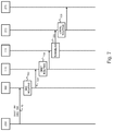
- FIG. 7 shows a sequence diagram for forwarding a networking packet from a source communication device to a destination communication device
- FIG. 8 shows a sequence diagram for determining access rules by a host configuration component and an authentication component according to an embodiment
- FIG. 9 illustrates steps performed by an authentication component for determining access rules comprising a tunnel list and an access list
- FIG. 10 shows an example embodiment of a suitable computing system for performing one or several steps according to various example embodiments.
- Network communication relates to the exchange of networking packets according to a network addressing scheme.
- network communication refers to a communication scheme or protocol at the networking layer.
- Some examples are the Internet Protocol comprising the Internet Protocol version 4 or IPv4 and the Internet Protocol version 6 or IPv6.
- a networking device is typically assigned with a network address either statically or dynamically. When a networking packet is forwarded from a source networking device to a destination networking device, the packet is forwarded along a series of intermediated devices.
- a communication network may further comprise a gateway that connects the network with other communication networks or network segments, such as for example with the Internet, with another private network, or with another subnet.
- link layer packets When network packets are forwarded along a communication network, they are further encapsulated in link layer packets for communication to the next networking node using physical or hardware addressing schemes.
- link layer addressing scheme is specified in the IEEE 802 protocol which uses so-called media access control address, or shortly MAC addresses.
- FIG. 1 illustrates an example of a secured segmented communication network 105 according to an embodiment.
- the security is provided by segment access controller 100 , further referred to as access controller or AC.
- access controller 100 network access by networking devices 150 to 156 to network segments 171 , 181 and 191 is secured.
- access controller 100 establishes networking tunnels 170 , 180 , 190 to the different network segments 171 , 181 , 191 .
- a dedicated distinct networking tunnel is established between the access controller 100 and the respective network segment thereby adding the respective networking devices to the network segments (e.g., making them accessible by devices in the respective segments and vice versa).
- Access controller 100 serves as the default gateway for the connected networking devices 151 - 156 . This way, network traffic between a network segment and a respective networking device is then routed along such a dedicated tunnel. To this respect, access controller 100 maintains separate routing tables for each of the connected networking devices 151 - 156 .
- networking devices may only communicate in an east-west fashion without control of the access controller 100 , for example, within the boundaries of the local network segment 101 , as defined by a network switch 141 by which the networking devices are connected.
- East-west data traffic may further be restricted by allowing networking devices 151 - 156 to only communicate with the networking port to which the access controller 100 is connected (e.g., by assigning the ports of the switch 141 to different virtual local area networks or VLANs).
- FIG. 2 illustrates a more general representation of the working principle of the access controller 100 of FIG. 1 .
- networking devices 250 to 253 are used as an example of networking devices for which network control and access is to be provided by access controllers 100 , 200 to the network segments 271 , 281 , 291 .
- Each network segment 271 , 281 , 291 is accessible by at least one respective gateway 270 , 280 , 290 .
- Networking device 250 is provided network access to network segments 271 and 281 . This is done by a networking tunnel 120 between access controller 100 and gateway 270 and by a networking tunnel 122 between access controller 100 and gateway 280 .
- virtual networking interfaces 111 and 112 are present at the access controller 100 and virtual networking interfaces 272 and 282 are present at the respective gateways 270 and 280 .
- device 251 has network access to network segment 271 by the networking tunnel 121 between the interface 113 at the access controller 100 and the interface 273 and gateway 270 ;
- device 253 has network access to network segment 291 by the networking tunnel 224 between the interface 214 at the access controller 200 and the interface 293 at the gateway 290 ;
- device 252 has network access to network segment 291 by the networking tunnel 223 between the interface 213 at the access controller 200 and the interface 292 at the gateway 290 , and has network access to network segment 281 by the networking tunnel 222 between the interface 212 at the access controller 200 and the interface 283 at the gateway 280 , and has network access to network segment 271 by the networking tunnel 212 between the interface 211 at the access controller 200 and the interface 274 at the gateway 270 .
- the access controllers 100 , 200 perform source based routing. For example, when a network packet arrives at access controller 100 , it first checks the source address of the packet to decide to which set of networking tunnels the packet should be forwarded (e.g., to interface 115 or 116 ). Thereafter, the access controller 100 performs destination based routing to forward the packet to the correct networking tunnel.
- networking devices within one of the segments may establish a connection with a networking device 250 - 253 when the networking device is present in the respective segment.
- a networking device 275 may establish a network connection with any one of networking devices 250 to 252 .
- networking device 275 sends a packet to gateway 270 .
- Gateway 270 on its turn routes the packet by interface 272 , over tunnel 120 to interface 111 .
- interface 111 is dedicated to networking device 250
- the packet is forwarded further by access controller 100 to networking device 250 .
- any networking device that connects to a local network 201 can be provided access to any network segment in a safe and secure manner. Because of the dedicated tunnels, any network access of the networking devices outside the local network 201 is managed by the access controllers 100 , 200 . In other words, there is no need to protect the network infrastructure beyond the 1-hop boundary of the networking devices 250 - 253 (e.g., beyond the switching logic that connects the networking devices with the access controllers 100 , 200 ).
- FIGS. 3 to 8 show different sequence diagrams illustrating the establishing and maintaining of the segmented network layout as illustrated by FIG. 1 and FIG. 2 . For sake of clarity, further reference is made to the networking components of FIG. 2 .
- FIG. 3 shows a sequence diagram for adding networking device 250 to network segments 271 and 281 .
- communication device 250 connects to the local network 201 and requests a network address (e.g., by a broadcast message onto the local network 201 ).
- the request 302 is received by an authentication service 300 that is accessible from the local network 201 .
- the authentication service 300 determines in step 303 a network address and an address of a default gateway for the networking device.
- the default gateway serves as the networking device for communicating outside local network 201 (e.g., the default gateway corresponds to access controller 100 ).
- the network address of the communication device 250 and of the access controller 100 is sent as a return packet 304 to communication device 250 .
- authentication service 300 Upon the request 302 , authentication service 300 also determines access rules for the communication device 250 under step 304 .
- the access rules comprise the identification of communication device 250 (e.g., the hardware and network address of communication device 250 ) and access information on how to connect to network segments 271 , 281 .
- This access information may for example comprise a network address of the remote gateways 270 , 280 , authentication information for setting up the respective tunnels 120 , 122 , encryption information for encrypting the networking packets exchanged over the respective tunnels 120 , 122 and firewalls rules to apply at the respective gateways 270 , 280 .
- the access rules 305 are provided to the access controller 100 .
- access controller 100 Upon receiving the access rules 305 , access controller 100 establishes the networking tunnels 120 , 122 in a next step 306 .
- FIG. 4 illustrates steps performed by access controller 100 for setting up the networking tunnels 120 , 122 under step 306 of FIG. 3 according to a further embodiment.
- access controller 100 receives the access rules from authentication service 300 .
- access controller 100 first creates a virtual networking device 117 with a dedicated networking interface 115 for communication device 250 .
- the virtual networking device 117 is implemented by creating a network container (e.g., an operating-system-level virtualized instance running a separate networking stack).
- a network container e.g., an operating-system-level virtualized instance running a separate networking stack.
- Such operating-system-level virtualization also referred to as containerization, is for example provided by the Docker software and available for Linux, Windows and macOS based operating systems.
- access controller 100 may also instantiate a virtual machine (e.g., an emulated computer system) associated with the communication device 250 with its own communication interface.
- a virtual routing table is also created for the virtual networking interface 115 according to step 405 .
- access controller 100 adds a source based routing rule for communication device 250 to its routing table (e.g., packets received from the communication device 250 are routed towards the virtual networking device 117 and, hence, to virtual networking interface 115 ).
- the access controller establishes the networking tunnels as identified by the received access rules.
- the establishment of networking tunnel 120 with network segment 271 is illustrated by steps 408 to 410 and identified together as step 407 .
- virtual device 117 and, hence, access controller 100 creates the first virtual networking interface 111 within the virtual device 117 .
- the networking tunnel 120 is created with gateway 270 .
- gateway 270 on its turn creates a networking interface 272 for communication between devices in network segment 271 and communication device 250 and announces the device within network segment 271 , hence making communication device 250 part of network segment 271 .
- access controller 100 Upon creation of the networking tunnel 120 , access controller 100 adds a destination based route in the virtual routing table to route networking packets received on interface 115 with a network address within network segment 271 to networking tunnel 120 . After setup of the networking tunnel 120 , there is a dedicated network route between communication device 250 and network segment 271 . Without further configuration, communication device 250 is part of network segment 271 and may thus communicate with any device within network segment 271 .
- the access rules 305 may further comprise firewall rules for gateway 270 (e.g., for further restricting network access of packets exchanged over interface 272 and, hence, between communication device 250 and the other communication devices within network segment 271 ). These rules may be communicated by access controller 100 to gateway 270 which on its turn applies the firewall rules in step 412 .
- access controller 100 repeats the tunnel setup step 407 as step 417 to create networking tunnel 122 between interface 112 and gateway 280 , thereby adding communication device 250 to network segment 281 .
- Local network 201 may comprise more than one access controller, for example a second access controller 200 may be added to network 201 for providing further network access to communication devices 252 and 253 .
- both access controllers 100 and 200 may serve as gateways to any of the network segments 271 , 281 , 291 . This allows load balancing network traffic from the network segments over different gateways in a linear fashion because the gateways can operate simultaneously.
- access control of a networking device within local network 201 may be transferred from one access controller to another access controller as described further below. To this respect, all access controllers within local network 201 have the same network address such that load balancing between networking devices appears transparent to the networking devices.
- FIG. 5 illustrates the assigning of the access controller 100 as default gateway to communication device 250 in the scenario where there are two access controllers 100 and 200 with the same network address.
- the networking device 250 receives a network address and default gateway address from authentication service 300 .
- authentication service 300 assigns one of the access controllers by providing the access rules 305 to access controller 100 .
- the communication device 250 receives the network address of the default gateway, it sends out a broadcast message onto the local network 201 which is received by both access controller 100 and 200 . Even though the access controller 200 has the network address as provided in the broadcast message 501 , it refrains from responding to the request because it does not have appropriate access rules for communication device 250 .
- access controller 200 verifies under step 504 the source networking or hardware address of the broadcast message 501 and compares it with the communication devices for which it has received access rules (e.g., that of communication devices 252 and 253 ). As the addresses of these communication devices do not match with that of the broadcast message 501 , access controller 200 refrains from responding.
- broadcast message 501 is received by access controller 100 .
- access controller 100 matches the source address of the broadcast message 501 with the network or hardware address as specified in the received access rules 305 .
- access controller 100 sends a response 503 to communication device 250 with its hardware address.
- communication device 250 associates the network address of the default gateway with the hardware address of access controller 100 .
- communication device 250 will address all communication outside the local network 201 to access controller 100 .
- the steps of FIG. 5 may be performed in a similar fashion for all communication devices 250 - 253 within the local network 201 . This way, each communication device is assigned to one of the access controllers.
- FIG. 6 illustrates steps for performing a transfer of communication device 250 from access controller 100 to access controller 200 .
- the authentication service 300 sends an instruction 601 to access controller 100 to terminate the access control for communication device 250 .
- access controller 100 terminates the dedicated networking tunnels 120 , 122 with the respective remote gateways 270 and 280 .
- access controller 100 may delete the virtual networking device 117 (e.g., delete the networking container) and remove the route towards the interface 115 as established under step 406 from its routing table.
- these steps 601 and 602 may be obsolete.
- authentication service 300 provides the access rules 603 to the other access controller 200 .
- These access rules may further correspond to the access rules 305 as provided before to access controller 100 .
- access controller 200 re-establishes the networking tunnels 120 , 122 with the respective remote gateways 270 and 280 under step 604 .
- the setup of these tunnels may be performed by the steps as described with reference to FIG. 4 .
- communication device 250 still has the network address of its default gateway associated with the hardware address of access controller 100 .
- access controller 200 sends a packet 605 to communication device 250 announcing that the hardware address for the default gateway's network address is that of access controller 200 .
- the packet 605 may further correspond exactly with the packet 503 except for the specified hardware address.
- the communication device 250 will thereupon update, in step 606 , the association of the default gateway's network address with the hardware address of access controller 200 in its address table. From that moment onwards, communication device 250 will direct its traffic to access controller 200 which serves as its default gateway.
- FIG. 7 illustrates the forwarding of a network packet 701 transmitted by networking device 250 to networking device 275 which is part of the network segment 271 .
- device 250 creates a networking packet 701 with the network address of device 275 as a destination address.
- the destination address is outside the local network 201
- device 250 forwards the packet to the access controller 100 .
- Access controller 100 then forwards the packet to its virtual networking interface 115 by looking up the source address in its routing table (e.g., based on source based routing 702 ).
- the received packet 703 is forwarded under step 704 to the virtual interface 111 based on the destination network address.
- the network packet encapsulated 705 and forwarded over tunnel 120 to the virtual interface 272 of gateway 270 .
- the gateway 270 on its turn then forwards the packet to its destination 275 by local routing.
- FIG. 8 illustrates steps performed by authentication service 300 according to a further embodiment.
- Authentication service 300 may comprise a host configuration component 301 , for determining a network address and default gateway address of the communication device 250 .
- the configuration component may for example interoperate with communication device 250 according to the Dynamic Host Configuration Protocol, DHCP, as specified under RFC 2131.
- Authentication service 300 may further comprise an authentication component 302 for deriving the access rules 305 .
- the host configuration component 301 may be implemented as a DHCP server 301 as part of network segment 201 .
- the authentication component 302 may be implemented locally or remotely as an authentication server 302 .
- the authentication server may, for example, correspond to a cloud service that is responsible for authentication of networking within a single-site or multi-site corporate communication network.
- the DHCP server 301 Upon receipt of the network address request 302 from networking device 250 , the DHCP server 301 detects ( 801 ) that a new communication device has connected to the local network 201 . At that moment, communication device has at most access to the other devices within the local communication network. Other devices are only accessible by the access controllers 100 , 200 . Based on the request 302 , DHCP server 301 may derive different properties of the requesting networking device 250 . DHCP server 301 may for example derive the type or class of the networking device 250 based on the hardware address provided by the request 302 . As this hardware address is unique for the device, information on the vendor or device type may be available.
- vendor and device type information may be derived from the MAC address. Further information about the communication device may be derived by determining ( 802 ) a fingerprint from the information exchange with the networking device 250 .
- the request 302 may comprise DHCP options such as for example DNS Server, WINS server, default gateway, etc., the order in which the DHCP client asks for those options is relatively unique and identifies the specific operating system version.
- DHCPv6 where those options are also asked in a specific order and an enterprise identifier is submitted in the request 302 .
- This unique identification may further be submitted to a fingerbank (e.g., an online service that identifies a certain networking device based on its fingerprint).
- DHCP server 301 then forwards this information 803 to authentication server 302 that determines ( 805 ) the access rules based on this information.
- authentication service 302 may also select a network segment and default gateway for communication device 250 .
- the authentication server supplies the access rules 305 to access controller 100 for further establishment ( 306 ) of the networking tunnels 120 , 122 .
- DHCP server 301 may further directly assign the default gateway address and network address ( 804 ) to networking device 250 .
- DHCP server 301 may supply the network address and gateway address 304 based on information 807 supplied by the authentication server 302 .
- DHCP server 301 may also perform the assignment of the network address in multiple stages wherein, in the first stage, the communication device 250 is provided with a gateway and network address 804 for untrusted devices and, after authentication by the authentication server 302 , the communication receives its final networking and gateway address 304 .
- FIG. 9 shows a flow executed by the authentication server 302 according to an embodiment for determining the access rules 305 .
- the authentication server 302 receives the request 803 from the DHCP server 301 .
- the request further comprises authentication information of the DHCP server.
- authentication server 302 identifies the DHCP server 302 in a next step 902 . If the DHCP server is known, the authentication server retrieves under step 904 further context information about the networking device 250 based on the information received with the request 803 .
- the authentication server 302 identifies under step 905 a selection of the network segments to which the networking device 250 is allowed network access and, optionally, a selection of networking devices within the network segment with which the networking device 250 is allowed to communicate. Thereupon, authentication server generates an access list under step 906 and a tunnel list under step 907 .
- the tunnel list comprises all information for the access controller 100 to establish the respective tunnels 120 , 122 .
- the tunnel list may comprise network address information such as the destination IP address and/or destination port number of the remote gateways 270 , 280 . This way, access controller 100 can initiate the establishment of the respective tunnel 120 , 122 by requesting the setup of a tunnel at the IP address and port number as specified in the tunnel list.
- the tunnel list may further comprise tunnel authentication information in order to authenticate the access controller 100 with the remote gateway 270 , 280 .
- the tunnel authentication information may further be dynamic (e.g., not known by the remote gateways 270 , 280 ). In this case, the authentication server 301 may forward the tunnel authentication information to the remote gateways 270 , 280 .
- the access list identifies a selection of the networking devices within the respective segments with which the communication device is allowed to communicate.
- the access list comprises firewall rules for the remote gateways 270 , 280 .
- the access list is further supplied by the access controller 100 to the respective gateways 270 , 280 which, on their turn, apply the included firewall rules on the respective interfaces 272 , 282 with the access controller 100 .
- the access list may further comprise conditions to the addressing information of the networking devices within the network segments 271 , 281 .
- An illustrative example of an access list is show in the table below.
- the first column specifies the network address of the networking device to which the networking device 250 is granted network access to.
- the second column further specifies a condition that needs to be fulfilled in order to have the access.
- the first condition specifies a specific time interval during which the client is granted access to the networking device 10.0.0.1.
- the second example could be used to identify a specific user or group, in this case the company's administrators, which are the only ones that could be able to access a given networking device.
- the authentication server 302 provides the access list and tunnel list as the access rules to the access controller 100 .
- a fine-grained network access control is achieved without the need for a translation of the access control onto the network topology. It is sufficient to add the above described access network controller 100 to a local network segment 101 . All access beyond the local network segment 101 is then defined by the access rules as applied within the access controller 100 and the respective remote gateways of the network segments 171 , 181 , 191 .
- local network 101 may correspond to a company's private local area network where local packet forwarding is handled by network switch 141 . Different types of devices may be connected to this local network such as for example a projector 152 , a telephone 153 , a printer 154 , a wireless access point 160 , wireless clients 155 , 156 , and other networking devices 150 .
- access controller 100 upon connecting a networking device into the local network 101 , access control within the network 101 can be enforced by configuring port control on switch 141 (e.g., by configuring Virtual Local Area Networks within switch 141 ).
- port control on switch 141 e.g., by configuring Virtual Local Area Networks within switch 141
- the same kind of configuration must be applied to all intermediate networking equipment.
- access controller 100 such kind of network configuration becomes obsolete because the access controller 100 puts each networking device directly within the private network segments 171 , 181 , 191 .
- Further network security can be achieved by only allowing communication between the networking devices and the access controller 100 and DHCP server 140 . This may, for example, be done by a one-time port configuration of networking switch 141 when the access controller is configured within local network 101 .
- a telephone 153 may, for example, be added to network segment 181 , which comprises all telephone equipment. Furthermore, the access list may further limit network access of telephone 153 to only a telephone server 182 . In case of a security breach wherein a malicious networking device spoofs the hardware address of telephone 153 , the device would only be able to exchange network packets with the telephone server 182 , but not with any of the devices within the local network 101 nor with any of the devices within the other network segments 171 , 191 .
- Another network segment 171 may for example be used for trusted computer devices such as laptop of desktop computers 151 .
- Network segment 171 may further allow access by printing server 192 for use by computers 151 .
- Computers 151 may further be restricted to communicate with each other but only with services such as print server 192 .
- a printer 154 is then only admitted to network segment 191 dedicated for printing devices.
- printing server 192 is admitted to this network segment 191 such that printing jobs can be launched from computers 151 to printing server 192 and, thereupon, from printing server 192 to any one of the printers.
- FIG. 10 shows a suitable computing system 1000 enabling to implement steps of the methods according to the described embodiments.
- Computing system 1000 may in general be formed as a suitable general-purpose computer and comprise a bus 1010 , a processor 1002 , a local memory 1004 , one or more optional input interfaces 1014 , one or more optional output interfaces 1016 , a communication interface 1012 , a storage element interface 1006 , and one or more storage elements 1008 .
- Bus 1010 may comprise one or more conductors that permit communication among the components of the computing system 1000 .
- Processor 1002 may include any type of conventional processor or microprocessor that interprets and executes programming instructions.
- Local memory 1004 may include a random-access memory (RAM) or another type of dynamic storage device that stores information and instructions for execution by processor 1002 and/or a read only memory (ROM) or another type of static storage device that stores static information and instructions for use by processor 1002 .
- Input interface 1014 may comprise one or more conventional mechanisms that permit an operator or user to input information to the computing device 1000 , such as a keyboard 1020 , a mouse 1030 , a pen, voice recognition and/or biometric mechanisms, a camera, etc.
- Output interface 1016 may comprise one or more conventional mechanisms that output information to the operator or user, such as a display 1040 , etc.
- Communication interface 1012 may comprise any transceiver-like mechanism such as for example one or more Ethernet interfaces that enables computing system 1000 to communicate with other devices and/or systems, for example with other computing devices 100 , 200 , 270 , 280 , 290 , 250 , 300 .
- the communication interface 1012 of computing system 1000 may be connected to such another computing system by means of a local area network (LAN) or a wide area network (WAN) such as for example the internet.
- LAN local area network
- WAN wide area network
- Storage element interface 1006 may comprise a storage interface such as for example a Serial Advanced Technology Attachment (SATA) interface or a Small Computer System Interface (SCSI) for connecting bus 1010 to one or more storage elements 1008 , such as one or more local disks, for example SATA disk drives, and control the reading and writing of data to and/or from these storage elements 1008 .
- SATA Serial Advanced Technology Attachment
- SCSI Small Computer System Interface
- the storage element(s) 1008 above is/are described as a local disk, in general any other suitable computer-readable media such as a removable magnetic disk, optical storage media such as a CD or DVD (e.g., CD-ROM or DVD-ROM) disk, solid state drives, flash memory cards, etc., could be used.
- Computing system 1000 could thus correspond to any one of the devices 100 , 200 , 251 - 253 , 270 , 280 , 290 , 300 , 301 , 302 .
- provisioning network access requires that the user device itself create one or more tunnels from the user device to different destinations (in many cases through multiple intermediary devices), collect metadata associated with a context of the request for network access, build network connectivity for the network access, and/or update a routing table maintained by the user device.
- the routing table is updated based on access rules for the user device.
- the user device needs to obtain the access rules from a different computing device.
- IoT Internet of things
- other devices e.g., a camera, printer, or scanner
- IoT device is able to request and automatically obtain network access without requiring that dedicated software be resident on the device itself.
- tunnels when there are multiple devices (e.g., two or more user devices) each seeking network access, it is desirable to implement load-balancing because network traffic goes through all of the devices.
- a technical problem with existing approaches is that a user device needs to perform filtering (e.g., using a firewall) of this network traffic. For example, if packets are sent from a third user device, there is no assurance with standard internet routing protocols that return packets will come back to the third device. This significantly limits the scalability of such existing filtering approaches.
- a gateway access controller provisions access for a new device (e.g., networking device 250 ) seeking network access.
- the access controller determines a context of a request for network access that is received from the device, and makes connections for the device to various locations (e.g., in other networks) based on the context.
- the network access can be provisioned without any need to install software on the new device.
- the access controller will be the next hop for an IoT device seeking network access.
- an access controller builds tunnels and enforces one or more policies based on metadata.
- the metadata indicates a context associated with a networking device seeking network access.
- classification and/or context data associated with an access request from a new device are determined by an external system (e.g., an authentication server as described above) and sent to the access controller.
- the context data above can include the MAC or other hardware address of the new device.
- the above classification and/or context are used to assign access rules for the new device.
- the assigned access rules are provided to the access controller that will act as the gateway for the new device.
- the access controller builds one or more tunnels that are associated with the new device. The tunnels are used for communicating future packets received from the new device.
- each tunnel corresponds to a different application that communicates with the new device (e.g., a printing application, a security application, a communication application, etc.).
- device certification and device fingerprinting data for the new device are provided to the access controller for enforcement (e.g., the data can be used to determine access rules for the new device).
- multiple access controllers are used to establish network access for various types of networking devices. In one embodiment, this provides linear failover (e.g., in case an access controller fails during operation).
- a dedicated set of tunnels is created for each new networking device that seeks network access. Access rules are enforced for each new networking device.
- load balancing is implemented by using the same network address for all access controllers.
- a request for access is received by multiple access controllers. Only that access controller that has a set of tunnels corresponding to the new networking device will respond to the access request. The other access controllers will remain silent (e.g., refrain from responding as discussed above).
- a local network includes two or more access controllers.
- a second access controller can be added to a network for providing further network access to communication devices in a local network segment.
- each access controller can serve as a gateway to other network segments. This allows load balancing network traffic from the network segments over different gateways in a linear fashion because the gateways can operate simultaneously.
- access control of a networking device within a local network may be transferred from one access controller to another access controller as described further herein. All access controllers within the local network can have the same network address such that load balancing between networking devices appears transparent to the networking devices.
- an access request is received from a user device.
- a routing table look-up is performed based on the source IP of the user device (e.g., the source address of a new IoT device).
- the routing table identifies the virtual device (e.g., a first virtual interface of several virtual interfaces of an access controller) to receive packets from the user device. Once the virtual device is identified, the proper hardware destination for packets from the user device can be identified from the routing table.
- the routing table is stored in the next hop gateway (e.g., an access controller), and the routing table identifies an existing tunnel that corresponds to the destination for packets received from the user device.
- the next hop gateway e.g., an access controller
- another user device sends packets to an access controller.
- the other user device has a different source IP address.
- the look-up result from the routing table will be different because the packets come from a different source.
- a different virtual device of the access controller is identified for receiving all of the packets from the other user device.
- a method comprises: receiving, by an access controller, a network packet; determining, by the access controller, a set of networking tunnels to which the network packet is to be forwarded based on a source address of the network packet; selecting, by the access controller, a first networking tunnel of the set of networking tunnels based on a destination address of the network packet; and routing, by the access controller, the network packet to the first networking tunnel.
- the method further comprises adding a destination-based route in a routing table to route networking packets received with the destination address to the first networking tunnel.
- the network packet is received from a computing device (e.g., networking device 250 ), and the method further comprises adding a source-based route to the routing table. Packets from the computing device are routed to a virtual interface that corresponds to the set of networking tunnels.
- a computing device e.g., networking device 250
- the method further comprises adding a source-based route to the routing table. Packets from the computing device are routed to a virtual interface that corresponds to the set of networking tunnels.
- one or more tunnels are established in response to receiving a request for network access from a networking device (e.g., networking device 250 ).
- a method comprises: providing, by an access controller (e.g., access controller 100 ), one or more dedicated networking tunnels between the access controller and respective remote gateways; routing, by the access controller, networking packets from a networking device to the one or more dedicated networking tunnels based on source address information in each respective networking packet; and routing, by the access controller, the networking packets to a selection of the one or more dedicated networking tunnels based on destination address information in the respective networking packet.
- an access controller e.g., access controller 100
- the method further comprises receiving, by the access controller, access rules for the networking device.
- the networking device is authorized by the access rules to access one or more network segments.
- circuitry may refer to one or more or all of the following:
- circuitry also covers an implementation of merely a hardware circuit or processor (or multiple processors) or portion of a hardware circuit or processor and its (or their) accompanying software and/or firmware.
- circuitry also covers, for example and if applicable to the particular claim element, a baseband integrated circuit or processor integrated circuit for a mobile device or a similar integrated circuit in a server, a cellular networking device, or other computing or networking device.
- top”, bottom”, “over”, “under”, and the like are introduced for descriptive purposes and not necessarily to denote relative positions. It is to be understood that the terms so used are interchangeable under appropriate circumstances and embodiments of the disclosure are capable of operating according to the present disclosure in other sequences, or in orientations different from the one(s) described or illustrated above.
Abstract
Description
-
- obtaining, by a first gateway access rules for a first networking device (150);
- by the first gateway, providing one or more dedicated networking tunnels (120, 121, 122) between the first gateway and respective remote gateways (270, 280) to one or more respective network segments (271, 281); wherein the first networking device is authorized to access the one or more network segments by the access rules;
- by the first gateway, routing networking packets from the first networking device based on source address information in the networking packets to the one or more dedicated networking tunnels and, based on destination address information in the networking packets, routing the networking packets to a selection of the one or more dedicated networking tunnels.
-
- by the first gateway, receiving a request from the first networking device for a hardware address of a device associated with the network address of the first gateway;
- by the first gateway, determining from the access rules whether the first gateway is a default gateway for the first networking device;
- when the first gateway is the default gateway for the first networking device, providing by the first gateway the hardware address of the first gateway in response to the first networking device.
-
- by the first networking device, upon receiving the hardware address of the first gateway, associating the network address of the first gateway with the hardware address of the first gateway.
-
- by a second gateway with the same network address as the first gateway, receiving the request from the first networking device;
- by the second gateway, determining from stored access rules that the second gateway is not the default gateway for the first networking device and refraining from responding to the request.
-
- by the second gateway, receiving a request to take over as default gateway for the first networking device instead of the first gateway;
- by the second gateway, providing the hardware address of the second gateway to the first networking device.
-
- by the first networking device, upon receiving the hardware address of the second gateway, removing an association of the network address of the first gateway with the hardware address of the first gateway and associating the network address of the first gateway with the hardware address of the second gateway.
-
- receiving a network address request from the first networking device;
- based on the request, determining the access rules of the first networking device;
- providing the access rules to the first gateway.
-
- determining from the hardware address a device type of the first networking device;
- determining the access rules based on the device type of the first networking device.
-
- deriving a device fingerprint for the first networking device from the network address request;
- determining the access rules of the first networking device based on the device fingerprint.
-
- in response to the network address request, providing a network address of the first networking device and a network address of the first gateway to the networking device.
| TABLE 1 |
| Client access list with conditional application servers |
| IP Address | Condition | ||
| 10.0.0.1 | TimeInterval(09.00-17.00) | ||
| 10.0.0.3 | StringPrefix(username, “adm_”) | ||
-
- (a) hardware-only circuit implementations such as implementations in only analog and/or digital circuitry and
- (b) combinations of hardware circuits and software, such as (as applicable):
- (i) a combination of analog and/or digital hardware circuit(s) with software/firmware and
- (ii) any portions of hardware processor(s) with software (including digital signal processor(s)), software, and memory(ies) that work together to cause an apparatus, such as a mobile phone or server, to perform various functions) and
- (c) hardware circuit(s) and/or processor(s), such as microprocessor(s) or a portion of a microprocessor(s), that requires software (e.g. firmware) for operation, but the software may not be present when it is not needed for operation.
Claims (20)
Priority Applications (2)
| Application Number | Priority Date | Filing Date | Title |
|---|---|---|---|
| US16/805,368 US11212262B2 (en) | 2019-03-04 | 2020-02-28 | Management of network access request based on source address of device |
| PCT/US2020/020633 WO2020180776A1 (en) | 2019-03-04 | 2020-03-02 | Network access controller operation |
Applications Claiming Priority (2)
| Application Number | Priority Date | Filing Date | Title |
|---|---|---|---|
| US201962813610P | 2019-03-04 | 2019-03-04 | |
| US16/805,368 US11212262B2 (en) | 2019-03-04 | 2020-02-28 | Management of network access request based on source address of device |
Publications (2)
| Publication Number | Publication Date |
|---|---|
| US20200288386A1 US20200288386A1 (en) | 2020-09-10 |
| US11212262B2 true US11212262B2 (en) | 2021-12-28 |
Family
ID=72335607
Family Applications (4)
| Application Number | Title | Priority Date | Filing Date |
|---|---|---|---|
| US16/805,371 Active 2040-09-23 US11394693B2 (en) | 2019-03-04 | 2020-02-28 | Establishing network tunnel in response to access request |
| US16/805,348 Active 2040-11-01 US11895092B2 (en) | 2019-03-04 | 2020-02-28 | Network access controller operation |
| US16/805,360 Active 2040-07-03 US11206243B2 (en) | 2019-03-04 | 2020-02-28 | Multiple gateway controllers to establish network access |
| US16/805,368 Active 2040-06-09 US11212262B2 (en) | 2019-03-04 | 2020-02-28 | Management of network access request based on source address of device |
Family Applications Before (3)
| Application Number | Title | Priority Date | Filing Date |
|---|---|---|---|
| US16/805,371 Active 2040-09-23 US11394693B2 (en) | 2019-03-04 | 2020-02-28 | Establishing network tunnel in response to access request |
| US16/805,348 Active 2040-11-01 US11895092B2 (en) | 2019-03-04 | 2020-02-28 | Network access controller operation |
| US16/805,360 Active 2040-07-03 US11206243B2 (en) | 2019-03-04 | 2020-02-28 | Multiple gateway controllers to establish network access |
Country Status (2)
| Country | Link |
|---|---|
| US (4) | US11394693B2 (en) |
| WO (1) | WO2020180776A1 (en) |
Cited By (1)
| Publication number | Priority date | Publication date | Assignee | Title |
|---|---|---|---|---|
| US11394693B2 (en) | 2019-03-04 | 2022-07-19 | Cyxtera Cybersecurity, Inc. | Establishing network tunnel in response to access request |
Families Citing this family (9)
| Publication number | Priority date | Publication date | Assignee | Title |
|---|---|---|---|---|
| US11271777B2 (en) | 2019-09-24 | 2022-03-08 | Pribit Technology, Inc. | System for controlling network access of terminal based on tunnel and method thereof |
| US11652801B2 (en) | 2019-09-24 | 2023-05-16 | Pribit Technology, Inc. | Network access control system and method therefor |
| US11381557B2 (en) * | 2019-09-24 | 2022-07-05 | Pribit Technology, Inc. | Secure data transmission using a controlled node flow |
| US11502942B1 (en) | 2020-02-27 | 2022-11-15 | Aviatrix Systems, Inc. | Active mesh network system and method |
| US11388227B1 (en) * | 2020-02-27 | 2022-07-12 | Aviatrix Systems, Inc. | Multi-cloud active mesh network system and method |
| CN112506536B (en) * | 2020-11-12 | 2023-05-30 | 东风汽车集团有限公司 | Method, device, equipment and medium for updating vehicle-mounted controller software |
| CN112822165B (en) * | 2020-12-30 | 2022-04-29 | 支付宝(杭州)信息技术有限公司 | Method, device, equipment and readable medium for communicating with Internet of things equipment |
| US11784851B2 (en) * | 2021-06-17 | 2023-10-10 | Arad Networks | Method for controlling communication and apparatus using the same |
| CN115314242A (en) * | 2022-06-24 | 2022-11-08 | 贵州省气象信息中心(贵州省气象档案馆、贵州省气象职工教育培训中心) | Network data security encryption method and device |
Citations (15)
| Publication number | Priority date | Publication date | Assignee | Title |
|---|---|---|---|---|
| US20090019521A1 (en) | 2007-07-12 | 2009-01-15 | Hewlett-Packard Development Company, L.P. | Controlling access privileges in a wireless domain |
| US8498295B1 (en) * | 2010-11-23 | 2013-07-30 | Juniper Networks, Inc. | Modular lightweight tunneling mechanisms for transitioning between network layer protocols |
| US20150009831A1 (en) | 2013-07-05 | 2015-01-08 | Red Hat, Inc. | Wild card flows for switches and virtual switches based on hints from hypervisors |
| US20150200852A1 (en) | 2014-01-14 | 2015-07-16 | Palo Alto Research Center Incorporated | Method and apparatus for establishing a virtual interface for a set of mutual-listener devices |
| US20150236965A1 (en) * | 1998-12-08 | 2015-08-20 | Nomadix, Inc. | Systems and methods for controlling user perceived connection speed |
| US20160150043A1 (en) | 2014-11-26 | 2016-05-26 | Hughes Network Systems, Llc | Source ip address transparency systems and methods |
| US9560015B1 (en) | 2016-04-12 | 2017-01-31 | Cryptzone North America, Inc. | Systems and methods for protecting network devices by a firewall |
| US9628444B1 (en) | 2016-02-08 | 2017-04-18 | Cryptzone North America, Inc. | Protecting network devices by a firewall |
| US9736120B2 (en) | 2015-10-16 | 2017-08-15 | Cryptzone North America, Inc. | Client network access provision by a network traffic manager |
| US9853947B2 (en) | 2014-10-06 | 2017-12-26 | Cryptzone North America, Inc. | Systems and methods for protecting network devices |
| US20170373942A1 (en) | 2014-06-25 | 2017-12-28 | Ciena Corporation | Systems and methods for combined software defined networking and distributed network control |
| US20180041436A1 (en) | 2016-08-05 | 2018-02-08 | Huawei Technologies Co., Ltd. | Virtual network pre-configuration in support of service-based traffic forwarding |
| US20180069826A1 (en) | 2015-10-16 | 2018-03-08 | Cryptzone North America, Inc. | Name resolving in segmented networks |
| US20180183763A1 (en) | 2014-10-06 | 2018-06-28 | Cryptzone North America, Inc. | Multi-Tunneling Virtual Network Adapter |
| US20200287750A1 (en) | 2019-03-04 | 2020-09-10 | Cyxtera Cybersecurity, Inc. | Establishing network tunnel in response to access request |
Family Cites Families (302)
| Publication number | Priority date | Publication date | Assignee | Title |
|---|---|---|---|---|
| ATE393513T1 (en) | 2000-03-20 | 2008-05-15 | At & T Corp | METHOD AND APPARATUS FOR COORDINATING SERVICE PROVIDER SWITCHING BETWEEN A CLIENT AND A SERVER USING IDENTITY-BASED SERVICE ACCESS MANAGEMENT |
| AU2001250888A1 (en) | 2000-03-20 | 2001-10-03 | At And T Corp. | Service selection in a shared access network using policy routing |
| WO2001072013A1 (en) * | 2000-03-20 | 2001-09-27 | At & T Corp. | Method and apparatus for coordinating a change in service provider between a client and a server |
| US7650424B2 (en) * | 2000-04-04 | 2010-01-19 | Alcatel-Lucent Usa Inc. | Supporting mobile hosts on an internet protocol network |
| US6839353B1 (en) * | 2000-05-18 | 2005-01-04 | Lucent Technologies Inc. | Method and apparatus for packet network tunnel management |
| US7111163B1 (en) * | 2000-07-10 | 2006-09-19 | Alterwan, Inc. | Wide area network using internet with quality of service |
| US7574495B1 (en) * | 2000-09-13 | 2009-08-11 | Fortinet, Inc. | System and method for managing interworking communications protocols |
| AU2002224424A1 (en) * | 2000-10-23 | 2002-05-06 | Digital Software Corporation | Method and apparatus for providing optical internetworking to wide area networks, metropolitan area networks, and local area networks using modular components |
| US7093280B2 (en) * | 2001-03-30 | 2006-08-15 | Juniper Networks, Inc. | Internet security system |
| US7376125B1 (en) * | 2002-06-04 | 2008-05-20 | Fortinet, Inc. | Service processing switch |
| US7366894B1 (en) * | 2002-06-25 | 2008-04-29 | Cisco Technology, Inc. | Method and apparatus for dynamically securing voice and other delay-sensitive network traffic |
| US7339929B2 (en) * | 2002-08-23 | 2008-03-04 | Corrigent Systems Ltd. | Virtual private LAN service using a multicast protocol |
| AU2003268533A1 (en) * | 2002-09-06 | 2004-03-29 | O2Micro, Inc. | Vpn and firewall integrated system |
| US20100138909A1 (en) * | 2002-09-06 | 2010-06-03 | O2Micro, Inc. | Vpn and firewall integrated system |
| EP1416681A1 (en) * | 2002-10-29 | 2004-05-06 | Alcatel | Method for traffic engineering and ingress router adapted to perform such a method |
| US7804826B1 (en) * | 2002-11-15 | 2010-09-28 | Nortel Networks Limited | Mobile IP over VPN communication protocol |
| US20050086079A1 (en) * | 2003-09-19 | 2005-04-21 | Graves Alan F. | Integrated and secure architecture for delivery of communications services in a hospital |
| US7889733B2 (en) | 2004-04-28 | 2011-02-15 | Cisco Technology, Inc. | Intelligent adjunct network device |
| EP1820305B1 (en) * | 2004-12-03 | 2011-08-10 | Telefonaktiebolaget LM Ericsson (publ) | Method and system for implementation of sblp for a wlan-gsm/3g integrated system |
| FR2883437B1 (en) * | 2005-03-16 | 2007-08-03 | Wavestorm Sarl | DEVICE AND METHOD FOR COMMUNICATION IN A NETWORK |
| US20070053283A1 (en) * | 2005-09-06 | 2007-03-08 | International Business Machines Corporation | Correlation and consolidation of link events to facilitate updating of status of source-destination routes in a multi-path network |
| US8018938B1 (en) * | 2006-06-02 | 2011-09-13 | World Wide Packets, Inc. | Translating between a switching format and a transport format |
| US7580417B2 (en) * | 2006-08-07 | 2009-08-25 | Cisco Technology, Inc. | Method and apparatus for load balancing over virtual network links |
| WO2008031361A1 (en) * | 2006-09-11 | 2008-03-20 | 3Dsp Corporation | A multi-gateway system and methods for same |
| CN100563211C (en) * | 2006-09-29 | 2009-11-25 | 华为技术有限公司 | The implementation method of a kind of virtual gateway, virtual subnet and system |
| US7830883B1 (en) * | 2006-12-19 | 2010-11-09 | World Wide Packets, Inc. | Modifying duplicate packets to have different transport formats |
| US7903655B2 (en) * | 2007-04-19 | 2011-03-08 | Hewlett-Packard Development Company, L.P. | Marked packet forwarding |
| US8165023B2 (en) * | 2007-08-28 | 2012-04-24 | Cisco Technology, Inc. | Methods for the secured interconnection of VNET sites over WAN |
| US8560634B2 (en) * | 2007-10-17 | 2013-10-15 | Dispersive Networks, Inc. | Apparatus, systems and methods utilizing dispersive networking |
| US8279871B1 (en) * | 2007-10-29 | 2012-10-02 | Marvell Israel (M.I.S.L.) Ltd. | Methods and apparatus for processing multi-headed packets |
| US8634795B2 (en) * | 2008-10-21 | 2014-01-21 | Spidercloud Wireless, Inc. | Packet routing methods and apparatus for use in a communication system |
| US20120030088A1 (en) * | 2009-01-09 | 2012-02-02 | Metallic Conversion Corp. | System and method for facilitating the trading of metalized iron transactions |
| US8392972B2 (en) * | 2009-02-11 | 2013-03-05 | Sophos Plc | Protected access control method for shared computer resources |
| US9210065B2 (en) * | 2009-06-22 | 2015-12-08 | Alcatel Lucent | Providing cloud-based services using dynamic network virtualization |
| US8442048B2 (en) * | 2009-11-04 | 2013-05-14 | Juniper Networks, Inc. | Methods and apparatus for configuring a virtual network switch |
| US9019962B1 (en) * | 2009-12-03 | 2015-04-28 | Juniper Networks, Inc. | Tunneling from a provider edge routing device to a remote customer edge network device |
| JP5416596B2 (en) * | 2010-01-07 | 2014-02-12 | アラクサラネットワークス株式会社 | Network relay device, network system, and control method thereof |
| US8498300B2 (en) * | 2010-03-31 | 2013-07-30 | Brocade Communications Systems, Inc. | Ingress and egress switch which determines services related to an incoming packet |
| US20110252459A1 (en) * | 2010-04-12 | 2011-10-13 | Walsh Robert E | Multiple Server Access Management |
| US9461996B2 (en) * | 2010-05-07 | 2016-10-04 | Citrix Systems, Inc. | Systems and methods for providing a single click access to enterprise, SAAS and cloud hosted application |
| US8407366B2 (en) * | 2010-05-14 | 2013-03-26 | Microsoft Corporation | Interconnecting members of a virtual network |
| US8910278B2 (en) * | 2010-05-18 | 2014-12-09 | Cloudnexa | Managing services in a cloud computing environment |
| US8989187B2 (en) * | 2010-06-04 | 2015-03-24 | Coraid, Inc. | Method and system of scaling a cloud computing network |
| EP2583211B1 (en) * | 2010-06-15 | 2020-04-15 | Oracle International Corporation | Virtual computing infrastructure |
| US8612576B1 (en) * | 2010-06-29 | 2013-12-17 | Amazon Technologies, Inc. | Wide area network monitoring |
| GB201011034D0 (en) * | 2010-06-30 | 2010-08-18 | British Telecomm | Access network |
| US20150302486A1 (en) * | 2010-07-29 | 2015-10-22 | Christopher T. FOUFAS | Multiple party advertisement system and method |
| US8565230B2 (en) | 2010-09-10 | 2013-10-22 | Avaya Inc. | Shared virtual tunnels supporting Mac learning in communication networks |
| US20120095931A1 (en) * | 2010-10-19 | 2012-04-19 | CareerBuilder, LLC | Contact Referral System and Method |
| US8990920B2 (en) * | 2011-02-11 | 2015-03-24 | Mocana Corporation | Creating a virtual private network (VPN) for a single app on an internet-enabled device or system |
| US9141410B2 (en) * | 2011-03-08 | 2015-09-22 | Rackspace Us, Inc. | Pluggable allocation in a cloud computing system |
| US9471384B2 (en) * | 2012-03-16 | 2016-10-18 | Rackspace Us, Inc. | Method and system for utilizing spare cloud resources |
| US20130205028A1 (en) * | 2012-02-07 | 2013-08-08 | Rackspace Us, Inc. | Elastic, Massively Parallel Processing Data Warehouse |
| US20120240243A1 (en) * | 2011-03-16 | 2012-09-20 | Yasden - Comercio International E Servicos, Sociedade Unipessoal LDA | System, method, and computer program product for creation, transmission, and tracking of electronic document |
| TWI583151B (en) * | 2011-08-04 | 2017-05-11 | 中界雲端公司 | System and method for implementing and managing virtual networks |
| US9602404B2 (en) * | 2011-08-17 | 2017-03-21 | Nicira, Inc. | Last-hop processing for reverse direction packets |
| US9203703B2 (en) * | 2011-08-17 | 2015-12-01 | Nicira, Inc. | Packet conflict resolution |
| US9124538B2 (en) * | 2011-08-17 | 2015-09-01 | Nicira, Inc. | Dynamic generation of flow entries for last-hop processing |
| WO2013028636A1 (en) * | 2011-08-19 | 2013-02-28 | Panavisor, Inc | Systems and methods for managing a virtual infrastructure |
| US10044678B2 (en) * | 2011-08-31 | 2018-08-07 | At&T Intellectual Property I, L.P. | Methods and apparatus to configure virtual private mobile networks with virtual private networks |
| US9235856B2 (en) * | 2011-11-10 | 2016-01-12 | Verizon Patent And Licensing Inc. | Providing overlay networks via elastic cloud networking |
| US9720809B2 (en) * | 2012-02-17 | 2017-08-01 | Microsoft Technology Licensing, Llc | Dynamically enabling debugging over the internet |
| CN103259726B (en) * | 2012-02-21 | 2017-04-12 | 华为技术有限公司 | Method, device and system for storing and sending MAC address table entries |
| US20150193825A1 (en) * | 2012-02-28 | 2015-07-09 | Freenters, LLC | System and method for selectively printing advertisements |
| US20130238785A1 (en) * | 2012-03-06 | 2013-09-12 | Rackspace Us, Inc. | System and Method for Metadata Discovery and Metadata-Aware Scheduling |
| US9027024B2 (en) * | 2012-05-09 | 2015-05-05 | Rackspace Us, Inc. | Market-based virtual machine allocation |
| US20130305344A1 (en) * | 2012-05-14 | 2013-11-14 | Alcatel-Lucent India Limited | Enterprise network services over distributed clouds |
| US9256463B2 (en) * | 2012-06-29 | 2016-02-09 | International Business Machines Corporation | Method and apparatus to replicate stateful virtual machines between clouds |
| GB2504487A (en) * | 2012-07-30 | 2014-02-05 | Ibm | Automated network deployment of cloud services into a network by matching security requirements |
| US20140052877A1 (en) * | 2012-08-16 | 2014-02-20 | Wenbo Mao | Method and apparatus for tenant programmable logical network for multi-tenancy cloud datacenters |
| US9563480B2 (en) * | 2012-08-21 | 2017-02-07 | Rackspace Us, Inc. | Multi-level cloud computing system |
| US9197498B2 (en) * | 2012-08-31 | 2015-11-24 | Cisco Technology, Inc. | Method for automatically applying access control policies based on device types of networked computing devices |
| US9104492B2 (en) * | 2012-09-04 | 2015-08-11 | Wisconsin Alumni Research Foundation | Cloud-based middlebox management system |
| US9015212B2 (en) * | 2012-10-16 | 2015-04-21 | Rackspace Us, Inc. | System and method for exposing cloud stored data to a content delivery network |
| US9338225B2 (en) * | 2012-12-06 | 2016-05-10 | A10 Networks, Inc. | Forwarding policies on a virtual service network |
| US9525564B2 (en) * | 2013-02-26 | 2016-12-20 | Zentera Systems, Inc. | Secure virtual network platform for enterprise hybrid cloud computing environments |
| US9189824B2 (en) * | 2013-03-11 | 2015-11-17 | McFarland-Johnson, Inc. | Dynamic aviation planning tool |
| US9027087B2 (en) * | 2013-03-14 | 2015-05-05 | Rackspace Us, Inc. | Method and system for identity-based authentication of virtual machines |
| WO2014166603A1 (en) * | 2013-04-12 | 2014-10-16 | Alcatel Lucent | Flow migration between virtual network appliances in a cloud computing network |
| KR101394424B1 (en) * | 2013-04-22 | 2014-05-13 | 한국인터넷진흥원 | Hypervisor-based intrusion prevention platform and virtual network intrusion prevention system |
| CN104168184B (en) * | 2013-05-17 | 2017-07-14 | 新华三技术有限公司 | Message forwarding method and equipment |
| JPWO2014208538A1 (en) * | 2013-06-25 | 2017-02-23 | 日本電気株式会社 | Communication system, apparatus, method, and program |
| US9456003B2 (en) * | 2013-07-24 | 2016-09-27 | At&T Intellectual Property I, L.P. | Decoupling hardware and software components of network security devices to provide security software as a service in a distributed computing environment |
| US9389893B2 (en) * | 2013-08-13 | 2016-07-12 | Vmware, Inc. | Method and system for migration of virtual machines and virtual applications between cloud-computing facilities through multiplexed secure tunnels |
| US9329894B2 (en) * | 2013-08-13 | 2016-05-03 | Vmware, Inc. | Method and apparatus for extending local area networks between clouds and permanently migrating virtual machines using static network addresses |
| US9311140B2 (en) * | 2013-08-13 | 2016-04-12 | Vmware, Inc. | Method and apparatus for extending local area networks between clouds and migrating virtual machines using static network addresses |
| US9430256B2 (en) * | 2013-08-13 | 2016-08-30 | Vmware, Inc. | Method and apparatus for migrating virtual machines between cloud computing facilities using multiple extended local virtual networks and static network addresses |
| US9391801B2 (en) * | 2013-08-13 | 2016-07-12 | Vmware, Inc. | Virtual private networks distributed across multiple cloud-computing facilities |
| US9253158B2 (en) * | 2013-08-23 | 2016-02-02 | Vmware, Inc. | Remote access manager for virtual computing services |
| JPWO2015029420A1 (en) * | 2013-08-26 | 2017-03-02 | 日本電気株式会社 | Communication device, communication method, control device, and management device in communication system |
| US20160212678A1 (en) * | 2013-08-26 | 2016-07-21 | Nec Corporation | Communication apparatus and method, communication path control apparatus and method in a communication system |
| US9197666B2 (en) * | 2013-08-26 | 2015-11-24 | Verizon Patent And Licensing Inc. | Method and apparatus for mitigating distributed denial of service attacks |
| US9819578B2 (en) * | 2013-08-26 | 2017-11-14 | Nec Corporation | Communication device and method in a communication system, and device and method for communication path control |
| US10212022B2 (en) * | 2013-09-13 | 2019-02-19 | Microsoft Technology Licensing, Llc | Enhanced network virtualization using metadata in encapsulation header |
| US20150106805A1 (en) * | 2013-10-15 | 2015-04-16 | Cisco Technology, Inc. | Accelerated instantiation of cloud resource |
| US9936047B2 (en) * | 2013-10-17 | 2018-04-03 | Ciena Corporation | Method and apparatus for provisioning virtual network functions from a network service provider |
| WO2015054902A1 (en) * | 2013-10-18 | 2015-04-23 | 华为技术有限公司 | Method, controller, forwarding device, and network system for forwarding packets |
| US9686180B2 (en) * | 2013-11-05 | 2017-06-20 | Cisco Technology, Inc. | Managing routing information for tunnel endpoints in overlay networks |
| US9590914B2 (en) * | 2013-11-05 | 2017-03-07 | Cisco Technology, Inc. | Randomized per-packet port channel load balancing |
| US20150124824A1 (en) * | 2013-11-05 | 2015-05-07 | Cisco Technology, Inc. | Incast drop cause telemetry |
| US9397946B1 (en) * | 2013-11-05 | 2016-07-19 | Cisco Technology, Inc. | Forwarding to clusters of service nodes |
| US9674086B2 (en) * | 2013-11-05 | 2017-06-06 | Cisco Technology, Inc. | Work conserving schedular based on ranking |
| US9374294B1 (en) * | 2013-11-05 | 2016-06-21 | Cisco Technology, Inc. | On-demand learning in overlay networks |
| US9509092B2 (en) * | 2013-11-06 | 2016-11-29 | Cisco Technology, Inc. | System and apparatus for network device heat management |
| US9407602B2 (en) * | 2013-11-07 | 2016-08-02 | Attivo Networks, Inc. | Methods and apparatus for redirecting attacks on a network |
| US9559865B2 (en) * | 2013-11-08 | 2017-01-31 | Verizon Patent And Licensing Inc. | Virtual network device in a cloud computing environment |
| WO2015100570A1 (en) | 2013-12-30 | 2015-07-09 | 华为技术有限公司 | Gre tunnel determination method, gateway device and access station |
| WO2015108106A1 (en) * | 2014-01-16 | 2015-07-23 | 日本電気株式会社 | Packet transfer device, control device, communication system, communication method, and program |
| US20170052806A1 (en) * | 2014-02-12 | 2017-02-23 | Nec Corporation | Information processing apparatus, communication method, network control apparatus, network control method, communication system, and program |
| WO2015122177A1 (en) * | 2014-02-12 | 2015-08-20 | 日本電気株式会社 | Information processing device, communication method, network control device, network control method, and program |
| JPWO2015122178A1 (en) * | 2014-02-12 | 2017-03-30 | 日本電気株式会社 | Information processing apparatus, communication method, network control apparatus, network control method, communication system, and program |
| US20150244583A1 (en) * | 2014-02-27 | 2015-08-27 | Futurewei Technologies, Inc. | System and Method for Creating Service Chains and Virtual Networks in the Cloud |
| US9813258B2 (en) * | 2014-03-31 | 2017-11-07 | Tigera, Inc. | Data center networks |
| US9336103B1 (en) * | 2014-04-02 | 2016-05-10 | Veritas Us Ip Holdings Llc | Using a network bubble across multiple hosts on a disaster recovery site for fire drill testing of a multi-tiered application |
| KR20150116170A (en) * | 2014-04-07 | 2015-10-15 | 한국전자통신연구원 | Access point apparatus for consisting multiple secure tunnel, system having the same and method thereof |
| US10348825B2 (en) * | 2014-05-07 | 2019-07-09 | Verizon Patent And Licensing Inc. | Network platform-as-a-service for creating and inserting virtual network functions into a service provider network |
| US9473365B2 (en) * | 2014-05-08 | 2016-10-18 | Cisco Technology, Inc. | Collaborative inter-service scheduling of logical resources in cloud platforms |
| US11514494B2 (en) * | 2014-06-02 | 2022-11-29 | DGIT Consultants Pty Ltd. | Telecommunications product defining and provisioning |
| CN105306382B (en) | 2014-07-28 | 2019-06-11 | 华为技术有限公司 | It is a kind of without caching NOC data processing method and NOC electronic component |
| US9473567B2 (en) * | 2014-08-20 | 2016-10-18 | At&T Intellectual Property I, L.P. | Virtual zones for open systems interconnection layer 4 through layer 7 services in a cloud computing system |
| US9742690B2 (en) * | 2014-08-20 | 2017-08-22 | At&T Intellectual Property I, L.P. | Load adaptation architecture framework for orchestrating and managing services in a cloud computing system |
| CN105471744B (en) * | 2014-09-19 | 2018-10-09 | 新华三技术有限公司 | A kind of virtual machine migration method and device |
| US20160091913A1 (en) * | 2014-09-30 | 2016-03-31 | Cisco Technology, Inc. | Smart power management in switches and routers |
| US20160099847A1 (en) * | 2014-10-02 | 2016-04-07 | Cisco Technology, Inc. | Method for non-disruptive cloud infrastructure software component deployment |
| CN105577548B (en) * | 2014-10-10 | 2018-10-09 | 新华三技术有限公司 | Message processing method and device in a kind of software defined network |
| US9723065B2 (en) * | 2014-10-13 | 2017-08-01 | Vmware, Inc. | Cross-cloud object mapping for hybrid clouds |
| US10757170B2 (en) * | 2014-10-13 | 2020-08-25 | Vmware, Inc. | Cross-cloud namespace management for multi-tenant environments |
| US9825905B2 (en) * | 2014-10-13 | 2017-11-21 | Vmware Inc. | Central namespace controller for multi-tenant cloud environments |
| US10116493B2 (en) * | 2014-11-21 | 2018-10-30 | Cisco Technology, Inc. | Recovering from virtual port channel peer failure |
| US9823713B2 (en) * | 2014-12-18 | 2017-11-21 | Quanta Computer Inc. | Systems and methods for mounting and dismounting computing components |
| US9804642B2 (en) * | 2014-12-18 | 2017-10-31 | Quanta Computer, Inc. | Systems and methods for mounting and dismounting computing components |
| US9467455B2 (en) | 2014-12-29 | 2016-10-11 | Palantir Technologies Inc. | Systems for network risk assessment including processing of user access rights associated with a network of devices |
| US9769011B2 (en) * | 2015-01-16 | 2017-09-19 | Alcatel Lucent | Bidirectional forwarding detection over network virtualization using generic routing encapsulation |
| US9819511B2 (en) * | 2015-01-16 | 2017-11-14 | Alcatel Lucent | Bidirectional forwarding detection over a virtual extensible local area network |
| US9736063B2 (en) * | 2015-02-17 | 2017-08-15 | Huawei Technologies Co., Ltd. | Service chaining using source routing |
| US10324137B2 (en) * | 2015-02-24 | 2019-06-18 | Quanta Computer Inc. | Intelligent method for calibrating battery capacity |
| US10030398B2 (en) * | 2015-03-10 | 2018-07-24 | Cisco Technology, Inc. | Network-enabled ceiling support structure |
| WO2016148001A1 (en) * | 2015-03-13 | 2016-09-22 | 日本電気株式会社 | Communication device, system, and method, and allocation device and program |
| US10146285B2 (en) * | 2015-04-15 | 2018-12-04 | Quanta Computer Inc. | Method for extending hold time of power supply units |
| US9454189B1 (en) * | 2015-04-16 | 2016-09-27 | Quanta Computer Inc. | Systems and methods for distributing power in a server system |
| US9948786B2 (en) * | 2015-04-17 | 2018-04-17 | Cisco Technology, Inc. | Handling conferences using highly-distributed agents |
| US20160320818A1 (en) * | 2015-04-28 | 2016-11-03 | Quanta Computer Inc. | Dynamic management of power supply units |
| US9684348B2 (en) * | 2015-04-28 | 2017-06-20 | Quanta Computer, Inc. | Method and system for boosting power supply |
| US20160321081A1 (en) * | 2015-05-02 | 2016-11-03 | Hyeung-Yun Kim | Embedded systems of internet-of-things incorporating a cloud computing service of FPGA reconfiguration |
| US9807020B2 (en) * | 2015-05-08 | 2017-10-31 | Cisco Technology, Inc. | Policy enforcement for upstream flood traffic |
| US10031685B2 (en) * | 2015-05-14 | 2018-07-24 | Quanta Computer Inc. | Power management of storage subsystem |
| US9733687B2 (en) * | 2015-05-14 | 2017-08-15 | Quanta Computer Inc. | Hybrid control methods for uninterruptible power supplies |
| US10791031B2 (en) * | 2015-05-28 | 2020-09-29 | Cisco Technology, Inc. | Methods and systems for managing connected data transfer sessions |
| US9825814B2 (en) * | 2015-05-28 | 2017-11-21 | Cisco Technology, Inc. | Dynamic attribute based application policy |
| US10601642B2 (en) * | 2015-05-28 | 2020-03-24 | Cisco Technology, Inc. | Virtual network health checker |
| US20160366479A1 (en) * | 2015-06-12 | 2016-12-15 | At&T Intellectual Property I, L.P. | Selective information control for broadcast content and methods for use therewith |
| US9807246B2 (en) * | 2015-06-30 | 2017-10-31 | At&T Intellectual Property I, L.P. | IP carrier peering |
| US9973432B2 (en) * | 2015-07-10 | 2018-05-15 | International Business Machines Corporation | Load balancing in a virtualized computing environment based on a fabric limit |
| US10002015B2 (en) * | 2015-07-10 | 2018-06-19 | International Business Machines Corporation | Delayed boot of a virtual machine in a virtualized computing environment based on a fabric limit |
| US10002014B2 (en) * | 2015-07-10 | 2018-06-19 | International Business Machines Corporation | Management of a virtual machine in a virtualized computing environment based on a fabric limit |
| US10805244B2 (en) * | 2015-07-16 | 2020-10-13 | At&T Intellectual Property I, L.P. | Service platform to support automated chat communications and methods for use therewith |
| US10050951B2 (en) * | 2015-07-20 | 2018-08-14 | Cisco Technology, Inc. | Secure access to virtual machines in heterogeneous cloud environments |
| US10091087B2 (en) * | 2015-07-20 | 2018-10-02 | Cisco Technology, Inc. | Methods and systems for load balancing based on data shard leader |
| WO2017035373A1 (en) * | 2015-08-26 | 2017-03-02 | Worcester Polytechnic Institute | System and method for network access control |
| US9936602B2 (en) * | 2015-09-03 | 2018-04-03 | Quanta Computer Inc. | Systems and methods for configuring power supply unit |
| US9967237B2 (en) * | 2015-09-17 | 2018-05-08 | Cox Communications, Inc. | Systems and methods for implementing a layer two tunnel for personalized service functions |
| US9678783B2 (en) * | 2015-10-14 | 2017-06-13 | International Business Machines Corporation | Temporal dynamic virtual machine policies |
| US9875359B2 (en) * | 2015-10-14 | 2018-01-23 | Quanta Computer Inc. | Security management for rack server system |
| US10127055B2 (en) * | 2015-10-16 | 2018-11-13 | Quanta Computer Inc. | iSCSI based bare metal OS image deployment and diskless boot |
| US20170117813A1 (en) * | 2015-10-21 | 2017-04-27 | Quanta Computer Inc. | Method and system for testing a power supply unit |
| US10313304B2 (en) * | 2015-11-04 | 2019-06-04 | Panasonic Avionics Corporation | System for demand-based regulation of dynamically implemented firewall exceptions |
| US9930070B2 (en) * | 2015-11-11 | 2018-03-27 | International Business Machines Corporation | Modifying security policies of related resources |
| US9967139B2 (en) * | 2015-12-15 | 2018-05-08 | Quanta Computer Inc. | Remote zone management of JBOD systems |
| US10346271B2 (en) * | 2015-12-28 | 2019-07-09 | Quanta Computer Inc. | Manage power supply units and modularized automatic transfer switches |
| WO2017113231A1 (en) * | 2015-12-30 | 2017-07-06 | 华为技术有限公司 | Packet transmission method, device and system |
| EP3633929B1 (en) * | 2015-12-31 | 2022-06-08 | Huawei Technologies Co., Ltd. | Method for sending virtual extensible local area network packet, computer device, and computer readable medium |
| US10187270B2 (en) * | 2016-01-15 | 2019-01-22 | Cisco Technology, Inc. | Approach to visualize current and historical access policy of a group based policy |
| US9569277B1 (en) * | 2016-01-29 | 2017-02-14 | International Business Machines Corporation | Rebalancing virtual resources for virtual machines based on multiple resource capacities |
| US10412048B2 (en) | 2016-02-08 | 2019-09-10 | Cryptzone North America, Inc. | Protecting network devices by a firewall |
| US10341379B2 (en) | 2016-02-12 | 2019-07-02 | Time Warner Cable Enterprises Llc | Apparatus and methods for mitigation of network attacks via dynamic re-routing |
| US10432628B2 (en) * | 2016-02-23 | 2019-10-01 | Cisco Technology, Inc. | Method for improving access control for TCP connections while optimizing hardware resources |
| US20180018602A1 (en) * | 2016-02-25 | 2018-01-18 | Mcs2, Llc | Determining risk level and maturity of compliance activities |
| US10142163B2 (en) * | 2016-03-07 | 2018-11-27 | Cisco Technology, Inc | BFD over VxLAN on vPC uplinks |
| WO2017168645A1 (en) * | 2016-03-30 | 2017-10-05 | 株式会社栗本鐵工所 | Heat-resistant magnesium alloy |
| US10237142B2 (en) * | 2016-04-04 | 2019-03-19 | Nicira, Inc. | Troubleshooting virtual network reachability |
| WO2017177077A2 (en) * | 2016-04-08 | 2017-10-12 | Cloud Knox, Inc. | Method and system to detect discrepancy in infrastructure security configurations from translated security best practice configurations in heterogeneous environments |
| US20170293501A1 (en) * | 2016-04-11 | 2017-10-12 | Vmware, Inc. | Method and system that extends a private data center to encompass infrastructure allocated from a remote cloud-computing facility |
| US20170308447A1 (en) * | 2016-04-26 | 2017-10-26 | Quanta Computer Inc. | Methods and systems for analyzing record and usage in post package repair |
| US20170317901A1 (en) * | 2016-04-29 | 2017-11-02 | Cisco Technology, Inc. | Integrated approach to monitor gbp health and adjust policy service level |
| US11425095B2 (en) * | 2016-05-01 | 2022-08-23 | Nicira, Inc. | Fast ordering of firewall sections and rules |
| WO2017191484A1 (en) * | 2016-05-02 | 2017-11-09 | Telefonaktiebolaget Lm Ericsson (Publ) | Techniques for virtualized network capacity management |
| US9968009B2 (en) * | 2016-05-03 | 2018-05-08 | Quanta Computer Inc. | System with fresh air flow toward downstream components for cooling |
| US10691628B2 (en) * | 2016-05-06 | 2020-06-23 | Quanta Computer Inc. | Systems and methods for flexible HDD/SSD storage support |
| US20170357486A1 (en) * | 2016-06-10 | 2017-12-14 | International Business Machines Corporation | Enhancing a crowdsourced integrated development environment application |
| US10419496B2 (en) * | 2016-06-17 | 2019-09-17 | Cisco Technology, Inc. | Symmetric bi-directional policy based redirect of traffic flows |
| US20170371694A1 (en) * | 2016-06-23 | 2017-12-28 | Advanced Micro Devices, Inc. | Virtualization of a graphics processing unit for network applications |
| US11258761B2 (en) * | 2016-06-29 | 2022-02-22 | Nicira, Inc. | Self-service firewall configuration |
| US20180006969A1 (en) * | 2016-06-29 | 2018-01-04 | Cisco Technology, Inc. | Technique for gleaning mac and ip address bindings |
| US10432532B2 (en) * | 2016-07-12 | 2019-10-01 | Cisco Technology, Inc. | Dynamically pinning micro-service to uplink port |
| US9749718B1 (en) * | 2016-07-20 | 2017-08-29 | Cisco Technology, Inc. | Adaptive telemetry based on in-network cross domain intelligence |
| US10230543B2 (en) * | 2016-07-20 | 2019-03-12 | Cisco Technology, Inc. | Reducing data transmissions in a virtual private network |
| US20180025052A1 (en) * | 2016-07-21 | 2018-01-25 | Cisco Technology, Inc. | Infrastructure aware query optimization |
| US10237240B2 (en) * | 2016-07-21 | 2019-03-19 | AT&T Global Network Services (U.K.) B.V. | Assessing risk associated with firewall rules |
| US20180026856A1 (en) * | 2016-07-21 | 2018-01-25 | Cisco Technology, Inc. | Orchestrating micro-service deployment based on network policy health |
| US10348838B2 (en) * | 2016-07-22 | 2019-07-09 | Cisco Technology, Inc. | Scaling service discovery in a micro-service environment |
| US10374884B2 (en) * | 2016-07-22 | 2019-08-06 | Cisco Technology, Inc. | Automatically, dynamically generating augmentation extensions for network feature authorization |
| US10530823B2 (en) * | 2016-08-10 | 2020-01-07 | At&T Intellectual Property I, L.P. | Network stream processing to ensuring a guarantee that each record is accounted for exactly once |
| US10284521B2 (en) * | 2016-08-17 | 2019-05-07 | Cisco Technology, Inc. | Automatic security list offload with exponential timeout |
| US10567344B2 (en) * | 2016-08-23 | 2020-02-18 | Cisco Technology, Inc. | Automatic firewall configuration based on aggregated cloud managed information |
| US10567222B2 (en) * | 2016-08-23 | 2020-02-18 | Cisco Technology, Inc. | Recommending configurations for client networking environment based on aggregated cloud managed information |
| US10432638B2 (en) * | 2016-08-29 | 2019-10-01 | Cisco Technology, Inc. | Infrastructure aware adaptive resource allocation |
| US10361971B2 (en) * | 2016-08-31 | 2019-07-23 | International Business Machines Corporation | Resource reservation mechanism for overlay networking |
| US20180062879A1 (en) * | 2016-08-31 | 2018-03-01 | Cooper Technologies Company | Systems and methods for increasing network access capacity |
| US11023330B2 (en) * | 2016-09-02 | 2021-06-01 | Vmware, Inc. | Efficient scheduling of backups for cloud computing systems |
| US20180069749A1 (en) * | 2016-09-07 | 2018-03-08 | Netscout Systems, Inc | Systems and methods for performing computer network service chain analytics |
| US10193750B2 (en) * | 2016-09-07 | 2019-01-29 | Cisco Technology, Inc. | Managing virtual port channel switch peers from software-defined network controller |
| US11025483B1 (en) * | 2016-09-27 | 2021-06-01 | Amazon Technologies, Inc. | Fault tolerant virtual private network endpoint node |
| US10397189B1 (en) * | 2016-09-27 | 2019-08-27 | Amazon Technologies, Inc. | Peered virtual private network endpoint nodes |
| US10218704B2 (en) * | 2016-10-06 | 2019-02-26 | Cisco Technology, Inc. | Resource access control using named capabilities |
| US10389764B2 (en) * | 2016-10-18 | 2019-08-20 | At&T Intellectual Property I, L.P. | Network data source time management for data streaming processing system |
| US20180109429A1 (en) * | 2016-10-19 | 2018-04-19 | Cisco Technology, Inc. | Intuitive approach to visualize health of microservice policies |
| US10616347B1 (en) * | 2016-10-20 | 2020-04-07 | R&D Industries, Inc. | Devices, systems and methods for internet and failover connectivity and monitoring |
| US10218686B2 (en) * | 2016-10-24 | 2019-02-26 | International Business Machines Corporation | Dynamically managing, from a centralized service, valid cipher suites allowed for secured sessions |
| US10346272B2 (en) * | 2016-11-01 | 2019-07-09 | At&T Intellectual Property I, L.P. | Failure management for data streaming processing system |
| US10193810B2 (en) * | 2016-11-08 | 2019-01-29 | Vmware, Inc. | Congestion-aware load balancing |
| US10459922B2 (en) * | 2016-11-08 | 2019-10-29 | At&T Intellectual Property I, L.P. | Unique identification generation for records in a data streaming processing system |
| US10439917B2 (en) * | 2016-11-15 | 2019-10-08 | At&T Intellectual Property I, L.P. | Recovering a replica in an operator in a data streaming processing system |
| US9906401B1 (en) * | 2016-11-22 | 2018-02-27 | Gigamon Inc. | Network visibility appliances for cloud computing architectures |
| US10868760B2 (en) * | 2016-12-19 | 2020-12-15 | Vmware, Inc. | System and method for managing public IP addresses for virtual data centers |
| US10530764B2 (en) * | 2016-12-19 | 2020-01-07 | Forescout Technologies, Inc. | Post-connection client certificate authentication |
| US10331434B2 (en) * | 2016-12-21 | 2019-06-25 | Quanta Computer Inc. | System and method for remotely updating firmware |
| US10171573B2 (en) * | 2017-01-12 | 2019-01-01 | International Business Machines Corporation | Swapping non-virtualizing and self-virtualizing devices |
| US11405335B2 (en) * | 2017-01-13 | 2022-08-02 | Nicira, Inc. | Managing network traffic in virtual switches based on logical port identifiers |
| US20180203499A1 (en) * | 2017-01-18 | 2018-07-19 | Quanta Computer Inc. | Power supply unit (psu) management |
| US10324800B2 (en) * | 2017-01-19 | 2019-06-18 | Quanta Computer Inc. | System recovery using WoL |
| US10389542B2 (en) * | 2017-01-26 | 2019-08-20 | International Business Machines Corporation | Multicast helper to link virtual extensible LANs |
| US10541868B2 (en) * | 2017-02-24 | 2020-01-21 | Quanta Computer Inc. | System and method for automatically updating bios setup options |
| US10243840B2 (en) * | 2017-03-01 | 2019-03-26 | Juniper Networks, Inc. | Network interface card switching for virtual networks |
| US10402205B2 (en) * | 2017-03-02 | 2019-09-03 | Quanta Computer Inc. | System and method for dynamically optimizing hardware frequency for booting |
| CN108574614B (en) * | 2017-03-10 | 2020-11-17 | 华为技术有限公司 | Message processing method, device and network system |
| US10379898B2 (en) * | 2017-03-24 | 2019-08-13 | International Business Machines Corporation | Virtual machine consolidation |
| US10367733B2 (en) * | 2017-03-30 | 2019-07-30 | Nicira, Inc. | Identifier-based virtual networking |
| US10671139B2 (en) * | 2017-05-31 | 2020-06-02 | Quanta Computer Inc. | Operable server system when standby power of PSU fails |
| US10313926B2 (en) * | 2017-05-31 | 2019-06-04 | Nicira, Inc. | Large receive offload (LRO) processing in virtualized computing environments |
| US10191121B2 (en) * | 2017-05-31 | 2019-01-29 | Quanta Computer Inc. | System and method for voltage regulator self-burn-in test |
| US20180356964A1 (en) * | 2017-06-07 | 2018-12-13 | Sitting Man, Llc | Methods, systems, and computer program products for intergrating configuration, monitoring, and operations |
| US10547644B2 (en) * | 2017-06-30 | 2020-01-28 | Juniper Networks, Inc. | Enforcing micro-segmentation policies for physical and virtual application components in data centers |
| US10469529B2 (en) * | 2017-07-13 | 2019-11-05 | Nicira, Inc. | Address checking to protect against denial of service attack |
| US10476850B2 (en) * | 2017-07-19 | 2019-11-12 | Nicira, Inc. | Supporting unknown unicast traffic using policy-based encryption virtualized networks |
| US10425288B2 (en) * | 2017-07-21 | 2019-09-24 | Cisco Technology, Inc. | Container telemetry in data center environments with blade servers and switches |
| US10649512B2 (en) * | 2017-07-25 | 2020-05-12 | Quanta Computer Inc. | High efficient battery backup system |
| US10594158B2 (en) * | 2017-07-26 | 2020-03-17 | Quanta Computer Inc. | ORing FET control method for battery backup system |
| US10911397B2 (en) * | 2017-07-31 | 2021-02-02 | Nicira, Inc. | Agent for implementing layer 2 communication on layer 3 underlay network |
| IL254573A0 (en) * | 2017-09-18 | 2017-11-30 | Cyber Sepio Systems Ltd | System method and computer program product for securing a local area network from threats introduced by rogue or malicious devices |
| US10806057B2 (en) * | 2017-08-09 | 2020-10-13 | Quanta Computer Inc. | Multi-node system-fan-control switch |
| US10560380B2 (en) * | 2017-08-31 | 2020-02-11 | Nicira, Inc. | Method for improving throughput for encapsulated network traffic |
| US10581717B2 (en) * | 2017-09-29 | 2020-03-03 | Verizon Patent And Licensing Inc. | Automated virtual network function test controller |
| US11089111B2 (en) * | 2017-10-02 | 2021-08-10 | Vmware, Inc. | Layer four optimization for a virtual network defined over public cloud |
| US10423505B2 (en) * | 2017-10-18 | 2019-09-24 | Hewlett Packard Enterprise Development Lp | Agents to autonomously detect corruption or failure of network namespaces |
| US10764249B1 (en) | 2017-11-30 | 2020-09-01 | Juniper Networks, Inc. | Anti-spoofing techniques for overlay networks |
| US10567187B2 (en) * | 2018-01-11 | 2020-02-18 | Nicira, Inc. | Methods to optimize multicast routing in overlay networks |
| US10917353B2 (en) * | 2018-02-28 | 2021-02-09 | Microsoft Technology Licensing, Llc | Network traffic flow logging in distributed computing systems |
| US11646980B2 (en) * | 2018-03-30 | 2023-05-09 | Intel Corporation | Technologies for packet forwarding on ingress queue overflow |
| US10721097B2 (en) * | 2018-04-24 | 2020-07-21 | Microsoft Technology Licensing, Llc | Dynamic scaling of virtual private network connections |
| US10826955B2 (en) * | 2018-06-13 | 2020-11-03 | At&T Intellectual Property I, L.P. | Methods, devices, and systems for providing media content from a media service to non-subscribers |
| WO2019239173A1 (en) | 2018-06-14 | 2019-12-19 | Nokia Solutions And Networks Oy | Flexible label value encoding in label switched packet networks |
| US10819677B2 (en) * | 2018-07-16 | 2020-10-27 | Amazon Technologies, Inc. | Address migration service |
| US10754776B2 (en) * | 2018-07-30 | 2020-08-25 | International Business Machines Corporation | Cache balance when using hardware transactional memory |
| US10999163B2 (en) * | 2018-08-14 | 2021-05-04 | Juniper Networks, Inc. | Multi-cloud virtual computing environment provisioning using a high-level topology description |
| US10728145B2 (en) * | 2018-08-30 | 2020-07-28 | Juniper Networks, Inc. | Multiple virtual network interface support for virtual execution elements |
| US10855531B2 (en) * | 2018-08-30 | 2020-12-01 | Juniper Networks, Inc. | Multiple networks for virtual execution elements |
| US11409892B2 (en) * | 2018-08-30 | 2022-08-09 | International Business Machines Corporation | Enhancing security during access and retrieval of data with multi-cloud storage |
| US10708082B1 (en) * | 2018-08-31 | 2020-07-07 | Juniper Networks, Inc. | Unified control plane for nested clusters in a virtualized computing infrastructure |
| US11074091B1 (en) * | 2018-09-27 | 2021-07-27 | Juniper Networks, Inc. | Deployment of microservices-based network controller |
| US10860368B2 (en) * | 2018-09-28 | 2020-12-08 | Juniper Networks, Inc. | Migrating workloads in multicloud computing environments |
| US11159366B1 (en) * | 2018-09-28 | 2021-10-26 | Juniper Networks, Inc. | Service chaining for virtual execution elements |
| US11316822B1 (en) * | 2018-09-28 | 2022-04-26 | Juniper Networks, Inc. | Allocating external IP addresses from isolated pools |
| US11106785B2 (en) * | 2018-10-22 | 2021-08-31 | Microsoft Technology Licensing, Llc | Tiered scalability sandbox fleet with internet access |
| US11171834B1 (en) * | 2018-11-16 | 2021-11-09 | Juniper Networks, Inc. | Distributed virtualized computing infrastructure management |
| US11394711B2 (en) * | 2018-11-29 | 2022-07-19 | Microsoft Technology Licensing, Llc | Streamlined secure deployment of cloud services |
| US20200175408A1 (en) * | 2018-11-29 | 2020-06-04 | International Business Machines Corporation | Sequential deep layers used in machine learning |
| US10992554B2 (en) * | 2018-12-07 | 2021-04-27 | At&T Intellectual Property I, L.P. | Intelligent data analytics collectors |
| US10855757B2 (en) * | 2018-12-19 | 2020-12-01 | At&T Intellectual Property I, L.P. | High availability and high utilization cloud data center architecture for supporting telecommunications services |
| US10855588B2 (en) * | 2018-12-21 | 2020-12-01 | Juniper Networks, Inc. | Facilitating flow symmetry for service chains in a computer network |
| US11184295B2 (en) * | 2018-12-28 | 2021-11-23 | Vmware, Inc. | Port mirroring based on remote direct memory access (RDMA) in software-defined networking (SDN) environments |
| US11050635B2 (en) * | 2019-02-05 | 2021-06-29 | International Business Machines Corporation | Managing bare metal networking in a cloud computing environment |
| US10841226B2 (en) * | 2019-03-29 | 2020-11-17 | Juniper Networks, Inc. | Configuring service load balancers with specified backend virtual networks |
| US10972386B2 (en) * | 2019-03-29 | 2021-04-06 | Juniper Networks, Inc. | Scalable multi-tenant underlay network supporting multi-tenant overlay network |
| JP7226123B2 (en) * | 2019-06-19 | 2023-02-21 | 富士通株式会社 | Information processing system, information processing device, and information processing program |
| CN112243046B (en) * | 2019-07-19 | 2021-12-14 | 华为技术有限公司 | Communication method and network card |
| US11533259B2 (en) * | 2019-07-24 | 2022-12-20 | Vmware, Inc. | Building a platform to scale control and data plane for virtual network functions |
| CN112311614B (en) * | 2019-07-30 | 2022-10-04 | 华为技术有限公司 | System, method and related device for evaluating network node related transmission performance |
| US11223559B2 (en) * | 2019-09-10 | 2022-01-11 | Cisco Technology, Inc. | Determining connectivity between compute nodes in multi-hop paths |
| US11424958B2 (en) * | 2020-03-05 | 2022-08-23 | Vmware, Inc. | Managing transmission control protocol (TCP) maximum segment size (MSS) values for multiple tunnels supported by a computing site gateway |
| JP2023521022A (en) * | 2020-04-02 | 2023-05-23 | 華為技術有限公司 | Method and Apparatus for SRV6 Trust Region Boundary Filtering |
| US11740919B2 (en) * | 2020-05-18 | 2023-08-29 | Dell Products L.P. | System and method for hardware offloading of nested virtual switches |
| CN112394864B (en) | 2020-07-22 | 2022-04-01 | 招联消费金融有限公司 | Information acquisition method and device, computer equipment and storage medium |
| WO2022104395A1 (en) * | 2020-11-16 | 2022-05-19 | Juniper Networks, Inc. | Active assurance of network slices |
| US20220171649A1 (en) * | 2020-11-30 | 2022-06-02 | Juniper Networks, Inc. | Extending a software defined network between public cloud computing architecture and a data center |
| US11658933B2 (en) * | 2020-12-31 | 2023-05-23 | Juniper Networks, Inc. | Dynamically learning media access control and internet protocol addresses |
| US11743182B2 (en) * | 2021-03-01 | 2023-08-29 | Juniper Networks, Inc. | Container networking interface for multiple types of interfaces |
| US20220278927A1 (en) * | 2021-03-01 | 2022-09-01 | Juniper Networks, Inc. | Data interfaces with isolation for containers deployed to compute nodes |
| US20220334864A1 (en) * | 2021-04-14 | 2022-10-20 | Juniper Networks, Inc. | Plurality of smart network interface cards on a single compute node |
| US11658918B2 (en) * | 2021-05-17 | 2023-05-23 | Juniper Networks, Inc. | Latency-aware load balancer for topology-shifting software defined networks |
| US20230036071A1 (en) * | 2021-07-27 | 2023-02-02 | Vmware, Inc. | Managing edge gateway selection using exchanged hash information |
| US20230031462A1 (en) * | 2021-07-30 | 2023-02-02 | Oracle International Corporation | Selective handling of traffic received from on-premises data centers |
| US20230079209A1 (en) * | 2021-09-09 | 2023-03-16 | Juniper Networks, Inc. | Containerized routing protocol process for virtual private networks |
-
2020
- 2020-02-28 US US16/805,371 patent/US11394693B2/en active Active
- 2020-02-28 US US16/805,348 patent/US11895092B2/en active Active
- 2020-02-28 US US16/805,360 patent/US11206243B2/en active Active
- 2020-02-28 US US16/805,368 patent/US11212262B2/en active Active
- 2020-03-02 WO PCT/US2020/020633 patent/WO2020180776A1/en active Application Filing
Patent Citations (18)
| Publication number | Priority date | Publication date | Assignee | Title |
|---|---|---|---|---|
| US20180041395A1 (en) * | 1998-12-08 | 2018-02-08 | Nomadix, Inc. | Systems and methods for providing content and services on a network system |
| US20150236965A1 (en) * | 1998-12-08 | 2015-08-20 | Nomadix, Inc. | Systems and methods for controlling user perceived connection speed |
| US20090019521A1 (en) | 2007-07-12 | 2009-01-15 | Hewlett-Packard Development Company, L.P. | Controlling access privileges in a wireless domain |
| US8498295B1 (en) * | 2010-11-23 | 2013-07-30 | Juniper Networks, Inc. | Modular lightweight tunneling mechanisms for transitioning between network layer protocols |
| US20150009831A1 (en) | 2013-07-05 | 2015-01-08 | Red Hat, Inc. | Wild card flows for switches and virtual switches based on hints from hypervisors |
| US20150200852A1 (en) | 2014-01-14 | 2015-07-16 | Palo Alto Research Center Incorporated | Method and apparatus for establishing a virtual interface for a set of mutual-listener devices |
| US20170373942A1 (en) | 2014-06-25 | 2017-12-28 | Ciena Corporation | Systems and methods for combined software defined networking and distributed network control |
| US9853947B2 (en) | 2014-10-06 | 2017-12-26 | Cryptzone North America, Inc. | Systems and methods for protecting network devices |
| US20180183763A1 (en) | 2014-10-06 | 2018-06-28 | Cryptzone North America, Inc. | Multi-Tunneling Virtual Network Adapter |
| US20160150043A1 (en) | 2014-11-26 | 2016-05-26 | Hughes Network Systems, Llc | Source ip address transparency systems and methods |
| US20180069826A1 (en) | 2015-10-16 | 2018-03-08 | Cryptzone North America, Inc. | Name resolving in segmented networks |
| US9736120B2 (en) | 2015-10-16 | 2017-08-15 | Cryptzone North America, Inc. | Client network access provision by a network traffic manager |
| US9628444B1 (en) | 2016-02-08 | 2017-04-18 | Cryptzone North America, Inc. | Protecting network devices by a firewall |
| US9560015B1 (en) | 2016-04-12 | 2017-01-31 | Cryptzone North America, Inc. | Systems and methods for protecting network devices by a firewall |
| US20180041436A1 (en) | 2016-08-05 | 2018-02-08 | Huawei Technologies Co., Ltd. | Virtual network pre-configuration in support of service-based traffic forwarding |
| US20200287869A1 (en) | 2019-03-04 | 2020-09-10 | Cyxtera Cybersecurity, Inc. | Network access controller operation |
| US20200287750A1 (en) | 2019-03-04 | 2020-09-10 | Cyxtera Cybersecurity, Inc. | Establishing network tunnel in response to access request |
| US20200287749A1 (en) | 2019-03-04 | 2020-09-10 | Cyxtera Cybersecurity, Inc. | Multiple gateway controllers to establish network access |
Non-Patent Citations (3)
| Title |
|---|
| Establishing Network Tunnel in Response to Access Request, U.S. Appl. No. 16/805,371, Kurt Glazemakers et al., Application Undergoing Preexam Processing, Feb. 28, 2020. |
| Multiple Gateway Controllers to Establish Network Access, U.S. Appl. No. 16/805,360, Kurt Glazemakers et al., Application Undergoing Preexam Processing, Feb. 28, 2020. |
| Network Access Controller Operation, U.S. Appl. No. 16/805,348, Kurt Glazemakers et al., Application Undergoing Preexam Processing, Feb. 28, 2020. |
Cited By (2)
| Publication number | Priority date | Publication date | Assignee | Title |
|---|---|---|---|---|
| US11394693B2 (en) | 2019-03-04 | 2022-07-19 | Cyxtera Cybersecurity, Inc. | Establishing network tunnel in response to access request |
| US11895092B2 (en) | 2019-03-04 | 2024-02-06 | Appgate Cybersecurity, Inc. | Network access controller operation |
Also Published As
| Publication number | Publication date |
|---|---|
| US11206243B2 (en) | 2021-12-21 |
| US11394693B2 (en) | 2022-07-19 |
| US20200288386A1 (en) | 2020-09-10 |
| US11895092B2 (en) | 2024-02-06 |
| WO2020180776A1 (en) | 2020-09-10 |
| US20200287749A1 (en) | 2020-09-10 |
| US20200287869A1 (en) | 2020-09-10 |
| US20200287750A1 (en) | 2020-09-10 |
Similar Documents
| Publication | Publication Date | Title |
|---|---|---|
| US11212262B2 (en) | Management of network access request based on source address of device | |
| US11196591B2 (en) | Centralized overlay gateway in public cloud | |
| EP3815311B1 (en) | Intelligent use of peering in public cloud | |
| US10812413B2 (en) | Logical network domains stretched between public and private datacenters | |
| US10491466B1 (en) | Intelligent use of peering in public cloud | |
| US20220329461A1 (en) | Transitive routing in public cloud | |
| EP3172875B1 (en) | Method for performing logical network forwarding using a controller | |
| CN107547351B (en) | Address allocation method and device | |
| CN114556868B (en) | Private subnetworks for virtual private network VPN clients | |
| US11949602B2 (en) | Stretched EPG and micro-segmentation in multisite fabrics | |
| US20230283589A1 (en) | Synchronizing dynamic host configuration protocol snoop information | |
| US20230269139A1 (en) | Software defined access fabric without subnet restriction to a virtual network | |
| EP4250650A2 (en) | System resource management in self-healing networks | |
| US20230239274A1 (en) | Managing exchanges between edge gateways in a cloud environment to support a private network connection | |
| US20230239273A1 (en) | Managing exchanges between edge gateways and hosts in a cloud environment to support a private network connection | |
| US20230006998A1 (en) | Management of private networks over multiple local networks | |
| US20230049547A1 (en) | Private network access | |
| US20210051076A1 (en) | A node, control system, communication control method and program |
Legal Events
| Date | Code | Title | Description |
|---|---|---|---|
| FEPP | Fee payment procedure |
Free format text: ENTITY STATUS SET TO UNDISCOUNTED (ORIGINAL EVENT CODE: BIG.); ENTITY STATUS OF PATENT OWNER: LARGE ENTITY |
|
| AS | Assignment |
Owner name: CYXTERA CYBERSECURITY, INC., FLORIDA Free format text: ASSIGNMENT OF ASSIGNORS INTEREST;ASSIGNORS:GLAZEMAKERS, KURT;BERBEROGLU, GOKHAN;VALIANOS, KOSMAS;AND OTHERS;SIGNING DATES FROM 20200226 TO 20200228;REEL/FRAME:052012/0487 |
|
| STPP | Information on status: patent application and granting procedure in general |
Free format text: DOCKETED NEW CASE - READY FOR EXAMINATION |
|
| STPP | Information on status: patent application and granting procedure in general |
Free format text: NOTICE OF ALLOWANCE MAILED -- APPLICATION RECEIVED IN OFFICE OF PUBLICATIONS |
|
| STPP | Information on status: patent application and granting procedure in general |
Free format text: AWAITING TC RESP, ISSUE FEE PAYMENT VERIFIED |
|
| STPP | Information on status: patent application and granting procedure in general |
Free format text: PUBLICATIONS -- ISSUE FEE PAYMENT VERIFIED |
|
| STCF | Information on status: patent grant |
Free format text: PATENTED CASE |
|
| AS | Assignment |
Owner name: APPGATE CYBERSECURITY, INC., FLORIDA Free format text: CHANGE OF NAME;ASSIGNOR:CYXTERA CYBERSECURITY, INC.;REEL/FRAME:060663/0045 Effective date: 20211012 |
|
| AS | Assignment |
Owner name: U.S. BANK TRUST COMPANY, NATIONAL ASSOCIATION, AS COLLATERAL AGENT, NEW YORK Free format text: SECURITY INTEREST;ASSIGNORS:APPGATE CYBERSECURITY, INC.;CRYPTZONE NORTH AMERICA INC.;EASY SOLUTIONS ENTERPRISES CORP.;AND OTHERS;REEL/FRAME:063956/0470 Effective date: 20230609 |
|
| AS | Assignment |
Owner name: SIS HOLDINGS, L.P., FLORIDA Free format text: SECURITY INTEREST;ASSIGNORS:APPGATE CYBERSECURITY, INC.;CRYPTZONE NORTH AMERICA INC.;EASY SOLUTIONS ENTERPRISES CORP.;AND OTHERS;REEL/FRAME:064461/0539 Effective date: 20230609 |
|
| AS | Assignment |
Owner name: APPGATE FUNDING, LLC, FLORIDA Free format text: SECURITY INTEREST;ASSIGNORS:APPGATE CYBERSECURITY, INC.;CRYPTZONE NORTH AMERICA INC.;EASY SOLUTIONS ENTERPRISES CORP.;AND OTHERS;REEL/FRAME:064672/0383 Effective date: 20230719 |