JP5484427B2 - Network system management method, network system, and management server - Google Patents
Network system management method, network system, and management server Download PDFInfo
- Publication number
- JP5484427B2 JP5484427B2 JP2011236407A JP2011236407A JP5484427B2 JP 5484427 B2 JP5484427 B2 JP 5484427B2 JP 2011236407 A JP2011236407 A JP 2011236407A JP 2011236407 A JP2011236407 A JP 2011236407A JP 5484427 B2 JP5484427 B2 JP 5484427B2
- Authority
- JP
- Japan
- Prior art keywords
- node
- information
- network
- setting
- tenant
- Prior art date
- Legal status (The legal status is an assumption and is not a legal conclusion. Google has not performed a legal analysis and makes no representation as to the accuracy of the status listed.)
- Expired - Fee Related
Links
Images


Classifications
-
- H—ELECTRICITY
- H04—ELECTRIC COMMUNICATION TECHNIQUE
- H04L—TRANSMISSION OF DIGITAL INFORMATION, e.g. TELEGRAPHIC COMMUNICATION
- H04L41/00—Arrangements for maintenance, administration or management of data switching networks, e.g. of packet switching networks
- H04L41/08—Configuration management of networks or network elements
- H04L41/0803—Configuration setting
- H04L41/084—Configuration by using pre-existing information, e.g. using templates or copying from other elements
- H04L41/0843—Configuration by using pre-existing information, e.g. using templates or copying from other elements based on generic templates
-
- H—ELECTRICITY
- H04—ELECTRIC COMMUNICATION TECHNIQUE
- H04L—TRANSMISSION OF DIGITAL INFORMATION, e.g. TELEGRAPHIC COMMUNICATION
- H04L41/00—Arrangements for maintenance, administration or management of data switching networks, e.g. of packet switching networks
- H04L41/08—Configuration management of networks or network elements
- H04L41/0893—Assignment of logical groups to network elements
-
- H—ELECTRICITY
- H04—ELECTRIC COMMUNICATION TECHNIQUE
- H04L—TRANSMISSION OF DIGITAL INFORMATION, e.g. TELEGRAPHIC COMMUNICATION
- H04L41/00—Arrangements for maintenance, administration or management of data switching networks, e.g. of packet switching networks
- H04L41/08—Configuration management of networks or network elements
- H04L41/0895—Configuration of virtualised networks or elements, e.g. virtualised network function or OpenFlow elements
-
- H—ELECTRICITY
- H04—ELECTRIC COMMUNICATION TECHNIQUE
- H04L—TRANSMISSION OF DIGITAL INFORMATION, e.g. TELEGRAPHIC COMMUNICATION
- H04L41/00—Arrangements for maintenance, administration or management of data switching networks, e.g. of packet switching networks
- H04L41/40—Arrangements for maintenance, administration or management of data switching networks, e.g. of packet switching networks using virtualisation of network functions or resources, e.g. SDN or NFV entities
Description
本発明は、ネットワークシステム、管理サーバ及び自動設計・設定管理方法に係り、特にテナントのためのネットワーク設定項目を一括して設計、設定するためのネットワークシステム、管理サーバ及び自動設計・設定管理方法に関する。
の改良に関する。
The present invention relates to a network system, a management server, and an automatic design / setting management method, and more particularly to a network system, a management server, and an automatic design / setting management method for collectively designing and setting network setting items for tenants. .
Regarding improvements.
近年、ITリソースの所有コストの削減、変動が激しいビジネス環境への迅速な対応のために、企業でのクラウドサービスの利用が進んでいる。クラウドサービスの重要な特徴の1つは「オンデマンドでのサービス提供」である。多くの場合、クラウドサービスは、データセンタ(DC:Data Center)で提供されるが、この特徴を実現するために、頻繁にITシステムの構成変更が必要となる。ITシステムの一部であるネットワークについても同様に頻繁に構成変更をするための設計設定が必要になる。クラウドサービスを提供する以前はネットワークは固定の構成でよかったため、DCの日々の運用者のネットワークの設計設定を行うスキルは低い。そのため、クラウドサービスを提供するDCでは、日々の運用者がネットワークの設計設定を行うことは困難である。日々の運用者へのネットワークの設計または設定の教育や、新たにネットワークのスキルがある運用者の割り当てなどを行うとDCの運用コストが大きくなる。 In recent years, the use of cloud services in enterprises has been progressing in order to reduce the cost of ownership of IT resources and to quickly respond to a rapidly changing business environment. One important feature of cloud services is “on-demand service provision”. In many cases, the cloud service is provided in a data center (DC), but it is necessary to frequently change the configuration of the IT system in order to realize this feature. Similarly, the network that is a part of the IT system also needs to be designed for frequent configuration changes. Prior to the provision of cloud services, the network had a fixed configuration, so the daily network operator's network design skills were low. For this reason, it is difficult for a daily operator to design and set a network in a DC that provides a cloud service. If the network design or setting education for the daily operators and the assignment of the operators with new network skills are performed, the operation cost of the DC increases.
この課題を解決する1つのアプローチは、ネットワークの設計または設定作業を自動化する方法である。具体的には、業務フロー(テナントを新規に追加、あるいは既存のテナントのACL(Access Control List)を変更したり、仮想計算機(VM:Virtual Machine)を追加など)毎に、設定内容をテンプレート化する手法が知られている(例えば、特許文献1の段落0034)。ネットワークの設計または設定の業務を行う時は、運用者はパラメータだけを決め、管理システムが、決定されたパラメータをテンプレートに代入し、設定内容を生成して、ネットワーク装置に設定する。 One approach to solving this problem is to automate network design or configuration tasks. Specifically, the settings are templated for each business flow (such as adding a new tenant, changing the ACL (Access Control List) of an existing tenant, or adding a virtual machine (VM)). There is a known technique (for example, paragraph 0034 of Patent Document 1). When performing network design or setting work, the operator determines only the parameters, and the management system substitutes the determined parameters into the template, generates setting contents, and sets them in the network device.
特許文献1に開示されている方法では、ネットワークの設計または設定に限らず、各種システムを制御する業務フローをテンプレートとして規定しておき、設定を行う際にはテンプレートに従って、業務フローの実行を自動化する(段落0076)。
In the method disclosed in
しかしながら、上記従来の方法ではテンプレートの数が多くなり、テンプレートの作成、メンテナンス、カスタマイズ作業が煩雑になるという課題があった。 However, the conventional method has a problem that the number of templates increases, and the template creation, maintenance, and customization work become complicated.
ネットワークの設計または設定に用いる時のテンプレートの数について述べる。テナントの構成は1つのDC内でも数種類あり、また、DCが変わると別の構成となる。そして、テナント毎に複数の業務フローがあるため、(テナント数×業務フロー数)個のテンプレートが必要になる。また、ほぼ同じ構成であるが、負荷分散のためなどで、テナント毎に物理装置が異なる場合、別のテンプレートとする必要があり、テンプレートの数が増えてしまう。 Describes the number of templates used for network design or configuration. There are several types of tenant configurations within one DC, and when the DC changes, another configuration is obtained. Since there are a plurality of business flows for each tenant, (tenant number × business flow number) templates are required. In addition, although the configuration is almost the same, if the physical device is different for each tenant, for example, for load distribution, it is necessary to use another template, and the number of templates increases.
そして、テンプレートの数が多い場合、ネットワークや仮想計算機の初期構築時にテンプレートを作成することが非常に煩雑である。また、DCでサービス開始した後、物理構成やテナント構成、あるいは業務フローを変更する場合には、関連するテンプレートを全て変更する必要があり、作業に要するコストが増大するという問題があった。また、多数のテンプレートの変更を管理者などが手作業で行う場合には、記載の漏れや誤りなどが発生し易い、という問題があった。 If the number of templates is large, it is very troublesome to create a template at the initial construction of a network or a virtual machine. Further, when the physical configuration, the tenant configuration, or the business flow is changed after the service is started in the DC, it is necessary to change all the related templates, and there is a problem that the cost required for the work increases. In addition, when an administrator or the like manually changes a large number of templates, there is a problem that description omissions and errors are likely to occur.
本発明は、以上の問題点に鑑み、多数のテンプレートを作成することなしに、ネットワークの設計または設定を自動化し、管理システムの初期設定、メンテナンスを容易化しつつ、日々の運用者がネットワークに対するスキルがなくてもネットワークの設計または設定が容易にできることで、運用コストを低減させることを目的とする。 In view of the above problems, the present invention automates network design or setting without creating a large number of templates, facilitating the initial setting and maintenance of the management system, and allows daily operators to develop network skills. The objective is to reduce the operating cost by making it easy to design or set up the network even if there is no network.
本発明は、パケットを転送するネットワーク装置と、前記ネットワーク装置に接続された物理サーバと、プロセッサと記憶装置とを備えて、前記ネットワーク装置を介して前記物理サーバに接続された管理サーバと、を有するネットワークシステムで、複数のテナントに前記ネットワーク装置と物理サーバを含む計算機資源を割り当てるネットワークシステムの管理方法であって、前記管理サーバが、前記計算機資源の物理的な構成要素と仮想的な構成要素を取得して構成情報を生成する第1のステップと、前記管理サーバが、前記計算機資源の物理的な接続と仮想的な接続を取得して接続情報を生成する第2のステップと、前記管理サーバが、論理的なノード毎の設定項目と、当該設定項目のパラメータと、パラメータを決定する定義と、コマンドのテンプレートと、を保持するテナントパターンを複数受け付けて前記記憶装置に格納する第3のステップと、前記管理サーバが、前記テナントパターンのノードと、前記構成情報の構成要素と、の対応関係を設定したマッピング情報を前記記憶装置に格納する第4のステップと、前記管理サーバが、テナントパターンと、前記設定項目に対する操作種別と、の指定を受け付ける第5のステップと、前記管理サーバが、前記指定されたテナントパターンと、前記マッピング情報と、からノード毎に前記構成情報の構成要素を特定する第6のステップと、前記管理サーバが、前記指定されたテナントパターンと、前記特定された構成要素と、前記操作種別と、からネットワークの設定内容を生成する第7のステップと、前記管理サーバが、前記指定されたテナントパターンからノード毎にパラメータを決定する定義を取得して、前記ノード毎にパラメータを決定してノード毎の設定内容を生成する第8のステップと、前記管理サーバが、前記特定した構成要素に対する、前記生成されたネットワークの設定内容と、ノード毎の設定内容と、の設定処理を行う第9のステップと、を含む。 The present invention includes a network device for transferring packets, a physical server connected to the network device, a processor and a storage device, and a management server connected to the physical server via the network device. A network system management method for allocating computer resources including the network device and physical server to a plurality of tenants in a network system, wherein the management server includes physical components and virtual components of the computer resources. A first step of generating configuration information by acquiring a physical connection, a second step of generating connection information by acquiring a physical connection and a virtual connection of the computer resource, and the management The server has a setting item for each logical node, a parameter of the setting item, a definition for determining the parameter, A third step of storing in the storage device a plurality accept tenant pattern to hold the command template, wherein the management server, and a node of the tenant pattern, the components of the configuration information, the correspondence between a fourth step of storing the set mapping information in the storage device, the management server, and a fifth step of receiving the tenant pattern, a specific operation type for the setting item, the specification of the management server but a tenant pattern said specified, and the mapping information, a sixth step of specifying the components of the configuration information for each node from the management server, and the tenant pattern the specified, is the specific the components were, a seventh step of generating a setting content of the operation type and, from the network, the management server Acquires definition to determine parameters for each node from the designated tenant pattern, an eighth step of generating a setting content for each node to determine the parameters for each of the nodes, the management server, the for the identified components comprises a setting content of said generated network, the settings of each node, a ninth step of performing setting processing, the.
上記態様によると、テナントパターンと操作の種別を管理サーバへ入力すればネットワークの設計または設定が自動化されるため、テナント毎にテンプレートを作成する必要がなくなって、ネットワークに対するスキルの低い日々の運用者でもネットワークの構成変更のための設計が可能になり、さらにオペレーションミスを防止して、正しく設定ができ、クラウドサービス等を安定して提供できる。さらに、テナントパターンでは、テナントのパターンを論理的な構成で規定できるため、細かく設定する必要がなくなって、労力を低減できる。さらにマッピング情報をもちいることで、ノードに対する計算機資源のマッピングに自由度を持たせることができ、複数のテナントの構成を1つのテナントパターンで対応することも可能になり、設定の作成や、メンテナンスが容易になる。 According to the above aspect, if the tenant pattern and operation type are input to the management server, network design or settings are automated, so there is no need to create a template for each tenant, and daily operators with low network skills However, it is possible to design for changing the network configuration, further prevent operational errors, make correct settings, and provide stable cloud services. Furthermore, in the tenant pattern, the tenant pattern can be defined by a logical configuration, so that it is not necessary to make detailed settings and labor can be reduced. Furthermore, by using mapping information, it is possible to give flexibility to the mapping of computer resources to nodes, and it is also possible to support the configuration of multiple tenants with one tenant pattern, creating settings and maintaining Becomes easier.
本発明によれば、テナントパターンと操作の種別により設計・設定を自動化でき、運用者の作業を容易化できる。また、テナントのパターンを論理的な構成で規定でき、作成、メンテナンスの労力を低減できる。 According to the present invention, design and setting can be automated by the tenant pattern and the type of operation, and the operator's work can be facilitated. In addition, tenant patterns can be defined with a logical configuration, and the labor of creation and maintenance can be reduced.
以下、本実施の形態について図面を参照しながら説明する。 Hereinafter, the present embodiment will be described with reference to the drawings.
<第1実施形態>
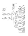
図1は、本発明の第1の実施の形態のネットワークシステムの構成を示すブロック図である。本実施の形態のネットワークシステムは、例えば、ルータ100A、100B、FW(FireWall)100C、100D、コアSW(SWitch)100E、100F、エッジSW100G、100H、100I、100J、物理サーバ200A、200B、200C、200D、仮想SW400A、400B、400C、400D、400E、仮想計算機(以下、VM:Virtual Machine)300A、300B、300C、300D、300E、300F、300G、300H、300I、300J、管理サーバ500、及び管理端末(運用者管理端末)700を備える。なお、以下の説明で、ルータ100A、100B、FW100C、100D、コアSW100E、100F、エッジSW100G、100H、100I、100J、を総称してNW(Network)装置100と説明する場合もある。
<First Embodiment>
FIG. 1 is a block diagram showing a configuration of a network system according to the first embodiment of this invention. The network system according to the present embodiment includes, for example,
さらに、以下の説明で、NW装置、物理サーバ200A、200B、200C、200Dを総称して物理装置または物理的な計算機資源と説明する場合もある。また、本実施形態では上記の種類の装置だけであるが、ロードバランサやVPN(Virtual Private Network)装置などでもよい。管理サーバ500は、NW装置、物理サーバ、仮想SW、及びVMを管理する計算機である。なお、仮想SWやVMは仮想的または論理的な計算機資源とする。管理サーバ500はNW装置と通信をすることができ、ネットワークシステムの構成情報の収集、NW装置、物理サーバ、仮想SW、及びVMの設定などを行うことができる。ルータ100A、100Bは、VPNやインターネットなどの外部ネットワーク2に接続している。ルータ100A、100Bから物理サーバ200または管理サーバ500までのネットワークがデータセンタ(Data Center:以下DC)内の内部ネットワークを構成する。なお、外部ネットワークは管理サーバ500の管理対象外である。図1では、管理サーバ500とNW装置100、物理サーバ200、仮想SW、及びVMは、論理的に分離されたネットワークで接続している。なお、物理的に別の管理用のネットワークで接続してもよい。管理サーバ500については、図2を用いて詳細に後述する。NW装置100、仮想SWは、ネットワーク内で通信される情報を、当該情報の宛先に転送する装置である。物理サーバ200は、仮想マシンVMを生成する仮想化部(図示省略)を実行し、仮想化部上で一つ以上の仮想マシンVMを稼動させる。また、仮想化部は内部に仮想SWを構成し、仮想SWを介して仮想化部上のVMと外部のネットワークを接続する。なお、仮想化部としてはハイパーバイザや、VMM(Virtual Machine Monitor)で構成することができる。
Furthermore, in the following description, NW devices and
管理端末700は、マウスやキーボードなどで構成された入力装置と、表示装置などで構成された出力装置を備えており、例えば、管理サーバ500に接続する。運用者(または管理者)は、管理端末700から管理サーバ500に各種指令を行うことができる。なお、NW装置100は、図示の例に限らず、適宜の数備えることができる。また、図1において、各装置を接続する枠内の数字は、各装置のポート番号を示す。
The
図2は、本実施の形態の管理サーバ500のブロック図である。管理サーバ500は、例えば、メモリ510、処理部(CPU)550、外部記憶部560、I/Oインターフェース(I/F)570及びネットワークインターフェース(I/F)580を備える。管理サーバ500は、内部ネットワークに接続される他の装置(例えば、NW装置100等)と、ネットワークI/F580を介して情報を送受信する。また、I/OI/F570は、例えば、HBA(Host Bus Adapter)等で構成され、図示しないストレージ装置などに接続することができる。
FIG. 2 is a block diagram of the
メモリ510は、例えば、自動設計プログラム511、自動設定プログラム512、NW(Net Work)装置情報収集プログラム513、接続情報生成プログラム514、テナントパターン情報(ノード)521、テナントパターン情報(サブネット)522、マッピング情報523、IDプール情報524、コマンドテンプレート情報525、テナントインスタンス情報(ノード)526、テナントインスタンス情報(サブネット)527、テナントインスタンス情報(マッピング)528、構成情報529、接続情報530、リング構成情報531、設計設定タスク情報532、スケジュール情報533を記憶する。なお、各プログラムはCPU550により実行されることができる。また、各プログラムは、非一時的な記憶媒体である外部記憶装置560等に格納され、CPU550がメモリ510にプログラムをロードして実行する。CPU550は、各機能部のプログラムに従って動作することによって、所定の機能を実現する機能部として動作する。例えば、CPU550は、自動設計プログラム511に従って動作することで自動設計部として機能する。他のプログラムについても同様である。さらに、CPU550は、各プログラムが実行する複数の処理のそれぞれを実現する機能部としても動作する。各機能を実現するプログラム、テーブル等の情報は、外部記憶装置560や不揮発性半導体メモリ、ハードディスクドライブ、SSD(Solid State Drive)等の記憶デバイス、または、ICカード、SDカード、DVD等の計算機読み取り可能な非一時的データ記憶媒体に格納することができる。
The
自動設計プログラム511は、管理端末700を利用する運用者(または管理者)からの要求に従い、テナントパターンに従ってネットワークシステムの設定内容を生成する。自動設定プログラム512は、自動設計プログラム512が生成した設定内容を元に、NW装置100、物理サーバ200に設定を反映させる。NW装置情報収集プログラム513は、NW装置100、物理サーバ200から、装置単位の接続情報、リング構成情報を収集する。接続情報生成プログラム514は、NW装置情報収集プログラムが収集した情報から、接続情報530を生成する。
The
テナントパターン情報(ノード)521は、テナントのノードの論理的な構成パターンを示し、テナントパターンに含まれるノードとそのノードのパラメータ、設定項目を管理する。すなわち、テナントパターン情報(ノード)521は、ノード毎のIP(Internet Protocol)構成を定義するもので、ノード毎の設定項目を有して、パラメータの決定方法と業務フローを管理する。テナントパターン情報(ノード)521は、管理端末700等から運用者が設定することができる。テナントパターン情報(ノード)521については、図4を用いて詳細を後述する。
Tenant pattern information (node) 521 indicates a logical configuration pattern of a tenant node, and manages the nodes included in the tenant pattern, parameters of the node, and setting items. That is, the tenant pattern information (node) 521 defines an IP (Internet Protocol) configuration for each node, and has setting items for each node, and manages a parameter determination method and a business flow. The tenant pattern information (node) 521 can be set by the operator from the
テナントパターン情報(サブネット)522は、テナントパターン毎のサブネットワーク(以下、サブネット)の構成パターンを示し、テナントパターンのサブネットの構成情報を管理する。すなわち、テナントパターン情報(サブネット)522は、サブネットの所属するノードなどの構成情報を管理するものである。テナントパターン情報(ノード)521は、管理端末700等から運用者が設定することができる。テナントパターン情報(サブネット)522については、図5を用いて詳細を後述する。
Tenant pattern information (subnet) 522 indicates a configuration pattern of a sub-network (hereinafter referred to as a subnet) for each tenant pattern, and manages configuration information of the subnet of the tenant pattern. That is, the tenant pattern information (subnet) 522 manages configuration information such as a node to which the subnet belongs. The tenant pattern information (node) 521 can be set by the operator from the
マッピング情報523は、テナントパターンのノードと当該ノードに対応する物理装置または仮想装置の関係を示すマッピングの種類を管理する。マッピング情報523は、管理端末700から運用者等が設定することができる。マッピング情報523については、図6を用いて詳細を後述する。
The
IDプール情報524は、ネットワークシステム内で割り当てるアドレスや識別子を含むIDプールの情報を管理する。IDプール情報524は、管理端末700等から運用者が設定することができる。なお、IDプール情報524については、図7を用いて詳細を後述する。
The
コマンドテンプレート情報525は、テナントパターン情報(ノード)521から参照されるコマンドの名称とコマンドテンプレート情報の対応関係を管理する。コマンドテンプレート情報525は、管理端末700等から運用者が設定することができるコマンドテンプレート情報525については、図8を用いて詳細を後述する。
The
テナントインスタンス情報(ノード)526は、自動設計プログラム511によって作成または更新されたノードに関するテナントインスタンスの情報を管理する。テナントインスタンス情報(ノード)526については、図9を用いて詳細を後述する。
The tenant instance information (node) 526 manages tenant instance information related to the node created or updated by the
テナントインスタンス情報(サブネット)527は、自動設計プログラム511によって作成または更新されたテナントインスタンスのうちサブネットの情報を管理する。テナントインスタンス情報(サブネット)527については、図10を用いて詳細を後述する。
Tenant instance information (subnet) 527 manages subnet information among tenant instances created or updated by the
テナントインスタンス情報(マッピング)528は、自動設計プログラム511によって作成または更新されテナントのインスタンスのうちノードと物理装置または仮想装置の対応関係を示すマッピング情報を管理する。テナントインスタンス情報(マッピング)528については、図11を用いて詳細を後述する。
Tenant instance information (mapping) 528 manages mapping information that is created or updated by the
構成情報529は、管理対象の物理装置または仮想装置毎にネットワーク装置情報収集プログラム513や自動設定プログラム512等が、情報を収集または設定するための認証情報やアドレス等を管理する。構成情報529については、図12を用いて詳細を後述する。
The configuration information 529 is managed by the network device
接続情報530は、接続情報生成プログラム514によって生成されて、物理装置間または仮想装置間の接続情報を管理する。接続情報530については、図13を用いて詳細を後述する。
The
リング構成情報531は、複数の物理装置上(または仮想装置上)に構成されているリングネットワークの構成情報を管理する。リング構成情報531は、NW装置情報収集プログラム513によって生成される。リング構成情報531については、図14を用いて詳細を後述する。設計設定タスク情報532は、運用者などが設計した設定内容を含む設計または設定タスクを管理する。設計設定タスク情報532については、図15を用いて詳細を後述する。スケジュール情報533は、設計または設定タスクの実行予定をスケジューリングする情報を管理する。スケジュール情報533については、図16を用いて詳細を後述する。
The
図3は、テナントパターン情報のイメージ図である。テナントパターン2000は、テナントの論理的なネットワークシステムの構成を規定する。つまり、図2に示したテナントパターン情報(ノード)521とテナントパターン情報(サブネット)522がテナントパターン2000を構成する。構成情報2200は、ネットワークシステム内の物理装置と仮想装置から収集した構成情報529と接続情報530である。マッピング情報2100は、テナントパターン2000の各ノードに対応する構成情報529を規定する。つまり、マッピング情報2100は、図2に示したマッピング情報523に対応する。
FIG. 3 is an image diagram of tenant pattern information. The
図1に示すネットワークシステムでは、複数のテナントが稼動しており、一つのテナント(契約者または利用者)は、図3で示すテナントパターン2000及びマッピング情報2100のように、他のテナントから論理的に分離されたネットワーク上の計算機資源を利用する。つまり、テナント毎にサブネットアドレスやVLAN(仮想ネットワーク) IDを設定して、論理的に分離した複数のネットワークシステムを顧客であるテナントに提供する。なお、VLANとしてはレイヤー2以上の層であればよい。
In the network system shown in FIG. 1, a plurality of tenants are operating, and one tenant (contractor or user) is logically transferred from other tenants like the
図3に記載のテナントパターン2000は、ルータ1、FW1、FW2、コアSW1、コアSW2、VM1、及びVM2のノードがあり、サブネット1〜4の4つのサブネットがあり、サブネット1にはルータ1、FW1、FW2が含まれ、サブネット2にはFW1、FW2、コアSW1、コアSW2が含まれ、サブネット3にはコアSW1、コアSW2、VM1が含まれ、サブネット4にはコアSW1、コアSW2、VM2が含まれる。このようにテナントパターン2000とマッピング情報2100を用いることで、論理的な構成でテナントを規定でき、全ての装置に対しての規定が不要になり、自動設計設定のための情報の作成、メンテナンスの作業が容易になる。という優れた効果を得ることができる。
The
マッピング情報2100について述べる。ルータ1は物理装置のルータ1、ルータ2に冗長化ありでマッピングされる。冗長化ありのマッピングの処理は、図24で詳細を後述する。図3において、FW1、FW2、コアSW1、コアSW2は、それぞれ物理装置のFW1、FW2、コアSW1、コアSW2にマッピングされる。VM1は、物理サーバ1と物理サーバ2からなるグループ1にマッピングされ、VM2は、物理サーバ3と物理サーバ4からなるグループ2にマッピングされる。各テナントインスタンスでVMがどの物理装置上のVMにマッピングされるかは、設計または設定時に決定する。このようにVMを物理サーバのグループにマッピングすることにより、1つのテナントパターン2000、マッピング情報2100で、異なる物理装置へのマッピングを規定することができる。これにより、テナントパターン2000、マッピング情報2100の数を減らすことが可能になり、テナントパターン(テナントパターン情報(ノード)521,テナントパターン情報(サブネット)522)の作成、更新などのメンテナンスに要する作業コストを削減できる。
The
なお、本実施形態ではひとつのテナントパターン2000を示すが、管理サーバ500は、複数のテナントパターンを格納する。これらのテナントパターンは、例えば、インターネット公開用の論理構成や、基幹業務用の論理構成など、論理構成の種別が異なるテナントパターンを複数用意するようにしてもよい。
In the present embodiment, one
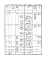
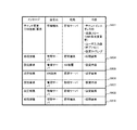
図4は、本実施の形態のテナントパターン情報(ノード)521の説明図である。テナントパターン情報(ノード)521は、例えば、パターンID5211、ノード5212、多重度(デフォルト値)5213、設定項目5214、パラメータ5215、パラメータ決定方法5216、業務フロー(操作種別)5217、及びコマンドテンプレート5218から一つのレコードが構成される。
FIG. 4 is an explanatory diagram of the tenant pattern information (node) 521 of the present embodiment. Tenant pattern information (node) 521 includes, for example,
テナントパターン情報(ノード)521では、テナントのノードとして、NW要素ではないが、テナントを管理するための情報(管理情報)を規定できる。また、テナントパターン情報(ノード)521では管理情報にパラメータを規定できる。管理情報には物理装置のマッピングを行わない。図4では、例えば、最終列の「管理情報」が上述したような管理情報である。 In the tenant pattern information (node) 521, information (management information) for managing a tenant can be defined as a tenant node, although it is not an NW element. In the tenant pattern information (node) 521, parameters can be defined in the management information. No physical device mapping is performed on management information. In FIG. 4, for example, the “management information” in the last column is the management information as described above.
テナントパターン情報(ノード)521のパターンID5211は、ネットワークシステム内でテナントパターンを一意に識別する情報である。ノード5212は、テナントパターンで規定するノードの情報である。多重度(デフォルト値)5213は、各テナントで同じ位置づけのノード(同じサブネットに属し、設定項目、パラメータが同じノード)をいくつ生成するかの情報である。多重度(デフォルト値)5213の値が、「−」の場合は当該ノードは1つとする。一方、多重度(デフォルト値)5213の値が、「*」の場合は、複数のノードを生成できる。また、ノード数はデフォルト値を規定できる。例えば、図4では、VM1はデフォルトで2ノードを生成する。運用者がノード数を指定した場合は、その数分のノードが生成される。運用者がノード数を指定しない場合は、デフォルト値5213で指定された数のノードを生成する。
The
設定項目5214は、ノードに対して設定される情報の種類を示す情報が格納される。パラメータ5215は、当該ノードのパラメータの項目を示す情報である。なお、パラメータはノード内の複数の設定項目で利用することが可能である。パラメータ決定方法5216は、ネットワーク構成の設計時にパラメータを決定する方法(または定義)が格納される。パラメータ決定方法5216の値は、例えば、「固定」、「プール」、「プール(サブネット指定)」、「参照」などがある。「固定」は、予め設定された固定の値であり、テナントパターン情報で規定する。
The
図4では、例えば、FW1のパラメータ「送信元」は、「Any」という固定値である。「プール」は、IDプール情報524で規定したIDプールを指定し、指定したIDプールから未使用のIDを割り当て、当該IDの値とする。なお、指定したIDプールから割り当てた値は指定したIDプールで「使用中」という状態に変更する。また、IDプールでは割り当て要求を受けた時に、どのIDを割り当てるかのロジックを予め指定する。この割り当てのロジックには、例えば、「若番から」(未使用の最小のIDから順に割り当てる)、「ランダム」(未使用のIDからランダムで割り当てる)などがある。図4では、例えば、FW1のパラメータ「ACL ID」の割り当てロジックは「若番から」である。したがって、このパラメータにはIDのプール6から未使用のIDのうち、最小の値のIDを割り当てる。図4では、例えば、FW1のパラメータ「ACL ID」は、プール6から値を割り当てる。「プール(サブネット指定)」は、指定したサブネットに割り当てられたネットワークアドレスから未使用のIPアドレスを割り当て、IDの値とする。なお、割り当てた値は指定したIDプールで「使用中」という状態に変更する。図4では、例えば、コアSW1のパラメータ「IPアドレス」は、サブネット3から値を割り当てて、IDプール3で状態を変更する。「参照」は他のノードのパラメータやサブネット情報、構成情報529の値を参照し、本パラメータの値とする。なお、参照先の値と同じ値とするだけでなく、参照先の値を元にして、予め設定した算術演算した値や、予め設定した文字列処理した値などを本パラメータとすることも可能である。
In FIG. 4, for example, the parameter “transmission source” of FW1 is a fixed value “Any”. “Pool” designates an ID pool defined by the
図4では、例えば、FW1のパラメータ「宛先」は、サブネット3のネットワークアドレスを参照し、参照した値をパラメータの値とする。業務フロー(操作種別)5217は、設定項目ごとに設計設定を実施する業務フローの情報と、その時の設定項目の操作種別である。操作種別は、「追加」、「変更」、「削除」があり、指定された操作種別に対応するコマンドテンプレートを使用し、設定内容を生成する。図4では、例えば、FW1の設定項目「ACL」は、業務フロー「ACL変更」、操作種別「追加」である。したがって、運用者が、業務フロー「ACL変更」を指定した場合、管理サーバ500は、FW1のACLの追加をし、追加用のコマンドテンプレートを用いて、設定内容を生成する。
In FIG. 4, for example, the parameter “destination” of FW1 refers to the network address of
1つの設定項目に対して、複数の業務フローを関連づけられる。このように、1つのテナントパターンを用いて、複数の業務フローを規定できるため、業務フロー毎に別の設定ファイルを作成する必要が無く、自動設計設定のための情報の作成、メンテナンスの作業が容易になる。 A plurality of business flows can be associated with one setting item. In this way, multiple business flows can be defined using one tenant pattern, so there is no need to create a separate setting file for each business flow, and the creation and maintenance of information for automatic design settings It becomes easy.
コマンドテンプレート5218は、設定内容のコマンドを生成するためのテンプレート情報である。追加、変更、削除用のコマンドテンプレートを登録する。
The
図5は、本実施の形態のテナントパターン情報(サブネット)522の説明図である。 FIG. 5 is an explanatory diagram of the tenant pattern information (subnet) 522 of the present embodiment.
テナントパターン情報(サブネット)522は、例えば、パターンID5221、サブネットID5222、VLAN利用5223、VLAN IDプール5224、所属ノード5225、及びアドレスプール5226を含む。
The tenant pattern information (subnet) 522 includes, for example, a
パターンID5221は、テナントパターンをネットワークシステム内で一意に識別する情報である。サブネットID5222は、テナントパターン内でサブネットを一意に識別する情報である。VLAN利用5223は、当該サブネットをVLANの利用で実現するか否かの情報である。VLAN利用5223が「○」の場合はVLANを構成する。一方、VLAN利用5223が「−」の場合はVLANを構成しない。
The
VLAN IDプール5224は、当該サブネットで利用するVLAN IDを割り当てるIDプールの情報である。所属ノード5225は、当該サブネットに所属するノードの情報である。アドレスプール5226は、当該サブネットで利用するネットワークアドレスを割り当てるIDプールの情報である。
The
以上のように、図4のテナントパターン情報(ノード)521と、図5のテナントパターン情報(サブネット)522で、テナントパターン毎に論理的な構成情報を定義しておき、ノード毎の設定項目と業務フロー(操作の種別)をテナントパターンの単位で管理する。前記従来例では、業務フロー毎にテンプレートが作成されていたのに対し、本発明では、ノード毎の設定項目をひとつのパターンで管理する点が特徴のひとつである。 As described above, the logical configuration information is defined for each tenant pattern in the tenant pattern information (node) 521 in FIG. 4 and the tenant pattern information (subnet) 522 in FIG. Manage business flows (operation types) in units of tenant patterns. In the conventional example, a template is created for each business flow. In contrast, the present invention is characterized in that setting items for each node are managed in one pattern.
図6は、本実施の形態のマッピング情報523の説明図である。
FIG. 6 is an explanatory diagram of the
マッピング情報523は、例えば、パターンID5231、ノード5232、物理装置/グループ5233、冗長化5234、デフォルトの仮想SW5235、ノード仮想化5236、及びグループからの選択方式5237を含む。
The
パターンID5231は、ネットワークシステム内でテナントパターンを一意に識別する情報である。ノード5232は、ネットワークシステム内でノードを一意に識別する情報である。物理装置/グループ5233は、ノードに割りあてられた物理装置(構成要素)の情報である。なお、図示の例では、
また、物理装置のグループへのマッピングをする場合は、本情報でグループを規定する。図6では例えば、ノード「VM1」は、物理サーバ1、物理サーバ2から構成されるグループ1にマッピングされる。冗長化5234は、テナントパターンのノードが冗長化されるか否かの情報である。冗長化5234が「○」であれば、冗長化を実施することを示す。図6では、ルータ1のノードは、2つの物理装置であるルータ1とルータ2で構成されて、冗長化を実現している例を示す。一方、冗長化5234が「−」であれば、冗長化を適用しない。
The
Also, when mapping physical devices to groups, this information defines the groups. In FIG. 6, for example, the node “VM1” is mapped to the
デフォルトの物理装置/仮想SW5235は、グループにマッピングされていて、グループからの選択方式が「ユーザ指定」の場合、デフォルトの物理装置を指定するための情報である。なお、ノード5232がVMの場合は、デフォルトの物理装置/仮想SW5235はVMを接続する仮想SWを選択する。これはネットワーク設計時には実体のVMがまだ配備されていない可能性があるためである。これにより、物理サーバ200上の仮想化部が生成した仮想SWをデフォルトの物理装置/仮想SW5235として設定することができる。
The default physical device /
ノード仮想化5236は、ノードを仮想化するか否かの情報である。サーバの場合は、物理サーバにマッピングする場合とVMにマッピングする場合があり、「ノード仮想化」が「○」の場合は、VMとして扱う。グループからの選択方式5237は、グループから物理装置を選択する方法である。選択方式5237は例えば、「ユーザ指定」、「VM数最小」などがある。「ユーザ指定」は、設計時にユーザが入力した物理装置(仮想SW)をマッピング先とする。「VM数最小」は、グループ内の物複数の理サーバのうち、既に配備されているVM数が最小の物理サーバ200を当該ノードのマッピング(割り当て)先として選択する。なお、選択方式は他の方式でもよい。
The
以上のように、マッピング情報523は、テナントパターン情報(ノード)521とテナントパターン情報(サブネット)522から実際に物理装置を割り当てる際に、仮想化や冗長化の有無や、ノードの多重度や、物理装置をどのグループ(またはリソースプール)から選択するかを定義することができる。
As described above, the
図7は、本実施の形態のIDプール情報524の説明図である。IDプール情報524は、例えば、ID5241、プール名5242、種類5243、最小ID5244、最大ID5245、ネットワークアドレス5246、及びデフォルトマスク長5247を含む。
FIG. 7 is an explanatory diagram of the
IDプール情報524は、ネットワークシステム全体で規定したアドレスや識別子を含み、複数のテナントパターンが共通で利用する。ID5241は、IDプールを一意に識別する識別子の情報である。プール名5242は、当該IDに対応するプールの名前情報である。種類5243は、IDプールの種類の情報である。種類は、例えば、「IPアドレス」、「ID」がある。「IPアドレス」では、ネットワークアドレス単位と個々のIPアドレス単位での2段階のID管理(使用、不使用の状態管理)を行う。「ID」では、個々のID単位でID管理(使用、不使用の状態管理)を行う。
The
最小ID5244は、プール内の最小のIDの値を示す。最大ID5245は、プール内の最大のIDの値を示す。
The
ネットワークアドレス5246は、プールに割り当てられるネットワークアドレスである。デフォルトマスク長5247は、ネットワークアドレスを割り当てる時のデフォルトのサブネットマスク長である。図7では、プール1から最初に割り当てられるネットワークアドレスは、10.0.0.0/26である。
The
なお、IDまたはネットワークアドレスの使用中、未使用の管理は、各ID5241のIDまたはネットワークアドレスについてビットマップ(図示省略)を設定する。そして、管理サーバ500は、使用中のIDまたはネットワークアドレスに対応するビットを「1」に設定し、未使用または返却されたIDまたはネットワークアドレスに対応するビットを「0」に設定する。このようにIDやネットワークアドレスの付与と回収を管理し、既に使用しているIDやネットワークアドレスをパラメータとして使わないことで、パラメータの決定を自動化しつつ、常時適切な値を決めることができる。
Note that, during use of IDs or network addresses, unused management sets a bitmap (not shown) for each
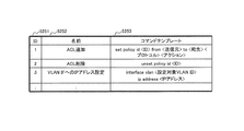
図8は、本実施の形態のコマンドテンプレート情報525の説明図である。
FIG. 8 is an explanatory diagram of the
コマンドテンプレート情報525は、例えば、ID5251、名前5252、及びコマンドテンプレート5253を含む。コマンドテンプレート情報525は、ネットワークシステム全体で規定し、複数のテナントパターンが共通で利用する。
The
ID5251は、ネットワークシステム内でコマンドテンプレートを一意に識別する情報である。名前5252は、コマンドテンプレートの名前情報である。コマンドテンプレート5253は、コマンドテンプレートを格納した情報である。コマンドテンプレートは、コマンド(または命令列)にパラメータを代入できるようになっており、管理サーバ500はコマンドテンプレート5253のコマンドにパラメータを代入することで、コマンドが完成する。図8の例では、例えば、ID5251=「2」の「ACL削除」のコマンドテンプレートは、「unset policy id <ID>」であり、<ID>にパラメータ「ID」を管理サーバ500が代入する。そして、管理サーバ500は、パラメータが設定されたコマンドテンプレート5253を実行する。
ID 5251 is information for uniquely identifying the command template in the network system. The name 5252 is name information of the command template. The
図9は、本実施の形態のテナントインスタンス情報(ノード)526の説明図である。 FIG. 9 is an explanatory diagram of the tenant instance information (node) 526 according to this embodiment.
テナントインスタンス情報(ノード)526は、例えば、テナントインスタンスID5261、ノード5262、ノードインスタンス5263、設定項目5264、パラメータ5265、及びパラメータ値5266を含む。
The tenant instance information (node) 526 includes, for example, a
テナントインスタンスID5261は、テナント毎のインスタンスをネットワークシステム内で一意に識別する情報である。ノード5262は、テナントパターンのノードである。ノードインスタンス5263は、テナントインスタンスのノードの情報である。冗長化されたノードや多重度が設定されたVMの場合は、1つのノードに対して、複数のノードインスタンスが生成される。図9では、例えば、ノード5262=「ルータ1」のノードインスタンス5263は「ルータ1−1」と「ルータ1−2」である。2つのノードインスタンスによって、ノード5262=「ルータ1」は冗長構成となっていることを示す。
The
設定項目5264は、各ノードインスタンスについて設定する項目が格納される。パラメータ5265は、設定項目5264に対するパラメータの種別が格納される。パラメータ値5266は、設計時に決定したパラメータの値が格納される。
The
図9では、ノード5262=「VM1」は、ユーザが多重度を「3」と設定したため、3つのノードインスタンス5263=「tVM1−1」、「tVM1−2」、「tVM1−3」が生成されている。一方、ノード「VM2」はデフォルトの多重度(図4の多重度5213)であり、1つのノードインスタンス5263「tVM2−1」が生成されている。
In FIG. 9, since the user sets the multiplicity to “3” for the
図10は、本実施の形態のテナントインスタンス情報(サブネット)527の説明図である。 FIG. 10 is an explanatory diagram of the tenant instance information (subnet) 527 of this embodiment.
テナントインスタンス情報(サブネット)527は、例えば、テナントインスタンスID5271、ID5272、VLAN ID5273、所属ノード5274、接続ノード5275、及びネットワークアドレス5276を含む。
The tenant instance information (subnet) 527 includes, for example, a
テナントインスタンスID5271は、テナント毎のインスタンスを一意に識別する情報である。ID5272は、テナントインスタンス内でサブネットを一意に識別する情報である。VLAN ID5273は、当該サブネットに割り当てられたVLAN IDである。所属ノード5274は、当該サブネットに所属するノード情報である。接続ノード5275は、所属ノード5274を接続するために選択したノードである。ネットワークアドレス5276は、当該サブネットに割り当てられたネットワークアドレスである。
The
図11は、本実施の形態のテナントインスタンス情報(マッピング)528の説明図である。テナントインスタンス情報(マッピング)528は、接続情報生成プログラム514及びNW装置情報収集プログラム513によって生成または更新される。
FIG. 11 is an explanatory diagram of tenant instance information (mapping) 528 according to the present embodiment. The tenant instance information (mapping) 528 is generated or updated by the connection information generation program 514 and the NW device
テナントインスタンス情報(マッピング)528は、例えば、テナントインスタンスID5281、ノード5282、及び対応装置5283を含む。
The tenant instance information (mapping) 528 includes, for example, a
テナントインスタンスID5281は、テナントインスタンスを一意に識別する情報である。
The
ノード5282は、テナントインスタンスのマッピング元のノード情報である。対応装置5283は、テナントインスタンスのマッピング先の装置情報である。なお、VMのマッピング先は、仮のVMに加え、当該VMが接続する仮想SWと当該仮想SWを含む物理サーバの情報を含む。これは、ネットワークの設計時はVMが物理サーバ200上にデプロイされていない場合があるためである。
The
図12は、本実施の形態の構成情報529の説明図である。 FIG. 12 is an explanatory diagram of the configuration information 529 of the present embodiment.
構成情報529は、例えば、装置5291、管理IPアドレス5292、Telnetアカウント5293、及びSNMPコミュニティ名5294を含む。
The configuration information 529 includes, for example, a
装置5291は、装置をネットワークシステム内で一意に識別する情報である。管理IPアドレス5292は、当該装置から情報を収集したり、設定したりするためのアクセス先の管理用IPアドレス情報である。Telnetアカウント5293は、当該装置に設定をする時に使用する認証情報であるTelnetアカウントとパスワードである。なお、Telnetではなく、SSHなどで物理装置にアクセスをしてもよく、その場合は、SSHのアカウント情報を持つ。SNMPコミュニティ名5294は、当該装置からSNMPで情報を収集する時に使用するSNMPコミュニティ情報である。
The
図13は、本実施の形態の接続情報530の説明図である。
FIG. 13 is an explanatory diagram of the
接続情報530は、例えば、リンクID5301、接続装置1 5302、装置1 ポートID5303、接続装置2 5304、及び装置2 ポートID5305を含む。
The
リンクID5301は、物理装置間または仮想装置間のリンクをネットワークシステム内で一意に識別する情報である。接続装置1(5302)は、リンクに接続している一方の物理装置または仮想装置を一意に識別する情報である。装置1ポートID5303は、リンクに接続している一方の物理装置のポートを一意に識別する情報である。接続装置2(5304)は、リンクに接続している他方の物理装置または仮想装置を一意に識別する情報である。装置2ポートID5305は、リンクに接続している他方の物理装置のポートを一意に識別する情報である。接続情報530は、一つのリンクの始点と終点の装置が接続されるポートIDを特定することができる。
The
図14は、本実施の形態のリング構成情報(冗長化ネットワーク情報)531の説明図である。 FIG. 14 is an explanatory diagram of the ring configuration information (redundant network information) 531 according to this embodiment.
リング構成情報531は、例えば、リングID5311、構成装置5312、マスタノード5313、フォワーディングポートID5314、及びブロッキングポートID5315を含む。
The
リングID5311は、リングネットワークをネットワークシステム内で一意に識別する情報である。構成装置5312は、当該リングネットワークに所属している全ての物理装置一覧の情報である。マスタノード5313は、当該リングネットワークのマスタノードの装置の情報である。フォワーディングポートID5314は、マスタノードのフォワーディングポートの情報である。なお、リングネットワークのフォワーディングポートは、定常時にパケットを転送するポートである。ブロッキングポートID5315は、マスタノードのブロッキングポートの情報である。なお、リングネットワークのブロッキングポートは、定常時にパケット転送をせず、障害検知時にパケットを転送するようになるポートである。
The
なお、上記では冗長化ネットワークの一例としてリングネットワークを構成する例を示したが、スパニングツリーなど公知又は周知のその他の冗長化ネットワークを適用するようにしても良い。 In addition, although the example which comprises a ring network as an example of a redundant network was shown above, you may make it apply other well-known or well-known redundant networks, such as a spanning tree.
図15は、本実施の形態の設計設定タスク情報532の説明図である。
FIG. 15 is an explanatory diagram of the design
設計設定タスク情報532は、例えば、ID5321、設計日時5322、設定完了日時5323、設計内容5324、使用パターン5325、テナントインスタンス5326、設定内容5327、及び状態5328を含む。
The design
ID5321は、設計設定タスクを一意に識別する情報である。設計日時5322は、当該設計設定タスクの設計が完了した日時である。設定完了日時5323は、当該設計設定タスクの設定が完了した日時である。設計内容5324は、当該設計設定タスクの設計内容である。使用パターン5325は、当該設計設定タスクが使用したテナントパターンである。テナントインスタンス5326は、当該設計設定タスクで生成したテナントインスタンスを一意に識別する情報である。設定内容5327は、当該設計設定タスクが生成した設定内容である。
The ID 5321 is information for uniquely identifying the design setting task. The design date and time 5322 is the date and time when the design of the design setting task is completed. The setting completion date and
図15では設計設定タスク情報532を、自然言語で記載しているが、合わせて、設定用コマンドも保持する。状態5328は、当該設計設定タスクの状態情報である。例えば、「設計済み」であれば設計が完了し、実機への設定は未実施であることを示し、「設定済み」であれば、実機への設定が完了したことを示し、「設定失敗」であれば、実機への設定が失敗したことを示す。
In FIG. 15, the design
図16は、本実施の形態のスケジュール情報533の説明図である。
FIG. 16 is an explanatory diagram of the
スケジュール情報533は、例えば、ID5331、設定予定日時5332、タスクID5333、及び状態5334を含む。スケジュール情報533は、運用者が設計時に設定実施時刻をスケジューリングした場合に生成される。
The
ID5331は、当該スケジュール情報を一意に識別する情報である。設定予定日時5332は、設計設定タスクを実施する予定の日時の情報である。タスクID5333は、当該スケジュールで実行する設計設定タスクを一意に識別する情報である。状態5334は、当該スケジュールの実施状態である。例えば、「未実施」であれば、設定予定日時前で設定が実施される前の状態を示し、「実施済み」であれば、設定予定日時後で設定が実施された状態を示す。
The
図17は、管理端末700を利用する運用者がテナントを追加するネットワークの設計または設定を実施するユーザインタフェース170の説明図である。このユーザインターフェース170は、管理端末700の出力装置に表示された画面イメージである。
FIG. 17 is an explanatory diagram of a
運用者はユーザインターフェース170で追加したいテナントのパターンをプルダウン171から選択する。また、設定を実施するタイミングを、「即時設定実行」か「設定スケジューリング」から選択する。「設定スケジューリング」を選択した場合は、設定実行する日時172を入力する。特別な要件がない場合は、運用者が入力する情報は上記項目でよく、運用者はネットワークに関する詳細な内容を考慮することなく、設計及び設定が行える。このように、ネットワークに詳しくない運用者であっても間違えることなく、ネットワークの設計、設定を実施することができる。
The operator selects from the pull-down 171 the tenant pattern to be added on the
また、テナントパターン171で、「ユーザ指定」と規定されたパラメータ173やマッピング175は「ユーザ指定(オプション)」以下に入力フィールドが表示される。「マッピング」の入力フィールド175には、マッピング情報523の物理装置/グループ5233でグループを規定した項目が表示される。
In addition, in the
図17では、ノード「VM1−1」の対応装置として「仮想SW1−1」が表示されている。ノードがVMの場合は、このように仮想SWを選択する。一方、ノードがVM以外の場合は、直接対応する装置(FWであればFWなど)が選択肢として表示される。 In FIG. 17, “virtual SW1-1” is displayed as the corresponding device of the node “VM1-1”. When the node is a VM, the virtual SW is selected in this way. On the other hand, if the node is other than VM, a directly corresponding device (such as FW if FW) is displayed as an option.
図18は、管理端末700を利用するネットワーク設計者がテナントパターンを規定するユーザインタフェース180の画面イメージである。
FIG. 18 is a screen image of the
本ユーザインタフェース180は、通常ネットワークスキルが低い運用者ではなく、ネットワークの設計ができる設計者が、本システム導入時や、物理構成や業務フローの変更時に利用する。
This
本ユーザインタフェース180は、大きく3つの部分からなる。「テナントパターン規定」181、「業務フロー規定」182、「IDプール規定」183、である。「テナントパターン規定」181の領域には、テナントパターン一覧1811があり、テナントパターンの追加、変更、削除ができるボタンが表示される。入力装置の操作により追加ボタンを押下すると、テナントパターン情報入力フィールド1812で入力を受け付ける。当該フィールド1812へテナントパターンIDやサブネットの情報を入力し、確定ボタンを押下すると、テナントパターンが追加される。サブネット一覧の追加、変更ボタン1813を押すと、図19のパターン登録(サブネット編集)画面に遷移する。サブネット編集画面については図19にて後述する。
The
「業務フロー規定」182の領域には、業務フロー一覧が表示される。「業務フロー規定」182の領域で登録した業務フローを図19の設定項目編集の業務フローのプルダウンで選択できる。追加ボタン1821を押下すると一覧にエントリが追加され、一覧上で業務フロー名を編集できる。削除ボタンを押下すると、一覧で選択していた業務フローが削除される。また、変更は一覧上で編集することで実施する。
A list of business flows is displayed in the area of “business flow rules” 182. The business flow registered in the area of “business flow rule” 182 can be selected from the pull-down menu of the business flow for setting item editing in FIG. When an
「IDプール規定」183の領域には、IDプール一覧がある。追加ボタン1831を押下すると一覧にエントリが追加され、一覧上でIDプール情報を編集できる。削除ボタンを押下すると、一覧で選択していたIDプールが削除される。また、変更は一覧上で編集することで実施する。
In the area of “ID pool rules” 183, there is an ID pool list. When an
本画面で入力した内容は、IDプール情報524に格納される。
The content entered on this screen is stored in the
図19は、管理端末700を利用するネットワーク設計者がテナントパターンのサブネットを規定するユーザインタフェース190の画面イメージである。サブネットID191や当該サブネットで使用するIDプールの入力フィールド192などが表示される。サブネットに所属するノード一覧193が表示され、追加ボタン195を押下すると、ノード編集領域194に入力できるようになり、ノード名や設定項目、パラメータ、マッピングなどを入力し、確定ボタンを押下すると、ノード情報を追加することができる。
FIG. 19 is a screen image of the
変更ボタン196を押下すると、一覧193で選択していたノードの情報が、ノード編集領域194に表示され、その値を編集できるようになる。編集後、確定ボタン198を押下すると、ノード情報が変更される。削除ボタン197を押下すると、一覧193で選択していたノードが削除される。ノード編集フィールドの、設定項目、パラメータについても同様に追加、変更、削除が可能である。
When the
本画面で入力した内容は、テナントパターン情報(ノード)521、テナントパターン情報(サブネット)522、マッピング情報523、コマンドテンプレート情報525に格納される。
The contents input on this screen are stored in tenant pattern information (node) 521, tenant pattern information (subnet) 522, mapping
図20は、本実施の形態の管理サーバ500の初期導入時のシーケンス図である。図21は、本実施の形態の管理サーバ初期導入時において送受信されるメッセージの一例を説明する図である。
FIG. 20 is a sequence diagram at the time of initial introduction of the
図20において、まず、管理端末700は、管理サーバ500に構成情報収集を要求する(S101)。管理サーバ500は要求を受け付けると、要求に含まれている収集対象装置であるNW装置100、物理サーバ200に対して、構成情報を要求する(S102、S104)。
In FIG. 20, first, the
NW装置100は要求を受け付けると、自身が持っている隣接装置との接続情報と、リングが構成されている場合は、リング構成情報を管理サーバ500に送信する(S103)。物理サーバ200は要求を受け付けると、自身が持っている仮想SW一覧と、VM一覧、および接続情報を管理サーバ500に送信する(S105)。
When the
管理サーバ500は、NW装置100、物理サーバ200から送信された接続情報から物理装置間または仮想装置間の接続情報を生成し、接続情報530に格納する(S106)。なお、物理装置と仮想装置の接続は、例えば、エッジスイッチ100Gと仮想スイッチ400Aの接続などである。管理サーバ500は、管理端末700に構成情報収集が成功したか、接続情報生成が成功したかなどの処理結果を通知する(S107)。
The
管理端末700は、図18、図19に示したユーザインターフェース180、190から入力されたテナントパターン規定情報を管理サーバ500に送信する(S108)。
The
管理サーバ500は、受信したテナントパターン規定情報を、テナントパターン情報(ノード)521、テナントパターン情報(サブネット)522、マッピング情報523、IDプール情報524、コマンドテンプレート情報525に、それぞれ格納する(S109)。管理サーバ500は、テナントパターン規定情報の格納が成功したか否かを示す処理結果を管理端末700に通知する(S110)。
The
上記処理によって、ネットワークシステムへ新たに導入した管理サーバ500は、接続情報530と、テナントパターン情報(ノード)521と、テナントパターン情報(サブネット)522と、マッピング情報523と、IDプール情報524と、コマンドテンプレート情報525とを生成してメモリ510及び外部記憶装置560へ格納する。
The
なお、上記図20では、管理端末700のユーザインターフェースを用いて、テナントパターン規定情報を入力しているが、テナントパターン規定情報を予め設定ファイルとして作成し、管理サーバ500で読み込むようにしてもよい。
In FIG. 20, the tenant pattern definition information is input using the user interface of the
また、図21に示すメッセージは、上記図20の各ステップS101〜S110で、送受信されるメッセージと送信元、送信先及び内容をそれぞれ示す。 Further, the message shown in FIG. 21 indicates the message to be transmitted / received in each step S101 to S110 in FIG.
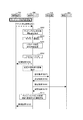
図22は、本実施の形態の運用中におけるテナントを追加する例のネットワーク設計設定時のシーケンス図である。 FIG. 22 is a sequence diagram at the time of network design setting of an example of adding a tenant during operation of the present embodiment.
図23は、本実施の形態のネットワークの設計及び設定時において送受信されるメッセージの一例を示す図である。 FIG. 23 is a diagram illustrating an example of messages transmitted and received when designing and setting the network according to the present embodiment.
図22において、まず、管理端末700は管理サーバ500にテナント追加を要求する(S201)。要求には使用するテナントパターン(テナントパターン情報(ノード)521及びテナントパターン情報(サブネット)522のパターンID5211、5221)のIDと、運用者が指定した場合はユーザ入力値と、設定タイミング(即時実行するのか、スケジューリングするのか)が含まれる。以下、テナントパターン情報(ノード)521及びテナントパターン情報(サブネット)522の総称をテナントパターンとする。
In FIG. 22, first, the
管理サーバ500は、マッピング情報523からテナントパターンに対応する対応装置を特定する(S202)。本処理は、図24を用いて詳細を後述する。管理サーバ500は、特定した装置情報を用いて、サブネットを具現化するための設定内容を生成する(S203)。本処理は、図25を用いて詳細を後述する。
The
管理サーバ500は、テナントを追加する際のネットワークシステムのノードに対するパラメータを決定し、設定内容を生成する(S204)。本処理は、図26を用いて詳細を後述する。上記設定タイミングで「スケジューリング」が指定されている場合は、物理装置(または仮想装置)への設定の実行予定をスケジューリングする(S205)。管理サーバ500は、設計処理と、スケジューリング処理が成功したか否かを示す処理結果を管理端末700に通知する(S206)。
The
管理サーバ500は、スケジューリングで指定された時刻になったら、設定処理を開始し、NW装置100、物理サーバ200に設定を要求する(S207、S209)。NW装置100、物理サーバ200は要求を受信したら、ステップS203、S204で生成した設定内容に従い、自身の構成情報を更新し、管理サーバ500に設定結果を通知する(S208、S210)。管理サーバ500は、追加したテナントのテナントインスタンスを作成し、テナントインスタンス情報(ノード)526、テナントインスタンス情報(サブネット)527、テナントインスタンス情報(マッピング)528に格納する。そして、管理サーバ500は設計設定タスク情報532の状態を更新する(S211)。管理サーバ500は、管理端末700に処理結果を通知する(S212)。
The
上記処理によって、スケジュールに対応するタイミングで、管理端末700から入力されたテナントパターンのIDに基づいて、管理サーバ500は、ネットワークシステム内に新たなテナントを追加する。このとき、管理端末700の運用者は、テナントパターンのIDと業務フロー(追加)を指定するだけで、管理サーバ500の自動設計プログラム511がネットワーク構成や物理サーバなどの物理装置の設定を自動的に計算することができる。これにより、ネットワークに精通していない運用者でも、新たなテナントを追加する際の設定を容易に取得できる。そして、指定されたスケジュールで自動設定プログラム512が、新たなテナントの設定を物理装置や仮想装置に反映させることで、新たなテナントがネットワークシステム内に追加される。
Based on the tenant pattern ID input from the
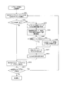
図24は、本実施の形態の対応装置特定処理のフローチャートである。このフローチャートは、上記図22のステップS202で行われるマッピング情報523から対応装置を特定する処理の一例を示す。
FIG. 24 is a flowchart of the corresponding device specifying process according to this embodiment. This flowchart shows an example of processing for identifying a corresponding device from the
管理サーバ500は、テナントパターン情報(ノード)521を参照し、管理端末700から指定されたテナントパターンのノードのうち未処理のノードを選択する(S301)。
The
管理サーバ500は、マッピング情報523の冗長化5234を参照し、選択したノードのマッピングが「冗長化」ありか否かを判定する(S302)。冗長化ありの場合は、マッピング先の複数の物理装置(または仮想装置)を対応装置として、冗長構成となる設定内容を生成する(S303)。
The
例えば、図6では、ノード「ルータ1」が冗長化ありを示す。ルータに対しての冗長化方式はVRRP(Virtual Router Redundancy Protocol)があり、対応装置(ルータ1、ルータ2)にVRRPの冗長化の設定を生成する。具体的には、図9に示すノード5262のルータ1に記載のVRRPの設定である。ここでは冗長化方式をVRRPとしたが、その他の冗長化方式でもよい。また、ルータや、スイッチだけでなく、FWなどのアプライアンスについても冗長化に対応した設定内容の生成も可能とする。その後、図24のステップS310に進む。
For example, in FIG. 6, the node “
冗長化なしの場合は、管理サーバ500は、マッピング情報523の「物理装置/グループ」5233を参照し、グループへのマッピングであるか否を判定する(S304)。
When there is no redundancy, the
グループへのマッピングの場合は、管理サーバ500は、グループ内から「グループからの選択方式」5237で規定された選択方式に従い、仮の対応装置を選択する(S305)。グループへのマッピングではない場合は、マッピング先の物理装置または仮想装置を仮の対応装置として選択する(S306)。
In the case of mapping to a group, the
次に、管理サーバ500は、現在選択しているノードがVMであるか否かを判定する(S307)。VMの場合は、仮の対応装置のデフォルトの仮想SW、またはユーザが指定した仮想SWに接続する仮のVMを管理サーバ500が生成して対応装置とする(S308)。これは、ネットワークの設計時点ではVMが配備されていない可能性があるため、配備予定のVMが接続される仮想SWを代わりに選択しておく。ネットワークの設定としては、仮想SWまで設定できれば十分である。
Next, the
現在選択しているノードがVMではない場合、管理サーバ500は仮の対応装置を対応装置として選択する(S309)。次に、管理サーバ500は未処理のノードがあるか否かを判定する(S310)。未処理のノードがある場合は、S301に戻る。未処理のノードがない場合は、処理を終了する。
If the currently selected node is not a VM, the
このようにして、管理サーバ500では、新たなテナントを追加する際のネットワーク構成の設計時に具体的に対応する物理装置や仮想装置を決定することができる。このため、テナントパターンの規定時点で複数の対応関係を1つのマッピングで規定できる。したがって、マッピングの規定や、メンテナンスを容易に行える。
In this way, the
図25は、本実施の形態のサブネット具現化処理のフローチャートである。このフローチャートは、上記図22のステップS203で行われるサブネットの具現化処理の一例を示す。 FIG. 25 is a flowchart of subnet realization processing according to the present embodiment. This flowchart shows an example of subnet realization processing performed in step S203 of FIG.
管理サーバ500は、図5に示したテナントパターン情報(サブネット)522を参照し、指定されたテナントの未処理のサブネットを選択する(S401)。管理サーバ500は、図5に示したVLAN利用5223を参照し、選択したサブネットが「VLAN利用」ありか否かを判定する(S402)。「VLAN利用」なしの場合、処理S409に進む。「VLAN利用」ありの場合、管理サーバ500は、図24に記載の対応装置特定処理で特定したサブネットに所属するノードの対応装置を選択する(S403)。
The
管理サーバ500は、接続情報530を参照し、選択した対応装置を接続する経路を算出する(S404)。経路算出のアルゴリズムは、例えば、ダイクストラ法など公知又は周知の手法を用いることができる。次に、管理サーバ500はリング構成情報531を参照し、算出した経路上にリングネットワークが構成されているか否かを判定する(S405)。リングネットワークが構成されている場合、管理サーバ500は当該VLANをリングネットワークに所属させる設定内容を生成する(S406)。その後、処理S407に進む。リングネットワークが構成されていない場合、管理サーバ500は指定されたIDプールからVLAN IDを割り当てる(S407)。割り当てたVLAN IDのVLANを対応装置に割り当てる設定内容を生成する(S408)。
The
次に、管理サーバ500は、現在選択しているサブネットに対して、指定されたIDプールからネットワークアドレスを割り当てる(S409)。次に、管理サーバ500は、未処理のサブネットがあるか否かを判定する(S410)。未処理のサブネットがある場合、処理S401に戻る。未処理のサブネットがない場合、処理を終了する。
Next, the
このように論理的な構成として規定したサブネットに所属する装置を算出し、サブネットを実現するVLANを自動的に設定内容を生成できるため、テナントパターンを論理的な構成で規定することができ、テナントを追加する際のネットワーク構成の作成や、ネットワークシステムのメンテナンスを容易に行える。 As described above, since the devices belonging to the subnet defined as the logical configuration can be calculated and the setting contents of the VLAN that realizes the subnet can be automatically generated, the tenant pattern can be defined by the logical configuration. Creating a network configuration and adding network systems can be done easily.
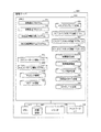
図26は、本実施の形態のパラメータ決定、設定内容生成処理のフローチャートである。このフローチャートは、上記図22のステップS204で行われるパラメータの決定と、設定内容を生成する処理の一例を示す。 FIG. 26 is a flowchart of parameter determination and setting content generation processing according to the present embodiment. This flowchart shows an example of the parameter determination and setting content generation processing performed in step S204 of FIG.
管理サーバ500は、図4に示したテナントパターン情報(ノード)521を参照し、テナントパターンの未処理のパラメータを選択する(S501)。管理サーバ500は、テナントパターン情報(ノード)521のパラメータ決定方法5216の種類により、パラメータを決定する方法を「固定」、「プール」、「プール(サブネット指定)」、「参照」の何れかひとつを選択する(S502)。パラメータ決定方法が「固定」の場合、所定の固定値をパラメータの値とする(S503)。パラメータ決定方法が「プール」の場合、指定されたプールから値を割り当てる。その際、パラメータ決定方法5216で規定された割り当てロジック(「若番から」など)に従って、割り当てる(S504)。パラメータ決定方法が「プール(サブネット指定)」の場合、図25のステップS409で決定したネットワークアドレスから未使用のIPアドレスを割り当、指定されたサブネットの値とする。(S505)。パラメータ決定方法が「参照」の場合、管理サーバ500は、参照先の値が未決定か否かを判定する(S506)。参照先の値が未決定の場合、当該パラメータの処理順番を最後にし(S507)、処理S501に戻る。一方、参照先の値が決定済みの場合、管理サーバ500は参照先の値を用いて、本パラメータの値とする(S508)。本パラメータの値を決定した後、管理サーバ500は未処理のパラメータがあるか否かを判定する(S509)。未処理のパラメータがある場合、処理S501に戻る。未処理のパラメータない場合、追加のコマンドテンプレートにパラメータを代入し、設定内容を生成する(S510)。
The
以上のように、図22で示したステップS201〜S206を、管理サーバ500の自動設計プログラム511で処理し、ステップS207〜S212を管理サーバ500の自動設定プログラム512で処理することで、テナントの追加にかかるネットワークの設計と設定を自動的に行うことができる。これにより、前記従来例のように多数のテンプレートを作成する必要はなく、テナントパターンの単位で、ネットワーク管理システムの初期設定や、ネットワークシステムのメンテナンスを容易にすることができ、特に、日々の運用者がネットワークに対するスキルがなくてもネットワークの設計または設定を容易に行うことが可能になる。
As described above, steps S201 to S206 shown in FIG. 22 are processed by the
そして、上述のように、業務フローが「追加」の場合では、管理サーバ500はテナントパターンを受け付けると、マッピング情報523に従って物理装置を選択する。そして、管理サーバ500は、テナントパターン情報(サブネット)522からサブネットを生成してIP構成を決定する。そして、管理サーバ500は、テナントパターン情報(ノード)521の設定項目についてパラメータを予め設定された方法で決定し、コマンドテンプレート5253にパラメータを代入して設定内容を生成する。そして、スケジュールで指定された所定のタイミングになると、管理サーバ500の自動設定プログラム512は、設定内容を実行してテナントに物理装置や仮想装置を割り当てて、稼動を開始する。
As described above, when the business flow is “addition”, the
こうして、複数の物理サーバを備えたネットワークシステムへ極めて容易に新たなテナントを極めて容易に追加することができる。これにより、プライベートクラウドなどの計算機リソースをオンデマンドで提供するデータセンタにおいて、テナントを追加する際に運用者の労力を大幅に低減することができる。 In this way, a new tenant can be added very easily to a network system having a plurality of physical servers. Thereby, in a data center that provides computer resources such as a private cloud on demand, the labor of an operator can be significantly reduced when a tenant is added.
なお、図4のテナントパターン情報(ノード)521では、パラメータの一例について述べたが、パラメータの設定は図4に限定されるものではなく、例えば、パラメータの項目を大分類と小分類に分けても良い。図30に、パラメータの項目を大分類と小分類に分けた例を示す。図30の例では、ルータ又はスイッチのノードについて、パラメータの大分類として、経路情報、VRRP、VRF(Virtual Routing and Forwarding)、ゲートウェイ設定、ゾーニングなどで構成される例を示した。また、大分類に従属する小分類には、宛先、アドレス、ゾーン名やIDなどで構成された例を示す。このように、テナントパターン情報(ノード)521のパラメータとしては、図4で開示した項目に加え、図30で開示した項目を含めるようにしても良い。 In the tenant pattern information (node) 521 in FIG. 4, an example of the parameter has been described. However, the parameter setting is not limited to FIG. 4. For example, the parameter items are divided into a large classification and a small classification. Also good. FIG. 30 shows an example in which parameter items are divided into a large classification and a small classification. In the example of FIG. 30, an example is shown in which a router or a switch node is configured by route information, VRRP, VRF (Virtual Routing and Forwarding), gateway setting, zoning, and the like as major classifications of parameters. In addition, an example including a destination, an address, a zone name, an ID, and the like is shown in the minor classification subordinate to the major classification. As described above, the parameters disclosed in FIG. 30 may be included as parameters of the tenant pattern information (node) 521 in addition to the items disclosed in FIG.
<第二の実施の形態>
第二の実施の形態について、説明する。第二の実施の形態は、すでに設計及び設定済みのテナントインスタンスを変更する設計及び設定を実行する実施形態である。以下では、VMを追加する場合について述べるが、ACL追加、VLAN追加などの他の変更や、テナントインスタンスを削除する場合でも同様の処理となる。
<Second Embodiment>
A second embodiment will be described. The second embodiment is an embodiment for executing design and setting for changing a tenant instance that has already been designed and set. In the following, the case of adding a VM will be described, but the same processing is performed even when other changes such as ACL addition, VLAN addition, etc., or when a tenant instance is deleted.
このようにテナントインスタンスを変更、削除する場合でも新規追加の場合と同じテナントパターンの規定とマッピング情報を使用でき、新規追加や変更、削除毎に別の設定が不要であり、自動設計設定のための情報の作成や、メンテナンスの作業が容易になる。 In this way, even when a tenant instance is changed or deleted, the same tenant pattern rules and mapping information as in the case of new addition can be used, and there is no need for separate settings for each new addition, change, or deletion. This makes it easy to create and maintain information.
図27は、本実施の形態の運用中での既存のテナントを変更(VMを追加)するネットワーク設計及び設定時のシーケンス図である。 FIG. 27 is a sequence diagram at the time of network design and setting for changing an existing tenant during operation of this embodiment (adding a VM).
図28は、本実施の形態のネットワーク設計設定時において送受信されるメッセージを説明する図である。 FIG. 28 is a diagram for explaining messages transmitted and received at the time of network design setting according to the present embodiment.
図27において、まず、管理端末700は管理サーバ500にテナント変更を要求する(S601)。要求には変更するテナントインスタンスのID、変更内容を示す業務フロー、運用者が指定した場合はユーザ入力値、設定タイミング(即時実行するのか、スケジューリングするのか)が含まれる。
In FIG. 27, first, the
管理サーバ500は、業務フローに従ったテナント変更処理を行う(S602)。本処理は、図29を用いて詳細を後述する。設定タイミングで「スケジューリング」が指定されている場合は、物理装置または仮想装置への設定をスケジューリングする(S603)。管理サーバ500は、設計処理、スケジューリング処理が成功したか否かを管理端末700に通知する(S604)。
The
管理サーバ500は、スケジューリングで指定された時刻になったら、自動設定プログラム512を起動して設定処理を開始し、NW装置100、物理サーバ200に設定を要求する(S605、S607)。NW装置100、物理サーバ200は設定要求を受信したら、設定内容に従い、自身の構成情報を更新し、管理サーバ500に設定結果を通知する(S606、S608)。
When the time specified by the scheduling is reached, the
管理サーバ500は、変更したテナントインスタンスを設計内容に従い更新し、テナントインスタンス情報(ノード)526、テナントインスタンス情報(マッピング)528に格納する。そして、設計設定タスク情報532の状態を更新する(S609)。管理サーバ500は、管理端末700に処理結果を通知する(S610)。
The
以上の処理により、管理サーバ500はテナントの変更要求を受け付けると、変更要求に応じてNW装置100、物理サーバ200の構成を業務フローに従って自動的に変更することができる。
Through the above processing, when the
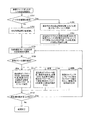
図29は、本実施の形態の業務フローに従ったテナント変更処理のフローチャートである。この処理は図28のステップS602で行われる業務フローに従ったテナント変更処理の一例を示す。 FIG. 29 is a flowchart of tenant change processing according to the business flow of this embodiment. This process shows an example of the tenant change process according to the business flow performed in step S602 in FIG.
管理サーバ500は、テナントインスタンスの変更内容が「ノードの多重度を変更」か否かを判定する(S701)。「ノードの多重度を変更」ではない場合、対応装置は変更なしとする(S702)。「ノードの多重度を変更」の場合、図22に示した追加時の対応装置特定処理(S202)を、多重度を変更するノードについて実施する(S703)。次に、管理サーバ500は、図22に示した追加時のサブネット具体化処理(S203)を多重度を変更するノードが所属するサブネットについて実施する(S704)。この時、図25のステップS407の処理ではVLAN IDを割り当てずに既存のVLAN IDを用いる。そして、ステップS408の処理では経路が変わった場合、VLANを変更するために設定内容を生成する。
The
次に、管理サーバ500は、図4のテナントパターン情報(ノード)521の業務フロー5217を参照し、対象となる業務フローのうち未処理の設定項目を選択する(S705)。管理サーバ500は、選択した業務フローの操作種別で処理を分岐する(S706)。
Next, the
操作種別が「追加」の場合、管理サーバ500は、図22に示した追加時の「パラメータ決定、設定内容生成」処理(S204)を追加する設定項目のパラメータについて実施する(S707)。操作種別が「変更」の場合、図22に示した追加時の「パラメータ決定、設定内容生成」処理(S204)を追加する設定項目のパラメータについて実施する(S708)。図26に示すステップS510の処理では、既存のパラメータを変更する設定内容を生成する。操作種別が「削除」の場合、削除のコマンドテンプレートに既存のパラメータ値を代入し、削除の設定内容を生成する(S709)。管理サーバ500は、未処理の設定項目があるか否かを判定する(S710)。未処理の設定項目がある場合、処理S705に戻る。未処理の設定項目がない場合、処理を終了する。
When the operation type is “addition”, the
以上の処理により、ネットワークシステムの運用者は、テナントパターン(テナントパターン情報(ノード)521)と業務フロー5217(変更)を指定するだけで、NW装置100、物理サーバ200の設定を極めて容易に変更することができる。これにより、プライベートクラウドなどの計算機リソースをオンデマンドで提供するデータセンタにおいて、変更に要する運用者の労力を大幅に低減することができる。
Through the above processing, the network system operator can change the settings of the
上述したように、本発明の第1及び第2の実施形態によれば、ノードの論理的な構成と設定項目と業務フローを設定したテナントパターン情報(ノード)521及びテナントパターン情報(サブネット)522と、テナントパターンと物理装置の対応関係をマッピング情報523とを生成しておき、管理端末700からテナントパターンのIDと業務フロー5217を管理サーバ500へ入力することで、管理サーバ500は、テナントパターンとマッピング情報523から、上記業務フローに従って、物理装置または仮想装置へ構成変更の設計及び設定を自動的に行うことが可能となる。すなわち、管理端末700を利用する運用者は、テナントパターン(ノード)情報251の業務フローを指定すれば、管理サーバ500がネットワーク装置と物理サーバの設定を自動的に設計し、所定のタイミングで設計内容を物理装置または仮想装置へ反映させることができる。これにより、ネットワークシステムの運用者は、ネットワークシステムに関する詳細な知識がなくても、構成変更を実施することが可能となる。
As described above, according to the first and second embodiments of the present invention, tenant pattern information (node) 521 and tenant pattern information (subnet) 522 in which a logical configuration of nodes, setting items, and business flows are set. The
以上のように、本発明は、ネットワーク装置と物理計算機を接続したネットワークシステムで、テナントの追加や構成変更を行う管理計算機や管理方法に適用することができる。 As described above, the present invention can be applied to a management computer or a management method for adding a tenant or changing a configuration in a network system in which a network device and a physical computer are connected.
100 ネットワーク装置
100A、100B ルータ
100C、100D ファイヤーウォール
100E、100F コアスイッチ
100G〜100J エッジスイッチ
200A〜200D 物理サーバ
500 管理サーバ
511 自動設計プログラム
512 自動設定プログラム
521 テナントパターン情報(ノード)
522 テナントパターン情報(サブネット)
523 マッピング情報
524 IDプール情報
525 コマンドテンプレート
526 テナントインスタンス情報(ノード)
527 テナントインスタンス情報(サブネット)
528 テナントインスタンス情報(マッピング)
529 構成情報
530 接続情報
531 リング構成情報
532 設計設定タスク情報
533 スケジュール情報
700 管理端末
DESCRIPTION OF
522 Tenant pattern information (subnet)
523
527 Tenant instance information (subnet)
528 Tenant instance information (mapping)
529
Claims (20)
前記ネットワーク装置に接続された物理サーバと、
プロセッサと記憶装置とを備えて、前記ネットワーク装置を介して前記物理サーバに接続された管理サーバと、を有するネットワークシステムで、複数のテナントに前記ネットワーク装置と物理サーバを含む計算機資源を割り当てるネットワークシステムの管理方法であって、
前記管理サーバが、前記計算機資源の物理的な構成要素と仮想的な構成要素を取得して構成情報を生成する第1のステップと、
前記管理サーバが、前記計算機資源の物理的な接続と仮想的な接続を取得して接続情報を生成する第2のステップと、
前記管理サーバが、論理的なノード毎の設定項目と、当該設定項目のパラメータと、パラメータを決定する定義と、コマンドのテンプレートと、を保持するテナントパターンを複数受け付けて前記記憶装置に格納する第3のステップと、
前記管理サーバが、前記テナントパターンのノードと、前記構成情報の構成要素と、の対応関係を設定したマッピング情報を前記記憶装置に格納する第4のステップと、
前記管理サーバが、テナントパターンと、前記設定項目に対する操作種別と、の指定を受け付ける第5のステップと、
前記管理サーバが、前記指定されたテナントパターンと、前記マッピング情報と、からノード毎に前記構成情報の構成要素を特定する第6のステップと、
前記管理サーバが、前記指定されたテナントパターンと、前記特定された構成要素と、前記操作種別と、からネットワークの設定内容を生成する第7のステップと、
前記管理サーバが、前記指定されたテナントパターンからノード毎にパラメータを決定する定義を取得して、前記ノード毎にパラメータを決定してノード毎の設定内容を生成する第8のステップと、
前記管理サーバが、前記特定した構成要素に対する、前記生成されたネットワークの設定内容と、ノード毎の設定内容と、の設定処理を行う第9のステップと、
を含むことを特徴とするネットワークシステムの管理方法。 A network device for forwarding packets;
A physical server connected to the network device;
A network system comprising: a processor and a storage device; and a management server connected to the physical server via the network device, wherein the network system allocates computer resources including the network device and the physical server to a plurality of tenants. Management method,
A first step in which the management server acquires physical components and virtual components of the computer resource and generates configuration information;
A second step in which the management server obtains a physical connection and a virtual connection of the computer resources to generate connection information;
The management server receives a plurality of tenant patterns holding setting items for each logical node, parameters of the setting items, definitions for determining the parameters, and command templates, and stores them in the storage device. 3 steps,
Said management server, and a fourth step of storing the node of the tenant pattern, the components of the configuration information, the mapping information defines correspondence between the said storage device,
The management server, and a fifth step of accepting a tenant pattern, and another operation seed for the setting item, the designation of,
Said management server, and the tenant pattern the specified, a sixth step of specifying the components of the configuration information and the mapping information from each node,
A seventh step in which the management server generates network setting content from the designated tenant pattern, the identified component, and the operation type ;
An eighth step in which the management server acquires a definition for determining a parameter for each node from the designated tenant pattern, determines a parameter for each node, and generates a setting content for each node;
Said management server, and a ninth step of performing said relative identified components, the setting content of the generated network, the settings of each node, the setting processing,
A management method for a network system.
前記テナントパターンは、
前記ノード毎の多重度と、当該多重度のデフォルト値を含み、
前記第6のステップは、
前記ノードの多重度の数または前記デフォルト値に応じたノードを生成し、前記マッピング情報から前記ノード毎に前記構成情報の構成要素を特定することを特徴とするネットワークシステムの管理方法。 A network system management method according to claim 1, comprising:
The tenant pattern is
Including a multiplicity for each node and a default value of the multiplicity;
The sixth step includes
A network system management method, comprising: generating a node according to the number of multiplicity of the node or the default value; and specifying a component of the configuration information for each node from the mapping information.
前記マッピング情報は、
前記テナントのノードと、複数の構成要素からなるグループとを対応付けたグループ情報を含み、
前記第6のステップは、
前記ノードにグループ情報が設定される場合には、前記複数の構成要素から当該ノードを割り当てる構成要素を選択し、前記マッピング情報から前記ノード毎に前記構成情報の構成要素を特定することを特徴とするネットワークシステムの管理方法。 A network system management method according to claim 1, comprising:
The mapping information is
Including group information in which the node of the tenant is associated with a group of a plurality of components,
The sixth step includes
When group information is set for the node, the component to which the node is assigned is selected from the plurality of components, and the component of the configuration information is specified for each node from the mapping information. Network system management method.
前記第6のステップは、
前記ノードが仮想計算機の場合、前記グループ情報に含まれる物理サーバのうち、既に稼動している仮想計算機の数が最小の物理サーバを選択し、当該ノードを割り当てることを特徴とするネットワークシステムの管理方法。 A network system management method according to any one of claims 1 to 3, comprising:
The sixth step includes
When the node is a virtual machine, a network system management characterized by selecting a physical server having the smallest number of already running virtual machines from among the physical servers included in the group information and assigning the node Method.
前記マッピング情報は、
前記テナントのノードを冗長化することを示す冗長化情報を含み、
前記第6のステップは、
前記ノードに冗長化情報が設定される場合には、当該ノードを割り当てる構成要素を冗長化することを特徴とするネットワークシステムの管理方法。 A network system management method according to any one of claims 1 to 3, comprising:
The mapping information is
Including redundancy information indicating redundancy of the tenant node;
The sixth step includes
A network system management method, wherein when redundancy information is set for a node, a component to which the node is assigned is made redundant.
前記テナントパターンは、サブネットワークの識別子と、当該識別子のサブネットワークに含むノードを含み、
前記第7のステップは、
前記指定されたテナントパターンと前記特定された構成要素に対して、前記サブネットワークに含むノードに対して仮想ネットワークの設定内容を生成することを特徴とするネットワークシステムの管理方法。 A network system management method according to any one of claims 1 to 3, comprising:
The tenant pattern includes an identifier of a subnetwork and a node included in the subnetwork of the identifier,
The seventh step includes
A network system management method, comprising: generating virtual network setting contents for nodes included in the sub-network for the specified tenant pattern and the specified component.
前記管理サーバは、
前記ネットワーク装置を冗長化する冗長化ネットワーク情報をさらに有し、
前記第7のステップは、
前記仮想ネットワークを設定するサブネットワークのノードが前記冗長化ネットワークに含まれる場合には、前記仮想ネットワークを前記冗長化ネットワークで有効にするための設定内容を生成することを特徴とするネットワークシステムの管理方法。 The network system management method according to claim 6, comprising:
The management server
Further comprising redundant network information for making the network device redundant;
The seventh step includes
Management of a network system, characterized in that, when a node of a sub-network for setting the virtual network is included in the redundant network, setting contents for enabling the virtual network in the redundant network are generated Method.
前記テナントパターンは、
前記ノードの設定項目と操作種別の対応関係を設定した業務フロー情報をさらに含み、
前記第8のステップは、
前記業務フロー情報に紐付いている設定項目について、前記指定されたテナントパターンからノード毎にパラメータを決定する定義を取得して、前記ノード毎にパラメータを決定してノード毎の設定内容を生成することを特徴とするネットワークシステムの管理方法。 A network system management method according to any one of claims 1 to 3, comprising:
The tenant pattern is
It further includes business flow information in which the correspondence between the setting item of the node and the operation type is set,
The eighth step includes
For a setting item associated with the business flow information, obtain a definition for determining a parameter for each node from the specified tenant pattern, determine a parameter for each node, and generate setting contents for each node A network system management method characterized by the above.
前記ネットワーク装置に接続されてプロセッサと記憶装置を備えた物理サーバと、
プロセッサと記憶装置とを備えて、前記ネットワーク装置を介して前記物理サーバに接続された管理サーバと、を備えて、前記管理サーバが複数のテナントに前記ネットワーク装置と物理サーバを含む計算機資源を割り当てるネットワークシステムであって、
前記管理サーバは、
前記計算機資源の物理的な構成要素と仮想的な構成要素を取得して構成情報を生成する構成情報生成部と、
前記計算機資源の物理的な接続と仮想的な接続を取得して接続情報を生成する接続情報生成部と、
論理的なノード毎の設定項目と、当該設定項目のパラメータと、パラメータを決定する定義と、コマンドのテンプレートと、を含むテナントパターンを複数受け付けて前記記憶装置に格納するテナントパターン情報格納部と、
前記テナントパターンのノードと、前記構成情報の構成要素と、の対応関係を設定したマッピング情報を受け付けて、前記記憶装置に格納するマッピング情報格納部と、
テナントパターンと、前記設定項目に対する操作種別と、の指定を受け付けて、前記ネットワークの設定内容とノード毎の設定内容を生成する自動設計部と、
前記生成されたネットワークの設定内容とノード毎の設定内容とを前記構成要素に対して設定する自動設定部と、を備え、
前記自動設計部は、
前記指定されたテナントパターンと、前記マッピング情報と、からノード毎に前記構成情報の構成要素を特定し、前記指定されたテナントパターンと、前記特定された構成要素と、前記操作種別と、からネットワークの設定内容を生成し、前記指定されたテナントパターンからノード毎にパラメータを決定する定義を取得して、前記ノード毎にパラメータを決定してノード毎の設定内容を生成し、
前記自動設定部は、
前記特定した構成要素に対する、前記生成されたネットワークの設定内容と、ノード毎の設定内容と、の設定処理を行うことを特徴とするネットワークシステム。 A network device for forwarding packets;
A physical server connected to the network device and comprising a processor and a storage device;
A management server connected to the physical server via the network device, wherein the management server allocates computer resources including the network device and the physical server to a plurality of tenants. A network system,
The management server
A configuration information generation unit that acquires physical components and virtual components of the computer resource and generates configuration information;
A connection information generating unit that acquires physical connection and virtual connection of the computer resources to generate connection information;
And setting items logical each node, and the parameter of the setting item, and definition of determining parameters, and the tenant pattern information storage unit that stores the template of commands, the plurality accepted the storage device tenant pattern including,
And a node of the tenant pattern, said the component configuration information, accepts the mapping information defines correspondence between the mapping information storage unit for storing in said storage device,
And the tenant pattern, an automatic design section accepts a specific operation type, the specification of, generates the setting contents and settings of each node of the network with respect to the setting item,
An automatic setting unit that sets the generated network setting content and the setting content for each node for the component;
The automatic design unit
A component of the configuration information is identified for each node from the designated tenant pattern and the mapping information, and a network is formed from the designated tenant pattern, the identified component, and the operation type. Generating a setting content for each node, obtaining a definition for determining a parameter for each node from the specified tenant pattern, generating a setting content for each node by determining a parameter for each node,
The automatic setting unit
Network system according to claim wherein for the identified components, the setting content of the generated network, that you perform the settings for each node, the setting processing.
前記テナントパターンは、
前記ノード毎の多重度と、当該多重度のデフォルト値を含み、
前記自動設計部は、
前記ノードの多重度の数または前記デフォルト値に応じたノードを生成し、前記マッピング情報から前記ノード毎に前記構成情報の構成要素を特定することを特徴とするネットワークシステム。 The network system according to claim 9, wherein
The tenant pattern is
Including a multiplicity for each node and a default value of the multiplicity;
The automatic design unit
A network system, wherein a node corresponding to the number of multiplicity of nodes or the default value is generated, and a component of the configuration information is specified for each node from the mapping information.
前記マッピング情報は、
前記テナントのノードと、複数の構成要素からなるグループとを対応付けたグループ情報を含み、
前記自動設計部は、
前記ノードにグループ情報が設定される場合には、前記複数の構成要素から当該ノードを割り当てる構成要素を選択し、前記マッピング情報から前記ノード毎に前記構成情報の構成要素を特定することを特徴とするネットワークシステム。 The network system according to claim 9, wherein
The mapping information is
Including group information in which the node of the tenant is associated with a group of a plurality of components,
The automatic design unit
When group information is set for the node, the component to which the node is assigned is selected from the plurality of components, and the component of the configuration information is specified for each node from the mapping information. Network system.
前記自動設計部は、
前記ノードが仮想計算機の場合、前記グループ情報に含まれる物理サーバのうち、既に稼動している仮想計算機の数が最小の物理サーバを選択し、当該ノードを割り当てることを特徴とするネットワークシステム。 A network system according to any one of claims 9 to 11, wherein
The automatic design unit
When the node is a virtual machine, the network system is characterized in that, among the physical servers included in the group information, a physical server having the smallest number of already running virtual machines is selected and the node is assigned.
前記マッピング情報は、
前記テナントのノードを冗長化することを示す冗長化情報を含み、
前記自動設計部は、
前記ノードに冗長化情報が設定される場合には、当該ノードを割り当てる構成要素を冗長化することを特徴とするネットワークシステム。 A network system according to any one of claims 9 to 11, wherein
The mapping information is
Including redundancy information indicating redundancy of the tenant node;
The automatic design unit
When redundancy information is set in the node, the network system is characterized in that a component to which the node is assigned is made redundant.
前記テナントパターンは、サブネットワークの識別子と、当該識別子のサブネットワークに含むノードを含み、
前記自動設計部は、
前記指定されたテナントパターンと前記特定された構成要素に対して、前記サブネットワークに含むノードに対して仮想ネットワークの設定内容を生成することを特徴とするネットワークシステム。 A network system according to any one of claims 9 to 11, wherein
The tenant pattern includes an identifier of a subnetwork and a node included in the subnetwork of the identifier,
The automatic design unit
A network system that generates virtual network setting contents for nodes included in the sub-network for the specified tenant pattern and the specified component.
前記管理サーバは、
前記ネットワーク装置を冗長化する冗長化ネットワーク情報をさらに有し、
前記自動設計部は、
前記仮想ネットワークを設定するサブネットワークのノードが前記冗長化ネットワークに含まれる場合には、前記仮想ネットワークを前記冗長化ネットワークで有効にするための設定内容を生成することを特徴とするネットワークシステム。 15. The network system according to claim 14, wherein
The management server
Further comprising redundant network information for making the network device redundant;
The automatic design unit
When a node of a sub-network for setting the virtual network is included in the redundant network, the network system is configured to generate setting contents for enabling the virtual network in the redundant network.
前記テナントパターンは、
前記ノードの設定項目と操作種別の対応関係を設定した業務フロー情報をさらに含み、
前記自動設計部は、
前記業務フロー情報に紐付いている設定項目について、前記指定されたテナントパターンからノード毎にパラメータを決定する定義を取得して、前記ノード毎にパラメータを決定してノード毎の設定内容を生成することを特徴とするネットワークシステム。 A network system according to any one of claims 9 to 11, wherein
The tenant pattern is
It further includes business flow information in which the correspondence between the setting item of the node and the operation type is set,
The automatic design unit
For a setting item associated with the business flow information, obtain a definition for determining a parameter for each node from the specified tenant pattern, determine a parameter for each node, and generate setting contents for each node A network system characterized by
前記計算機資源の物理的な構成要素と仮想的な構成要素を取得して構成情報を生成する構成情報生成部と、
前記計算機資源の物理的な接続と仮想的な接続を取得して接続情報を生成する接続情報生成部と、
論理的なノード毎の設定項目と、当該設定項目のパラメータと、パラメータを決定する定義と、コマンドのテンプレートと、を含むテナントパターンを複数受け付けて前記記憶装置に格納するテナントパターン情報格納部と、
前記テナントパターンのノードと、前記構成情報の構成要素と、の対応関係を設定したマッピング情報を受け付けて、前記記憶装置に格納するマッピング情報格納部と、
テナントパターンの指定と、前記設定項目に対する操作種別と、の指定を受け付けて、前記ネットワークの設定内容とノード毎の設定内容を生成する自動設計部と、
前記生成されたネットワークの設定内容とノード毎の設定内容とを前記構成要素に対して設定する自動設定部と、を備え、
前記自動設計部は、
前記指定されたテナントパターンと、前記マッピング情報と、からノード毎に前記構成情報の構成要素を特定し、前記指定されたテナントパターンと、前記特定された構成要素と、前記操作種別と、からネットワークの設定内容を生成し、前記指定されたテナントパターンからノード毎にパラメータを決定する定義を取得して、前記ノード毎にパラメータを決定してノード毎の設定内容を生成し、
前記自動設定部は、
前記特定した構成要素に対する、前記生成されたネットワークの設定内容と、ノード毎の設定内容と、の設定処理を行うことを特徴とする管理サーバ。 A management server comprising a processor and a storage device, connected to a physical server via a network device and allocating computer resources including the network device and the physical server to a plurality of tenants,
A configuration information generation unit that acquires physical components and virtual components of the computer resource and generates configuration information;
A connection information generating unit that acquires physical connection and virtual connection of the computer resources to generate connection information;
And setting items logical each node, and the parameter of the setting item, and definition of determining parameters, and the tenant pattern information storage unit that stores the template of commands, the plurality accepted the storage device tenant pattern including,
And a node of the tenant pattern, said the component configuration information, accepts the mapping information defines correspondence between the mapping information storage unit for storing in said storage device,
And Tenant pattern, an automatic design section accepts a specific operation type, the specification of, generates the setting contents and settings of each node of the network with respect to the setting item,
An automatic setting unit that sets the generated network setting content and the setting content for each node for the component;
The automatic design unit
A component of the configuration information is identified for each node from the designated tenant pattern and the mapping information, and a network is formed from the designated tenant pattern, the identified component, and the operation type. Generating a setting content for each node, obtaining a definition for determining a parameter for each node from the specified tenant pattern, generating a setting content for each node by determining a parameter for each node,
The automatic setting unit
Management server characterized that you perform the relative identified components, the setting content of the generated network, the settings of each node, the setting processing.
前記設定項目に対する操作種別とは、前記設定項目の追加、変更、削除のいずれかである The operation type for the setting item is one of addition, change, and deletion of the setting item.
ことを特徴とするネットワークシステムの管理方法。And a network system management method.
前記設定項目に対する操作種別とは、前記設定項目の追加、変更、削除のいずれかである The operation type for the setting item is one of addition, change, and deletion of the setting item.
ことを特徴とするネットワークシステム。A network system characterized by this.
前記設定項目に対する操作種別とは、前記設定項目の追加、変更、削除のいずれかである The operation type for the setting item is one of addition, change, and deletion of the setting item.
ことを特徴とする管理サーバ。A management server characterized by that.
Priority Applications (3)
| Application Number | Priority Date | Filing Date | Title |
|---|---|---|---|
| JP2011236407A JP5484427B2 (en) | 2011-10-27 | 2011-10-27 | Network system management method, network system, and management server |
| CN2012102789802A CN103095574A (en) | 2011-10-27 | 2012-08-07 | Management method for network system, network system, and management server |
| US13/568,659 US20130111036A1 (en) | 2011-10-27 | 2012-08-07 | Management method for network system, network system, and management server |
Applications Claiming Priority (1)
| Application Number | Priority Date | Filing Date | Title |
|---|---|---|---|
| JP2011236407A JP5484427B2 (en) | 2011-10-27 | 2011-10-27 | Network system management method, network system, and management server |
Publications (3)
| Publication Number | Publication Date |
|---|---|
| JP2013097394A JP2013097394A (en) | 2013-05-20 |
| JP2013097394A5 JP2013097394A5 (en) | 2013-11-14 |
| JP5484427B2 true JP5484427B2 (en) | 2014-05-07 |
Family
ID=48173587
Family Applications (1)
| Application Number | Title | Priority Date | Filing Date |
|---|---|---|---|
| JP2011236407A Expired - Fee Related JP5484427B2 (en) | 2011-10-27 | 2011-10-27 | Network system management method, network system, and management server |
Country Status (3)
| Country | Link |
|---|---|
| US (1) | US20130111036A1 (en) |
| JP (1) | JP5484427B2 (en) |
| CN (1) | CN103095574A (en) |
Families Citing this family (24)
| Publication number | Priority date | Publication date | Assignee | Title |
|---|---|---|---|---|
| JP6017289B2 (en) * | 2012-12-10 | 2016-10-26 | 株式会社日立製作所 | Management server, tenant pattern verification method, and computer system |
| US9634886B2 (en) | 2013-03-14 | 2017-04-25 | Alcatel Lucent | Method and apparatus for providing tenant redundancy |
| CN104113443B (en) * | 2013-04-19 | 2018-10-02 | 南京中兴新软件有限责任公司 | A kind of network device detection methods, device and cloud detection system |
| US10171294B2 (en) * | 2013-09-17 | 2019-01-01 | Nec Corporation | Information processing device and system design support method |
| US20150081400A1 (en) * | 2013-09-19 | 2015-03-19 | Infosys Limited | Watching ARM |
| JP6173909B2 (en) * | 2013-12-27 | 2017-08-02 | 株式会社日立製作所 | System configuration plan generation method and design support apparatus |
| US10079694B2 (en) * | 2014-08-29 | 2018-09-18 | Nokia Of America Corporation | Scalable virtual networks in SDN-based ethernet networks using VLANs |
| JP6467906B2 (en) | 2014-12-19 | 2019-02-13 | 富士通株式会社 | Information processing system, information processing method, information processing program, and information processing apparatus |
| CN105812423B (en) * | 2014-12-29 | 2019-10-29 | 联想(北京)有限公司 | A kind of cloud system configuration method, server and device |
| US10681080B1 (en) | 2015-06-30 | 2020-06-09 | Ntt Research, Inc. | System and method for assessing android applications malware risk |
| CN107332812B (en) | 2016-04-29 | 2020-07-07 | 新华三技术有限公司 | Method and device for realizing network access control |
| US10462159B2 (en) | 2016-06-22 | 2019-10-29 | Ntt Innovation Institute, Inc. | Botnet detection system and method |
| US10652270B1 (en) | 2016-06-23 | 2020-05-12 | Ntt Research, Inc. | Botmaster discovery system and method |
| US10644878B2 (en) | 2016-06-24 | 2020-05-05 | NTT Research | Key management system and method |
| CN106301906B (en) * | 2016-08-10 | 2020-02-07 | 青岛海信传媒网络技术有限公司 | Object configuration method and device based on distributed system |
| US10887324B2 (en) | 2016-09-19 | 2021-01-05 | Ntt Research, Inc. | Threat scoring system and method |
| WO2018053521A1 (en) | 2016-09-19 | 2018-03-22 | Ntt Innovation Institute, Inc. | Stroke detection and prevention system and method |
| JP6760086B2 (en) | 2017-01-05 | 2020-09-23 | 富士通株式会社 | Setting program, setting method, and setting device |
| US10389753B2 (en) | 2017-01-23 | 2019-08-20 | Ntt Innovation Institute, Inc. | Security system and method for internet of things infrastructure elements |
| US11757857B2 (en) | 2017-01-23 | 2023-09-12 | Ntt Research, Inc. | Digital credential issuing system and method |
| US10511486B2 (en) * | 2017-05-05 | 2019-12-17 | Servicenow, Inc. | System and method for automating the discovery process |
| WO2019043811A1 (en) * | 2017-08-30 | 2019-03-07 | 三菱電機株式会社 | Local number setting device for network device |
| SE541314C2 (en) * | 2017-10-31 | 2019-06-25 | Telia Co Ab | Methods and apparatuses for routing data packets in a network topology |
| US11841903B2 (en) * | 2021-04-23 | 2023-12-12 | Microsoft Technology Licensing, Llc | Graph operations engine for tenant management in a multi-tenant system |
Family Cites Families (9)
| Publication number | Priority date | Publication date | Assignee | Title |
|---|---|---|---|---|
| US20020161888A1 (en) * | 2001-04-30 | 2002-10-31 | Mcguire Jacob | Template-based system for automated deployment and management of network devices |
| US9330050B2 (en) * | 2007-10-02 | 2016-05-03 | Aspect Software, Inc. | Deployment wizard |
| US9501329B2 (en) * | 2009-05-08 | 2016-11-22 | Rackspace Us, Inc. | Methods and systems for cloud computing management |
| US9178766B2 (en) * | 2010-06-28 | 2015-11-03 | Amazon Technologies, Inc. | Provisioning multiple network resources |
| US8352611B2 (en) * | 2010-06-29 | 2013-01-08 | International Business Machines Corporation | Allocating computer resources in a cloud environment |
| US8607242B2 (en) * | 2010-09-02 | 2013-12-10 | International Business Machines Corporation | Selecting cloud service providers to perform data processing jobs based on a plan for a cloud pipeline including processing stages |
| US8775626B2 (en) * | 2010-09-17 | 2014-07-08 | Microsoft Corporation | Using templates to configure cloud resources |
| CN101969475A (en) * | 2010-11-15 | 2011-02-09 | 张军 | Business data controllable distribution and fusion application system based on cloud computing |
| US20130024573A1 (en) * | 2011-07-18 | 2013-01-24 | International Business Machines Corporation | Scalable and efficient management of virtual appliance in a cloud |
-
2011
- 2011-10-27 JP JP2011236407A patent/JP5484427B2/en not_active Expired - Fee Related
-
2012
- 2012-08-07 US US13/568,659 patent/US20130111036A1/en not_active Abandoned
- 2012-08-07 CN CN2012102789802A patent/CN103095574A/en active Pending
Also Published As
| Publication number | Publication date |
|---|---|
| CN103095574A (en) | 2013-05-08 |
| US20130111036A1 (en) | 2013-05-02 |
| JP2013097394A (en) | 2013-05-20 |
Similar Documents
| Publication | Publication Date | Title |
|---|---|---|
| JP5484427B2 (en) | Network system management method, network system, and management server | |
| CN107580083B (en) | Method and system for allocating IP addresses of containers | |
| US10797956B2 (en) | Extending center cluster membership to additional compute resources | |
| CN105657081B (en) | The method, apparatus and system of DHCP service are provided | |
| CN107455000B (en) | Provisioning network services in a software-defined data center | |
| RU2595540C9 (en) | Chassis controllers for converting universal flows | |
| US9088503B2 (en) | Multi-tenant information processing system, management server, and configuration management method | |
| JP4964735B2 (en) | Network system, management computer, and filter reconfiguration method | |
| CN115380514A (en) | Automated deployment of network elements for heterogeneous computing elements | |
| JP6533475B2 (en) | Management device and network service management method | |
| JP2004272905A (en) | Generation of virtual network topology | |
| JP6154555B2 (en) | How to help create an auto-run service | |
| JP2010097402A (en) | Computer system and configuration management method thereof | |
| JP7056759B2 (en) | ICT resource management device, ICT resource management method, and ICT resource management program | |
| US20230208765A1 (en) | Enhanced management of communication rules over multiple computing networks | |
| US11902245B2 (en) | Per-namespace IP address management method for container networks | |
| CN114553689A (en) | Connecting template | |
| US9363294B2 (en) | Management server, tenant pattern validation method, and computer system | |
| JP6216466B2 (en) | Domain control method and domain control apparatus | |
| US20180081846A1 (en) | Firm channel paths | |
| US11848910B1 (en) | Assigning stateful pods fixed IP addresses depending on unique pod identity | |
| JP5758519B2 (en) | Computer system and management method thereof | |
| JP5432963B2 (en) | Computer equipment management apparatus, network connection information management apparatus, management method and program | |
| JP2017142747A (en) | Network system, system management method, and system management program | |
| JP6300366B2 (en) | Virtual network setting information management apparatus and virtual network setting information management program |
Legal Events
| Date | Code | Title | Description |
|---|---|---|---|
| A521 | Request for written amendment filed |
Free format text: JAPANESE INTERMEDIATE CODE: A523 Effective date: 20130924 |
|
| A621 | Written request for application examination |
Free format text: JAPANESE INTERMEDIATE CODE: A621 Effective date: 20130924 |
|
| TRDD | Decision of grant or rejection written | ||
| A01 | Written decision to grant a patent or to grant a registration (utility model) |
Free format text: JAPANESE INTERMEDIATE CODE: A01 Effective date: 20140121 |
|
| A977 | Report on retrieval |
Free format text: JAPANESE INTERMEDIATE CODE: A971007 Effective date: 20140122 |
|
| A61 | First payment of annual fees (during grant procedure) |
Free format text: JAPANESE INTERMEDIATE CODE: A61 Effective date: 20140218 |
|
| R150 | Certificate of patent or registration of utility model |
Ref document number: 5484427 Country of ref document: JP Free format text: JAPANESE INTERMEDIATE CODE: R150 |
|
| LAPS | Cancellation because of no payment of annual fees |