EP3450968A1 - Method for displaying measurement results from x-ray diffraction measurement - Google Patents
Method for displaying measurement results from x-ray diffraction measurement Download PDFInfo
- Publication number
- EP3450968A1 EP3450968A1 EP18186799.5A EP18186799A EP3450968A1 EP 3450968 A1 EP3450968 A1 EP 3450968A1 EP 18186799 A EP18186799 A EP 18186799A EP 3450968 A1 EP3450968 A1 EP 3450968A1
- Authority
- EP
- European Patent Office
- Prior art keywords
- ray
- dimensional
- diffraction
- data
- dimensional diffraction
- Prior art date
- Legal status (The legal status is an assumption and is not a legal conclusion. Google has not performed a legal analysis and makes no representation as to the accuracy of the status listed.)
- Granted
Links
Images





Classifications
-
- G—PHYSICS
- G01—MEASURING; TESTING
- G01N—INVESTIGATING OR ANALYSING MATERIALS BY DETERMINING THEIR CHEMICAL OR PHYSICAL PROPERTIES
- G01N23/00—Investigating or analysing materials by the use of wave or particle radiation, e.g. X-rays or neutrons, not covered by groups G01N3/00 – G01N17/00, G01N21/00 or G01N22/00
- G01N23/20—Investigating or analysing materials by the use of wave or particle radiation, e.g. X-rays or neutrons, not covered by groups G01N3/00 – G01N17/00, G01N21/00 or G01N22/00 by using diffraction of the radiation by the materials, e.g. for investigating crystal structure; by using scattering of the radiation by the materials, e.g. for investigating non-crystalline materials; by using reflection of the radiation by the materials
- G01N23/207—Diffractometry using detectors, e.g. using a probe in a central position and one or more displaceable detectors in circumferential positions
-
- G—PHYSICS
- G01—MEASURING; TESTING
- G01N—INVESTIGATING OR ANALYSING MATERIALS BY DETERMINING THEIR CHEMICAL OR PHYSICAL PROPERTIES
- G01N2223/00—Investigating materials by wave or particle radiation
- G01N2223/05—Investigating materials by wave or particle radiation by diffraction, scatter or reflection
- G01N2223/056—Investigating materials by wave or particle radiation by diffraction, scatter or reflection diffraction
- G01N2223/0566—Investigating materials by wave or particle radiation by diffraction, scatter or reflection diffraction analysing diffraction pattern
-
- G—PHYSICS
- G01—MEASURING; TESTING
- G01N—INVESTIGATING OR ANALYSING MATERIALS BY DETERMINING THEIR CHEMICAL OR PHYSICAL PROPERTIES
- G01N2223/00—Investigating materials by wave or particle radiation
- G01N2223/10—Different kinds of radiation or particles
- G01N2223/101—Different kinds of radiation or particles electromagnetic radiation
- G01N2223/1016—X-ray
-
- G—PHYSICS
- G01—MEASURING; TESTING
- G01N—INVESTIGATING OR ANALYSING MATERIALS BY DETERMINING THEIR CHEMICAL OR PHYSICAL PROPERTIES
- G01N2223/00—Investigating materials by wave or particle radiation
- G01N2223/30—Accessories, mechanical or electrical features
- G01N2223/304—Accessories, mechanical or electrical features electric circuits, signal processing
-
- G—PHYSICS
- G01—MEASURING; TESTING
- G01N—INVESTIGATING OR ANALYSING MATERIALS BY DETERMINING THEIR CHEMICAL OR PHYSICAL PROPERTIES
- G01N2223/00—Investigating materials by wave or particle radiation
- G01N2223/40—Imaging
- G01N2223/401—Imaging image processing
-
- G—PHYSICS
- G01—MEASURING; TESTING
- G01N—INVESTIGATING OR ANALYSING MATERIALS BY DETERMINING THEIR CHEMICAL OR PHYSICAL PROPERTIES
- G01N2223/00—Investigating materials by wave or particle radiation
- G01N2223/60—Specific applications or type of materials
- G01N2223/605—Specific applications or type of materials phases
-
- G—PHYSICS
- G01—MEASURING; TESTING
- G01N—INVESTIGATING OR ANALYSING MATERIALS BY DETERMINING THEIR CHEMICAL OR PHYSICAL PROPERTIES
- G01N2223/00—Investigating materials by wave or particle radiation
- G01N2223/60—Specific applications or type of materials
- G01N2223/62—Specific applications or type of materials powders
-
- G—PHYSICS
- G01—MEASURING; TESTING
- G01N—INVESTIGATING OR ANALYSING MATERIALS BY DETERMINING THEIR CHEMICAL OR PHYSICAL PROPERTIES
- G01N23/00—Investigating or analysing materials by the use of wave or particle radiation, e.g. X-rays or neutrons, not covered by groups G01N3/00 – G01N17/00, G01N21/00 or G01N22/00
- G01N23/20—Investigating or analysing materials by the use of wave or particle radiation, e.g. X-rays or neutrons, not covered by groups G01N3/00 – G01N17/00, G01N21/00 or G01N22/00 by using diffraction of the radiation by the materials, e.g. for investigating crystal structure; by using scattering of the radiation by the materials, e.g. for investigating non-crystalline materials; by using reflection of the radiation by the materials
Definitions
- the present invention relates to a method for displaying measurement results from X-ray diffraction measurement, which is a measurement in which a sample is irradiated with X-rays and the X-rays diffracted by the sample are detected by an X-ray detector.
- crystalline typically refers to the state of being in a crystal state or to substances in a crystal state.
- Many solid substances can be formed by aggregating numerous fine crystal particles.
- Many substances formed by aggregating crystal particles are referred to as "polycrystalline substances.”
- X-ray diffraction measurement includes various measurement techniques, such as powder X-ray diffraction measurement, thin-film measurement, micro-area X-ray diffraction measurement, and small-angle X-ray scattering measurement.
- powder X-ray diffraction measurement is a type of X-ray diffraction measurement that is performed using pulverulent crystals or polycrystalline substances as samples.
- Crystal phase is a concept for representing a substance included in a sample when that substance is in a crystal state.
- a lattice plane at an angle that satisfies diffraction conditions with respect to X-rays incident on the sample.
- X-rays diffracted by a lattice plane at a diffraction angle 2 ⁇ progress along a conical generatrix at a half-vertical angle of 2 ⁇ when 2 ⁇ ⁇ 90°, and progress along a conical generatrix at a half-vertical angle of (180° - 2 ⁇ ) when 2 ⁇ > 90°, as shown in FIG. 3 .
- X-rays diffracted by a sample comprising pulverulent crystal or polycrystalline substances form numerous cones C having different central angles.
- concentric diffraction patterns such as are shown by the two-dimensional diffraction pattern P2 in FIG. 7 are obtained.
- arcuate diffraction patterns are referred to as "Debye-Scherrer rings" or “Debye rings.”
- FIG. 1 of US Patent No. 7,885,383 shows that the intensity of X-rays contributing to the formation of a Debye ring is measured along a circumferential direction ( ⁇ (gamma) direction) orthogonal to the 2 ⁇ direction of the Debye ring.
- FIG. 4 of US Patent No. 7,885,383 shows that a ⁇ -I profile and a two-dimensional diffraction pattern including a plurality of Debye rings are displayed so as to be aligned.
- a ⁇ -I profile is an X-ray intensity distribution represented on a coordinate system in which the horizontal axis shows ⁇ -direction angle values and the vertical axis shows X-ray intensity values.
- US Patent No. 7,885,383 shows that X-ray intensity data in the circumferential direction of a Debye ring is displayed, a problem is presented in that the display of the circumferential-direction X-ray intensity data is not advantageously used to a sufficient degree.
- the present invention was contrived in view of the conventional problem described above, the aim of the present invention being to enable the correlation between X-ray information in the circumferential direction of a Debye ring and a 2 ⁇ angular position to be recognized in a visually clear and accurate manner.
- Powder diffraction data is, e.g., a one-dimensional profile such as is shown by reference P1 in FIG. 7 .
- Analyzing what kinds of substances (crystalline substances) are included in a sample from the position and intensity (height and integral intensity) of peaks in the one-dimensional profile P1 is one example of crystal phase identification in which a powder diffraction pattern is used.
- two-dimensional X-ray detectors have become mainstream as X-ray detectors.
- crystal phase identification has been performed by converting two-dimensional diffraction data measured by a two-dimensional X-ray detector to a one-dimensional profile and performing search and match using the converted one-dimensional diffraction profile.
- a Debye ring that is a diffraction image having the aforementioned arcuate shape or an ellipsoidal shape is imprinted in the two-dimensional diffraction data. This Debye ring corresponds to a diffraction peak in a one-dimensional diffraction profile.
- the Debye ring might not have a clear arcuate or ellipsoidal shape but rather be intermittently broken, or a spot-shaped diffraction image might appear.
- sample information cannot be obtained using a conventional scintillation counter or high-speed one-dimensional X-ray detector. Such sample information is reliably created by two-dimensional X-ray detectors.
- Displaying a one-dimensional diffraction profile P1 and a two-dimensional diffraction pattern P2 that includes a ring-shaped diffraction image so as to be aligned, as shown in FIG. 7 is conceivable as a method for displaying measurement results from X-ray diffraction measurement. According to such a display method, it is possible to visually capture information J1 about whether preferred orientation is strong and information J2 about whether coarse particles are present. However, in this display method, the Debye ring is displayed with an arcuate or ellipsoidal shape.
- the difficulty of comparing the position of a peak in the one-dimensional diffraction profile P1 and the position of a fragmentary image or spot-shaped image in the two-dimensional diffraction pattern P2 increases as the 2 ⁇ angular position on the two-dimensional diffraction pattern P2 gets further from the equator.
- the inventors converted two-dimensional image data for the two-dimensional diffraction pattern such that X-ray intensity data for the same 2 ⁇ angle in a two-dimensional diffraction pattern P22 is displayed linearly, and furthermore displayed the resulting data so as to be aligned such that the horizontal axis (2 ⁇ axis) of the two-dimensional data accurately coincides with the horizontal axis of the one-dimensional diffraction profile P1, as shown in, e.g., FIG. 5 and 6 .
- This made it possible to visually, quickly, easily, and accurately recognize to which 2 ⁇ angular position the fragmentary image or spot-shaped image in the two-dimensional diffraction pattern P22 belongs.
- the position and intensity of diffraction peaks obtained from substances have often been displayed using colored bars (i.e., straight lines).
- information derived from tungsten carbide (WC) is indicated by a blue color
- information derived from titanium carbide (TiC) is indicated by a pink color
- information derived from diamond (C) is indicated by a green color
- information derived from silicon carbide (SiC) is indicated by a red color.
- X-ray intensity information in the circumferential direction of a Debye ring is displayed not in a ring shape but linearly in the two-dimensional diffraction pattern P22, it is possible to display, in an overlaid manner on the two-dimensional diffraction pattern P22, bars that are exactly the same as the colored bars in the one-dimensional diffraction profile P1.
- a method for displaying measurement results from X-ray diffraction measurement involves a measurement in which a sample is irradiated with X-rays and the X-rays diffracted by the sample are detected by an X-ray detector, wherein the method comprises: forming a one-dimensional diffraction profile by displaying, on the basis of output data from the X-ray detector, a 2 ⁇ -I profile within a coordinate system in which one orthogonal coordinate axis shows 2 ⁇ angle values and another orthogonal coordinate axis shows X-ray intensity values; forming a two-dimensional diffraction pattern by displaying, linearly for each 2 ⁇ angle value and on the basis of output data from the X-ray detector, X-ray intensity data in the circumferential direction of a plurality of Debye rings formed at each 2 ⁇ angle by X-rays diffracted by the sample; and displaying the two-dimensional diffraction pattern and the 2 ⁇ -
- X-ray intensity data for the same 2 ⁇ angle in a two-dimensional diffraction pattern is displayed linearly.
- the two-dimensional diffraction pattern and the one-dimensional diffraction profile are displayed so as to be aligned such that a coordinate axis (2 ⁇ angle axis) of the two-dimensional diffraction pattern accurately coincides with a coordinate axis (2 ⁇ angle axis) of the one-dimensional diffraction profile.
- the X-ray diffraction measurement has a step for performing a crystal phase candidate search in consideration of uniformity in the circumferential direction of the Debye rings.
- the method comprises: (1) a step for determining ⁇ -I data, which is data about "the X-ray intensity" versus "the angle in the circumferential direction of the Debye rings"; (2) a step for classifying the diffraction patterns that correspond to the Debye rings into clusters on the basis of the ⁇ -I data; and (3) a step for performing a crystal phase candidate search within the same clusters.
- X-ray intensity data for the same 2 ⁇ angle in a two-dimensional diffraction pattern is displayed linearly.
- the two-dimensional diffraction pattern and the one-dimensional diffraction profile are displayed so as to be aligned such that the coordinate axis (2 ⁇ angle axis) of the two-dimensional diffraction pattern accurately coincides with the coordinate axis (2 ⁇ angle axis) of the one-dimensional diffraction profile.
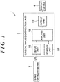
- FIG. 1 shows one embodiment of an X-ray diffraction measurement apparatus that is an apparatus for executing the method for displaying measurement results from X-ray diffraction measurement according to the present invention.
- the X-ray diffraction measurement apparatus 1 shown in FIG. 1 has an X-ray diffractometer 2, a crystal phase identification unit 3, and a display device 4.
- the display device 4 is, e.g., a flat panel display device.
- the display device 4 may be configured integrally with the crystal phase identification unit 3.
- the X-ray diffractometer 2 has a goniometer 7, an X-ray generation device 8, a collimator 9, an X-ray detector 10, a control unit 11, and an input/output device 12, as shown in FIG. 2 .
- the goniometer 7 is an angle-measuring instrument.
- a sample stage 15 that supports a sample S and rotates is provided to a central portion of the goniometer 7.
- the sample stage 15 rotates about a central axis (axis passing through the plane of the drawing depicting FIG. 2 ) X0 that passes therethrough.
- the collimator 9 has a pinhole for narrowing X-rays into a beam shape.
- the X-ray detector 10 is a two-dimensional X-ray detector capable of detecting the position of X-rays within a two-dimensional region (i.e., within a flat region) in addition to having a function for detecting X-ray intensity.
- the X-ray detector 10 can instead be configured as a zero-dimensional X-ray detector or a one-dimensional X-ray detector.
- a zero-dimensional X-ray detector has only a function for detecting X-ray intensity, and does not have position detection capability.
- a one-dimensional X-ray detector is capable of detecting the position of X-rays within a one-dimensional region (i.e., within a linear region) in addition to having a function for detecting X-ray intensity.
- a zero-dimensional X-ray detector or a one-dimensional X-ray detector it is necessary to move the sample or X-ray detector in a linear or rotating manner in order to obtain position information of the X-rays within the flat region.
- a two-dimensional X-ray detector if the X-ray detection surface of the two-dimensional X-ray detector is small, the two-dimensional X-ray detector may be moved in a linear or rotating manner in order to obtain position information of the X-rays within a broader flat region.
- X-rays generated by the X-ray generation device 8 assume the shape of a narrow beam-shaped bundle while passing through the collimator 9.
- the sample S is irradiated with the beam-shaped X-rays.
- a prescribed X-ray diffraction condition is satisfied between the X-rays irradiating the sample S and a crystal lattice plane within the sample S, the X-rays are diffracted by the sample S.
- the X-ray detector 10 detects the X-rays diffracted by the sample S.
- FIG. 2 when the X-rays are incident on the crystal lattice plane within the sample S at an angle ⁇ , the diffraction angle of the X-rays is 2 ⁇ .
- the size of the diffraction angle 2 ⁇ is twice that of the incident angle ⁇ .
- the control unit 11 is formed from a computer, a sequencer, a dedicated circuit, or the like.
- the control unit 11 controls the operations of each of the goniometer 7, the X-ray generation device 8, and the X-ray detector 10.
- the input/output device 12 transmits measurement conditions and various other signals to the control unit 11.
- the input/output unit 12 also transmits output data from the X-ray detector 10 to the crystal phase identification unit 3 in FIG. 1 .
- FIG. 2 shows a reflective X-ray diffractometer, but the X-ray diffractometer may instead be a transmissive X-ray diffractometer.
- the crystal phase identification unit 3 has an input unit 16, a storage unit 17, an analysis unit 18, and an output unit 19 in FIG. 1 .
- the crystal phase identification unit 3 can be configured from a typical computer.
- the input unit 16 can be realized using an input interface
- the output unit 19 can be realized using an output interface
- the storage unit 17 can be realized using a hard disk, memory, or other such device
- the analysis unit 18 can be realized using a central processing unit (CPU) or the like.
- the storage unit 17 functions as a database.
- Information pertaining to X-ray diffraction patterns for a known plurality of crystal phases is registered in the database. Specifically, data about the position and intensity ratio of peaks in 2 ⁇ -I profiles for a known plurality of crystal phases is registered. More specifically, data (d-I data) about "the intensity ratio I" versus "the distance d of crystal lattice planes" is registered.
- numerous pixels 22 are aligned in a planar manner on the X-ray detection surface of the two-dimensional X-ray detector 10, as shown in FIG. 3 .
- the two-dimensional X-ray detector 10 is moved in a scanning manner as indicated by arrow B, whereby X-ray information about a prescribed detection region A is acquired.
- X-ray diffraction data D0 is outputted from an output terminal of the input/output device 12.
- the X-ray diffraction data D0 is formed by individual output signals from the plurality of pixels 22 constituting the X-ray detection surface of the two-dimensional X-ray detector 10.
- the X-ray diffraction data D0 is transmitted to the analysis unit 18 via the input unit 16 of the crystal phase identification unit 3 in FIG. 1 .
- the analysis unit 18 transmits the transmitted X-ray diffraction data D0 to the storage unit 17.
- the storage unit 17 stores the transmitted X-ray diffraction data D0.
- the analysis unit 18 reads out the X-ray diffraction data D0 from the storage unit 17 at a discretionary timing at which analysis is required.
- the analysis unit 18 performs pre-processing on the read-out X-ray diffraction data D0.
- the pre-processing includes, e.g., background correction for eliminating noise.
- the background correction typically includes uniform background correction or median filter correction.
- a data processing unit for performing pre-processing as described above can be provided inside the X-ray diffractometer 2. In such a case, it is unnecessary to perform pre-processing again using the analysis unit 18.
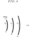
- FIG. 4 schematically shows portions d1, d2, d3 of a plurality of Debye rings obtained from one sample.
- the direction indicated by arrow 2 ⁇ is a diffraction angle 2 ⁇ direction, and the ⁇ directions orthogonal thereto are circumferential directions of the Debye rings.
- the analysis unit 18 in FIG. 1 After the above-mentioned pre-processing is performed, the analysis unit 18 in FIG. 1 generates 2 ⁇ -I data on the basis of the X-ray diffraction data D0.
- the 2 ⁇ -I data indicates X-ray intensity values at each angular position along the diffraction angle 2 ⁇ direction.
- the analysis unit 18 generates image data on the basis of the generated 2 ⁇ -I data and supplies the image data to the display device 4 via the output unit 19.
- a one-dimensional diffraction profile indicated by reference P1 in FIG. 5 or a one-dimensional diffraction profile indicated by reference P1 in FIG. 6 , is thereby displayed within a display screen of the display device 4 in FIG. 1 .
- the analysis unit 18 In addition to generating the 2 ⁇ -I data, the analysis unit 18 generates ⁇ -I data.
- the ⁇ -I data indicates X-ray intensity values at each angular position along the circumferential directions ⁇ of each of the Debye rings d1, d2, d3 in FIG. 4 .
- the analysis unit 18 generates image data on the basis of the generated ⁇ -I data and supplies the image data to the display device 4 via the output unit 19.
- a two-dimensional diffraction pattern including the plurality of Debye rings d1, d2, d3 such as is shown by the two-dimensional diffraction pattern P2 in FIG. 7 is thereby displayed within the display screen of the display device 4 in FIG. 1 .
- the analysis unit 18 In addition to generating image data for displaying the ⁇ -I data as a ring-shaped two-dimensional image, such as is shown by the two-dimensional diffraction pattern P2 in FIG. 7 , the analysis unit 18 generates image data for displaying the ⁇ -I data as a linear two-dimensional image.
- image data may be referred to below as data for a linear-display-format image.
- a two-dimensional diffraction pattern including a linear two-dimensional image displayed by use of the linear-display-format image data may be referred to as a linear-display-format two-dimensional diffraction pattern.
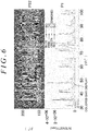
- the analysis unit 18 furthermore generates image data for displaying the one-dimensional diffraction profile P1 and the linear-display-format two-dimensional diffraction pattern P22 so as to be aligned, as shown in FIG. 5 and 6 , and supplies the image data to the display device 4. More specifically, the one-dimensional diffraction profile P1 and the linear-display-format two-dimensional diffraction pattern P22 are displayed so as to be aligned vertically such that the horizontal-axis values; i.e., the angle values for the diffraction angle 2 ⁇ , of the one-dimensional diffraction profile P1 and the linear-display-format two-dimensional diffraction pattern P22 coincide.
- image data for the two-dimensional diffraction pattern is converted such that X-ray intensity data for the same 2 ⁇ angle in the two-dimensional diffraction pattern P22 is displayed linearly, and furthermore the two-dimensional diffraction pattern P22 and the one-dimensional diffraction profile P1 are displayed so as to be aligned such that the horizontal axis (2 ⁇ axis) of the two-dimensional diffraction pattern P22 accurately coincides with the horizontal axis (2 ⁇ axis) of the one-dimensional diffraction profile P1, as shown in FIG. 5 and 6 .
- This makes it possible to visually, quickly, easily, and accurately recognize to which 2 ⁇ angular position a fragmentary diffraction image or spot-shaped diffraction image in the two-dimensional diffraction pattern P22 belongs.
- the position and intensity of diffraction peaks obtained from substances are displayed using colored bars (i.e., straight lines).
- colored bars i.e., straight lines.
- tungsten carbide (WC) is indicated by a blue color
- titanium carbide (TiC) is indicated by a pink color
- information derived from diamond (C) is indicated by a green color
- information derived from silicon carbide (SiC) is indicated by a red color.
- X-ray intensity information in the circumferential direction of a Debye ring is displayed not in a ring shape but rather linearly in the two-dimensional diffraction pattern P22, it is possible to display, in an overlaid manner on the two-dimensional diffraction pattern P22, bars that are exactly the same as the colored bars in the one-dimensional diffraction profile P1.
- the analysis unit 18 in FIG. 1 displays range portions that correspond to both the linear-display-format two-dimensional diffraction pattern P22 and the one-dimensional diffraction profile P1 in an enlarged state, as indicated by reference E.
- the two-dimensional diffraction pattern P22 and the one-dimensional diffraction profile P1 are displayed so as to be enlarged at the same ratio. This makes it possible to quickly, easily, and accurately recognize a fragmentary diffraction image or spot-shaped diffraction image in the two-dimensional diffraction pattern P22.
- the 2 ⁇ angle range may be designated on the two-dimensional diffraction pattern P22, or may be designated on the one-dimensional diffraction profile P1.
- the Debye rings are displayed in a ring-shaped state as shown by the two-dimensional diffraction pattern P2 in FIG. 7 , if the Debye rings appear as fragmentary images or spot-shaped images, it may be difficult to ascertain to which 2 ⁇ diffraction angle the images belong. In particular, when a portion of the two-dimensional diffraction pattern is displayed in an enlarged state, it is even more difficult to ascertain to which 2 ⁇ diffraction angle the images belong. Conversely, in the present embodiment, a diffraction image corresponding to the Debye ring in the two-dimensional diffraction pattern P22 in FIG.
- a sample S including mullite (aluminosilicate) and quartz was placed on a sample stage 15.
- the sample S was then irradiated with X-rays, and a two-dimensional X-ray detector 10 was moved in a rotating manner about the sample S along a diffraction angle 2 ⁇ so that a 2 ⁇ angle range of 10-60° could be reached as a detection region.
- the diffracted X-rays from the sample S were then detected by the two-dimensional X-ray detector 10.
- a sample S including tungsten carbide (WC), titanium carbide (TiC), diamond (C), and silicon carbide (SiC) was placed on a sample stage 15.
- the sample S was then irradiated with X-rays, and a two-dimensional X-ray detector 10 was moved in a rotating manner about the sample S along a diffraction angle 2 ⁇ so that a 2 ⁇ angle range of 30-110° could be reached as a detection region.
- the diffracted X-rays from the sample S were then detected by the two-dimensional X-ray detector 10.
- the inventors proposed the following method for identifying crystal phases in Japanese Patent Laid-open Publication No. 2017-211251 corresponding to EP3249392A1 . Specifically, proposed was a method for identifying crystal phases, the method having:
- a “cluster” is an aggregate of substances or physical quantities that have the same attributes.
- the “prescribed database” is a database in which data about the position and intensity ratio of peaks in X-ray diffraction patterns is registered in advance for each of a plurality of crystal phases.
- This method for identifying crystal phases has the following characteristics.
- ring characteristic factors representing the degree of circumferential-direction uniformity in the intensity of the diffraction patterns can be determined from data about "the X-ray intensity” versus "the angle in the circumferential direction” of the diffraction patterns, and the diffraction patterns can be sorted into the plurality of clusters in accordance with the determined ring characteristic factors.
- Ring characteristic factor is a neologism, conceived of by the inventors, that refers to elements representing the degree of circumferential-direction uniformity in the intensity of diffraction patterns. Ring characteristic factors clarify the uniformity in the circumferential direction of the diffraction patterns.
- sorting the diffraction patterns into a plurality of clusters in accordance with the determined ring characteristic factors makes it possible to sort diffraction patterns having differing degrees of uniformity in the circumferential direction into different clusters.
- the various values indicated in FIG. 9 where the X-ray intensity I in the ⁇ -I data is represented as variable X, can be applied as "ring characteristic factors.”
- FIG. 10 shows an X-ray diffraction measurement apparatus 51 applied to the second embodiment.
- the analysis unit 18 has a detection unit 52, a clustering unit 53, and a search unit 54. These units can be realized using an operation part of a CPU.
- the detection means 52 reads out X-ray diffraction data stored in the storage unit 17, performs pre-processing on X-ray diffraction data, and then converts the X-ray diffraction data to 2 ⁇ -I data.
- the detection unit 52 detects the position and intensity of peaks in a 2 ⁇ -I profile. This process is referred to as a "peak search.”
- the detection unit 52 produces data (i.e., ⁇ -I data) about "the X-ray intensity I" versus "the angle ⁇ in the circumferential direction” in diffraction patterns at the position of peaks in the 2 ⁇ -I profile.
- the detection unit 52 calculates or produces ring characteristic factors from the ⁇ -I data.
- the clustering unit 53 sorts the diffraction patterns into a plurality of clusters in accordance with the ring characteristic factors.
- the search unit 54 under the hypothesis that some or all of the diffraction patterns included in the same cluster are derived from the same crystal phase, searches a database for a crystal phase showing peak positions and peak intensity ratios that highly conform with a set comprising the position and the intensity ratio of peaks in diffraction patterns that were sorted into the same cluster and extracts a crystal phase candidate.
- the measured two-dimensional diffraction patterns and the registered information within the database are compared in consideration of uniformity in the circumferential direction of two-dimensional diffraction patterns that correspond to Debye rings. Therefore, the present embodiment avoids an undesirable circumstance in which a crystal phase candidate is listed in a search result on the basis of a set of diffraction patterns having differing degrees of uniformity in the circumferential direction. As a result, it is possible to perform highly precise analysis.
- the X-ray diffraction measurement of the present embodiment is configured such that a search is performed in consideration of uniformity in the circumferential direction of two-dimensional diffraction patterns that correspond to Debye rings, as described above, wherein the X-ray diffraction measurement is furthermore configured such that a one-dimensional diffraction profile P1 and a linear-display-format two-dimensional diffraction pattern P22 are displayed so as to be aligned such that the 2 ⁇ angular positions coincide, as shown in FIG. 5 and 6 .
- the present embodiment thereby makes it possible to simultaneously recognize screen displays such as are shown in FIG.
- the present invention is applied to powder X-ray diffraction measurement, but the present invention can instead be applied to types of X-ray diffraction measurement other than powder X-ray diffraction measurement.
Landscapes
- Chemical & Material Sciences (AREA)
- Crystallography & Structural Chemistry (AREA)
- Physics & Mathematics (AREA)
- Health & Medical Sciences (AREA)
- Life Sciences & Earth Sciences (AREA)
- Analytical Chemistry (AREA)
- Biochemistry (AREA)
- General Health & Medical Sciences (AREA)
- General Physics & Mathematics (AREA)
- Immunology (AREA)
- Pathology (AREA)
- Analysing Materials By The Use Of Radiation (AREA)
Abstract
Description
- The present invention relates to a method for displaying measurement results from X-ray diffraction measurement, which is a measurement in which a sample is irradiated with X-rays and the X-rays diffracted by the sample are detected by an X-ray detector.
- Most solid substances exist in a crystal state. The term "crystalline" typically refers to the state of being in a crystal state or to substances in a crystal state. Many solid substances can be formed by aggregating numerous fine crystal particles. Many substances formed by aggregating crystal particles are referred to as "polycrystalline substances."
- X-ray diffraction measurement includes various measurement techniques, such as powder X-ray diffraction measurement, thin-film measurement, micro-area X-ray diffraction measurement, and small-angle X-ray scattering measurement. For example, powder X-ray diffraction measurement is a type of X-ray diffraction measurement that is performed using pulverulent crystals or polycrystalline substances as samples.
- In powder X-ray diffraction measurement, an X-ray diffraction pattern for a sample is obtained by a measurement in which an X-ray diffractometer is used. The X-ray diffraction pattern is unique to each crystal phase. Analyzing this X-ray diffraction pattern makes it possible to identify the crystal phases included in a sample. "Crystal phase" is a concept for representing a substance included in a sample when that substance is in a crystal state.
- Typically, provided that the number of crystal particles in a sample is sufficiently high and the orientation of lattice planes is random, there will necessarily be a lattice plane at an angle that satisfies diffraction conditions with respect to X-rays incident on the sample. X-rays diffracted by a lattice plane at a diffraction angle 2θ progress along a conical generatrix at a half-vertical angle of 2θ when 2θ < 90°, and progress along a conical generatrix at a half-vertical angle of (180° - 2θ) when 2θ > 90°, as shown in
FIG. 3 . Specifically, X-rays diffracted by a sample comprising pulverulent crystal or polycrystalline substances form numerous cones C having different central angles. When these X-rays are received within the range of an area A0 by an X-ray detection surface of anX-ray detector 10, concentric diffraction patterns such as are shown by the two-dimensional diffraction pattern P2 inFIG. 7 are obtained. Such arcuate diffraction patterns are referred to as "Debye-Scherrer rings" or "Debye rings." - Conventional X-ray diffraction measurement is disclosed in
US Patent No. 7,885,383 .FIG. 1 ofUS Patent No. 7,885,383 shows that the intensity of X-rays contributing to the formation of a Debye ring is measured along a circumferential direction (γ (gamma) direction) orthogonal to the 2θ direction of the Debye ring. - Also,
FIG. 4 ofUS Patent No. 7,885,383 shows that a γ-I profile and a two-dimensional diffraction pattern including a plurality of Debye rings are displayed so as to be aligned. A γ-I profile is an X-ray intensity distribution represented on a coordinate system in which the horizontal axis shows γ-direction angle values and the vertical axis shows X-ray intensity values. AlthoughUS Patent No. 7,885,383 shows that X-ray intensity data in the circumferential direction of a Debye ring is displayed, a problem is presented in that the display of the circumferential-direction X-ray intensity data is not advantageously used to a sufficient degree. - The present invention was contrived in view of the conventional problem described above, the aim of the present invention being to enable the correlation between X-ray information in the circumferential direction of a Debye ring and a 2θ angular position to be recognized in a visually clear and accurate manner.
- In consideration of powder X-ray diffraction measurement, crystal phase identification in which powder diffraction data is used is conventionally known. "Powder diffraction data" is, e.g., a one-dimensional profile such as is shown by reference P1 in
FIG. 7 . Analyzing what kinds of substances (crystalline substances) are included in a sample from the position and intensity (height and integral intensity) of peaks in the one-dimensional profile P1 is one example of crystal phase identification in which a powder diffraction pattern is used. - Actual samples to be analyzed often include a plurality of substances rather than only one substance. Specifically, actual samples are often mixed substances. In such cases, because the powder diffraction pattern comprises a combination of diffraction patterns of a plurality of substances, it is difficult for a technician to perform an operation for identifying crystals without further assistance. Thus, it is typical to perform an operation in which a search-match algorithm executed by computer software is used to compare a diffraction pattern obtained by measurement and a database in which numerous known diffraction patterns of substances are stored, thereby determining a plurality of substances included in a sample to be analyzed. The Hanawalt method has long been known as a search-match algorithm.
- In recent years, two-dimensional X-ray detectors have become mainstream as X-ray detectors. Until now, crystal phase identification has been performed by converting two-dimensional diffraction data measured by a two-dimensional X-ray detector to a one-dimensional profile and performing search and match using the converted one-dimensional diffraction profile. For an ideal powder sample, a Debye ring that is a diffraction image having the aforementioned arcuate shape or an ellipsoidal shape is imprinted in the two-dimensional diffraction data. This Debye ring corresponds to a diffraction peak in a one-dimensional diffraction profile.
- However, when the powder sample is not ideal, such as when the sample contains a strongly oriented substance or coarse particles, then the Debye ring might not have a clear arcuate or ellipsoidal shape but rather be intermittently broken, or a spot-shaped diffraction image might appear. Such sample information cannot be obtained using a conventional scintillation counter or high-speed one-dimensional X-ray detector. Such sample information is reliably created by two-dimensional X-ray detectors.
- Displaying a one-dimensional diffraction profile P1 and a two-dimensional diffraction pattern P2 that includes a ring-shaped diffraction image so as to be aligned, as shown in
FIG. 7 , is conceivable as a method for displaying measurement results from X-ray diffraction measurement. According to such a display method, it is possible to visually capture information J1 about whether preferred orientation is strong and information J2 about whether coarse particles are present. However, in this display method, the Debye ring is displayed with an arcuate or ellipsoidal shape. Therefore, even if the horizontal axis (2θ) of the one-dimensional diffraction profile P1 and the horizontal axis (2θ) of an equatorial (central) portion of the two-dimensional diffraction pattern P2 are caused to coincide and the one-dimensional diffraction profile P1 and the two-dimensional diffraction pattern P2 are displayed so as to be aligned, the difficulty of comparing the position of a peak in the one-dimensional diffraction profile P1 and the position of a fragmentary image or spot-shaped image in the two-dimensional diffraction pattern P2 increases as the 2θ angular position on the two-dimensional diffraction pattern P2 gets further from the equator. - However, the inventors converted two-dimensional image data for the two-dimensional diffraction pattern such that X-ray intensity data for the same 2θ angle in a two-dimensional diffraction pattern P22 is displayed linearly, and furthermore displayed the resulting data so as to be aligned such that the horizontal axis (2θ axis) of the two-dimensional data accurately coincides with the horizontal axis of the one-dimensional diffraction profile P1, as shown in, e.g.,
FIG. 5 and6 . This made it possible to visually, quickly, easily, and accurately recognize to which 2θ angular position the fragmentary image or spot-shaped image in the two-dimensional diffraction pattern P22 belongs. - Recently, in order to indicate a candidate for a contained crystal phase or indicate a result following crystal phase identification in a one-dimensional diffraction profile P1, the position and intensity of diffraction peaks obtained from substances have often been displayed using colored bars (i.e., straight lines). For example, in
FIG. 6 , as pertains to each of the one-dimensional diffraction profile P1 and the two-dimensional diffraction pattern P22, information derived from tungsten carbide (WC) is indicated by a blue color, information derived from titanium carbide (TiC) is indicated by a pink color, information derived from diamond (C) is indicated by a green color, and information derived from silicon carbide (SiC) is indicated by a red color. - According to the present invention, because X-ray intensity information in the circumferential direction of a Debye ring is displayed not in a ring shape but linearly in the two-dimensional diffraction pattern P22, it is possible to display, in an overlaid manner on the two-dimensional diffraction pattern P22, bars that are exactly the same as the colored bars in the one-dimensional diffraction profile P1. As a result, it is possible in particular to easily recognize the position, on the two-dimensional diffraction pattern P22, of a diffraction peak of a candidate for a contained crystal phase. This feature provides an especially great advantage for users.
- (Solution 1) A method for displaying measurement results from X-ray diffraction measurement according to the present invention involves a measurement in which a sample is irradiated with X-rays and the X-rays diffracted by the sample are detected by an X-ray detector, wherein the method comprises: forming a one-dimensional diffraction profile by displaying, on the basis of output data from the X-ray detector, a 2θ-I profile within a coordinate system in which one orthogonal coordinate axis shows 2θ angle values and another orthogonal coordinate axis shows X-ray intensity values; forming a two-dimensional diffraction pattern by displaying, linearly for each 2θ angle value and on the basis of output data from the X-ray detector, X-ray intensity data in the circumferential direction of a plurality of Debye rings formed at each 2θ angle by X-rays diffracted by the sample; and displaying the two-dimensional diffraction pattern and the 2θ-I profile so as to be aligned such that the 2θ angle values of both coincide with each other.
- According to the present invention, X-ray intensity data for the same 2θ angle in a two-dimensional diffraction pattern is displayed linearly. Moreover, the two-dimensional diffraction pattern and the one-dimensional diffraction profile are displayed so as to be aligned such that a coordinate axis (2θ angle axis) of the two-dimensional diffraction pattern accurately coincides with a coordinate axis (2θ angle axis) of the one-dimensional diffraction profile. As a result, it is possible to visually, quickly, easily, and accurately recognize to which 2θ angular position a fragmentary diffraction image or spot-shaped diffraction image in the two-dimensional diffraction pattern belongs.
- (Solution 2) In a second aspect of the present invention, when a desired enlargement range is designated in the two-dimensional diffraction pattern (P22) or in the one-dimensional diffraction profile (P1), both the two-dimensional diffraction pattern (P22) and the one-dimensional diffraction profile (P1) in the designated range are displayed so as to be enlarged at the same ratio and in an aligned state.
- (Solution 3) In a third aspect of the present invention, the X-ray diffraction measurement has a step for performing a crystal phase candidate search in consideration of uniformity in the circumferential direction of the Debye rings.
- (Solution 4) In a fourth aspect of the present invention, the method comprises: (1) a step for determining β-I data, which is data about "the X-ray intensity" versus "the angle in the circumferential direction of the Debye rings"; (2) a step for classifying the diffraction patterns that correspond to the Debye rings into clusters on the basis of the β-I data; and (3) a step for performing a crystal phase candidate search within the same clusters.
- According to the present invention, X-ray intensity data for the same 2θ angle in a two-dimensional diffraction pattern is displayed linearly. Moreover, the two-dimensional diffraction pattern and the one-dimensional diffraction profile are displayed so as to be aligned such that the coordinate axis (2θ angle axis) of the two-dimensional diffraction pattern accurately coincides with the coordinate axis (2θ angle axis) of the one-dimensional diffraction profile. As a result, it is possible to visually, quickly, easily, and accurately recognize to which 2θ angular position a fragmentary diffraction image or spot-shaped diffraction image in the two-dimensional diffraction pattern belongs.
-
-
FIG. 1 is a diagram showing one embodiment of an X-ray diffraction measurement apparatus in which the display method according to the present invention is used; -
FIG. 2 is a diagram showing one embodiment of the X-ray diffractometer inFIG. 1 ; -
FIG. 3 is a diagram showing Debye rings and an X-ray detector; -
FIG. 4 is a diagram schematically showing a portion of Debye rings; -
FIG. 5 is a diagram showing one embodiment of the display method according to the present invention; -
FIG. 6 is a diagram showing another embodiment of the display method according to the present invention; -
FIG. 7 is a diagram showing a reference example of a method for displaying measurement results; -
FIG. 8 is a diagram showing a further embodiment of the display method according to the present invention; -
FIG. 9 is a diagram showing an example of ring characteristic factors utilized in one example of an X-ray diffractometer to which the display method according to the present invention can be applied; and -
FIG. 10 is a diagram showing a further embodiment of an X-ray diffraction measurement apparatus in which the display method according to the present invention is used. - A method for displaying measurement results from X-ray diffraction measurement according to the present invention is described below on the basis of the embodiments. As shall be apparent, the present invention is in no way limited to these embodiments. There may be cases where the drawings accompanying the present specification show configuration elements at proportions different from actual proportions in order to facilitate comprehension of characteristic portions.
-
FIG. 1 shows one embodiment of an X-ray diffraction measurement apparatus that is an apparatus for executing the method for displaying measurement results from X-ray diffraction measurement according to the present invention. The X-raydiffraction measurement apparatus 1 shown inFIG. 1 has anX-ray diffractometer 2, a crystalphase identification unit 3, and adisplay device 4. Thedisplay device 4 is, e.g., a flat panel display device. Thedisplay device 4 may be configured integrally with the crystalphase identification unit 3. - The
X-ray diffractometer 2 has agoniometer 7, anX-ray generation device 8, acollimator 9, anX-ray detector 10, acontrol unit 11, and an input/output device 12, as shown inFIG. 2 . Thegoniometer 7 is an angle-measuring instrument. Asample stage 15 that supports a sample S and rotates is provided to a central portion of thegoniometer 7. Thesample stage 15 rotates about a central axis (axis passing through the plane of the drawing depictingFIG. 2 ) X0 that passes therethrough. Thecollimator 9 has a pinhole for narrowing X-rays into a beam shape. - The
X-ray detector 10 is a two-dimensional X-ray detector capable of detecting the position of X-rays within a two-dimensional region (i.e., within a flat region) in addition to having a function for detecting X-ray intensity. TheX-ray detector 10 can instead be configured as a zero-dimensional X-ray detector or a one-dimensional X-ray detector. A zero-dimensional X-ray detector has only a function for detecting X-ray intensity, and does not have position detection capability. A one-dimensional X-ray detector is capable of detecting the position of X-rays within a one-dimensional region (i.e., within a linear region) in addition to having a function for detecting X-ray intensity. When a zero-dimensional X-ray detector or a one-dimensional X-ray detector is used, it is necessary to move the sample or X-ray detector in a linear or rotating manner in order to obtain position information of the X-rays within the flat region. Even when a two-dimensional X-ray detector is used, if the X-ray detection surface of the two-dimensional X-ray detector is small, the two-dimensional X-ray detector may be moved in a linear or rotating manner in order to obtain position information of the X-rays within a broader flat region. - X-rays generated by the
X-ray generation device 8 assume the shape of a narrow beam-shaped bundle while passing through thecollimator 9. The sample S is irradiated with the beam-shaped X-rays. When a prescribed X-ray diffraction condition is satisfied between the X-rays irradiating the sample S and a crystal lattice plane within the sample S, the X-rays are diffracted by the sample S. TheX-ray detector 10 detects the X-rays diffracted by the sample S. As shown inFIG. 2 , when the X-rays are incident on the crystal lattice plane within the sample S at an angle θ, the diffraction angle of the X-rays is 2θ. The size of the diffraction angle 2θ is twice that of the incident angle θ. - The
control unit 11 is formed from a computer, a sequencer, a dedicated circuit, or the like. Thecontrol unit 11 controls the operations of each of thegoniometer 7, theX-ray generation device 8, and theX-ray detector 10. The input/output device 12 transmits measurement conditions and various other signals to thecontrol unit 11. The input/output unit 12 also transmits output data from theX-ray detector 10 to the crystalphase identification unit 3 inFIG. 1 .FIG. 2 shows a reflective X-ray diffractometer, but the X-ray diffractometer may instead be a transmissive X-ray diffractometer. - The crystal
phase identification unit 3 has aninput unit 16, astorage unit 17, ananalysis unit 18, and anoutput unit 19 inFIG. 1 . The crystalphase identification unit 3 can be configured from a typical computer. In such a case, theinput unit 16 can be realized using an input interface, theoutput unit 19 can be realized using an output interface, thestorage unit 17 can be realized using a hard disk, memory, or other such device, and theanalysis unit 18 can be realized using a central processing unit (CPU) or the like. - The
storage unit 17 functions as a database. Information pertaining to X-ray diffraction patterns for a known plurality of crystal phases is registered in the database. Specifically, data about the position and intensity ratio of peaks in 2θ-I profiles for a known plurality of crystal phases is registered. More specifically, data (d-I data) about "the intensity ratio I" versus "the distance d of crystal lattice planes" is registered. - In the present embodiment,
numerous pixels 22 are aligned in a planar manner on the X-ray detection surface of the two-dimensional X-ray detector 10, as shown inFIG. 3 . The two-dimensional X-ray detector 10 is moved in a scanning manner as indicated by arrow B, whereby X-ray information about a prescribed detection region A is acquired. InFIG. 2 , X-ray diffraction data D0 is outputted from an output terminal of the input/output device 12. The X-ray diffraction data D0 is formed by individual output signals from the plurality ofpixels 22 constituting the X-ray detection surface of the two-dimensional X-ray detector 10. - The X-ray diffraction data D0 is transmitted to the
analysis unit 18 via theinput unit 16 of the crystalphase identification unit 3 inFIG. 1 . Theanalysis unit 18 transmits the transmitted X-ray diffraction data D0 to thestorage unit 17. Thestorage unit 17 stores the transmitted X-ray diffraction data D0. Theanalysis unit 18 reads out the X-ray diffraction data D0 from thestorage unit 17 at a discretionary timing at which analysis is required. Theanalysis unit 18 performs pre-processing on the read-out X-ray diffraction data D0. The pre-processing includes, e.g., background correction for eliminating noise. The background correction typically includes uniform background correction or median filter correction. A data processing unit for performing pre-processing as described above can be provided inside theX-ray diffractometer 2. In such a case, it is unnecessary to perform pre-processing again using theanalysis unit 18. -
FIG. 4 schematically shows portions d1, d2, d3 of a plurality of Debye rings obtained from one sample. The direction indicated by arrow 2θ is a diffraction angle 2θ direction, and the β directions orthogonal thereto are circumferential directions of the Debye rings. After the above-mentioned pre-processing is performed, theanalysis unit 18 inFIG. 1 generates 2θ-I data on the basis of the X-ray diffraction data D0. The 2θ-I data indicates X-ray intensity values at each angular position along the diffraction angle 2θ direction. - The
analysis unit 18 generates image data on the basis of the generated 2θ-I data and supplies the image data to thedisplay device 4 via theoutput unit 19. A one-dimensional diffraction profile indicated by reference P1 inFIG. 5 , or a one-dimensional diffraction profile indicated by reference P1 inFIG. 6 , is thereby displayed within a display screen of thedisplay device 4 inFIG. 1 . - In addition to generating the 2θ-I data, the
analysis unit 18 generates β-I data. The β-I data indicates X-ray intensity values at each angular position along the circumferential directions β of each of the Debye rings d1, d2, d3 inFIG. 4 . Theanalysis unit 18 generates image data on the basis of the generated β-I data and supplies the image data to thedisplay device 4 via theoutput unit 19. A two-dimensional diffraction pattern including the plurality of Debye rings d1, d2, d3 such as is shown by the two-dimensional diffraction pattern P2 inFIG. 7 is thereby displayed within the display screen of thedisplay device 4 inFIG. 1 . - In addition to generating image data for displaying the β-I data as a ring-shaped two-dimensional image, such as is shown by the two-dimensional diffraction pattern P2 in
FIG. 7 , theanalysis unit 18 generates image data for displaying the β-I data as a linear two-dimensional image. Such image data may be referred to below as data for a linear-display-format image. Also, a two-dimensional diffraction pattern including a linear two-dimensional image displayed by use of the linear-display-format image data may be referred to as a linear-display-format two-dimensional diffraction pattern. When such linear-display-format image data is supplied to thedisplay device 4 via theoutput unit 19, a two-dimensional diffraction pattern that includes linear X-ray intensity information such as is indicated by reference P22 inFIG. 5 , or a two-dimensional diffraction pattern that includes linear X-ray intensity information such as is indicated by reference P22 inFIG. 6 , is displayed within the display screen of thedisplay device 4. - The
analysis unit 18 furthermore generates image data for displaying the one-dimensional diffraction profile P1 and the linear-display-format two-dimensional diffraction pattern P22 so as to be aligned, as shown inFIG. 5 and6 , and supplies the image data to thedisplay device 4. More specifically, the one-dimensional diffraction profile P1 and the linear-display-format two-dimensional diffraction pattern P22 are displayed so as to be aligned vertically such that the horizontal-axis values; i.e., the angle values for the diffraction angle 2θ, of the one-dimensional diffraction profile P1 and the linear-display-format two-dimensional diffraction pattern P22 coincide. - In the present embodiment as described above, image data for the two-dimensional diffraction pattern is converted such that X-ray intensity data for the same 2θ angle in the two-dimensional diffraction pattern P22 is displayed linearly, and furthermore the two-dimensional diffraction pattern P22 and the one-dimensional diffraction profile P1 are displayed so as to be aligned such that the horizontal axis (2θ axis) of the two-dimensional diffraction pattern P22 accurately coincides with the horizontal axis (2θ axis) of the one-dimensional diffraction profile P1, as shown in
FIG. 5 and6 . This makes it possible to visually, quickly, easily, and accurately recognize to which 2θ angular position a fragmentary diffraction image or spot-shaped diffraction image in the two-dimensional diffraction pattern P22 belongs. - Additionally, in the present embodiment, in order to indicate a candidate for a contained crystal phase or indicate a result following crystal phase identification in the one-dimensional diffraction profile P1, the position and intensity of diffraction peaks obtained from substances are displayed using colored bars (i.e., straight lines). For example, in
FIG. 6 , as pertains to each of the one-dimensional diffraction profile P1 and the two-dimensional diffraction pattern P22, information derived from tungsten carbide (WC) is indicated by a blue color, information derived from titanium carbide (TiC) is indicated by a pink color, information derived from diamond (C) is indicated by a green color, and information derived from silicon carbide (SiC) is indicated by a red color. - According to the present embodiment, because X-ray intensity information in the circumferential direction of a Debye ring is displayed not in a ring shape but rather linearly in the two-dimensional diffraction pattern P22, it is possible to display, in an overlaid manner on the two-dimensional diffraction pattern P22, bars that are exactly the same as the colored bars in the one-dimensional diffraction profile P1. As a result, it is possible in particular to easily recognize the position, on the two-dimensional diffraction pattern P22, of a diffraction peak of a candidate for a contained crystal phase. This feature provides an especially great advantage for users.
- In the present embodiment, when a desired 2θ angle range (desired range on horizontal axis) is designated as shown in
FIG. 8 , theanalysis unit 18 inFIG. 1 displays range portions that correspond to both the linear-display-format two-dimensional diffraction pattern P22 and the one-dimensional diffraction profile P1 in an enlarged state, as indicated by reference E. In particular, the two-dimensional diffraction pattern P22 and the one-dimensional diffraction profile P1 are displayed so as to be enlarged at the same ratio. This makes it possible to quickly, easily, and accurately recognize a fragmentary diffraction image or spot-shaped diffraction image in the two-dimensional diffraction pattern P22. The 2θ angle range may be designated on the two-dimensional diffraction pattern P22, or may be designated on the one-dimensional diffraction profile P1. - When the Debye rings are displayed in a ring-shaped state as shown by the two-dimensional diffraction pattern P2 in
FIG. 7 , if the Debye rings appear as fragmentary images or spot-shaped images, it may be difficult to ascertain to which 2θ diffraction angle the images belong. In particular, when a portion of the two-dimensional diffraction pattern is displayed in an enlarged state, it is even more difficult to ascertain to which 2θ diffraction angle the images belong. Conversely, in the present embodiment, a diffraction image corresponding to the Debye ring in the two-dimensional diffraction pattern P22 inFIG. 8 is displayed linearly, and moreover the 2θ axis (horizontal axis) of the one-dimensional diffraction profile P1 coincides with the 2θ axis of the two-dimensional diffraction pattern P22. Therefore, it is possible to quickly, easily, and accurately recognize the 2θ angular position of a fragmentary diffraction image or spot-shaped diffraction image present in the enlarged display. - In
FIG. 2 , a sample S including mullite (aluminosilicate) and quartz was placed on asample stage 15. The sample S was then irradiated with X-rays, and a two-dimensional X-ray detector 10 was moved in a rotating manner about the sample S along a diffraction angle 2θ so that a 2θ angle range of 10-60° could be reached as a detection region. The diffracted X-rays from the sample S were then detected by the two-dimensional X-ray detector 10. - On the basis of X-ray diffraction data for each pixel outputted from the two-
dimensional X-ray detector 10, measurement results were displayed within a screen of thedisplay device 4 inFIG. 1 , and the display shown inFIG. 5 was obtained. InFIG. 5 , a one-dimensional diffraction profile P1 and a linear-display-format two-dimensional diffraction pattern P22 were displayed so as to be aligned such that the 2θ angle values on 2θ axes coincided. In the two-dimensional diffraction pattern P22, in which Debye rings are displayed linearly, it was recognized that the intensity in the circumferential direction of Debye rings derived from fine particles was homogeneous. It was also recognized that diffraction images derived from coarse particles appeared in a spot shape. The values of the 2θ angular positions of these spot-shaped diffraction images could easily be visually confirmed. - In
FIG. 2 , a sample S including tungsten carbide (WC), titanium carbide (TiC), diamond (C), and silicon carbide (SiC) was placed on asample stage 15. The sample S was then irradiated with X-rays, and a two-dimensional X-ray detector 10 was moved in a rotating manner about the sample S along a diffraction angle 2θ so that a 2θ angle range of 30-110° could be reached as a detection region. The diffracted X-rays from the sample S were then detected by the two-dimensional X-ray detector 10. - On the basis of X-ray diffraction data for each pixel outputted from the two-
dimensional X-ray detector 10, measurement results were displayed within a screen of thedisplay device 4 inFIG. 1 , and the display shown inFIG. 6 was obtained. InFIG. 6 , a one-dimensional diffraction profile P1 and a linear-display-format two-dimensional diffraction pattern P22 were displayed so as to be aligned such that the 2θ angle values on 2θ axes coincided. In the two-dimensional diffraction pattern P22, in which Debye rings are displayed linearly, it was recognized that diffraction images derived from selectively oriented crystals appeared in a partial manner in the circumferential direction. It was also recognized that diffraction images derived from coarse particles appeared in a spot shape. The values of the 2θ angular positions of these spot-shaped diffraction images could easily be visually confirmed. It was also recognized that diffraction images derived from non-oriented fine particles appeared to be homogeneous in the circumferential direction. - The inventors proposed the following method for identifying crystal phases in Japanese Patent Laid-open Publication No.
2017-211251 EP3249392A1 . Specifically, proposed was a method for identifying crystal phases, the method having: - (1) a step for producing, on the basis of two-dimensional X-ray diffraction data that comprises output signals from the two-
dimensional X-ray detector 10 inFIG. 2 , X-ray intensity data; i.e., β-I data for each angular position in the circumferential directions β of the Debye rings inFIG. 4 ; - (2) a step for sorting two-dimensional diffraction patterns that correspond to the Debye rings in
FIG. 4 into a plurality of clusters on the basis of the above-mentioned β-I data; and - (3) a step for searching for a candidate for a crystal phase contained in a sample from a prescribed database on the basis of a set comprising the position and the intensity ratio of peaks in two-dimensional diffraction patterns that were sorted into the same cluster.
- In the above description, a "cluster" is an aggregate of substances or physical quantities that have the same attributes. The "prescribed database" is a database in which data about the position and intensity ratio of peaks in X-ray diffraction patterns is registered in advance for each of a plurality of crystal phases.
- This method for identifying crystal phases has the following characteristics.
- (A) The position and intensity of peaks in a plurality of diffraction patterns (e.g., the plurality of ring-shaped diffraction images d1-d5 in the two-dimensional diffraction pattern P2 in
FIG. 7 ) are determined from X-ray diffraction data outputted from an X-ray detector (e.g.,reference 10 inFIG. 2 ), and data about "the X-ray intensity" versus "the angle in the circumferential direction (e.g., the β direction inFIG. 4 )" is produced for each diffraction pattern. The plurality of diffraction patterns indicate rings included in a plurality of concentric Debye rings. - (B) The diffraction patterns are sorted into a plurality of clusters on the basis of the produced data about "the X-ray intensity" versus "the angle in the circumferential direction." The diffraction patterns are thereby sorted into the plurality of clusters in accordance with uniformity in the circumferential direction.
- (C) A search for a candidate for a crystal phase included in a sample from a prescribed database is performed on the basis of a set comprising the position and the intensity ratio of peaks in diffraction patterns that were sorted into the same cluster. A crystal phase candidate search is thereby performed on the basis of sets of diffraction patterns for which the uniformity in the circumferential direction is similar. Therefore, in identification of the crystal phases, the crystal phase candidate search is performed with greater precision and the analysis precision is also improved.
- Furthermore, in the method for identifying crystal phases described above, ring characteristic factors representing the degree of circumferential-direction uniformity in the intensity of the diffraction patterns can be determined from data about "the X-ray intensity" versus "the angle in the circumferential direction" of the diffraction patterns, and the diffraction patterns can be sorted into the plurality of clusters in accordance with the determined ring characteristic factors. "Ring characteristic factor" is a neologism, conceived of by the inventors, that refers to elements representing the degree of circumferential-direction uniformity in the intensity of diffraction patterns. Ring characteristic factors clarify the uniformity in the circumferential direction of the diffraction patterns. Therefore, sorting the diffraction patterns into a plurality of clusters in accordance with the determined ring characteristic factors makes it possible to sort diffraction patterns having differing degrees of uniformity in the circumferential direction into different clusters. The various values indicated in
FIG. 9 , where the X-ray intensity I in the β-I data is represented as variable X, can be applied as "ring characteristic factors." -
FIG. 10 shows an X-raydiffraction measurement apparatus 51 applied to the second embodiment. In the X-raydiffraction measurement apparatus 51, elements that are the same as the configuration elements of the X-raydiffraction measurement apparatus 1 shown inFIG. 1 are labelled with the same references. In the X-raydiffraction measurement apparatus 51, theanalysis unit 18 has adetection unit 52, aclustering unit 53, and asearch unit 54. These units can be realized using an operation part of a CPU. - The detection means 52 reads out X-ray diffraction data stored in the
storage unit 17, performs pre-processing on X-ray diffraction data, and then converts the X-ray diffraction data to 2θ-I data. Thedetection unit 52 detects the position and intensity of peaks in a 2θ-I profile. This process is referred to as a "peak search." Thedetection unit 52 produces data (i.e., β-I data) about "the X-ray intensity I" versus "the angle β in the circumferential direction" in diffraction patterns at the position of peaks in the 2θ-I profile. Thedetection unit 52 calculates or produces ring characteristic factors from the β-I data. - The
clustering unit 53 sorts the diffraction patterns into a plurality of clusters in accordance with the ring characteristic factors. - The
search unit 54, under the hypothesis that some or all of the diffraction patterns included in the same cluster are derived from the same crystal phase, searches a database for a crystal phase showing peak positions and peak intensity ratios that highly conform with a set comprising the position and the intensity ratio of peaks in diffraction patterns that were sorted into the same cluster and extracts a crystal phase candidate. - According to the X-ray diffraction measurement in the present embodiment, the measured two-dimensional diffraction patterns and the registered information within the database are compared in consideration of uniformity in the circumferential direction of two-dimensional diffraction patterns that correspond to Debye rings. Therefore, the present embodiment avoids an undesirable circumstance in which a crystal phase candidate is listed in a search result on the basis of a set of diffraction patterns having differing degrees of uniformity in the circumferential direction. As a result, it is possible to perform highly precise analysis.
- The X-ray diffraction measurement of the present embodiment is configured such that a search is performed in consideration of uniformity in the circumferential direction of two-dimensional diffraction patterns that correspond to Debye rings, as described above, wherein the X-ray diffraction measurement is furthermore configured such that a one-dimensional diffraction profile P1 and a linear-display-format two-dimensional diffraction pattern P22 are displayed so as to be aligned such that the 2θ angular positions coincide, as shown in
FIG. 5 and6 . The present embodiment thereby makes it possible to simultaneously recognize screen displays such as are shown inFIG. 5 and6 ; i.e., screen displays in which the relationship between circumferential-direction (β-direction) X-ray intensity information and the 2θ angular positions is clearly represented, when the process is executed in consideration of the uniformity in the circumferential direction of the diffraction pattern. Therefore, an analysis can be performed with especially high reliability. - The present invention was described above using the example of preferred embodiments, but the present invention is in no way limited by these embodiments; a variety of modifications can be made within the scope of the invention recited in the claims.
- For example, in the embodiments described above, the present invention is applied to powder X-ray diffraction measurement, but the present invention can instead be applied to types of X-ray diffraction measurement other than powder X-ray diffraction measurement.
- 1: X-ray diffraction measurement apparatus, 2: X-ray diffractometer, 3: Crystal phase identification unit, 4: Display device, 7: Goniometer, 8: X-ray generation device, 9: Collimator, 10: X-ray detector, 11: Control unit, 12: Input/output device, 15: Sample stage, 22: Pixel, 51: X-ray diffraction measurement apparatus, A0: Detection region, C: Cone, d1, d2, d3: Debye ring, D0: X-ray diffraction data, E: Enlarged display, J1: Information about whether preferred orientation is strong, J2: Information about whether coarse particles are present, P1: One-dimensional diffraction profile, P2: Two-dimensional diffraction pattern, P22: Linear-display-format two-dimensional diffraction pattern, S: Sample, X0: Central axis
Claims (4)
- A method for displaying measurement results from X-ray diffraction measurement, which is a measurement in which a sample (S) is irradiated with X-rays outputted from an X-ray generation device (8) and the X-rays diffracted by the sample (S) are detected by an X-ray detector (10), wherein the method comprises:forming a one-dimensional diffraction profile (P1) by displaying, on the basis of output data from the X-ray detector (10), a 2θ-I profile within a coordinate system in which one orthogonal coordinate axis (FIG. 5, 6) shows 2θ angle values (horizontal axis) and another orthogonal coordinate axis shows X-ray intensity values (vertical axis);forming a two-dimensional diffraction pattern (P22) by linearly displaying X-ray intensity data, for each 2θ angle value and on the basis of output data from the X-ray detector (10); the X-ray intensity data being present in the circumferential direction (β direction in FIG. 4) of a plurality of Debye rings formed at each 2θ angle by X-rays diffracted by the sample (S); anddisplaying the two-dimensional diffraction pattern (P22) and the one-dimensional diffraction profile (P1) so as to be aligned such that the 2θ angle values of both coincide with each other.
- The method for displaying measurement results from X-ray diffraction measurement according to claim 1, wherein
when a desired enlargement range in the two-dimensional diffraction pattern (P22) or in the one-dimensional diffraction profile (P1) is designated,
both the two-dimensional diffraction pattern (P22) and the one-dimensional diffraction profile (P1) in the designated range are displayed so as to be enlarged at the same ratio and in an aligned state. - The method for displaying measurement results from X-ray diffraction measurement according to claim 1 or claim 2, wherein the X-ray diffraction measurement has a step for performing a crystal phase candidate search in consideration of uniformity in the circumferential direction of the Debye rings (d1, d2, d3, ... in FIG. 4 and 7) .
- The method for displaying measurement results from X-ray diffraction measurement according to claim 3, wherein the method comprises:a step for determining β-I data, which is data about "the X-ray intensity" versus "the angle in the circumferential direction of the Debye rings";a step for classifying the diffraction patterns that correspond to the Debye rings into clusters on the basis of the β-I data; anda step for performing a crystal phase candidate search within the same clusters.
Applications Claiming Priority (1)
| Application Number | Priority Date | Filing Date | Title |
|---|---|---|---|
| JP2017164269A JP6775777B2 (en) | 2017-08-29 | 2017-08-29 | How to display the measurement result in X-ray diffraction measurement |
Publications (2)
| Publication Number | Publication Date |
|---|---|
| EP3450968A1 true EP3450968A1 (en) | 2019-03-06 |
| EP3450968B1 EP3450968B1 (en) | 2025-06-25 |
Family
ID=63113437
Family Applications (1)
| Application Number | Title | Priority Date | Filing Date |
|---|---|---|---|
| EP18186799.5A Active EP3450968B1 (en) | 2017-08-29 | 2018-08-01 | Method for displaying measurement results from x-ray diffraction measurement |
Country Status (4)
| Country | Link |
|---|---|
| US (1) | US10801976B2 (en) |
| EP (1) | EP3450968B1 (en) |
| JP (1) | JP6775777B2 (en) |
| CN (1) | CN109425626B (en) |
Families Citing this family (6)
| Publication number | Priority date | Publication date | Assignee | Title |
|---|---|---|---|---|
| CN113447506B (en) * | 2020-03-26 | 2022-07-08 | 国标(北京)检验认证有限公司 | Rapid analysis method for phase ratio of two-phase titanium alloy |
| TWI786735B (en) * | 2021-07-15 | 2022-12-11 | 環球晶圓股份有限公司 | Method and device for evaluation silicon carbide ingots |
| CN114166870A (en) * | 2021-12-13 | 2022-03-11 | 国网河南省电力公司南阳供电公司 | Nondestructive detection device and detection method for defects of power transmission line component based on X-ray |
| US20250180495A1 (en) * | 2022-03-07 | 2025-06-05 | Rigaku Corporation | X-ray diffraction data processing device and x-ray analysis device |
| JP7837555B2 (en) * | 2022-10-13 | 2026-03-31 | 株式会社リガク | Processing apparatus, system, method, and program |
| JP7843497B2 (en) * | 2022-11-14 | 2026-04-10 | 株式会社リガク | Crystallinity measuring apparatus, crystallinity measuring method, and program |
Citations (4)
| Publication number | Priority date | Publication date | Assignee | Title |
|---|---|---|---|---|
| EP1517137A2 (en) * | 2003-09-17 | 2005-03-23 | Rigaku Corporation | X-ray analysis apparatus |
| US20050190881A1 (en) * | 2004-02-27 | 2005-09-01 | Rigaku Corporation | X-ray analysis apparatus |
| US7885383B1 (en) | 2009-06-03 | 2011-02-08 | Bruker AXS, Inc | Method for measuring crystallite size with a two-dimensional X-ray diffractometer |
| EP3249392A1 (en) | 2016-05-24 | 2017-11-29 | Rigaku Corporation | Crystalline phase identification method, crystalline phase identification device, and x-ray diffraction measurement system |
Family Cites Families (41)
| Publication number | Priority date | Publication date | Assignee | Title |
|---|---|---|---|---|
| GB824994A (en) * | 1956-04-12 | 1959-12-09 | Frantisek Khol | An apparatus for the evaluation of x-ray photographs |
| FI67956C (en) * | 1983-09-22 | 1985-06-10 | Mexpert Oy | ROO GENDER FACTORY WITHOUT FUNCTIONAL ORGANIZATION FOR MAINTENANCE OF SPA |
| US5742658A (en) * | 1996-05-23 | 1998-04-21 | Advanced Micro Devices, Inc. | Apparatus and method for determining the elemental compositions and relative locations of particles on the surface of a semiconductor wafer |
| JP3561738B2 (en) * | 1998-06-02 | 2004-09-02 | 株式会社リガク | Method and apparatus for automatically selecting Bragg reflection and method and system for automatically determining crystal orientation |
| EP1233265A4 (en) * | 2000-09-22 | 2005-04-20 | Jfe Steel Corp | Quantitative measuring method and apparatus of metal phase using x-ray diffraction method, and method for making plated steel sheet using them |
| NL1019287C1 (en) * | 2000-11-08 | 2002-01-23 | Koninkl Philips Electronics Nv | X-ray analyzer with a solid-state position-sensitive X-ray detector. |
| JP4565774B2 (en) * | 2001-06-18 | 2010-10-20 | 株式会社リガク | Substance identification method and substance identification system |
| JP3706110B2 (en) * | 2003-02-07 | 2005-10-12 | 株式会社リガク | X-ray analyzer and X-ray analysis method |
| CN1268918C (en) * | 2003-05-19 | 2006-08-09 | 北京科技大学 | Method of nondestructive and rapid detecting grain size of metal polycrystal |
| JP3759524B2 (en) * | 2003-10-17 | 2006-03-29 | 株式会社リガク | X-ray analyzer |
| US7265754B2 (en) * | 2003-11-12 | 2007-09-04 | Proto Manufacturing Ltd. | Method for displaying material characteristic information |
| JP4022512B2 (en) * | 2003-11-14 | 2007-12-19 | Tdk株式会社 | Crystal analysis method and crystal analysis apparatus |
| US7327872B2 (en) * | 2004-10-13 | 2008-02-05 | General Electric Company | Method and system for registering 3D models of anatomical regions with projection images of the same |
| US7190762B2 (en) * | 2004-10-29 | 2007-03-13 | Broker Axs, Inc | Scanning line detector for two-dimensional x-ray diffractometer |
| JP4074874B2 (en) * | 2005-06-30 | 2008-04-16 | 株式会社リガク | X-ray diffractometer |
| WO2007016484A2 (en) * | 2005-08-01 | 2007-02-08 | The Research Foundation Of State University Of New York | X-ray imaging systems employing point-focusing, curved monochromating optics |
| JP4669004B2 (en) * | 2005-08-29 | 2011-04-13 | 株式会社リガク | Vertical and horizontal small angle X-ray scattering apparatus and small angle X-ray scattering measuring method |
| CN1793872B (en) * | 2005-12-29 | 2010-05-05 | 哈尔滨工业大学 | Nondestructive Testing Method for Residual Stress in Small Area |
| US7529340B2 (en) * | 2006-05-15 | 2009-05-05 | General Electric Company | Systems and methods for identifying a substance |
| WO2008097345A2 (en) * | 2006-08-10 | 2008-08-14 | X-Ray Optical Systems, Inc. | Wide parallel beam diffraction imaging method and system |
| CN101256159A (en) * | 2007-02-28 | 2008-09-03 | 北京有色金属研究总院 | System for acquisition and processing of x-ray diffraction data |
| JP5081556B2 (en) * | 2007-09-28 | 2012-11-28 | 株式会社リガク | X-ray diffraction measurement apparatus equipped with a Debye-Scherrer optical system and X-ray diffraction measurement method therefor |
| US7801272B2 (en) * | 2007-09-28 | 2010-09-21 | Rigaku Corporation | X-ray diffraction apparatus and X-ray diffraction method |
| CN101625355A (en) * | 2008-07-09 | 2010-01-13 | 希森美康株式会社 | Sample analyzer, method for displaying analysis result information of a sample and computer system |
| US8932553B2 (en) * | 2009-03-09 | 2015-01-13 | Institut National De La Sante Et De La Recherche Medical (Inserm) | Method for manufacturing cubic diamond nanocrystals |
| US8111807B2 (en) * | 2009-09-16 | 2012-02-07 | Rigaku Corporation | Crystallite size analysis method and apparatus using powder X-ray diffraction |
| JP5160520B2 (en) * | 2009-09-25 | 2013-03-13 | 株式会社東芝 | Crystal lattice moire pattern acquisition method and scanning microscope |
| US8903150B2 (en) * | 2011-07-31 | 2014-12-02 | Varian Medical Systems, Inc. | Filtration imaging enhancement method and system |
| JP5598926B2 (en) * | 2011-09-26 | 2014-10-01 | 株式会社リガク | X-ray diffraction measurement data analysis method |
| JP2013083574A (en) * | 2011-10-11 | 2013-05-09 | Hitachi-Ge Nuclear Energy Ltd | Evaluation system of plastic strain and evaluation method thereof |
| US8903043B2 (en) * | 2011-10-24 | 2014-12-02 | Bruker Axs, Inc. | Method for correcting timing skew in X-ray data read out of an X-ray detector in a rolling shutter mode |
| JP5958999B2 (en) * | 2012-07-04 | 2016-08-02 | Ntn株式会社 | Bearing part inspection method and bearing part inspection apparatus |
| JP6013950B2 (en) * | 2013-03-14 | 2016-10-25 | 株式会社リガク | Crystal phase identification method, crystal phase identification apparatus, and crystal phase identification program |
| US9835570B2 (en) * | 2013-09-13 | 2017-12-05 | The United States Of America As Represented By The Administrator Of Nasa | X-ray diffraction (XRD) characterization methods for sigma=3 twin defects in cubic semiconductor (100) wafers |
| MX356909B (en) * | 2013-10-25 | 2018-06-20 | Nippon Steel & Sumitomo Metal Corp | On-line plating adhesion determination device for galvannealed steel sheet and galvannealed steel sheet production line. |
| JP6242185B2 (en) * | 2013-11-22 | 2017-12-06 | 株式会社リガク | Correction information generation method and correction information generation apparatus |
| JP5850211B1 (en) * | 2014-02-05 | 2016-02-03 | Jfeスチール株式会社 | X-ray diffraction apparatus and X-ray diffraction measurement method |
| US9680085B2 (en) * | 2014-03-07 | 2017-06-13 | Canon Kabushiki Kaisha | Ceramic powder, piezoelectric ceramic, piezoelectric element, and electronic equipment |
| EP2953596B1 (en) * | 2014-05-07 | 2016-12-14 | WaveLight GmbH | Technique for photodisruptive multi-pulse treatment of a material |
| JP6524473B2 (en) * | 2014-10-24 | 2019-06-05 | 株式会社リガク | Data processing apparatus, method of determining characteristics of each pixel, and method and program of data processing |
| JP6478189B2 (en) * | 2015-09-18 | 2019-03-06 | 株式会社リガク | Stress analysis apparatus, method and program |
-
2017
- 2017-08-29 JP JP2017164269A patent/JP6775777B2/en active Active
-
2018
- 2018-08-01 EP EP18186799.5A patent/EP3450968B1/en active Active
- 2018-08-17 US US16/104,550 patent/US10801976B2/en active Active
- 2018-08-29 CN CN201810996814.3A patent/CN109425626B/en active Active
Patent Citations (5)
| Publication number | Priority date | Publication date | Assignee | Title |
|---|---|---|---|---|
| EP1517137A2 (en) * | 2003-09-17 | 2005-03-23 | Rigaku Corporation | X-ray analysis apparatus |
| US20050190881A1 (en) * | 2004-02-27 | 2005-09-01 | Rigaku Corporation | X-ray analysis apparatus |
| US7885383B1 (en) | 2009-06-03 | 2011-02-08 | Bruker AXS, Inc | Method for measuring crystallite size with a two-dimensional X-ray diffractometer |
| EP3249392A1 (en) | 2016-05-24 | 2017-11-29 | Rigaku Corporation | Crystalline phase identification method, crystalline phase identification device, and x-ray diffraction measurement system |
| JP2017211251A (en) | 2016-05-24 | 2017-11-30 | 株式会社リガク | Crystal phase identification method, crystal phase identification apparatus, and X-ray diffraction measurement system |
Also Published As
| Publication number | Publication date |
|---|---|
| JP6775777B2 (en) | 2020-10-28 |
| CN109425626A (en) | 2019-03-05 |
| US20190064083A1 (en) | 2019-02-28 |
| JP2019039893A (en) | 2019-03-14 |
| US10801976B2 (en) | 2020-10-13 |
| EP3450968B1 (en) | 2025-06-25 |
| CN109425626B (en) | 2022-11-01 |
Similar Documents
| Publication | Publication Date | Title |
|---|---|---|
| US10801976B2 (en) | Method for displaying measurement results from x-ray diffraction measurement | |
| CN107421971B (en) | Crystal phase recognition method, crystal phase recognition device, and X-ray diffraction measurement system | |
| Tamura | XMAS: A versatile tool for analyzing synchrotron X-ray microdiffraction data | |
| Leslie | The integration of macromolecular diffraction data | |
| US7715527B2 (en) | System and method for matching diffraction patterns | |
| Hammersley et al. | Two-dimensional detector software: from real detector to idealised image or two-theta scan | |
| Sharma et al. | A fast methodology to determine the characteristics of thousands of grains using three-dimensional X-ray diffraction. I. Overlapping diffraction peaks and parameters of the experimental setup | |
| Sumner Makin et al. | CLEARER: a new tool for the analysis of X-ray fibre diffraction patterns and diffraction simulation from atomic structural models | |
| JP2024508688A (en) | Methods, systems, devices, terminals and readable storage media for identifying rocks | |
| White et al. | Deconvolving episodic age spectra from zircons of the Ladakh Batholith, northwest Indian Himalaya | |
| JP6144915B2 (en) | Biological tissue image reconstruction method, acquisition method and apparatus | |
| Renversade et al. | Comparison between diffraction contrast tomography and high-energy diffraction microscopy on a slightly deformed aluminium alloy | |
| Wenk et al. | Rietveld texture analysis of Dabie Shan eclogite from TOF neutron diffraction spectra | |
| JP2018205247A (en) | X-ray diffraction analysis method and X-ray diffraction analysis apparatus | |
| JP2019039893A5 (en) | ||
| Dingley et al. | Determination of crystal phase from an electron backscatter diffraction pattern | |
| JP4249954B2 (en) | Method for analyzing crystal structure | |
| JP6503145B2 (en) | Replacement site measuring device and replacement site measuring method | |
| Nervo et al. | Comparison between a near-field and a far-field indexing approach for characterization of a polycrystalline sample volume containing more than 1500 grains | |
| Instruments | INCA | |
| Tischler | Reconstructing 2D and 3D X-ray orientation maps from white-beam Laue | |
| Ball et al. | Implementing and evaluating far-field 3D X-ray diffraction at the I12 JEEP beamline, Diamond Light Source | |
| JP4565546B2 (en) | X-ray analysis method and X-ray analysis apparatus | |
| Poulsen et al. | Multigrain crystallography and three-dimensional grain mapping | |
| CN2916626Y (en) | XRD specimen stage for oriented and non-oriented crystal analysis |
Legal Events
| Date | Code | Title | Description |
|---|---|---|---|
| PUAI | Public reference made under article 153(3) epc to a published international application that has entered the european phase |
Free format text: ORIGINAL CODE: 0009012 |
|
| STAA | Information on the status of an ep patent application or granted ep patent |
Free format text: STATUS: THE APPLICATION HAS BEEN PUBLISHED |
|
| AK | Designated contracting states |
Kind code of ref document: A1 Designated state(s): AL AT BE BG CH CY CZ DE DK EE ES FI FR GB GR HR HU IE IS IT LI LT LU LV MC MK MT NL NO PL PT RO RS SE SI SK SM TR |
|
| AX | Request for extension of the european patent |
Extension state: BA ME |
|
| STAA | Information on the status of an ep patent application or granted ep patent |
Free format text: STATUS: REQUEST FOR EXAMINATION WAS MADE |
|
| 17P | Request for examination filed |
Effective date: 20190820 |
|
| RBV | Designated contracting states (corrected) |
Designated state(s): AL AT BE BG CH CY CZ DE DK EE ES FI FR GB GR HR HU IE IS IT LI LT LU LV MC MK MT NL NO PL PT RO RS SE SI SK SM TR |
|
| STAA | Information on the status of an ep patent application or granted ep patent |
Free format text: STATUS: EXAMINATION IS IN PROGRESS |
|
| 17Q | First examination report despatched |
Effective date: 20211108 |
|
| GRAP | Despatch of communication of intention to grant a patent |
Free format text: ORIGINAL CODE: EPIDOSNIGR1 |
|
| STAA | Information on the status of an ep patent application or granted ep patent |
Free format text: STATUS: GRANT OF PATENT IS INTENDED |
|
| INTG | Intention to grant announced |
Effective date: 20250321 |
|
| GRAS | Grant fee paid |
Free format text: ORIGINAL CODE: EPIDOSNIGR3 |
|
| GRAA | (expected) grant |
Free format text: ORIGINAL CODE: 0009210 |
|
| STAA | Information on the status of an ep patent application or granted ep patent |
Free format text: STATUS: THE PATENT HAS BEEN GRANTED |
|
| P01 | Opt-out of the competence of the unified patent court (upc) registered |
Free format text: CASE NUMBER: APP_19893/2025 Effective date: 20250425 |
|
| AK | Designated contracting states |
Kind code of ref document: B1 Designated state(s): AL AT BE BG CH CY CZ DE DK EE ES FI FR GB GR HR HU IE IS IT LI LT LU LV MC MK MT NL NO PL PT RO RS SE SI SK SM TR |
|
| REG | Reference to a national code |
Ref country code: GB Ref legal event code: FG4D |
|
| REG | Reference to a national code |
Ref country code: CH Ref legal event code: EP |
|
| REG | Reference to a national code |
Ref country code: DE Ref legal event code: R096 Ref document number: 602018082852 Country of ref document: DE |
|
| REG | Reference to a national code |
Ref country code: CH Ref legal event code: EP |
|
| REG | Reference to a national code |
Ref country code: IE Ref legal event code: FG4D |
|
| REG | Reference to a national code |
Ref country code: NL Ref legal event code: FP |
|
| PGFP | Annual fee paid to national office [announced via postgrant information from national office to epo] |
Ref country code: NL Payment date: 20250821 Year of fee payment: 8 |
|
| PG25 | Lapsed in a contracting state [announced via postgrant information from national office to epo] |
Ref country code: FI Free format text: LAPSE BECAUSE OF FAILURE TO SUBMIT A TRANSLATION OF THE DESCRIPTION OR TO PAY THE FEE WITHIN THE PRESCRIBED TIME-LIMIT Effective date: 20250625 |
|
| PGFP | Annual fee paid to national office [announced via postgrant information from national office to epo] |
Ref country code: DE Payment date: 20250820 Year of fee payment: 8 |
|
| REG | Reference to a national code |
Ref country code: LT Ref legal event code: MG9D |
|
| PG25 | Lapsed in a contracting state [announced via postgrant information from national office to epo] |
Ref country code: GR Free format text: LAPSE BECAUSE OF FAILURE TO SUBMIT A TRANSLATION OF THE DESCRIPTION OR TO PAY THE FEE WITHIN THE PRESCRIBED TIME-LIMIT Effective date: 20250926 Ref country code: NO Free format text: LAPSE BECAUSE OF FAILURE TO SUBMIT A TRANSLATION OF THE DESCRIPTION OR TO PAY THE FEE WITHIN THE PRESCRIBED TIME-LIMIT Effective date: 20250925 |
|
| PG25 | Lapsed in a contracting state [announced via postgrant information from national office to epo] |
Ref country code: BG Free format text: LAPSE BECAUSE OF FAILURE TO SUBMIT A TRANSLATION OF THE DESCRIPTION OR TO PAY THE FEE WITHIN THE PRESCRIBED TIME-LIMIT Effective date: 20250625 |
|
| PG25 | Lapsed in a contracting state [announced via postgrant information from national office to epo] |
Ref country code: HR Free format text: LAPSE BECAUSE OF FAILURE TO SUBMIT A TRANSLATION OF THE DESCRIPTION OR TO PAY THE FEE WITHIN THE PRESCRIBED TIME-LIMIT Effective date: 20250625 |
|
| PG25 | Lapsed in a contracting state [announced via postgrant information from national office to epo] |
Ref country code: RS Free format text: LAPSE BECAUSE OF FAILURE TO SUBMIT A TRANSLATION OF THE DESCRIPTION OR TO PAY THE FEE WITHIN THE PRESCRIBED TIME-LIMIT Effective date: 20250925 |
|
| PG25 | Lapsed in a contracting state [announced via postgrant information from national office to epo] |
Ref country code: LV Free format text: LAPSE BECAUSE OF FAILURE TO SUBMIT A TRANSLATION OF THE DESCRIPTION OR TO PAY THE FEE WITHIN THE PRESCRIBED TIME-LIMIT Effective date: 20250625 |
|
| PG25 | Lapsed in a contracting state [announced via postgrant information from national office to epo] |
Ref country code: PT Free format text: LAPSE BECAUSE OF FAILURE TO SUBMIT A TRANSLATION OF THE DESCRIPTION OR TO PAY THE FEE WITHIN THE PRESCRIBED TIME-LIMIT Effective date: 20251027 |
|
| REG | Reference to a national code |
Ref country code: AT Ref legal event code: MK05 Ref document number: 1806921 Country of ref document: AT Kind code of ref document: T Effective date: 20250625 |
|
| PG25 | Lapsed in a contracting state [announced via postgrant information from national office to epo] |
Ref country code: IS Free format text: LAPSE BECAUSE OF FAILURE TO SUBMIT A TRANSLATION OF THE DESCRIPTION OR TO PAY THE FEE WITHIN THE PRESCRIBED TIME-LIMIT Effective date: 20251025 |
|
| PG25 | Lapsed in a contracting state [announced via postgrant information from national office to epo] |
Ref country code: AT Free format text: LAPSE BECAUSE OF FAILURE TO SUBMIT A TRANSLATION OF THE DESCRIPTION OR TO PAY THE FEE WITHIN THE PRESCRIBED TIME-LIMIT Effective date: 20250625 Ref country code: SM Free format text: LAPSE BECAUSE OF FAILURE TO SUBMIT A TRANSLATION OF THE DESCRIPTION OR TO PAY THE FEE WITHIN THE PRESCRIBED TIME-LIMIT Effective date: 20250625 |
|
| PG25 | Lapsed in a contracting state [announced via postgrant information from national office to epo] |
Ref country code: CZ Free format text: LAPSE BECAUSE OF FAILURE TO SUBMIT A TRANSLATION OF THE DESCRIPTION OR TO PAY THE FEE WITHIN THE PRESCRIBED TIME-LIMIT Effective date: 20250625 |
|
| PG25 | Lapsed in a contracting state [announced via postgrant information from national office to epo] |
Ref country code: PL Free format text: LAPSE BECAUSE OF FAILURE TO SUBMIT A TRANSLATION OF THE DESCRIPTION OR TO PAY THE FEE WITHIN THE PRESCRIBED TIME-LIMIT Effective date: 20250625 |
|
| PG25 | Lapsed in a contracting state [announced via postgrant information from national office to epo] |
Ref country code: EE Free format text: LAPSE BECAUSE OF FAILURE TO SUBMIT A TRANSLATION OF THE DESCRIPTION OR TO PAY THE FEE WITHIN THE PRESCRIBED TIME-LIMIT Effective date: 20250625 |
|
| PG25 | Lapsed in a contracting state [announced via postgrant information from national office to epo] |
Ref country code: SK Free format text: LAPSE BECAUSE OF FAILURE TO SUBMIT A TRANSLATION OF THE DESCRIPTION OR TO PAY THE FEE WITHIN THE PRESCRIBED TIME-LIMIT Effective date: 20250625 |
|
| PG25 | Lapsed in a contracting state [announced via postgrant information from national office to epo] |
Ref country code: ES Free format text: LAPSE BECAUSE OF FAILURE TO SUBMIT A TRANSLATION OF THE DESCRIPTION OR TO PAY THE FEE WITHIN THE PRESCRIBED TIME-LIMIT Effective date: 20250625 |
|
| PG25 | Lapsed in a contracting state [announced via postgrant information from national office to epo] |
Ref country code: RO Free format text: LAPSE BECAUSE OF FAILURE TO SUBMIT A TRANSLATION OF THE DESCRIPTION OR TO PAY THE FEE WITHIN THE PRESCRIBED TIME-LIMIT Effective date: 20250625 |
|
| REG | Reference to a national code |
Ref country code: CH Ref legal event code: H13 Free format text: ST27 STATUS EVENT CODE: U-0-0-H10-H13 (AS PROVIDED BY THE NATIONAL OFFICE) Effective date: 20260324 |
|
| PG25 | Lapsed in a contracting state [announced via postgrant information from national office to epo] |
Ref country code: MC Free format text: LAPSE BECAUSE OF FAILURE TO SUBMIT A TRANSLATION OF THE DESCRIPTION OR TO PAY THE FEE WITHIN THE PRESCRIBED TIME-LIMIT Effective date: 20250625 |
|
| PG25 | Lapsed in a contracting state [announced via postgrant information from national office to epo] |
Ref country code: DK Free format text: LAPSE BECAUSE OF FAILURE TO SUBMIT A TRANSLATION OF THE DESCRIPTION OR TO PAY THE FEE WITHIN THE PRESCRIBED TIME-LIMIT Effective date: 20250625 |
|
| PG25 | Lapsed in a contracting state [announced via postgrant information from national office to epo] |
Ref country code: IT Free format text: LAPSE BECAUSE OF FAILURE TO SUBMIT A TRANSLATION OF THE DESCRIPTION OR TO PAY THE FEE WITHIN THE PRESCRIBED TIME-LIMIT Effective date: 20250625 Ref country code: LU Free format text: LAPSE BECAUSE OF NON-PAYMENT OF DUE FEES Effective date: 20250801 |
|
| PG25 | Lapsed in a contracting state [announced via postgrant information from national office to epo] |
Ref country code: CH Free format text: LAPSE BECAUSE OF NON-PAYMENT OF DUE FEES Effective date: 20250831 |
|
| PLBE | No opposition filed within time limit |
Free format text: ORIGINAL CODE: 0009261 |
|
| STAA | Information on the status of an ep patent application or granted ep patent |
Free format text: STATUS: NO OPPOSITION FILED WITHIN TIME LIMIT |