EP3450719A1 - End plate for vehicle - Google Patents
End plate for vehicle Download PDFInfo
- Publication number
- EP3450719A1 EP3450719A1 EP18191251.0A EP18191251A EP3450719A1 EP 3450719 A1 EP3450719 A1 EP 3450719A1 EP 18191251 A EP18191251 A EP 18191251A EP 3450719 A1 EP3450719 A1 EP 3450719A1
- Authority
- EP
- European Patent Office
- Prior art keywords
- end plate
- cover
- flat surface
- end edge
- engine
- Prior art date
- Legal status (The legal status is an assumption and is not a legal conclusion. Google has not performed a legal analysis and makes no representation as to the accuracy of the status listed.)
- Granted
Links
Images




Classifications
-
- F—MECHANICAL ENGINEERING; LIGHTING; HEATING; WEAPONS; BLASTING
- F02—COMBUSTION ENGINES; HOT-GAS OR COMBUSTION-PRODUCT ENGINE PLANTS
- F02B—INTERNAL-COMBUSTION PISTON ENGINES; COMBUSTION ENGINES IN GENERAL
- F02B77/00—Component parts, details or accessories, not otherwise provided for
-
- F—MECHANICAL ENGINEERING; LIGHTING; HEATING; WEAPONS; BLASTING
- F02—COMBUSTION ENGINES; HOT-GAS OR COMBUSTION-PRODUCT ENGINE PLANTS
- F02F—CYLINDERS, PISTONS OR CASINGS, FOR COMBUSTION ENGINES; ARRANGEMENTS OF SEALINGS IN COMBUSTION ENGINES
- F02F7/00—Casings, e.g. crankcases
- F02F7/0065—Shape of casings for other machine parts and purposes, e.g. utilisation purposes, safety
-
- B—PERFORMING OPERATIONS; TRANSPORTING
- B62—LAND VEHICLES FOR TRAVELLING OTHERWISE THAN ON RAILS
- B62D—MOTOR VEHICLES; TRAILERS
- B62D25/00—Superstructure or monocoque structure sub-units; Parts or details thereof not otherwise provided for
- B62D25/08—Front or rear portions
- B62D25/082—Engine compartments
-
- F—MECHANICAL ENGINEERING; LIGHTING; HEATING; WEAPONS; BLASTING
- F02—COMBUSTION ENGINES; HOT-GAS OR COMBUSTION-PRODUCT ENGINE PLANTS
- F02F—CYLINDERS, PISTONS OR CASINGS, FOR COMBUSTION ENGINES; ARRANGEMENTS OF SEALINGS IN COMBUSTION ENGINES
- F02F7/00—Casings, e.g. crankcases
- F02F7/0065—Shape of casings for other machine parts and purposes, e.g. utilisation purposes, safety
- F02F7/0073—Adaptations for fitting the engine, e.g. front-plates or bell-housings
-
- B—PERFORMING OPERATIONS; TRANSPORTING
- B60—VEHICLES IN GENERAL
- B60K—ARRANGEMENT OR MOUNTING OF PROPULSION UNITS OR OF TRANSMISSIONS IN VEHICLES; ARRANGEMENT OR MOUNTING OF PLURAL DIVERSE PRIME-MOVERS IN VEHICLES; AUXILIARY DRIVES FOR VEHICLES; INSTRUMENTATION OR DASHBOARDS FOR VEHICLES; ARRANGEMENTS IN CONNECTION WITH COOLING, AIR INTAKE, GAS EXHAUST OR FUEL SUPPLY OF PROPULSION UNITS IN VEHICLES
- B60K17/00—Arrangement or mounting of transmissions in vehicles
- B60K17/02—Arrangement or mounting of transmissions in vehicles characterised by arrangement, location, or kind of clutch
-
- B—PERFORMING OPERATIONS; TRANSPORTING
- B60—VEHICLES IN GENERAL
- B60K—ARRANGEMENT OR MOUNTING OF PROPULSION UNITS OR OF TRANSMISSIONS IN VEHICLES; ARRANGEMENT OR MOUNTING OF PLURAL DIVERSE PRIME-MOVERS IN VEHICLES; AUXILIARY DRIVES FOR VEHICLES; INSTRUMENTATION OR DASHBOARDS FOR VEHICLES; ARRANGEMENTS IN CONNECTION WITH COOLING, AIR INTAKE, GAS EXHAUST OR FUEL SUPPLY OF PROPULSION UNITS IN VEHICLES
- B60K23/00—Arrangement or mounting of control devices for vehicle transmissions, or parts thereof, not otherwise provided for
- B60K23/02—Arrangement or mounting of control devices for vehicle transmissions, or parts thereof, not otherwise provided for for main transmission clutches
-
- B—PERFORMING OPERATIONS; TRANSPORTING
- B60—VEHICLES IN GENERAL
- B60K—ARRANGEMENT OR MOUNTING OF PROPULSION UNITS OR OF TRANSMISSIONS IN VEHICLES; ARRANGEMENT OR MOUNTING OF PLURAL DIVERSE PRIME-MOVERS IN VEHICLES; AUXILIARY DRIVES FOR VEHICLES; INSTRUMENTATION OR DASHBOARDS FOR VEHICLES; ARRANGEMENTS IN CONNECTION WITH COOLING, AIR INTAKE, GAS EXHAUST OR FUEL SUPPLY OF PROPULSION UNITS IN VEHICLES
- B60K25/00—Auxiliary drives
- B60K25/02—Auxiliary drives directly from an engine shaft
-
- B—PERFORMING OPERATIONS; TRANSPORTING
- B60—VEHICLES IN GENERAL
- B60K—ARRANGEMENT OR MOUNTING OF PROPULSION UNITS OR OF TRANSMISSIONS IN VEHICLES; ARRANGEMENT OR MOUNTING OF PLURAL DIVERSE PRIME-MOVERS IN VEHICLES; AUXILIARY DRIVES FOR VEHICLES; INSTRUMENTATION OR DASHBOARDS FOR VEHICLES; ARRANGEMENTS IN CONNECTION WITH COOLING, AIR INTAKE, GAS EXHAUST OR FUEL SUPPLY OF PROPULSION UNITS IN VEHICLES
- B60K5/00—Arrangement or mounting of internal-combustion or jet-propulsion units
- B60K5/04—Arrangement or mounting of internal-combustion or jet-propulsion units with the engine main axis, e.g. crankshaft axis, transversely to the longitudinal centre line of the vehicle
-
- B—PERFORMING OPERATIONS; TRANSPORTING
- B60—VEHICLES IN GENERAL
- B60K—ARRANGEMENT OR MOUNTING OF PROPULSION UNITS OR OF TRANSMISSIONS IN VEHICLES; ARRANGEMENT OR MOUNTING OF PLURAL DIVERSE PRIME-MOVERS IN VEHICLES; AUXILIARY DRIVES FOR VEHICLES; INSTRUMENTATION OR DASHBOARDS FOR VEHICLES; ARRANGEMENTS IN CONNECTION WITH COOLING, AIR INTAKE, GAS EXHAUST OR FUEL SUPPLY OF PROPULSION UNITS IN VEHICLES
- B60K5/00—Arrangement or mounting of internal-combustion or jet-propulsion units
- B60K5/12—Arrangement of engine supports
- B60K5/1208—Resilient supports
- B60K5/1216—Resilient supports characterised by the location of the supports relative to the motor or to each other
-
- B—PERFORMING OPERATIONS; TRANSPORTING
- B60—VEHICLES IN GENERAL
- B60K—ARRANGEMENT OR MOUNTING OF PROPULSION UNITS OR OF TRANSMISSIONS IN VEHICLES; ARRANGEMENT OR MOUNTING OF PLURAL DIVERSE PRIME-MOVERS IN VEHICLES; AUXILIARY DRIVES FOR VEHICLES; INSTRUMENTATION OR DASHBOARDS FOR VEHICLES; ARRANGEMENTS IN CONNECTION WITH COOLING, AIR INTAKE, GAS EXHAUST OR FUEL SUPPLY OF PROPULSION UNITS IN VEHICLES
- B60K7/00—Disposition of motor in, or adjacent to, traction wheel
-
- B—PERFORMING OPERATIONS; TRANSPORTING
- B62—LAND VEHICLES FOR TRAVELLING OTHERWISE THAN ON RAILS
- B62D—MOTOR VEHICLES; TRAILERS
- B62D25/00—Superstructure or monocoque structure sub-units; Parts or details thereof not otherwise provided for
- B62D25/08—Front or rear portions
- B62D25/10—Bonnets or lids, e.g. for trucks, tractors, busses, work vehicles
- B62D25/105—Bonnets or lids, e.g. for trucks, tractors, busses, work vehicles for motor cars
-
- B—PERFORMING OPERATIONS; TRANSPORTING
- B62—LAND VEHICLES FOR TRAVELLING OTHERWISE THAN ON RAILS
- B62D—MOTOR VEHICLES; TRAILERS
- B62D25/00—Superstructure or monocoque structure sub-units; Parts or details thereof not otherwise provided for
- B62D25/08—Front or rear portions
- B62D25/10—Bonnets or lids, e.g. for trucks, tractors, busses, work vehicles
- B62D25/12—Parts or details thereof
-
- F—MECHANICAL ENGINEERING; LIGHTING; HEATING; WEAPONS; BLASTING
- F02—COMBUSTION ENGINES; HOT-GAS OR COMBUSTION-PRODUCT ENGINE PLANTS
- F02B—INTERNAL-COMBUSTION PISTON ENGINES; COMBUSTION ENGINES IN GENERAL
- F02B67/00—Engines characterised by the arrangement of auxiliary apparatus not being otherwise provided for, e.g. the apparatus having different functions; Driving auxiliary apparatus from engines, not otherwise provided for
-
- F—MECHANICAL ENGINEERING; LIGHTING; HEATING; WEAPONS; BLASTING
- F02—COMBUSTION ENGINES; HOT-GAS OR COMBUSTION-PRODUCT ENGINE PLANTS
- F02B—INTERNAL-COMBUSTION PISTON ENGINES; COMBUSTION ENGINES IN GENERAL
- F02B67/00—Engines characterised by the arrangement of auxiliary apparatus not being otherwise provided for, e.g. the apparatus having different functions; Driving auxiliary apparatus from engines, not otherwise provided for
- F02B67/04—Engines characterised by the arrangement of auxiliary apparatus not being otherwise provided for, e.g. the apparatus having different functions; Driving auxiliary apparatus from engines, not otherwise provided for of mechanically-driven auxiliary apparatus
-
- F—MECHANICAL ENGINEERING; LIGHTING; HEATING; WEAPONS; BLASTING
- F16—ENGINEERING ELEMENTS AND UNITS; GENERAL MEASURES FOR PRODUCING AND MAINTAINING EFFECTIVE FUNCTIONING OF MACHINES OR INSTALLATIONS; THERMAL INSULATION IN GENERAL
- F16H—GEARING
- F16H57/00—General details of gearing
-
- F—MECHANICAL ENGINEERING; LIGHTING; HEATING; WEAPONS; BLASTING
- F02—COMBUSTION ENGINES; HOT-GAS OR COMBUSTION-PRODUCT ENGINE PLANTS
- F02F—CYLINDERS, PISTONS OR CASINGS, FOR COMBUSTION ENGINES; ARRANGEMENTS OF SEALINGS IN COMBUSTION ENGINES
- F02F7/00—Casings, e.g. crankcases
- F02F7/0065—Shape of casings for other machine parts and purposes, e.g. utilisation purposes, safety
- F02F7/0068—Adaptations for other accessories
Definitions
- the invention relates to an end plate for a vehicle.
- JP 2006-002743 A Japanese Unexamined Patent Application Publication No. 2006-002743
- JP 2006-002743 A Japanese Unexamined Patent Application Publication No. 2006-002743
- the end plate is composed of an upper end plate and a lower end plate that are vertically divided, for shared use of parts, improvement in assembling property, or the like, for example.
- a state where an engine block and the housing are fastened to each other in advance through the upper end plate is created.
- a lower end plate mounting site of the housing is open.
- work of fastening a flange-shaped rear surface that is present in a shaft end of a crankshaft of the engine and a flywheel of a clutch provided in the housing or a drive plate of a torque converter by using a plurality of fastening bolts is performed through the lower end plate mounting site of the housing.
- the lower end plate is fastened to the mounting site of the housing.
- the invention provides an end plate for a vehicle, in which in a vehicle having a gap between an upper end plate and a lower end plate, it is possible to suitably suppress infiltration of foreign matter into a housing through the gap between the upper end plate and the lower end plate.
- An aspect of the invention relates to an end plate for a vehicle.
- the end plate includes an upper end plate, a lower end plate, and a cover that covers a gap between a lower end edge of the upper end plate and an upper end edge of the lower end plate.
- the vehicle includes an engine and a housing. The engine is fastened to the housing through the end plate.
- the cover includes a first stepped portion provided on an engine side of the cover.
- the first stepped portion includes a first flat surface and a second flat surface intersecting with the first flat surface.
- the first flat surface is inclined downward with respect to a horizontal plane as the first flat surface is directed toward the engine side.
- the cover may include an upper end gripping portion, a lower end contact portion, and a connecting portion.
- the upper end gripping portion may grip the upper end edge of the lower end plate.
- the lower end contact portion may be in contact with a surface on the housing side of the lower end edge of the upper end plate.
- the connecting portion may connect the upper end gripping portion and the lower end contact portion.
- the first stepped portion may be provided on the engine side of the connecting portion.
- the cover may be made of elastically deformable synthetic rubber.
- the cover may integrally include the upper end gripping portion, the lower end contact portion, and the connecting portion.
- the upper end edge of the lower end plate may be linear.
- a central portion in a lateral width direction of the lower end edge of the upper end plate may have a protruding portion that protrudes toward the housing side with respect to the upper end edge of the lower end plate.
- the gap may be located in an elongated shape between the upper end edge of the lower end plate and the protruding portion.
- the protruding portion may be located on the housing side above the upper end edge of the lower end plate.
- the cover may have an elongated shape so as to close the gap.
- the cover may include a second stepped portion.
- the second stepped portion may be located between the upper end edge of the lower end plate and the protruding portion.
- the second stepped portion may be provided further on the engine side than the first stepped portion is.
- the second stepped portion may have a third flat surface and a fourth flat surface intersecting with the third flat surface.
- the third flat surface may have an inclination that is directed downward with respect to a horizontal plane as the third flat surface is directed toward the engine side.
- the upper end gripping portion may have a linear groove into which the upper end edge of the lower end plate is fitted.
- the lower end contact portion may have a cover wall that protrudes upward from the first flat surface and is in contact with the lower end edge of the upper end plate to cover the lower end edge.
- the cover may include a front wall on the engine side of the cover.
- the front wall may have a plurality of cutouts at a plurality of sites in a longitudinal direction of the front wall.
- the front wall may define the groove.
- a plurality of engaging projections may be located in the cutouts on a side wall surface on the housing side out of a pair of side wall surfaces facing each other in the groove.
- a height of the engaging projections may be larger than a width dimension of the groove.
- a plurality of engaging recesses with which the engaging projections are engaged may be provided at the upper end edge of the lower end plate.
- infiltration of foreign matter into the housing is suppressed by covering the gap between the lower end edge of the upper end plate and the upper end edge of the lower end plate.
- the first stepped portion having a pair of a first flat surface and a second flat surface intersecting with the first flat surface is provided on the engine side of the cover.
- the first flat surface is inclined downward with respect to a horizontal plane as the first flat surface is directed toward the engine side. Due to the above, foreign matter infiltrating together with traveling wind from between the engine and the end plate is further restrained from staying on the first flat surface of the first stepped portion and is actively discharged to the outside.
- the cover includes the upper end gripping portion, the lower end contact portion, and the connecting portion.
- the upper end gripping portion grips the upper end edge of the lower end plate.
- the lower end contact portion is in contact with the surface on the housing side of the lower end edge of the upper end plate.
- the connecting portion connects the upper end gripping portion and the lower end contact portion.
- the first stepped portion is provided on the engine side of the connecting portion. Due to the above, the cover can be easily mounted with respect to the gap between the lower end edge of the upper end plate and the upper end edge of the lower end plate.
- the cover is made of elastically deformable synthetic rubber.
- the cover integrally includes the upper end gripping portion, the lower end contact portion, and the connecting portion. Due to the above, it is possible to sufficiently seal the gap between the lower end edge of the upper end plate and the upper end edge of the lower end plate, and the cover can be easily mounted with respect to the gap.
- the upper end edge of the lower end plate is linear.
- the central portion in a lateral width direction of the lower end edge of the upper end plate has the protruding portion that protrudes toward the housing side with respect to the upper end edge of the lower end plate.
- the gap is located in an elongated shape between the upper end edge of the lower end plate and the protruding portion of the lower end edge of the upper end plate, the protruding portion being located on the housing side above the upper end edge of the lower end plate.
- the cover has an elongated shape that closes the gap that is located in an elongated shape. Due to the above, interference between the lower end plate and the fastening bolts of the oil pan to the engine block is further avoided.
- the second stepped portion is provided at a portion that is located between the upper end edge of the lower end plate of the cover and the protruding portion of the lower end edge of the upper end plate.
- the second stepped portion is provided further on the engine side than the first stepped portion is.
- the second stepped portion has a pair of a third flat surface and a fourth flat surface intersecting with the third flat surface.
- the third flat surface has an inclination that is directed downward with respect to a horizontal plane as the third flat surface is directed toward the engine side. Due to the above, foreign matter infiltrating together with traveling wind from between the engine and the end plate is further restrained from staying on the third flat surfaces of the second stepped portion and is actively discharged to the outside.
- the upper end gripping portion has the linear groove into which the upper end edge of the lower end plate is fitted.
- the lower end contact portion has the cover wall that protrudes upward from the first flat surface and is in contact with the lower end edge of the upper end plate to cover the lower end edge. Due to the above, the space between the upper end edge of the lower end plate and the lower end edge of the upper end plate is suitably blocked.
- the cover has a plurality of cutouts at a plurality of sites in the longitudinal direction of the front wall on the engine side, the front wall defining the groove.
- the engaging projections that are located in the cutouts are provided to project at a height larger than the width dimension of the groove on the side wall surface on the housing side out of the side wall surfaces facing each other in the groove.
- the engaging recesses with which the engaging projections are engaged are provided in the upper end edge of the lower end plate.
- a vehicle is provided with an engine 10, a housing 12 that accommodates a clutch 14 that connects and disconnects the power from the engine 10, a transmission case 16 that accommodates a transmission that shifts the power transmitted through the clutch 14 and transmits the power to the rear wheels, and an end plate 18 of the engine 10, the end plate 18 being provided between the engine 10 and the housing 12.
- the clutch 14 that is accommodated in the housing 12 is a wet type single plate type
- the transmission that is accommodated in the transmission case 16 is a parallel shaft type constant meshing type manual transmission.
- a configuration may be adopted in which a torque converter is accommodated in the housing 12 and an automatic transmission is accommodated in the transmission case 16.
- a shaft end of a crankshaft 10b of the engine 10 which rotates around a rotation axis C, penetrates the end plate 18.
- a flange-shaped end surface 10c for fastening a flywheel 14a of the clutch 14 is provided at the shaft end of the crankshaft 10b.
- the end plate 18 has a width dimension larger than that of an engine block 10a and is formed so as to protrude downward from the engine block 10a.
- the end plate 18 is divided into an upper end plate 20 and a lower end plate 22 by a horizontal parting line that is located below the end face 10c.
- the upper end plate 20 is fastened to the engine block 10a.
- the upper end plate 20 is provided with a motor mounting hole 20a, a plurality of mounting holes 20b, a plurality of through-holes 20d, and a recess 20e.
- the motor mounting hole 20a is formed to penetrate the upper end plate 20 such that a starter motor is mounted therein. Fastening bolts are respectively mounted to the mounting holes 20b.
- Each of the through-holes 20d is closed by a urethane cover 20c.
- the recess 20e is formed on the engine block 10a side in order to pass a wire harness therethrough.
- a part of the recess 20e is located outside the mating surface of the engine block 10a and exposed to the outside, and therefore, there is a possibility that foreign matter may infiltrate through the recess 20e along a path shown by a broken arrow.
- the lower end plate 22 is provided with a plurality of mounting holes 22a, engaging recesses 22c, and three reinforcing ribs 22d. Fastening bolts for fastening the lower end plate 22 to the housing 12 are respectively mounted to the mounting holes 22a.
- the engaging recesses 22c are provided by cutouts at a plurality of locations of an upper end edge 22b in order to mount a cover 24.
- the three reinforcing ribs 22d are formed parallel to the upper end edge 22b and below the upper end edge 22b. In FIG. 4 , the cross section of the cover 24 is shown.
- the flywheel 14a of the clutch 14 is fastened to the end face 10c provided at the shaft end of the crankshaft 10b of the engine 10 by fastening bolts 26.
- a protruding portion 34 having a protrusion shape locally protruding toward the clutch 14 side with respect to the upper end edge 22b of the lower end plate 22 fastened to the housing 12 is formed at a central portion in a width direction of a lower end edge 20f of the upper end plate 20 fastened to the engine block 10a.
- a portion corresponding to the local protrusion shape, of the upper end edge 22b of the lower end plate 22, is locally cut out so as to be recessed downward.
- an elongated gap 36 in which a width in an up-and-down direction is relatively large as it goes toward the central portion in the width direction and a width in the direction of the rotation axis C is relatively large as it goes toward the central portion in the width direction, is formed between the central portions in the width direction of the lower end edge 20f and the upper end edge 22b.
- the cover 24 is mounted on the lower end edge 20f of the upper end plate 20 and the upper end edge 22b of the lower end plate 22 such that the cover 24 covers the gap 36, that is, blocks the gap 36.
- FIG. 5 is a front view of the cover 24 in FIG. 4 as viewed from the engine 10 side.
- FIG. 6 is a plan view showing the cover 24 in FIG. 4.
- FIG. 7 is a bottom view showing the cover 24 in FIG. 4 .
- FIG. 8 is a rear view showing the cover 24 in FIG. 4 .
- FIG. 9 is a cross-sectional view of the cover 24 in FIG. 4 and is a cross-sectional view taken along line IX-IX of FIG. 5 .
- FIG. 10 is a cross-sectional view of the cover 24 in FIG. 4 and is a cross-sectional view taken along line X-X of FIG. 5 .
- the cover 24 is an elastically deformable elongated elastic body formed by die forming of synthetic rubber such as ethylene propylene diene rubber (EPDM), for example.
- EPDM ethylene propylene diene rubber
- the cover 24 integrally includes an upper end gripping portion 40, a lower end contact portion 42, and a connecting portion 44.
- the upper end gripping portion 40 elastically grips the upper end edge 22b of the lower end plate 22.
- the lower end contact portion 42 is in contact with the surface on the housing 12 side of the lower end edge 20f of the upper end plate 20.
- the connecting portion 44 connects the upper end gripping portion 40 and the lower end contact portion 42.
- the upper end gripping portion 40 is provided with an elongated groove 40a into which the upper end edge 22b of the lower end plate 22 is fitted, a plurality of cutouts 40c, and a plurality of engaging projections 40e.
- the cutouts 40c are formed at a plurality of sites in a longitudinal direction of a front wall 40b on the engine 10 side, the front wall 40b defining the groove 40a.
- the engaging projections 40e are provided to project at a height larger than the width dimension of the groove 40a on a side wall surface 40d on the housing 12 side out of a pair of side wall surfaces in the groove 40a, and are located in the cutouts 40c.
- the lower end contact portion 42 is provided with a cover wall 46 that projects upward from an end edge on the clutch 14 side of the connecting portion 44, that is, a first flat surface 44a (described later), so as to be continuous in the entirety in the longitudinal direction of the cover 24, that is, the width direction of the cover 24 and is in contact with the lower end edge 20f of the upper end plate 20 to cover the lower end edge 20f.
- a cover wall 46 that projects upward from an end edge on the clutch 14 side of the connecting portion 44, that is, a first flat surface 44a (described later), so as to be continuous in the entirety in the longitudinal direction of the cover 24, that is, the width direction of the cover 24 and is in contact with the lower end edge 20f of the upper end plate 20 to cover the lower end edge 20f.
- the gap 36 is an elongated space between the central portions in the width direction of the lower end edge 20f and the upper end edge 22b, in which a width in the up-and-down direction is relatively large as it goes toward the central portions in the width direction of the lower end edge 20f and the upper end edge 22b and a width in the direction of the rotation axis C is relatively large as it goes toward the central portions in the width direction. Therefore, the upper end gripping portion 40 is provided along the central portion in the width direction of the lower end edge 20f and the lower end contact portion 42 is provided along the central portion in the width direction of the upper end gripping portion 40.
- the connecting portion 44 connecting the upper end gripping portion 40 and the lower end contact portion 42 to each other has a first stepped portion 44c and a second stepped portion 44f on the engine 10 side.
- the first stepped portion 44c is configured of a pair of a first flat surface 44a and a second flat surface 44b intersecting substantially perpendicularly with the first flat surfaces 44a formed substantially at the entirety of the central portion in the width direction.
- the second stepped portion 44f is configured of a pair of a third flat surface 44d and a fourth flat surface 44e intersecting substantially perpendicularly with the third flat surface 44d formed at both end portions in the central portion in the width direction.
- the first flat surfaces 44a and the third flat surfaces 44d become substantially horizontal surfaces and the second flat surface 44b and the fourth flat surface 44e become substantially vertical surfaces.
- the first flat surface 44a of the first stepped portion 44c formed on the engine 10 side of the cover 24 has an inclination angle ⁇ 1 that is directed downward with respect to a horizontal plane as the first flat surface 44a is directed toward the engine 10 side. It is desirable that the inclination angle ⁇ 1 is as large as possible within the allowable space. However, suitably, the inclination angle ⁇ 1 is determined within an angular range of several degrees to ten and several degrees.
- the third flat surface 44d of the second stepped portion 44f formed on the engine 10 side of the cover 24 also has an inclination angle ⁇ 2 that is directed downward with respect to a horizontal plane as the third flat surface 44d is directed toward the engine 10 side. It is desirable that the inclination angle ⁇ 2 is also as large as possible within the allowable space. However, suitably, the inclination angle ⁇ 2 is determined within an angular range of several degrees to ten and several degrees.
- the cover 24 of the end plate 18 for a vehicle of Example 1 covers the gap 36 between the lower end edge 20f of the upper end plate 20 and the upper end edge 22b of the lower end plate 22, whereby infiltration of foreign matter into the housing 12 is prevented.
- the first stepped portion 44c having the first flat surface 44a and the second flat surface 44b intersecting with the first flat surface 44a is provided on the engine 10 side of the cover 24.
- the first flat surface 44a has the inclination angle ⁇ 1 that is directed downward with respect to a horizontal plane as the first flat surface 44a is directed toward the engine 10 side. Due to the above, foreign matter infiltrating together with traveling wind from between the engine 10 and the end plate 18 is further restrained from staying on the first flat surface 44a of the first stepped portion 44c and is actively discharged to the outside.
- the cover 24 of the end plate 18 for a vehicle of Example 1 includes the upper end gripping portion 40, the lower end contact portion 42, and the connecting portion 44.
- the upper end gripping portion 40 grips the upper end edge 22b of the lower end plate 22.
- the lower end contact portion 42 is in contact with the surface on the housing 12 side of the lower end edge 20f of the upper end plate 20.
- the connecting portion 44 connects the upper end gripping portion 40 and the lower end contact portion 42.
- the first stepped portion 44c is provided on the engine 10 side of the connecting portion 44. Due to the above, the cover 24 can be easily mounted with respect to the gap 36 between the lower end edge 20f of the upper end plate 20 and the upper end edge 22b of the lower end plate 22.
- the cover 24 of the end plate 18 for a vehicle of Example 1 is made of elastically deformable synthetic rubber.
- the cover 24 integrally includes the upper end gripping portion 40, the lower end contact portion 42, and the connecting portion 44. Due to the above, it is possible to sufficiently seal the gap 36 between the lower end edge 20f of the upper end plate 20 and the upper end edge 22b of the lower end plate 22, and the cover 24 can be easily mounted with respect to the gap 36.
- the upper end edge 22b of the lower end plate 22 is linear.
- the central portion in the lateral width direction of the lower end edge 20f of the upper end plate 20 has the protruding portion 34 that protrudes toward the housing 12 side with respect to the upper end edge 22b of the lower end plate 22.
- the gap 36 is located in an elongated shape between the upper end edge 22b of the lower end plate 22 and the protruding portion 34 of the lower end edge 20f of the upper end plate 20, the protruding portion 34 being located on the housing 12 side above the upper end edge 22b of the lower end plate 22.
- the cover 24 has an elongated shape that closes the gap 36 that is located in an elongated shape. Due to the above, interference between the lower end plate 22 and the fastening bolts 32 of the oil pan 28 to the engine block 10a is further avoided.
- the second stepped portion 44f is provided at a portion of the cover 24, the portion being located between the upper end edge 22b of the lower end plate 22 and the protruding portion 34 of the lower end edge 20f of the upper end plate 20.
- the second stepped portion 44f is provided further on the engine 10 side than the first stepped portion 44c is.
- the second stepped portion 44f has the third flat surface 44d and the fourth flat surface 44e intersecting with the third flat surface 44d.
- the third flat surface 44d has the inclination angle ⁇ 2 that is directed downward with respect to a horizontal plane as the third flat surface 44d is directed toward the engine 10 side. Due to the above, foreign matter infiltrating together with traveling wind from between the engine 10 and the end plate 18 is further restrained from staying on the third flat surface 44d of the second stepped portion 44f and is actively discharged to the outside.
- the upper end gripping portion 40 has the linear groove 40a into which the upper end edge 22b of the lower end plate 22 is fitted.
- the lower end contact portion 42 has the cover wall 46 that protrudes upward from the first flat surface 44a and is in contact with the lower end edge 20f of the upper end plate 20 to cover the lower end edge 20f. Due to the above, the space between the upper end edge 22b of the lower end plate 22 and the lower end edge 20f of the upper end plate 20 is suitably blocked.
- the cover 24 of the end plate 18 for a vehicle of Example 1 has the cutouts 40c at a plurality of sites in the longitudinal direction of the front wall 40b on the engine 10 side, the front wall 40b defining the groove 40a.
- the engaging projections 40e that are located in the cutouts 40c are provided to project at a height larger than the width dimension of the groove 40a on the side wall surface on the housing 12 side out of the side wall surfaces facing each other in the groove.
- the engaging recesses 22c with which the engaging projections 40e are engaged are provided in the upper end edge 22b of the lower end plate 22.
- FIG. 11 is a schematic diagram showing the shape of the cover 24 of Example 2 of the invention, which is applied to the vehicle of FIG. 1 .
- the first flat surface 44a of the cover 24 of Example 2 is further provided with an inclination that increases toward the central portion from both ends in the longitudinal direction of the first flat surface 44a, that is, in the width direction of the lower end plate 22, in addition to the above-described inclination that is directed downward as the first flat surface 44a is directed toward the engine 10 side.
- Example 2 as shown by a one-dot chain line in FIG. 11 , in a case where traveling wind that is directed toward the middle side from both the outer sides enters between the engine block 10a and the end plate 18, foreign matter is further restrained from staying on the first flat surface 44a by the traveling wind.
- FIG. 12 is a schematic diagram showing a vehicle, that is, an FF vehicle, to which the cover 24 of an end plate for a vehicle of Example 3 of the invention is applied.
- Example 3 as shown by a one-dot chain line, traveling wind that is directed toward the middle side from the outside on one side, which is the front of the vehicle, enters between the engine block 10a and the end plate 18.
- FIG. 13 is a schematic diagram showing the shape of the cover 24 of Example 3, which is applied to the vehicle of FIG. 12 .
- the first flat surface 44a of the cover 24 of Example 3 is further provided with an inclination that increases toward the other end from one end on the windward side and steeply decreases toward the other end portion in the longitudinal direction of the first flat surface 44a, that is, in the width direction of the lower end plate 22, in addition to the above-described inclination that is directed downward as the first flat surface 44a is directed toward the engine 10 side.
- Example 3 as shown by a one-dot chain line in FIG. 13 , in a case where traveling wind that is directed toward the other end from one end enters between the engine block 10a and the end plate 18, foreign matter is further restrained from staying on the first flat surface 44a by the traveling wind.
- FIG. 14 is a schematic diagram showing the shape of the cover 24 of Example 4, which is applied to the vehicle shown in FIG. 12 .
- the cover 24 of Example 4 in a case where traveling wind changes direction due to a vehicle-mounted component, as shown by a one-dot chain line in FIG.
- the first flat surface 44a is further provided with an inclination that becomes steeper toward the other end from one end on the windward side and steeply decreases at the other end portion in the longitudinal direction of the first flat surface 44a, that is, in the width direction of the lower end plate 22, in addition to the above-described inclination that is directed downward as the first flat surface 44a is directed toward the engine 10 side.
- the cover 24 in the examples described above has an elongated shape according to the shape of the elongated gap 36.
- the shape of the gap 36 and the shape of the cover 24 for covering the gap 36 may be variously changed.
- a configuration may be made in which the first stepped portion 44c that is configured of the first flat surface 44a and the second flat surface 44b intersecting with the first flat surface 44a is formed on the engine 10 side of the cover 24 and the inclination angle ⁇ 1 that is directed downward with respect to a horizontal plane as the first flat surface 44a is directed toward the engine 10 side is formed on the first flat surface 44a.
- the first stepped portion 44c having the first flat surface 44a and the second stepped portion 44f having the third flat surface 44d are formed on the engine 10 side of the cover 24.
- a configuration may be adopted in which the second stepped portion 44f is not formed and solely the first stepped portion 44c having the first flat surface 44a is formed.
Landscapes
- Engineering & Computer Science (AREA)
- Mechanical Engineering (AREA)
- Chemical & Material Sciences (AREA)
- Combustion & Propulsion (AREA)
- Transportation (AREA)
- General Engineering & Computer Science (AREA)
- Body Structure For Vehicles (AREA)
- Mechanical Operated Clutches (AREA)
- Arrangement Or Mounting Of Propulsion Units For Vehicles (AREA)
- Connection Of Plates (AREA)
- Motor Or Generator Frames (AREA)
Abstract
Description
- The invention relates to an end plate for a vehicle.
- For example, as shown in Japanese Unexamined Patent Application Publication No.
2006-002743 JP 2006-002743 A - In an assembly process in a vehicle of the type as described above, a state where an engine block and the housing are fastened to each other in advance through the upper end plate is created. In the state described above, a lower end plate mounting site of the housing is open. In the state described above, work of fastening a flange-shaped rear surface that is present in a shaft end of a crankshaft of the engine and a flywheel of a clutch provided in the housing or a drive plate of a torque converter by using a plurality of fastening bolts is performed through the lower end plate mounting site of the housing. When the work described above is completed, the lower end plate is fastened to the mounting site of the housing.
- Incidentally, in the vehicle of the type as described above, for example, for avoidance of interference with bolts fixing an oil pan to the engine, avoidance of interference between the upper end plate and the lower end plate, or the like when mounting the end plate on the vehicle, a gap is provided between a lower end edge of the upper end plate and a upper end edge of the lower end plate. For this reason, there is a possibility that sand, muddy water, or foreign matter may enter a housing that accommodates a clutch or a torque converter and impair the durability of the clutch or the torque converter in the housing.
- The invention provides an end plate for a vehicle, in which in a vehicle having a gap between an upper end plate and a lower end plate, it is possible to suitably suppress infiltration of foreign matter into a housing through the gap between the upper end plate and the lower end plate.
- An aspect of the invention relates to an end plate for a vehicle. The end plate includes an upper end plate, a lower end plate, and a cover that covers a gap between a lower end edge of the upper end plate and an upper end edge of the lower end plate. The vehicle includes an engine and a housing. The engine is fastened to the housing through the end plate. The cover includes a first stepped portion provided on an engine side of the cover. The first stepped portion includes a first flat surface and a second flat surface intersecting with the first flat surface. The first flat surface is inclined downward with respect to a horizontal plane as the first flat surface is directed toward the engine side.
- In the end plate according to the aspect of the invention, the cover may include an upper end gripping portion, a lower end contact portion, and a connecting portion. The upper end gripping portion may grip the upper end edge of the lower end plate. The lower end contact portion may be in contact with a surface on the housing side of the lower end edge of the upper end plate. The connecting portion may connect the upper end gripping portion and the lower end contact portion. The first stepped portion may be provided on the engine side of the connecting portion.
- In the end plate according to the aspect of the invention, the cover may be made of elastically deformable synthetic rubber. The cover may integrally include the upper end gripping portion, the lower end contact portion, and the connecting portion.
- In the end plate according to the aspect of the invention, the upper end edge of the lower end plate may be linear. A central portion in a lateral width direction of the lower end edge of the upper end plate may have a protruding portion that protrudes toward the housing side with respect to the upper end edge of the lower end plate. The gap may be located in an elongated shape between the upper end edge of the lower end plate and the protruding portion. The protruding portion may be located on the housing side above the upper end edge of the lower end plate. The cover may have an elongated shape so as to close the gap.
- In the end plate according to the aspect of the invention, the cover may include a second stepped portion. The second stepped portion may be located between the upper end edge of the lower end plate and the protruding portion. The second stepped portion may be provided further on the engine side than the first stepped portion is. The second stepped portion may have a third flat surface and a fourth flat surface intersecting with the third flat surface. The third flat surface may have an inclination that is directed downward with respect to a horizontal plane as the third flat surface is directed toward the engine side.
- In the end plate according to the aspect of the invention, the upper end gripping portion may have a linear groove into which the upper end edge of the lower end plate is fitted. The lower end contact portion may have a cover wall that protrudes upward from the first flat surface and is in contact with the lower end edge of the upper end plate to cover the lower end edge.
- In the end plate according to the aspect of the invention, the cover may include a front wall on the engine side of the cover. The front wall may have a plurality of cutouts at a plurality of sites in a longitudinal direction of the front wall. The front wall may define the groove. A plurality of engaging projections may be located in the cutouts on a side wall surface on the housing side out of a pair of side wall surfaces facing each other in the groove. A height of the engaging projections may be larger than a width dimension of the groove. A plurality of engaging recesses with which the engaging projections are engaged may be provided at the upper end edge of the lower end plate.
- According to the aspect of the invention, infiltration of foreign matter into the housing is suppressed by covering the gap between the lower end edge of the upper end plate and the upper end edge of the lower end plate. The first stepped portion having a pair of a first flat surface and a second flat surface intersecting with the first flat surface is provided on the engine side of the cover. The first flat surface is inclined downward with respect to a horizontal plane as the first flat surface is directed toward the engine side. Due to the above, foreign matter infiltrating together with traveling wind from between the engine and the end plate is further restrained from staying on the first flat surface of the first stepped portion and is actively discharged to the outside.
- According to the aspect of the invention, the cover includes the upper end gripping portion, the lower end contact portion, and the connecting portion. The upper end gripping portion grips the upper end edge of the lower end plate. The lower end contact portion is in contact with the surface on the housing side of the lower end edge of the upper end plate. The connecting portion connects the upper end gripping portion and the lower end contact portion. The first stepped portion is provided on the engine side of the connecting portion. Due to the above, the cover can be easily mounted with respect to the gap between the lower end edge of the upper end plate and the upper end edge of the lower end plate.
- According to the aspect of the invention, the cover is made of elastically deformable synthetic rubber. The cover integrally includes the upper end gripping portion, the lower end contact portion, and the connecting portion. Due to the above, it is possible to sufficiently seal the gap between the lower end edge of the upper end plate and the upper end edge of the lower end plate, and the cover can be easily mounted with respect to the gap.
- According to the aspect of the invention, the upper end edge of the lower end plate is linear. The central portion in a lateral width direction of the lower end edge of the upper end plate has the protruding portion that protrudes toward the housing side with respect to the upper end edge of the lower end plate. The gap is located in an elongated shape between the upper end edge of the lower end plate and the protruding portion of the lower end edge of the upper end plate, the protruding portion being located on the housing side above the upper end edge of the lower end plate. The cover has an elongated shape that closes the gap that is located in an elongated shape. Due to the above, interference between the lower end plate and the fastening bolts of the oil pan to the engine block is further avoided.
- According to the aspect of the invention, the second stepped portion is provided at a portion that is located between the upper end edge of the lower end plate of the cover and the protruding portion of the lower end edge of the upper end plate. The second stepped portion is provided further on the engine side than the first stepped portion is. The second stepped portion has a pair of a third flat surface and a fourth flat surface intersecting with the third flat surface. The third flat surface has an inclination that is directed downward with respect to a horizontal plane as the third flat surface is directed toward the engine side. Due to the above, foreign matter infiltrating together with traveling wind from between the engine and the end plate is further restrained from staying on the third flat surfaces of the second stepped portion and is actively discharged to the outside.
- According to the aspect of the invention, the upper end gripping portion has the linear groove into which the upper end edge of the lower end plate is fitted. The lower end contact portion has the cover wall that protrudes upward from the first flat surface and is in contact with the lower end edge of the upper end plate to cover the lower end edge. Due to the above, the space between the upper end edge of the lower end plate and the lower end edge of the upper end plate is suitably blocked.
- According to the aspect of the invention, the cover has a plurality of cutouts at a plurality of sites in the longitudinal direction of the front wall on the engine side, the front wall defining the groove. The engaging projections that are located in the cutouts are provided to project at a height larger than the width dimension of the groove on the side wall surface on the housing side out of the side wall surfaces facing each other in the groove. The engaging recesses with which the engaging projections are engaged are provided in the upper end edge of the lower end plate. Due to the above, when the cover has been mounted on the upper end edge of the lower end plate, the cover is prevented from coming out from the lower end plate due to the engagement of the engaging projections of the cover with the engaging recesses of the lower end plate, and therefore, assembly of the lower end plate to the housing is facilitated.
- Features, advantages, and technical and industrial significance of exemplary embodiments of the invention will be described below with reference to the accompanying drawings, in which like numerals denote like elements, and wherein:
-
FIG. 1 is a schematic diagram showing an FR vehicle to which a cover of an end plate for a vehicle of Example 1 of the invention is applied; -
FIG. 2 is a view showing the end plate for a vehicle by removing a housing, in the vehicle ofFIG. 1 ; -
FIG. 3 is a view showing a longitudinal cross section of an engine and the housing in the vehicle ofFIG. 1 ; -
FIG. 4 is a cross-sectional view taken along line IV-IV ofFIG. 6 as viewed from the engine side, showing a lower end plate inFIG. 2 together with the cover which is mounted on the lower end plate, in an enlarged manner; -
FIG. 5 is a front view of the cover ofFIG. 4 as viewed from the engine side; -
FIG. 6 is a plan view of the cover ofFIG. 4 ; -
FIG. 7 is a bottom view of the cover ofFIG. 4 ; -
FIG. 8 is a rear view of the cover ofFIG. 4 ; -
FIG. 9 is a cross-sectional view taken along line IX-IX ofFIG. 5 , showing the mounted state of the cover ofFIG. 4 ; -
FIG. 10 is a cross-sectional view taken along line X-X ofFIG. 5 , showing the mounted state of the cover ofFIG. 4 ; -
FIG. 11 is a schematic diagram showing the shape of a cover of Example 2 of the invention, which is applied to the vehicle ofFIG. 1 ; -
FIG. 12 is a schematic diagram showing an FF vehicle to which a cover of an end plate for a vehicle of Example 3 of the invention is applied; -
FIG. 13 is a schematic diagram showing the shape of the cover of Example 3 of the invention that is applied to the vehicle ofFIG. 12 ; and -
FIG. 14 is a schematic diagram showing the shape of a cover of Example 4 of the invention that is applied to the vehicle ofFIG. 12 . - Hereinafter, examples of the invention will be described in detail with reference to the drawings. In the following examples, the drawings are appropriately simplified or modified, and the dimensional ratios, shapes, and the like of the respective parts are not always drawn accurately.
- In
FIG. 1 , a vehicle is provided with anengine 10, ahousing 12 that accommodates a clutch 14 that connects and disconnects the power from theengine 10, atransmission case 16 that accommodates a transmission that shifts the power transmitted through the clutch 14 and transmits the power to the rear wheels, and anend plate 18 of theengine 10, theend plate 18 being provided between theengine 10 and thehousing 12. In Example 1, the clutch 14 that is accommodated in thehousing 12 is a wet type single plate type, and the transmission that is accommodated in thetransmission case 16 is a parallel shaft type constant meshing type manual transmission. However, for example, a configuration may be adopted in which a torque converter is accommodated in thehousing 12 and an automatic transmission is accommodated in thetransmission case 16. - In
FIG. 2 , a shaft end of acrankshaft 10b of theengine 10, which rotates around a rotation axis C, penetrates theend plate 18. A flange-shapedend surface 10c for fastening aflywheel 14a of the clutch 14 is provided at the shaft end of thecrankshaft 10b. - As shown in
FIG. 2 , theend plate 18 has a width dimension larger than that of anengine block 10a and is formed so as to protrude downward from theengine block 10a. Theend plate 18 is divided into anupper end plate 20 and alower end plate 22 by a horizontal parting line that is located below theend face 10c. Theupper end plate 20 is fastened to theengine block 10a. Theupper end plate 20 is provided with amotor mounting hole 20a, a plurality of mountingholes 20b, a plurality of through-holes 20d, and arecess 20e. Themotor mounting hole 20a is formed to penetrate theupper end plate 20 such that a starter motor is mounted therein. Fastening bolts are respectively mounted to the mountingholes 20b. Each of the through-holes 20d is closed by aurethane cover 20c. Therecess 20e is formed on theengine block 10a side in order to pass a wire harness therethrough. In a state where theupper end plate 20 is fastened to theengine block 10a, a part of therecess 20e is located outside the mating surface of theengine block 10a and exposed to the outside, and therefore, there is a possibility that foreign matter may infiltrate through therecess 20e along a path shown by a broken arrow. - As shown in
FIG. 4 as well, thelower end plate 22 is provided with a plurality of mountingholes 22a, engagingrecesses 22c, and three reinforcingribs 22d. Fastening bolts for fastening thelower end plate 22 to thehousing 12 are respectively mounted to the mountingholes 22a. The engaging recesses 22c are provided by cutouts at a plurality of locations of anupper end edge 22b in order to mount acover 24. The three reinforcingribs 22d are formed parallel to theupper end edge 22b and below theupper end edge 22b. InFIG. 4 , the cross section of thecover 24 is shown. - In
FIG. 3 , theflywheel 14a of the clutch 14 is fastened to theend face 10c provided at the shaft end of thecrankshaft 10b of theengine 10 by fasteningbolts 26. For example, in order to further avoid interference with abracket 30 or afastening bolt 32 for fixing an oil pan 28 (described later) to theengine block 10a, a protrudingportion 34 having a protrusion shape locally protruding toward the clutch 14 side with respect to theupper end edge 22b of thelower end plate 22 fastened to thehousing 12 is formed at a central portion in a width direction of alower end edge 20f of theupper end plate 20 fastened to theengine block 10a. A portion corresponding to the local protrusion shape, of theupper end edge 22b of thelower end plate 22, is locally cut out so as to be recessed downward. For this reason, anelongated gap 36, in which a width in an up-and-down direction is relatively large as it goes toward the central portion in the width direction and a width in the direction of the rotation axis C is relatively large as it goes toward the central portion in the width direction, is formed between the central portions in the width direction of thelower end edge 20f and theupper end edge 22b. Thecover 24 is mounted on thelower end edge 20f of theupper end plate 20 and theupper end edge 22b of thelower end plate 22 such that thecover 24 covers thegap 36, that is, blocks thegap 36. -
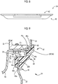
FIG. 5 is a front view of thecover 24 inFIG. 4 as viewed from theengine 10 side.FIG. 6 is a plan view showing thecover 24 inFIG. 4. FIG. 7 is a bottom view showing thecover 24 inFIG. 4 .FIG. 8 is a rear view showing thecover 24 inFIG. 4 .FIG. 9 is a cross-sectional view of thecover 24 inFIG. 4 and is a cross-sectional view taken along line IX-IX ofFIG. 5 .FIG. 10 is a cross-sectional view of thecover 24 inFIG. 4 and is a cross-sectional view taken along line X-X ofFIG. 5 . InFIG. 5 to FIG. 10 , thecover 24 is an elastically deformable elongated elastic body formed by die forming of synthetic rubber such as ethylene propylene diene rubber (EPDM), for example. - The
cover 24 integrally includes an upperend gripping portion 40, a lowerend contact portion 42, and a connectingportion 44. The upperend gripping portion 40 elastically grips theupper end edge 22b of thelower end plate 22. The lowerend contact portion 42 is in contact with the surface on thehousing 12 side of thelower end edge 20f of theupper end plate 20. The connectingportion 44 connects the upperend gripping portion 40 and the lowerend contact portion 42. - The upper
end gripping portion 40 is provided with anelongated groove 40a into which theupper end edge 22b of thelower end plate 22 is fitted, a plurality ofcutouts 40c, and a plurality of engagingprojections 40e. Thecutouts 40c are formed at a plurality of sites in a longitudinal direction of afront wall 40b on theengine 10 side, thefront wall 40b defining thegroove 40a. The engagingprojections 40e are provided to project at a height larger than the width dimension of thegroove 40a on aside wall surface 40d on thehousing 12 side out of a pair of side wall surfaces in thegroove 40a, and are located in thecutouts 40c. - The lower
end contact portion 42 is provided with acover wall 46 that projects upward from an end edge on the clutch 14 side of the connectingportion 44, that is, a firstflat surface 44a (described later), so as to be continuous in the entirety in the longitudinal direction of thecover 24, that is, the width direction of thecover 24 and is in contact with thelower end edge 20f of theupper end plate 20 to cover thelower end edge 20f. - As described above, the
gap 36 is an elongated space between the central portions in the width direction of thelower end edge 20f and theupper end edge 22b, in which a width in the up-and-down direction is relatively large as it goes toward the central portions in the width direction of thelower end edge 20f and theupper end edge 22b and a width in the direction of the rotation axis C is relatively large as it goes toward the central portions in the width direction. Therefore, the upperend gripping portion 40 is provided along the central portion in the width direction of thelower end edge 20f and the lowerend contact portion 42 is provided along the central portion in the width direction of the upperend gripping portion 40. For this reason, the connectingportion 44 connecting the upperend gripping portion 40 and the lowerend contact portion 42 to each other has a first steppedportion 44c and a second steppedportion 44f on theengine 10 side. The first steppedportion 44c is configured of a pair of a firstflat surface 44a and a secondflat surface 44b intersecting substantially perpendicularly with the firstflat surfaces 44a formed substantially at the entirety of the central portion in the width direction. The second steppedportion 44f is configured of a pair of a thirdflat surface 44d and a fourthflat surface 44e intersecting substantially perpendicularly with the thirdflat surface 44d formed at both end portions in the central portion in the width direction. In the mounted state of thecover 24, the firstflat surfaces 44a and the thirdflat surfaces 44d become substantially horizontal surfaces and the secondflat surface 44b and the fourthflat surface 44e become substantially vertical surfaces. - As shown in
FIG. 9 andFIG. 10 , the firstflat surface 44a of the first steppedportion 44c formed on theengine 10 side of thecover 24 has an inclination angle θ1 that is directed downward with respect to a horizontal plane as the firstflat surface 44a is directed toward theengine 10 side. It is desirable that the inclination angle θ1 is as large as possible within the allowable space. However, suitably, the inclination angle θ1 is determined within an angular range of several degrees to ten and several degrees. - As shown in
FIG. 9 andFIG. 10 , the thirdflat surface 44d of the second steppedportion 44f formed on theengine 10 side of thecover 24 also has an inclination angle θ2 that is directed downward with respect to a horizontal plane as the thirdflat surface 44d is directed toward theengine 10 side. It is desirable that the inclination angle θ2 is also as large as possible within the allowable space. However, suitably, the inclination angle θ2 is determined within an angular range of several degrees to ten and several degrees. - Due to the above, foreign matter infiltrating together with traveling wind along arrows shown by the broken lines in
FIG. 2 from between theengine block 10a and theupper end plate 20 is further restrained from staying on the firstflat surface 44a of the first steppedportion 44c and the thirdflat surface 44d of the second steppedportion 44f due to the inclination angle θ1 and the inclination angle θ2 and is actively discharged to the outside. - As described above, the
cover 24 of theend plate 18 for a vehicle of Example 1 covers thegap 36 between thelower end edge 20f of theupper end plate 20 and theupper end edge 22b of thelower end plate 22, whereby infiltration of foreign matter into thehousing 12 is prevented. The first steppedportion 44c having the firstflat surface 44a and the secondflat surface 44b intersecting with the firstflat surface 44a is provided on theengine 10 side of thecover 24. The firstflat surface 44a has the inclination angle θ1 that is directed downward with respect to a horizontal plane as the firstflat surface 44a is directed toward theengine 10 side. Due to the above, foreign matter infiltrating together with traveling wind from between theengine 10 and theend plate 18 is further restrained from staying on the firstflat surface 44a of the first steppedportion 44c and is actively discharged to the outside. - The
cover 24 of theend plate 18 for a vehicle of Example 1 includes the upperend gripping portion 40, the lowerend contact portion 42, and the connectingportion 44. The upperend gripping portion 40 grips theupper end edge 22b of thelower end plate 22. The lowerend contact portion 42 is in contact with the surface on thehousing 12 side of thelower end edge 20f of theupper end plate 20. The connectingportion 44 connects the upperend gripping portion 40 and the lowerend contact portion 42. The first steppedportion 44c is provided on theengine 10 side of the connectingportion 44. Due to the above, thecover 24 can be easily mounted with respect to thegap 36 between thelower end edge 20f of theupper end plate 20 and theupper end edge 22b of thelower end plate 22. - According to the
cover 24 of theend plate 18 for a vehicle of Example 1, thecover 24 is made of elastically deformable synthetic rubber. Thecover 24 integrally includes the upperend gripping portion 40, the lowerend contact portion 42, and the connectingportion 44. Due to the above, it is possible to sufficiently seal thegap 36 between thelower end edge 20f of theupper end plate 20 and theupper end edge 22b of thelower end plate 22, and thecover 24 can be easily mounted with respect to thegap 36. - According to the
cover 24 of theend plate 18 for a vehicle of Example 1, theupper end edge 22b of thelower end plate 22 is linear. The central portion in the lateral width direction of thelower end edge 20f of theupper end plate 20 has the protrudingportion 34 that protrudes toward thehousing 12 side with respect to theupper end edge 22b of thelower end plate 22. Thegap 36 is located in an elongated shape between theupper end edge 22b of thelower end plate 22 and the protrudingportion 34 of thelower end edge 20f of theupper end plate 20, the protrudingportion 34 being located on thehousing 12 side above theupper end edge 22b of thelower end plate 22. Thecover 24 has an elongated shape that closes thegap 36 that is located in an elongated shape. Due to the above, interference between thelower end plate 22 and thefastening bolts 32 of theoil pan 28 to theengine block 10a is further avoided. - According to the
cover 24 of theend plate 18 for a vehicle of Example 1, the second steppedportion 44f is provided at a portion of thecover 24, the portion being located between theupper end edge 22b of thelower end plate 22 and the protrudingportion 34 of thelower end edge 20f of theupper end plate 20. The second steppedportion 44f is provided further on theengine 10 side than the first steppedportion 44c is. The second steppedportion 44f has the thirdflat surface 44d and the fourthflat surface 44e intersecting with the thirdflat surface 44d. The thirdflat surface 44d has the inclination angle θ2 that is directed downward with respect to a horizontal plane as the thirdflat surface 44d is directed toward theengine 10 side. Due to the above, foreign matter infiltrating together with traveling wind from between theengine 10 and theend plate 18 is further restrained from staying on the thirdflat surface 44d of the second steppedportion 44f and is actively discharged to the outside. - According to the
cover 24 of theend plate 18 for a vehicle of Example 1, the upperend gripping portion 40 has thelinear groove 40a into which theupper end edge 22b of thelower end plate 22 is fitted. The lowerend contact portion 42 has thecover wall 46 that protrudes upward from the firstflat surface 44a and is in contact with thelower end edge 20f of theupper end plate 20 to cover thelower end edge 20f. Due to the above, the space between theupper end edge 22b of thelower end plate 22 and thelower end edge 20f of theupper end plate 20 is suitably blocked. - According to the
cover 24 of theend plate 18 for a vehicle of Example 1, thecover 24 has thecutouts 40c at a plurality of sites in the longitudinal direction of thefront wall 40b on theengine 10 side, thefront wall 40b defining thegroove 40a. The engagingprojections 40e that are located in thecutouts 40c are provided to project at a height larger than the width dimension of thegroove 40a on the side wall surface on thehousing 12 side out of the side wall surfaces facing each other in the groove. The engagingrecesses 22c with which the engagingprojections 40e are engaged are provided in theupper end edge 22b of thelower end plate 22. Due to the above, when thecover 24 has been mounted on theupper end edge 22b of thelower end plate 22, thecover 24 is prevented from coming out from thelower end plate 22 due to the engagement of the engagingprojections 40e of thecover 24 with the engagingrecesses 22c of thelower end plate 22, and therefore, assembly of thelower end plate 22 to thehousing 12 is facilitated. - Hereinafter, other examples of the invention will be described. In the following description, parts shared by the above-described example are denoted by the same reference numerals and the description thereof is omitted.
-
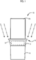
FIG. 11 is a schematic diagram showing the shape of thecover 24 of Example 2 of the invention, which is applied to the vehicle ofFIG. 1 . The firstflat surface 44a of thecover 24 of Example 2 is further provided with an inclination that increases toward the central portion from both ends in the longitudinal direction of the firstflat surface 44a, that is, in the width direction of thelower end plate 22, in addition to the above-described inclination that is directed downward as the firstflat surface 44a is directed toward theengine 10 side. According to Example 2, as shown by a one-dot chain line inFIG. 11 , in a case where traveling wind that is directed toward the middle side from both the outer sides enters between theengine block 10a and theend plate 18, foreign matter is further restrained from staying on the firstflat surface 44a by the traveling wind. -
FIG. 12 is a schematic diagram showing a vehicle, that is, an FF vehicle, to which thecover 24 of an end plate for a vehicle of Example 3 of the invention is applied. In Example 3, as shown by a one-dot chain line, traveling wind that is directed toward the middle side from the outside on one side, which is the front of the vehicle, enters between theengine block 10a and theend plate 18. -
FIG. 13 is a schematic diagram showing the shape of thecover 24 of Example 3, which is applied to the vehicle ofFIG. 12 . The firstflat surface 44a of thecover 24 of Example 3 is further provided with an inclination that increases toward the other end from one end on the windward side and steeply decreases toward the other end portion in the longitudinal direction of the firstflat surface 44a, that is, in the width direction of thelower end plate 22, in addition to the above-described inclination that is directed downward as the firstflat surface 44a is directed toward theengine 10 side. According to Example 3, as shown by a one-dot chain line inFIG. 13 , in a case where traveling wind that is directed toward the other end from one end enters between theengine block 10a and theend plate 18, foreign matter is further restrained from staying on the firstflat surface 44a by the traveling wind. -
FIG. 14 is a schematic diagram showing the shape of thecover 24 of Example 4, which is applied to the vehicle shown inFIG. 12 . In thecover 24 of Example 4, in a case where traveling wind changes direction due to a vehicle-mounted component, as shown by a one-dot chain line inFIG. 14 , in order to make it more difficult for foreign matter to stay on the firstflat surface 44a due to the cyclone effect, the firstflat surface 44a is further provided with an inclination that becomes steeper toward the other end from one end on the windward side and steeply decreases at the other end portion in the longitudinal direction of the firstflat surface 44a, that is, in the width direction of thelower end plate 22, in addition to the above-described inclination that is directed downward as the firstflat surface 44a is directed toward theengine 10 side. - The examples of the invention have been described in detail above based on the drawings. However, the invention is also applicable in other aspects.
- For example, the
cover 24 in the examples described above has an elongated shape according to the shape of theelongated gap 36. However, the shape of thegap 36 and the shape of thecover 24 for covering thegap 36 may be variously changed. In short, a configuration may be made in which the first steppedportion 44c that is configured of the firstflat surface 44a and the secondflat surface 44b intersecting with the firstflat surface 44a is formed on theengine 10 side of thecover 24 and the inclination angle θ1 that is directed downward with respect to a horizontal plane as the firstflat surface 44a is directed toward theengine 10 side is formed on the firstflat surface 44a. - In the
cover 24 in the examples described above, the first steppedportion 44c having the firstflat surface 44a and the second steppedportion 44f having the thirdflat surface 44d are formed on theengine 10 side of thecover 24. However, a configuration may be adopted in which the second steppedportion 44f is not formed and solely the first steppedportion 44c having the firstflat surface 44a is formed. - The above is merely one embodiment, and the invention can be implemented in aspects with various modifications or improvements added thereto based on the knowledge of those skilled in the art.
Claims (7)
- An end plate (18) for a vehicle including an engine (10) and a housing (12), the engine (10) being fastened to the housing (12) through the end plate (18),
the end plate (18) comprising:an upper end plate (20);a lower end plate (22); anda cover (24) that covers a gap (36) between a lower end edge (20f) of the upper end plate (20) and an upper end edge (22b) of the lower end plate (22), the cover including a first stepped portion (44c),wherein the first stepped portion (44c) is provided on an engine side of the cover (24),
the first stepped portion (44c) includes a first flat surface (44a) and a second flat surface (44b) intersecting with the first flat surface (44a); and
the first flat surface (44a) is inclined downward with respect to a horizontal plane as the first flat surface (44a) is directed toward the engine side. - The end plate (18) according to claim 1, wherein:the cover (24) includes an upper end gripping portion (40), a lower end contact portion (42), and a connecting portion (44);the upper end gripping portion (40) grips the upper end edge (22b) of the lower end plate (22);the lower end contact portion (42) is in contact with a surface on a housing side of the lower end edge (20f) of the upper end plate (20);the connecting portion (44) connects the upper end gripping portion (40) and the lower end contact portion (42); andthe first stepped portion (44c) is provided on the engine side of the connecting portion (44).
- The end plate (18) according to claim 2, wherein:the cover (24) is made of elastically deformable synthetic rubber; andthe cover (24) integrally includes the upper end gripping portion (40), the lower end contact portion (42), and the connecting portion (44).
- The end plate (18) according to any one of claims 1 to 3, wherein:the upper end edge (22b) of the lower end plate (22) is linear;a central portion in a lateral width direction of the lower end edge (20f) of the upper end plate (20) has a protruding portion (34) that protrudes toward the housing side with respect to the upper end edge (22b) of the lower end plate (22);the gap (36) is located in an elongated shape between the upper end edge (22b) of the lower end plate (22) and the protruding portion (34), the protruding portion (34) being located on the housing (12) side above the upper end edge (22b) of the lower end plate (22); andthe cover (24) has an elongated shape so as to close the gap (36).
- The end plate (18) according to claim 4, wherein:the cover (24) includes a second stepped portion (44f),the second stepped portion (44f) is located between the upper end edge (22b) of the lower end plate (22) and the protruding portion (34);the second stepped portion (44f) is provided further on the engine side than the first stepped portion (44c) is;the second stepped portion (44f) has a third flat surface (44d) and a fourth flat surface (44e) intersecting with the third flat surface (44d); andthe third flat surface (44d) has an inclination that is directed downward with respect to the horizontal plane as the third flat surface (44d) is directed toward the engine side.
- The end plate (18) according to claim 2, wherein:the upper end gripping portion (40) has a linear groove (40a) into which the upper end edge (22b) of the lower end plate (22) is fitted; andthe lower end contact portion (42) has a cover wall (46) that protrudes upward from the first flat surface (44a) and is in contact with the lower end edge (20f) of the upper end plate (20) to cover the lower end edge (20f).
- The end plate (18) according to claim 6, wherein:the cover (24) includes a front wall (40b) on the engine side of the cover (24),the front wall (40b) has a plurality of cutouts (40c) at a plurality of sites in a longitudinal direction of the front wall (40b), the front wall (40b) defining the groove (40a);a plurality of engaging projections (40e) is located in the cutouts (40c) on a side wall surface (40d) on the housing side out of a pair of side wall surfaces facing each other in the groove (40a);a height of the engaging projections (40e) is larger than a width dimension of the groove (40a); anda plurality of engaging recesses (22c) with which the engaging projections (40e) are engaged is provided at the upper end edge (22b) of the lower end plate (22).
Applications Claiming Priority (1)
| Application Number | Priority Date | Filing Date | Title |
|---|---|---|---|
| JP2017163786A JP6624176B2 (en) | 2017-08-28 | 2017-08-28 | Vehicle end plate cover |
Publications (2)
| Publication Number | Publication Date |
|---|---|
| EP3450719A1 true EP3450719A1 (en) | 2019-03-06 |
| EP3450719B1 EP3450719B1 (en) | 2021-01-27 |
Family
ID=63556122
Family Applications (1)
| Application Number | Title | Priority Date | Filing Date |
|---|---|---|---|
| EP18191251.0A Active EP3450719B1 (en) | 2017-08-28 | 2018-08-28 | End plate for vehicle |
Country Status (7)
| Country | Link |
|---|---|
| US (1) | US10578052B2 (en) |
| EP (1) | EP3450719B1 (en) |
| JP (1) | JP6624176B2 (en) |
| KR (1) | KR20190024756A (en) |
| CN (1) | CN109421819B (en) |
| BR (1) | BR102018069555B1 (en) |
| RU (1) | RU2686598C1 (en) |
Families Citing this family (2)
| Publication number | Priority date | Publication date | Assignee | Title |
|---|---|---|---|---|
| CN111485996B (en) * | 2020-04-21 | 2021-05-11 | 厦门南超机械有限公司 | Single-engine transmission device and system |
| CN116513095B (en) * | 2023-04-14 | 2026-04-24 | 东风柳州汽车有限公司 | A type of car |
Citations (5)
| Publication number | Priority date | Publication date | Assignee | Title |
|---|---|---|---|---|
| GB879219A (en) * | 1959-06-06 | 1961-10-04 | Ferdinand Anton Ernst Porsche | Internal combustion engine |
| GB1129147A (en) * | 1964-10-21 | 1968-10-02 | Hedemora Verkst Er Ab | Improvements in or relating to multiple cylinder piston engines |
| JPH01193069A (en) * | 1988-01-27 | 1989-08-03 | Daihatsu Motor Co Ltd | Connecting device of transmission case for internal combustion engine |
| JPH1047222A (en) * | 1996-08-05 | 1998-02-17 | Daihatsu Motor Co Ltd | Detecting device of ignition timing in internal combustion engine |
| JP2006002743A (en) | 2004-06-21 | 2006-01-05 | Nissan Diesel Motor Co Ltd | Sealing structure between engine end plate and cylinder head |
Family Cites Families (10)
| Publication number | Priority date | Publication date | Assignee | Title |
|---|---|---|---|---|
| US3986413A (en) * | 1975-07-03 | 1976-10-19 | Ford Motor Company | Four-speed automatic coupling transmission |
| JPS606718Y2 (en) * | 1976-06-11 | 1985-03-04 | いすゞ自動車株式会社 | Sound insulation sealing material |
| JPS61155642U (en) * | 1985-03-19 | 1986-09-26 | ||
| JP2001341538A (en) * | 2000-05-31 | 2001-12-11 | Toyota Industries Corp | Housing cover mounting structure for industrial vehicle |
| JP4894274B2 (en) | 2006-01-20 | 2012-03-14 | マツダ株式会社 | Transmission operating mechanism of transmission |
| RU2410556C2 (en) * | 2008-02-21 | 2011-01-27 | Открытое акционерное общество "АВТОВАЗ" | Clutch housing jacket of power unit of wheeled vehicle |
| KR101237929B1 (en) * | 2010-09-03 | 2013-02-28 | 기아자동차주식회사 | Structure of roll rod for vehicle |
| CN201784705U (en) * | 2010-09-17 | 2011-04-06 | 浙江吉利汽车研究院有限公司 | Fixing board for engine hood latch |
| RU2512134C2 (en) * | 2012-07-26 | 2014-04-10 | Федеральное государственное бюджетное образовательное учреждение высшего профессионального образования "Тольяттинский государственный университет" | Automotive integral noise killing module |
| US9103428B2 (en) * | 2013-03-15 | 2015-08-11 | Kawasaki Jukogyo Kabushiki Kaisha | Structure for coupling V-belt type continuously variable transmission with engine |
-
2017
- 2017-08-28 JP JP2017163786A patent/JP6624176B2/en active Active
-
2018
- 2018-08-24 US US16/111,598 patent/US10578052B2/en active Active
- 2018-08-24 RU RU2018130714A patent/RU2686598C1/en active
- 2018-08-27 KR KR1020180100294A patent/KR20190024756A/en not_active Ceased
- 2018-08-27 CN CN201810980409.2A patent/CN109421819B/en active Active
- 2018-08-28 BR BR102018069555-0A patent/BR102018069555B1/en not_active IP Right Cessation
- 2018-08-28 EP EP18191251.0A patent/EP3450719B1/en active Active
Patent Citations (5)
| Publication number | Priority date | Publication date | Assignee | Title |
|---|---|---|---|---|
| GB879219A (en) * | 1959-06-06 | 1961-10-04 | Ferdinand Anton Ernst Porsche | Internal combustion engine |
| GB1129147A (en) * | 1964-10-21 | 1968-10-02 | Hedemora Verkst Er Ab | Improvements in or relating to multiple cylinder piston engines |
| JPH01193069A (en) * | 1988-01-27 | 1989-08-03 | Daihatsu Motor Co Ltd | Connecting device of transmission case for internal combustion engine |
| JPH1047222A (en) * | 1996-08-05 | 1998-02-17 | Daihatsu Motor Co Ltd | Detecting device of ignition timing in internal combustion engine |
| JP2006002743A (en) | 2004-06-21 | 2006-01-05 | Nissan Diesel Motor Co Ltd | Sealing structure between engine end plate and cylinder head |
Also Published As
| Publication number | Publication date |
|---|---|
| US20190063366A1 (en) | 2019-02-28 |
| RU2686598C1 (en) | 2019-04-29 |
| EP3450719B1 (en) | 2021-01-27 |
| JP2019039410A (en) | 2019-03-14 |
| BR102018069555A2 (en) | 2019-04-16 |
| BR102018069555B1 (en) | 2023-04-11 |
| CN109421819B (en) | 2021-11-23 |
| US10578052B2 (en) | 2020-03-03 |
| CN109421819A (en) | 2019-03-05 |
| JP6624176B2 (en) | 2019-12-25 |
| KR20190024756A (en) | 2019-03-08 |
Similar Documents
| Publication | Publication Date | Title |
|---|---|---|
| CN101878381B (en) | Transmission case | |
| CN111834800B (en) | Electrical device | |
| EP3450719B1 (en) | End plate for vehicle | |
| CN117386789B (en) | Lubrication system of vehicle transmission | |
| EP2093395B1 (en) | Oil pan structure for engine | |
| US9610828B2 (en) | Transmitted sound insulating member, and transmitted sound insulating structure including the transmitted sound insulating member | |
| JP7125231B2 (en) | Breather device for vehicle transmission case | |
| JP5829981B2 (en) | Installation structure of electrical component storage case | |
| JP7020275B2 (en) | Vehicle joint cover | |
| US11299029B2 (en) | Power transmission apparatus | |
| JPS6340656Y2 (en) | ||
| KR20170044406A (en) | Anticorrosive gasket for cylinder head | |
| JPH0694842B2 (en) | Engine oil pan structure | |
| KR100569360B1 (en) | Installation structure of speed sensor assembly for automobile | |
| CN210897388U (en) | Battery | |
| EP3647100B1 (en) | Power transmission apparatus | |
| CN224013766U (en) | A front wheel mudguard and an electric vehicle | |
| KR100872641B1 (en) | Automotive Oil Pans | |
| US12326123B2 (en) | Cover member | |
| JP4308789B2 (en) | Splash shield | |
| JPH10205389A (en) | Engine transmission case mounting side structure | |
| JPH02201030A (en) | Cylinder block reinforcing device for engine | |
| EP0152857A2 (en) | Cylinder block of engine | |
| KR970001806B1 (en) | Oil pass structure | |
| US20200196493A1 (en) | Shield cover and assembly body |
Legal Events
| Date | Code | Title | Description |
|---|---|---|---|
| PUAI | Public reference made under article 153(3) epc to a published international application that has entered the european phase |
Free format text: ORIGINAL CODE: 0009012 |
|
| STAA | Information on the status of an ep patent application or granted ep patent |
Free format text: STATUS: REQUEST FOR EXAMINATION WAS MADE |
|
| 17P | Request for examination filed |
Effective date: 20180928 |
|
| AK | Designated contracting states |
Kind code of ref document: A1 Designated state(s): AL AT BE BG CH CY CZ DE DK EE ES FI FR GB GR HR HU IE IS IT LI LT LU LV MC MK MT NL NO PL PT RO RS SE SI SK SM TR |
|
| AX | Request for extension of the european patent |
Extension state: BA ME |
|
| STAA | Information on the status of an ep patent application or granted ep patent |
Free format text: STATUS: EXAMINATION IS IN PROGRESS |
|
| 17Q | First examination report despatched |
Effective date: 20191127 |
|
| GRAP | Despatch of communication of intention to grant a patent |
Free format text: ORIGINAL CODE: EPIDOSNIGR1 |
|
| STAA | Information on the status of an ep patent application or granted ep patent |
Free format text: STATUS: GRANT OF PATENT IS INTENDED |
|
| INTG | Intention to grant announced |
Effective date: 20200826 |
|
| GRAS | Grant fee paid |
Free format text: ORIGINAL CODE: EPIDOSNIGR3 |
|
| GRAA | (expected) grant |
Free format text: ORIGINAL CODE: 0009210 |
|
| STAA | Information on the status of an ep patent application or granted ep patent |
Free format text: STATUS: THE PATENT HAS BEEN GRANTED |
|
| AK | Designated contracting states |
Kind code of ref document: B1 Designated state(s): AL AT BE BG CH CY CZ DE DK EE ES FI FR GB GR HR HU IE IS IT LI LT LU LV MC MK MT NL NO PL PT RO RS SE SI SK SM TR |
|
| REG | Reference to a national code |
Ref country code: GB Ref legal event code: FG4D |
|
| REG | Reference to a national code |
Ref country code: CH Ref legal event code: EP |
|
| REG | Reference to a national code |
Ref country code: AT Ref legal event code: REF Ref document number: 1358540 Country of ref document: AT Kind code of ref document: T Effective date: 20210215 |
|
| REG | Reference to a national code |
Ref country code: IE Ref legal event code: FG4D |
|
| REG | Reference to a national code |
Ref country code: DE Ref legal event code: R096 Ref document number: 602018012219 Country of ref document: DE |
|
| REG | Reference to a national code |
Ref country code: NL Ref legal event code: MP Effective date: 20210127 |
|
| REG | Reference to a national code |
Ref country code: LT Ref legal event code: MG9D |
|
| REG | Reference to a national code |
Ref country code: AT Ref legal event code: MK05 Ref document number: 1358540 Country of ref document: AT Kind code of ref document: T Effective date: 20210127 |
|
| PG25 | Lapsed in a contracting state [announced via postgrant information from national office to epo] |
Ref country code: LT Free format text: LAPSE BECAUSE OF FAILURE TO SUBMIT A TRANSLATION OF THE DESCRIPTION OR TO PAY THE FEE WITHIN THE PRESCRIBED TIME-LIMIT Effective date: 20210127 Ref country code: PT Free format text: LAPSE BECAUSE OF FAILURE TO SUBMIT A TRANSLATION OF THE DESCRIPTION OR TO PAY THE FEE WITHIN THE PRESCRIBED TIME-LIMIT Effective date: 20210527 Ref country code: NO Free format text: LAPSE BECAUSE OF FAILURE TO SUBMIT A TRANSLATION OF THE DESCRIPTION OR TO PAY THE FEE WITHIN THE PRESCRIBED TIME-LIMIT Effective date: 20210427 Ref country code: BG Free format text: LAPSE BECAUSE OF FAILURE TO SUBMIT A TRANSLATION OF THE DESCRIPTION OR TO PAY THE FEE WITHIN THE PRESCRIBED TIME-LIMIT Effective date: 20210427 Ref country code: FI Free format text: LAPSE BECAUSE OF FAILURE TO SUBMIT A TRANSLATION OF THE DESCRIPTION OR TO PAY THE FEE WITHIN THE PRESCRIBED TIME-LIMIT Effective date: 20210127 Ref country code: GR Free format text: LAPSE BECAUSE OF FAILURE TO SUBMIT A TRANSLATION OF THE DESCRIPTION OR TO PAY THE FEE WITHIN THE PRESCRIBED TIME-LIMIT Effective date: 20210428 Ref country code: HR Free format text: LAPSE BECAUSE OF FAILURE TO SUBMIT A TRANSLATION OF THE DESCRIPTION OR TO PAY THE FEE WITHIN THE PRESCRIBED TIME-LIMIT Effective date: 20210127 |
|
| PG25 | Lapsed in a contracting state [announced via postgrant information from national office to epo] |
Ref country code: SE Free format text: LAPSE BECAUSE OF FAILURE TO SUBMIT A TRANSLATION OF THE DESCRIPTION OR TO PAY THE FEE WITHIN THE PRESCRIBED TIME-LIMIT Effective date: 20210127 Ref country code: RS Free format text: LAPSE BECAUSE OF FAILURE TO SUBMIT A TRANSLATION OF THE DESCRIPTION OR TO PAY THE FEE WITHIN THE PRESCRIBED TIME-LIMIT Effective date: 20210127 Ref country code: PL Free format text: LAPSE BECAUSE OF FAILURE TO SUBMIT A TRANSLATION OF THE DESCRIPTION OR TO PAY THE FEE WITHIN THE PRESCRIBED TIME-LIMIT Effective date: 20210127 Ref country code: LV Free format text: LAPSE BECAUSE OF FAILURE TO SUBMIT A TRANSLATION OF THE DESCRIPTION OR TO PAY THE FEE WITHIN THE PRESCRIBED TIME-LIMIT Effective date: 20210127 Ref country code: AT Free format text: LAPSE BECAUSE OF FAILURE TO SUBMIT A TRANSLATION OF THE DESCRIPTION OR TO PAY THE FEE WITHIN THE PRESCRIBED TIME-LIMIT Effective date: 20210127 |
|
| PG25 | Lapsed in a contracting state [announced via postgrant information from national office to epo] |
Ref country code: IS Free format text: LAPSE BECAUSE OF FAILURE TO SUBMIT A TRANSLATION OF THE DESCRIPTION OR TO PAY THE FEE WITHIN THE PRESCRIBED TIME-LIMIT Effective date: 20210527 |
|
| REG | Reference to a national code |
Ref country code: DE Ref legal event code: R097 Ref document number: 602018012219 Country of ref document: DE |
|
| PG25 | Lapsed in a contracting state [announced via postgrant information from national office to epo] |
Ref country code: EE Free format text: LAPSE BECAUSE OF FAILURE TO SUBMIT A TRANSLATION OF THE DESCRIPTION OR TO PAY THE FEE WITHIN THE PRESCRIBED TIME-LIMIT Effective date: 20210127 Ref country code: CZ Free format text: LAPSE BECAUSE OF FAILURE TO SUBMIT A TRANSLATION OF THE DESCRIPTION OR TO PAY THE FEE WITHIN THE PRESCRIBED TIME-LIMIT Effective date: 20210127 Ref country code: SM Free format text: LAPSE BECAUSE OF FAILURE TO SUBMIT A TRANSLATION OF THE DESCRIPTION OR TO PAY THE FEE WITHIN THE PRESCRIBED TIME-LIMIT Effective date: 20210127 |
|
| PG25 | Lapsed in a contracting state [announced via postgrant information from national office to epo] |
Ref country code: DK Free format text: LAPSE BECAUSE OF FAILURE TO SUBMIT A TRANSLATION OF THE DESCRIPTION OR TO PAY THE FEE WITHIN THE PRESCRIBED TIME-LIMIT Effective date: 20210127 Ref country code: SK Free format text: LAPSE BECAUSE OF FAILURE TO SUBMIT A TRANSLATION OF THE DESCRIPTION OR TO PAY THE FEE WITHIN THE PRESCRIBED TIME-LIMIT Effective date: 20210127 Ref country code: RO Free format text: LAPSE BECAUSE OF FAILURE TO SUBMIT A TRANSLATION OF THE DESCRIPTION OR TO PAY THE FEE WITHIN THE PRESCRIBED TIME-LIMIT Effective date: 20210127 |
|
| PLBE | No opposition filed within time limit |
Free format text: ORIGINAL CODE: 0009261 |
|
| STAA | Information on the status of an ep patent application or granted ep patent |
Free format text: STATUS: NO OPPOSITION FILED WITHIN TIME LIMIT |
|
| 26N | No opposition filed |
Effective date: 20211028 |
|
| PG25 | Lapsed in a contracting state [announced via postgrant information from national office to epo] |
Ref country code: AL Free format text: LAPSE BECAUSE OF FAILURE TO SUBMIT A TRANSLATION OF THE DESCRIPTION OR TO PAY THE FEE WITHIN THE PRESCRIBED TIME-LIMIT Effective date: 20210127 Ref country code: ES Free format text: LAPSE BECAUSE OF FAILURE TO SUBMIT A TRANSLATION OF THE DESCRIPTION OR TO PAY THE FEE WITHIN THE PRESCRIBED TIME-LIMIT Effective date: 20210127 |
|
| PG25 | Lapsed in a contracting state [announced via postgrant information from national office to epo] |
Ref country code: SI Free format text: LAPSE BECAUSE OF FAILURE TO SUBMIT A TRANSLATION OF THE DESCRIPTION OR TO PAY THE FEE WITHIN THE PRESCRIBED TIME-LIMIT Effective date: 20210127 |
|
| REG | Reference to a national code |
Ref country code: CH Ref legal event code: PL |
|
| PG25 | Lapsed in a contracting state [announced via postgrant information from national office to epo] |
Ref country code: MC Free format text: LAPSE BECAUSE OF FAILURE TO SUBMIT A TRANSLATION OF THE DESCRIPTION OR TO PAY THE FEE WITHIN THE PRESCRIBED TIME-LIMIT Effective date: 20210127 |
|
| REG | Reference to a national code |
Ref country code: BE Ref legal event code: MM Effective date: 20210831 |
|
| PG25 | Lapsed in a contracting state [announced via postgrant information from national office to epo] |
Ref country code: LI Free format text: LAPSE BECAUSE OF NON-PAYMENT OF DUE FEES Effective date: 20210831 Ref country code: IT Free format text: LAPSE BECAUSE OF FAILURE TO SUBMIT A TRANSLATION OF THE DESCRIPTION OR TO PAY THE FEE WITHIN THE PRESCRIBED TIME-LIMIT Effective date: 20210127 Ref country code: CH Free format text: LAPSE BECAUSE OF NON-PAYMENT OF DUE FEES Effective date: 20210831 |
|
| PG25 | Lapsed in a contracting state [announced via postgrant information from national office to epo] |
Ref country code: IS Free format text: LAPSE BECAUSE OF FAILURE TO SUBMIT A TRANSLATION OF THE DESCRIPTION OR TO PAY THE FEE WITHIN THE PRESCRIBED TIME-LIMIT Effective date: 20210527 Ref country code: LU Free format text: LAPSE BECAUSE OF NON-PAYMENT OF DUE FEES Effective date: 20210828 |
|
| PG25 | Lapsed in a contracting state [announced via postgrant information from national office to epo] |
Ref country code: IE Free format text: LAPSE BECAUSE OF NON-PAYMENT OF DUE FEES Effective date: 20210828 Ref country code: FR Free format text: LAPSE BECAUSE OF NON-PAYMENT OF DUE FEES Effective date: 20210831 Ref country code: BE Free format text: LAPSE BECAUSE OF NON-PAYMENT OF DUE FEES Effective date: 20210831 |
|
| GBPC | Gb: european patent ceased through non-payment of renewal fee |
Effective date: 20220828 |
|
| P01 | Opt-out of the competence of the unified patent court (upc) registered |
Effective date: 20230427 |
|
| PG25 | Lapsed in a contracting state [announced via postgrant information from national office to epo] |
Ref country code: NL Free format text: LAPSE BECAUSE OF NON-PAYMENT OF DUE FEES Effective date: 20210127 Ref country code: CY Free format text: LAPSE BECAUSE OF FAILURE TO SUBMIT A TRANSLATION OF THE DESCRIPTION OR TO PAY THE FEE WITHIN THE PRESCRIBED TIME-LIMIT Effective date: 20210127 |
|
| PG25 | Lapsed in a contracting state [announced via postgrant information from national office to epo] |
Ref country code: HU Free format text: LAPSE BECAUSE OF FAILURE TO SUBMIT A TRANSLATION OF THE DESCRIPTION OR TO PAY THE FEE WITHIN THE PRESCRIBED TIME-LIMIT; INVALID AB INITIO Effective date: 20180828 |
|
| REG | Reference to a national code |
Ref country code: DE Ref legal event code: R084 Ref document number: 602018012219 Country of ref document: DE |
|
| PG25 | Lapsed in a contracting state [announced via postgrant information from national office to epo] |
Ref country code: GB Free format text: LAPSE BECAUSE OF NON-PAYMENT OF DUE FEES Effective date: 20220828 |
|
| PG25 | Lapsed in a contracting state [announced via postgrant information from national office to epo] |
Ref country code: MK Free format text: LAPSE BECAUSE OF FAILURE TO SUBMIT A TRANSLATION OF THE DESCRIPTION OR TO PAY THE FEE WITHIN THE PRESCRIBED TIME-LIMIT Effective date: 20210127 |
|
| PG25 | Lapsed in a contracting state [announced via postgrant information from national office to epo] |
Ref country code: TR Free format text: LAPSE BECAUSE OF FAILURE TO SUBMIT A TRANSLATION OF THE DESCRIPTION OR TO PAY THE FEE WITHIN THE PRESCRIBED TIME-LIMIT Effective date: 20210127 |
|
| PG25 | Lapsed in a contracting state [announced via postgrant information from national office to epo] |
Ref country code: MT Free format text: LAPSE BECAUSE OF FAILURE TO SUBMIT A TRANSLATION OF THE DESCRIPTION OR TO PAY THE FEE WITHIN THE PRESCRIBED TIME-LIMIT Effective date: 20210127 |
|
| PGFP | Annual fee paid to national office [announced via postgrant information from national office to epo] |
Ref country code: DE Payment date: 20250702 Year of fee payment: 8 |