EP3450367A1 - Stacker and processing apparatus - Google Patents
Stacker and processing apparatus Download PDFInfo
- Publication number
- EP3450367A1 EP3450367A1 EP18191626.3A EP18191626A EP3450367A1 EP 3450367 A1 EP3450367 A1 EP 3450367A1 EP 18191626 A EP18191626 A EP 18191626A EP 3450367 A1 EP3450367 A1 EP 3450367A1
- Authority
- EP
- European Patent Office
- Prior art keywords
- medium
- stacker
- support member
- transport roller
- media
- Prior art date
- Legal status (The legal status is an assumption and is not a legal conclusion. Google has not performed a legal analysis and makes no representation as to the accuracy of the status listed.)
- Granted
Links
- 230000007246 mechanism Effects 0.000 claims abstract description 122
- 238000011144 upstream manufacturing Methods 0.000 claims abstract description 44
- 230000001105 regulatory effect Effects 0.000 claims description 31
- 238000000034 method Methods 0.000 claims description 17
- 230000008569 process Effects 0.000 claims description 14
- 230000032258 transport Effects 0.000 description 113
- 230000005540 biological transmission Effects 0.000 description 25
- 210000000078 claw Anatomy 0.000 description 7
- 238000004804 winding Methods 0.000 description 5
- 230000008901 benefit Effects 0.000 description 2
- 239000003086 colorant Substances 0.000 description 2
- 230000009467 reduction Effects 0.000 description 2
- 230000000717 retained effect Effects 0.000 description 2
- 238000005452 bending Methods 0.000 description 1
- 230000008859 change Effects 0.000 description 1
- 230000000694 effects Effects 0.000 description 1
- 239000002184 metal Substances 0.000 description 1
- 230000007704 transition Effects 0.000 description 1
Images


Classifications
-
- B—PERFORMING OPERATIONS; TRANSPORTING
- B65—CONVEYING; PACKING; STORING; HANDLING THIN OR FILAMENTARY MATERIAL
- B65H—HANDLING THIN OR FILAMENTARY MATERIAL, e.g. SHEETS, WEBS, CABLES
- B65H29/00—Delivering or advancing articles from machines; Advancing articles to or into piles
- B65H29/20—Delivering or advancing articles from machines; Advancing articles to or into piles by contact with rotating friction members, e.g. rollers, brushes, or cylinders
- B65H29/22—Delivering or advancing articles from machines; Advancing articles to or into piles by contact with rotating friction members, e.g. rollers, brushes, or cylinders and introducing into a pile
-
- B—PERFORMING OPERATIONS; TRANSPORTING
- B65—CONVEYING; PACKING; STORING; HANDLING THIN OR FILAMENTARY MATERIAL
- B65H—HANDLING THIN OR FILAMENTARY MATERIAL, e.g. SHEETS, WEBS, CABLES
- B65H31/00—Pile receivers
- B65H31/04—Pile receivers with movable end support arranged to recede as pile accumulates
- B65H31/06—Pile receivers with movable end support arranged to recede as pile accumulates the articles being piled on edge
-
- B—PERFORMING OPERATIONS; TRANSPORTING
- B65—CONVEYING; PACKING; STORING; HANDLING THIN OR FILAMENTARY MATERIAL
- B65H—HANDLING THIN OR FILAMENTARY MATERIAL, e.g. SHEETS, WEBS, CABLES
- B65H29/00—Delivering or advancing articles from machines; Advancing articles to or into piles
- B65H29/12—Delivering or advancing articles from machines; Advancing articles to or into piles by means of the nip between two, or between two sets of, moving tapes or bands or rollers
- B65H29/14—Delivering or advancing articles from machines; Advancing articles to or into piles by means of the nip between two, or between two sets of, moving tapes or bands or rollers and introducing into a pile
-
- B—PERFORMING OPERATIONS; TRANSPORTING
- B65—CONVEYING; PACKING; STORING; HANDLING THIN OR FILAMENTARY MATERIAL
- B65H—HANDLING THIN OR FILAMENTARY MATERIAL, e.g. SHEETS, WEBS, CABLES
- B65H31/00—Pile receivers
- B65H31/04—Pile receivers with movable end support arranged to recede as pile accumulates
- B65H31/08—Pile receivers with movable end support arranged to recede as pile accumulates the articles being piled one above another
-
- B—PERFORMING OPERATIONS; TRANSPORTING
- B65—CONVEYING; PACKING; STORING; HANDLING THIN OR FILAMENTARY MATERIAL
- B65H—HANDLING THIN OR FILAMENTARY MATERIAL, e.g. SHEETS, WEBS, CABLES
- B65H31/00—Pile receivers
- B65H31/04—Pile receivers with movable end support arranged to recede as pile accumulates
- B65H31/12—Devices relieving the weight of the pile or permitting or effecting movement of the pile end support during piling
- B65H31/14—Springs
-
- B—PERFORMING OPERATIONS; TRANSPORTING
- B65—CONVEYING; PACKING; STORING; HANDLING THIN OR FILAMENTARY MATERIAL
- B65H—HANDLING THIN OR FILAMENTARY MATERIAL, e.g. SHEETS, WEBS, CABLES
- B65H31/00—Pile receivers
- B65H31/22—Pile receivers removable or interchangeable
-
- B—PERFORMING OPERATIONS; TRANSPORTING
- B65—CONVEYING; PACKING; STORING; HANDLING THIN OR FILAMENTARY MATERIAL
- B65H—HANDLING THIN OR FILAMENTARY MATERIAL, e.g. SHEETS, WEBS, CABLES
- B65H2301/00—Handling processes for sheets or webs
- B65H2301/40—Type of handling process
- B65H2301/42—Piling, depiling, handling piles
- B65H2301/421—Forming a pile
- B65H2301/4214—Forming a pile of articles on edge
- B65H2301/42144—Forming a pile of articles on edge by erecting articles from horizontal transport flushing with the supporting surface of the pile
-
- B—PERFORMING OPERATIONS; TRANSPORTING
- B65—CONVEYING; PACKING; STORING; HANDLING THIN OR FILAMENTARY MATERIAL
- B65H—HANDLING THIN OR FILAMENTARY MATERIAL, e.g. SHEETS, WEBS, CABLES
- B65H2701/00—Handled material; Storage means
- B65H2701/10—Handled articles or webs
- B65H2701/19—Specific article or web
- B65H2701/1914—Cards, e.g. telephone, credit and identity cards
-
- B—PERFORMING OPERATIONS; TRANSPORTING
- B65—CONVEYING; PACKING; STORING; HANDLING THIN OR FILAMENTARY MATERIAL
- B65H—HANDLING THIN OR FILAMENTARY MATERIAL, e.g. SHEETS, WEBS, CABLES
- B65H2701/00—Handled material; Storage means
- B65H2701/10—Handled articles or webs
- B65H2701/19—Specific article or web
- B65H2701/1916—Envelopes and articles of mail
-
- B—PERFORMING OPERATIONS; TRANSPORTING
- B65—CONVEYING; PACKING; STORING; HANDLING THIN OR FILAMENTARY MATERIAL
- B65H—HANDLING THIN OR FILAMENTARY MATERIAL, e.g. SHEETS, WEBS, CABLES
- B65H2801/00—Application field
- B65H2801/03—Image reproduction devices
-
- B—PERFORMING OPERATIONS; TRANSPORTING
- B65—CONVEYING; PACKING; STORING; HANDLING THIN OR FILAMENTARY MATERIAL
- B65H—HANDLING THIN OR FILAMENTARY MATERIAL, e.g. SHEETS, WEBS, CABLES
- B65H2801/00—Application field
- B65H2801/03—Image reproduction devices
- B65H2801/06—Office-type machines, e.g. photocopiers
Definitions
- the present invention relates to a stacker and a processing apparatus.
- the stacker is disposed at an ejection opening of the processing apparatus and causes media to be ejected through the ejection opening to be stacked and placed.
- Examples of such a stacker include those of, for example, JP-A-11-199113 and JP-A-10-194553 .
- These documents describe a structure that includes a support member with which sheets ejected through an ejection opening of a printer are inclined upward and stacked.
- the support member is positioned, instead of being positioned close to the ejection opening, so as to be largely separated from the ejection opening of the printer.
- the position of the support member is fixed.
- a conveyor belt is disposed between the ejection opening of the printer and the support member.
- the conveyor belt is downwardly inclined toward the downstream side in a feeding direction.
- the sheets are substantially horizontally ejected onto the conveyor belt, transported by the conveyor belt to the position of the support member, and stacked so as to be upwardly inclined.
- the support member is fixed at the position largely separated from the ejection opening of a processing apparatus such as a printer instead of being positioned close to the ejection opening of the processing apparatus.
- a processing apparatus such as a printer
- the conveyor is necessary for transportation of the media to the separated position of the support member.
- the entirety of the stacker is increased in size.
- transportation by the conveyor belt is added. This gives rise to a problem in that control of transport operation for stacking becomes complex.
- An advantage of some aspects of the invention is that an increase in size of a stacker can be suppressed while the amount of media to be stacked can be increased.
- a stacker is disposed at an ejection opening of a processing apparatus and causes media ejected through the ejection opening to be stacked and placed on a stacking surface.
- the stacker includes a support member, a receding mechanism, and a position maintaining mechanism.
- the support member is movable toward an upstream side and a downstream side in an ejecting direction, receives each of the media ejected through the ejection opening, and supports the medium in such an orientation that the medium is inclined with an end edge of the medium on the downstream side in the ejecting direction positioned above an end edge of the medium on the upstream side in the ejecting direction and that the end edge of the medium on the upstream side in the ejecting direction abuts the stacking surface.
- the receding mechanism causes the support member to recede toward the downstream side.
- the position maintaining mechanism maintains a position of the support member having been moved by the receding mechanism.
- the support member that supports the media in an upwardly inclined orientation is movable toward the upstream side and the downstream side in the ejection direction.
- the receding mechanism can cause the support member to recede toward the downstream side, and the position maintaining mechanism can maintain the position of the support member having receded by the specified distance, that is the position maintaining mechanism can hold the support member at this position.
- the support member recedes by the specified distance and is kept at the position to which the support member has receded. This can ensure a space to support the next medium.
- the term “maintain the position of the support member” means that the support member is held at the position to which the support member has been moved by the receding mechanism. However, this does not necessarily mean that the support member does not move at all.
- the position of the support member may move at low speed as long as a technical significance of the above-described term “maintain the position" (a state in which operation for supporting the next medium in the standing orientation can be performed at the support space for the media obtained by the receding) is substantially satisfied.
- the position maintaining mechanism include a pulling mechanism that applies to the support member a pulling force to pull toward the upstream side and a suppressing mechanism that suppresses the pulling force at a position to which the support member has been caused to recede by a specified distance by the receding mechanism.
- the term “suppresses the pulling force” means canceling of the pulling force so as to maintain the support member at the position or reduction of the pulling force.
- the position maintaining mechanism that maintains the position of the support member having been moved by the receding mechanism can be realized with a simple structure.
- the receding mechanism apply a moving force to move against a frictional force caused by frictional resistance with the stacking surface which serves as a surface sliding against the support member.
- the position maintaining mechanism maintains the position of the support member by utilizing the frictional resistance.
- the position of the support member having been moved by the receding mechanism is maintained at the position by utilizing the frictional force of the sliding surface. Accordingly, the position maintaining mechanism can be realized with a simple structure in which the constant force spring or the like is not used.
- stacker further include a transport roller that receives the medium ejected through the ejection opening and that transports the medium toward the downstream side.
- the transport roller is driven by transmitting motive power with which the processing apparatus ejects the medium.
- the stacker includes the transport roller that transports toward the downstream side the medium ejected through the ejection opening.
- the transport roller By setting the transport roller as a base point of a medium transport path of the stacker, the design of the medium transport path and transport control can be simply performed.
- the transport roller is driven by utilizing the motive power of the processing apparatus for the ejection. Accordingly, no dedicated motive power source is required.
- the transport roller be driven by transmitting the motive power from a rotation shaft of an ejection roller positioned at a most downstream portion of the processing apparatus in the ejecting direction.
- the motive power is transmitted to the transport roller from the rotation shaft of the ejection roller positioned at the most downstream portion near the ejection opening on the processing apparatus side. This allows the motive power transmission structure to be realized with a simple structure.
- the receding mechanism include an advancing/retreating member provided on a rotation shaft of the transport roller.
- the advancing/retreating member repeatedly performs, linked with the rotation of the rotation shaft of the transport roller, pushing of the support member and retreating from the support member.
- the advancing/retreating member provided on the rotation shaft of the transport roller repeatedly performs, linked with the rotation of the rotation shaft of the transport roller, pushing of the support member and retreating from the support member.
- the receding of the support member by the specified distance can be performed by the "pushing" with the advancing/retreating member, and the operation to ensure the support space for the medium through the receding of the support member can be performed by the "retreating".
- the receding mechanism include a first cam member provided on the rotation shaft of the transport roller.
- the first cam member causes, linked with the rotation of the rotation shaft of the transport roller, the advancing/retreating member to perform the pushing and the retreating.
- the pushing and the retreating by the advancing/retreating member can be realized with a simple structure by using the first cam member provided on the rotation shaft of the transport roller.
- the stacker further include a nipping member that, together with the transport roller, nips the medium therebetween so as to transmit a transport force of the transport roller to the medium while the medium is being nipped.
- the nipping is released when the advancing/retreating member performs the pushing.
- the nipping performed by the nipping member paired with the transport roller so as to transmit the transport force to the medium is released while the advancing/retreating member is performing the pushing.
- the transport force is not transmitted to the medium while the pushing is being performed. Accordingly, during the operation to ensure the support space for the medium through the receding, the medium is not fed into the support space by the "pushing" of the advancing/retreating member. This can reduce the likelihood of jamming or creasing of the medium.
- the nipping member be able to be displaced between a position at which the nipping member together with the transport roller performs the nipping and a position at which the nipping is released, and a second cam member be provided on the rotation shaft of the transport roller.
- the second cam member causes, linked with the rotation of the rotation shaft of the transport roller, the nipping member to be displaced.
- the second cam member provided on the rotation shaft of the transport roller causes the nipping member to be displaced between the position at which the nipping member performs the nipping and the position at which the nipping is released. Accordingly, the nipping can be released with a simple structure.
- the pulling mechanism be a constant force spring
- the suppressing mechanism be a regulating portion that regulates rotation of the constant force spring in a direction in which the constant force spring is wound.
- the position maintaining mechanism can be easily realized with the constant force spring.
- the stacker be a unitized device that is removably mountable in the processing apparatus.
- the stacker is the unitized device that is removably mountable in the processing apparatus. Accordingly, stacking with the stacker and stacking performed by the processing apparatus itself without the stacker can be switched.
- the motive power on the processing apparatus side can be easily utilized with the structure in which the unitized stacker can be set in alignment with the ejection opening of the processing apparatus.
- a processing apparatus includes a processing unit, an ejection mechanism, and a stacker unit.
- the processing unit performs a specified process on media.
- the ejection mechanism ejects through an ejection opening the media transported thereto through the processing unit.
- the stacker unit receives the media ejected through the ejection opening and stacks the media.
- the stacker unit is any one form of the above-described stacker.
- the processing apparatus can obtain the effects produced by any one form of the stacker.
- a multi-functional ink jet printer that includes stacking-type medium cassettes, a medium feed tray for manual feeding, and a medium ejection tray for manual ejection as an example of a processing apparatus according to an embodiment of the invention
- the structure of the processing apparatus according to the embodiment of the invention, the structure of a stacker according to the embodiment of the invention used for the medium ejection tray of the processing apparatus, and forms of operation of the processing apparatus mainly including operation of the stacker will be described in detail below with reference to the accompanying drawings.
- the ejection unit includes the medium ejection tray for which the stacker according to the embodiment of the invention is used and members around the medium ejection tray.
- the structure of the stacker according to the embodiment of the invention used for the medium ejection tray is specifically described.
- the forms of operation of the processing apparatus according to the embodiment of the invention mainly including operation of the stacker are described.
- reference is made to the structures of other embodiments that are partially different from the structure of the embodiment are referred to.
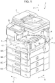
- a processing apparatus 1 illustrated in the drawings is a multi-functional ink jet printer that includes a scanner unit 3, medium cassettes 5A to 5D, a medium feed tray 7, and a medium ejection tray 8.
- the scanner unit 3 is disposed in an upper portion of an apparatus main body 2.
- four medium cassettes 5A to 5D are disposed in a lower portion of the apparatus main body 2.
- the medium cassettes 5A to 5D are stacked one on top of another.
- the medium feed tray 7 is disposed in, for example, a right side surface of the apparatus main body 2.
- the medium feed tray 7 is used for manual feeding.
- the medium ejection tray 8 is disposed in, for example, a left side surface of the apparatus main body 2.
- the medium ejection tray 8 is used for manual ejection.
- a display/operating panel 9 is provided, for example, on the left-hand side of an upper portion of the apparatus main body 2 as viewed from the front.
- the display/operating panel 9 is for setting various items and performing operations of the processing apparatus 1.
- a comparatively large space A is formed, for example, on the righthand side of the display/operating panel 9 as viewed from the front.
- Media P which have been fed from the medium cassettes 5A to 5D and on which processes have been performed are received in the space A in a face placement orientation.
- the bottom of the space A is an ejection stacker 11.
- a standard-equipment medium cassette 5A is provided uppermost in the stacked medium cassettes 5A to 5D in a lower portion of the apparatus main body 2.
- Three additional medium cassettes 5B to 5D are provided below the medium cassette 5A.
- the medium feed tray 7 of, for example, an opening/closing lid type for manual feeding is provided in, for example, the right side surface of the apparatus main body 2 as viewed from the front.
- the medium ejection tray 8 of, for example, an opening/closing lid type for manual ejection is provided in, for example, the left side surface of the apparatus main body 2 as viewed from the front.
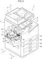
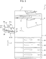
- the apparatus main body 2 includes therein a processing unit 13, a transport unit 17, an ejection unit 10, and a controller 19.
- the processing unit 13 performs specified printing processes by ejecting droplets of colors (for example, four colors including cyan (C), magenta (M), yellow (Y), and black (K)) to each of the media P having been fed from one of the medium cassettes 5A to 5D or the medium feed tray 7.
- the transport unit 17 transports the media P toward a processing region 15 of the processing unit 13.
- the ejection unit 10 ejects to the outside of the apparatus main body 2 the media P which have been fed from the medium feed tray 7 and on which processes have been performed.
- the controller 19 controls various operations of the processing unit 13, the transport unit 17, and the ejection unit 10, items displayed in the display/operating panel 9, and so forth by receiving information from the display/operating panel 9 and external devices such as a personal computer (PC) and the like.
- PC personal computer
- a so-called line-head-type processing head is provided.
- the line-head-type processing head performs a process (for example, recording) in a width direction X of each of the media P entirely at a time. This process is performed at a fixed feed pitch.
- the width direction X intersects a direction Y in which the media P are transported.
- serial-head-type processing head is mounted on a carriage (not illustrated) and is reciprocated in the width direction X so as to perform a specified process.
- a transport unit into which, for example, the following components are unitized is used as the transport unit 17: nipping transport rollers that transport toward the processing region 15 or the ejection unit 10, which will be described later, the media P having been fed by feeding rollers (not illustrated); motors that drive these components; gear trains, belts, and so forth; guide rollers and guide plates that guide transportation of the media P; and a reverse mechanism that reverses the transport direction.
- the processing apparatus 1 is basically structured with the processing unit 13, an ejection mechanism 18 ( Fig. 9 ), and a stacker 21 (stacker unit) included therein.
- the processing unit 13 performs specified processes on the media P.
- the ejection mechanism 18 ejects through an ejection opening 20 the media transported thereto through the processing unit 13.
- the stacker 21, which will be described later, receives media P ejected through the ejection opening 20 and stacks the received media P one on top of another.
- the unitized stacker 21 removably disposed in the ejection unit 10 of the processing apparatus 1 is used.
- face placement orientation which may alternatively be referred to as “lying orientation” refers to an orientation in which the media P are stacked such that the faces of the media P are (preferably horizontally) placed along a placement surface 23 of the medium ejection tray 8
- edge placement orientation which may alternatively be referred to as “standing orientation” refers to an orientation in which the media P are stacked such that the edges of a plurality of the media P are in contact with a stacking surface 22 of the stacker 21, which will be described later, that is, the media P stand erect.
- the ejection unit 10 includes the ejection opening 20, the medium ejection tray 8, and ejection rollers 18 ( Fig. 9 ).
- the ejection opening 20 is formed in, for example, the left side surface of the apparatus main body 2.
- the medium ejection tray 8 openably closes the ejection opening 20.
- the ejection rollers 18 are provided on the apparatus main body 2 side so as to face the ejection opening 20 and serve as elements of the ejection mechanism.
- the ejection opening 20 has a rectangular window shape elongated in the width direction X.
- the ejection opening 20 has a recessed space extending slightly inward from the side surface of the apparatus main body 2.
- the medium ejection tray 8 has pivot supports (not illustrated) disposed at lower portions of inner surfaces at both end portions in the width direction X in the recessed space.
- the medium ejection tray 8 is pivotable about the pivot supports between a position where the medium ejection tray 8 is in a closed state in which the medium ejection tray 8 closes the ejection opening 20 formed in the side surface of the apparatus main body 2 while being parallel to this side surface and a position where the medium ejection tray 8 is in an open state in which the medium ejection tray 8 is opened so as to expose the ejection opening 20 while the medium ejection tray 8 intersects this side surface at an angle ⁇ ( Fig. 15 ).
- the angle ⁇ at which the medium ejection tray 8 intersects the side surface is set to, for example, about 80°. Due to this setting, the placement surface 23 of the medium ejection tray 8 extending toward the downstream side in a direction Y in which the media P is ejected becomes an upward inclination of about 10°.
- a handle (not illustrated) is provided in a front surface of the medium ejection tray 8. A user holds this handle to cause the medium ejection tray 8 to pivot.
- a rear surface of the medium ejection tray 8 is the placement surface 23 on which the media P is placed in the face placement orientation (lying orientation).
- An extension tray 29 is connected to the medium ejection tray 8 at a distal end portion of the medium ejection tray 8. The extension tray 29 can be drawn out in the direction Y in which the media P is ejected and retracted in the opposite direction.
- the placement surface 23 of the medium ejection tray 8 has, for example, a recess, and a base frame 37 of the stacker 21, which will be described later, has, for example, a projection at its bottom surface. With this structure, positioning in a planar direction XY parallel to the placement surface 23 is performed by fitting the projection into the recess.
- Motive power is transmitted from, for example, the transport unit 17 in the apparatus main body 2 to the shaft 25 so as to rotate the shaft 25 in an ejection direction Y in which the medium P is ejected.
- the stacker 21 which will be described next, is not particularly provided with a motive power source.
- the stacker 21 performs specified operations by receiving motive power from the ejection rollers 18 rotated together with the shaft 25.
- the stacker 21 is provided at the ejection opening 20 of the processing apparatus 1 and stacks the media P ejected through the ejection opening 20.
- the media P are stacked in the direction Y in which the media P is ejected.
- the media P stacked are in the edge placement orientation (standing orientation).
- the stacker 21 basically includes a support member 53, a receding mechanism 111, and a position maintaining mechanism 56.
- the support member 53 is movable toward the upstream side and the downstream side in the ejecting direction Y, receives the media P ejected through the ejection opening 20, and supports the media P such that the media P are inclined upward at an inclination angle ⁇ ( Fig. 15 ).
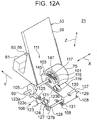
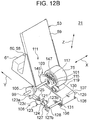
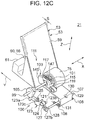
- the receding mechanism 111 ( Figs. 7 to 12D ) causes the support member 53 to recede toward the downstream side in the ejecting direction Y.
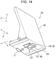
- the position maintaining mechanism 56 ( Figs. 6 and 9 to 14 ) that maintains the position of the support member 53 having been moved by the receding mechanism 111.
- the position maintaining mechanism 56 includes a pulling mechanism 57 and a suppressing mechanism 58.
- the pulling mechanism 57 causes a force F ( Fig. 15 ) that pulls toward the upstream side in the ejecting direction Y to act on the support member 53.
- the suppressing mechanism 58 ( Fig. 14 ) suppresses the pulling force F at a position to which the support member 53 has been caused to recede by the receding mechanism 111 by a specified distance S ( Figs. 12C , 15 , and 17C ).
- the term “suppresses the pulling force F” means both the following operations: maintaining the support member 53 at the position by causing a force the magnitude of which is the same as the pulling force F and which is oppositely directed to the pulling force F to act so as to cancel the pulling force F; and causing a force the magnitude of which is not the same as the pulling force F and which is oppositely directed to the pulling force F to act so as to reduce the pulling force F.
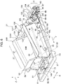
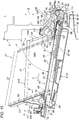
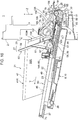
- the stacker 21 includes the base frame 37 having a substantially rectangular plate shape. Various components to be described below are provided on an upper surface of the base frame 37.
- a pair of side guide portions 41L and 41R are provided near respective side end portions of the base frame 37 in the width direction X.
- the side guide portions 41L and 41R guide the respective side edges of the media P, the side edges located at the sides in the X direction.
- the media P is to be stacked in the edge placement orientation (standing orientation).
- the side guide portions 41L and 41R can be moved toward/separated from each other over a specified stroke in the width direction X.
- the distance between the left and right side guide portions 41L and 41R is adjusted within the length of elongated holes 43 formed as examples in the base frame 37.
- the side guide portions 41L and 41R are fixed at respective positions by tightening fixing screws 45 as examples having knobs at the heads thereof.
- Two fixing screws 45 are provided at each side in the width direction X, that is, a total of four fixing screws 45 are provided.
- the side guide portions 41L and 41R are formed by, for example, bending thin metal sheets into a U shape.
- Upper bent portions that project outward serve as handle portions 47 to be held by hands for operation when adjusting the distance between the side guide portions 41L and 41R.
- lower bent portions serve as base plates 49 in contact with the upper surface of the base frame 37 so as to hold the side guide portions 41L and 41R in a standing position.
- the length of the side guide portions 41L and 41R is slightly smaller than the length of the base frame 37.
- a member of a transportation system which will be described later, the receding mechanism 111 that cooperates with the transport system member, and elements of a nip release mechanism 106 ( Figs. 11 and 12A to 12D), which will be described later, are disposed in a space upstream of the side guide portions 41L and 41R in the ejecting direction Y.
- the transport system member reorients the ejected media P from the face placement orientation (lying orientation) so that the media P assume the edge placement orientation (standing orientation) and feeds the media P to a stacking region 27 of the stacker 21.
- a guide scale 51 ( Fig. 6 ) and an accommodating space are formed.
- the guide scale 51 serves as a guide when the distance between the side guide portions 41L and 41R is adjusted.
- the accommodating space accommodates the support member 53 having moved to a maximum stacking position. The support member 53 will be described later.
- guide scales 51 are also formed beside upstream end portions of the side guide portions 41L and 41R in the ejecting direction Y. Spaces obtained by cutting parts of the base plates 49 are utilized for these guide scales 51.
- the height of guide side plates 55 that connect the handle portions 47 and the base plates 49 of the side guide portions 41L and 41R to one another is large on the upstream side and small in the downstream side in the ejecting direction Y. That is, the side guide portions 41L and 41R are set such that the guiding distance is larger on the upstream side where the media P ejected from the processing apparatus 1 are placed on the stacker 21 than on the downstream side where media P are removed from the stacker 21.
- the support member 53 includes a support plate 59 and a slide block 61.
- the support plate 59 supports the media P in such an orientation that the media P are inclined toward the downstream side with upper portions thereof further in the ejecting direction Y than lower portions thereof.
- the slide block 61 supports the support plate 59 such that the support plate 59 is movable toward the upstream side and the downstream side in the ejecting direction Y.
- the support plate 59 is inclined at, for example, an inclination angle ⁇ ( Fig. 15 ) of about 60° relative to the stacking surface 22 of the stacker 21.
- the stacking surface 22 is part of the upper surface of the base frame 37, the left and right sides of which are defined by the side guide portions 41L and 41R and the surface of which on the downstream side in the ejecting direction Y is defined by the support plate 59.
- the slide block 61 includes a projection 65, a winding mechanism 67 ( Figs. 6 , 13 , and 14 ), a regulating portion 58, a regulation release lever 60 ( Figs. 6 , 15 , and 16 ), and so forth.
- the projection 65 ( Fig. 15 ) is provided in a lower surface of the slide block 61 and engaged with a guide hole 63 ( Fig. 7 ) extending in the ejecting direction Y at the center of the base frame 37 in the width direction X.
- the winding mechanism 67 ( Figs. 6 , 13 , and 14 ), a regulating portion 58, a regulation release lever 60 ( Figs. 6 , 15 , and 16 ), and so forth.
- the projection 65 ( Fig. 15 ) is provided in a lower surface of the slide block 61 and engaged with a guide hole 63 ( Fig. 7 ) extending in the ejecting direction Y at the center of the base frame 37 in the width direction
- the slide block 61 is provided in the slide block 61 and comprises a constant force spring 57 (denoted by the same reference sign as that of the pulling mechanism) included in the pulling mechanism 57.
- the regulating portion 58 ( Fig. 14 ) is included in the suppressing mechanism.
- the regulation release lever 60 ( Figs. 6 , 15 , and 16 ) is operated in order to release a stated regulation by the regulating portion 58.
- the stacker 21 moves the media P to the stacking region 27 by driving the transport system member, which is described below, by using the rotation of the ejection rollers 18 of the processing apparatus 1 as a motive power source.
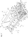
- a transport roller 75 (for example, Fig. 7 ) is provided.
- the transport roller 75 applies a feeding force to the media P ejected by the ejection rollers 18 to the outside of the apparatus main body 2.
- the transport roller 75 is attached to a rotation shaft 99 supported by a support frame 137 provided in a space on the upstream side of the base frame 37 in the ejecting direction Y.
- the transport roller 75 is located, for example, at the center in the stacker 21 in the width direction X.
- the transport roller 75 paired with a nipping member 107 (for example, Fig. 8 ) provided below the transport roller 75 nips the supplied media P, thereby applying the feeding force to the media P.
- the nipping member 107 includes a plate-shaped member that substantially horizontally extends toward the downstream side in the ejecting direction Y from a bent portion where the nipping member 107 is bent downward.
- the bent portion is disposed at an end portion on the upstream side in the ejecting direction Y where a pivot shaft 129 is integrally fixed with a fixing screw 130.
- a nipping roller 109 ( Figs. 15 to 17D ) is provided at an end portion of the nipping member 107 on the downstream side in the ejecting direction Y. This end portion is a pivot free end of the nipping member 107. The nipping roller 109 is brought into contact with the transport roller 75 for nipping operation.
- retaining claws 108 are provided at a lower end of the downwardly bent portion on the upstream side of the nipping member 107.
- the retaining claws 108 outwardly project to the left and right in the width direction X.
- a spring 131 ( Figs. 10 to 12D ) is attached to each of the retaining claws 108. The spring 131 performs pushing so that the pivot free end of the nipping member 107 is constantly displaced toward the transport roller 75.
- the nipping roller 109 is a preferable structure for smooth transportation of the media P. However, the nipping roller 109 may be omitted when a sufficient feeding force can be obtained only by a contact of the transport roller 75 with the pivot free end of the nipping member 107.
- the power transmission unit 77 transmits the motive power of the ejection rollers 18 to the transport roller 75.
- the power transmission unit 77 utilizes, for example, ejection rollers 18L and 18R (simply denoted as "18" in some cases) that are a second ejection roller 18 from the left end and a second ejection roller 18 from the right end in the width direction X, respectively, to transmit the motive power ( Fig. 9 ).
- the power transmission unit 77 includes, for example, transmission rollers 79L and 79R, first transmission gears 83, intermediate gears 85, a second transmission gear 89, an input pulley 93, and an output pulley 97.
- the transmission rollers 79L and 79R (simply denoted as "79" in some cases) abut the ejection rollers 18L and 18R, thereby the rotation is first transmitted to the transmission rollers 79L and 79R.
- the first transmission gears 83 are provided on the shaft 81, on which the transmission rollers 79L and 79R are provided, and rotated together with the transmission rollers 79L and 79R.
- the intermediate gears 85 are engaged with the first transmission gears 83 and rotated about a shaft 87.
- the second transmission gear 89 is engaged with one of the intermediate gears 85.
- the input pulley 93 is provided on a shaft 91, on which the second transmission gear 89 is provided, and rotated together with the second transmission gear 89.
- the rotation of the input pulley 93 is transmitted via a toothed timing belt 95 to the output pulley 97 provided on the rotation shaft 99, on which the transport roller 75 is provided.
- the output pulley 97 is rotated together with the transport roller 75.
- the transport roller 75 is rotated in the opposite direction to the rotation direction of the ejection rollers 18 and rotated at the same speed as the rotation speed of the ejection rollers 18.
- the media P are smoothly moved and transported to the stacker 21.
- lifting-off suppressing members 133L and 133R (simply denoted as "133" in some cases) are described.
- the lifting-off suppressing members 133L and 133R improve performance with which the media P is introduced by suppressing lifting-off of the media P caused by curl or the like of the media P occurring when the media P is moved to the stacker 21.
- end edges of the guide side plates 55L and 55R (simply denoted as "55" in some cases) of the side guide portions 41L and 41R on the upstream side in the ejecting direction Y are inclined at the substantially same angle as the angle at which the support plate 59 of the support member 53 is inclined.
- the lifting-off suppressing members 133L and 133R are provided inside the inclined end edges.
- Each of the lifting-off suppressing members 133L and 133R has a substantially L shape in side view.
- the lifting-off suppressing members 133L and 133R include inclined portions 134 and horizontal portions 135.
- the inclined portions 134 are provided along the end edges of the guide side plates 55L and 55R of the side guide portions 41L and 41R on the upstream side in the ejecting direction Y.
- the horizontal portions 135 extend from the lower ends of the inclined portions 134 toward the upstream side in the ejecting direction Y so as to be continuous with the inclined portions 134 and parallel to the upper surface of the base frame 37. Furthermore, end portions of the horizontal portions 135 on the upstream side in the ejecting direction Y slightly outwardly project to the left and right in the width direction X so as to have a large width.
- entrance guides 136 having, for example, a U-shaped section are provided of portions functioning as slopes that guide the media P ejected to the end portions by the ejection rollers 18 so that misalignment in the width direction X is corrected and the media P comes to the center in the width direction X.
- gaps having specified sizes are formed between each of the side edges of the medium P in the width direction X moved to the stacker 21 and transported and a rear surface of a corresponding one of the inclined portions 134 and between these edge of the medium P and a lower surface of a corresponding one of the horizontal portions 135.
- Lifting-off and inclination of the medium P are regulated within the sizes of these gaps. Accordingly, even when a force acts to displace an upper portion of the medium P having been transitioned to the edge placement orientation (standing orientation) toward the upstream side in the ejecting direction Y, the medium P is brought into contact with the rear surface of the inclined portion 134, and the medium P that is lifted off or inclined larger than the sizes of the above-described gaps is restored to the original position. Thus, smooth transportation of the media P on the stacking surface 22 is maintained.
- the support frame 137 has a sub-frame 141 at a top plate portion thereof.
- the sub-frame 141 extends downward and has a substantially L shape in section ( Figs. 8 and 9 ).
- the sub-frame 141 has a side wall portion 143 perpendicular to the upper surface of the base frame 37 and a bottom plate portion parallel to the upper surface of the base frame 37.
- the bottom plate portion serves as a suppressing plate 139 that suppresses lifting-off or bulging in the central portion of the medium P in the width direction X being moved to the stacker 21.
- the position where the suppressing plate 139 is provided is set upstream of the transport roller 75 in the ejecting direction Y.
- An upstream end portion of the suppressing plate 139 is inclined slightly upward. This suppresses catching of the medium P by the suppressing plate 139 when the medium P is supplied with a large lifting-off formed therein.
- the horizontal portions 135 of the lifting-off suppressing members 133L and 133R, the suppressing plate 139, and the inclined portions 134 are separately defined as first lifting-off suppressors, a second lifting-off suppressor, and a third lifting-off suppressor, respectively.
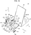
- the receding mechanism 111 includes an advancing/retreating member 103 provided on the rotation shaft 99 of the transport roller 75.
- the advancing/retreating member 103 repeatedly performs, linked with the rotation of the rotation shaft 99 of the transport roller 75, pushing of the support member 53 and retreating from the support member 53.
- the receding mechanism 111 includes a first cam member 101 made integral with the rotation shaft 99 of the transport roller 75.
- the first cam member 101 causes the advancing/retreating member 103 to perform, linked with the rotation of the rotation shaft 99 of the transport roller 75, the pushing and the retreating.
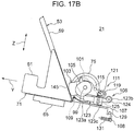
- the advancing/retreating member 103 has a flat plate shape elongated in the ejecting direction Y as illustrated in Figs. 10 and 11 .
- An end portion on the downstream side of the advancing/retreating member 103 in the ejecting direction Y has an arc shape ( Figs. 17A to 17D ) having a large radius of curvature.
- This end portion serves as a pushing actuator 145 that abuts the support plate 59 of the support member 53 so as to cause the support member 53 to recede by a specified distance S (for example, 1 to 10 mm; Figs. 12C and 17C to be referred to later).
- the advancing/retreating member 103 has a first fitting elongated hole 117 ( Fig. 11 ) and a second fitting elongated hole 119 ( Fig. 10 ).
- the first fitting elongated hole 117 is fitted onto the rotation shaft 99 of the transport roller 75.
- the second fitting elongated hole 119 is fitted onto a guide shaft 121 attached to the side wall portion 143 ( Fig. 9 ) of the sub-frame 141.
- the advancing/retreating member 103 can repeatedly perform the above-described pushing and retreating within the length of these two elongated holes 117 and 119.
- a first shift pin 113 and a second shift pin 115 spaced apart from each other by a specified distance in the ejecting direction Y are provided on a surface of the advancing/retreating member 103 on the transport roller 75 side.
- the first shift pin 113 and the second shift pin 115 project toward the transport roller 75.
- the first shift pin 113 abuts the first cam member 101 so as to cause the advancing/retreating member 103 to move in the pushing direction with respect to the support member 53.
- the second shift pin 115 abuts the first cam member 101 so as to cause the advancing/retreating member 103 to move in the retreating direction.
- a spring denoted by a reference sign 147 pulls the first shift pin 113 of the advancing/retreating member 103 toward the first cam member 101 so as to cause the first shift pin 113 to abut the first cam member 101.
- the position maintaining mechanism 56 includes the pulling mechanism 57 and the suppressing mechanism 58.
- the pulling mechanism 57 includes, for example, the constant force spring 57 formed by winding an elongated plate spring to have a spiral shape.
- An unwound end 69 of the constant force spring 57 is fixed by a fixing screw (not illustrated) or the like to a portion of the base frame 37 near a position where the transport roller 75 is provided ( Figs. 6 and 15 ). Accordingly, a force to move the support member 53 toward the upstream side in the ejecting direction Y is generated by utilizing a force of the constant force spring 57 for restoration of the original shape.
- the suppressing mechanism 58 includes the regulating portion 58 that includes, for example, a wedge-shaped member regulating the rotation of the constant force spring 57 in the winding direction.
- the regulating portion 58 includes, for example, a wedge-shaped member regulating the rotation of the constant force spring 57 in the winding direction.
- another member that similarly acts such as a one-way roller can be used as the regulating portion 58.
- the regulation release lever 60 that switches the state of the regulating portion 58 between a regulating state and a regulation release state is provided in the support member 53.
- the regulation release lever 60 is connected to the regulating portion 58 at an end on the upstream side in the ejecting direction Y and provided with an operating portion 149 at an end on the downstream side in the ejecting direction Y.
- the operating portion 149 of the regulation release lever 60 is pushed toward the upstream side in the ejecting direction Y so as to separate the regulating portion 58 from the wound portion of the constant force spring 57.
- regulation performed by the regulating portion 58 is released.
- a retaining claw 71 projects downward on a lower surface of the slide block 61 that includes the winding mechanism 67 of the constant force spring 57.
- the retaining claw 71 is retained in a slit-shaped retaining hole 73 ( Figs. 6 and 15 ) formed at a central portion near a downstream end of the base frame 37 in the ejecting direction Y.
- the support member 53 can be kept at the maximum stack position where the support member 53 has receded rearward as much as possible.
- the support member 53 can be removably fixed to the base frame 37 when the support member 53 has been receded to the maximum stack position.
- the Position Maintaining Mechanism Frictional Resistance at a Sliding Surface
- the receding mechanism 111 may apply, when the support member 53 is receding, a moving force G to move the support member 53 against a frictional force R due to frictional resistance with the stacking surface 22, which is a sliding surface, and the position maintaining mechanism 56 may maintain the position of the support member 53 by utilizing the frictional resistance. That is, the support member 53 may stand still at its position due to the frictional resistance when the moving force G against the frictional force R is not applied.
- the position of the support member 53 having been moved by the receding mechanism 111 can be maintained at the position by utilizing the frictional force of the sliding surface. Accordingly, the position maintaining mechanism 56 can be realized with a simple structure in which the constant force spring or the like is not used.
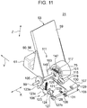
- the nip release mechanism 106 includes a second cam member 105, a first shift lever 123, and a second shift lever 127.
- the second cam member 105 is made integral with the rotation shaft 99 of the transport roller 75.
- the first shift lever 123 has one end 123a that abuts the second cam member 105, another end 123b provided with a shaft 124, and an intermediate portion 123c to which a spring 125 that pulls the intermediate portion 123c upward is attached.
- the second shift lever 127 has one end 127a ( Fig.
- the second cam member 105 pushes the one end 123a of the first shift lever 123 downward by a specified amount when the pushing of the advancing/retreating member 103 is performed. Furthermore, the one end 127a of the second shift lever 127 is pushed downward by a specified amount due to tilting of the first shift lever 123 about the tilting shaft 124.
- the pivot shaft 129 attached to the other end 127b of the second shift lever 127 pivots by a specified angle.
- the nipping roller 109 provided at the pivot free end of the nipping member 107 is separated from the transport roller 75, thereby the nip is released.
- the stacker 21 includes a nipping member 107 that, together with the transport roller 75, nips the medium P therebetween and transmits a transport force of the transport roller 75 to the medium P while nipping the medium P.
- a nipping member 107 that, together with the transport roller 75, nips the medium P therebetween and transmits a transport force of the transport roller 75 to the medium P while nipping the medium P.
- the nipping member 107 can be displaced between a position where the nipping member 107 together with the transport roller 75 forms a nip therebetween and a position where the nip between the nipping member 107 and the transport roller 75 is released.
- the second cam member 105 provided on the rotation shaft 99 of the transport roller 75 is moved in accordance with the rotation of the rotation shaft 99 of the transport roller 75, thereby displacing the nipping member 107 between the nipping state and the nip release state.
- the nipping member 107 is set in the nip release state while the advancing/retreating member 103 is pushing the surface of the support plate 59 of the support member 53 with the medium P pinched therebetween.
- the transport force of the transport roller 75 is reduced, thereby reducing jamming, creasing, and the like of the medium P.
- a certain gap (for example, 1 to 10 mm) is formed between the transport roller 75 and the medium P supported by the support member 53, so that the succeeding medium P being ejected is stacked along the front side of the medium P having been stacked and supported so as to be inclined as has been described.
- This operation is realized by the above-described receding mechanism 111 and the position maintaining mechanism 56.
- an operating form of the processing apparatus 1 according to the present embodiment is described by focusing on the operation of the stacker 21 according to the present embodiment with an example case where a plurality of the media P such as postcards or envelopes on which processes of recording addresses, text, or the like have been performed are stacked by using the stacker 21.
- the operating form of the processing apparatus 1 is divided into four steps as follows: (A) mounting of the stacker; (B) preparation for stacking; (C) start of the stacking; and (D) end of the stacking and removal of the media.
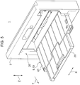
- the handle (not illustrated) provided in the front surface of the medium ejection tray 8 closing the ejection opening 20 formed in the side surface of the apparatus main body 2 is held by a hand so as to open the medium ejection tray 8 as illustrated in Fig. 5 .
- the rear surface of the medium ejection tray 8 becomes the obverse side and the placement surface 23 is exposed.
- the stacker 21 is placed on the placement surface 23 and positioned by, for example, fitting projections (not illustrated) or the like formed on a lower surface of the base frame 37 of the stacker 21 into recesses (not illustrated) or the like formed in the placement surface 23.
- the upstream side of the stacker 21 in the ejecting direction Y is inserted into the ejection opening 20 while being slightly inclined downward so as to perform the positioning with the projections or the like and the recesses or the like.
- the downstream end side of the stacker 21 in the ejecting direction Y is moved downward so as to mount the stacker 21 on the placement surface 23 as illustrated in Fig. 4 .
- movements of the stacker 21 in the XY plane parallel to the placement surface 23 of the medium ejection tray 8 are regulated by the engagement of the projections or the like with the recesses or the like, and movements of the stacker 21 are also regulated in the vertical direction Z by abutment of an upper surface of the top plate portion of the support frame 137 having an inverted U shape provided in the space on the upstream side of the base frame 37 in the ejecting direction Y against a lower surface or the like of a top plate portion of the ejection opening 20.
- the transmission rollers 79L and 79R which are provided at the upstream end of the stacker 21 in the ejecting direction Y abut the ejection rollers 18L and 18R, which are provided in the ejection unit 10 of the processing apparatus 1.
- This allows the motive power to be transmitted to the transport roller 75 of the stacker 21 via the power transmission unit 77. Accordingly, high-speed stacking of the media P in the edge placement orientation (standing orientation) can be performed.
- the handle portions 47 are held so as to adjust the distance between the left and right side guide portions 41L and 41R in accordance with the width of the media P to be stacked, and the fixing screws 45 are tightened so as fix the positions where the side guide portions 41L and 41R are attached.
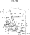
- the support member 53 is fixed at the maximum stack position at the downstream end in the ejecting direction Y as illustrated in Fig. 18A , the retaining claw 71 projecting from a lower end of the slide block 61 of the support member 53 is pulled out from the retaining hole 73 formed near the downstream end in the upper surface of the base frame 37 in the ejecting direction Y.
- the fixed state of the support member 53 is released.
- the regulation release lever 60 provided in the support member 53 is pushed toward the upstream side in the ejecting direction Y so as to separate the regulating portion 58 from the wound portion of the constant force spring 57. This releases the regulation of the movement of the support member 53 by the regulating portion 58 toward the upstream side in the ejecting direction Y.
- the force of the constant force spring 57 for restoration of the original shape acts on the support member 53.
- the support member 53 can be moved to the stack start position at the upstream end in the ejecting direction Y while being guided by the projection 65 and the guide hole 63 ( Fig. 16 ).
- a force to return to the downstream side in the ejecting direction Y is caused to act on the regulation release lever 60 (operating portion 149).
- the regulating portion 58 abuts the wound portion of the constant force spring 57 again.
- the movement of the support member 53 toward the upstream side in the ejecting direction Y is regulated.
- the regulating portion 58 regulates the movement of the support member 53 toward the upstream side and does not regulate the movement of the support member 53 toward the downstream side in the ejecting direction Y.
- the ejection of the medium P is performed by rotating the ejection rollers 18.
- the rotation of the ejection rollers 18 is transmitted to the transport roller 75 via the power transmission unit 77, thereby the transport roller 75 is rotated in a direction in which the medium P is fed to the stacking region 27 of the stacker 21.
- the medium P ejected by the ejection rollers 18 is guided by the entrance guides 136 and moved to the stacker 21 side with side end portions thereof positioned in the gaps between the horizontal portions 135 of the left and right lifting-off suppressing members 133L and 133R and the upper surface of the base frame 37.
- the medium P is transported in the face placement orientation (lying orientation) along the upper surface of the base frame 37 until a leading end thereof reaches a nipping point O ( Figs. 15 and 16 ) between the transport roller 75 and the nipping member 107.
- the leading end of the medium P When the leading end of the medium P reaches the nipping point O, the medium P is nipped between the transport roller 75 and the nipping roller 109. Thus, the feeding force of the transport roller 75 is transmitted to the leading end of the medium P. Then, the leading end of the medium P is caused to abut the surface of the support plate 59 of the support member 53 on the downstream side.
- the leading end of the medium P abutting the surface of the support plate 59 is guided by the inclined surface of the support plate 59 without being changed and moved diagonally upward along the surface.
- the side end portions of the medium P in the width direction X are positioned in the gaps between the rear surfaces of the inclined portions 134 of the lifting-off suppressing members 133 and the front surface of the support plate 59.
- lifting-off of the left and right side end portions of the medium P is suppressed by the inclined portions 134 (third lifting-off suppressor). Accordingly, transition of the orientation and transportation of the medium P are smoothly performed.
- the movement of the support member 53 toward the upstream side in the ejecting direction Y is regulated by the regulating portion 58 of the position maintaining mechanism 56.
- the support member 53 is stopped at a position where the support member 53 has receded by the specified distance S without being changed and ready for stacking of the next medium P.
- the nip release mechanism 106 also performs a specified operation in synchronization with the operation of the receding mechanism 111. That is, due to the rotation of the rotation shaft 99 of the transport roller 75, the second cam member 105 is rotated so as to push downward the one end 123a of the first shift lever 123. Thus, the first shift lever 123 is tilted downward against a force of the spring 125 directed upward.
- the downward tilting of the first shift lever 123 pushes downward the one end 127a of the second shift lever 127 and causes the pivot shaft 129 attached to the other end 127b to pivot in a direction in which the pivot free end of the nipping member 107 is pushed downward.
- This operation moves the nipping roller 109 from a nip position where the nipping roller 109 contacts a circumferential surface of the transport roller 75 to a nip release position where the nipping roller 109 is kept separated from the circumferential surface of the transport roller 75.
- transmission of the feeding force to the medium P is stopped.
- the feeding force transmitted from the transport roller 75 is reduced by releasing the nipping state between the transport roller 75 and the nipping member 107 when the receding mechanism 111 causes the advancing/retreating member 103 to perform the pushing. This suppresses the occurrence of creasing or the like in the medium P.
- the advancing/retreating member 103 is disposed at a retreated position where the advancing/retreating member 103 has been retreated to the upstream side in the ejecting direction Y, and the nipping member 107 is in the nipping state in which the nipping roller 109 abuts the circumferential surface of the transport roller 75 with the medium P nipped therebetween.
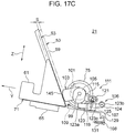
- the rotation shaft 99 of the transport roller 75 continues rotating and the stacker 21 enters a state illustrated in Figs. 12C and 17C , the advancing/retreating member 103 is moved to a pushing position on the downstream side in the ejecting direction Y.
- the support member 53 is pushed (via the stacked media P) in so as to recede by the specified distance S.
- the nipping member 107 pivots further so as to enter the nip release state in which the nipping roller 109 is kept separated from the circumferential surface of the transport roller 75.
- the advancing/retreating member 103 is gradually being retreated toward the above-described "retreated position".
- the nipping member 107 starts pivoting upward about the pivot shaft 129.
- the nipping force of the transport roller 75 and the nipping member 107 acting on the medium P is gradually increased, and accordingly, the feeding force acting on the medium P is increased.
- the state of the stacker 21 returns to the state illustrated in Figs. 12A and 17A .
- the media P are sequentially stacked one after another in the stacking region 27 of the stacker 21, and the support member 53 recedes on a specified-distance-S by specified-distance-S basis.
- a single medium P that is the last one of the media P is ejected to the outside of the apparatus main body 2 by the ejection rollers 18 through the ejection opening 20.
- the medium P ejected by the ejection rollers 18 is transported toward the stacking region 27 through the transport operation performed by the transport roller 75 and the nipping member 107. Thus, stacking of all the media P is completed.
- the support member 53 can be moved to the maximum stack position at the downstream end in the ejecting direction Y, and the retaining claw 71 projecting from the lower end of the slide block 61 of the support member 53 is retained in the retaining hole 73 formed in the base frame 37.
- the support member 53 is fixed at the maximum stack position. This increases ease of removal of the media P stacked in the stacking region 27, and combined with the fact that the height of the guide side plates 55L and 55R of the side guide portions 41L and 41R is reduced on the downstream side in the ejecting direction Y, the media P can be smoothly removed.
- the media P stacked in the stacker 21 assume an edge placement orientation (standing orientation) in which the media P are inclined with the upper portion thereof being further in the ejecting direction Y than the lower portion thereof. Accordingly, compared to the related-art processing apparatus that does not use the stacker 21 and stacks the media P in the face placement orientation (lying orientation) on the placement surface 23 of the medium ejection tray 8, the number of the media P to be stacked can be significantly increased.
- the position of the support member 53 can gradually recede in accordance with the progress of stacking of the media P instead of being constantly fixed at the maximum stack position.
- the need of a conveyer belt or the like that transports the media P to the maximum stack position is dropped, and accordingly, the techniques herein can contribute to reduction in size, weight, and cost of the apparatus.
- the stacker 21 that has a large stacking capacity so as to be usable with a high-speed processing apparatus performing specified processes at high speed and that is capable of continuous stacking, and it is also possible to provide the processing apparatus 1 that includes the stacker 21.
- stacker 21 and the processing apparatus 1 basically have the structures having been described, of course, it is possible to change or omit partial structures without departing from the scope of the invention.
- processing apparatus 1 according to the invention is not limited to an ink jet printer.
- the processing apparatus 1 according to the invention can be used for another recording apparatus, copier, or the like such as a laser printer.
- the processing apparatus 1 according to the invention can be used for any of a variety of other processing apparatuses that perform certain processes on a large amount of the media P at high speed.
- the power transmission unit 77 does not necessarily have a structure in which the motive power is obtained through pressure contact of the transmission rollers 79 with the ejection rollers 18.
- the motive power may be obtained from gears, pulleys, or the like for outputting provided on the shaft 25 of the ejection rollers 18.
- the media P to be stacked in the stacker 21 are not limited to postcards or envelopes in a portrait format.
- the media P to be stacked may be postcards or envelopes in a landscape format.
- the media P may be media P of another type such as business cards or another media having no definite form.
- rotation of a motor that is independently provided in the stacker 21 can be utilized to operate the transport roller 75, the receding mechanism 111, and the nip release mechanism 106.
Abstract
Description
- The present invention relates to a stacker and a processing apparatus. The stacker is disposed at an ejection opening of the processing apparatus and causes media to be ejected through the ejection opening to be stacked and placed.
- Examples of such a stacker include those of, for example,
JP-A-11-199113 JP-A-10-194553 - In the above-described related-art stackers, the support member is fixed at the position largely separated from the ejection opening of a processing apparatus such as a printer instead of being positioned close to the ejection opening of the processing apparatus. This allows a larger amount of media to be stacked. However, since the position of the support member is fixed, the conveyor is necessary for transportation of the media to the separated position of the support member. Thus, there arises a problem in that the entirety of the stacker is increased in size. Furthermore, transportation by the conveyor belt is added. This gives rise to a problem in that control of transport operation for stacking becomes complex.
- An advantage of some aspects of the invention is that an increase in size of a stacker can be suppressed while the amount of media to be stacked can be increased.
- In order to obtain the above-described advantage, a stacker according to a first aspect of the invention is disposed at an ejection opening of a processing apparatus and causes media ejected through the ejection opening to be stacked and placed on a stacking surface. The stacker includes a support member, a receding mechanism, and a position maintaining mechanism. The support member is movable toward an upstream side and a downstream side in an ejecting direction, receives each of the media ejected through the ejection opening, and supports the medium in such an orientation that the medium is inclined with an end edge of the medium on the downstream side in the ejecting direction positioned above an end edge of the medium on the upstream side in the ejecting direction and that the end edge of the medium on the upstream side in the ejecting direction abuts the stacking surface. The receding mechanism causes the support member to recede toward the downstream side. The position maintaining mechanism maintains a position of the support member having been moved by the receding mechanism.
- According to the first aspect, the support member that supports the media in an upwardly inclined orientation, that is, in a standing orientation is movable toward the upstream side and the downstream side in the ejection direction. Furthermore, the receding mechanism can cause the support member to recede toward the downstream side, and the position maintaining mechanism can maintain the position of the support member having receded by the specified distance, that is the position maintaining mechanism can hold the support member at this position. Thus, when the medium is supported by the support member so as to be in the standing orientation, the support member recedes by the specified distance and is kept at the position to which the support member has receded. This can ensure a space to support the next medium.
- Accordingly, when
- 1. the receding of the support member by the specified distance,
- 2. operation to support the medium in the standing orientation at the support space for the medium ensured by the receding, and
- 3. the next receding
- Here, the term "maintain the position of the support member" means that the support member is held at the position to which the support member has been moved by the receding mechanism. However, this does not necessarily mean that the support member does not move at all. The position of the support member may move at low speed as long as a technical significance of the above-described term "maintain the position" (a state in which operation for supporting the next medium in the standing orientation can be performed at the support space for the media obtained by the receding) is substantially satisfied.
- It is preferable that the position maintaining mechanism include a pulling mechanism that applies to the support member a pulling force to pull toward the upstream side and a suppressing mechanism that suppresses the pulling force at a position to which the support member has been caused to recede by a specified distance by the receding mechanism.
- Here, the term "suppresses the pulling force" means canceling of the pulling force so as to maintain the support member at the position or reduction of the pulling force.
- Thus, the position maintaining mechanism that maintains the position of the support member having been moved by the receding mechanism can be realized with a simple structure.
- It is preferable that, in order to recede the support member, the receding mechanism apply a moving force to move against a frictional force caused by frictional resistance with the stacking surface which serves as a surface sliding against the support member. In this case, the position maintaining mechanism maintains the position of the support member by utilizing the frictional resistance.
- Thus, the position of the support member having been moved by the receding mechanism is maintained at the position by utilizing the frictional force of the sliding surface. Accordingly, the position maintaining mechanism can be realized with a simple structure in which the constant force spring or the like is not used.
- It is preferable that stacker further include a transport roller that receives the medium ejected through the ejection opening and that transports the medium toward the downstream side. In this case, the transport roller is driven by transmitting motive power with which the processing apparatus ejects the medium.
- Thus, the stacker includes the transport roller that transports toward the downstream side the medium ejected through the ejection opening. By setting the transport roller as a base point of a medium transport path of the stacker, the design of the medium transport path and transport control can be simply performed.
- Furthermore, the transport roller is driven by utilizing the motive power of the processing apparatus for the ejection. Accordingly, no dedicated motive power source is required.
- It is preferable that the transport roller be driven by transmitting the motive power from a rotation shaft of an ejection roller positioned at a most downstream portion of the processing apparatus in the ejecting direction.
- Thus, the motive power is transmitted to the transport roller from the rotation shaft of the ejection roller positioned at the most downstream portion near the ejection opening on the processing apparatus side. This allows the motive power transmission structure to be realized with a simple structure.
- It is preferable that the receding mechanism include an advancing/retreating member provided on a rotation shaft of the transport roller. In this case, the advancing/retreating member repeatedly performs, linked with the rotation of the rotation shaft of the transport roller, pushing of the support member and retreating from the support member.
- Thus, the advancing/retreating member provided on the rotation shaft of the transport roller repeatedly performs, linked with the rotation of the rotation shaft of the transport roller, pushing of the support member and retreating from the support member. This allows the receding mechanism to be realized with a simple structure. Furthermore, the receding of the support member by the specified distance can be performed by the "pushing" with the advancing/retreating member, and the operation to ensure the support space for the medium through the receding of the support member can be performed by the "retreating".
- It is preferable that the receding mechanism include a first cam member provided on the rotation shaft of the transport roller. In this case, the first cam member causes, linked with the rotation of the rotation shaft of the transport roller, the advancing/retreating member to perform the pushing and the retreating.
- Thus, the pushing and the retreating by the advancing/retreating member can be realized with a simple structure by using the first cam member provided on the rotation shaft of the transport roller.
- It is preferable that the stacker further include a nipping member that, together with the transport roller, nips the medium therebetween so as to transmit a transport force of the transport roller to the medium while the medium is being nipped. In this case, the nipping is released when the advancing/retreating member performs the pushing.
- Thus, the nipping performed by the nipping member paired with the transport roller so as to transmit the transport force to the medium is released while the advancing/retreating member is performing the pushing. Thus, the transport force is not transmitted to the medium while the pushing is being performed. Accordingly, during the operation to ensure the support space for the medium through the receding, the medium is not fed into the support space by the "pushing" of the advancing/retreating member. This can reduce the likelihood of jamming or creasing of the medium.
- It is preferable that the nipping member be able to be displaced between a position at which the nipping member together with the transport roller performs the nipping and a position at which the nipping is released, and a second cam member be provided on the rotation shaft of the transport roller. In this case, the second cam member causes, linked with the rotation of the rotation shaft of the transport roller, the nipping member to be displaced.
- Thus, the second cam member provided on the rotation shaft of the transport roller causes the nipping member to be displaced between the position at which the nipping member performs the nipping and the position at which the nipping is released. Accordingly, the nipping can be released with a simple structure.
- It is preferable that the pulling mechanism be a constant force spring, and the suppressing mechanism be a regulating portion that regulates rotation of the constant force spring in a direction in which the constant force spring is wound.
- Thus, the position maintaining mechanism can be easily realized with the constant force spring.
- It is preferable that the stacker be a unitized device that is removably mountable in the processing apparatus.
- Thus, the stacker is the unitized device that is removably mountable in the processing apparatus. Accordingly, stacking with the stacker and stacking performed by the processing apparatus itself without the stacker can be switched.
- In particular, when the transport roller is driven by transmitting the motive power from a rotation shaft of the ejection roller positioned at the most downstream portion of the processing apparatus in the ejecting direction as has been described, the motive power on the processing apparatus side can be easily utilized with the structure in which the unitized stacker can be set in alignment with the ejection opening of the processing apparatus.
- A processing apparatus according to a second aspect of the invention includes a processing unit, an ejection mechanism, and a stacker unit. The processing unit performs a specified process on media. The ejection mechanism ejects through an ejection opening the media transported thereto through the processing unit. The stacker unit receives the media ejected through the ejection opening and stacks the media. In this case, the stacker unit is any one form of the above-described stacker.
- Thus, the processing apparatus can obtain the effects produced by any one form of the stacker.
- Embodiments of the invention will now be described by way of example only with reference to the accompanying drawings, wherein like numbers reference like elements.
-
Fig. 1 is a perspective view of an example of a processing apparatus according to an embodiment of the invention seen from a diagonally front right side. -
Fig. 2 is a perspective view of the example of the processing apparatus according to the embodiment seen from a diagonally front left side. -
Fig. 3 is a front view of the example of the processing apparatus according to the embodiment. -
Fig. 4 is a perspective view illustrating a state in which a stacker is disposed in an ejection unit of the processing apparatus according to the embodiment. -
Fig. 5 is a perspective view illustrating a use state of the ejection unit of the processing apparatus according to the embodiment. -
Fig. 6 is a perspective view of the stacker according to the embodiment seen from a diagonally rear left side. -
Fig. 7 is a perspective view of the stacker according to the embodiment seen from a diagonally front left side. -
Fig. 8 is a perspective view of the stacker according to the embodiment seen from a diagonally front right side. -
Fig. 9 is a perspective view of a power transmission unit of the stacker according to the embodiment. -
Fig. 10 is a perspective view of a receding mechanism and a position maintaining mechanism of the stacker according to the embodiment seen from a diagonally front right side. -
Fig. 11 is a perspective view of the receding mechanism and the position maintaining mechanism of the stacker according to the embodiment seen from a diagonally front left side. -
Fig. 12A is a perspective view of the receding mechanism illustrating operation of the stacker according to the embodiment, specifically illustrating a state in which an advancing/retreating member has been retreated. -
Fig. 12B is a perspective view of the receding mechanism illustrating the operation of the stacker according to the embodiment, specifically illustrating a state in which the advancing/retreating member is being pushed. -
Fig. 12C is a perspective view of the receding mechanism illustrating the operation of the stacker according to the embodiment, specifically illustrating a state in which the advancing/retreating member has been pushed. -
Fig. 12D is a perspective view of the receding mechanism illustrating the operation of the stacker according to the embodiment, specifically illustrating a state in which the advancing/retreating member is retreating. -
Fig. 13 is a perspective view of the support member and the position maintaining mechanism of the stacker according to the embodiment seen from a diagonally upper left side. -
Fig. 14 is a perspective view of the support member and the position maintaining mechanism of the stacker according to the embodiment seen from a diagonally lower left side. -
Fig. 15 is a side sectional view of the stacker according to the embodiment with the support member positioned at a maximum stack position. -
Fig. 16 is a side sectional view of the stacker according to the embodiment with the support member positioned at a stack start position. -
Fig. 17A is a side view of the receding mechanism illustrating the operation of the stacker according to the embodiment, specifically illustrating a state in which the advancing/retreating member has been retreated. -
Fig. 17B is a side view of the receding mechanism illustrating the operation of the stacker according to the embodiment, specifically illustrating a state in which the advancing/retreating member is being pushed. -
Fig. 17C is a side view of the receding mechanism illustrating the operation of the stacker according to the embodiment, specifically illustrating a state in which the advancing/retreating member has been pushed. -
Fig. 17D is a side view of the receding mechanism illustrating the operation of the stacker according to the embodiment, specifically illustrating a state in which the advancing/retreating member is retreating. -
Fig. 18A is a side sectional view illustrating the operation of the stacker according to the embodiment with a regulating portion set in a regulating state. -
Fig. 18B is a side sectional view illustrating the operation of the stacker according to the embodiment with the regulating portion set in a regulation release state. - With a multi-functional ink jet printer that includes stacking-type medium cassettes, a medium feed tray for manual feeding, and a medium ejection tray for manual ejection as an example of a processing apparatus according to an embodiment of the invention, the structure of the processing apparatus according to the embodiment of the invention, the structure of a stacker according to the embodiment of the invention used for the medium ejection tray of the processing apparatus, and forms of operation of the processing apparatus mainly including operation of the stacker will be described in detail below with reference to the accompanying drawings.
- In the following description, first, an outline of the overall structure of the processing apparatus according to the embodiment of the invention is described based on
Figs. 1 to 3 . Next, the structure of an ejection unit is briefly described. The ejection unit includes the medium ejection tray for which the stacker according to the embodiment of the invention is used and members around the medium ejection tray. Next, the structure of the stacker according to the embodiment of the invention used for the medium ejection tray is specifically described. After that, the forms of operation of the processing apparatus according to the embodiment of the invention mainly including operation of the stacker are described. Finally, reference is made to the structures of other embodiments that are partially different from the structure of the embodiment are referred to. - A
processing apparatus 1 illustrated in the drawings is a multi-functional ink jet printer that includes ascanner unit 3,medium cassettes 5A to 5D, amedium feed tray 7, and amedium ejection tray 8. Thescanner unit 3 is disposed in an upper portion of an apparatusmain body 2. For example, fourmedium cassettes 5A to 5D are disposed in a lower portion of the apparatusmain body 2. Themedium cassettes 5A to 5D are stacked one on top of another. Themedium feed tray 7 is disposed in, for example, a right side surface of the apparatusmain body 2. Themedium feed tray 7 is used for manual feeding. Themedium ejection tray 8 is disposed in, for example, a left side surface of the apparatusmain body 2. Themedium ejection tray 8 is used for manual ejection. - Furthermore, a display/
operating panel 9 is provided, for example, on the left-hand side of an upper portion of the apparatusmain body 2 as viewed from the front. The display/operating panel 9 is for setting various items and performing operations of theprocessing apparatus 1. A comparatively large space A is formed, for example, on the righthand side of the display/operating panel 9 as viewed from the front. Media P which have been fed from themedium cassettes 5A to 5D and on which processes have been performed are received in the space A in a face placement orientation. The bottom of the space A is anejection stacker 11. - Furthermore, a standard-
equipment medium cassette 5A is provided uppermost in the stackedmedium cassettes 5A to 5D in a lower portion of the apparatusmain body 2. Three additionalmedium cassettes 5B to 5D are provided below themedium cassette 5A. Furthermore, themedium feed tray 7 of, for example, an opening/closing lid type for manual feeding is provided in, for example, the right side surface of the apparatusmain body 2 as viewed from the front. Furthermore, themedium ejection tray 8 of, for example, an opening/closing lid type for manual ejection is provided in, for example, the left side surface of the apparatusmain body 2 as viewed from the front. - Furthermore, the apparatus
main body 2 includes therein aprocessing unit 13, atransport unit 17, anejection unit 10, and acontroller 19. Theprocessing unit 13 performs specified printing processes by ejecting droplets of colors (for example, four colors including cyan (C), magenta (M), yellow (Y), and black (K)) to each of the media P having been fed from one of themedium cassettes 5A to 5D or themedium feed tray 7. Thetransport unit 17 transports the media P toward aprocessing region 15 of theprocessing unit 13. Theejection unit 10 ejects to the outside of the apparatusmain body 2 the media P which have been fed from themedium feed tray 7 and on which processes have been performed. Thecontroller 19 controls various operations of theprocessing unit 13, thetransport unit 17, and theejection unit 10, items displayed in the display/operating panel 9, and so forth by receiving information from the display/operating panel 9 and external devices such as a personal computer (PC) and the like. - As the
processing unit 13, a so-called line-head-type processing head is provided. The line-head-type processing head performs a process (for example, recording) in a width direction X of each of the media P entirely at a time. This process is performed at a fixed feed pitch. The width direction X intersects a direction Y in which the media P are transported. - Of course, in the case where the quality of processing is considered as more important than the processing speed for the
processing apparatus 1, a so-called serial-head-type processing head can be used. The serial-head-type processing head is mounted on a carriage (not illustrated) and is reciprocated in the width direction X so as to perform a specified process. - A transport unit into which, for example, the following components are unitized is used as the transport unit 17: nipping transport rollers that transport toward the
processing region 15 or theejection unit 10, which will be described later, the media P having been fed by feeding rollers (not illustrated); motors that drive these components; gear trains, belts, and so forth; guide rollers and guide plates that guide transportation of the media P; and a reverse mechanism that reverses the transport direction. - The
processing apparatus 1 according to the present embodiment is basically structured with theprocessing unit 13, an ejection mechanism 18 (Fig. 9 ), and a stacker 21 (stacker unit) included therein. Theprocessing unit 13 performs specified processes on the media P. Theejection mechanism 18 ejects through anejection opening 20 the media transported thereto through theprocessing unit 13. Thestacker 21, which will be described later, receives media P ejected through theejection opening 20 and stacks the received media P one on top of another. - Furthermore, according to the present embodiment, the unitized
stacker 21 removably disposed in theejection unit 10 of theprocessing apparatus 1 is used. - Herein, "face placement orientation", which may alternatively be referred to as "lying orientation", refers to an orientation in which the media P are stacked such that the faces of the media P are (preferably horizontally) placed along a
placement surface 23 of themedium ejection tray 8, and "edge placement orientation", which may alternatively be referred to as "standing orientation", refers to an orientation in which the media P are stacked such that the edges of a plurality of the media P are in contact with a stackingsurface 22 of thestacker 21, which will be described later, that is, the media P stand erect. - Accordingly, compared to a method of using only with the
medium ejection tray 8 on which media P are stacked in the face placement orientation (lying orientation), it is possible to significantly increase the number of the media P that can be stacked by using thestacker 21 that allows a large number of the media P to be stacked in the edge placement orientation (standing orientation). - For example, the
ejection unit 10 includes the ejection opening 20, themedium ejection tray 8, and ejection rollers 18 (Fig. 9 ). Theejection opening 20 is formed in, for example, the left side surface of the apparatusmain body 2. Themedium ejection tray 8 openably closes theejection opening 20. Theejection rollers 18 are provided on the apparatusmain body 2 side so as to face theejection opening 20 and serve as elements of the ejection mechanism. - The
ejection opening 20 has a rectangular window shape elongated in the width direction X. Theejection opening 20 has a recessed space extending slightly inward from the side surface of the apparatusmain body 2. Themedium ejection tray 8 has pivot supports (not illustrated) disposed at lower portions of inner surfaces at both end portions in the width direction X in the recessed space. Themedium ejection tray 8 is pivotable about the pivot supports between a position where themedium ejection tray 8 is in a closed state in which themedium ejection tray 8 closes the ejection opening 20 formed in the side surface of the apparatusmain body 2 while being parallel to this side surface and a position where themedium ejection tray 8 is in an open state in which themedium ejection tray 8 is opened so as to expose the ejection opening 20 while themedium ejection tray 8 intersects this side surface at an angle θ (Fig. 15 ). - According to the illustrated embodiment, the angle θ at which the
medium ejection tray 8 intersects the side surface is set to, for example, about 80°. Due to this setting, theplacement surface 23 of themedium ejection tray 8 extending toward the downstream side in a direction Y in which the media P is ejected becomes an upward inclination of about 10°. - A handle (not illustrated) is provided in a front surface of the
medium ejection tray 8. A user holds this handle to cause themedium ejection tray 8 to pivot. A rear surface of themedium ejection tray 8 is theplacement surface 23 on which the media P is placed in the face placement orientation (lying orientation). Anextension tray 29 is connected to themedium ejection tray 8 at a distal end portion of themedium ejection tray 8. Theextension tray 29 can be drawn out in the direction Y in which the media P is ejected and retracted in the opposite direction. Although it is not illustrated, theplacement surface 23 of themedium ejection tray 8 has, for example, a recess, and abase frame 37 of thestacker 21, which will be described later, has, for example, a projection at its bottom surface. With this structure, positioning in a planar direction XY parallel to theplacement surface 23 is performed by fitting the projection into the recess. - As illustrated in
Fig. 9 , a plurality of (six according to the illustrated embodiment) theejection rollers 18, which are, for example, formed of rubber, are disposed on ashaft 25 horizontally extending in the width direction X such that theejection rollers 18 are appropriately spaced from one another in the width direction X. Motive power is transmitted from, for example, thetransport unit 17 in the apparatusmain body 2 to theshaft 25 so as to rotate theshaft 25 in an ejection direction Y in which the medium P is ejected. - Furthermore, the
stacker 21, which will be described next, is not particularly provided with a motive power source. Thestacker 21 performs specified operations by receiving motive power from theejection rollers 18 rotated together with theshaft 25. - According to the present embodiment, the
stacker 21 is provided at the ejection opening 20 of theprocessing apparatus 1 and stacks the media P ejected through theejection opening 20. The media P are stacked in the direction Y in which the media P is ejected. The media P stacked are in the edge placement orientation (standing orientation). - The
stacker 21 basically includes asupport member 53, a recedingmechanism 111, and a position maintaining mechanism 56. Thesupport member 53 is movable toward the upstream side and the downstream side in the ejecting direction Y, receives the media P ejected through the ejection opening 20, and supports the media P such that the media P are inclined upward at an inclination angle α (Fig. 15 ). The receding mechanism 111 (Figs. 7 to 12D ) causes thesupport member 53 to recede toward the downstream side in the ejecting direction Y. The position maintaining mechanism 56 (Figs. 6 and9 to 14 ) that maintains the position of thesupport member 53 having been moved by the recedingmechanism 111. - As illustrated in
Figs. 13 to 16 and18A to 18D , the position maintaining mechanism 56 includes a pulling mechanism 57 and a suppressing mechanism 58. The pulling mechanism 57 causes a force F (Fig. 15 ) that pulls toward the upstream side in the ejecting direction Y to act on thesupport member 53. The suppressing mechanism 58 (Fig. 14 ) suppresses the pulling force F at a position to which thesupport member 53 has been caused to recede by the recedingmechanism 111 by a specified distance S (Figs. 12C ,15 , and17C ). - Here, the term "suppresses the pulling force F" means both the following operations: maintaining the
support member 53 at the position by causing a force the magnitude of which is the same as the pulling force F and which is oppositely directed to the pulling force F to act so as to cancel the pulling force F; and causing a force the magnitude of which is not the same as the pulling force F and which is oppositely directed to the pulling force F to act so as to reduce the pulling force F. - As illustrated in
Figs. 6 and7 , thestacker 21 includes thebase frame 37 having a substantially rectangular plate shape. Various components to be described below are provided on an upper surface of thebase frame 37. - First, a pair of
side guide portions base frame 37 in the width direction X. Theside guide portions side guide portions side guide portions elongated holes 43 formed as examples in thebase frame 37. Theside guide portions screws 45 as examples having knobs at the heads thereof. Two fixingscrews 45 are provided at each side in the width direction X, that is, a total of four fixingscrews 45 are provided. - The
side guide portions portions 47 to be held by hands for operation when adjusting the distance between theside guide portions base plates 49 in contact with the upper surface of thebase frame 37 so as to hold theside guide portions - Furthermore, in the ejecting direction Y, the length of the
side guide portions base frame 37. A member of a transportation system, which will be described later, the recedingmechanism 111 that cooperates with the transport system member, and elements of a nip release mechanism 106 (Figs. 11 and12A to 12D), which will be described later, are disposed in a space upstream of theside guide portions region 27 of thestacker 21. - Meanwhile, in a space downstream of the
side guide portions Fig. 6 ) and an accommodating space are formed. Theguide scale 51 serves as a guide when the distance between theside guide portions support member 53 having moved to a maximum stacking position. Thesupport member 53 will be described later. - In addition to the above-described
guide scale 51, guide scales 51 are also formed beside upstream end portions of theside guide portions base plates 49 are utilized for these guide scales 51. - Furthermore, the height of guide side plates 55 that connect the
handle portions 47 and thebase plates 49 of theside guide portions side guide portions processing apparatus 1 are placed on thestacker 21 than on the downstream side where media P are removed from thestacker 21. - This improves performance with which the media P are aligned in a region on the upstream side of the
side guide portions side guide portions - The
support member 53 includes asupport plate 59 and aslide block 61. Thesupport plate 59 supports the media P in such an orientation that the media P are inclined toward the downstream side with upper portions thereof further in the ejecting direction Y than lower portions thereof. Theslide block 61 supports thesupport plate 59 such that thesupport plate 59 is movable toward the upstream side and the downstream side in the ejecting direction Y. According to the present embodiment, thesupport plate 59 is inclined at, for example, an inclination angle α (Fig. 15 ) of about 60° relative to the stackingsurface 22 of thestacker 21. The stackingsurface 22 is part of the upper surface of thebase frame 37, the left and right sides of which are defined by theside guide portions support plate 59. - The
slide block 61 includes aprojection 65, a winding mechanism 67 (Figs. 6 ,13 , and14 ), a regulating portion 58, a regulation release lever 60 (Figs. 6 ,15 , and16 ), and so forth. The projection 65 (Fig. 15 ) is provided in a lower surface of theslide block 61 and engaged with a guide hole 63 (Fig. 7 ) extending in the ejecting direction Y at the center of thebase frame 37 in the width direction X. The winding mechanism 67 (Figs. 6 ,13 , and14 ) is provided in theslide block 61 and comprises a constant force spring 57 (denoted by the same reference sign as that of the pulling mechanism) included in the pulling mechanism 57. The regulating portion 58 (Fig. 14 ) is included in the suppressing mechanism. The regulation release lever 60 (Figs. 6 ,15 , and16 ) is operated in order to release a stated regulation by the regulating portion 58. - Next, the transport system member is described. As has been described, the
stacker 21 according to the present embodiment moves the media P to the stackingregion 27 by driving the transport system member, which is described below, by using the rotation of theejection rollers 18 of theprocessing apparatus 1 as a motive power source. - As the transport system member, a transport roller 75 (for example,
Fig. 7 ) is provided. Thetransport roller 75 applies a feeding force to the media P ejected by theejection rollers 18 to the outside of the apparatusmain body 2. Thetransport roller 75 is attached to arotation shaft 99 supported by asupport frame 137 provided in a space on the upstream side of thebase frame 37 in the ejecting direction Y. Thetransport roller 75 is located, for example, at the center in thestacker 21 in the width direction X. - The
transport roller 75 paired with a nipping member 107 (for example,Fig. 8 ) provided below thetransport roller 75 nips the supplied media P, thereby applying the feeding force to the media P. As illustrated inFigs. 10 and11 , the nippingmember 107 includes a plate-shaped member that substantially horizontally extends toward the downstream side in the ejecting direction Y from a bent portion where the nippingmember 107 is bent downward. The bent portion is disposed at an end portion on the upstream side in the ejecting direction Y where apivot shaft 129 is integrally fixed with a fixingscrew 130. - For example, a nipping roller 109 (
Figs. 15 to 17D ) is provided at an end portion of the nippingmember 107 on the downstream side in the ejecting direction Y. This end portion is a pivot free end of the nippingmember 107. The nippingroller 109 is brought into contact with thetransport roller 75 for nipping operation. - Furthermore, retaining
claws 108 are provided at a lower end of the downwardly bent portion on the upstream side of the nippingmember 107. The retainingclaws 108 outwardly project to the left and right in the width direction X. A spring 131 (Figs. 10 to 12D ) is attached to each of the retainingclaws 108. Thespring 131 performs pushing so that the pivot free end of the nippingmember 107 is constantly displaced toward thetransport roller 75. - The nipping
roller 109 is a preferable structure for smooth transportation of the media P. However, the nippingroller 109 may be omitted when a sufficient feeding force can be obtained only by a contact of thetransport roller 75 with the pivot free end of the nippingmember 107. A Power Transmission Unit - Next, based on
Figs. 6 to 9 , the structure of apower transmission unit 77 is described. Thepower transmission unit 77 transmits the motive power of theejection rollers 18 to thetransport roller 75. Out of the, for example, six of theejection rollers 18 provided on theshaft 25, thepower transmission unit 77 utilizes, for example,ejection rollers second ejection roller 18 from the left end and asecond ejection roller 18 from the right end in the width direction X, respectively, to transmit the motive power (Fig. 9 ). - Specifically, the
power transmission unit 77 includes, for example,transmission rollers intermediate gears 85, asecond transmission gear 89, aninput pulley 93, and anoutput pulley 97. Thetransmission rollers ejection rollers transmission rollers shaft 81, on which thetransmission rollers transmission rollers shaft 87. Thesecond transmission gear 89 is engaged with one of the intermediate gears 85. Theinput pulley 93 is provided on ashaft 91, on which thesecond transmission gear 89 is provided, and rotated together with thesecond transmission gear 89. The rotation of theinput pulley 93 is transmitted via atoothed timing belt 95 to theoutput pulley 97 provided on therotation shaft 99, on which thetransport roller 75 is provided. Thus, theoutput pulley 97 is rotated together with thetransport roller 75. - Furthermore, according to the present embodiment, the
transport roller 75 is rotated in the opposite direction to the rotation direction of theejection rollers 18 and rotated at the same speed as the rotation speed of theejection rollers 18. Thus, the media P are smoothly moved and transported to thestacker 21. - Next, based on
Figs. 6 to 9 , lifting-off suppressingmembers members stacker 21. - That is, end edges of the
guide side plates side guide portions support plate 59 of thesupport member 53 is inclined. The lifting-off suppressingmembers members - The lifting-off suppressing
members inclined portions 134 andhorizontal portions 135. Theinclined portions 134 are provided along the end edges of theguide side plates side guide portions horizontal portions 135 extend from the lower ends of theinclined portions 134 toward the upstream side in the ejecting direction Y so as to be continuous with theinclined portions 134 and parallel to the upper surface of thebase frame 37. Furthermore, end portions of thehorizontal portions 135 on the upstream side in the ejecting direction Y slightly outwardly project to the left and right in the width direction X so as to have a large width. Thus, entrance guides 136 having, for example, a U-shaped section are provided of portions functioning as slopes that guide the media P ejected to the end portions by theejection rollers 18 so that misalignment in the width direction X is corrected and the media P comes to the center in the width direction X. - Furthermore, gaps having specified sizes are formed between each of the side edges of the medium P in the width direction X moved to the
stacker 21 and transported and a rear surface of a corresponding one of theinclined portions 134 and between these edge of the medium P and a lower surface of a corresponding one of thehorizontal portions 135. Lifting-off and inclination of the medium P are regulated within the sizes of these gaps. Accordingly, even when a force acts to displace an upper portion of the medium P having been transitioned to the edge placement orientation (standing orientation) toward the upstream side in the ejecting direction Y, the medium P is brought into contact with the rear surface of theinclined portion 134, and the medium P that is lifted off or inclined larger than the sizes of the above-described gaps is restored to the original position. Thus, smooth transportation of the media P on the stackingsurface 22 is maintained. - Furthermore, the
support frame 137 has asub-frame 141 at a top plate portion thereof. Thesub-frame 141 extends downward and has a substantially L shape in section (Figs. 8 and9 ). Thesub-frame 141 has aside wall portion 143 perpendicular to the upper surface of thebase frame 37 and a bottom plate portion parallel to the upper surface of thebase frame 37. The bottom plate portion serves as a suppressingplate 139 that suppresses lifting-off or bulging in the central portion of the medium P in the width direction X being moved to thestacker 21. - The position where the suppressing
plate 139 is provided is set upstream of thetransport roller 75 in the ejecting direction Y. An upstream end portion of the suppressingplate 139 is inclined slightly upward. This suppresses catching of the medium P by the suppressingplate 139 when the medium P is supplied with a large lifting-off formed therein. - Herein, in view of the above-described functions, the
horizontal portions 135 of the lifting-off suppressingmembers plate 139, and theinclined portions 134 are separately defined as first lifting-off suppressors, a second lifting-off suppressor, and a third lifting-off suppressor, respectively. - Next, based on
Figs. 10 to 12D and17A to 17D , the recedingmechanism 111 is described. The recedingmechanism 111 includes an advancing/retreatingmember 103 provided on therotation shaft 99 of thetransport roller 75. The advancing/retreatingmember 103 repeatedly performs, linked with the rotation of therotation shaft 99 of thetransport roller 75, pushing of thesupport member 53 and retreating from thesupport member 53. - Furthermore, the receding
mechanism 111 includes afirst cam member 101 made integral with therotation shaft 99 of thetransport roller 75. Thefirst cam member 101 causes the advancing/retreatingmember 103 to perform, linked with the rotation of therotation shaft 99 of thetransport roller 75, the pushing and the retreating. - The advancing/retreating
member 103 has a flat plate shape elongated in the ejecting direction Y as illustrated inFigs. 10 and11 . An end portion on the downstream side of the advancing/retreatingmember 103 in the ejecting direction Y has an arc shape (Figs. 17A to 17D ) having a large radius of curvature. This end portion serves as a pushingactuator 145 that abuts thesupport plate 59 of thesupport member 53 so as to cause thesupport member 53 to recede by a specified distance S (for example, 1 to 10 mm;Figs. 12C and17C to be referred to later). - Furthermore, the advancing/retreating
member 103 has a first fitting elongated hole 117 (Fig. 11 ) and a second fitting elongated hole 119 (Fig. 10 ). The first fitting elongatedhole 117 is fitted onto therotation shaft 99 of thetransport roller 75. The second fitting elongatedhole 119 is fitted onto aguide shaft 121 attached to the side wall portion 143 (Fig. 9 ) of thesub-frame 141. The advancing/retreatingmember 103 can repeatedly perform the above-described pushing and retreating within the length of these twoelongated holes - Furthermore, a
first shift pin 113 and asecond shift pin 115 spaced apart from each other by a specified distance in the ejecting direction Y are provided on a surface of the advancing/retreatingmember 103 on thetransport roller 75 side. Thefirst shift pin 113 and thesecond shift pin 115 project toward thetransport roller 75. Out of thefirst shift pin 113 and thesecond shift pin 115, thefirst shift pin 113 abuts thefirst cam member 101 so as to cause the advancing/retreatingmember 103 to move in the pushing direction with respect to thesupport member 53. In contrast, thesecond shift pin 115 abuts thefirst cam member 101 so as to cause the advancing/retreatingmember 103 to move in the retreating direction. - Furthermore, referring to
Fig. 11 , a spring denoted by areference sign 147 pulls thefirst shift pin 113 of the advancing/retreatingmember 103 toward thefirst cam member 101 so as to cause thefirst shift pin 113 to abut thefirst cam member 101. - Next, based on
Figs. 13 to 15 , the position maintaining mechanism 56 is described. As has been described, the position maintaining mechanism 56 includes the pulling mechanism 57 and the suppressing mechanism 58. According to the present embodiment, the pulling mechanism 57 includes, for example, the constant force spring 57 formed by winding an elongated plate spring to have a spiral shape. - An
unwound end 69 of the constant force spring 57 is fixed by a fixing screw (not illustrated) or the like to a portion of thebase frame 37 near a position where thetransport roller 75 is provided (Figs. 6 and15 ). Accordingly, a force to move thesupport member 53 toward the upstream side in the ejecting direction Y is generated by utilizing a force of the constant force spring 57 for restoration of the original shape. - Furthermore, the suppressing mechanism 58 according to the present embodiment includes the regulating portion 58 that includes, for example, a wedge-shaped member regulating the rotation of the constant force spring 57 in the winding direction. Instead of the wedge-shaped member, another member that similarly acts such as a one-way roller can be used as the regulating portion 58.
- Furthermore, as illustrated in
Fig. 13 , the regulation release lever 60 that switches the state of the regulating portion 58 between a regulating state and a regulation release state is provided in thesupport member 53. The regulation release lever 60 is connected to the regulating portion 58 at an end on the upstream side in the ejecting direction Y and provided with an operatingportion 149 at an end on the downstream side in the ejecting direction Y. - In order to move the
support member 53 positioned at the maximum stack position or at a midway in the stacking region 27 (Fig. 15 ) of thestacker 21 toward a stack start position at an upstream end in the ejecting direction Y, the operatingportion 149 of the regulation release lever 60 is pushed toward the upstream side in the ejecting direction Y so as to separate the regulating portion 58 from the wound portion of the constant force spring 57. Thus, regulation performed by the regulating portion 58 is released. - In contrast, in order to set the regulating portion 58 in the regulating state again, a force to return the operating
portion 149 toward the downstream side in the ejecting direction Y is applied by the spring 74 (Fig.15 ) so as to cause the regulating portion 58 to abut the wound portion of the constant force spring 57 again. Thus, the regulating portion 58 is set to the regulating state. - Other than this, a retaining
claw 71 projects downward on a lower surface of theslide block 61 that includes the windingmechanism 67 of the constant force spring 57. The retainingclaw 71 is retained in a slit-shaped retaining hole 73 (Figs. 6 and15 ) formed at a central portion near a downstream end of thebase frame 37 in the ejecting direction Y. Thus, thesupport member 53 can be kept at the maximum stack position where thesupport member 53 has receded rearward as much as possible. - Thus, in the
stacker 21, thesupport member 53 can be removably fixed to thebase frame 37 when thesupport member 53 has been receded to the maximum stack position. The Position Maintaining Mechanism: Frictional Resistance at a Sliding Surface - The receding
mechanism 111 may apply, when thesupport member 53 is receding, a moving force G to move thesupport member 53 against a frictional force R due to frictional resistance with the stackingsurface 22, which is a sliding surface, and the position maintaining mechanism 56 may maintain the position of thesupport member 53 by utilizing the frictional resistance. That is, thesupport member 53 may stand still at its position due to the frictional resistance when the moving force G against the frictional force R is not applied. - With the above-described structure, the position of the
support member 53 having been moved by the recedingmechanism 111 can be maintained at the position by utilizing the frictional force of the sliding surface. Accordingly, the position maintaining mechanism 56 can be realized with a simple structure in which the constant force spring or the like is not used. - Next, based on
Figs. 12A to 12D and17A to 17D , thenip release mechanism 106 is described. - For example, the
nip release mechanism 106 includes asecond cam member 105, afirst shift lever 123, and asecond shift lever 127. Thesecond cam member 105 is made integral with therotation shaft 99 of thetransport roller 75. Thefirst shift lever 123 has oneend 123a that abuts thesecond cam member 105, anotherend 123b provided with ashaft 124, and anintermediate portion 123c to which aspring 125 that pulls theintermediate portion 123c upward is attached. Thesecond shift lever 127 has one end 127a (Fig. 10 ) that abuts a lower surface of theintermediate portion 123c of thefirst shift lever 123 and anotherend 127b at which thesecond shift lever 127 is fixed to thepivot shaft 129 of the nippingmember 107 with a fixingscrew 128. - The
second cam member 105 pushes the oneend 123a of thefirst shift lever 123 downward by a specified amount when the pushing of the advancing/retreatingmember 103 is performed. Furthermore, the one end 127a of thesecond shift lever 127 is pushed downward by a specified amount due to tilting of thefirst shift lever 123 about the tiltingshaft 124. - Thus, the
pivot shaft 129 attached to theother end 127b of thesecond shift lever 127 pivots by a specified angle. This causes the nippingmember 107 attached to thepivot shaft 129 with the fixingscrew 130 to pivot in a direction separating from thetransport roller 75. Accordingly, the nippingroller 109 provided at the pivot free end of the nippingmember 107 is separated from thetransport roller 75, thereby the nip is released. - The relationships between the advancing/retreating
member 103, the nippingmember 107, and thenip release mechanism 106 having been described are summarized as follows. - The
stacker 21 according to the present embodiment includes a nippingmember 107 that, together with thetransport roller 75, nips the medium P therebetween and transmits a transport force of thetransport roller 75 to the medium P while nipping the medium P. When the advancing/retreatingmember 103 performs the pushing by which thesupport member 53 is caused to recede by the specified distance S (Figs. 12C and17C ), the nipping between thetransport roller 75 and the nippingroller 109 is released. - Furthermore, the nipping
member 107 can be displaced between a position where the nippingmember 107 together with thetransport roller 75 forms a nip therebetween and a position where the nip between the nippingmember 107 and thetransport roller 75 is released. Thesecond cam member 105 provided on therotation shaft 99 of thetransport roller 75 is moved in accordance with the rotation of therotation shaft 99 of thetransport roller 75, thereby displacing the nippingmember 107 between the nipping state and the nip release state. - With the
nip release mechanism 106 that has the above-described structure and performs the above-described operations, the nippingmember 107 is set in the nip release state while the advancing/retreatingmember 103 is pushing the surface of thesupport plate 59 of thesupport member 53 with the medium P pinched therebetween. Thus, the transport force of thetransport roller 75 is reduced, thereby reducing jamming, creasing, and the like of the medium P. - Furthermore, a certain gap (for example, 1 to 10 mm) is formed between the
transport roller 75 and the medium P supported by thesupport member 53, so that the succeeding medium P being ejected is stacked along the front side of the medium P having been stacked and supported so as to be inclined as has been described. This operation is realized by the above-described recedingmechanism 111 and the position maintaining mechanism 56. - Next, an operating form of the
processing apparatus 1 according to the present embodiment is described by focusing on the operation of thestacker 21 according to the present embodiment with an example case where a plurality of the media P such as postcards or envelopes on which processes of recording addresses, text, or the like have been performed are stacked by using thestacker 21. - In the following description, the operating form of the
processing apparatus 1 is divided into four steps as follows: (A) mounting of the stacker; (B) preparation for stacking; (C) start of the stacking; and (D) end of the stacking and removal of the media. - First, the handle (not illustrated) provided in the front surface of the
medium ejection tray 8 closing the ejection opening 20 formed in the side surface of the apparatusmain body 2 is held by a hand so as to open themedium ejection tray 8 as illustrated inFig. 5 . In this state, the rear surface of themedium ejection tray 8 becomes the obverse side and theplacement surface 23 is exposed. - Next, the
stacker 21 is placed on theplacement surface 23 and positioned by, for example, fitting projections (not illustrated) or the like formed on a lower surface of thebase frame 37 of thestacker 21 into recesses (not illustrated) or the like formed in theplacement surface 23. - In so doing, the upstream side of the
stacker 21 in the ejecting direction Y is inserted into the ejection opening 20 while being slightly inclined downward so as to perform the positioning with the projections or the like and the recesses or the like. After that, the downstream end side of thestacker 21 in the ejecting direction Y is moved downward so as to mount thestacker 21 on theplacement surface 23 as illustrated inFig. 4 . - In this state, movements of the
stacker 21 in the XY plane parallel to theplacement surface 23 of themedium ejection tray 8 are regulated by the engagement of the projections or the like with the recesses or the like, and movements of thestacker 21 are also regulated in the vertical direction Z by abutment of an upper surface of the top plate portion of thesupport frame 137 having an inverted U shape provided in the space on the upstream side of thebase frame 37 in the ejecting direction Y against a lower surface or the like of a top plate portion of theejection opening 20. - Furthermore, as illustrated in
Fig. 9 , when thestacker 21 is mounted on theplacement surface 23 of themedium ejection tray 8, thetransmission rollers stacker 21 in the ejecting direction Y abut theejection rollers ejection unit 10 of theprocessing apparatus 1. This allows the motive power to be transmitted to thetransport roller 75 of thestacker 21 via thepower transmission unit 77. Accordingly, high-speed stacking of the media P in the edge placement orientation (standing orientation) can be performed. - Next, the
handle portions 47 are held so as to adjust the distance between the left and rightside guide portions side guide portions support member 53 is fixed at the maximum stack position at the downstream end in the ejecting direction Y as illustrated inFig. 18A , the retainingclaw 71 projecting from a lower end of theslide block 61 of thesupport member 53 is pulled out from the retaininghole 73 formed near the downstream end in the upper surface of thebase frame 37 in the ejecting direction Y. Thus, the fixed state of thesupport member 53 is released. - Along with the releasing of the fixing, as illustrated in
Fig. 18B , the regulation release lever 60 provided in thesupport member 53 is pushed toward the upstream side in the ejecting direction Y so as to separate the regulating portion 58 from the wound portion of the constant force spring 57. This releases the regulation of the movement of thesupport member 53 by the regulating portion 58 toward the upstream side in the ejecting direction Y. - As a result of the above-described operation, the force of the constant force spring 57 for restoration of the original shape acts on the
support member 53. Thus, thesupport member 53 can be moved to the stack start position at the upstream end in the ejecting direction Y while being guided by theprojection 65 and the guide hole 63 (Fig. 16 ). Then, after thesupport member 53 has been moved to the stack start position, a force to return to the downstream side in the ejecting direction Y is caused to act on the regulation release lever 60 (operating portion 149). Thus, the regulating portion 58 abuts the wound portion of the constant force spring 57 again. In this way, the movement of thesupport member 53 toward the upstream side in the ejecting direction Y is regulated. Here, the regulating portion 58 regulates the movement of thesupport member 53 toward the upstream side and does not regulate the movement of thesupport member 53 toward the downstream side in the ejecting direction Y. - After the preparation for the stacking has been completed, specified processes of the
processing apparatus 1 are performed on the medium P fed from themedium feed tray 7. The medium P on which the processes have been performed is ejected to the outside of the apparatusmain body 2 from theejection unit 10. - The ejection of the medium P is performed by rotating the
ejection rollers 18. The rotation of theejection rollers 18 is transmitted to thetransport roller 75 via thepower transmission unit 77, thereby thetransport roller 75 is rotated in a direction in which the medium P is fed to the stackingregion 27 of thestacker 21. - The medium P ejected by the
ejection rollers 18 is guided by the entrance guides 136 and moved to thestacker 21 side with side end portions thereof positioned in the gaps between thehorizontal portions 135 of the left and right lifting-off suppressingmembers base frame 37. The medium P is transported in the face placement orientation (lying orientation) along the upper surface of thebase frame 37 until a leading end thereof reaches a nipping point O (Figs. 15 and16 ) between thetransport roller 75 and the nippingmember 107. - When curl or the like occurs in the medium P being transported, lifting-off at the left and right side end portions of the medium P is suppressed by the horizontal portions 135 (first lifting-off suppressors) of the lifting-off suppressing members 133. Lifting-off or bulging in the central portion of the medium P is suppressed by the suppressing plate 139 (second lifting-off suppressor;
Fig. 9 ) integral with thesub-frame 141. - When the leading end of the medium P reaches the nipping point O, the medium P is nipped between the
transport roller 75 and the nippingroller 109. Thus, the feeding force of thetransport roller 75 is transmitted to the leading end of the medium P. Then, the leading end of the medium P is caused to abut the surface of thesupport plate 59 of thesupport member 53 on the downstream side. - The leading end of the medium P abutting the surface of the
support plate 59 is guided by the inclined surface of thesupport plate 59 without being changed and moved diagonally upward along the surface. - Then, when a trailing end of the medium P has passed through the nipping point O, the medium P no longer receives the feeding force from the
transport roller 75. Thus, a trailing end edge of the medium P is caused to abut the stackingsurface 22 of thestacker 21, and the medium P assumes the edge placement orientation (standing orientation) in which the back side of the medium P is supported by thesupport member 53. Thus, stacking of a single medium P is completed. - At this time, the side end portions of the medium P in the width direction X are positioned in the gaps between the rear surfaces of the
inclined portions 134 of the lifting-off suppressing members 133 and the front surface of thesupport plate 59. Thus, lifting-off of the left and right side end portions of the medium P is suppressed by the inclined portions 134 (third lifting-off suppressor). Accordingly, transition of the orientation and transportation of the medium P are smoothly performed. - Furthermore, operations of the receding
mechanism 111 and thenip release mechanism 106 are started in accordance with the rotation of therotation shaft 99 of thetransport roller 75. Out of these, due to the rotation of therotation shaft 99 of thetransport roller 75, thefirst cam member 101 is rotated so as to move the advancing/retreatingmember 103 in the recedingmechanism 111 such that the advancing/retreatingmember 103 is pushed toward thesupport member 53 by the specified distance S. - This causes the
support member 53 to recede by the specified distance S, thereby ensuring a space for stacking the medium P to be ejected next between the surface of the medium P having been stacked and thetransport roller 75. - Furthermore, at this time, the movement of the
support member 53 toward the upstream side in the ejecting direction Y is regulated by the regulating portion 58 of the position maintaining mechanism 56. Thus, thesupport member 53 is stopped at a position where thesupport member 53 has receded by the specified distance S without being changed and ready for stacking of the next medium P. - Furthermore, the
nip release mechanism 106 also performs a specified operation in synchronization with the operation of the recedingmechanism 111. That is, due to the rotation of therotation shaft 99 of thetransport roller 75, thesecond cam member 105 is rotated so as to push downward the oneend 123a of thefirst shift lever 123. Thus, thefirst shift lever 123 is tilted downward against a force of thespring 125 directed upward. - The downward tilting of the
first shift lever 123 pushes downward the one end 127a of thesecond shift lever 127 and causes thepivot shaft 129 attached to theother end 127b to pivot in a direction in which the pivot free end of the nippingmember 107 is pushed downward. - This operation moves the nipping
roller 109 from a nip position where the nippingroller 109 contacts a circumferential surface of thetransport roller 75 to a nip release position where the nippingroller 109 is kept separated from the circumferential surface of thetransport roller 75. Thus, transmission of the feeding force to the medium P is stopped. - Thus, the feeding force transmitted from the
transport roller 75 is reduced by releasing the nipping state between thetransport roller 75 and the nippingmember 107 when the recedingmechanism 111 causes the advancing/retreatingmember 103 to perform the pushing. This suppresses the occurrence of creasing or the like in the medium P. - Next, based on
Figs. 12A to 12D and17A to 17D , the relationship between the position of the advancing/retreatingmember 103 and the nipping state or the nip release state between thetransport roller 75 and the nippingmember 107 is described. As illustrated inFigs. 12A and17A , immediately after the leading end of the medium P has reached the nipping point O, the medium P is subjected to a large feeding force from thetransport roller 75 and the nippingmember 107 in the nipping state, and transportation of the medium P starts. - At this time, the advancing/retreating
member 103 is disposed at a retreated position where the advancing/retreatingmember 103 has been retreated to the upstream side in the ejecting direction Y, and the nippingmember 107 is in the nipping state in which the nippingroller 109 abuts the circumferential surface of thetransport roller 75 with the medium P nipped therebetween. - When the
rotation shaft 99 of thetransport roller 75 continues rotating and thestacker 21 enters a state illustrated inFigs. 12B and17B , the advancing/retreatingmember 103 is gradually advancing in the pushing direction. Furthermore, the nippingmember 107 starts pivoting downward about thepivot shaft 129. Thus, a nipping force of thetransport roller 75 and the nippingmember 107 acting on the medium P is reduced, and accordingly, the feeding force acting on the medium P is reduced. - Furthermore, the
rotation shaft 99 of thetransport roller 75 continues rotating and thestacker 21 enters a state illustrated inFigs. 12C and17C , the advancing/retreatingmember 103 is moved to a pushing position on the downstream side in the ejecting direction Y. Thus, thesupport member 53 is pushed (via the stacked media P) in so as to recede by the specified distance S. At this time, the nippingmember 107 pivots further so as to enter the nip release state in which the nippingroller 109 is kept separated from the circumferential surface of thetransport roller 75. - Furthermore, when the
rotation shaft 99 of thetransport roller 75 continues rotating and thestacker 21 enters a state illustrated inFigs. 12D and17D , the advancing/retreatingmember 103 is gradually being retreated toward the above-described "retreated position". The nippingmember 107 starts pivoting upward about thepivot shaft 129. Thus, the nipping force of thetransport roller 75 and the nippingmember 107 acting on the medium P is gradually increased, and accordingly, the feeding force acting on the medium P is increased. - Then, when the
rotation shaft 99 of thetransport roller 75 continues rotating further, the state of thestacker 21 returns to the state illustrated inFigs. 12A and17A . After this, as the similar operations are being repeatedly performed, the media P are sequentially stacked one after another in the stackingregion 27 of thestacker 21, and thesupport member 53 recedes on a specified-distance-S by specified-distance-S basis. - When all the media P have been processed, a single medium P that is the last one of the media P is ejected to the outside of the apparatus
main body 2 by theejection rollers 18 through theejection opening 20. The medium P ejected by theejection rollers 18 is transported toward the stackingregion 27 through the transport operation performed by thetransport roller 75 and the nippingmember 107. Thus, stacking of all the media P is completed. - After the stacking of all the media P has been completed, the
support member 53 can be moved to the maximum stack position at the downstream end in the ejecting direction Y, and the retainingclaw 71 projecting from the lower end of theslide block 61 of thesupport member 53 is retained in the retaininghole 73 formed in thebase frame 37. Thus, thesupport member 53 is fixed at the maximum stack position. This increases ease of removal of the media P stacked in the stackingregion 27, and combined with the fact that the height of theguide side plates side guide portions - With the
stacker 21 and theprocessing apparatus 1 according to the present embodiment having the above-described structures, the media P stacked in thestacker 21 assume an edge placement orientation (standing orientation) in which the media P are inclined with the upper portion thereof being further in the ejecting direction Y than the lower portion thereof. Accordingly, compared to the related-art processing apparatus that does not use thestacker 21 and stacks the media P in the face placement orientation (lying orientation) on theplacement surface 23 of themedium ejection tray 8, the number of the media P to be stacked can be significantly increased. - Furthermore, with the receding
mechanism 111 and the position maintaining mechanism 56, the position of thesupport member 53 can gradually recede in accordance with the progress of stacking of the media P instead of being constantly fixed at the maximum stack position. Thus, the need of a conveyer belt or the like that transports the media P to the maximum stack position is dropped, and accordingly, the techniques herein can contribute to reduction in size, weight, and cost of the apparatus. Thus, it is possible to provide thestacker 21 that has a large stacking capacity so as to be usable with a high-speed processing apparatus performing specified processes at high speed and that is capable of continuous stacking, and it is also possible to provide theprocessing apparatus 1 that includes thestacker 21. - Although the
stacker 21 and theprocessing apparatus 1 according to the invention basically have the structures having been described, of course, it is possible to change or omit partial structures without departing from the scope of the invention. - For example, use of the
processing apparatus 1 according to the invention is not limited to an ink jet printer. Theprocessing apparatus 1 according to the invention can be used for another recording apparatus, copier, or the like such as a laser printer. In addition, theprocessing apparatus 1 according to the invention can be used for any of a variety of other processing apparatuses that perform certain processes on a large amount of the media P at high speed. - Furthermore, instead of the constant force spring 57 used as the pulling mechanism 57, another type of spring of a different method such as a plate spring, coil spring, and a pneumatic spring can be used as the pulling mechanism 57. Furthermore, the
power transmission unit 77 does not necessarily have a structure in which the motive power is obtained through pressure contact of thetransmission rollers 79 with theejection rollers 18. The motive power may be obtained from gears, pulleys, or the like for outputting provided on theshaft 25 of theejection rollers 18. - Furthermore, the media P to be stacked in the
stacker 21 are not limited to postcards or envelopes in a portrait format. The media P to be stacked may be postcards or envelopes in a landscape format. Furthermore, the media P may be media P of another type such as business cards or another media having no definite form. Furthermore, it is possible to provide, in themedium ejection tray 8, a sensor that detects whether thestacker 21 is disposed on theplacement surface 23 of themedium ejection tray 8. In addition, instead of utilizing the rotation of the existingejection rollers 18 on theprocessing apparatus 1 side as the motive power for thetransport roller 75, the recedingmechanism 111, and thenip release mechanism 106, rotation of a motor that is independently provided in thestacker 21 can be utilized to operate thetransport roller 75, the recedingmechanism 111, and thenip release mechanism 106.
Claims (12)
- A stacker (21),
wherein the stacker can be disposed at an ejection opening (20) of a processing apparatus (1) and cause media (P) ejected through the ejection opening to be stacked and placed on a stacking surface (22),
wherein the stacker includes
a support member (53) that is movable toward an upstream side and a downstream side in an ejecting direction (Y), that is configured to receive each of the media ejected through the ejection opening, and that is configured to support the medium in such an orientation that the medium is inclined with an end edge of the medium on the downstream side in the ejecting direction positioned above an end edge of the medium on the upstream side in the ejecting direction and that the end edge of the medium on the upstream side in the ejecting direction abuts the stacking surface,
a receding mechanism (111) configured to cause the support member to recede toward the downstream side, and
a position maintaining mechanism (56) configured to maintain a position of the support member having been moved by the receding mechanism. - The stacker according to Claim 1,
wherein the position maintaining mechanism (56) includes
a pulling mechanism (57) configured to apply to the support member a pulling force to pull toward the upstream side, and
a suppressing mechanism (58) configured to suppress the pulling force at a position to which the support member has been caused to recede by a specified distance (S) by the receding mechanism. - The stacker according to Claim 1 or Claim 2,
wherein, in order to recede the support member, the receding mechanism is configured to apply a moving force to move against a frictional force caused by frictional resistance with the stacking surface which serves as a surface sliding against the support member, and
wherein the position maintaining mechanism maintains the position of the support member by utilizing the frictional resistance. - The stacker according to any one of the preceding claims, further comprising:a transport roller (75) configured to receive the medium ejected through the ejection opening and to transport the medium toward the downstream side,wherein the transport roller is configured to be driven by transmitting motive power with which the processing apparatus ejects the medium.
- The stacker according to Claim 4,
wherein the transport roller is configured to be driven by transmitting the motive power from a rotation shaft (25) of an ejection roller (18) positioned at a most downstream portion of the processing apparatus in the ejecting direction. - The stacker according to Claim 4 and Claim 5,
wherein the receding mechanism includes an advancing/retreating member (103) provided on a rotation shaft (99) of the transport roller (75), and
wherein the advancing/retreating member is configured to repeatedly perform, linked with the rotation of the rotation shaft of the transport roller, pushing of the support member and retreating from the support member. - The stacker according to Claim 6,
wherein the receding mechanism includes a first cam member (101) provided on the rotation shaft (99) of the transport roller (75), and
wherein the first cam member is configured to cause, linked with the rotation of the rotation shaft of the transport roller, the advancing/retreating member to perform the pushing and the retreating. - The stacker according to Claim 6 or Claim 7, further comprising:a nipping member (107) that, together with the transport roller (75), is configured to nip the medium therebetween so as to transmit a transport force of the transport roller to the medium while the medium is being nipped,wherein the nipping is configured to be released when the advancing/retreating member performs the pushing.
- The stacker according to Claim 8,
wherein the nipping member is able to be displaced between a position at which the nipping member together with the transport roller performs the nipping and a position at which the nipping is released,
wherein a second cam member (105) is provided on the rotation shaft (99) of the transport roller (75), and
wherein the second cam member is configured to cause, linked with the rotation of the rotation shaft of the transport roller, the nipping member to be displaced. - The stacker according to any one of Claims 2 to 9,
wherein the pulling mechanism is a constant force spring (57), and
the suppressing mechanism is a regulating portion (58) configured to regulate rotation of the constant force spring in a direction in which the constant force spring is wound. - The stacker according to any one of the preceding claims,
wherein the stacker is a unitized device that is removably mountable in the processing apparatus. - A processing apparatus comprising:a processing unit (13) configured to perform a specified process on media (P);an ejection mechanism (18) configured to eject through an ejection opening (20) the media transported thereto through the processing unit; anda stacker unit (21) configured to receive the media ejected through the ejection opening and stacks the media,wherein the stacker unit is the stacker according to any one of the preceding claims.
Applications Claiming Priority (1)
| Application Number | Priority Date | Filing Date | Title |
|---|---|---|---|
| JP2017167358A JP6996168B2 (en) | 2017-08-31 | 2017-08-31 | Stacking equipment and processing equipment |
Publications (2)
| Publication Number | Publication Date |
|---|---|
| EP3450367A1 true EP3450367A1 (en) | 2019-03-06 |
| EP3450367B1 EP3450367B1 (en) | 2022-10-05 |
Family
ID=63449323
Family Applications (1)
| Application Number | Title | Priority Date | Filing Date |
|---|---|---|---|
| EP18191626.3A Active EP3450367B1 (en) | 2017-08-31 | 2018-08-30 | Stacker and processing apparatus |
Country Status (4)
| Country | Link |
|---|---|
| US (1) | US10787336B2 (en) |
| EP (1) | EP3450367B1 (en) |
| JP (1) | JP6996168B2 (en) |
| CN (1) | CN109422124B (en) |
Families Citing this family (1)
| Publication number | Priority date | Publication date | Assignee | Title |
|---|---|---|---|---|
| JP7365559B2 (en) * | 2019-08-30 | 2023-10-20 | 理想科学工業株式会社 | media ejector |
Citations (5)
| Publication number | Priority date | Publication date | Assignee | Title |
|---|---|---|---|---|
| JPS6155061A (en) * | 1984-08-27 | 1986-03-19 | オムロン株式会社 | Sheet housing device |
| US5295674A (en) * | 1993-05-14 | 1994-03-22 | Xerox Corporation | High capacity envelope stacker apparatus |
| JPH10194553A (en) | 1996-12-27 | 1998-07-28 | Toppan Forms Co Ltd | Conveyor stacker |
| JPH11199113A (en) | 1998-01-09 | 1999-07-27 | Dainippon Printing Co Ltd | Stacker device |
| JP2014125346A (en) * | 2012-12-27 | 2014-07-07 | Fujifilm Corp | Image formation apparatus |
Family Cites Families (8)
| Publication number | Priority date | Publication date | Assignee | Title |
|---|---|---|---|---|
| US3659841A (en) * | 1970-11-04 | 1972-05-02 | Ibm | Stacker for document cards |
| US4065123A (en) * | 1976-12-02 | 1977-12-27 | International Business Machines Corporation | Apparatus for stacking documents in sequence |
| AU630633B2 (en) | 1988-12-28 | 1992-11-05 | Pitney-Bowes Inc. | Power stacking apparatus |
| JPH05330716A (en) | 1992-05-25 | 1993-12-14 | Eastman Kodak Japan Kk | Discharged paper accumulating device |
| JP3487637B2 (en) | 1994-03-31 | 2004-01-19 | トッパン・フォームズ株式会社 | Stacker device |
| JP3438952B2 (en) | 1994-05-31 | 2003-08-18 | トッパン・フォームズ株式会社 | Stacker device |
| JPH11199112A (en) | 1998-01-09 | 1999-07-27 | Dainippon Printing Co Ltd | Stacker device |
| JP4622706B2 (en) | 2005-07-04 | 2011-02-02 | 富士電機リテイルシステムズ株式会社 | Money processing equipment |
-
2017
- 2017-08-31 JP JP2017167358A patent/JP6996168B2/en active Active
-
2018
- 2018-08-29 US US16/115,626 patent/US10787336B2/en active Active
- 2018-08-29 CN CN201810999513.6A patent/CN109422124B/en active Active
- 2018-08-30 EP EP18191626.3A patent/EP3450367B1/en active Active
Patent Citations (5)
| Publication number | Priority date | Publication date | Assignee | Title |
|---|---|---|---|---|
| JPS6155061A (en) * | 1984-08-27 | 1986-03-19 | オムロン株式会社 | Sheet housing device |
| US5295674A (en) * | 1993-05-14 | 1994-03-22 | Xerox Corporation | High capacity envelope stacker apparatus |
| JPH10194553A (en) | 1996-12-27 | 1998-07-28 | Toppan Forms Co Ltd | Conveyor stacker |
| JPH11199113A (en) | 1998-01-09 | 1999-07-27 | Dainippon Printing Co Ltd | Stacker device |
| JP2014125346A (en) * | 2012-12-27 | 2014-07-07 | Fujifilm Corp | Image formation apparatus |
Also Published As
| Publication number | Publication date |
|---|---|
| CN109422124B (en) | 2020-10-16 |
| US20190062096A1 (en) | 2019-02-28 |
| JP2019043713A (en) | 2019-03-22 |
| US10787336B2 (en) | 2020-09-29 |
| JP6996168B2 (en) | 2022-01-17 |
| EP3450367B1 (en) | 2022-10-05 |
| CN109422124A (en) | 2019-03-05 |
Similar Documents
| Publication | Publication Date | Title |
|---|---|---|
| US7597317B2 (en) | Stacker position changer, recording apparatus or liquid ejecting apparatus incorporating the same | |
| EP3450367B1 (en) | Stacker and processing apparatus | |
| US9643803B2 (en) | Image forming device capable of stably feeding recording sheet | |
| JP2013180836A (en) | Recording device | |
| US8919531B2 (en) | Image recording apparatus | |
| JP2019059590A (en) | Recording device | |
| US11635723B2 (en) | Image forming apparatus including a rotatable manual feed tray | |
| US11090954B2 (en) | Image printing apparatus | |
| JP6519626B2 (en) | Image recording device | |
| JP4151589B2 (en) | Inkjet printer | |
| JP2008247593A (en) | Sheet feeder, and image recording device having the same | |
| JP6222321B2 (en) | Image recording device | |
| JP3937167B2 (en) | Tray and recording device | |
| JP2020011850A (en) | Feed device and image recording device | |
| JP6609966B2 (en) | Feeding device and image recording device | |
| JP2004203509A (en) | Sheet feeding device and image reading/recording device equipped with the sheet feeding device | |
| JP2004216656A (en) | Recording device | |
| JP5742244B2 (en) | Image recording device | |
| JP2764562B2 (en) | Recording device | |
| JP2013001559A (en) | Sheet feeder and recording device | |
| JP2002286035A (en) | Bearing and recording device equipped therewith | |
| JPH0826496A (en) | Paper feeding device | |
| JPH0853232A (en) | Paper sheet regulating device | |
| JP2012201442A (en) | Recording material feeding cassette and recording device | |
| JPH10333371A (en) | Both-side printing device |
Legal Events
| Date | Code | Title | Description |
|---|---|---|---|
| PUAI | Public reference made under article 153(3) epc to a published international application that has entered the european phase |
Free format text: ORIGINAL CODE: 0009012 |
|
| STAA | Information on the status of an ep patent application or granted ep patent |
Free format text: STATUS: THE APPLICATION HAS BEEN PUBLISHED |
|
| AK | Designated contracting states |
Kind code of ref document: A1 Designated state(s): AL AT BE BG CH CY CZ DE DK EE ES FI FR GB GR HR HU IE IS IT LI LT LU LV MC MK MT NL NO PL PT RO RS SE SI SK SM TR |
|
| AX | Request for extension of the european patent |
Extension state: BA ME |
|
| STAA | Information on the status of an ep patent application or granted ep patent |
Free format text: STATUS: REQUEST FOR EXAMINATION WAS MADE |
|
| 17P | Request for examination filed |
Effective date: 20190516 |
|
| RBV | Designated contracting states (corrected) |
Designated state(s): AL AT BE BG CH CY CZ DE DK EE ES FI FR GB GR HR HU IE IS IT LI LT LU LV MC MK MT NL NO PL PT RO RS SE SI SK SM TR |
|
| GRAP | Despatch of communication of intention to grant a patent |
Free format text: ORIGINAL CODE: EPIDOSNIGR1 |
|
| STAA | Information on the status of an ep patent application or granted ep patent |
Free format text: STATUS: GRANT OF PATENT IS INTENDED |
|
| INTG | Intention to grant announced |
Effective date: 20220517 |
|
| GRAS | Grant fee paid |
Free format text: ORIGINAL CODE: EPIDOSNIGR3 |
|
| GRAA | (expected) grant |
Free format text: ORIGINAL CODE: 0009210 |
|
| STAA | Information on the status of an ep patent application or granted ep patent |
Free format text: STATUS: THE PATENT HAS BEEN GRANTED |
|
| AK | Designated contracting states |
Kind code of ref document: B1 Designated state(s): AL AT BE BG CH CY CZ DE DK EE ES FI FR GB GR HR HU IE IS IT LI LT LU LV MC MK MT NL NO PL PT RO RS SE SI SK SM TR |
|
| REG | Reference to a national code |
Ref country code: GB Ref legal event code: FG4D |
|
| REG | Reference to a national code |
Ref country code: CH Ref legal event code: EP |
|
| REG | Reference to a national code |
Ref country code: AT Ref legal event code: REF Ref document number: 1522647 Country of ref document: AT Kind code of ref document: T Effective date: 20221015 |
|
| REG | Reference to a national code |
Ref country code: IE Ref legal event code: FG4D |
|
| REG | Reference to a national code |
Ref country code: DE Ref legal event code: R096 Ref document number: 602018041349 Country of ref document: DE |
|
| REG | Reference to a national code |
Ref country code: LT Ref legal event code: MG9D |
|
| REG | Reference to a national code |
Ref country code: NL Ref legal event code: MP Effective date: 20221005 |
|
| REG | Reference to a national code |
Ref country code: AT Ref legal event code: MK05 Ref document number: 1522647 Country of ref document: AT Kind code of ref document: T Effective date: 20221005 |
|
| PG25 | Lapsed in a contracting state [announced via postgrant information from national office to epo] |
Ref country code: NL Free format text: LAPSE BECAUSE OF FAILURE TO SUBMIT A TRANSLATION OF THE DESCRIPTION OR TO PAY THE FEE WITHIN THE PRESCRIBED TIME-LIMIT Effective date: 20221005 |
|
| PG25 | Lapsed in a contracting state [announced via postgrant information from national office to epo] |
Ref country code: SE Free format text: LAPSE BECAUSE OF FAILURE TO SUBMIT A TRANSLATION OF THE DESCRIPTION OR TO PAY THE FEE WITHIN THE PRESCRIBED TIME-LIMIT Effective date: 20221005 Ref country code: PT Free format text: LAPSE BECAUSE OF FAILURE TO SUBMIT A TRANSLATION OF THE DESCRIPTION OR TO PAY THE FEE WITHIN THE PRESCRIBED TIME-LIMIT Effective date: 20230206 Ref country code: NO Free format text: LAPSE BECAUSE OF FAILURE TO SUBMIT A TRANSLATION OF THE DESCRIPTION OR TO PAY THE FEE WITHIN THE PRESCRIBED TIME-LIMIT Effective date: 20230105 Ref country code: LT Free format text: LAPSE BECAUSE OF FAILURE TO SUBMIT A TRANSLATION OF THE DESCRIPTION OR TO PAY THE FEE WITHIN THE PRESCRIBED TIME-LIMIT Effective date: 20221005 Ref country code: FI Free format text: LAPSE BECAUSE OF FAILURE TO SUBMIT A TRANSLATION OF THE DESCRIPTION OR TO PAY THE FEE WITHIN THE PRESCRIBED TIME-LIMIT Effective date: 20221005 Ref country code: ES Free format text: LAPSE BECAUSE OF FAILURE TO SUBMIT A TRANSLATION OF THE DESCRIPTION OR TO PAY THE FEE WITHIN THE PRESCRIBED TIME-LIMIT Effective date: 20221005 Ref country code: AT Free format text: LAPSE BECAUSE OF FAILURE TO SUBMIT A TRANSLATION OF THE DESCRIPTION OR TO PAY THE FEE WITHIN THE PRESCRIBED TIME-LIMIT Effective date: 20221005 |
|
| PG25 | Lapsed in a contracting state [announced via postgrant information from national office to epo] |
Ref country code: RS Free format text: LAPSE BECAUSE OF FAILURE TO SUBMIT A TRANSLATION OF THE DESCRIPTION OR TO PAY THE FEE WITHIN THE PRESCRIBED TIME-LIMIT Effective date: 20221005 Ref country code: PL Free format text: LAPSE BECAUSE OF FAILURE TO SUBMIT A TRANSLATION OF THE DESCRIPTION OR TO PAY THE FEE WITHIN THE PRESCRIBED TIME-LIMIT Effective date: 20221005 Ref country code: LV Free format text: LAPSE BECAUSE OF FAILURE TO SUBMIT A TRANSLATION OF THE DESCRIPTION OR TO PAY THE FEE WITHIN THE PRESCRIBED TIME-LIMIT Effective date: 20221005 Ref country code: IS Free format text: LAPSE BECAUSE OF FAILURE TO SUBMIT A TRANSLATION OF THE DESCRIPTION OR TO PAY THE FEE WITHIN THE PRESCRIBED TIME-LIMIT Effective date: 20230205 Ref country code: HR Free format text: LAPSE BECAUSE OF FAILURE TO SUBMIT A TRANSLATION OF THE DESCRIPTION OR TO PAY THE FEE WITHIN THE PRESCRIBED TIME-LIMIT Effective date: 20221005 Ref country code: GR Free format text: LAPSE BECAUSE OF FAILURE TO SUBMIT A TRANSLATION OF THE DESCRIPTION OR TO PAY THE FEE WITHIN THE PRESCRIBED TIME-LIMIT Effective date: 20230106 |
|
| REG | Reference to a national code |
Ref country code: DE Ref legal event code: R097 Ref document number: 602018041349 Country of ref document: DE |
|
| PG25 | Lapsed in a contracting state [announced via postgrant information from national office to epo] |
Ref country code: SM Free format text: LAPSE BECAUSE OF FAILURE TO SUBMIT A TRANSLATION OF THE DESCRIPTION OR TO PAY THE FEE WITHIN THE PRESCRIBED TIME-LIMIT Effective date: 20221005 Ref country code: RO Free format text: LAPSE BECAUSE OF FAILURE TO SUBMIT A TRANSLATION OF THE DESCRIPTION OR TO PAY THE FEE WITHIN THE PRESCRIBED TIME-LIMIT Effective date: 20221005 Ref country code: EE Free format text: LAPSE BECAUSE OF FAILURE TO SUBMIT A TRANSLATION OF THE DESCRIPTION OR TO PAY THE FEE WITHIN THE PRESCRIBED TIME-LIMIT Effective date: 20221005 Ref country code: DK Free format text: LAPSE BECAUSE OF FAILURE TO SUBMIT A TRANSLATION OF THE DESCRIPTION OR TO PAY THE FEE WITHIN THE PRESCRIBED TIME-LIMIT Effective date: 20221005 Ref country code: CZ Free format text: LAPSE BECAUSE OF FAILURE TO SUBMIT A TRANSLATION OF THE DESCRIPTION OR TO PAY THE FEE WITHIN THE PRESCRIBED TIME-LIMIT Effective date: 20221005 |
|
| PLBE | No opposition filed within time limit |
Free format text: ORIGINAL CODE: 0009261 |
|
| STAA | Information on the status of an ep patent application or granted ep patent |
Free format text: STATUS: NO OPPOSITION FILED WITHIN TIME LIMIT |
|
| PG25 | Lapsed in a contracting state [announced via postgrant information from national office to epo] |
Ref country code: SK Free format text: LAPSE BECAUSE OF FAILURE TO SUBMIT A TRANSLATION OF THE DESCRIPTION OR TO PAY THE FEE WITHIN THE PRESCRIBED TIME-LIMIT Effective date: 20221005 Ref country code: AL Free format text: LAPSE BECAUSE OF FAILURE TO SUBMIT A TRANSLATION OF THE DESCRIPTION OR TO PAY THE FEE WITHIN THE PRESCRIBED TIME-LIMIT Effective date: 20221005 |
|
| 26N | No opposition filed |
Effective date: 20230706 |
|
| PGFP | Annual fee paid to national office [announced via postgrant information from national office to epo] |
Ref country code: GB Payment date: 20230810 Year of fee payment: 6 |
|
| PG25 | Lapsed in a contracting state [announced via postgrant information from national office to epo] |
Ref country code: SI Free format text: LAPSE BECAUSE OF FAILURE TO SUBMIT A TRANSLATION OF THE DESCRIPTION OR TO PAY THE FEE WITHIN THE PRESCRIBED TIME-LIMIT Effective date: 20221005 |
|
| PGFP | Annual fee paid to national office [announced via postgrant information from national office to epo] |
Ref country code: FR Payment date: 20230824 Year of fee payment: 6 Ref country code: DE Payment date: 20230828 Year of fee payment: 6 |
|
| PG25 | Lapsed in a contracting state [announced via postgrant information from national office to epo] |
Ref country code: MC Free format text: LAPSE BECAUSE OF FAILURE TO SUBMIT A TRANSLATION OF THE DESCRIPTION OR TO PAY THE FEE WITHIN THE PRESCRIBED TIME-LIMIT Effective date: 20221005 |
|
| REG | Reference to a national code |
Ref country code: CH Ref legal event code: PL |
|
| PG25 | Lapsed in a contracting state [announced via postgrant information from national office to epo] |
Ref country code: MC Free format text: LAPSE BECAUSE OF FAILURE TO SUBMIT A TRANSLATION OF THE DESCRIPTION OR TO PAY THE FEE WITHIN THE PRESCRIBED TIME-LIMIT Effective date: 20221005 |
|
| PG25 | Lapsed in a contracting state [announced via postgrant information from national office to epo] |
Ref country code: LU Free format text: LAPSE BECAUSE OF NON-PAYMENT OF DUE FEES Effective date: 20230830 |