EP3450335A1 - Packaging device - Google Patents
Packaging device Download PDFInfo
- Publication number
- EP3450335A1 EP3450335A1 EP17789077.9A EP17789077A EP3450335A1 EP 3450335 A1 EP3450335 A1 EP 3450335A1 EP 17789077 A EP17789077 A EP 17789077A EP 3450335 A1 EP3450335 A1 EP 3450335A1
- Authority
- EP
- European Patent Office
- Prior art keywords
- cover
- sealing unit
- vertical sealing
- heated part
- packaging machine
- Prior art date
- Legal status (The legal status is an assumption and is not a legal conclusion. Google has not performed a legal analysis and makes no representation as to the accuracy of the status listed.)
- Granted
Links
Images


Classifications
-
- B—PERFORMING OPERATIONS; TRANSPORTING
- B65—CONVEYING; PACKING; STORING; HANDLING THIN OR FILAMENTARY MATERIAL
- B65B—MACHINES, APPARATUS OR DEVICES FOR, OR METHODS OF, PACKAGING ARTICLES OR MATERIALS; UNPACKING
- B65B51/00—Devices for, or methods of, sealing or securing package folds or closures; Devices for gathering or twisting wrappers, or necks of bags
- B65B51/10—Applying or generating heat or pressure or combinations thereof
- B65B51/26—Devices specially adapted for producing transverse or longitudinal seams in webs or tubes
-
- B—PERFORMING OPERATIONS; TRANSPORTING
- B65—CONVEYING; PACKING; STORING; HANDLING THIN OR FILAMENTARY MATERIAL
- B65B—MACHINES, APPARATUS OR DEVICES FOR, OR METHODS OF, PACKAGING ARTICLES OR MATERIALS; UNPACKING
- B65B57/00—Automatic control, checking, warning, or safety devices
- B65B57/005—Safety-devices
-
- B—PERFORMING OPERATIONS; TRANSPORTING
- B65—CONVEYING; PACKING; STORING; HANDLING THIN OR FILAMENTARY MATERIAL
- B65B—MACHINES, APPARATUS OR DEVICES FOR, OR METHODS OF, PACKAGING ARTICLES OR MATERIALS; UNPACKING
- B65B59/00—Arrangements to enable machines to handle articles of different sizes, to produce packages of different sizes, to vary the contents of packages, to handle different types of packaging material, or to give access for cleaning or maintenance purposes
- B65B59/04—Machines constructed with readily-detachable units or assemblies, e.g. to facilitate maintenance
-
- B—PERFORMING OPERATIONS; TRANSPORTING
- B65—CONVEYING; PACKING; STORING; HANDLING THIN OR FILAMENTARY MATERIAL
- B65B—MACHINES, APPARATUS OR DEVICES FOR, OR METHODS OF, PACKAGING ARTICLES OR MATERIALS; UNPACKING
- B65B9/00—Enclosing successive articles, or quantities of material, e.g. liquids or semiliquids, in flat, folded, or tubular webs of flexible sheet material; Subdividing filled flexible tubes to form packages
- B65B9/10—Enclosing successive articles, or quantities of material, in preformed tubular webs, or in webs formed into tubes around filling nozzles, e.g. extruded tubular webs
- B65B9/20—Enclosing successive articles, or quantities of material, in preformed tubular webs, or in webs formed into tubes around filling nozzles, e.g. extruded tubular webs the webs being formed into tubes in situ around the filling nozzles
Definitions
- the present invention relates to a safety device that protects a worker from a heated part of a vertical sealing unit when performing maintenance on a packaging machine.
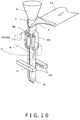
- the packaging machine is, as shown in the general configuration drawing of FIG. 10 for example, equipped with a hopper H into which the product is fed, a cylinder C that is connected to an open portion in the lower end of the hopper H, a former F that wraps a long film sheet FS around the cylinder C to thereby form the film sheet FS into a tube, a pair of pull-down belts PB that pull down the tubular film TF under the former F, a vertical sealing unit VS that heat-seals a vertical seam of the tubular film TF, and a horizontal sealing unit HS that forms horizontal seals in the tubular film TF and simultaneously seals the upper portion of a bag B filled with the product and the bottom portion of the next bag.
- a machine where a cover that covers the heated part HB of the vertical sealing unit exposed to the worker side is movably provided, during operation the cover is retracted to the side of the heated part HB, and during maintenance the cover is moved over the heated part HB.
- this kind of machine has had the problem of increased cost because it requires a sensor that detects that the vertical sealing unit VS has been opened and a drive mechanism that causes the cover to cover the heated part HB on the basis of the detection signal of the sensor.
- the vertical seal portion of the bag is a fin seal
- a pair of sealing jaws that sandwich and heat-seal the seam of the tubular film are used as the vertical sealing unit VS
- the aforementioned drive mechanism is activated and the sealing jaws become covered with the cover, so there has been the problem that maintenance of the sealing jaws cannot be performed unless a tool is used to detach the cover.
- the medicine packaging machine disclosed in patent document 1 JP-A No. 2012-126460 ) is configured in such a way that when one of a pair of sealing members moves toward the other sealing member, a cover that had covered the one sealing member is pushed by the other sealing member and retracts, and when these sealing members move away from each other, the cover that had retracted returns to its original position and covers the one sealing member, so the machine has the advantage that the aforementioned sensor and drive mechanism do not need to be provided.
- the cover is automatically returned by a spring from the position in which it exposed the sealing member to the position in which it covers the sealing member, so the machine has the advantage that during maintenance the cover can be manually opened to expose the sealing member even without using a tool.
- patent document 1 has a basic configuration different from that of a vertical sealing unit of a bag-making and packaging machine, so it has the problem that it cannot be applied as is to the vertical sealing unit of a bag-making and packaging machine. That is, the vertical sealing unit equipped with the heating belt HB of FIG. 10 does not have a member corresponding to the fixed-side sealing member, so it cannot utilize the technology of patent document 1 as is.
- the present invention has been developed in light of these kinds of issues, and it is a problem thereof to provide a packaging machine equipped with a novel safety device with which a heated part of a vertical sealing unit is covered with a cover just by retracting the vertical sealing unit to a machine side portion even without using the aforementioned drive mechanism.
- a packaging machine pertaining to the present invention includes: a vertical sealing unit that is provided so as to be retractable from a vertical sealing position for tubular film; a cover that covers a heated part of the vertical sealing unit; and a linkage mechanism that transmits the retracting movement of the vertical sealing unit to the cover to thereby cause the cover to move from a position in which it exposes the heated part to a position in which it covers the heated part.
- the vertical sealing unit is attached, so as to be rotatable in the horizontal direction, to a machine side portion, and by rotating the unit in the horizontal direction, the unit can be retracted to the machine side portion.
- the linkage mechanism be configured by a parallel linkage and that the cover be attached to a swinging end of the parallel linkage.
- the cover translationally moves between the position in which it covers the heated part of the vertical sealing unit and the position in which it exposes the heated part.
- one lever configuring the parallel linkage be equipped with a swinging end which extends further from a rotational pin that supports and allows the one lever to rotate and which swings in the opposite direction of the direction in which the cover moves.
- an actuating rod be coupled between the swinging end and the machine side portion and that, when the worker manually rotates the vertical sealing unit, the actuating rod transmit the rotating movement of the vertical sealing unit to the lever to thereby cause the lever to rotate.
- the cover coupled to the parallel linkage is moved by the swinging of the parallel linkage to cover the heated part of the vertical sealing unit.
- a packaging machine that is safe, even when the vertical sealing unit is opened from the machine body and the heated part of the vertical sealing unit is exposed to the worker side, because of the cover that covers the heated part.
- a machine that is inexpensive because a sensor and/or a drive mechanism is not used to move the cover.
- the cover be coupled via a hinge to the linkage mechanism and that the hinge be switchable between a posture in which it covers the heated part with the cover and a posture in which it flips up the cover from there to expose the heated part.
- the cover can be manually flipped up to expose the heated part, so sealing defects can be prevented by adjusting the alignment of the heated part and/or cleaning the heated part.
- the hinge be equipped with a spring that returns the cover flipped up from the heated part to its original position. Because of this, accidents caused by forgetting to close the cover after maintenance can be prevented.
- the vertical sealing unit may be equipped with a pair of sealing jaws that move toward and away from each other and may sandwich between the sealing jaws and heat-seal the seam of the tubular film.
- the vertical sealing unit used in the present invention is not limited to this and may, for example, be a vertical sealing unit that presses a circulating heating belt against and heat-seals the seam of the tubular film while continuously pulling down the tubular film.
- a driver that causes the sealing jaws to move toward and away from each other be disposed on one side of the sealing jaws and that the linkage mechanism be disposed on the other side.
- the driver and the linkage mechanism are disposed apart from each other on both sides of the pair of sealing jaws in the vertical sealing unit, so the present invention can also be easily incorporated into an existing vertical sealing unit.
- the cover when the worker moves the vertical sealing unit to the retracted position, in conjunction with that movement the cover covers the heated part of the vertical sealing unit, so there can be provided a packaging machine that is safe when replacing the former and/or the film. Furthermore, there can be provided a safety device that is inexpensive because the machine does not require a sensor and/or a drive mechanism as in the conventional machine.
- the cover that covers the heated part is coupled via the hinge to the linkage mechanism, so by manually flipping up the cover to expose the heated part during maintenance, the alignment of the heated part can be adjusted, and the heated part can be cleaned, in that state. Consequently, it is not necessary to use a tool to detach the cover, so workability is improved and, because of that, problems in the sealing by the vertical sealing unit can be prevented.
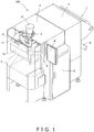
- FIG. 1 shows an external perspective view of the embodiment of the packaging machine pertaining to the present invention.
- a packaging machine 100 is equipped with a film roll housing section 1 in its rear portion, a bag-making and packaging section 2 in its front portion, a cover member 3 attached to the front surface side of the bag-making and packaging section 2, an operation unit 4 equipped with a touch panel of a machine side portion 8, and an electrical control box 5 that controls a switchboard and the machine overall.
- the film roll housing section 1 is equipped with a support mechanism 6 that supports a film roll, a splicer 7 which, when the film wound in the film roll runs out, splices the leading end portion of the subsequent film to the trailing end portion of the preceding film, and a dancer roller-not shown in the drawings-that controls abrupt fluctuations in tension during film conveyance.
- the bag-making and packaging section 2 is equipped with a hopper H into which product is fed, a cylinder C that is connected to an open portion in the lower end of the hopper H, a former F that wraps a film sheet around the cylinder C to thereby form the film sheet into a tube (see FIG. 10 ), a right and left pair of pull-down belts PB that pull down the tubular film under the former F (see FIG. 10 ), a vertical sealing unit 10 that heat-seals the seam of both vertical direction sides of the tubular film, and the horizontal sealing unit HS of FIG.
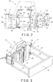
- FIG. 2 is a perspective view, as seen from the front side, showing a state when the right end of the vertical sealing unit 10 has been slightly opened from the machine body;
- FIG. 3 is an external perspective view, as seen from the machine side, showing a state when the vertical sealing unit 10 has been closed to the machine body;
- FIG. 4 is an external perspective view, as seen from the machine side, showing a state when the vertical sealing unit 10 has been further opened 45 degrees.
- the vertical sealing unit 10 is attached, so as to be rotatable in a horizontal plane, via a hinge 11 to the machine side portion 8 of FIG. 1 .
- the hinge 11 is disposed on the left side of the page in FIG. 2 and on the right side of the page in FIG. 3 and FIG. 4 , but there are also cases where the hinge 11 is disposed on the opposite sides.
- the hinge 11 is configured by a fixed block 13 that is attached to the machine side portion 8, a movable block 14 that is attached to the vertical sealing unit 10, and a vertical rotational pin 15 (see FIG. 5 to FIG. 7 ) that rotatably intercouples the blocks 13 and 14.
- the fixed block 13 is secured to distal end portions of parallel shafts 12 that serve as a machine frame of the machine side portion 8. Consequently, the vertical sealing unit 10 rotates in the horizontal direction about the rotational pin 15.
- FIG. 2 parallel support shafts 16 that extend in the horizontal direction are secured to the movable block 14 on the vertical sealing unit 10 side, and a single plate 17 is screwed to the right-side end portions of the support shafts 16. Because of this, the upper and lower support shafts 16 are integrated by the plate 17. Furthermore, a mounting plate 18 that is U-shaped as seen in a plan view is disposed in the middle of the support shafts 16, cutouts 19 into which the support shafts 16 fit from the horizontal direction are formed in both side surfaces of the mounting plate 18, and slit collars 20 through which the support shafts 16 are passed are screwed to peripheral edges of the cutouts 19.
- a pair of sealing jaws 21 are disposed in the vertical direction on the reverse side of the mounting plate 18, and the position at which the mounting plate 18 is attached to the parallel shafts 16 is adjusted in such a way that meshing surfaces of the sealing jaws 21 are aligned with mating surfaces of the tubular film. That is, the right and left direction position of the mounting plate 18 is adjusted by loosening the slit collars 20, and when the position is decided, the slit collars 20 are tightened to secure them to the support shafts 16.
- bent portions 23 for attaching a lever handle 22 are formed in both front and rear direction side surfaces of the right-side plate 17, and a rotating shaft 24 of the lever handle 22 is passed through the bent portions 23. Furthermore, a tongue piece 26 that catches on a plate 25 of the machine side portion 8 is attached to the distal end portion of the rotating shaft 24; when the lever handle 22 pointing in the vertical direction in FIG. 2 is turned in the horizontal direction, the tongue piece 24 rotates and comes away from the plate 25, and when the lever handle 22 is pulled forward in that state, the vertical sealing unit 10 can be opened forward about the hinge 11.
- the plate 25 on which the tongue piece 26 catches vertically bridges the distal end portions of the parallel shafts 12 disposed in the machine side portion 8 on the opposite side of the hinge 11.
- the pair of sealing jaws 21, air cylinders 27 serving as drivers that move one sealing jaw 21 toward and away from the other sealing jaw 21, and a support block 28 to which the air cylinders 27 are secured.
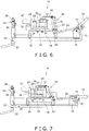
- FIG. 5 is a bottom view of the vertical sealing unit 10, as seen from its bottom, when the vertical sealing unit 10 is closed to the machine body;
- FIG. 6 is a bottom view showing a state in which the vertical sealing unit 10 has been opened 45 degrees with respect to the parallel shafts 12;
- FIG. 7 is a bottom view showing a state in which the unit 10 has been further opened to 90 degrees.
- the support block 28 for the air cylinders 27 has a U-shape as seen in a plan view, the air cylinders 27 serving as drivers are attached to one side surface of the block 28, and one sealing jaw 21 is attached via a movable block 30 to distal end portions of piston rods 29 of the air cylinders 27. Furthermore, the other sealing jaw 21 that meshes with that sealing jaw 21 is secured to the other side surface of the support block 28.
- a cover 40 that covers the pair of sealing jaws 21 (a heated part) that become heated
- a linkage mechanism 50 that translationally moves the cover 40 between a position in which it covers the heated part and a position in which it exposes the heated part
- an actuating rod 60 that rotates the linkage mechanism 50 in conjunction with the rotation of the vertical sealing unit 10.
- FIG. 8 shows an enlarged view of the cover 40 and the linkage mechanism 50
- FIG. 9 shows a partial perspective view in a state in which the cover 40 attached via a hinge 42 to the linkage mechanism 50 has been flipped up in a direction away from the sealing jaws 21.
- the cover 40 is formed of a plate with a size that completely covers the sealing jaws 21 that become heated.
- the linkage mechanism 50 is what is called a quadric-chain parallel linkage, with fixed-side rotational pins 51a and 52a of levers 51 and 52 being rotatably attached to brackets 53 secured to the mounting plate 18 and with swinging-side rotational pins 51b and 52b of the levers 51 and 52 being likewise rotatably attached to a bracket 41 attached to the reverse surface side of the cover 40.
- one lever 51 is equipped with a swinging end 54 that extends beyond the fixed-side rotational pin 51a toward the opposite side and swings in the opposite direction of the cover 40, and one end of the actuating rod 60 is attached via a rod end bearing 61 to the swinging end 54.
- the other end portion of the actuating rod 60 is likewise attached via a rod end bearing 62 to the fixed block 13 of the machine side portion 8. Consequently, when the vertical sealing unit 10 rotates in the horizontal direction so that the actuating rod 60 is pulled in the opposite direction, the swinging end 54 of the lever 51 rotates in the counterclockwise direction, so the cover 40 moves leftward and moves toward a position in which it covers the pair of sealing jaws 21.
- the bracket 41 coupled to each set of the two levers 51 and 52 disposed on the right and left sides thereof is disposed on the reverse surface side of the cover 40, and the cover 40 is attached via the hinge 42 to the bracket 41. Consequently, the cover 40 is coupled via the hinge 42 and the bracket 41 to the swinging end of the linkage mechanism 50, so even if during maintenance the cover 40 is in the position in which it covers the sealing jaws 21, the sealing jaws 21 can be exposed by manually flipping up the cover 40. Because of this, sealing defects can be prevented by adjusting the alignment between the pair of sealing jaws 21 and/or cleaning the meshing surfaces of the sealing jaws 21 without detaching the cover 40.
- the hinge 42 is equipped with a return spring not shown in the drawings. Because of this, when maintenance is finished, the cover 40 is automatically returned by the spring to the position in which it covers the sealing jaws 21, so accidents caused by forgetting to close the flipped-up cover 40 can be prevented.
- the linkage mechanism 50 is provided on the side where the air cylinders 27 are not disposed, so there is nothing to hinder the translational movement of the cover 40, and even when the vertical sealing unit 10 is set in the vertical sealing position in the machine body, the linkage mechanism 50 does not interfere with the tubular film TF. Consequently, it becomes easy to incorporate a safety device configured from the cover 40, the linkage mechanism 50, and the actuating rod 60 into an existing vertical sealing unit.
- the vertical sealing unit is configured to be rotated in the horizontal direction, but the vertical sealing unit can also be configured to be translationally moved via a linkage.
- the vertical sealing unit employs a system where the seam of the tubular film is sandwiched between and sealed by the pair of sealing jaws 21, but instead of this the vertical sealing unit may also be a vertical sealing unit equipped with a circulating type of heating belt such as shown in FIG. 10 .
- the air cylinders that cause the pair of sealing jaws to move toward and away from each other become unnecessary, so the vertical sealing unit 10 can be given a simple configuration.
- the cover is configured as a dome or a tunnel rather than a plate so that it widely covers the heating belt while following a circular arc.
- Patent Document 1 JP-ANo. 2012-126460
Landscapes
- Engineering & Computer Science (AREA)
- Mechanical Engineering (AREA)
- Package Closures (AREA)
- Containers And Plastic Fillers For Packaging (AREA)
Abstract
Description
- The present invention relates to a safety device that protects a worker from a heated part of a vertical sealing unit when performing maintenance on a packaging machine.
- As a packaging machine that forms bags from a long film and simultaneously fills the bags with product, there is a bag-making and packaging machine.
- The packaging machine is, as shown in the general configuration drawing of
FIG. 10 for example, equipped with a hopper H into which the product is fed, a cylinder C that is connected to an open portion in the lower end of the hopper H, a former F that wraps a long film sheet FS around the cylinder C to thereby form the film sheet FS into a tube, a pair of pull-down belts PB that pull down the tubular film TF under the former F, a vertical sealing unit VS that heat-seals a vertical seam of the tubular film TF, and a horizontal sealing unit HS that forms horizontal seals in the tubular film TF and simultaneously seals the upper portion of a bag B filled with the product and the bottom portion of the next bag. - In this kind of packaging machine, when replacing the former F and/or the film sheet FS, a worker stops the machine, thereafter moves the pull-down belts PB and the vertical sealing unit VS back from the tubular film TF, then opens the vertical sealing unit VS in the direction of the arrow together with a protective cover K indicated by the dashed lines, and removes the tubular film TF and/or detaches the former F. At that time, a heated part HB of the vertical sealing unit VS becomes exposed to the worker side, so the worker can touch the heated part HB and sustain a burn injury.
- Therefore, a machine is known where a cover that covers the heated part HB of the vertical sealing unit exposed to the worker side is movably provided, during operation the cover is retracted to the side of the heated part HB, and during maintenance the cover is moved over the heated part HB.
- However, this kind of machine has had the problem of increased cost because it requires a sensor that detects that the vertical sealing unit VS has been opened and a drive mechanism that causes the cover to cover the heated part HB on the basis of the detection signal of the sensor.
- Furthermore, when the vertical seal portion of the bag is a fin seal, a pair of sealing jaws that sandwich and heat-seal the seam of the tubular film are used as the vertical sealing unit VS, but when the vertical sealing unit is opened when performing maintenance on the sealing jaws, the aforementioned drive mechanism is activated and the sealing jaws become covered with the cover, so there has been the problem that maintenance of the sealing jaws cannot be performed unless a tool is used to detach the cover.
- To address this, the medicine packaging machine disclosed in patent document 1 (
JP-A No. 2012-126460 - However, the technology of patent document 1 has a basic configuration different from that of a vertical sealing unit of a bag-making and packaging machine, so it has the problem that it cannot be applied as is to the vertical sealing unit of a bag-making and packaging machine. That is, the vertical sealing unit equipped with the heating belt HB of
FIG. 10 does not have a member corresponding to the fixed-side sealing member, so it cannot utilize the technology of patent document 1 as is. Furthermore, although there is also a vertical sealing unit that sandwiches between a pair of sealing jaws and heat-seals the seam of the film in the same way as the technology of patent document 1, when the unit is opened the pair of sealing jaws remain stopped, so as in patent document 1, even if the worker were to try to move the cover by moving one sealing jaw toward and away from the other sealing jaw, it cannot be done. - The present invention has been developed in light of these kinds of issues, and it is a problem thereof to provide a packaging machine equipped with a novel safety device with which a heated part of a vertical sealing unit is covered with a cover just by retracting the vertical sealing unit to a machine side portion even without using the aforementioned drive mechanism.
- Furthermore, it is a problem of the present invention to provide a novel packaging machine which, when using sealing jaws as the vertical sealing unit, also allows easy maintenance of the sealing jaws covered with the cover.
- A packaging machine pertaining to the present invention includes: a vertical sealing unit that is provided so as to be retractable from a vertical sealing position for tubular film; a cover that covers a heated part of the vertical sealing unit; and a linkage mechanism that transmits the retracting movement of the vertical sealing unit to the cover to thereby cause the cover to move from a position in which it exposes the heated part to a position in which it covers the heated part.
- The vertical sealing unit is attached, so as to be rotatable in the horizontal direction, to a machine side portion, and by rotating the unit in the horizontal direction, the unit can be retracted to the machine side portion.
- Furthermore, it is preferred that the linkage mechanism be configured by a parallel linkage and that the cover be attached to a swinging end of the parallel linkage. In this case, when the parallel linkage swings, the cover translationally moves between the position in which it covers the heated part of the vertical sealing unit and the position in which it exposes the heated part.
- Furthermore, it is preferred that one lever configuring the parallel linkage be equipped with a swinging end which extends further from a rotational pin that supports and allows the one lever to rotate and which swings in the opposite direction of the direction in which the cover moves. Furthermore, it is preferred that an actuating rod be coupled between the swinging end and the machine side portion and that, when the worker manually rotates the vertical sealing unit, the actuating rod transmit the rotating movement of the vertical sealing unit to the lever to thereby cause the lever to rotate. In this case, the cover coupled to the parallel linkage is moved by the swinging of the parallel linkage to cover the heated part of the vertical sealing unit. Because of this, there can be provided a packaging machine that is safe, even when the vertical sealing unit is opened from the machine body and the heated part of the vertical sealing unit is exposed to the worker side, because of the cover that covers the heated part. Moreover, there can be provided a machine that is inexpensive because a sensor and/or a drive mechanism is not used to move the cover.
- Furthermore, it is preferred that the cover be coupled via a hinge to the linkage mechanism and that the hinge be switchable between a posture in which it covers the heated part with the cover and a posture in which it flips up the cover from there to expose the heated part. In this case, even if the heated part of the vertical sealing unit is covered with the cover during maintenance, the cover can be manually flipped up to expose the heated part, so sealing defects can be prevented by adjusting the alignment of the heated part and/or cleaning the heated part.
- Furthermore, it is preferred that the hinge be equipped with a spring that returns the cover flipped up from the heated part to its original position. Because of this, accidents caused by forgetting to close the cover after maintenance can be prevented.
- Furthermore, the vertical sealing unit may be equipped with a pair of sealing jaws that move toward and away from each other and may sandwich between the sealing jaws and heat-seal the seam of the tubular film. However, the vertical sealing unit used in the present invention is not limited to this and may, for example, be a vertical sealing unit that presses a circulating heating belt against and heat-seals the seam of the tubular film while continuously pulling down the tubular film.
- In a case where the vertical sealing unit is equipped with the pair of sealing jaws, it is preferred that a driver that causes the sealing jaws to move toward and away from each other be disposed on one side of the sealing jaws and that the linkage mechanism be disposed on the other side.
- Because of this, the driver and the linkage mechanism are disposed apart from each other on both sides of the pair of sealing jaws in the vertical sealing unit, so the present invention can also be easily incorporated into an existing vertical sealing unit.
- According to the present invention, when the worker moves the vertical sealing unit to the retracted position, in conjunction with that movement the cover covers the heated part of the vertical sealing unit, so there can be provided a packaging machine that is safe when replacing the former and/or the film. Furthermore, there can be provided a safety device that is inexpensive because the machine does not require a sensor and/or a drive mechanism as in the conventional machine.
- Moreover, the cover that covers the heated part is coupled via the hinge to the linkage mechanism, so by manually flipping up the cover to expose the heated part during maintenance, the alignment of the heated part can be adjusted, and the heated part can be cleaned, in that state. Consequently, it is not necessary to use a tool to detach the cover, so workability is improved and, because of that, problems in the sealing by the vertical sealing unit can be prevented.
-
-
FIG. 1 is an overall perspective view of a packaging machine pertaining to an embodiment of the present invention. -
FIG. 2 is a perspective view from the front side showing a state in which a vertical sealing unit of the packaging machine has been slightly opened. -
FIG. 3 is an external perspective view of the vertical sealing unit ofFIG. 2 as seen from the machine body side. -
FIG. 4 is an external perspective view showing a state in which the vertical sealing unit ofFIG. 3 has been opened 45 degrees. -
FIG. 5 is a bottom view of the vertical sealing unit ofFIG. 3 as seen from its bottom side. -
FIG. 6 is a bottom view showing a state in which the vertical sealing unit ofFIG. 5 has been opened 45 degrees. -
FIG. 7 is a bottom view showing a state in which the vertical sealing unit ofFIG. 5 has been opened 90 degrees. -
FIG. 8 is an enlarged view of a cover and a linkage mechanism. -
FIG. 9 is an enlarged perspective view showing a state in which the cover is attached via a hinge to the linkage mechanism. -
FIG. 10 is a configural explanatory drawing for describing the basic configuration of a conventional packaging machine. - A packaging machine pertaining to an embodiment of the present invention will be described below with reference to the drawings. It will be noted that the embodiment described below is not intended to limit the technical scope of the present invention.
-
FIG. 1 shows an external perspective view of the embodiment of the packaging machine pertaining to the present invention. In this drawing, apackaging machine 100 is equipped with a film roll housing section 1 in its rear portion, a bag-making andpackaging section 2 in its front portion, acover member 3 attached to the front surface side of the bag-making andpackaging section 2, anoperation unit 4 equipped with a touch panel of amachine side portion 8, and anelectrical control box 5 that controls a switchboard and the machine overall. - The film roll housing section 1 is equipped with a
support mechanism 6 that supports a film roll, asplicer 7 which, when the film wound in the film roll runs out, splices the leading end portion of the subsequent film to the trailing end portion of the preceding film, and a dancer roller-not shown in the drawings-that controls abrupt fluctuations in tension during film conveyance. - Housed in the bag-making and
packaging section 2 are the basic constituent elements ofFIG. 10 . That is, the bag-making andpackaging section 2 is equipped with a hopper H into which product is fed, a cylinder C that is connected to an open portion in the lower end of the hopper H, a former F that wraps a film sheet around the cylinder C to thereby form the film sheet into a tube (seeFIG. 10 ), a right and left pair of pull-down belts PB that pull down the tubular film under the former F (seeFIG. 10 ), avertical sealing unit 10 that heat-seals the seam of both vertical direction sides of the tubular film, and the horizontal sealing unit HS ofFIG. 10 that forms horizontal seals in the tubular film under thevertical sealing unit 10 and simultaneously horizontally seals and cuts the upper portion of the bag filled with the product and the bottom portion of the next bag. Furthermore, the film sheet paid out via the aforementioned dancer roller is guided to the former F ofFIG. 10 , and there it is formed into the tubular film. -
FIG. 2 is a perspective view, as seen from the front side, showing a state when the right end of thevertical sealing unit 10 has been slightly opened from the machine body;FIG. 3 is an external perspective view, as seen from the machine side, showing a state when thevertical sealing unit 10 has been closed to the machine body; andFIG. 4 is an external perspective view, as seen from the machine side, showing a state when thevertical sealing unit 10 has been further opened 45 degrees. - In these drawings the
vertical sealing unit 10 is attached, so as to be rotatable in a horizontal plane, via ahinge 11 to themachine side portion 8 ofFIG. 1 . Thehinge 11 is disposed on the left side of the page inFIG. 2 and on the right side of the page inFIG. 3 andFIG. 4 , but there are also cases where thehinge 11 is disposed on the opposite sides. - The
hinge 11 is configured by afixed block 13 that is attached to themachine side portion 8, amovable block 14 that is attached to thevertical sealing unit 10, and a vertical rotational pin 15 (seeFIG. 5 to FIG. 7 ) that rotatably intercouples theblocks fixed block 13 is secured to distal end portions ofparallel shafts 12 that serve as a machine frame of themachine side portion 8. Consequently, thevertical sealing unit 10 rotates in the horizontal direction about therotational pin 15. - In
FIG. 2 ,parallel support shafts 16 that extend in the horizontal direction are secured to themovable block 14 on thevertical sealing unit 10 side, and asingle plate 17 is screwed to the right-side end portions of thesupport shafts 16. Because of this, the upper andlower support shafts 16 are integrated by theplate 17. Furthermore, a mountingplate 18 that is U-shaped as seen in a plan view is disposed in the middle of thesupport shafts 16,cutouts 19 into which thesupport shafts 16 fit from the horizontal direction are formed in both side surfaces of the mountingplate 18, and slitcollars 20 through which thesupport shafts 16 are passed are screwed to peripheral edges of thecutouts 19. - Furthermore, a pair of sealing
jaws 21 are disposed in the vertical direction on the reverse side of the mountingplate 18, and the position at which the mountingplate 18 is attached to theparallel shafts 16 is adjusted in such a way that meshing surfaces of the sealingjaws 21 are aligned with mating surfaces of the tubular film. That is, the right and left direction position of the mountingplate 18 is adjusted by loosening theslit collars 20, and when the position is decided, theslit collars 20 are tightened to secure them to thesupport shafts 16. - Furthermore,
bent portions 23 for attaching alever handle 22 are formed in both front and rear direction side surfaces of the right-side plate 17, and arotating shaft 24 of the lever handle 22 is passed through thebent portions 23. Furthermore, atongue piece 26 that catches on aplate 25 of themachine side portion 8 is attached to the distal end portion of therotating shaft 24; when the lever handle 22 pointing in the vertical direction inFIG. 2 is turned in the horizontal direction, thetongue piece 24 rotates and comes away from theplate 25, and when the lever handle 22 is pulled forward in that state, thevertical sealing unit 10 can be opened forward about thehinge 11. - It will be noted that the
plate 25 on which thetongue piece 26 catches vertically bridges the distal end portions of theparallel shafts 12 disposed in themachine side portion 8 on the opposite side of thehinge 11. - Provided on the reverse side (machine side) of the mounting
plate 18 inFIG. 3 andFIG. 4 are the pair of sealingjaws 21,air cylinders 27 serving as drivers that move one sealingjaw 21 toward and away from the other sealingjaw 21, and asupport block 28 to which theair cylinders 27 are secured. -
FIG. 5 is a bottom view of thevertical sealing unit 10, as seen from its bottom, when thevertical sealing unit 10 is closed to the machine body;FIG. 6 is a bottom view showing a state in which thevertical sealing unit 10 has been opened 45 degrees with respect to theparallel shafts 12; andFIG. 7 is a bottom view showing a state in which theunit 10 has been further opened to 90 degrees. - In these drawings, the
support block 28 for theair cylinders 27 has a U-shape as seen in a plan view, theair cylinders 27 serving as drivers are attached to one side surface of theblock 28, and one sealingjaw 21 is attached via amovable block 30 to distal end portions ofpiston rods 29 of theair cylinders 27. Furthermore, the other sealingjaw 21 that meshes with that sealingjaw 21 is secured to the other side surface of thesupport block 28. - A
linear bush 31 is attached, parallel to thepiston rods 29, to the lower portion of themovable block 30, and aguide rod 32 is slidably inserted through thebush 31. Furthermore, both end portions of theguide rod 32 are secured to side surfaces on both sides of thesupport block 28. Additionally, when thepiston rods 29 of theair cylinders 27 move in the directions of the arrows, themovable block 30 is guided by theguide rod 32 and reciprocally moves. Consequently, when thepiston rods 29 of theair cylinders 27 move backward, the pair of sealingjaws 21 open, and when thepiston rods 29 move forward, the sealingjaws 21 close and mesh with a predetermined pressure. It will be noted that thesupport block 28 is secured to the reverse surface of the mountingplate 18 via arectangular block 33. - Provided in the
vertical sealing unit 10 inFIG. 5 to FIG. 8 are acover 40 that covers the pair of sealing jaws 21 (a heated part) that become heated, alinkage mechanism 50 that translationally moves thecover 40 between a position in which it covers the heated part and a position in which it exposes the heated part, and anactuating rod 60 that rotates thelinkage mechanism 50 in conjunction with the rotation of thevertical sealing unit 10. -
FIG. 8 shows an enlarged view of thecover 40 and thelinkage mechanism 50, andFIG. 9 shows a partial perspective view in a state in which thecover 40 attached via ahinge 42 to thelinkage mechanism 50 has been flipped up in a direction away from the sealingjaws 21. In these drawings, thecover 40 is formed of a plate with a size that completely covers the sealingjaws 21 that become heated. Thelinkage mechanism 50 is what is called a quadric-chain parallel linkage, with fixed-siderotational pins levers brackets 53 secured to the mountingplate 18 and with swinging-siderotational pins levers bracket 41 attached to the reverse surface side of thecover 40. - Furthermore, one
lever 51 is equipped with a swingingend 54 that extends beyond the fixed-siderotational pin 51a toward the opposite side and swings in the opposite direction of thecover 40, and one end of the actuatingrod 60 is attached via a rod end bearing 61 to the swingingend 54. The other end portion of the actuatingrod 60 is likewise attached via a rod end bearing 62 to the fixedblock 13 of themachine side portion 8. Consequently, when thevertical sealing unit 10 rotates in the horizontal direction so that the actuatingrod 60 is pulled in the opposite direction, the swingingend 54 of thelever 51 rotates in the counterclockwise direction, so thecover 40 moves leftward and moves toward a position in which it covers the pair of sealingjaws 21. - Consequently, when the
vertical sealing unit 10 is in the vertical sealing position, that is, in a state in which thevertical sealing unit 10 is closed to the machine body side, thecover 40 is retracted to the side of the sealingjaws 21 as shown inFIG. 5 . From this state, when the worker turns the lever handle 22 to unlock it from theplate 25 and then pulls the lever handle 22 forward to rotate thevertical sealing unit 10 toward themachine side portion 8, in conjunction with that movement thecover 40 that had been on the side of the sealingjaws 21 is pulled by the actuatingrod 60 and moves toward the position in which it covers the sealingjaws 21 as shown inFIG. 6 . Then, as shown inFIG. 7 , when the worker opens thevertical sealing unit 10 90 degrees, thecover 40 reaches a position in which it completely covers the heated part of the sealingjaws 21. The length of each link of thelinkage mechanism 50 as well as the length of the actuatingrod 60 and the attachment positions thereof are decided in such a way that this movement and positional relationship are obtained. - In
FIG. 9 , thebracket 41 coupled to each set of the twolevers cover 40, and thecover 40 is attached via thehinge 42 to thebracket 41. Consequently, thecover 40 is coupled via thehinge 42 and thebracket 41 to the swinging end of thelinkage mechanism 50, so even if during maintenance thecover 40 is in the position in which it covers the sealingjaws 21, the sealingjaws 21 can be exposed by manually flipping up thecover 40. Because of this, sealing defects can be prevented by adjusting the alignment between the pair of sealingjaws 21 and/or cleaning the meshing surfaces of the sealingjaws 21 without detaching thecover 40. - Furthermore, the
hinge 42 is equipped with a return spring not shown in the drawings. Because of this, when maintenance is finished, thecover 40 is automatically returned by the spring to the position in which it covers the sealingjaws 21, so accidents caused by forgetting to close the flipped-upcover 40 can be prevented. - Furthermore, the
linkage mechanism 50 is provided on the side where theair cylinders 27 are not disposed, so there is nothing to hinder the translational movement of thecover 40, and even when thevertical sealing unit 10 is set in the vertical sealing position in the machine body, thelinkage mechanism 50 does not interfere with the tubular film TF. Consequently, it becomes easy to incorporate a safety device configured from thecover 40, thelinkage mechanism 50, and theactuating rod 60 into an existing vertical sealing unit. - An embodiment of the present invention has been described above, but the present invention is not limited to this and can also employ other configurations. For example, in the embodiment, the vertical sealing unit is configured to be rotated in the horizontal direction, but the vertical sealing unit can also be configured to be translationally moved via a linkage. Furthermore, the vertical sealing unit employs a system where the seam of the tubular film is sandwiched between and sealed by the pair of sealing
jaws 21, but instead of this the vertical sealing unit may also be a vertical sealing unit equipped with a circulating type of heating belt such as shown inFIG. 10 . In this case, the air cylinders that cause the pair of sealing jaws to move toward and away from each other become unnecessary, so thevertical sealing unit 10 can be given a simple configuration. Furthermore, when using the heating belt, the inside heater part around which the heating belt travels is also exposed to the worker side, so the cover is configured as a dome or a tunnel rather than a plate so that it widely covers the heating belt while following a circular arc. -
- TF
- Tubular Film
- 8
- Machine Side Portion
- 10
- Vertical Sealing Unit
- 21
- Sealing Jaws (Heated Part)
- 27
- Air Cylinders (Drivers)
- 40
- Cover
- 42
- Hinge
- 50
- Linkage Mechanism
- 51
- One Lever
- 51a
- Rotational Pin
- 54
- Swinging End
- 60
- Actuating Rod
- 100
- Packaging Machine
- Patent Document 1:
JP-ANo. 2012-126460
Claims (6)
- A packaging machine comprising:a vertical sealing unit that is provided so as to be retractable from a vertical sealing position for tubular film;a movable cover that covers a heated part of the vertical sealing unit; anda linkage mechanism that transmits the retracting movement of the vertical sealing unit to the cover to thereby cause the cover to move from a position in which it exposes the heated part to a position in which it covers the heated part.
- The packaging machine according to claim 1, wherein
the vertical sealing unit is attached, so as to be rotatable in the horizontal direction, to a machine side portion,
the linkage mechanism is configured by a parallel linkage, and
the cover is attached to a swinging end of the parallel linkage. - The packaging machine according to claim 2, wherein
one lever configuring the parallel linkage is equipped with a swinging end which extends further from a rotational pin that allows the lever to rotate and which swings in the opposite direction of the cover,
an actuating rod is coupled between the swinging end and the machine side portion, and
when the vertical sealing unit rotates toward the machine side portion the actuating rod transmits the rotating movement of the vertical sealing unit to the lever to thereby cause the lever to rotate. - The packaging machine according to any of claims 1 to 3, wherein
the cover is coupled via a hinge to the linkage mechanism, and
the hinge is switchable between a posture in which it covers the heated part with the cover and a posture in which it flips up the cover from there to expose the heated part. - The packaging machine according to claim 4, wherein the hinge is equipped with a spring that returns the cover flipped up from the heated part to its original position.
- The packaging machine according to claim 1 or 2, wherein
the vertical sealing unit is equipped with a pair of sealing jaws that move toward and away from each other,
a driver that causes the sealing jaws to move toward and away from each other is disposed on one side of the sealing jaws, and
the linkage mechanism is disposed on the other side.
Applications Claiming Priority (2)
| Application Number | Priority Date | Filing Date | Title |
|---|---|---|---|
| JP2016090442A JP6742625B2 (en) | 2016-04-28 | 2016-04-28 | Packaging equipment |
| PCT/JP2017/008673 WO2017187788A1 (en) | 2016-04-28 | 2017-03-06 | Packaging device |
Publications (3)
| Publication Number | Publication Date |
|---|---|
| EP3450335A1 true EP3450335A1 (en) | 2019-03-06 |
| EP3450335A4 EP3450335A4 (en) | 2019-03-13 |
| EP3450335B1 EP3450335B1 (en) | 2020-01-22 |
Family
ID=60161380
Family Applications (1)
| Application Number | Title | Priority Date | Filing Date |
|---|---|---|---|
| EP17789077.9A Active EP3450335B1 (en) | 2016-04-28 | 2017-03-06 | Packaging device |
Country Status (6)
| Country | Link |
|---|---|
| US (1) | US10988272B2 (en) |
| EP (1) | EP3450335B1 (en) |
| JP (1) | JP6742625B2 (en) |
| CN (1) | CN109071056B (en) |
| AU (1) | AU2017257034B2 (en) |
| WO (1) | WO2017187788A1 (en) |
Families Citing this family (11)
| Publication number | Priority date | Publication date | Assignee | Title |
|---|---|---|---|---|
| DE102017128363A1 (en) * | 2017-11-30 | 2019-06-06 | Multivac Sepp Haggenmüller Se & Co. Kg | PACKAGING MACHINE WITH FOLDABLE GUARD COVER |
| JP7324489B2 (en) * | 2019-06-04 | 2023-08-10 | 株式会社川島製作所 | Vertical sealing device in a vertical form-fill-seal machine |
| JP7294652B2 (en) * | 2019-08-14 | 2023-06-20 | 株式会社川島製作所 | Vertical form-fill-seal machine with front cover and thin monitor |
| CN110394764B (en) * | 2019-09-02 | 2021-02-09 | 重庆齿轮箱有限责任公司 | Nondestructive dismounting tool for sealing element |
| JP7316658B2 (en) * | 2019-11-25 | 2023-07-28 | 株式会社川島製作所 | Vertical form-fill-seal packaging machine and shaft replacement method |
| JP7449755B2 (en) * | 2020-03-31 | 2024-03-14 | 株式会社東京自働機械製作所 | Sealing device for bag making and filling machine |
| DE102021125155A1 (en) * | 2021-09-28 | 2023-03-30 | Syntegon Technology Gmbh | Sealing device and longitudinal sealing device with such a sealing device |
| CN113928625B (en) * | 2021-11-01 | 2023-09-15 | 江苏宏芯亿泰智能装备有限公司 | Film equipment |
| CN114199463B (en) * | 2021-11-16 | 2024-06-11 | 山西欣德易新材料科技有限公司 | Detection device and method for high-efficiency dry-wet separation packaging bag |
| JP2024082383A (en) * | 2022-12-08 | 2024-06-20 | 株式会社イシダ | Bag making and packaging equipment |
| CN118753602B (en) * | 2024-09-05 | 2024-11-15 | 四川科斯特自动化设备有限公司 | A continuous packaging machine with ultrasonic sealing |
Family Cites Families (27)
| Publication number | Priority date | Publication date | Assignee | Title |
|---|---|---|---|---|
| US2934390A (en) * | 1958-11-25 | 1960-04-26 | Walter P Wright | Cabinet with built-in garbage receptacle |
| SE310618B (en) * | 1963-05-20 | 1969-05-05 | Akerlund & Rausing Ab | |
| JPH0820842B2 (en) * | 1987-12-14 | 1996-03-04 | キヤノン株式会社 | Process cartridge and image forming apparatus |
| US4996825A (en) * | 1989-01-31 | 1991-03-05 | Kliklok Corporation | Combined blousing, stripping and sealing for bag forming and method |
| US4909017B1 (en) * | 1989-07-28 | 1999-02-09 | Minigrip Inc | Reclosable bag material method and apparatus |
| JPH04247468A (en) * | 1991-02-01 | 1992-09-03 | Fuji Xerox Co Ltd | Image forming device |
| DE4313205C1 (en) * | 1993-04-22 | 1994-08-18 | Haensel Otto Gmbh | Vertically intermittently working flat-bag machine with sealing units pivotable into a setting-up and a cleaning position |
| JPH07230197A (en) * | 1994-02-17 | 1995-08-29 | Fuji Xerox Co Ltd | Image forming device |
| DE19541617A1 (en) | 1995-11-08 | 1997-05-15 | Bosch Gmbh Robert | Tube and bag making machine |
| US5852920A (en) * | 1996-11-13 | 1998-12-29 | Triangle Package Machinery Company | Longitudinal seam sealer for continuous motion form, fill and seal machine |
| JP2003291925A (en) * | 2002-04-08 | 2003-10-15 | Ibaraki Precision Mach Co Ltd | Film welding equipment |
| DE03771392T1 (en) * | 2002-07-30 | 2005-09-29 | Ishida Co., Ltd. | PACKAGING MACHINE, PACKAGING METHOD AND PACKAGING SYSTEM |
| JP2004149213A (en) * | 2002-10-30 | 2004-05-27 | Yakotekku:Kk | Sealing device for automatic packing machine |
| NL1023151C2 (en) * | 2003-01-06 | 2004-07-07 | C F S Weert B V | Device and method for manufacturing resealable packages. |
| JP2005112374A (en) * | 2003-10-06 | 2005-04-28 | Tosei Denki Kk | Heat sealing packer, and heat sealing packaging method |
| CN101665160B (en) * | 2005-05-31 | 2011-10-19 | 株式会社汤山制作所 | Medicine dispensing/packaging apparatus |
| WO2007106916A1 (en) * | 2006-03-15 | 2007-09-20 | August Egli | Continuous motion vertical form, fill and seal machine |
| JP4933180B2 (en) * | 2006-07-14 | 2012-05-16 | 株式会社川島製作所 | Bag making and packaging machine |
| JP5918980B2 (en) * | 2011-02-04 | 2016-05-18 | 株式会社イシダ | Bag making and packaging machine |
| JP5725897B2 (en) * | 2011-02-16 | 2015-05-27 | 株式会社イシダ | Packaging machine |
| US10076207B2 (en) * | 2011-03-25 | 2018-09-18 | Ping-Hua CHANG | Automatic cooking apparatus |
| AU2012201594B2 (en) | 2011-04-11 | 2016-06-23 | Tna Australia Pty Limited | A bag seal inspection device |
| DE102011075379A1 (en) | 2011-05-06 | 2012-11-08 | Robert Bosch Gmbh | Tubular bag machine and method for operating a tubular bag machine |
| US9617053B2 (en) * | 2012-06-28 | 2017-04-11 | Koninklijke Douwe Egberts B.V. | Reclosable flexible packages for food products |
| CN102717907B (en) * | 2012-07-16 | 2015-04-29 | 上海松川远亿机械设备有限公司 | Upright packaging machine |
| CN202765346U (en) * | 2012-09-20 | 2013-03-06 | 佛山市德亦宝机械制造有限公司 | Longitudinal sealing mechanism of continuous packaging machine |
| ES1135355Y (en) | 2014-12-18 | 2015-04-13 | Ulma Packaging Technological Ct S Coop | Vertical packing machine |
-
2016
- 2016-04-28 JP JP2016090442A patent/JP6742625B2/en active Active
-
2017
- 2017-03-06 US US16/095,684 patent/US10988272B2/en active Active
- 2017-03-06 AU AU2017257034A patent/AU2017257034B2/en active Active
- 2017-03-06 CN CN201780023415.2A patent/CN109071056B/en active Active
- 2017-03-06 WO PCT/JP2017/008673 patent/WO2017187788A1/en not_active Ceased
- 2017-03-06 EP EP17789077.9A patent/EP3450335B1/en active Active
Also Published As
| Publication number | Publication date |
|---|---|
| JP2017197238A (en) | 2017-11-02 |
| US10988272B2 (en) | 2021-04-27 |
| JP6742625B2 (en) | 2020-08-19 |
| AU2017257034A1 (en) | 2018-11-29 |
| EP3450335A4 (en) | 2019-03-13 |
| WO2017187788A1 (en) | 2017-11-02 |
| AU2017257034B2 (en) | 2019-07-04 |
| CN109071056A (en) | 2018-12-21 |
| EP3450335B1 (en) | 2020-01-22 |
| US20190152638A1 (en) | 2019-05-23 |
| CN109071056B (en) | 2020-06-16 |
Similar Documents
| Publication | Publication Date | Title |
|---|---|---|
| EP3450335B1 (en) | Packaging device | |
| JP2017197238A5 (en) | ||
| US4040237A (en) | Sealing jaw mechanism for package making machine | |
| DE69704542T2 (en) | Tubular bag machine | |
| DE2221310C2 (en) | Method and device for packaging objects in bags | |
| EP2683639B1 (en) | Tape cartridge | |
| US20160332755A1 (en) | Bag making and packaging machine | |
| US3650449A (en) | Intermittent feeding apparatus for a web of paper or plastics material | |
| JP2014009028A (en) | Heat seal metal fitting type automatic packing machine | |
| US20080066430A1 (en) | Continuous motion drive mechanism for a form, fill, and seal machine | |
| JP7097595B2 (en) | Bag making filling and packaging machine | |
| JP4523270B2 (en) | Vertical filling and packaging machine and film misalignment detection method in the packaging machine | |
| JP4875877B2 (en) | Bag-making device with hem | |
| JP7070878B2 (en) | Bag making filling and packaging machine with belt clearance setting function | |
| JP2005053547A (en) | Sealer for vertical filling and packaging machine, and filling and packaging machine using the same | |
| US20080163589A1 (en) | Combined packaging machine | |
| JP6453259B2 (en) | Tube film packaging mechanism | |
| JP6498948B2 (en) | Vertical sealing device for vertical bag making filling and packaging machine | |
| FI69993B (en) | ANORDNING FOER FAESTNING AV FYLLDA STORSAECKARS TILLPLATTADE PAOFYLLNINGSSIDOR GENOM ANVAENDNING AV EN SICKSACKVECKNING | |
| US11230064B2 (en) | Inspection of a vertical flow-wrapper | |
| JP4884896B2 (en) | Packaging equipment | |
| US6076337A (en) | Method of connecting strip-like film and connecting device thereof | |
| JP4933180B2 (en) | Bag making and packaging machine | |
| JP3581875B2 (en) | Bag sealing device | |
| JPH0699914A (en) | Filling and packaging machine |
Legal Events
| Date | Code | Title | Description |
|---|---|---|---|
| STAA | Information on the status of an ep patent application or granted ep patent |
Free format text: STATUS: THE INTERNATIONAL PUBLICATION HAS BEEN MADE |
|
| PUAI | Public reference made under article 153(3) epc to a published international application that has entered the european phase |
Free format text: ORIGINAL CODE: 0009012 |
|
| STAA | Information on the status of an ep patent application or granted ep patent |
Free format text: STATUS: REQUEST FOR EXAMINATION WAS MADE |
|
| 17P | Request for examination filed |
Effective date: 20181109 |
|
| AK | Designated contracting states |
Kind code of ref document: A1 Designated state(s): AL AT BE BG CH CY CZ DE DK EE ES FI FR GB GR HR HU IE IS IT LI LT LU LV MC MK MT NL NO PL PT RO RS SE SI SK SM TR |
|
| AX | Request for extension of the european patent |
Extension state: BA ME |
|
| A4 | Supplementary search report drawn up and despatched |
Effective date: 20190212 |
|
| RIC1 | Information provided on ipc code assigned before grant |
Ipc: B65B 59/00 20060101ALI20190206BHEP Ipc: B65B 57/00 20060101AFI20190206BHEP Ipc: B65B 9/20 20120101ALI20190206BHEP Ipc: B65B 51/26 20060101ALI20190206BHEP |
|
| GRAP | Despatch of communication of intention to grant a patent |
Free format text: ORIGINAL CODE: EPIDOSNIGR1 |
|
| RIC1 | Information provided on ipc code assigned before grant |
Ipc: B65B 59/00 20060101ALI20190527BHEP Ipc: B65B 9/20 20120101ALI20190527BHEP Ipc: B65B 51/26 20060101ALI20190527BHEP Ipc: B65B 57/00 20060101AFI20190527BHEP |
|
| STAA | Information on the status of an ep patent application or granted ep patent |
Free format text: STATUS: GRANT OF PATENT IS INTENDED |
|
| DAV | Request for validation of the european patent (deleted) | ||
| DAX | Request for extension of the european patent (deleted) | ||
| INTG | Intention to grant announced |
Effective date: 20190704 |
|
| GRAJ | Information related to disapproval of communication of intention to grant by the applicant or resumption of examination proceedings by the epo deleted |
Free format text: ORIGINAL CODE: EPIDOSDIGR1 |
|
| STAA | Information on the status of an ep patent application or granted ep patent |
Free format text: STATUS: REQUEST FOR EXAMINATION WAS MADE |
|
| INTC | Intention to grant announced (deleted) | ||
| GRAS | Grant fee paid |
Free format text: ORIGINAL CODE: EPIDOSNIGR3 |
|
| STAA | Information on the status of an ep patent application or granted ep patent |
Free format text: STATUS: GRANT OF PATENT IS INTENDED |
|
| GRAP | Despatch of communication of intention to grant a patent |
Free format text: ORIGINAL CODE: EPIDOSNIGR1 |
|
| GRAA | (expected) grant |
Free format text: ORIGINAL CODE: 0009210 |
|
| STAA | Information on the status of an ep patent application or granted ep patent |
Free format text: STATUS: THE PATENT HAS BEEN GRANTED |
|
| INTG | Intention to grant announced |
Effective date: 20191128 |
|
| AK | Designated contracting states |
Kind code of ref document: B1 Designated state(s): AL AT BE BG CH CY CZ DE DK EE ES FI FR GB GR HR HU IE IS IT LI LT LU LV MC MK MT NL NO PL PT RO RS SE SI SK SM TR |
|
| REG | Reference to a national code |
Ref country code: GB Ref legal event code: FG4D |
|
| REG | Reference to a national code |
Ref country code: CH Ref legal event code: EP |
|
| REG | Reference to a national code |
Ref country code: AT Ref legal event code: REF Ref document number: 1226772 Country of ref document: AT Kind code of ref document: T Effective date: 20200215 |
|
| REG | Reference to a national code |
Ref country code: IE Ref legal event code: FG4D |
|
| REG | Reference to a national code |
Ref country code: DE Ref legal event code: R096 Ref document number: 602017011020 Country of ref document: DE |
|
| REG | Reference to a national code |
Ref country code: NL Ref legal event code: FP |
|
| REG | Reference to a national code |
Ref country code: LT Ref legal event code: MG4D |
|
| PG25 | Lapsed in a contracting state [announced via postgrant information from national office to epo] |
Ref country code: PT Free format text: LAPSE BECAUSE OF FAILURE TO SUBMIT A TRANSLATION OF THE DESCRIPTION OR TO PAY THE FEE WITHIN THE PRESCRIBED TIME-LIMIT Effective date: 20200614 Ref country code: NO Free format text: LAPSE BECAUSE OF FAILURE TO SUBMIT A TRANSLATION OF THE DESCRIPTION OR TO PAY THE FEE WITHIN THE PRESCRIBED TIME-LIMIT Effective date: 20200422 Ref country code: FI Free format text: LAPSE BECAUSE OF FAILURE TO SUBMIT A TRANSLATION OF THE DESCRIPTION OR TO PAY THE FEE WITHIN THE PRESCRIBED TIME-LIMIT Effective date: 20200122 Ref country code: RS Free format text: LAPSE BECAUSE OF FAILURE TO SUBMIT A TRANSLATION OF THE DESCRIPTION OR TO PAY THE FEE WITHIN THE PRESCRIBED TIME-LIMIT Effective date: 20200122 |
|
| PG25 | Lapsed in a contracting state [announced via postgrant information from national office to epo] |
Ref country code: HR Free format text: LAPSE BECAUSE OF FAILURE TO SUBMIT A TRANSLATION OF THE DESCRIPTION OR TO PAY THE FEE WITHIN THE PRESCRIBED TIME-LIMIT Effective date: 20200122 Ref country code: LV Free format text: LAPSE BECAUSE OF FAILURE TO SUBMIT A TRANSLATION OF THE DESCRIPTION OR TO PAY THE FEE WITHIN THE PRESCRIBED TIME-LIMIT Effective date: 20200122 Ref country code: SE Free format text: LAPSE BECAUSE OF FAILURE TO SUBMIT A TRANSLATION OF THE DESCRIPTION OR TO PAY THE FEE WITHIN THE PRESCRIBED TIME-LIMIT Effective date: 20200122 Ref country code: BG Free format text: LAPSE BECAUSE OF FAILURE TO SUBMIT A TRANSLATION OF THE DESCRIPTION OR TO PAY THE FEE WITHIN THE PRESCRIBED TIME-LIMIT Effective date: 20200422 Ref country code: IS Free format text: LAPSE BECAUSE OF FAILURE TO SUBMIT A TRANSLATION OF THE DESCRIPTION OR TO PAY THE FEE WITHIN THE PRESCRIBED TIME-LIMIT Effective date: 20200522 Ref country code: GR Free format text: LAPSE BECAUSE OF FAILURE TO SUBMIT A TRANSLATION OF THE DESCRIPTION OR TO PAY THE FEE WITHIN THE PRESCRIBED TIME-LIMIT Effective date: 20200423 |
|
| REG | Reference to a national code |
Ref country code: DE Ref legal event code: R097 Ref document number: 602017011020 Country of ref document: DE |
|
| PG25 | Lapsed in a contracting state [announced via postgrant information from national office to epo] |
Ref country code: MC Free format text: LAPSE BECAUSE OF FAILURE TO SUBMIT A TRANSLATION OF THE DESCRIPTION OR TO PAY THE FEE WITHIN THE PRESCRIBED TIME-LIMIT Effective date: 20200122 Ref country code: SK Free format text: LAPSE BECAUSE OF FAILURE TO SUBMIT A TRANSLATION OF THE DESCRIPTION OR TO PAY THE FEE WITHIN THE PRESCRIBED TIME-LIMIT Effective date: 20200122 Ref country code: DK Free format text: LAPSE BECAUSE OF FAILURE TO SUBMIT A TRANSLATION OF THE DESCRIPTION OR TO PAY THE FEE WITHIN THE PRESCRIBED TIME-LIMIT Effective date: 20200122 Ref country code: EE Free format text: LAPSE BECAUSE OF FAILURE TO SUBMIT A TRANSLATION OF THE DESCRIPTION OR TO PAY THE FEE WITHIN THE PRESCRIBED TIME-LIMIT Effective date: 20200122 Ref country code: SM Free format text: LAPSE BECAUSE OF FAILURE TO SUBMIT A TRANSLATION OF THE DESCRIPTION OR TO PAY THE FEE WITHIN THE PRESCRIBED TIME-LIMIT Effective date: 20200122 Ref country code: ES Free format text: LAPSE BECAUSE OF FAILURE TO SUBMIT A TRANSLATION OF THE DESCRIPTION OR TO PAY THE FEE WITHIN THE PRESCRIBED TIME-LIMIT Effective date: 20200122 Ref country code: LT Free format text: LAPSE BECAUSE OF FAILURE TO SUBMIT A TRANSLATION OF THE DESCRIPTION OR TO PAY THE FEE WITHIN THE PRESCRIBED TIME-LIMIT Effective date: 20200122 Ref country code: RO Free format text: LAPSE BECAUSE OF FAILURE TO SUBMIT A TRANSLATION OF THE DESCRIPTION OR TO PAY THE FEE WITHIN THE PRESCRIBED TIME-LIMIT Effective date: 20200122 Ref country code: CZ Free format text: LAPSE BECAUSE OF FAILURE TO SUBMIT A TRANSLATION OF THE DESCRIPTION OR TO PAY THE FEE WITHIN THE PRESCRIBED TIME-LIMIT Effective date: 20200122 |
|
| REG | Reference to a national code |
Ref country code: CH Ref legal event code: PL |
|
| REG | Reference to a national code |
Ref country code: AT Ref legal event code: MK05 Ref document number: 1226772 Country of ref document: AT Kind code of ref document: T Effective date: 20200122 |
|
| PLBE | No opposition filed within time limit |
Free format text: ORIGINAL CODE: 0009261 |
|
| STAA | Information on the status of an ep patent application or granted ep patent |
Free format text: STATUS: NO OPPOSITION FILED WITHIN TIME LIMIT |
|
| REG | Reference to a national code |
Ref country code: BE Ref legal event code: MM Effective date: 20200331 |
|
| 26N | No opposition filed |
Effective date: 20201023 |
|
| PG25 | Lapsed in a contracting state [announced via postgrant information from national office to epo] |
Ref country code: LU Free format text: LAPSE BECAUSE OF NON-PAYMENT OF DUE FEES Effective date: 20200306 |
|
| PG25 | Lapsed in a contracting state [announced via postgrant information from national office to epo] |
Ref country code: AT Free format text: LAPSE BECAUSE OF FAILURE TO SUBMIT A TRANSLATION OF THE DESCRIPTION OR TO PAY THE FEE WITHIN THE PRESCRIBED TIME-LIMIT Effective date: 20200122 Ref country code: IE Free format text: LAPSE BECAUSE OF NON-PAYMENT OF DUE FEES Effective date: 20200306 Ref country code: CH Free format text: LAPSE BECAUSE OF NON-PAYMENT OF DUE FEES Effective date: 20200331 Ref country code: IT Free format text: LAPSE BECAUSE OF FAILURE TO SUBMIT A TRANSLATION OF THE DESCRIPTION OR TO PAY THE FEE WITHIN THE PRESCRIBED TIME-LIMIT Effective date: 20200122 Ref country code: LI Free format text: LAPSE BECAUSE OF NON-PAYMENT OF DUE FEES Effective date: 20200331 |
|
| PG25 | Lapsed in a contracting state [announced via postgrant information from national office to epo] |
Ref country code: SI Free format text: LAPSE BECAUSE OF FAILURE TO SUBMIT A TRANSLATION OF THE DESCRIPTION OR TO PAY THE FEE WITHIN THE PRESCRIBED TIME-LIMIT Effective date: 20200122 Ref country code: PL Free format text: LAPSE BECAUSE OF FAILURE TO SUBMIT A TRANSLATION OF THE DESCRIPTION OR TO PAY THE FEE WITHIN THE PRESCRIBED TIME-LIMIT Effective date: 20200122 Ref country code: BE Free format text: LAPSE BECAUSE OF NON-PAYMENT OF DUE FEES Effective date: 20200331 |
|
| PG25 | Lapsed in a contracting state [announced via postgrant information from national office to epo] |
Ref country code: TR Free format text: LAPSE BECAUSE OF FAILURE TO SUBMIT A TRANSLATION OF THE DESCRIPTION OR TO PAY THE FEE WITHIN THE PRESCRIBED TIME-LIMIT Effective date: 20200122 Ref country code: MT Free format text: LAPSE BECAUSE OF FAILURE TO SUBMIT A TRANSLATION OF THE DESCRIPTION OR TO PAY THE FEE WITHIN THE PRESCRIBED TIME-LIMIT Effective date: 20200122 Ref country code: CY Free format text: LAPSE BECAUSE OF FAILURE TO SUBMIT A TRANSLATION OF THE DESCRIPTION OR TO PAY THE FEE WITHIN THE PRESCRIBED TIME-LIMIT Effective date: 20200122 |
|
| PGFP | Annual fee paid to national office [announced via postgrant information from national office to epo] |
Ref country code: FR Payment date: 20220322 Year of fee payment: 6 |
|
| PG25 | Lapsed in a contracting state [announced via postgrant information from national office to epo] |
Ref country code: MK Free format text: LAPSE BECAUSE OF FAILURE TO SUBMIT A TRANSLATION OF THE DESCRIPTION OR TO PAY THE FEE WITHIN THE PRESCRIBED TIME-LIMIT Effective date: 20200122 Ref country code: AL Free format text: LAPSE BECAUSE OF FAILURE TO SUBMIT A TRANSLATION OF THE DESCRIPTION OR TO PAY THE FEE WITHIN THE PRESCRIBED TIME-LIMIT Effective date: 20200122 |
|
| PG25 | Lapsed in a contracting state [announced via postgrant information from national office to epo] |
Ref country code: FR Free format text: LAPSE BECAUSE OF NON-PAYMENT OF DUE FEES Effective date: 20230331 |
|
| PGFP | Annual fee paid to national office [announced via postgrant information from national office to epo] |
Ref country code: GB Payment date: 20260324 Year of fee payment: 10 |
|
| PGFP | Annual fee paid to national office [announced via postgrant information from national office to epo] |
Ref country code: DE Payment date: 20260320 Year of fee payment: 10 |
|
| PGFP | Annual fee paid to national office [announced via postgrant information from national office to epo] |
Ref country code: NL Payment date: 20260323 Year of fee payment: 10 |