EP3450262A1 - Three-point seatbelt device - Google Patents
Three-point seatbelt device Download PDFInfo
- Publication number
- EP3450262A1 EP3450262A1 EP18187499.1A EP18187499A EP3450262A1 EP 3450262 A1 EP3450262 A1 EP 3450262A1 EP 18187499 A EP18187499 A EP 18187499A EP 3450262 A1 EP3450262 A1 EP 3450262A1
- Authority
- EP
- European Patent Office
- Prior art keywords
- buckle
- deformable
- force limiter
- side force
- limiter mechanism
- Prior art date
- Legal status (The legal status is an assumption and is not a legal conclusion. Google has not performed a legal analysis and makes no representation as to the accuracy of the status listed.)
- Granted
Links
- 230000007246 mechanism Effects 0.000 claims abstract description 175
- 230000009471 action Effects 0.000 claims description 26
- 238000003780 insertion Methods 0.000 description 9
- 230000037431 insertion Effects 0.000 description 9
- 230000004913 activation Effects 0.000 description 5
- 230000007423 decrease Effects 0.000 description 3
- 230000001133 acceleration Effects 0.000 description 2
- 230000000694 effects Effects 0.000 description 2
- 238000000034 method Methods 0.000 description 2
- 239000002360 explosive Substances 0.000 description 1
- 239000000835 fiber Substances 0.000 description 1
- 239000000463 material Substances 0.000 description 1
- 239000002184 metal Substances 0.000 description 1
- 230000000452 restraining effect Effects 0.000 description 1
- 239000000126 substance Substances 0.000 description 1
Images


Classifications
-
- B—PERFORMING OPERATIONS; TRANSPORTING
- B60—VEHICLES IN GENERAL
- B60R—VEHICLES, VEHICLE FITTINGS, OR VEHICLE PARTS, NOT OTHERWISE PROVIDED FOR
- B60R22/00—Safety belts or body harnesses in vehicles
- B60R22/18—Anchoring devices
-
- B—PERFORMING OPERATIONS; TRANSPORTING
- B60—VEHICLES IN GENERAL
- B60R—VEHICLES, VEHICLE FITTINGS, OR VEHICLE PARTS, NOT OTHERWISE PROVIDED FOR
- B60R22/00—Safety belts or body harnesses in vehicles
- B60R22/18—Anchoring devices
- B60R22/185—Anchoring devices with stopping means for acting directly upon the belt in an emergency, e.g. by clamping or friction
- B60R22/1855—Anchoring devices with stopping means for acting directly upon the belt in an emergency, e.g. by clamping or friction the means being sensitive to belt tension
-
- B—PERFORMING OPERATIONS; TRANSPORTING
- B60—VEHICLES IN GENERAL
- B60R—VEHICLES, VEHICLE FITTINGS, OR VEHICLE PARTS, NOT OTHERWISE PROVIDED FOR
- B60R22/00—Safety belts or body harnesses in vehicles
- B60R22/18—Anchoring devices
- B60R22/22—Anchoring devices secured to the vehicle floor
-
- B—PERFORMING OPERATIONS; TRANSPORTING
- B60—VEHICLES IN GENERAL
- B60R—VEHICLES, VEHICLE FITTINGS, OR VEHICLE PARTS, NOT OTHERWISE PROVIDED FOR
- B60R22/00—Safety belts or body harnesses in vehicles
- B60R22/28—Safety belts or body harnesses in vehicles incorporating energy-absorbing devices
-
- B—PERFORMING OPERATIONS; TRANSPORTING
- B60—VEHICLES IN GENERAL
- B60R—VEHICLES, VEHICLE FITTINGS, OR VEHICLE PARTS, NOT OTHERWISE PROVIDED FOR
- B60R22/00—Safety belts or body harnesses in vehicles
- B60R22/34—Belt retractors, e.g. reels
- B60R22/44—Belt retractors, e.g. reels with means for reducing belt tension during use under normal conditions
-
- B—PERFORMING OPERATIONS; TRANSPORTING
- B60—VEHICLES IN GENERAL
- B60R—VEHICLES, VEHICLE FITTINGS, OR VEHICLE PARTS, NOT OTHERWISE PROVIDED FOR
- B60R22/00—Safety belts or body harnesses in vehicles
- B60R22/34—Belt retractors, e.g. reels
- B60R22/46—Reels with means to tension the belt in an emergency by forced winding up
- B60R22/4676—Reels with means to tension the belt in an emergency by forced winding up comprising energy-absorbing means operating between belt reel and retractor frame
-
- B—PERFORMING OPERATIONS; TRANSPORTING
- B60—VEHICLES IN GENERAL
- B60R—VEHICLES, VEHICLE FITTINGS, OR VEHICLE PARTS, NOT OTHERWISE PROVIDED FOR
- B60R21/00—Arrangements or fittings on vehicles for protecting or preventing injuries to occupants or pedestrians in case of accidents or other traffic risks
- B60R2021/003—Arrangements or fittings on vehicles for protecting or preventing injuries to occupants or pedestrians in case of accidents or other traffic risks characterised by occupant or pedestian
- B60R2021/0039—Body parts of the occupant or pedestrian affected by the accident
- B60R2021/0044—Chest
-
- B—PERFORMING OPERATIONS; TRANSPORTING
- B60—VEHICLES IN GENERAL
- B60R—VEHICLES, VEHICLE FITTINGS, OR VEHICLE PARTS, NOT OTHERWISE PROVIDED FOR
- B60R22/00—Safety belts or body harnesses in vehicles
- B60R22/18—Anchoring devices
- B60R2022/1806—Anchoring devices for buckles
-
- B—PERFORMING OPERATIONS; TRANSPORTING
- B60—VEHICLES IN GENERAL
- B60R—VEHICLES, VEHICLE FITTINGS, OR VEHICLE PARTS, NOT OTHERWISE PROVIDED FOR
- B60R22/00—Safety belts or body harnesses in vehicles
- B60R22/18—Anchoring devices
- B60R2022/1812—Connections between seat belt and buckle tongue
-
- B—PERFORMING OPERATIONS; TRANSPORTING
- B60—VEHICLES IN GENERAL
- B60R—VEHICLES, VEHICLE FITTINGS, OR VEHICLE PARTS, NOT OTHERWISE PROVIDED FOR
- B60R22/00—Safety belts or body harnesses in vehicles
- B60R22/28—Safety belts or body harnesses in vehicles incorporating energy-absorbing devices
- B60R2022/281—Safety belts or body harnesses in vehicles incorporating energy-absorbing devices for buckles
-
- B—PERFORMING OPERATIONS; TRANSPORTING
- B60—VEHICLES IN GENERAL
- B60R—VEHICLES, VEHICLE FITTINGS, OR VEHICLE PARTS, NOT OTHERWISE PROVIDED FOR
- B60R22/00—Safety belts or body harnesses in vehicles
- B60R22/28—Safety belts or body harnesses in vehicles incorporating energy-absorbing devices
- B60R2022/286—Safety belts or body harnesses in vehicles incorporating energy-absorbing devices using deformation of material
-
- B—PERFORMING OPERATIONS; TRANSPORTING
- B60—VEHICLES IN GENERAL
- B60R—VEHICLES, VEHICLE FITTINGS, OR VEHICLE PARTS, NOT OTHERWISE PROVIDED FOR
- B60R22/00—Safety belts or body harnesses in vehicles
- B60R22/28—Safety belts or body harnesses in vehicles incorporating energy-absorbing devices
- B60R2022/289—Energy-absorption curves
Definitions
- the present invention relates to a three-point seatbelt device.
- a shoulder belt-side portion of a webbing is fixed to a vehicle body-side member through a retractor including a pre-tensioner mechanism (hereinafter referred to as a PT mechanism) and a force limiter mechanism (hereinafter referred to as an FL mechanism).
- a retractor including a pre-tensioner mechanism (hereinafter referred to as a PT mechanism) and a force limiter mechanism (hereinafter referred to as an FL mechanism).
- An inner belt including a buckle, to which a tongue mounted on the webbing is coupled also includes a PT mechanism and an FL mechanism.
- JP 2016-97869 A a shoulder belt-side portion of a webbing is fixed to a vehicle body-side member through a retractor including a PT mechanism and an FL mechanism.
- a buckle is fixed to a floor through an energy absorbing plate.
- the inner belt including the PT mechanism of JP 11-129864 A causes an increase in the size of the seatbelt device due to the necessity of securing a pull-in stroke etc. Since the PT mechanism of the retractor and the PT mechanism of the inner belt are in such a relationship that they pull each other upon activation, it is necessary to appropriately control the activation timings of these two PT mechanisms so as not to exert an excessive load on the chest of the occupant. Thus, an ECU etc. that controls the activation timings is required, which adds to the cost.
- JP 2016-97869 A does not take into account the relationship between an activation load of the FL mechanism of the retractor and an activation load of the FL mechanism of the inner belt.
- a load applied to the inner belt during a crash is a load combining a load from the shoulder belt and a load from the lap belt.
- the FL mechanism of the retractor may fail to be effectively activated while the FL mechanism of the inner belt is activated.
- the inner belt is more likely to be subjected to a large load than in a form of crash in which the occupant moves toward the vehicle front side. Accordingly, there is a relatively high likelihood that the FL mechanism of the retractor may fail to be effectively activated while the FL mechanism of the inner belt is activated.
- the present invention provides a compact and inexpensive three-point seatbelt device that can appropriately reduce a load exerted on the chest of an occupant during a crash.
- a three-point seatbelt device includes: a webbing configured to function as a shoulder belt and a lap belt; a shoulder-side reeler that includes a pre-tensioner mechanism and a shoulder-side force limiter mechanism, and is configured to reel up an end portion of the webbing on a shoulder belt side so as to allow the webbing to be pulled out; a tongue mounted on the webbing; and an inner belt including a buckle to which the tongue is coupled, the inner belt including, of a pre-tensioner mechanism and a buckle-side force limiter mechanism, only the buckle-side force limiter mechanism.
- An initial load of the buckle-side force limiter mechanism is set to be larger than an initial load of the shoulder-side force limiter mechanism.
- the webbing functions as the shoulder belt and the lap belt as the tongue mounted on the webbing is coupled to the buckle.
- the shoulder-side reeler is provided at the shoulder belt-side end portion of the webbing.
- the shoulder-side reeler includes the PT mechanism and the FL mechanism (shoulder-side FL mechanism).
- the inner belt including the buckle also includes the FL mechanism (buckle-side FL mechanism).
- the FL mechanism buckle-side FL mechanism.
- the inner belt of the three-point seatbelt device can be manufactured in a compact size. Moreover, electrical control such as ignition to activate the PT mechanism is not required, which can eliminate the need for an ECU etc. to keep costs down.
- the initial load of the buckle-side FL mechanism is set to be larger than the initial load of the shoulder-side FL mechanism.
- This setting allows the shoulder-side FL mechanism to be effectively activated compared with if the initial load of the buckle-side FL mechanism is set to be about equal to or smaller than the initial load of the shoulder-side FL mechanism.
- both the shoulder-side FL mechanism and the buckle-side FL mechanism can be effectively activated to appropriately reduce the load exerted on the chest of the occupant.
- both the shoulder-side FL mechanism and the buckle-side FL mechanism can be effectively activated to appropriately protect the occupant.
- the initial load of the buckle-side force limiter mechanism may be set to be within a range of 1.3 to 2.2 times the initial load of the shoulder-side force limiter mechanism.
- the initial load of the buckle-side FL mechanism is set to be within a range of 1.3 to 2.2 times the initial load of the shoulder-side FL mechanism.
- the initial load of the buckle-side FL mechanism thus set to be within an appropriate range with respect to the initial load of the shoulder-side FL mechanism, both the shoulder-side FL mechanism and the buckle-side FL mechanism can be effectively activated.
- a load of the buckle-side force limiter mechanism may be set to become smaller in a latter half of an action of the buckle-side force limiter mechanism than in an early stage of the action.
- the load of the buckle-side FL mechanism is set to become smaller in a latter half of an action thereof than in an early stage of the action.
- the load (initial load) of the buckle-side FL mechanism becomes large, so that the chest of the occupant is securely restrained in the early stage of the crash.
- the load of the buckle-side FL mechanism decreases so as to appropriately reduce the load exerted on the chest of the occupant.
- a load of the buckle-side force limiter mechanism may be set to become smaller in a latter half of an action of the buckle-side force limiter mechanism than in an early stage of the action.
- the buckle-side FL mechanism is disposed between the buckle and the anchorage position of the inner belt.
- the buckle-side FL mechanism is so compact that it can be appropriately applied even to a structure in which a center console is provided on a lateral side of a seat to which the three-point seatbelt device is applied.
- the buckle-side force limiter mechanism may include: a case; a deformable tube disposed inside the case; a wire coupled to the buckle, and extending into the case and passing through the deformable tube; and a squeeze member coupled to the wire at a lower end of the wire.
- the buckle-side force limiter mechanism may be configured such that, as the buckle is pulled by the tongue, the squeeze member moves upward while deforming the deformable tube and causes the buckle to be pulled out, and a lower part of the deformable tube may have a larger plate thickness than a plate thickness of the remaining part of the deformable tube or has a smaller inside diameter than an inside diameter of the remaining part of the deformable tube.
- the buckle-side FL mechanism can have a simple configuration and yet only the initial load thereof can be set to be large.
- the buckle-side force limiter mechanism may include: a deformable plate in which a long hole is formed; a tubular member coupled to the buckle; and a squeeze pin supported at both ends on the tubular member.
- the long hole may include a fitting part in which the squeeze pin is fitted and a deformable part having a smaller width than the fitting part
- the buckle-side force limiter mechanism may be configured such that, as the buckle is pulled by the tongue, the squeeze pin moves in a longitudinal direction of the long hole while deforming the deformable part and causes the buckle to be pulled out, and a width of a portion of the deformable part adjacent to the fitting part may be smaller than a width of the remaining portion of the deformable part, or a plate thickness of the deformable plate at the portion of the deformable part adjacent to the fitting part is larger than a plate thickness of the deformable plate at the remaining portion of the deformable part.
- the buckle-side FL mechanism can have a simple configuration and yet only the initial load thereof can be set to be large.
- the buckle-side force limiter mechanism may include: a deformable plate in which a long hole is formed; a tubular member coupled to the buckle; and a squeeze pin supported at both ends on the tubular member.
- the long hole may include a fitting part in which the squeeze pin is fitted and a deformable part having a smaller width than the fitting part
- the buckle-side force limiter mechanism may be configured such that, as the buckle is pulled by the tongue, the squeeze pin moves in a longitudinal direction of the long hole while deforming the deformable part and causes the buckle to be pulled out
- the deformable plate may include a main plate and an additional plate laid on a portion of the main plate such that a plate thickness of the deformable plate at a portion of the deformable part adjacent to the fitting part is larger than a plate thickness of the deformable plate at the remaining portion of the deformable part.
- a three-point seatbelt device S according to a first embodiment will be described below using FIG. 1 to FIG. 6 .
- the arrows FR, UP, W1, and W2 in the drawings respectively indicate a front side in a seat front-rear direction, an upper side in a seat up-down direction, one side in a seat width direction (buckle side), and the other side in the seat width direction (retractor side).
- the words front and rear sides, upper and lower sides, and one and the other sides in the width direction used in the following description respectively mean front and rear sides in the seat front-rear direction, upper and lower sides in the seat up-down direction, and one and the other sides in the seat width direction.
- the three-point seatbelt device S is applied to a vehicle seat 10 that is a right-side seat in a first row (the driver's seat in a right-hand drive vehicle).
- a vehicle front side, a vehicle upper side, an inner side in a vehicle width direction, and an outer side in the vehicle width direction respectively coincide with the seat front side, the seat upper side, the one side in the seat width direction, and the other side in the seat width direction.
- the three-point seatbelt device S includes a webbing 20 that restrains an occupant.
- the webbing 20 is made of a material such as chemical fiber and formed as a flexible elongated belt.
- An end portion of the webbing 20 on one side in a longitudinal direction thereof (on the side of a shoulder belt 20S) is engaged on a spool (not shown) of a retractor 32 serving as a "shoulder-side reeler" provided at a lower end of a B-pillar 16.
- An intermediate portion of the webbing 20 in the longitudinal direction is passed through a shoulder anchor 34 (a slip guide or a slip joint), provided at an upper part of the B-pillar 16, so as to be folded back.
- An end portion of the webbing 20 on the other side in the longitudinal direction thereof (on the side of a lap belt 20L) is engaged on an anchor member 36 fixed at the lower end of the B-pillar 16.
- a tongue 40 is mounted on a portion of the webbing 20 between the shoulder anchor 34 and the anchor member 36 so as to be movable in the longitudinal direction of the webbing 20.
- An inner belt 50 is provided on one side of the vehicle seat 10 in the seat width direction (the inner side in the vehicle width direction).
- the inner belt 50 includes a buckle 52.
- the tongue 40 is coupled to the buckle 52, the occupant seated in the vehicle seat 10 is fastened with the seatbelt (this state will be hereinafter referred to as a fastened state).
- a portion of the webbing 20 between the tongue 40 and the shoulder anchor 34 functions as the shoulder belt 20S that restrains the chest and the shoulder of the occupant, while a portion of the webbing 20 between the tongue 40 and the anchor member 36 functions as the lap belt 20L that restrains the waist of the occupant.
- the retractor 32 is a reeler that reels up the webbing 20 on the spool and houses the webbing 20 so as to allow the webbing 20 to be pulled out.
- the retractor 32 has a locking mechanism that locks the spool so as not to rotate and restricts pulling out of the webbing 20, when it is detected that an acceleration rate of the vehicle is not lower than a predetermined value or that a pull-out acceleration rate of the webbing 20 is not lower than a predetermined value.
- the retractor 32 has a PT mechanism (not shown).
- the PT mechanism may be a publicly known one, and for example, is of a pyrotechnic type.
- an explosive is ignited, which causes the spool to rotate and forcibly reel up the webbing 20.
- the retractor 32 further has a pre-crash seatbelt mechanism.
- the pre-crash seatbelt mechanism rotates the spool by the driving force of a motor to forcibly reel up the webbing 20.
- the retractor 32 further has an FL mechanism (not shown; hereinafter referred to as a shoulder-side FL mechanism).
- the shoulder-side FL mechanism may be a publicly known one.
- the initial load of the shoulder-side FL mechanism is set to about 4 kN.
- the initial load of the FL mechanism means a load (a load in a direction in which the webbing is pulled out) required for the FL mechanism to start an action from an inactive state.
- FIG. 2A shows the inner belt 50 with a longitudinal direction thereof oriented in the up-down direction.
- the inner belt 50 is coupled to the tongue 40 at the buckle 52 on one side in the longitudinal direction (upper side), and is rotatably coupled to a vehicle body-side member such as a vehicle body or the vehicle seat 10 on the other end side (lower side).
- the inner belt 50 includes an FL mechanism 54 as a "buckle-side FL mechanism.”
- a member that includes the buckle and is coupled to a vehicle body-side member is referred to as an inner belt. Therefore, a member that does not include an elongated belt-shaped member like a webbing as in this embodiment also corresponds to the inner belt.
- the FL mechanism 54 includes a case 56.
- the case 56 includes a housing part 58 in which a deformable tube 62 and a squeeze member 66 to be described later are disposed, and an anchor 60 coupled to the vehicle body-side member.
- the anchor 60 has a shaft insertion hole 60A.
- the inner belt 50 is rotatably coupled to the vehicle body-side member by using the shaft insertion hole 60A.
- the housing part 58 is formed integrally with the anchor 60.
- the housing part 58 is formed so as to protrude toward the one side in the seat width direction (the inner side in the vehicle width direction) relative to the flat plate-shaped anchor 60.
- the housing part 58 is located on the outer side in the seat width direction relative to an imaginary plane defined by the plate-shaped anchor 60.
- the housing part 58 has a substantially rectangular parallelepiped shape.
- the FL mechanism 54 includes the deformable tube 62.
- the deformable tube 62 is provided inside the case 56.
- the deformable tube 62 extends in the longitudinal direction of the inner belt 50 and has a tube shape with a quadrangular cross-section, and is formed so as to have a constant plate thickness from an upper end to a lower end.
- the upper end of the deformable tube 62 is joined to an upper wall 58T of the case 56, and the lower end of the deformable tube 62 is disposed with a clearance to a lower wall 58B of the case 56.
- the FL mechanism 54 includes a wire 64 coupled to the buckle 52.
- One end (upper end) of the wire 64 is coupled to the buckle 52, while the other end is inserted into the case 56 through a through-hole 58A formed in the upper wall 58T of the case 56.
- the through-hole 58A of the upper wall 58T communicates with an inside of the deformable tube 62, and the wire 64 passes through the inside of the deformable tube 62.
- the squeeze member 66 is mounted at the other end (lower end) of the wire 64.
- the squeeze member 66 has an insertion hole 66A for the wire 64 to pass through.
- the wire 64 is passed through the insertion hole 66A of the squeeze member 66, and an engaging member 68 is fixed at the other end (lower end) of the wire 64.
- the squeeze member 66 is prevented from coming off from the other end side of the wire 64.
- the insertion hole 66A of the squeeze member 66 extends through the squeeze member 66 in the up-down direction.
- the cross-section of the squeeze member 66 orthogonal to the up-down direction has a quadrangular shape similar to the cross-sectional shape of the deformable tube 62.
- the squeeze member 66 is shaped so as to expand gradually from an upper end toward a lower end.
- a side surface 66S of the squeeze member 66 is a flat surface inclined in a direction away from a central axis of the squeeze member (in this embodiment, from a portion thereof where the wire 64 is passed) while extending from the upper end toward the lower end of the squeeze member 66.
- a portion of the squeeze member 66 on the upper side is disposed inside the deformable tube 62.
- a portion of the squeeze member 66 on the lower side is disposed outside the deformable tube 62 (on the lower side of the deformable tube 62).
- the side surface 66S of the squeeze member 66 is in contact with the lower end of the deformable tube 62.
- the entire circumference of the deformable tube 62 at the lower end is in contact with the inclined side surface 66S of the squeeze member 66.
- the buckle 52 when a form of crash such as a frontal crash in which the occupant moves toward the seat front side occurs, the buckle 52 is subjected to a large load acting in the direction of separating the buckle 52 from the case 56. This load is transmitted to the squeeze member 66 through the wire 64 coupled to the buckle 52, causing the squeeze member 66 to move upward while deforming the deformable tube 62 ( FIG. 2B ). Thus, energy is absorbed by deformation of the deformable tube 62, and the buckle 52 is pulled out upward.
- the deformable tube 62 deforms along the inclined side surface 66S of the squeeze member 66. As the squeeze member 66 comes in contact with the upper wall 58T of the case 56, the amount of the buckle 52 pulled out is limited.
- the dimension of the cross-section of the squeeze member 66 at the lower end is set such that the deformed deformable tube 62 comes in contact with or closer to the case 56 from the inner side.
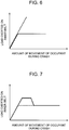
- the load characteristics of the FL mechanism 54 i.e., the relationship between the amount of movement of the occupant during a crash and a load exerted on the inner belt 50 (the load on the inner belt) is represented by the solid line in FIG. 6 .
- the dashed line in FIG. 6 represents the relationship in a case where the inner belt 50 does not include an FL mechanism.
- the load exerted on the inner belt in an early stage of a crash increases as the amount of movement of the occupant increases.
- an upper limit for example, about 5.5 kN
- the load on the inner belt does not increase further and remains substantially constant even when the amount of movement of the occupant increases.
- a time point at which the load on the inner belt reaches about 5.5 kN is a time point at which the FL mechanism 54 starts an action.
- the FL mechanism 54 of this embodiment when a load acting in the direction of pulling out the buckle 52 (the upward direction in FIG. 2A and FIG. 2B ) reaches about 5.5 kN, the deformable tube 62 starts to be deformed by the squeeze member 66. Thereafter, the buckle 52 is pulled out while the load remains substantially constant (at about 5.5 kN).
- the three-point seatbelt device S of this embodiment is a three-point seatbelt device in which the webbing 20 functions as the shoulder belt 20S and the lap belt 20L as the tongue 40 mounted on the webbing 20 is coupled to the buckle 52.
- the retractor 32 is provided at the end portion of the webbing 20 on the side of the shoulder belt 20S.
- the retractor 32 includes the PT mechanism and the FL mechanism (shoulder-side FL mechanism).
- the PT mechanism is activated during a crash, the webbing 20 is pulled in and any slack in the webbing 20 can be removed.
- the shoulder-side FL mechanism is activated, an excessive load exerted on the chest of the occupant restrained by the shoulder belt 20S can be reduced.
- the inner belt 50 including the buckle 52 also includes the FL mechanism 54 (buckle-side FL mechanism).
- the buckle-side FL mechanism 54 is activated, an excessive load exerted on the waist or the chest of the occupant can be reduced.
- the inner belt 50 of the three-point seatbelt device S can be manufactured in a compact size. Moreover, electrical control such as ignition to activate the PT mechanism is not required, which can eliminate the need for an ECU etc. to keep costs down.
- the initial load of the buckle-side FL mechanism 54 is set to be larger than the initial load of the shoulder-side FL mechanism. This setting allows the shoulder-side FL mechanism to be effectively activated compared with if the initial load of the buckle-side FL mechanism is set to be about equal to or smaller than the initial load of the shoulder-side FL mechanism. As a result, both the shoulder-side FL mechanism and the buckle-side FL mechanism 54 can be effectively activated to appropriately reduce the load exerted on the chest of the occupant.
- both the shoulder-side FL mechanism and the buckle-side FL mechanism 54 can be effectively activated to appropriately protect the occupant.
- the initial load of the buckle-side FL mechanism is set to be within a range of preferably 1.3 to 2.2 times, and more preferably 1.5 to 2.0 times, the initial load of the shoulder-side FL mechanism.
- the initial load of the buckle-side FL mechanism 54 thus set to be within an appropriate range with respect to the initial load of the shoulder-side FL mechanism, both the shoulder-side FL mechanism and the buckle-side FL mechanism 54 can be effectively activated.
- the buckle-side FL mechanism 54 is disposed between the buckle 52 and the anchorage position of the inner belt 50 (the shaft insertion hole 60A of the anchor 60).
- the buckle-side FL mechanism 54 is so compact that it can be appropriately applied even to a structure in which a center console is provided on a lateral side of the seat (vehicle seat 10) to which the three-point seatbelt device S is applied.
- the configuration of an inner belt 150 is different from the configuration of the inner belt 50 of the first embodiment.
- FIG. 4A and FIG. 4B show the inner belt 150 of the second embodiment.
- An FL mechanism 154 of the inner belt 150 of the second embodiment includes an anchor bracket 70 as a "deformable plate.”
- the anchor bracket 70 is made of metal and has a plate shape.
- a shaft insertion hole 70A is formed at a lower end of the anchor bracket 70.
- a shaft (not shown) is passed through the shaft insertion hole 70A, and the anchor bracket 70 is coupled to a vehicle body-side member so as to be rotatable around the shaft extending substantially in the seat width direction.
- a long hole 72 in which a squeeze pin 76 to be described later is fitted and of which a longitudinal direction is oriented in the up-down direction is formed in a region of the anchor bracket 70 above the shaft insertion hole 70A.
- the specific configuration of the long hole 72 will be described later.
- the FL mechanism 154 includes a buckle bracket 74 as a "tubular member" that is coupled to the buckle 52.
- the buckle bracket 74 has a tubular shape with a rectangular cross-section. A portion of the anchor bracket 70 is disposed inside the buckle bracket 74.
- a pin support hole 74A is formed in the buckle bracket 74.
- the pin support hole 74A extends through a pair of opposite side walls 74S of the buckle bracket 74.
- the squeeze pin 76 is passed through the pin support hole 74A, and both side portions of the squeeze pin 76 in an axial direction thereof are respectively supported on the side walls 74S of the buckle bracket 74.
- An intermediate portion of the squeeze pin 76 in the axial direction is fitted in a portion of the long hole 72 of the anchor bracket 70.
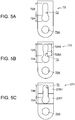
- FIG. 5A shows the anchor bracket 70 as a single component.
- the long hole 72 includes a fitting part 72A in which the squeeze pin 76 is fitted, and a deformable part 72B.
- the fitting part 72A is formed in a size corresponding to the size of the intermediate portion of the squeeze pin 76 in the axial direction.
- the deformable part 72B is formed so as to have a width dimension (in the right-left direction in FIG. 5A ) smaller than the diameter of the intermediate portion of the squeeze pin 76 in the axial direction.
- the squeeze pin 76 is normally fitted in the fitting part 72A of the long hole 72 so as not to move.
- the PT mechanism of the retractor 32 is activated, so that the webbing 20 is pulled in from the shoulder side and any slack in the webbing 20 is removed.
- a high tension is applied to the shoulder belt 20S and the lap belt 20L restraining this occupant.
- the buckle 52 is subjected to a load combining a load from the shoulder belt 20S and a load from the lap belt 20L, i.e., a large load acting in the direction of separating the buckle 52 from the anchor bracket 70 (see the arrow F in FIG.
- the load characteristics of the FL mechanism (the relationship between the amount of movement of the occupant and the load exerted on the inner belt during a crash) may be changed to the load characteristics as shown in FIG. 7 .
- the load exerted on the inner belt increases as the amount of movement of the occupant increases in an early stage of a crash.
- the load exerted on the inner belt stops increasing.
- the time point at which the load exerted on the inner belt reaches about 7 kN is a time point at which the FL mechanism 54 starts an action.
- the load exerted on the inner belt decreases to about 5.5 kN, for example. Thereafter, the load remains at about 5.5 kN even when the amount of movement of the occupant increases.
- the initial load is set to be large (about 7 kN), and the load thereafter in the latter half of the action is set to be small (about 5.5 kN).
- the load of the buckle-side FL mechanism is set to become smaller in the latter half of the action thereof than in an early stage of the action.
- the load of the buckle-side FL mechanism 54 decreases (to about 5.5 kN) to appropriately reduce the load exerted on the chest of the occupant.
- the FL mechanism having such load characteristics can be realized by changing the structure of the deformable tube 62 of the FL mechanism 54 of the first embodiment to the structures shown in FIG. 3A and FIG. 3B , or by changing the structure of the anchor bracket 70 of the FL mechanism 154 of the second embodiment to the structures shown in FIG. 5B and FIG. 5C .
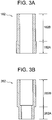
- FIG. 3A shows a deformable tube 162 of an FL mechanism according to Modified Example 1 of the first embodiment.
- the plate thickness of the deformable tube 162 changes at the border between an inlet part 162A on the lower side and a general part 162B which is a part of the deformable tube 162 other than the inlet part 162A.
- the deformable tube 162 has the inlet part 162A on the lower side with a large plate thickness (thick part) and the general part 162B with a comparatively small plate thickness (thin part).
- the internal shapes of the inlet part 162A and the general part 162B are the same.
- the external shape of the inlet part 162A is larger than the external shape of the general part 162B.
- the length of the inlet part 162A in an axial direction of the deformable tube 162 is smaller than the length of the general part 162B in the axial direction.
- FIG. 3B shows a deformable tube 262 of an FL mechanism according to Modified Example 2 of the first embodiment.
- the deformable tube 262 of Modified Example 2 is formed so as to have a constant plate thickness along the entire length in an axial direction thereof.
- the cross-sectional shape of the deformable tube 262 of Modified Example 2 changes at the border between an inlet part 262A and a general part 262B.
- the inlet part 262A of the deformable tube 262 is formed so as to have a smaller cross-sectional shape (smaller inside diameter and outside diameter) than the general part 262B.
- FIG. 5B shows an anchor bracket 170 of an FL mechanism according to Modified Example 3 of the second embodiment.
- the shape of the deformable part 72B of the long hole 72 is different from the shape of the deformable part 72B of the second embodiment.
- the deformable part 72B of the long hole 72 includes a narrow portion 72BA and a wide portion 72BB.
- the width dimensions of the narrow portion 72BA and the wide portion 72BB are both set to be smaller than the diameter of the intermediate portion of the squeeze pin 76 in the axial direction.
- the width dimension of the narrow portion 72BA is set to be smaller than that of the wide portion 72BB.
- the narrow portion 72BA is formed at a portion of the deformable part 72B adjacent to the fitting part 72A, and the wide portion 72BB is formed at a portion (general portion) of the deformable part 72B other than the narrow portion 72BA.
- the width dimension of the portion (narrow portion 72BA) of the deformable part 72B adjacent to the fitting part 72A is smaller than the width dimension of a general portion (wide portion 72BB) which is a portion of the deformable part 72B other than the portion adjacent to the fitting part 72A.
- a larger load is required to deform the narrow portion 72BA.
- the load required to deform the wide portion 72BB is smaller than the load required to deform the narrow portion 72BA.
- FIG. 5C shows an anchor bracket 270 of an FL mechanism according to Modified Example 4 of the second embodiment.
- the shape of the long hole 72 is the same as the shape of the long hole 72 of the second embodiment (see FIG. 5A ).
- the plate thickness of the anchor bracket 270 changes at a portion of a part where the long hole 72 is formed.
- the anchor bracket 270 includes a main plate 270H having the same configuration as the anchor bracket 70 of the second embodiment, and an additional plate 270T that is laid on an intermediate portion of the main plate 270H in a longitudinal direction thereof.
- the long hole 72 is formed so as to extend through both the main plate 270H and the additional plate 270T.
- the portion of the long hole 72 at which the plate thickness is increased by the additional plate 270T corresponds to the fitting part 72A of the long hole 72 and a portion of the deformable part 72B (a portion thereof adjacent to the fitting part 72A).
- the plate thickness of the anchor bracket 270 at the portion of the deformable part 72B adjacent to the fitting part 72A, i.e., the portion that is deformed in an early stage of the action of the FL mechanism, is larger than the plate thickness of the anchor bracket 270 at a general portion (the portion of the deformable part 72B not corresponding to the additional plate 270T).
- the load characteristics of the FL mechanism can be set such that the initial load is larger and the load in the latter half of the action is smaller.
- the present invention is not limited to this example.
- the three-point seatbelt device of the present invention may also be applied to a front passenger's seat or a rear seat, or to a vehicle seat that is disposed at the center in the vehicle width direction.
- the retractor 32 shoulder-side reeler
- the shoulder-side reeler may instead be provided inside a vehicle seat.
- the example has been described in which the end portion of the webbing 20 on the other side in the longitudinal direction (the side of the lap belt 20L) is engaged on the anchor member 36 fixed at the lower end of the B-pillar 16.
- the present invention is not limited to this example.
- the end portion of the webbing 20 on the lap outer side may instead be fixed to the vehicle seat.
- the end portion may be connected to a retractor (lap-side reeler) with a PT mechanism and be reeled up during a crash etc.
- the present invention is not limited to this example.
- the three-point seatbelt device of the present invention may instead be a separate three-point seatbelt device in which a lap belt and a shoulder belt are formed by separate webbings.
Abstract
Description
- The present invention relates to a three-point seatbelt device.
- In the three-point seatbelt device disclosed in Japanese Patent Application Publication No.
11-129864 JP 11-129864 A - In the three-point seatbelt device disclosed in Japanese Patent Application Publication No.
2016-97869 JP 2016-97869 A - The inner belt including the PT mechanism of
JP 11-129864 A - The technique of
JP 2016-97869 A JP 2016-97869 A - The present invention provides a compact and inexpensive three-point seatbelt device that can appropriately reduce a load exerted on the chest of an occupant during a crash.
- A three-point seatbelt device according to an aspect of the invention includes: a webbing configured to function as a shoulder belt and a lap belt; a shoulder-side reeler that includes a pre-tensioner mechanism and a shoulder-side force limiter mechanism, and is configured to reel up an end portion of the webbing on a shoulder belt side so as to allow the webbing to be pulled out; a tongue mounted on the webbing; and an inner belt including a buckle to which the tongue is coupled, the inner belt including, of a pre-tensioner mechanism and a buckle-side force limiter mechanism, only the buckle-side force limiter mechanism. An initial load of the buckle-side force limiter mechanism is set to be larger than an initial load of the shoulder-side force limiter mechanism.
- In this aspect of the three-point seatbelt device, the webbing functions as the shoulder belt and the lap belt as the tongue mounted on the webbing is coupled to the buckle. The shoulder-side reeler is provided at the shoulder belt-side end portion of the webbing. The shoulder-side reeler includes the PT mechanism and the FL mechanism (shoulder-side FL mechanism). Thus, as the PT mechanism is activated during a crash, the webbing is pulled in from the shoulder side, so that any slack in the webbing can be removed. Moreover, as the shoulder-side FL mechanism is activated, an excessive load exerted on the chest of the occupant restrained by the shoulder belt can be reduced.
- The inner belt including the buckle also includes the FL mechanism (buckle-side FL mechanism). Thus, as the buckle-side FL mechanism is activated, an excessive load exerted on the waist or the chest of the occupant can be reduced.
- Here, including no PT mechanism, the inner belt of the three-point seatbelt device can be manufactured in a compact size. Moreover, electrical control such as ignition to activate the PT mechanism is not required, which can eliminate the need for an ECU etc. to keep costs down.
- The initial load of the buckle-side FL mechanism is set to be larger than the initial load of the shoulder-side FL mechanism. This setting allows the shoulder-side FL mechanism to be effectively activated compared with if the initial load of the buckle-side FL mechanism is set to be about equal to or smaller than the initial load of the shoulder-side FL mechanism. As a result, both the shoulder-side FL mechanism and the buckle-side FL mechanism can be effectively activated to appropriately reduce the load exerted on the chest of the occupant. In particular, even during a crash such as an oblique crash in which the occupant moves toward an obliquely front side of the reeler, both the shoulder-side FL mechanism and the buckle-side FL mechanism can be effectively activated to appropriately protect the occupant.
- In the above aspect, the initial load of the buckle-side force limiter mechanism may be set to be within a range of 1.3 to 2.2 times the initial load of the shoulder-side force limiter mechanism.
- In this configuration, the initial load of the buckle-side FL mechanism is set to be within a range of 1.3 to 2.2 times the initial load of the shoulder-side FL mechanism. With the initial load of the buckle-side FL mechanism thus set to be within an appropriate range with respect to the initial load of the shoulder-side FL mechanism, both the shoulder-side FL mechanism and the buckle-side FL mechanism can be effectively activated.
- In the above aspect, a load of the buckle-side force limiter mechanism may be set to become smaller in a latter half of an action of the buckle-side force limiter mechanism than in an early stage of the action.
- In this configuration, the load of the buckle-side FL mechanism is set to become smaller in a latter half of an action thereof than in an early stage of the action. Thus, in an early stage of a crash when a load exerted on the shoulder belt starts to increase, the load (initial load) of the buckle-side FL mechanism becomes large, so that the chest of the occupant is securely restrained in the early stage of the crash. Then, in the latter half of the crash when the load exerted by the shoulder belt on the chest of the occupant becomes large as the occupant moves forward, the load of the buckle-side FL mechanism decreases so as to appropriately reduce the load exerted on the chest of the occupant.
- In the above aspect, a load of the buckle-side force limiter mechanism may be set to become smaller in a latter half of an action of the buckle-side force limiter mechanism than in an early stage of the action.
- In this configuration, the buckle-side FL mechanism is disposed between the buckle and the anchorage position of the inner belt. Thus, the buckle-side FL mechanism is so compact that it can be appropriately applied even to a structure in which a center console is provided on a lateral side of a seat to which the three-point seatbelt device is applied.
- In the above aspect, the buckle-side force limiter mechanism may include: a case; a deformable tube disposed inside the case; a wire coupled to the buckle, and extending into the case and passing through the deformable tube; and a squeeze member coupled to the wire at a lower end of the wire. The buckle-side force limiter mechanism may be configured such that, as the buckle is pulled by the tongue, the squeeze member moves upward while deforming the deformable tube and causes the buckle to be pulled out, and a lower part of the deformable tube may have a larger plate thickness than a plate thickness of the remaining part of the deformable tube or has a smaller inside diameter than an inside diameter of the remaining part of the deformable tube.
- In this configuration, the buckle-side FL mechanism can have a simple configuration and yet only the initial load thereof can be set to be large.
- In the above aspect, the buckle-side force limiter mechanism may include: a deformable plate in which a long hole is formed; a tubular member coupled to the buckle; and a squeeze pin supported at both ends on the tubular member. The long hole may include a fitting part in which the squeeze pin is fitted and a deformable part having a smaller width than the fitting part, the buckle-side force limiter mechanism may be configured such that, as the buckle is pulled by the tongue, the squeeze pin moves in a longitudinal direction of the long hole while deforming the deformable part and causes the buckle to be pulled out, and a width of a portion of the deformable part adjacent to the fitting part may be smaller than a width of the remaining portion of the deformable part, or a plate thickness of the deformable plate at the portion of the deformable part adjacent to the fitting part is larger than a plate thickness of the deformable plate at the remaining portion of the deformable part.
- In this configuration, the buckle-side FL mechanism can have a simple configuration and yet only the initial load thereof can be set to be large.
- In the above aspect, the buckle-side force limiter mechanism may include: a deformable plate in which a long hole is formed; a tubular member coupled to the buckle; and a squeeze pin supported at both ends on the tubular member. The long hole may include a fitting part in which the squeeze pin is fitted and a deformable part having a smaller width than the fitting part, the buckle-side force limiter mechanism may be configured such that, as the buckle is pulled by the tongue, the squeeze pin moves in a longitudinal direction of the long hole while deforming the deformable part and causes the buckle to be pulled out, and the deformable plate may include a main plate and an additional plate laid on a portion of the main plate such that a plate thickness of the deformable plate at a portion of the deformable part adjacent to the fitting part is larger than a plate thickness of the deformable plate at the remaining portion of the deformable part.
- Thus, a simple configuration can be realized in which the initial load of the FL mechanism is set to be large by forming the deformable plate with a partially increased plate thickness.
- Features, advantages, and technical and industrial significance of exemplary embodiments of the invention will be described below with reference to the accompanying drawings, in which like numerals denote like elements, and wherein:
-
FIG. 1 is a side view of a three-point seatbelt device of a first embodiment as seen from a lateral side of a seat; -
FIG. 2A is a partially sectional view showing an inner belt in a state where an FL mechanism of the first embodiment is not in action; -
FIG. 2B is a partially sectional view showing the inner belt in a state where the FL mechanism of the first embodiment is in action; -
FIG. 3A is a sectional view showing a deformable tube of an inner belt according to Modified Example 1 of the first embodiment; -
FIG. 3B is a sectional view showing a deformable tube of an inner belt according to Modified Example 2 of the first embodiment; -
FIG. 4A is a side view of an inner belt of a second embodiment as seen from the lateral side of the seat; -
FIG. 4B is a sectional view taken along line IVB-IVB inFIG. 4A ; -
FIG. 5A is a view showing an anchor bracket of the inner belt of the second embodiment; -
FIG. 5B is a view showing an anchor bracket according to Modified Example 3 of the second embodiment; -
FIG. 5C is a view showing an anchor bracket according to Modified Example 4 of the second embodiment; -
FIG. 6 is a graph showing the load characteristics of the FL mechanism; and -
FIG. 7 is a graph showing a modified example of the load characteristics of the FL mechanism. - A three-point seatbelt device S according to a first embodiment will be described below using
FIG. 1 to FIG. 6 . - The arrows FR, UP, W1, and W2 in the drawings respectively indicate a front side in a seat front-rear direction, an upper side in a seat up-down direction, one side in a seat width direction (buckle side), and the other side in the seat width direction (retractor side). Unless otherwise specified, the words front and rear sides, upper and lower sides, and one and the other sides in the width direction used in the following description respectively mean front and rear sides in the seat front-rear direction, upper and lower sides in the seat up-down direction, and one and the other sides in the seat width direction.
- As shown in
FIG. 1 , the three-point seatbelt device S according to this embodiment is applied to avehicle seat 10 that is a right-side seat in a first row (the driver's seat in a right-hand drive vehicle). Thus, in this embodiment, a vehicle front side, a vehicle upper side, an inner side in a vehicle width direction, and an outer side in the vehicle width direction respectively coincide with the seat front side, the seat upper side, the one side in the seat width direction, and the other side in the seat width direction. - The three-point seatbelt device S includes a
webbing 20 that restrains an occupant. Thewebbing 20 is made of a material such as chemical fiber and formed as a flexible elongated belt. An end portion of thewebbing 20 on one side in a longitudinal direction thereof (on the side of ashoulder belt 20S) is engaged on a spool (not shown) of aretractor 32 serving as a "shoulder-side reeler" provided at a lower end of a B-pillar 16. An intermediate portion of thewebbing 20 in the longitudinal direction is passed through a shoulder anchor 34 (a slip guide or a slip joint), provided at an upper part of the B-pillar 16, so as to be folded back. An end portion of thewebbing 20 on the other side in the longitudinal direction thereof (on the side of alap belt 20L) is engaged on ananchor member 36 fixed at the lower end of the B-pillar 16. - A
tongue 40 is mounted on a portion of thewebbing 20 between theshoulder anchor 34 and theanchor member 36 so as to be movable in the longitudinal direction of thewebbing 20. - An
inner belt 50 is provided on one side of thevehicle seat 10 in the seat width direction (the inner side in the vehicle width direction). Theinner belt 50 includes abuckle 52. When thetongue 40 is coupled to thebuckle 52, the occupant seated in thevehicle seat 10 is fastened with the seatbelt (this state will be hereinafter referred to as a fastened state). In the fastened state, a portion of thewebbing 20 between thetongue 40 and theshoulder anchor 34 functions as theshoulder belt 20S that restrains the chest and the shoulder of the occupant, while a portion of thewebbing 20 between thetongue 40 and theanchor member 36 functions as thelap belt 20L that restrains the waist of the occupant. - The
retractor 32 is a reeler that reels up thewebbing 20 on the spool and houses thewebbing 20 so as to allow thewebbing 20 to be pulled out. Theretractor 32 has a locking mechanism that locks the spool so as not to rotate and restricts pulling out of thewebbing 20, when it is detected that an acceleration rate of the vehicle is not lower than a predetermined value or that a pull-out acceleration rate of thewebbing 20 is not lower than a predetermined value. - The
retractor 32 has a PT mechanism (not shown). The PT mechanism may be a publicly known one, and for example, is of a pyrotechnic type. When a frontal crash is detected, an explosive is ignited, which causes the spool to rotate and forcibly reel up thewebbing 20. Theretractor 32 further has a pre-crash seatbelt mechanism. When a frontal crash or a lateral crash is predicted, the pre-crash seatbelt mechanism rotates the spool by the driving force of a motor to forcibly reel up thewebbing 20. - The
retractor 32 further has an FL mechanism (not shown; hereinafter referred to as a shoulder-side FL mechanism). The shoulder-side FL mechanism may be a publicly known one. In this embodiment, for example, the initial load of the shoulder-side FL mechanism is set to about 4 kN. The initial load of the FL mechanism means a load (a load in a direction in which the webbing is pulled out) required for the FL mechanism to start an action from an inactive state. -
FIG. 2A shows theinner belt 50 with a longitudinal direction thereof oriented in the up-down direction. Theinner belt 50 is coupled to thetongue 40 at thebuckle 52 on one side in the longitudinal direction (upper side), and is rotatably coupled to a vehicle body-side member such as a vehicle body or thevehicle seat 10 on the other end side (lower side). Theinner belt 50 includes anFL mechanism 54 as a "buckle-side FL mechanism." As can be understood from the other part of the description of this embodiment, in this specification, a member that includes the buckle and is coupled to a vehicle body-side member is referred to as an inner belt. Therefore, a member that does not include an elongated belt-shaped member like a webbing as in this embodiment also corresponds to the inner belt. - The
FL mechanism 54 includes acase 56. Thecase 56 includes ahousing part 58 in which adeformable tube 62 and asqueeze member 66 to be described later are disposed, and ananchor 60 coupled to the vehicle body-side member. Theanchor 60 has ashaft insertion hole 60A. Theinner belt 50 is rotatably coupled to the vehicle body-side member by using theshaft insertion hole 60A. - The
housing part 58 is formed integrally with theanchor 60. Thehousing part 58 is formed so as to protrude toward the one side in the seat width direction (the inner side in the vehicle width direction) relative to the flat plate-shapedanchor 60. In other words, thehousing part 58 is located on the outer side in the seat width direction relative to an imaginary plane defined by the plate-shapedanchor 60. Thehousing part 58 has a substantially rectangular parallelepiped shape. - The
FL mechanism 54 includes thedeformable tube 62. Thedeformable tube 62 is provided inside thecase 56. Thedeformable tube 62 extends in the longitudinal direction of theinner belt 50 and has a tube shape with a quadrangular cross-section, and is formed so as to have a constant plate thickness from an upper end to a lower end. The upper end of thedeformable tube 62 is joined to anupper wall 58T of thecase 56, and the lower end of thedeformable tube 62 is disposed with a clearance to alower wall 58B of thecase 56. - The
FL mechanism 54 includes awire 64 coupled to thebuckle 52. One end (upper end) of thewire 64 is coupled to thebuckle 52, while the other end is inserted into thecase 56 through a through-hole 58A formed in theupper wall 58T of thecase 56. The through-hole 58A of theupper wall 58T communicates with an inside of thedeformable tube 62, and thewire 64 passes through the inside of thedeformable tube 62. Thesqueeze member 66 is mounted at the other end (lower end) of thewire 64. - Specifically, the
squeeze member 66 has aninsertion hole 66A for thewire 64 to pass through. Thewire 64 is passed through theinsertion hole 66A of thesqueeze member 66, and an engagingmember 68 is fixed at the other end (lower end) of thewire 64. Thus, thesqueeze member 66 is prevented from coming off from the other end side of thewire 64. - The
insertion hole 66A of thesqueeze member 66 extends through thesqueeze member 66 in the up-down direction. The cross-section of thesqueeze member 66 orthogonal to the up-down direction has a quadrangular shape similar to the cross-sectional shape of thedeformable tube 62. Thesqueeze member 66 is shaped so as to expand gradually from an upper end toward a lower end. Thus, aside surface 66S of thesqueeze member 66 is a flat surface inclined in a direction away from a central axis of the squeeze member (in this embodiment, from a portion thereof where thewire 64 is passed) while extending from the upper end toward the lower end of thesqueeze member 66. - A portion of the
squeeze member 66 on the upper side is disposed inside thedeformable tube 62. On the other hand, a portion of thesqueeze member 66 on the lower side is disposed outside the deformable tube 62 (on the lower side of the deformable tube 62). Theside surface 66S of thesqueeze member 66 is in contact with the lower end of thedeformable tube 62. Specifically, the entire circumference of thedeformable tube 62 at the lower end is in contact with theinclined side surface 66S of thesqueeze member 66. - Next, an action of the
FL mechanism 54 will be described. - For example, when a form of crash such as a frontal crash in which the occupant moves toward the seat front side occurs, the
buckle 52 is subjected to a large load acting in the direction of separating thebuckle 52 from thecase 56. This load is transmitted to thesqueeze member 66 through thewire 64 coupled to thebuckle 52, causing thesqueeze member 66 to move upward while deforming the deformable tube 62 (FIG. 2B ). Thus, energy is absorbed by deformation of thedeformable tube 62, and thebuckle 52 is pulled out upward. - Specifically, the
deformable tube 62 deforms along theinclined side surface 66S of thesqueeze member 66. As thesqueeze member 66 comes in contact with theupper wall 58T of thecase 56, the amount of thebuckle 52 pulled out is limited. The dimension of the cross-section of thesqueeze member 66 at the lower end is set such that the deformeddeformable tube 62 comes in contact with or closer to thecase 56 from the inner side. - The load characteristics of the
FL mechanism 54, i.e., the relationship between the amount of movement of the occupant during a crash and a load exerted on the inner belt 50 (the load on the inner belt) is represented by the solid line inFIG. 6 . The dashed line inFIG. 6 represents the relationship in a case where theinner belt 50 does not include an FL mechanism. - As shown in
FIG. 6 , the load exerted on the inner belt in an early stage of a crash increases as the amount of movement of the occupant increases. However, after hitting an upper limit, for example, about 5.5 kN, the load on the inner belt does not increase further and remains substantially constant even when the amount of movement of the occupant increases. A time point at which the load on the inner belt reaches about 5.5 kN is a time point at which theFL mechanism 54 starts an action. Thus, in theFL mechanism 54 of this embodiment, when a load acting in the direction of pulling out the buckle 52 (the upward direction inFIG. 2A and FIG. 2B ) reaches about 5.5 kN, thedeformable tube 62 starts to be deformed by thesqueeze member 66. Thereafter, thebuckle 52 is pulled out while the load remains substantially constant (at about 5.5 kN). - Next, operational effects of this embodiment will be described.
- The three-point seatbelt device S of this embodiment is a three-point seatbelt device in which the
webbing 20 functions as theshoulder belt 20S and thelap belt 20L as thetongue 40 mounted on thewebbing 20 is coupled to thebuckle 52. Theretractor 32 is provided at the end portion of thewebbing 20 on the side of theshoulder belt 20S. Theretractor 32 includes the PT mechanism and the FL mechanism (shoulder-side FL mechanism). Thus, as the PT mechanism is activated during a crash, thewebbing 20 is pulled in and any slack in thewebbing 20 can be removed. Moreover, as the shoulder-side FL mechanism is activated, an excessive load exerted on the chest of the occupant restrained by theshoulder belt 20S can be reduced. Theinner belt 50 including thebuckle 52 also includes the FL mechanism 54 (buckle-side FL mechanism). Thus, as the buckle-side FL mechanism 54 is activated, an excessive load exerted on the waist or the chest of the occupant can be reduced. - Here, including no PT mechanism, the
inner belt 50 of the three-point seatbelt device S can be manufactured in a compact size. Moreover, electrical control such as ignition to activate the PT mechanism is not required, which can eliminate the need for an ECU etc. to keep costs down. - The initial load of the buckle-
side FL mechanism 54 is set to be larger than the initial load of the shoulder-side FL mechanism. This setting allows the shoulder-side FL mechanism to be effectively activated compared with if the initial load of the buckle-side FL mechanism is set to be about equal to or smaller than the initial load of the shoulder-side FL mechanism. As a result, both the shoulder-side FL mechanism and the buckle-side FL mechanism 54 can be effectively activated to appropriately reduce the load exerted on the chest of the occupant. In particular, even during a crash such as an oblique crash in which the occupant moves toward an obliquely front side of the reeler (in this embodiment, provided on the outer side in the vehicle width direction), both the shoulder-side FL mechanism and the buckle-side FL mechanism 54 can be effectively activated to appropriately protect the occupant. - The initial load of the buckle-side FL mechanism is set to be within a range of preferably 1.3 to 2.2 times, and more preferably 1.5 to 2.0 times, the initial load of the shoulder-side FL mechanism. With the initial load of the buckle-
side FL mechanism 54 thus set to be within an appropriate range with respect to the initial load of the shoulder-side FL mechanism, both the shoulder-side FL mechanism and the buckle-side FL mechanism 54 can be effectively activated. - In this embodiment, the buckle-
side FL mechanism 54 is disposed between thebuckle 52 and the anchorage position of the inner belt 50 (theshaft insertion hole 60A of the anchor 60). Thus, the buckle-side FL mechanism 54 is so compact that it can be appropriately applied even to a structure in which a center console is provided on a lateral side of the seat (vehicle seat 10) to which the three-point seatbelt device S is applied. - Next, a three-point seatbelt device according to a second embodiment will be described. In the second embodiment, the configuration of an
inner belt 150 is different from the configuration of theinner belt 50 of the first embodiment. -
FIG. 4A and FIG. 4B show theinner belt 150 of the second embodiment. AnFL mechanism 154 of theinner belt 150 of the second embodiment includes ananchor bracket 70 as a "deformable plate." Theanchor bracket 70 is made of metal and has a plate shape. Ashaft insertion hole 70A is formed at a lower end of theanchor bracket 70. A shaft (not shown) is passed through theshaft insertion hole 70A, and theanchor bracket 70 is coupled to a vehicle body-side member so as to be rotatable around the shaft extending substantially in the seat width direction. - A
long hole 72 in which asqueeze pin 76 to be described later is fitted and of which a longitudinal direction is oriented in the up-down direction is formed in a region of theanchor bracket 70 above theshaft insertion hole 70A. The specific configuration of thelong hole 72 will be described later. - The
FL mechanism 154 includes abuckle bracket 74 as a "tubular member" that is coupled to thebuckle 52. Thebuckle bracket 74 has a tubular shape with a rectangular cross-section. A portion of theanchor bracket 70 is disposed inside thebuckle bracket 74. - A
pin support hole 74A is formed in thebuckle bracket 74. Thepin support hole 74A extends through a pair ofopposite side walls 74S of thebuckle bracket 74. Thesqueeze pin 76 is passed through thepin support hole 74A, and both side portions of thesqueeze pin 76 in an axial direction thereof are respectively supported on theside walls 74S of thebuckle bracket 74. An intermediate portion of thesqueeze pin 76 in the axial direction is fitted in a portion of thelong hole 72 of theanchor bracket 70. -
FIG. 5A shows theanchor bracket 70 as a single component. Thelong hole 72 includes afitting part 72A in which thesqueeze pin 76 is fitted, and adeformable part 72B. Thefitting part 72A is formed in a size corresponding to the size of the intermediate portion of thesqueeze pin 76 in the axial direction. On the other hand, thedeformable part 72B is formed so as to have a width dimension (in the right-left direction inFIG. 5A ) smaller than the diameter of the intermediate portion of thesqueeze pin 76 in the axial direction. Thus, thesqueeze pin 76 is normally fitted in thefitting part 72A of thelong hole 72 so as not to move. - Next, an action of the
FL mechanism 154 will be described. - For example, when a form of crash such as a frontal crash in which the occupant moves toward the seat front side occurs, first, the PT mechanism of the
retractor 32 is activated, so that thewebbing 20 is pulled in from the shoulder side and any slack in thewebbing 20 is removed. Next, as the occupant tries to move toward the seat front side by inertia, a high tension is applied to theshoulder belt 20S and thelap belt 20L restraining this occupant. Then, thebuckle 52 is subjected to a load combining a load from theshoulder belt 20S and a load from thelap belt 20L, i.e., a large load acting in the direction of separating thebuckle 52 from the anchor bracket 70 (see the arrow F inFIG. 4A ). This load is transmitted to thesqueeze pin 76 through thebuckle bracket 74 coupled to thebuckle 52, causing thesqueeze pin 76 to move upward while deforming thedeformable part 72B of thelong hole 72. Thus, energy is absorbed by deformation of the long hole 72 (anchor bracket 70), and thebuckle 52 is pulled out upward. TheFL mechanism 154 can also realize the load characteristics shown inFIG. 6 . - The load characteristics of the FL mechanism (the relationship between the amount of movement of the occupant and the load exerted on the inner belt during a crash) may be changed to the load characteristics as shown in
FIG. 7 . - As shown in
FIG. 7 , in the modified example of the load characteristics, the load exerted on the inner belt increases as the amount of movement of the occupant increases in an early stage of a crash. At a time point when the load exerted on the inner belt reaches about 7 kN, for example, the load exerted on the inner belt stops increasing. The time point at which the load exerted on the inner belt reaches about 7 kN is a time point at which theFL mechanism 54 starts an action. When the amount of forward movement of the occupant further increases, the load exerted on the inner belt decreases to about 5.5 kN, for example. Thereafter, the load remains at about 5.5 kN even when the amount of movement of the occupant increases. - As has been described above, in the modified example of the load characteristics, the initial load is set to be large (about 7 kN), and the load thereafter in the latter half of the action is set to be small (about 5.5 kN). Thus, the load of the buckle-side FL mechanism is set to become smaller in the latter half of the action thereof than in an early stage of the action. As a result, in an early stage of a crash when the load exerted on the
shoulder belt 20S starts to increase, the load of the buckle-side FL mechanism 54 becomes large (initial load: about 7 kN), so that the chest of the occupant is securely restrained in the early stage of the crash. Then, in the latter half of the crash when the load exerted by theshoulder belt 20S on the chest of the occupant becomes large as the occupant moves, the load of the buckle-side FL mechanism 54 decreases (to about 5.5 kN) to appropriately reduce the load exerted on the chest of the occupant. - For example, the FL mechanism having such load characteristics can be realized by changing the structure of the
deformable tube 62 of theFL mechanism 54 of the first embodiment to the structures shown inFIG. 3A and FIG. 3B , or by changing the structure of theanchor bracket 70 of theFL mechanism 154 of the second embodiment to the structures shown inFIG. 5B and FIG. 5C . -
FIG. 3A shows adeformable tube 162 of an FL mechanism according to Modified Example 1 of the first embodiment. The plate thickness of thedeformable tube 162 changes at the border between aninlet part 162A on the lower side and ageneral part 162B which is a part of thedeformable tube 162 other than theinlet part 162A. Specifically, thedeformable tube 162 has theinlet part 162A on the lower side with a large plate thickness (thick part) and thegeneral part 162B with a comparatively small plate thickness (thin part). The internal shapes of theinlet part 162A and thegeneral part 162B are the same. On the other hand, the external shape of theinlet part 162A is larger than the external shape of thegeneral part 162B. The length of theinlet part 162A in an axial direction of thedeformable tube 162 is smaller than the length of thegeneral part 162B in the axial direction. -
FIG. 3B shows adeformable tube 262 of an FL mechanism according to Modified Example 2 of the first embodiment. Unlike thedeformable tube 162 of Modified Example 1, thedeformable tube 262 of Modified Example 2 is formed so as to have a constant plate thickness along the entire length in an axial direction thereof. On the other hand, the cross-sectional shape of thedeformable tube 262 of Modified Example 2 changes at the border between aninlet part 262A and ageneral part 262B. Thus, theinlet part 262A of thedeformable tube 262 is formed so as to have a smaller cross-sectional shape (smaller inside diameter and outside diameter) than thegeneral part 262B. - Also with either of the
deformable tubes FIG. 2A and FIG. 2B ) deforms theinlet parts deformable tubes general parts deformable tubes FIG. 7 can be realized. -
FIG. 5B shows ananchor bracket 170 of an FL mechanism according to Modified Example 3 of the second embodiment. In theanchor bracket 170 of Modified Example 3, the shape of thedeformable part 72B of thelong hole 72 is different from the shape of thedeformable part 72B of the second embodiment. Thedeformable part 72B of thelong hole 72 includes a narrow portion 72BA and a wide portion 72BB. The width dimensions of the narrow portion 72BA and the wide portion 72BB are both set to be smaller than the diameter of the intermediate portion of thesqueeze pin 76 in the axial direction. The width dimension of the narrow portion 72BA is set to be smaller than that of the wide portion 72BB. The narrow portion 72BA is formed at a portion of thedeformable part 72B adjacent to thefitting part 72A, and the wide portion 72BB is formed at a portion (general portion) of thedeformable part 72B other than the narrow portion 72BA. - In Modified Example 3, the width dimension of the portion (narrow portion 72BA) of the
deformable part 72B adjacent to thefitting part 72A, i.e., the portion that is deformed in an early stage of the action of the FL mechanism, is smaller than the width dimension of a general portion (wide portion 72BB) which is a portion of thedeformable part 72B other than the portion adjacent to thefitting part 72A. Thus, in the early stage of the action of the FL mechanism, a larger load is required to deform the narrow portion 72BA. On the other hand, in the latter half of the action, the load required to deform the wide portion 72BB is smaller than the load required to deform the narrow portion 72BA. Thus, the load characteristics of the FL mechanism can be set such that the initial load is larger and the load in the latter half of the action is smaller. -
FIG. 5C shows ananchor bracket 270 of an FL mechanism according to Modified Example 4 of the second embodiment. In theanchor bracket 270 of Modified Example 4, the shape of thelong hole 72 is the same as the shape of thelong hole 72 of the second embodiment (seeFIG. 5A ). On the other hand, the plate thickness of theanchor bracket 270 changes at a portion of a part where thelong hole 72 is formed. Specifically, theanchor bracket 270 includes amain plate 270H having the same configuration as theanchor bracket 70 of the second embodiment, and anadditional plate 270T that is laid on an intermediate portion of themain plate 270H in a longitudinal direction thereof. Thelong hole 72 is formed so as to extend through both themain plate 270H and theadditional plate 270T. The portion of thelong hole 72 at which the plate thickness is increased by theadditional plate 270T corresponds to thefitting part 72A of thelong hole 72 and a portion of thedeformable part 72B (a portion thereof adjacent to thefitting part 72A). - In Modified Example 4, the plate thickness of the
anchor bracket 270 at the portion of thedeformable part 72B adjacent to thefitting part 72A, i.e., the portion that is deformed in an early stage of the action of the FL mechanism, is larger than the plate thickness of theanchor bracket 270 at a general portion (the portion of thedeformable part 72B not corresponding to theadditional plate 270T). Thus, the load characteristics of the FL mechanism can be set such that the initial load is larger and the load in the latter half of the action is smaller. - In the above embodiments, the example in which the three-point seatbelt device is applied to the driver's seat has been described, but the present invention is not limited to this example. The three-point seatbelt device of the present invention may also be applied to a front passenger's seat or a rear seat, or to a vehicle seat that is disposed at the center in the vehicle width direction.
- In the above embodiments, the example in which the retractor 32 (shoulder-side reeler) is provided at the lower end of the B-
pillar 16 has been described, but the present invention is not limited to this example. The shoulder-side reeler may instead be provided inside a vehicle seat. - In the above embodiments, the example has been described in which the end portion of the
webbing 20 on the other side in the longitudinal direction (the side of thelap belt 20L) is engaged on theanchor member 36 fixed at the lower end of the B-pillar 16. However, the present invention is not limited to this example. For example, the end portion of thewebbing 20 on the lap outer side may instead be fixed to the vehicle seat. Moreover, the end portion may be connected to a retractor (lap-side reeler) with a PT mechanism and be reeled up during a crash etc. - In the above embodiments, the example in which the
tongue 40 is mounted so as to be movable in the longitudinal direction of the webbing 20 (continuous three-point seatbelt device) has been described, but the present invention is not limited to this example. The three-point seatbelt device of the present invention may instead be a separate three-point seatbelt device in which a lap belt and a shoulder belt are formed by separate webbings.
Claims (7)
- A three-point seatbelt device (S) comprising:a webbing (20) configured to function as a shoulder belt and a lap belt;a shoulder-side reeler (32) that includes a pre-tensioner mechanism and a shoulder-side force limiter mechanism, and is configured to reel up an end portion of the webbing on a shoulder belt side so as to allow the webbing to be pulled out;a tongue (40) mounted on the webbing (20); andan inner belt (50) including a buckle (52) to which the tongue (40) is coupled, the inner belt (50) including, of a pre-tensioner mechanism and a buckle-side force limiter mechanism (54), only the buckle-side force limiter mechanism (54),wherein an initial load of the buckle-side force limiter mechanism (54) is set to be larger than an initial load of the shoulder-side force limiter mechanism.
- The three-point seatbelt device (S) according to claim 1, wherein
the initial load of the buckle-side force limiter mechanism (54) is set to be within a range of 1.3 to 2.2 times the initial load of the shoulder-side force limiter mechanism. - The three-point seatbelt device (S) according to claim 1 or 2, wherein
a load of the buckle-side force limiter mechanism (54) is set to become smaller in a latter half of an action of the buckle-side force limiter mechanism (54) than in an early stage of the action. - The three-point seatbelt device (S) according to any one of claims 1 to 3, wherein the buckle-side force limiter mechanism (54) is disposed between the buckle (52) and an anchorage position at which the inner belt is fixed to a vehicle body-side member.
- The three-point seatbelt device (S) according to claim 3, wherein
the buckle-side force limiter mechanism (54) includes:a case (56);a deformable tube (62) disposed inside the case (56);a wire (64) coupled to the buckle, and extending into the case (56) and passing through the deformable tube (62); anda squeeze member (66) coupled to the wire (64) at a lower end of the wire (64),the buckle-side force limiter mechanism (54) is configured such that, as the buckle (52) is pulled by the tongue (40), the squeeze member (66) moves upward while deforming the deformable tube (62) and causes the buckle (52) to be pulled out, and
a lower part of the deformable tube (62) has a larger plate thickness than a plate thickness of the remaining part of the deformable tube (62) or has a smaller inside diameter than an inside diameter of the remaining part of the deformable tube (62). - The three-point seatbelt device according to claim 3, wherein
the buckle-side force limiter mechanism (54) includesa deformable plate (70) in which a long hole (72) is formed,a tubular member (74) coupled to the buckle (52), anda squeeze pin (76) supported at both ends on the tubular member,the long hole (72) includes a fitting part (72A) in which the squeeze pin (76) is fitted and a deformable part (72B) having a smaller width than the fitting part (72A),
the buckle-side force limiter mechanism (54) is configured such that, as the buckle (52) is pulled by the tongue (40), the squeeze pin (76) moves in a longitudinal direction of the long hole (72) while deforming the deformable part (72B) and causes the buckle (52) to be pulled out, and
a width of a portion of the deformable part (72B) adjacent to the fitting part (72A) is smaller than a width of the remaining portion of the deformable part (72B), or a plate thickness of the deformable plate (70) at the portion of the deformable part (72B) adjacent to the fitting part (72A) is larger than a plate thickness of the deformable plate (70) at the remaining portion of the deformable part (72B). - The three-point seatbelt device according to claim 3, wherein
the buckle-side force limiter mechanism (54) includesa deformable plate (70) in which a long hole (72) is formed,a tubular member (74) coupled to the buckle (52), anda squeeze pin (76) supported at both ends on the tubular member (74),the long hole (72) includes a fitting part (72A) in which the squeeze pin (76) is fitted and a deformable part (72B) having a smaller width than the fitting part (72A),
the buckle-side force limiter mechanism (54) is configured such that, as the buckle (52) is pulled by the tongue (40), the squeeze pin (76) moves in a longitudinal direction of the long hole (72) while deforming the deformable part (72B) and causes the buckle (52) to be pulled out, and
the deformable plate (70) includes a main plate (270H) and an additional plate (270T) laid on a portion of the main plate (270H) such that a plate thickness of the deformable plate (70) at a portion of the deformable part (72B) adjacent to the fitting part (72A) is larger than a plate thickness of the deformable plate (70) at the remaining portion of the deformable part (72B).
Applications Claiming Priority (1)
| Application Number | Priority Date | Filing Date | Title |
|---|---|---|---|
| JP2017170425A JP6891742B2 (en) | 2017-09-05 | 2017-09-05 | 3-point seat belt device |
Publications (2)
| Publication Number | Publication Date |
|---|---|
| EP3450262A1 true EP3450262A1 (en) | 2019-03-06 |
| EP3450262B1 EP3450262B1 (en) | 2020-04-15 |
Family
ID=63165269
Family Applications (1)
| Application Number | Title | Priority Date | Filing Date |
|---|---|---|---|
| EP18187499.1A Active EP3450262B1 (en) | 2017-09-05 | 2018-08-06 | Three-point seatbelt device |
Country Status (6)
| Country | Link |
|---|---|
| US (1) | US10703332B2 (en) |
| EP (1) | EP3450262B1 (en) |
| JP (1) | JP6891742B2 (en) |
| KR (1) | KR102146873B1 (en) |
| CN (1) | CN109421656B (en) |
| RU (1) | RU2699167C1 (en) |
Families Citing this family (7)
| Publication number | Priority date | Publication date | Assignee | Title |
|---|---|---|---|---|
| DE102017201016A1 (en) * | 2017-01-23 | 2018-07-26 | Volkswagen Aktiengesellschaft | Seat belt device for a vehicle |
| US10543807B2 (en) * | 2018-01-03 | 2020-01-28 | Ford Global Technologies, Llc | Energy absorbing restraint system |
| JP7132141B2 (en) * | 2019-02-04 | 2022-09-06 | トヨタ自動車株式会社 | Buckle device, seat mounting structure for buckle device, and seat belt device for vehicle |
| JP7136728B2 (en) | 2019-03-15 | 2022-09-13 | トヨタ自動車株式会社 | seat belt device |
| JP6933681B2 (en) * | 2019-03-22 | 2021-09-08 | オートリブ ディベロップメント エービー | Seat belt buckle device |
| KR20210064864A (en) | 2019-11-26 | 2021-06-03 | 홍도현 | 3-point standing belt mechanism |
| JP7348935B2 (en) | 2021-08-26 | 2023-09-21 | 株式会社東海理化電機製作所 | buckle device |
Citations (7)
| Publication number | Priority date | Publication date | Assignee | Title |
|---|---|---|---|---|
| DE2621983A1 (en) * | 1976-05-18 | 1977-12-01 | Zinser Maschinenbau Kg | Anchoring fitting for seat belt - has cable extending from buckle and fitted with plunger element which deforms nut |
| US4674801A (en) * | 1985-02-06 | 1987-06-23 | Allied Corporation | Energy absorber having a limited stroke |
| JPH1199908A (en) * | 1997-09-29 | 1999-04-13 | Nippon Seiko Kk | Seat belt with energy absorbing mechanism |
| JPH11129864A (en) | 1997-10-27 | 1999-05-18 | Nippon Seiko Kk | Seat belt device for vehicle |
| JP2013018460A (en) * | 2011-07-14 | 2013-01-31 | Toyota Motor Corp | Seat belt device for automobile |
| GB2522335A (en) * | 2014-12-16 | 2015-07-22 | Daimler Ag | Load limiting device for a seat belt of a vehicle |
| JP2016097869A (en) | 2014-11-25 | 2016-05-30 | トヨタ自動車株式会社 | Vehicle occupant protection device |
Family Cites Families (16)
| Publication number | Priority date | Publication date | Assignee | Title |
|---|---|---|---|---|
| JPS5028499Y1 (en) * | 1969-08-06 | 1975-08-22 | ||
| FR2133114A5 (en) * | 1971-04-08 | 1972-11-24 | Noir Rene | |
| JPS4872623U (en) * | 1971-12-17 | 1973-09-11 | ||
| US3942819A (en) * | 1972-05-12 | 1976-03-09 | Volkswagenwerk Aktiengesellschaft | Safety belt tensioning device |
| JPS57113158U (en) * | 1980-12-29 | 1982-07-13 | ||
| DE4224924A1 (en) * | 1992-07-28 | 1994-02-03 | Trw Repa Gmbh | Seat belt restraint system with belt tensioner |
| DE19511457A1 (en) * | 1995-03-29 | 1996-10-02 | Trw Repa Gmbh | Force limitation in an occupant restraint system |
| DE29608210U1 (en) * | 1996-05-06 | 1996-09-12 | Trw Repa Gmbh | Linear drive for a vehicle occupant restraint system |
| DE29718661U1 (en) * | 1997-10-21 | 1998-02-19 | Trw Repa Gmbh | Force limiter for a vehicle occupant restraint system |
| JP2002308045A (en) | 2001-04-12 | 2002-10-23 | Takata Corp | Seat belt device |
| GB2387575B (en) | 2002-04-16 | 2004-04-14 | Breed Automotive Tech | Retractor |
| JP4907249B2 (en) * | 2006-07-19 | 2012-03-28 | タカタ株式会社 | Seat belt retractor and seat belt device |
| ATE556899T1 (en) * | 2007-02-12 | 2012-05-15 | Takata Petri Ag | LOCK DEFLECTION DEVICE |
| DE112009000994T5 (en) * | 2008-04-23 | 2011-02-17 | GM Global Technology Operations, Inc., Detroit | Seatbelt retractor using an active material actuator |
| JP5510647B2 (en) * | 2010-03-30 | 2014-06-04 | マツダ株式会社 | Seat belt device and method of assembling the same |
| CN103781661A (en) * | 2011-08-29 | 2014-05-07 | 丰田自动车株式会社 | Seat structure for vehicle |
-
2017
- 2017-09-05 JP JP2017170425A patent/JP6891742B2/en active Active
-
2018
- 2018-07-30 US US16/048,878 patent/US10703332B2/en active Active
- 2018-08-03 KR KR1020180090982A patent/KR102146873B1/en active IP Right Grant
- 2018-08-06 EP EP18187499.1A patent/EP3450262B1/en active Active
- 2018-08-08 RU RU2018128973A patent/RU2699167C1/en active
- 2018-08-30 CN CN201811000728.9A patent/CN109421656B/en active Active
Patent Citations (7)
| Publication number | Priority date | Publication date | Assignee | Title |
|---|---|---|---|---|
| DE2621983A1 (en) * | 1976-05-18 | 1977-12-01 | Zinser Maschinenbau Kg | Anchoring fitting for seat belt - has cable extending from buckle and fitted with plunger element which deforms nut |
| US4674801A (en) * | 1985-02-06 | 1987-06-23 | Allied Corporation | Energy absorber having a limited stroke |
| JPH1199908A (en) * | 1997-09-29 | 1999-04-13 | Nippon Seiko Kk | Seat belt with energy absorbing mechanism |
| JPH11129864A (en) | 1997-10-27 | 1999-05-18 | Nippon Seiko Kk | Seat belt device for vehicle |
| JP2013018460A (en) * | 2011-07-14 | 2013-01-31 | Toyota Motor Corp | Seat belt device for automobile |
| JP2016097869A (en) | 2014-11-25 | 2016-05-30 | トヨタ自動車株式会社 | Vehicle occupant protection device |
| GB2522335A (en) * | 2014-12-16 | 2015-07-22 | Daimler Ag | Load limiting device for a seat belt of a vehicle |
Also Published As
| Publication number | Publication date |
|---|---|
| JP2019043435A (en) | 2019-03-22 |
| CN109421656B (en) | 2021-03-30 |
| KR102146873B1 (en) | 2020-08-21 |
| CN109421656A (en) | 2019-03-05 |
| KR20190026565A (en) | 2019-03-13 |
| EP3450262B1 (en) | 2020-04-15 |
| JP6891742B2 (en) | 2021-06-18 |
| US10703332B2 (en) | 2020-07-07 |
| BR102018067280A2 (en) | 2019-03-26 |
| US20190071053A1 (en) | 2019-03-07 |
| RU2699167C1 (en) | 2019-09-03 |
Similar Documents
| Publication | Publication Date | Title |
|---|---|---|
| EP3450262B1 (en) | Three-point seatbelt device | |
| EP3442835B1 (en) | Seatbelt pretensioning retractor assembly | |
| CN110546044B (en) | Seatbelt pretensioner retractor assembly including gas release opening | |
| CN110520336B (en) | Belt pretensioner retractor assembly including a piston safety valve member | |
| CN110520335B (en) | Seat belt pretensioner retractor assembly including pretensioner lever | |
| JP6893263B2 (en) | Retractor pretensioner assembly | |
| JP2007238030A (en) | Seat belt device | |
| JP2023032338A (en) | Buckle device | |
| KR0149093B1 (en) | Energy absorbing device of a buckle anchor | |
| KR102585755B1 (en) | Seat belt safety apparatus for vehicle | |
| BR102018067280B1 (en) | THREE POINT SEAT BELT DEVICE | |
| JP6597522B2 (en) | Vehicle seat belt device | |
| JP2021133790A (en) | Vehicle seat device including lap pretensioner | |
| JP2019001371A (en) | Seat Belt Device | |
| JP2003002162A (en) | Seat belt device | |
| JP2004230991A (en) | Seat belt device |
Legal Events
| Date | Code | Title | Description |
|---|---|---|---|
| PUAI | Public reference made under article 153(3) epc to a published international application that has entered the european phase |
Free format text: ORIGINAL CODE: 0009012 |
|
| STAA | Information on the status of an ep patent application or granted ep patent |
Free format text: STATUS: REQUEST FOR EXAMINATION WAS MADE |
|
| 17P | Request for examination filed |
Effective date: 20180806 |
|
| AK | Designated contracting states |
Kind code of ref document: A1 Designated state(s): AL AT BE BG CH CY CZ DE DK EE ES FI FR GB GR HR HU IE IS IT LI LT LU LV MC MK MT NL NO PL PT RO RS SE SI SK SM TR |
|
| AX | Request for extension of the european patent |
Extension state: BA ME |
|
| GRAP | Despatch of communication of intention to grant a patent |
Free format text: ORIGINAL CODE: EPIDOSNIGR1 |
|
| STAA | Information on the status of an ep patent application or granted ep patent |
Free format text: STATUS: GRANT OF PATENT IS INTENDED |
|
| INTG | Intention to grant announced |
Effective date: 20191112 |
|
| GRAS | Grant fee paid |
Free format text: ORIGINAL CODE: EPIDOSNIGR3 |
|
| GRAA | (expected) grant |
Free format text: ORIGINAL CODE: 0009210 |
|
| STAA | Information on the status of an ep patent application or granted ep patent |
Free format text: STATUS: THE PATENT HAS BEEN GRANTED |
|
| AK | Designated contracting states |
Kind code of ref document: B1 Designated state(s): AL AT BE BG CH CY CZ DE DK EE ES FI FR GB GR HR HU IE IS IT LI LT LU LV MC MK MT NL NO PL PT RO RS SE SI SK SM TR |
|
| REG | Reference to a national code |
Ref country code: CH Ref legal event code: EP |
|
| REG | Reference to a national code |
Ref country code: DE Ref legal event code: R096 Ref document number: 602018003766 Country of ref document: DE |
|
| REG | Reference to a national code |
Ref country code: IE Ref legal event code: FG4D |
|
| REG | Reference to a national code |
Ref country code: AT Ref legal event code: REF Ref document number: 1256906 Country of ref document: AT Kind code of ref document: T Effective date: 20200515 |
|
| REG | Reference to a national code |
Ref country code: NL Ref legal event code: MP Effective date: 20200415 |
|
| REG | Reference to a national code |
Ref country code: LT Ref legal event code: MG4D |
|
| PG25 | Lapsed in a contracting state [announced via postgrant information from national office to epo] |
Ref country code: GR Free format text: LAPSE BECAUSE OF FAILURE TO SUBMIT A TRANSLATION OF THE DESCRIPTION OR TO PAY THE FEE WITHIN THE PRESCRIBED TIME-LIMIT Effective date: 20200716 Ref country code: SE Free format text: LAPSE BECAUSE OF FAILURE TO SUBMIT A TRANSLATION OF THE DESCRIPTION OR TO PAY THE FEE WITHIN THE PRESCRIBED TIME-LIMIT Effective date: 20200415 Ref country code: IS Free format text: LAPSE BECAUSE OF FAILURE TO SUBMIT A TRANSLATION OF THE DESCRIPTION OR TO PAY THE FEE WITHIN THE PRESCRIBED TIME-LIMIT Effective date: 20200815 Ref country code: NO Free format text: LAPSE BECAUSE OF FAILURE TO SUBMIT A TRANSLATION OF THE DESCRIPTION OR TO PAY THE FEE WITHIN THE PRESCRIBED TIME-LIMIT Effective date: 20200715 Ref country code: FI Free format text: LAPSE BECAUSE OF FAILURE TO SUBMIT A TRANSLATION OF THE DESCRIPTION OR TO PAY THE FEE WITHIN THE PRESCRIBED TIME-LIMIT Effective date: 20200415 Ref country code: PT Free format text: LAPSE BECAUSE OF FAILURE TO SUBMIT A TRANSLATION OF THE DESCRIPTION OR TO PAY THE FEE WITHIN THE PRESCRIBED TIME-LIMIT Effective date: 20200817 Ref country code: LT Free format text: LAPSE BECAUSE OF FAILURE TO SUBMIT A TRANSLATION OF THE DESCRIPTION OR TO PAY THE FEE WITHIN THE PRESCRIBED TIME-LIMIT Effective date: 20200415 Ref country code: NL Free format text: LAPSE BECAUSE OF FAILURE TO SUBMIT A TRANSLATION OF THE DESCRIPTION OR TO PAY THE FEE WITHIN THE PRESCRIBED TIME-LIMIT Effective date: 20200415 |
|
| REG | Reference to a national code |
Ref country code: AT Ref legal event code: MK05 Ref document number: 1256906 Country of ref document: AT Kind code of ref document: T Effective date: 20200415 |
|
| PG25 | Lapsed in a contracting state [announced via postgrant information from national office to epo] |
Ref country code: RS Free format text: LAPSE BECAUSE OF FAILURE TO SUBMIT A TRANSLATION OF THE DESCRIPTION OR TO PAY THE FEE WITHIN THE PRESCRIBED TIME-LIMIT Effective date: 20200415 Ref country code: HR Free format text: LAPSE BECAUSE OF FAILURE TO SUBMIT A TRANSLATION OF THE DESCRIPTION OR TO PAY THE FEE WITHIN THE PRESCRIBED TIME-LIMIT Effective date: 20200415 Ref country code: LV Free format text: LAPSE BECAUSE OF FAILURE TO SUBMIT A TRANSLATION OF THE DESCRIPTION OR TO PAY THE FEE WITHIN THE PRESCRIBED TIME-LIMIT Effective date: 20200415 Ref country code: BG Free format text: LAPSE BECAUSE OF FAILURE TO SUBMIT A TRANSLATION OF THE DESCRIPTION OR TO PAY THE FEE WITHIN THE PRESCRIBED TIME-LIMIT Effective date: 20200715 |
|
| PG25 | Lapsed in a contracting state [announced via postgrant information from national office to epo] |
Ref country code: AL Free format text: LAPSE BECAUSE OF FAILURE TO SUBMIT A TRANSLATION OF THE DESCRIPTION OR TO PAY THE FEE WITHIN THE PRESCRIBED TIME-LIMIT Effective date: 20200415 |
|
| REG | Reference to a national code |
Ref country code: DE Ref legal event code: R097 Ref document number: 602018003766 Country of ref document: DE |
|
| PG25 | Lapsed in a contracting state [announced via postgrant information from national office to epo] |
Ref country code: SM Free format text: LAPSE BECAUSE OF FAILURE TO SUBMIT A TRANSLATION OF THE DESCRIPTION OR TO PAY THE FEE WITHIN THE PRESCRIBED TIME-LIMIT Effective date: 20200415 Ref country code: IT Free format text: LAPSE BECAUSE OF FAILURE TO SUBMIT A TRANSLATION OF THE DESCRIPTION OR TO PAY THE FEE WITHIN THE PRESCRIBED TIME-LIMIT Effective date: 20200415 Ref country code: ES Free format text: LAPSE BECAUSE OF FAILURE TO SUBMIT A TRANSLATION OF THE DESCRIPTION OR TO PAY THE FEE WITHIN THE PRESCRIBED TIME-LIMIT Effective date: 20200415 Ref country code: DK Free format text: LAPSE BECAUSE OF FAILURE TO SUBMIT A TRANSLATION OF THE DESCRIPTION OR TO PAY THE FEE WITHIN THE PRESCRIBED TIME-LIMIT Effective date: 20200415 Ref country code: AT Free format text: LAPSE BECAUSE OF FAILURE TO SUBMIT A TRANSLATION OF THE DESCRIPTION OR TO PAY THE FEE WITHIN THE PRESCRIBED TIME-LIMIT Effective date: 20200415 Ref country code: EE Free format text: LAPSE BECAUSE OF FAILURE TO SUBMIT A TRANSLATION OF THE DESCRIPTION OR TO PAY THE FEE WITHIN THE PRESCRIBED TIME-LIMIT Effective date: 20200415 Ref country code: CZ Free format text: LAPSE BECAUSE OF FAILURE TO SUBMIT A TRANSLATION OF THE DESCRIPTION OR TO PAY THE FEE WITHIN THE PRESCRIBED TIME-LIMIT Effective date: 20200415 Ref country code: RO Free format text: LAPSE BECAUSE OF FAILURE TO SUBMIT A TRANSLATION OF THE DESCRIPTION OR TO PAY THE FEE WITHIN THE PRESCRIBED TIME-LIMIT Effective date: 20200415 |
|
| PLBE | No opposition filed within time limit |
Free format text: ORIGINAL CODE: 0009261 |
|
| STAA | Information on the status of an ep patent application or granted ep patent |
Free format text: STATUS: NO OPPOSITION FILED WITHIN TIME LIMIT |
|
| PG25 | Lapsed in a contracting state [announced via postgrant information from national office to epo] |
Ref country code: SK Free format text: LAPSE BECAUSE OF FAILURE TO SUBMIT A TRANSLATION OF THE DESCRIPTION OR TO PAY THE FEE WITHIN THE PRESCRIBED TIME-LIMIT Effective date: 20200415 Ref country code: PL Free format text: LAPSE BECAUSE OF FAILURE TO SUBMIT A TRANSLATION OF THE DESCRIPTION OR TO PAY THE FEE WITHIN THE PRESCRIBED TIME-LIMIT Effective date: 20200415 |
|
| 26N | No opposition filed |
Effective date: 20210118 |
|
| PG25 | Lapsed in a contracting state [announced via postgrant information from national office to epo] |
Ref country code: MC Free format text: LAPSE BECAUSE OF FAILURE TO SUBMIT A TRANSLATION OF THE DESCRIPTION OR TO PAY THE FEE WITHIN THE PRESCRIBED TIME-LIMIT Effective date: 20200415 |
|
| PG25 | Lapsed in a contracting state [announced via postgrant information from national office to epo] |
Ref country code: LU Free format text: LAPSE BECAUSE OF NON-PAYMENT OF DUE FEES Effective date: 20200806 |
|
| REG | Reference to a national code |
Ref country code: BE Ref legal event code: MM Effective date: 20200831 |
|
| PG25 | Lapsed in a contracting state [announced via postgrant information from national office to epo] |
Ref country code: SI Free format text: LAPSE BECAUSE OF FAILURE TO SUBMIT A TRANSLATION OF THE DESCRIPTION OR TO PAY THE FEE WITHIN THE PRESCRIBED TIME-LIMIT Effective date: 20200415 |
|
| PG25 | Lapsed in a contracting state [announced via postgrant information from national office to epo] |
Ref country code: BE Free format text: LAPSE BECAUSE OF NON-PAYMENT OF DUE FEES Effective date: 20200831 Ref country code: IE Free format text: LAPSE BECAUSE OF NON-PAYMENT OF DUE FEES Effective date: 20200806 |
|
| REG | Reference to a national code |
Ref country code: CH Ref legal event code: PL |
|
| PG25 | Lapsed in a contracting state [announced via postgrant information from national office to epo] |
Ref country code: LI Free format text: LAPSE BECAUSE OF NON-PAYMENT OF DUE FEES Effective date: 20210831 Ref country code: CH Free format text: LAPSE BECAUSE OF NON-PAYMENT OF DUE FEES Effective date: 20210831 |
|
| PG25 | Lapsed in a contracting state [announced via postgrant information from national office to epo] |
Ref country code: TR Free format text: LAPSE BECAUSE OF FAILURE TO SUBMIT A TRANSLATION OF THE DESCRIPTION OR TO PAY THE FEE WITHIN THE PRESCRIBED TIME-LIMIT Effective date: 20200415 Ref country code: MT Free format text: LAPSE BECAUSE OF FAILURE TO SUBMIT A TRANSLATION OF THE DESCRIPTION OR TO PAY THE FEE WITHIN THE PRESCRIBED TIME-LIMIT Effective date: 20200415 Ref country code: CY Free format text: LAPSE BECAUSE OF FAILURE TO SUBMIT A TRANSLATION OF THE DESCRIPTION OR TO PAY THE FEE WITHIN THE PRESCRIBED TIME-LIMIT Effective date: 20200415 |
|
| PG25 | Lapsed in a contracting state [announced via postgrant information from national office to epo] |
Ref country code: MK Free format text: LAPSE BECAUSE OF FAILURE TO SUBMIT A TRANSLATION OF THE DESCRIPTION OR TO PAY THE FEE WITHIN THE PRESCRIBED TIME-LIMIT Effective date: 20200415 |
|
| REG | Reference to a national code |
Ref country code: DE Ref legal event code: R084 Ref document number: 602018003766 Country of ref document: DE |
|
| REG | Reference to a national code |
Ref country code: GB Ref legal event code: 746 Effective date: 20230111 |
|
| P01 | Opt-out of the competence of the unified patent court (upc) registered |
Effective date: 20230427 |
|
| PGFP | Annual fee paid to national office [announced via postgrant information from national office to epo] |
Ref country code: GB Payment date: 20230629 Year of fee payment: 6 |
|
| PGFP | Annual fee paid to national office [announced via postgrant information from national office to epo] |
Ref country code: FR Payment date: 20230703 Year of fee payment: 6 Ref country code: DE Payment date: 20230627 Year of fee payment: 6 |