EP3450232B1 - Klappfenster eines ultraleichten fahrzeugs - Google Patents
Klappfenster eines ultraleichten fahrzeugs Download PDFInfo
- Publication number
- EP3450232B1 EP3450232B1 EP18191718.8A EP18191718A EP3450232B1 EP 3450232 B1 EP3450232 B1 EP 3450232B1 EP 18191718 A EP18191718 A EP 18191718A EP 3450232 B1 EP3450232 B1 EP 3450232B1
- Authority
- EP
- European Patent Office
- Prior art keywords
- window glass
- operation lever
- stopper
- ultra
- outside air
- Prior art date
- Legal status (The legal status is an assumption and is not a legal conclusion. Google has not performed a legal analysis and makes no representation as to the accuracy of the status listed.)
- Not-in-force
Links
Images




Classifications
-
- B—PERFORMING OPERATIONS; TRANSPORTING
- B60—VEHICLES IN GENERAL
- B60J—WINDOWS, WINDSCREENS, NON-FIXED ROOFS, DOORS, OR SIMILAR DEVICES FOR VEHICLES; REMOVABLE EXTERNAL PROTECTIVE COVERINGS SPECIALLY ADAPTED FOR VEHICLES
- B60J1/00—Windows; Windscreens; Accessories therefor
- B60J1/08—Windows; Windscreens; Accessories therefor arranged at vehicle sides
- B60J1/12—Windows; Windscreens; Accessories therefor arranged at vehicle sides adjustable
- B60J1/14—Windows; Windscreens; Accessories therefor arranged at vehicle sides adjustable with pivotal or rotary movement
Definitions
- the invention relates to an outside air introduction system of an ultra-lightweight vehicle.
- the ultra-lightweight vehicle has a generally closed interior space.
- the ultra-lightweight vehicle may not have an electric air conditioning apparatus such as an air conditioner nor a system for introducing an air from an outside of the ultra-lightweight vehicle to the interior space of the ultra-lightweight vehicle.
- a driver of the vehicle may not lower a temperature of the interior space of the ultra-lightweight vehicle even when the temperature of the interior space increases to a temperature at which the driver feels discomfort.
- the driver may not prevent windowpanes including a windshield from clouding due to a difference in temperature between the interior space and the outside air.
- the driver may not remove cloud of the windowpanes.
- the ultra-lightweight vehicle having the generally closed interior space is desirably configured to introduce the outside air into the interior space for lowing the temperature of the interior space, preventing the windowpanes from clouding, and removing the cloud of the windowpanes.
- a system for introducing the outside air into an interior space of the conventional vehicle through an outside air introduction opening provided in a bonnet or hood of the vehicle, is known (for example, see JP Utility Model Publication No. 63-104211 ; see also FR 2 926 494 ).
- the ultra-lightweight vehicle may not have a portion such as the bonnet or the hood of the conventional vehicle. Therefore, the ultra-lightweight vehicle may have a limited portion in which the outside air introduction system described above is provided. Therefore, the outside air introduction system of the conventional vehicle having the bonnet or the hood may not be provided in the ultra-lightweight vehicle.
- An object of the invention is to provide the outside air introduction system of the ultra-lightweight vehicle for introducing the outside air into the interior space of the ultra-lightweight vehicle.
- An outside air introduction system is recited in appended claim 1. It is a system for introducing an outside air into a generally closed interior space of an ultra-lightweight vehicle.
- the ultra-lightweight vehicle has a body provided with at least one window frame and at least one window glass fitted in the at least one window frame. The body and the at least one window glass define the generally closed interior space.
- the outside air introduction system comprises at least one body support mechanism for supporting the at least one window glass pivotably on the body.
- the at least one window glass of the outside air introduction system according to the invention may be pivoted to open. Thereby, the outside air may be introduced into the interior space of the ultra-lightweight vehicle through a gap formed between the body and the at least one window glass when the at least one window glass opens. Therefore, even when the ultra-lightweight vehicle has a limited portion in which the outside air introduction system of the conventional vehicle is provided, the outside air introduction system according to the invention may be provided in the ultra-lightweight vehicle. As a result, the outside air may be introduced into the interior space of the ultra-lightweight vehicle.
- the at least one support mechanism may support the at least one window glass on the body at a lower portion of the at least one window glass.
- the outside air introduction system further comprises at least one window glass open/close mechanism which is provided to be operated by a driver of the ultra-lightweight vehicle to pivot the at least one window glass to open and close the at least one window glass.
- the driver may open the at least one window glass. Therefore, it is convenient for the driver.
- the at least one window glass open/close mechanism includes at least one holding mechanism for holding the at least one window glass at a closed position in which the at least one window glass is closed.
- the at least one window glass is prevented from opening unintentionally.
- the at least one holding mechanism includes at least one operation lever operated by the driver operating upwardly to hold the at least one window glass at the closed position and downwardly to release the at least one window glass.
- the at least one support mechanism may support the at least one window glass pivotably on the body to pivot the at least one window glass outwardly of the body.
- the at least one window frame may be provided on a left or right side portion of the body.
- the at least one window frame may include a left window frame provided on a left side portion of the body and a right window frame provided on a right side portion of the body.
- the at least one window glass may include a left window glass fitted to the left window frame and a right window glass fitted to the right window frame.
- the at least one support mechanism may include a left support mechanism for supporting the left window glass pivotably on the body and a right support mechanism for supporting the right window glass pivotably on the body.
- the left support mechanism may support the left window glass on the body at a lower portion of the left window glass.
- the right support mechanism may support the right window glass on the body at a lower portion of the right window glass.
- the outside air introduction system may further comprise a left window glass open/close mechanism which is provided to be operated by a driver of the ultra-lightweight vehicle to pivot the left window glass to open and close the left window glass and a right window glass open/close mechanism which is provided to be operated by the driver of the ultra-lightweight vehicle to pivot the right window glass to open and close the right window glass.
- the left window glass open/close mechanism may include a left holding mechanism for holding the left window glass at a closed position in which the left window glass is closed, and a right holding mechanism for holding the right window glass at a closed position in which the right window glass is closed.
- the left holding mechanism may include a left operation lever operated by the driver operating upwardly to hold the left window glass at the closed position and downwardly to release the left window glass.
- the right holding mechanism may include a right operation lever operated by the driver operating upwardly to hold the right window glass at the closed position and downwardly to release the right window glass.
- the left support mechanism may support the left window glass pivotably on the body to pivot the left window glass outwardly of the body.
- the right support mechanism may support the right window glass pivotably on the body to pivot the right window glass outwardly of the body.
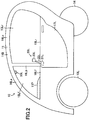
- the outside air introduction system according to the embodiment of the invention is a system for introducing an outside air into an interior space of the ultra-lightweight vehicle and is applied to an ultra-lightweight vehicle 10 shown in FIGs. 1 to 3
- the outside air introduction system according to the embodiment will be referred to as "the embodiment system”.
- the ultra-lightweight vehicle 10 of this embodiment does not have an electric air conditioning apparatus such as an air conditioner capable of ventilating, cooling, or heating the interior space 19 of the ultra-lightweight vehicle 10.
- the embodiment system may be applied to the ultra-lightweight vehicle having the electric air conditioning apparatus.
- the ultra-lightweight vehicle 10 of this embodiment is a small-size vehicle having a capacity of two persons.
- the embodiment system may be applied to the ultra-lightweight vehicle having a capacity of one person or three persons. Therefore, the embodiment system may be applied to the ultra-lightweight vehicle having a capacity of three or less persons.
- the ultra-lightweight vehicle 10 includes a body 11, a left side mirror member or wing mirror member 20L, a right side mirror member or wing mirror member 20R, a left front wheel 13L, a right front wheel 13R, and a rear wheel 14.
- the embodiment system may be applied to the ultra-lightweight vehicle including three or more wheels.
- the body 11 includes a main body 11B and an instrument panel 11P.
- the body 11 further includes a front window glass or front glass 15F, a left A pillar 16La, a left B pillar 16Lb, a left C pillar 16Lc, a left door 17L, a left front window glass 15Lf, a right A pillar 16Ra, a right B pillar 16Rb, a right C pillar 16Rc, a right door 17R, and a right front window glass 15Rf.
- the left A pillar 16La extends curving upwardly and longitudinally from a front side of the body 11 to a rear side of the body 11.
- the right A pillar 16Ra extends curving upwardly and longitudinally from the front side of the body 11 to the rear side of the body 11.
- the left B pillar 16Lb extends generally vertically.
- the right B pillar 16Rb extends generally vertically.
- the left front window glass 15Lf is fitted in a left front window frame 18Lf formed by the left A pillar 16La, the left B pillar 16Lb, and the main body 11B. As described later, the left front window glass 15Lf is movably fitted in the left front window frame 18Lf. A portion of the main body 11B forming the left front window frame 18Lf is a portion of the main body 11B extending generally straight longitudinally.
- the left door 17L includes a window frame 18Lr at an upper area of the left door 17L. A window glass 15Lr is fitted in the window frame 18Lr.
- the right front window glass 15Rf is fitted in a right front window frame 18Rf formed by the right A pillar 16Ra, the right B pillar 16Rb, and the main body 11B. As described later, the right front window glass 15Rf is movably fitted in the right front window frame 18Rf. A portion of the main body 11B forming the right front window frame 18Rf is a portion of the main body 11B extending generally straight longitudinally.
- the right door 17R includes a window frame 18Rr at an upper area of the right door 17R. A window glass 15Rr is fitted in the window frame 18Rr.
- the body 11 defines an interior space 19.
- the interior space 19 is generally closed when the left and right doors 17L and 17R are closed.
- the body 11 includes an outer wall surface having a streamline shape with an apex portion corresponding to a front center portion of the outer wall surface in a width direction of the body 11.
- the instrument panel 11P is mounted to the main body 11B at a front area of the interior space 19.
- the left side mirror member 20L includes a stay portion 21L, a stem portion 22L, and a head portion 23L.
- the stay portion 21L is secured to a front portion of the left door 17L.
- the stem portion 22L is an elongated rod member.
- a lower end of the stem portion 22L is secured to an upper wall surface of the stay portion 21L such that the stem portion 22L extends diagonally leftward, upwardly and outwardly from the upper wall surface of the stay portion 21L.
- the head portion 23L is secured to an upper end of the stem portion 22L.
- a mirror is mounted on a rear wall surface of the head portion 23L. A driver of the ultra-lightweight vehicle 10 can look at a situation left rearward of the ultra-lightweight vehicle 10 by the mirror.
- the right side mirror member 20R includes a stay portion 21R, a stem portion 22R, and a head portion 23R.
- the stay portion 21R is secured to a front portion of the right door 17R.
- the stem portion 22R is an elongated rod member.
- a lower end of the stem portion 22R is secured to an upper wall surface of the stay portion 21R such that the stem portion 22R extends diagonally rightward, upwardly and outwardly from the upper wall surface of the stay portion 21R.
- the head portion 23R is secured to an upper end of the stem portion 22R.
- a mirror is mounted on a rear wall surface of the head portion 23R. A driver of the ultra-lightweight vehicle 10 can look at a situation right rearward of the ultra-lightweight vehicle 10 by the mirror.
- the stay portions 21L and 21R form spaces between the body 11 and the ground or the road.
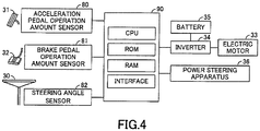
- the ultra-lightweight vehicle 10 includes a steering wheel 30, an acceleration pedal 31, a brake pedal 32, an electric motor 33, an inverter 34, a battery 35, a power steering apparatus 36, an acceleration pedal operation amount sensor 80, a brake pedal operation amount sensor 81, a steering angle sensor 82, and an ECU 90.
- the ultra-lightweight vehicle 10 further includes a seat (not shown) for the driver and a seat (not shown) for a passenger of the ultra-lightweight vehicle 10.
- the seat for the passenger is provided rearward of the seat for the driver.
- the ECU 90 is an electronic control unit or an electronic control circuit having as a main component, a microcomputer including a CPU, a ROM, a RAM, an interface, and the like.
- the steering wheel 30 is turned by hands of the driver for steering the rear wheel 14 as a steered wheel.
- the steering angle sensor 82 detects a steering angle of the steering wheel 30 and outputs a signal indicating the detected steering angle to the ECU 90.
- the acceleration pedal 31 is operated by a foot of the driver for adjusting an acceleration of the ultra-lightweight vehicle 10.
- the acceleration pedal operation amount sensor 80 detects an operation amount of the acceleration pedal 31 and outputs a signal indicating the detected operation amount to the ECU 90.
- the brake pedal 32 is operated by the foot of the driver for adjusting a deceleration of the ultra-lightweight vehicle 10.
- the brake pedal operation amount sensor 81 detects an operation amount of the brake pedal 32 and outputs a signal indicating the detected operation amount to the ECU 90.
- the inverter 34 is electrically connected to the ECU 90.
- the electric motor 33 is connected to the battery 35 through the inverter 34.
- the ultra-lightweight vehicle 10 is driven by rotating the left and right front wheels 13L and 13R, using the electric motor 33 as a driving power source.
- the electric motor 33 is driven by electric power stored in the battery 35.
- FIG. 5 the embodiment system includes a left outside air introduction system and a right outside air introduction system.
- FIG. 5A is a view showing a cross section of a right side part of the body 11 and the like along a vertical plane extending perpendicular to a longitudinal direction of the body 11, viewing from a front side of the body 11, the right side part of the body 11 being a part at a right side of the body 11 in a lateral direction of the body 11.
- FIG. 5A is a view showing a cross section of a right side part of the body 11 and the like along a vertical plane extending perpendicular to a longitudinal direction of the body 11, viewing from a front side of the body 11, the right side part of the body 11 being a part at a right side of the body 11 in a lateral direction of the body 11.
- FIG. 5A is a view showing a cross section of a right side part of the body 11 and the like along a vertical plane extending perpendicular to a longitudinal direction of the body 11, viewing from a front
- 5B is a view showing a cross section of a left side part of the body 11 and the like along the vertical plane extending perpendicular to the longitudinal direction of the body 11, viewing from the front side of the body 11, the left side part of the body 11 being a part at a left side of the body 11 in the lateral direction of the body 11.
- the left outside air introduction system includes a support mechanism 45L.
- the left front window glass 15Lf is supported pivotably outwardly from the body 11 in the lateral direction of the body 11 by the support mechanism 45L.
- the support mechanism 45L includes a pair of window glass support rods 45La, a shaft 45Lb, a bracket 45Lc, and a holder member 45Ld. Although not shown, the support mechanism 45L further includes a pair of body support rods and a coil spring.
- One of the window glass support rods 45La includes a through hole.
- the other window glass support rod 45La also includes a through hole.
- the window glass support rods 45La are secured to an inner lower portion of the left front window glass 15Lf via the bracket 45Lc such that the window glass support rods 45La are spaced apart from each other, and center axes of the through holes of the window glass support rods 45La extend in the longitudinal direction of the body 11 and are aligned with each other.
- the shaft 45Lb is inserted into the through holes of the window glass support rods 45La.
- One of the body support rods of the support mechanism 45L includes a through hole.
- the other body support rod of the support mechanism 45L also includes a through hole.
- the body support rods of the support mechanism 45L are secured to the main body 11B such that the body support rods of the support mechanism 45L are spaced apart from each other, and center axes of the through holes of the body support rods of the support mechanism 45L are aligned with the center axes of the through holes of the window glass support rods 45La.
- the shaft 45Lb is inserted into the through holes of the body support rods of the support mechanism 45L.
- the coil spring of the support mechanism 45L is provided around the shaft 45Lb such that the coil spring of the support mechanism 45L abuts against the bracket 45Lc at one end thereof and against the main body 11B at the other end thereof.
- the coil spring of the support mechanism 45L biases the left front window glass 15Lf via the bracket 45Lc such that the left front window glass 15Lf pivots outwardly from the body 11 in the lateral direction of the body 11, thereby to open.
- a bottom end of the left front window glass 15Lf is housed in the holder member 45Ld.
- the support mechanism 45L includes a mechanism for limiting a range of the left front window glass 15Lf pivoting outwardly from the body 11.
- the right outside air introduction system includes a support mechanism 45R.
- the right front window glass 15Rf is supported pivotably outwardly from the body 11 in the lateral direction of the body 11 by the support mechanism 45R.
- the support mechanism 45R includes a pair of window glass support rods 45Ra, a shaft 45Rb, a bracket 45Rc, and a holder member 45Rd. Although not shown, the support mechanism 45R further includes a pair of body support rods and a coil spring.
- One of the window glass support rods 45Ra includes a through hole.
- the other window glass support rod 45Ra also includes a through hole.
- the window glass support rods 45Ra are secured to an inner lower portion of the right front window glass 15Rf via the bracket 45Rc such that the window glass support rods 45Ra are spaced apart from each other, and center axes of the through holes of the window glass support rods 45Ra extend in the longitudinal direction of the body 11 and are aligned with each other.
- the shaft 45Rb is inserted into the through holes of the window glass support rods 45Ra.
- One of the body support rods of the support mechanism 45R includes a through hole.
- the other body support rod of the support mechanism 45R also includes a through hole.
- the body support rods of the support mechanism 45R are secured to the main body 11B such that the body support rods of the support mechanism 45R are spaced apart from each other, and center axes of the through holes of the body support rods of the support mechanism 45R are aligned with the center axes of the through holes of the window glass support rods 45Ra.
- the shaft 45Rb is inserted into the through holes of the body support rods of the support mechanism 45R.
- the coil spring of the support mechanism 45R is provided around the shaft 45Rb such that the coil spring of the support mechanism 45R abuts against the bracket 45Rc at one end thereof and against the main body 11B at the other end thereof.
- the coil spring of the support mechanism 45R biases the right front window glass 15Rf via the bracket 45Rc such that the right front window glass 15Rf pivots outwardly from the body 11 in the lateral direction of the body 11, thereby to open.
- a bottom end of the right front window glass 15Rf is housed in the holder member 45Rd.
- the support mechanism 45R includes a mechanism for limiting a range of the right front window glass 15Rf pivoting outwardly from the body 11.
- the left outside air introduction system further includes a window glass open/close mechanism 50L.
- the window glass open/close mechanism 50L includes an operation lever 51L, a window glass holding plate 52L, a pair of window glass support rods 53L, a shaft 54L, and a stopper 55L.
- the stopper 55L is secured to an upper portion of the left front window frame 18Lf, in which the left front window glass 15Lf is fitted. As shown in FIG. 5B , when the left front window glass 15Lf is closed, an upper portion of the left front window glass 15Lf abuts against the stopper 55L.
- One of the window glass support rods 53L includes a through hole.
- the other window glass support rod 53L also includes a through hole.
- the window glass support rods 53L are secured to an inner upper portion of the left front window glass 15Lf such that the window glass support rods 53L are spaced apart from each other, and center axes of the through holes of the window glass support rods 53L extend generally in the longitudinal direction of the body 11 and are aligned with each other.
- the shaft 54L is inserted into the through holes of the window glass support rods 53L.
- the operation lever 51L includes a through hole at one end thereof.
- the operation lever 51L is secured to the window glass support rods 53L such that the shaft 54L is inserted into the through hole of the operation lever 51L.
- the operation lever 51L can pivot about a center axis of the shaft 54L.
- the window glass open/close mechanism 50L is provided in the ultra-lightweight vehicle 10 such that the operation lever 51L can be operated by the driver of the ultra-lightweight vehicle 10.
- the window glass holding plate 52L is secured to the operation lever 51L such that the window glass holding plate 52L extends upwardly from near a portion of the operation lever 51L where the through hole of the operation lever 51L is provided.
- the window glass holding plate 52L abuts against or engages one of wall surfaces of the stopper 55L opposite to the other wall surface of the stopper 55L against which the left front window glass 15Lf abuts.
- the left front window glass 15Lf is held at a closed position at which the left front window glass 15Lf is closed. Therefore, the window glass holding plate 52L and the stopper 55L form a holding mechanism for holding the left front window glass 15Lf at the closed position.
- FIG. 6B When the driver pivots the operation lever 51L downwardly and outwardly while the left front window glass 15Lf is held at the closed position, the window glass holding plate 52L disengages from the stopper 55L. As shown in FIG. 6B , when the window glass holding plate 52L disengages from the stopper 55L, the left front window glass 15Lf is forcibly pivoted to an open position, at which the left front window glass 15Lf opens, by a biasing force of the coil spring of the support mechanism 45L to the left front window glass 15Lf. Thereby, the outside air is introduced into the interior space 19. It should be noted that FIG. 6B is similar to FIG. 5B .
- the left front window glass 15Lf is pivoted to the closed position.
- the window glass holding plate 52L is engaged with the stopper 55L by the driver pivoting the operation lever 51L upwardly when the left front window glass 15Lf abuts against the stopper 55L. Thereby, as shown in FIG. 5B , the left front window glass 15Lf is held at the closed position.
- the right outside air introduction system further includes a window glass open/close mechanism 50R.
- the window glass open/close mechanism 50R includes an operation lever 51R, a window glass holding plate 52R, a pair of window glass support rods 53R, a shaft 54R, and a stopper 55R.
- the stopper 55R is secured to an upper portion of the right front window frame 18Rf, in which the right front window glass 15Rf is fitted. As shown in FIG. 5A , when the right front window glass 15Rf is closed, an upper portion of the right front window glass 15Rf abuts against the stopper 55R.
- One of the window glass support rods 53R includes a through hole.
- the other window glass support rod 53R also includes a through hole.
- the window glass support rods 53R are secured to an inner upper portion of the right front window glass 15Rf such that the window glass support rods 53R are spaced apart from each other, and center axes of the through holes of the window glass support rods 53R extend generally in the longitudinal direction of the body 11 and are aligned with each other.
- the shaft 54R is inserted into the through holes of the window glass support rods 53R.
- the operation lever 51R includes a through hole at one end thereof.
- the operation lever 51R is secured to the window glass support rods 53R such that the shaft 54R is inserted into the through hole of the operation lever 51R.
- the operation lever 51R can pivot about a center axis of the shaft 54R.
- the window glass open/close mechanism 50R is provided in the ultra-lightweight vehicle 10 such that the operation lever 51R can be operated by the driver of the ultra-lightweight vehicle 10.
- the window glass holding plate 52R is secured to the operation lever 51R such that the window glass holding plate 52R extends upwardly from near a portion of the operation lever 51R where the through hole of the operation lever 51R is provided.
- the window glass holding plate 52R abuts against or engages one of wall surfaces of the stopper 55R opposite to the other wall surface of the stopper 55R against which the right front window glass 15Rf abuts.
- the right front window glass 15Rf is held at a closed position at which the right front window glass 15Rf is closed. Therefore, the window glass holding plate 52R and the stopper 55R form a holding mechanism for holding the right front window glass 15Rf at the closed position.
- FIG. 6A When the driver pivots the operation lever 51R downwardly and outwardly while the right front window glass 15Rf is held at the closed position, the window glass holding plate 52R disengages from the stopper 55R. As shown in FIG. 6A , when the window glass holding plate 52R disengages from the stopper 55R, the right front window glass 15Rf is forcibly pivoted to an open position, at which the right front window glass 15Rf opens, by a biasing force of the coil spring of the support mechanism 45R to the right front window glass 15Rf. Thereby, the outside air is introduced into the interior space 19. It should be noted that FIG. 6A is similar to FIG. 5A .
- the right front window glass 15Rf is pivoted to the closed position.
- the window glass holding plate 52R is engaged with the stopper 55R by the driver pivoting the operation lever 51R upwardly when the right front window glass 15Rf abuts against the stopper 55R. Thereby, as shown in FIG. 5A , the right front window glass 15Rf is held at the closed position.
- the interior space temperature when a temperature of the interior space 19 (hereinafter, will be referred to as "the interior space temperature") increases to a temperature, at which the driver feels discomfort, the driver can open at least one of the left front window glass 15Lf and the right front window glass 15Rf by operating at least one of the operation lever 51L and the operation lever 51R, thereby introducing the outside air into the interior space 19 to decrease the interior space temperature.
- the driver when the driver desires to prevent the interior space temperature from increasing excessively, the driver can prevent the interior space temperature from increasing excessively by maintaining at least one of the left front window glass 15Lf and the right front window glass 15Rf at the open position.
- the driver can remove a cloud of the window glass by opening at least one of the left front window glass 15Lf and the right front window glass 15Rf.
- the driver can prevent the window glasses 15F, 15Lf, 15Rf, 15Lr, and 15Rr from clouding by maintaining at least one of the left front window glass 15Lf and the right front window glass 15Rf at the open position.
- the driver can prevent the rain from coming into the interior space 19 by operating the operation lever 51L and/or the operation lever 51R to close the left front window glass 15Lf and/or the right front window glass 15Rf.
- the support mechanism 45L of the embodiment system may be provided on the left A pillar 16La or the left B pillar 16Lb.
- the window glass open/close mechanism 50L may be provided at a lower portion of the left front window glass 15Lf in a vertical direction of the body 11 or at a rear portion of the left front window glass 15Lf in the longitudinal direction of the body 11.
- the support mechanism 45R of the embodiment system may be provided on the right A pillar 16Ra or the right B pillar 16Rb.
- the window glass open/close mechanism 50R may be provided at a lower portion of the right front window glass 15Rf in the vertical direction of the body 11 or at a rear portion of the right front window glass 15Rf in the longitudinal direction of the body 11.
- the embodiment system may be configured to pivot the left front window glass 15Lf and the right front window glass 15Rf inwardly of the body 11 in the lateral direction of the body 11.
- the embodiment system may be configured to include only one of the left outside air introduction system and the right air introduction system.
- the embodiment system may be configured to include a device or a member for biasing the operation lever 51L to pivot the operation lever 51L upwardly. Thereby, the operation lever 51L may be prevented from pivoting downwardly when the window glass holding plate 52L engages with the stopper 55L to hold the left front window glass 15Lf at the closed position. Also, the embodiment system may be configured to include a device or a member for biasing the window glass holding plate 52R to pivot the operation lever 51R upwardly. Thereby, the operation lever 51R may be prevented from pivoting downwardly when the window glass holding plate 52R engages with the stopper 55R to hold the right front window glass 15Rf at the closed position.
- the embodiment system may be configured to include a device or a member for opening the left front window glass 15Lf in place of the operation lever 51L. Also, the embodiment system may be configured to include a device or a member for opening the right front window glass 15Rf in place of the operation lever 51R.
- the embodiment system may be configured to include a device or a member for holding the left front window glass 15Lf at the closed position in place of the window glass holding plate 52L. Also, the embodiment system may be configured to include a device or a member for holding the right front window glass 15Rf at the closed position in place of the window glass holding plate 52R. The embodiment system may not include the window glass holding plate 52L when the window glass 15Lf can be held by the other member or device. Also, the embodiment system may not include the window glass holding plate 52R when the window glass 15Rf can be held by the other member or device.
- the embodiment system may be configured to include a device or a member for biasing the left front window glass 15Lf outwardly in the lateral direction of the body 11 in place of the coil spring. Also, the embodiment system may be configured to include a device or a member for biasing the right front window glass 15Rf outwardly in the lateral direction of the body 11 in place of the coil spring. Further, the coil spring for biasing the left front window glass 15Lf outwardly in the lateral direction of the body 11 may be omitted. Also, the coil spring for biasing the right front window glass 15Rf outwardly in the lateral direction of the body 11 may be omitted.
- the operation lever 51L may be provided at any position where a passenger of the ultra-lightweight vehicle 10 other than the driver can operate. Thereby, the passenger can open and close the left front window glass 15Lf.
- the operation lever 51R may be provided at any position where the passenger of the ultra-lightweight vehicle 10 other than the driver can operate. Thereby, the passenger can open and close the right front window glass 15Rf.
- the embodiment system may be used for opening and closing the window glass 15Lr and the window glass 15Rr provided on the left door 17L and the right door 17R, respectively.
Landscapes
- Engineering & Computer Science (AREA)
- Mechanical Engineering (AREA)
- Window Of Vehicle (AREA)
Claims (7)
- Außenlufteinführsystem zum Einführen von Außenluft in einen allgemein geschlossenen Innenraum (19) eines ultraleichten Fahrzeugs (10), wobei das ultraleichte Fahrzeug (10) eine Karosserie (11) aufweist, die mit mindestens einem Fensterrahmen (18Lf, 18Rf) und mindestens einer Fensterscheibe (15Lf, 15Rf) versehen ist, die in den mindestens einen Fensterrahmen (18Lf, 18Rf) eingesetzt ist, wobei die Karosserie (11) und die mindestens eine Fensterscheibe (15Lf, 15Rf) den allgemein geschlossenen Innenraum (19) definieren,
wobei das Außenlufteinführsystem umfasst:mindestens einen Stützmechanismus (45L, 45R) zum schwenkbaren Abstützen der mindestens einen Fensterscheibe (15Lf, 15Rf) n der Karosserie (11) undmindestens ein Fensterscheiben-Öffnungs-Schließmechanismus (50L, 50R), der dazu vorgesehen ist, von einem Fahrer des ultraleichten Fahrzeugs (10) betätigt zu werden, um die mindestens eine Fensterscheibe (15Lf, 15Rf) zu schwenken, um die mindestens eine Fensterscheibe (15Lf, 15Rf) zu öffnen und zu schließen,wobei der mindestens eine Fensterscheiben-Öffnungs-Schließmechanismus (50L, 50R) mindestens einen Haltemechanismus (52L, 55L, 52R, 55R) zum Halten der mindestens einen Fensterscheibe (15Lf, 15Rf) in einer geschlossenen Position, in der die mindestens eine Fensterscheibe (15Lf, 15Rf) geschlossen ist, umfasst,
dadurch gekennzeichnet,dass der mindestens eine Haltemechanismus (52L, 55L, 52R, 55R) mindestens einen vom Fahrer betätigten Betätigungshebel (51L, 51R) aufweist, der nach oben wirkt, um die mindestens eine Fensterscheibe (15Lf, 15Rf) in der geschlossenen Position zu halten, und nach unten wirkt, um die mindestens eine Fensterscheibe (15Lf, 15Rf) freizugeben,dass der mindestens eine Betätigungshebel (51L, 51R) an Fensterscheiben-Tragstangen (53L, 53R) über eine Welle (54L, 54R), die in Durchgangsöffnungen der Tragstangen (53L, 53R) und des wenigstens einen Betätigungshebels (51L, 51R) eingesetzt ist, schwenkbar befestigt ist, wobei die Fensterscheiben-Tragstangen (53L, 53R) an einem inneren oberen Abschnitt der mindestens einen Fensterscheibe (15Lf, 15Rf) befestigt sind,dass der mindestens eine Haltemechanismus (52L, 55L, 52R, 55R) ferner umfasst:mindestens einen Anschlag (55L, 55R), der an einem oberen Abschnitt des mindestens einen Fensterrahmens (18Lf, 18 Rf) befestigt ist, undmindestens eine Fensterscheibenhalteplatte (52L, 52R), die an dem mindestens einen Betätigungshebel (51L, 51R) befestigt ist, unddass, wenn die mindestens eine Fensterscheibe (15Ff, 15Rf) geschlossen ist, die mindestens eine Fensterscheibe (15Lf, 15Rf) an einer ersten Wandfläche des mindestens einen Anschlags (55L, 55R) anliegt und die mindestens eine Fensterscheibenhalteplatte (52L, 52R) an einer der ersten Wandfläche gegenüberliegenden zweiten Wandfläche des mindestens einen Anschlags (55L 55R) anliegt oder angreift, wobei die mindestens eine Fensterscheibenhalteplatte (52L, 52R) so konfiguriert ist, dass sie mit dem mindestens einen Anschlag (55L, 55R) in Eingriff gebracht wird, indem der Fahrer den mindestens einen Betätigungshebel (51L, 51R) nach oben schwenkt, wenn die mindestens eine Fensterscheibe (15Lf, 15Rf) gegen den mindestens einen Anschlag (55L, 55R) stößt. - Außenlufteinführsystem nach Anspruch 1, dadurch gekennzeichnet, dass der mindestens eine Stützmechanismus (45L, 45R) die mindestens eine Fensterscheibe (15Lf, 15Rf) an der Karosserie (11) an einem unteren Abschnitt der mindestens einen Fensterscheibe (15Lf, 15Rf) abstützt.
- Außenlufteinführsystem nach Anspruch 1 oder 2, dadurch gekennzeichnet, dass der mindestens eine Stützmechanismus (45L, 45R) die mindestens eine Fensterscheibe (15Lf, 15Rf) schwenkbar an der Karosserie (11) abstützt, um die mindestens eine Fensterscheibe (15Lf, 15Rf) von der Karosserie (11) nach außen zu schwenken.
- Außenlufteinführsystem nach einem der Ansprüche 1 bis 3, dadurch gekennzeichnet, dass der mindestens eine Fensterrahmen (18Lf, 18Rf) an einem linken oder rechten Seitenteil der Karosserie (11) vorgesehen ist.
- Außenlufteinführsystem nach Anspruch 1, dadurch gekennzeichnet,
dass der mindestens eine Fensterrahmen (18Lf, 18Rf) einen linken Fensterrahmen (18Lf), der an einem linken Seitenteil der Karosserie (11) vorgesehen ist, und einen rechten Fensterrahmen (18Rf), der an einem rechten Seitenteil der Karosserie (11) vorgesehen ist, umfasst,
dass die mindestens eine Fensterscheibe (15Lf, 15Rf) eine linke Fensterscheibe (15Lf), die an dem linken Fensterrahmen (18Lf) angebracht ist, und eine rechte Fensterscheibe (15Rf), die an dem rechten Fensterrahmen (18Rf) angebracht ist, umfasst, und
dass der mindestens eine Stützmechanismus (45L, 45R) einen linken Stützmechanismus (45L) zum schwenkbaren Abstützen der linken Fensterscheibe (15Lf) an der Karosserie (11) und einen rechten Stützmechanismus (45R) zum schwenkbaren Abstützen der rechten Fensterscheibe (15Rf) an der Karosserie (11) umfasst,
dass das Außenlufteinführsystem einen linken Fensterscheiben-Öffnungs-Schließmechanismus (50L), der vorgesehen ist, um von einem Fahrer des ultraleichten Fahrzeugs (10) betätigt zu werden, um die linke Fensterscheibe (15Lf) zu schwenken, um die linke Fensterscheibe (15Lf) zu öffnen und zu schließen, und einen rechten Fensterscheiben-Öffnungs-Schließmechanismus (50R) umfasst, der vorgesehen ist, um von dem Fahrer des ultraleichten Fahrzeugs (10) betätigt zu werden, um die rechte Fensterscheibe (15Rf) zu schwenken, um die rechte Fensterscheibe (15Rf) zu öffnen und zu schließen,
dass der linke Fensterscheiben-Öffnungs-Schließmechanismus (50L) einen linken Haltemechanismus (52L, 55L) zum Halten der linken Fensterscheibe (15Lf) in einer geschlossenen Position, in der die linke Fensterscheibe (15Lf) geschlossen ist, umfasst,
dass der rechte Fensterscheiben-Öffnungs-Schließmechanismus (50R) einen rechten Haltemechanismus (52R, 55R) zum Halten der rechten Fensterscheibe (15Rf) in einer geschlossenen Position, in der die rechte Fensterscheibe (15Rf) geschlossen ist, umfasst,
dass der linke Haltemechanismus (52L, 55L) einen linken Betätigungshebel (51L) umfasst, der vom Fahrer nach oben, um die linke Fensterscheibe (15Lf) in der geschlossenen Position zu halten, und nach unten betätigt wird, um die linke Fensterscheibe (15Lf) freizugeben, und
dass der rechte Haltemechanismus (52R, 55R) einen rechten Betätigungshebel (51R) umfasst, der vom Fahrer nach oben, um die rechte Fensterscheibe (15Rf) in der geschlossenen Position zu halten, und nach unten betätigt wird, um die rechte Fensterscheibe (15Rf) freizugeben,
dass der linke Betätigungshebel (51L) an Fensterscheiben-Tragstangen (53L) über eine Welle (54L), die in Durchgangsöffnungen der Tragstangen (53L) und des Betätigungshebels (51L) eingesetzt ist, schwenkbar befestigt ist, wobei die Fensterscheiben-Tragstangen (53L) an einem inneren oberen Abschnitt der linken Fensterscheibe (15Lf) befestigt sind,
dass der rechte Betätigungshebel (51R) an Fensterscheiben-Tragstangen (53R) über eine Welle (54R), die in Durchgangsöffnungen der Tragstangen (53R) und des Betätigungshebels (51R) eingesetzt ist, schwenkbar befestigt ist, wobei die Fensterscheiben-Tragstangen (53R) an einem inneren oberen Abschnitt der rechten Fensterscheibe (15Lf) befestigt sind,
dass der linke Haltemechanismus (52L, 55L) ferner umfasst:einen linken Anschlag (55L), der an einem oberen Teil des linken Fensterrahmens (18Lf) befestigt ist, undeine linke Fensterscheibenhalteplatte (52L), die am linken Betätigungshebel (51L) befestigt ist,dass der rechte Haltemechanismus (52R, 55R) ferner umfasst:einen rechten Anschlag (55R), der an einem oberen Teil des rechten Fensterrahmens (18Rf) befestigt ist, undeine rechte Fensterscheibenhalteplatte (52R), die am rechten Betätigungshebel (51R) befestigt ist,dass, wenn die linke Fensterscheibe (15Ff) geschlossen ist, die linke Fensterscheibe (15Lf) an einer ersten Wandfläche des linken Anschlags (55L) anliegt und die linke Fensterscheibenhalteplatte (52L) an einer zweiten Wandfläche des linken Anschlags (55L), die der ersten Wandfläche gegenüberliegt, anliegt oder an dieser angreift, wobei die linke Fensterscheibenhalteplatte (52L) so konfiguriert ist, dass sie mit dem linken Anschlag (55L) in Eingriff gebracht wird, in dem der Fahrer den linken Betätigungshebel (51L) nach oben schwenkt, wenn die linke Fensterscheibe (15Lf) gegen den linken Anschlag (55L) stößt, und
dass, wenn die rechte Fensterscheibe (15Rf) geschlossen ist, die rechte Fensterscheibe (15Tf) an einer ersten Wandfläche des rechten Anschlags (55R) anliegt und die rechte Fensterscheibenhalteplatte (52R) an einer zweiten Wandfläche des rechten Anschlags (55R), die der ersten Wandfläche gegenüberliegt, anliegt oder an dieser angreift, wobei die rechte Fensterscheibenhalteplatte (52R) so konfiguriert ist, dass sie mit dem rechten Anschlag (55R) in Eingriff gebracht wird, in dem der Fahrer den rechten Betätigungshebel (51R) nach oben schwenkt, wenn die rechte Fensterscheibe (15Rf) gegen den rechten Anschlag (55R) stößt. - Außenlufteinführsystem nach Anspruch 5, dadurch gekennzeichnet, dass
der linke Stützmechanismus (45L) die linke Fensterscheibe (15Lf) an der Karosserie (11) an einem unteren Abschnitt der linken Fensterscheibe (15Lf) stützt,
der rechte Stützmechanismus (45R) die rechte Fensterscheibe (15Rf) an der Karosserie (11) an einem unteren Teil der rechten Fensterscheibe (15Rf) abstützt. - Außenlufteinführsystem nach Anspruch 5 oder 6, dadurch gekennzeichnet, dass
der linke Stützmechanismus (45L) die linke Fensterscheibe (15Lf) schwenkbar an der Karosserie (11) abstützt, um die linke Fensterscheibe (15Lf) von der Karosserie (11) nach außen zu schwenken, und
der rechte Stützmechanismus (45R) die rechte Fensterscheibe (15Rf) schwenkbar an der Karosserie (11) abstützt, um die rechte Fensterscheibe (15Rf) von der Karosserie (11) nach außen zu schwenken.
Applications Claiming Priority (1)
| Application Number | Priority Date | Filing Date | Title |
|---|---|---|---|
| JP2017165074A JP6801611B2 (ja) | 2017-08-30 | 2017-08-30 | 超小型モビリティの外気導入構造 |
Publications (2)
| Publication Number | Publication Date |
|---|---|
| EP3450232A1 EP3450232A1 (de) | 2019-03-06 |
| EP3450232B1 true EP3450232B1 (de) | 2020-12-02 |
Family
ID=63449377
Family Applications (1)
| Application Number | Title | Priority Date | Filing Date |
|---|---|---|---|
| EP18191718.8A Not-in-force EP3450232B1 (de) | 2017-08-30 | 2018-08-30 | Klappfenster eines ultraleichten fahrzeugs |
Country Status (2)
| Country | Link |
|---|---|
| EP (1) | EP3450232B1 (de) |
| JP (1) | JP6801611B2 (de) |
Family Cites Families (5)
| Publication number | Priority date | Publication date | Assignee | Title |
|---|---|---|---|---|
| US2066432A (en) * | 1934-08-01 | 1937-01-05 | Fulton Co | Air deflector |
| JPS60248435A (ja) * | 1984-05-23 | 1985-12-09 | Daihatsu Motor Co Ltd | 脱着式開閉体のロツク装置 |
| JPS63104211U (de) | 1986-12-26 | 1988-07-06 | ||
| JPH06100040B2 (ja) * | 1989-01-26 | 1994-12-12 | ダイキョー・ベバスト株式会社 | 着脱式側部ウインド開閉装置のロック装置 |
| FR2926494B1 (fr) * | 2008-01-18 | 2010-03-26 | Peugeot Citroen Automobiles Sa | Vitrage de porte basculant vers le bas |
-
2017
- 2017-08-30 JP JP2017165074A patent/JP6801611B2/ja not_active Expired - Fee Related
-
2018
- 2018-08-30 EP EP18191718.8A patent/EP3450232B1/de not_active Not-in-force
Non-Patent Citations (1)
| Title |
|---|
| None * |
Also Published As
| Publication number | Publication date |
|---|---|
| JP6801611B2 (ja) | 2020-12-16 |
| JP2019043185A (ja) | 2019-03-22 |
| EP3450232A1 (de) | 2019-03-06 |
Similar Documents
| Publication | Publication Date | Title |
|---|---|---|
| US8818700B2 (en) | Motorised vehicle with controlled inclination | |
| US8840131B1 (en) | Three-wheeled vehicle | |
| US20100324808A1 (en) | Motorised vehicle with controlled inclination | |
| US9266413B2 (en) | Opening and/or closing device | |
| CN110785342B (zh) | 摆动式车辆 | |
| US7974755B2 (en) | Motor vehicle acoustic noise reduction system | |
| JP2020505272A (ja) | 自己平衡型車両装置及びその制御方法 | |
| CN101722821B (zh) | 具有剪刀门的机动车辆 | |
| CN113147549A (zh) | 一种乘员共享型控温副仪表台扶手箱 | |
| KR100862498B1 (ko) | 차량용 에어벤트 구조 | |
| JPS60163773A (ja) | 自動車のリヤスポイラ | |
| EP2500192A1 (de) | Fahrzeugklimaanlage | |
| EP3450232A1 (de) | Klappfenster eines ultraleichten fahrzeugs | |
| CN213057332U (zh) | 微型厢式机动车的车体结构及两轮机动车 | |
| JP6791069B2 (ja) | 超小型モビリティの外気導入構造 | |
| JP6915458B2 (ja) | 超小型モビリティの外気導入構造 | |
| US11858319B2 (en) | Automatic sunvisor assembly | |
| JP2024157189A (ja) | 車両 | |
| EP2085300A2 (de) | Stabilisierungsmittel für Zweirad-Fahrzeug | |
| EP1768890B1 (de) | Verbesserungen für fahrgastservicefahrzeuge | |
| US3724577A (en) | Cafly | |
| CN113302117A (zh) | 扰流器装置、具有扰流器装置的车辆、运行扰流器装置的方法 | |
| CN201231797Y (zh) | 轻便舱旅游车 | |
| US20040057133A1 (en) | Structural improvement of vehicular tail ground mirror | |
| US20050146160A1 (en) | Home utility management vehicle mini van or HUM V Mini Van |
Legal Events
| Date | Code | Title | Description |
|---|---|---|---|
| PUAI | Public reference made under article 153(3) epc to a published international application that has entered the european phase |
Free format text: ORIGINAL CODE: 0009012 |
|
| STAA | Information on the status of an ep patent application or granted ep patent |
Free format text: STATUS: REQUEST FOR EXAMINATION WAS MADE |
|
| 17P | Request for examination filed |
Effective date: 20180830 |
|
| AK | Designated contracting states |
Kind code of ref document: A1 Designated state(s): AL AT BE BG CH CY CZ DE DK EE ES FI FR GB GR HR HU IE IS IT LI LT LU LV MC MK MT NL NO PL PT RO RS SE SI SK SM TR |
|
| AX | Request for extension of the european patent |
Extension state: BA ME |
|
| GRAP | Despatch of communication of intention to grant a patent |
Free format text: ORIGINAL CODE: EPIDOSNIGR1 |
|
| STAA | Information on the status of an ep patent application or granted ep patent |
Free format text: STATUS: GRANT OF PATENT IS INTENDED |
|
| INTG | Intention to grant announced |
Effective date: 20200722 |
|
| GRAS | Grant fee paid |
Free format text: ORIGINAL CODE: EPIDOSNIGR3 |
|
| GRAA | (expected) grant |
Free format text: ORIGINAL CODE: 0009210 |
|
| STAA | Information on the status of an ep patent application or granted ep patent |
Free format text: STATUS: THE PATENT HAS BEEN GRANTED |
|
| AK | Designated contracting states |
Kind code of ref document: B1 Designated state(s): AL AT BE BG CH CY CZ DE DK EE ES FI FR GB GR HR HU IE IS IT LI LT LU LV MC MK MT NL NO PL PT RO RS SE SI SK SM TR |
|
| REG | Reference to a national code |
Ref country code: GB Ref legal event code: FG4D |
|
| REG | Reference to a national code |
Ref country code: AT Ref legal event code: REF Ref document number: 1340520 Country of ref document: AT Kind code of ref document: T Effective date: 20201215 Ref country code: CH Ref legal event code: EP |
|
| REG | Reference to a national code |
Ref country code: DE Ref legal event code: R096 Ref document number: 602018010316 Country of ref document: DE |
|
| REG | Reference to a national code |
Ref country code: IE Ref legal event code: FG4D |
|
| PG25 | Lapsed in a contracting state [announced via postgrant information from national office to epo] |
Ref country code: FI Free format text: LAPSE BECAUSE OF FAILURE TO SUBMIT A TRANSLATION OF THE DESCRIPTION OR TO PAY THE FEE WITHIN THE PRESCRIBED TIME-LIMIT Effective date: 20201202 Ref country code: RS Free format text: LAPSE BECAUSE OF FAILURE TO SUBMIT A TRANSLATION OF THE DESCRIPTION OR TO PAY THE FEE WITHIN THE PRESCRIBED TIME-LIMIT Effective date: 20201202 Ref country code: GR Free format text: LAPSE BECAUSE OF FAILURE TO SUBMIT A TRANSLATION OF THE DESCRIPTION OR TO PAY THE FEE WITHIN THE PRESCRIBED TIME-LIMIT Effective date: 20210303 Ref country code: NO Free format text: LAPSE BECAUSE OF FAILURE TO SUBMIT A TRANSLATION OF THE DESCRIPTION OR TO PAY THE FEE WITHIN THE PRESCRIBED TIME-LIMIT Effective date: 20210302 |
|
| REG | Reference to a national code |
Ref country code: NL Ref legal event code: MP Effective date: 20201202 |
|
| REG | Reference to a national code |
Ref country code: AT Ref legal event code: MK05 Ref document number: 1340520 Country of ref document: AT Kind code of ref document: T Effective date: 20201202 |
|
| PG25 | Lapsed in a contracting state [announced via postgrant information from national office to epo] |
Ref country code: SE Free format text: LAPSE BECAUSE OF FAILURE TO SUBMIT A TRANSLATION OF THE DESCRIPTION OR TO PAY THE FEE WITHIN THE PRESCRIBED TIME-LIMIT Effective date: 20201202 Ref country code: LV Free format text: LAPSE BECAUSE OF FAILURE TO SUBMIT A TRANSLATION OF THE DESCRIPTION OR TO PAY THE FEE WITHIN THE PRESCRIBED TIME-LIMIT Effective date: 20201202 Ref country code: PL Free format text: LAPSE BECAUSE OF FAILURE TO SUBMIT A TRANSLATION OF THE DESCRIPTION OR TO PAY THE FEE WITHIN THE PRESCRIBED TIME-LIMIT Effective date: 20201202 Ref country code: BG Free format text: LAPSE BECAUSE OF FAILURE TO SUBMIT A TRANSLATION OF THE DESCRIPTION OR TO PAY THE FEE WITHIN THE PRESCRIBED TIME-LIMIT Effective date: 20210302 |
|
| PG25 | Lapsed in a contracting state [announced via postgrant information from national office to epo] |
Ref country code: HR Free format text: LAPSE BECAUSE OF FAILURE TO SUBMIT A TRANSLATION OF THE DESCRIPTION OR TO PAY THE FEE WITHIN THE PRESCRIBED TIME-LIMIT Effective date: 20201202 Ref country code: NL Free format text: LAPSE BECAUSE OF FAILURE TO SUBMIT A TRANSLATION OF THE DESCRIPTION OR TO PAY THE FEE WITHIN THE PRESCRIBED TIME-LIMIT Effective date: 20201202 |
|
| REG | Reference to a national code |
Ref country code: LT Ref legal event code: MG9D |
|
| PG25 | Lapsed in a contracting state [announced via postgrant information from national office to epo] |
Ref country code: EE Free format text: LAPSE BECAUSE OF FAILURE TO SUBMIT A TRANSLATION OF THE DESCRIPTION OR TO PAY THE FEE WITHIN THE PRESCRIBED TIME-LIMIT Effective date: 20201202 Ref country code: CZ Free format text: LAPSE BECAUSE OF FAILURE TO SUBMIT A TRANSLATION OF THE DESCRIPTION OR TO PAY THE FEE WITHIN THE PRESCRIBED TIME-LIMIT Effective date: 20201202 Ref country code: SM Free format text: LAPSE BECAUSE OF FAILURE TO SUBMIT A TRANSLATION OF THE DESCRIPTION OR TO PAY THE FEE WITHIN THE PRESCRIBED TIME-LIMIT Effective date: 20201202 Ref country code: LT Free format text: LAPSE BECAUSE OF FAILURE TO SUBMIT A TRANSLATION OF THE DESCRIPTION OR TO PAY THE FEE WITHIN THE PRESCRIBED TIME-LIMIT Effective date: 20201202 Ref country code: RO Free format text: LAPSE BECAUSE OF FAILURE TO SUBMIT A TRANSLATION OF THE DESCRIPTION OR TO PAY THE FEE WITHIN THE PRESCRIBED TIME-LIMIT Effective date: 20201202 Ref country code: PT Free format text: LAPSE BECAUSE OF FAILURE TO SUBMIT A TRANSLATION OF THE DESCRIPTION OR TO PAY THE FEE WITHIN THE PRESCRIBED TIME-LIMIT Effective date: 20210405 Ref country code: SK Free format text: LAPSE BECAUSE OF FAILURE TO SUBMIT A TRANSLATION OF THE DESCRIPTION OR TO PAY THE FEE WITHIN THE PRESCRIBED TIME-LIMIT Effective date: 20201202 |
|
| PG25 | Lapsed in a contracting state [announced via postgrant information from national office to epo] |
Ref country code: AT Free format text: LAPSE BECAUSE OF FAILURE TO SUBMIT A TRANSLATION OF THE DESCRIPTION OR TO PAY THE FEE WITHIN THE PRESCRIBED TIME-LIMIT Effective date: 20201202 |
|
| REG | Reference to a national code |
Ref country code: DE Ref legal event code: R097 Ref document number: 602018010316 Country of ref document: DE |
|
| PG25 | Lapsed in a contracting state [announced via postgrant information from national office to epo] |
Ref country code: IS Free format text: LAPSE BECAUSE OF FAILURE TO SUBMIT A TRANSLATION OF THE DESCRIPTION OR TO PAY THE FEE WITHIN THE PRESCRIBED TIME-LIMIT Effective date: 20210402 |
|
| PLBE | No opposition filed within time limit |
Free format text: ORIGINAL CODE: 0009261 |
|
| STAA | Information on the status of an ep patent application or granted ep patent |
Free format text: STATUS: NO OPPOSITION FILED WITHIN TIME LIMIT |
|
| PG25 | Lapsed in a contracting state [announced via postgrant information from national office to epo] |
Ref country code: IT Free format text: LAPSE BECAUSE OF FAILURE TO SUBMIT A TRANSLATION OF THE DESCRIPTION OR TO PAY THE FEE WITHIN THE PRESCRIBED TIME-LIMIT Effective date: 20201202 Ref country code: AL Free format text: LAPSE BECAUSE OF FAILURE TO SUBMIT A TRANSLATION OF THE DESCRIPTION OR TO PAY THE FEE WITHIN THE PRESCRIBED TIME-LIMIT Effective date: 20201202 |
|
| 26N | No opposition filed |
Effective date: 20210903 |
|
| PG25 | Lapsed in a contracting state [announced via postgrant information from national office to epo] |
Ref country code: DK Free format text: LAPSE BECAUSE OF FAILURE TO SUBMIT A TRANSLATION OF THE DESCRIPTION OR TO PAY THE FEE WITHIN THE PRESCRIBED TIME-LIMIT Effective date: 20201202 Ref country code: SI Free format text: LAPSE BECAUSE OF FAILURE TO SUBMIT A TRANSLATION OF THE DESCRIPTION OR TO PAY THE FEE WITHIN THE PRESCRIBED TIME-LIMIT Effective date: 20201202 |
|
| PGFP | Annual fee paid to national office [announced via postgrant information from national office to epo] |
Ref country code: DE Payment date: 20210720 Year of fee payment: 4 |
|
| PG25 | Lapsed in a contracting state [announced via postgrant information from national office to epo] |
Ref country code: ES Free format text: LAPSE BECAUSE OF FAILURE TO SUBMIT A TRANSLATION OF THE DESCRIPTION OR TO PAY THE FEE WITHIN THE PRESCRIBED TIME-LIMIT Effective date: 20201202 |
|
| REG | Reference to a national code |
Ref country code: CH Ref legal event code: PL |
|
| PG25 | Lapsed in a contracting state [announced via postgrant information from national office to epo] |
Ref country code: MC Free format text: LAPSE BECAUSE OF FAILURE TO SUBMIT A TRANSLATION OF THE DESCRIPTION OR TO PAY THE FEE WITHIN THE PRESCRIBED TIME-LIMIT Effective date: 20201202 |
|
| REG | Reference to a national code |
Ref country code: BE Ref legal event code: MM Effective date: 20210831 |
|
| PG25 | Lapsed in a contracting state [announced via postgrant information from national office to epo] |
Ref country code: LI Free format text: LAPSE BECAUSE OF NON-PAYMENT OF DUE FEES Effective date: 20210831 Ref country code: CH Free format text: LAPSE BECAUSE OF NON-PAYMENT OF DUE FEES Effective date: 20210831 |
|
| PG25 | Lapsed in a contracting state [announced via postgrant information from national office to epo] |
Ref country code: IS Free format text: LAPSE BECAUSE OF FAILURE TO SUBMIT A TRANSLATION OF THE DESCRIPTION OR TO PAY THE FEE WITHIN THE PRESCRIBED TIME-LIMIT Effective date: 20210402 Ref country code: LU Free format text: LAPSE BECAUSE OF NON-PAYMENT OF DUE FEES Effective date: 20210830 |
|
| PG25 | Lapsed in a contracting state [announced via postgrant information from national office to epo] |
Ref country code: IE Free format text: LAPSE BECAUSE OF NON-PAYMENT OF DUE FEES Effective date: 20210830 Ref country code: FR Free format text: LAPSE BECAUSE OF NON-PAYMENT OF DUE FEES Effective date: 20210831 Ref country code: BE Free format text: LAPSE BECAUSE OF NON-PAYMENT OF DUE FEES Effective date: 20210831 |
|
| REG | Reference to a national code |
Ref country code: DE Ref legal event code: R119 Ref document number: 602018010316 Country of ref document: DE |
|
| GBPC | Gb: european patent ceased through non-payment of renewal fee |
Effective date: 20220830 |
|
| PG25 | Lapsed in a contracting state [announced via postgrant information from national office to epo] |
Ref country code: CY Free format text: LAPSE BECAUSE OF FAILURE TO SUBMIT A TRANSLATION OF THE DESCRIPTION OR TO PAY THE FEE WITHIN THE PRESCRIBED TIME-LIMIT Effective date: 20201202 |
|
| PG25 | Lapsed in a contracting state [announced via postgrant information from national office to epo] |
Ref country code: HU Free format text: LAPSE BECAUSE OF FAILURE TO SUBMIT A TRANSLATION OF THE DESCRIPTION OR TO PAY THE FEE WITHIN THE PRESCRIBED TIME-LIMIT; INVALID AB INITIO Effective date: 20180830 Ref country code: DE Free format text: LAPSE BECAUSE OF NON-PAYMENT OF DUE FEES Effective date: 20230301 |
|
| PG25 | Lapsed in a contracting state [announced via postgrant information from national office to epo] |
Ref country code: GB Free format text: LAPSE BECAUSE OF NON-PAYMENT OF DUE FEES Effective date: 20220830 |
|
| PG25 | Lapsed in a contracting state [announced via postgrant information from national office to epo] |
Ref country code: MK Free format text: LAPSE BECAUSE OF FAILURE TO SUBMIT A TRANSLATION OF THE DESCRIPTION OR TO PAY THE FEE WITHIN THE PRESCRIBED TIME-LIMIT Effective date: 20201202 |
|
| PG25 | Lapsed in a contracting state [announced via postgrant information from national office to epo] |
Ref country code: MT Free format text: LAPSE BECAUSE OF FAILURE TO SUBMIT A TRANSLATION OF THE DESCRIPTION OR TO PAY THE FEE WITHIN THE PRESCRIBED TIME-LIMIT Effective date: 20201202 |
|
| PG25 | Lapsed in a contracting state [announced via postgrant information from national office to epo] |
Ref country code: TR Free format text: LAPSE BECAUSE OF FAILURE TO SUBMIT A TRANSLATION OF THE DESCRIPTION OR TO PAY THE FEE WITHIN THE PRESCRIBED TIME-LIMIT Effective date: 20201202 |