EP3450199A1 - Vehicle wheel - Google Patents
Vehicle wheel Download PDFInfo
- Publication number
- EP3450199A1 EP3450199A1 EP17789935.8A EP17789935A EP3450199A1 EP 3450199 A1 EP3450199 A1 EP 3450199A1 EP 17789935 A EP17789935 A EP 17789935A EP 3450199 A1 EP3450199 A1 EP 3450199A1
- Authority
- EP
- European Patent Office
- Prior art keywords
- air chamber
- bracket
- hole
- wheel
- chamber bracket
- Prior art date
- Legal status (The legal status is an assumption and is not a legal conclusion. Google has not performed a legal analysis and makes no representation as to the accuracy of the status listed.)
- Withdrawn
Links
- 230000008878 coupling Effects 0.000 claims abstract description 16
- 238000010168 coupling process Methods 0.000 claims abstract description 16
- 238000005859 coupling reaction Methods 0.000 claims abstract description 16
- 238000001746 injection moulding Methods 0.000 abstract description 5
- 230000000694 effects Effects 0.000 abstract description 4
- 230000007423 decrease Effects 0.000 abstract 1
- 239000011347 resin Substances 0.000 abstract 1
- 229920005989 resin Polymers 0.000 abstract 1
- 229910052782 aluminium Inorganic materials 0.000 description 4
- XAGFODPZIPBFFR-UHFFFAOYSA-N aluminium Chemical compound [Al] XAGFODPZIPBFFR-UHFFFAOYSA-N 0.000 description 4
- 238000010586 diagram Methods 0.000 description 4
- 238000000034 method Methods 0.000 description 3
- 239000004840 adhesive resin Substances 0.000 description 2
- 229920006223 adhesive resin Polymers 0.000 description 2
- 239000013013 elastic material Substances 0.000 description 2
- 238000005516 engineering process Methods 0.000 description 2
- 238000002347 injection Methods 0.000 description 2
- 239000007924 injection Substances 0.000 description 2
- 229910052751 metal Inorganic materials 0.000 description 2
- 239000002184 metal Substances 0.000 description 2
- 238000000465 moulding Methods 0.000 description 2
- 229920003002 synthetic resin Polymers 0.000 description 2
- 239000000057 synthetic resin Substances 0.000 description 2
- 239000011358 absorbing material Substances 0.000 description 1
- 230000001133 acceleration Effects 0.000 description 1
- 239000004411 aluminium Substances 0.000 description 1
- 239000000284 extract Substances 0.000 description 1
- 230000005484 gravity Effects 0.000 description 1
- 239000011796 hollow space material Substances 0.000 description 1
- 235000015250 liver sausages Nutrition 0.000 description 1
- 239000000203 mixture Substances 0.000 description 1
- 238000005192 partition Methods 0.000 description 1
- 238000007634 remodeling Methods 0.000 description 1
- 239000000126 substance Substances 0.000 description 1
- 230000002889 sympathetic effect Effects 0.000 description 1
- 230000008685 targeting Effects 0.000 description 1
Images

Classifications
-
- B—PERFORMING OPERATIONS; TRANSPORTING
- B60—VEHICLES IN GENERAL
- B60B—VEHICLE WHEELS; CASTORS; AXLES FOR WHEELS OR CASTORS; INCREASING WHEEL ADHESION
- B60B21/00—Rims
- B60B21/12—Appurtenances, e.g. lining bands
-
- B—PERFORMING OPERATIONS; TRANSPORTING
- B60—VEHICLES IN GENERAL
- B60B—VEHICLE WHEELS; CASTORS; AXLES FOR WHEELS OR CASTORS; INCREASING WHEEL ADHESION
- B60B25/00—Rims built-up of several main parts ; Locking means for the rim parts
- B60B25/002—Rims split in circumferential direction
-
- B—PERFORMING OPERATIONS; TRANSPORTING
- B60—VEHICLES IN GENERAL
- B60C—VEHICLE TYRES; TYRE INFLATION; TYRE CHANGING; CONNECTING VALVES TO INFLATABLE ELASTIC BODIES IN GENERAL; DEVICES OR ARRANGEMENTS RELATED TO TYRES
- B60C19/00—Tyre parts or constructions not otherwise provided for
-
- B—PERFORMING OPERATIONS; TRANSPORTING
- B60—VEHICLES IN GENERAL
- B60C—VEHICLE TYRES; TYRE INFLATION; TYRE CHANGING; CONNECTING VALVES TO INFLATABLE ELASTIC BODIES IN GENERAL; DEVICES OR ARRANGEMENTS RELATED TO TYRES
- B60C19/00—Tyre parts or constructions not otherwise provided for
- B60C19/002—Noise damping elements provided in the tyre structure or attached thereto, e.g. in the tyre interior
-
- B—PERFORMING OPERATIONS; TRANSPORTING
- B60—VEHICLES IN GENERAL
- B60B—VEHICLE WHEELS; CASTORS; AXLES FOR WHEELS OR CASTORS; INCREASING WHEEL ADHESION
- B60B2900/00—Purpose of invention
- B60B2900/10—Reduction of
- B60B2900/131—Vibrations
-
- B—PERFORMING OPERATIONS; TRANSPORTING
- B60—VEHICLES IN GENERAL
- B60B—VEHICLE WHEELS; CASTORS; AXLES FOR WHEELS OR CASTORS; INCREASING WHEEL ADHESION
- B60B2900/00—Purpose of invention
- B60B2900/10—Reduction of
- B60B2900/133—Noise
Definitions
- a vehicle Normally, a vehicle comprises structure which supports vehicle body by air filling derived by coupling inner sphere of tire with inner parts of rim provided at wheel. While driving vehicle, noise and vibration occur as tire continuously makes friction with road(surface).
- Japan patent announcement No 05819340 suggests to combine air chamber manufactured from blower form (blower molding) with wheel in tight fit and forming air hole at the side of air chamber to reduce noise induced from air chamber in the tire, which comes with problem of restricting shape of air chamber and lacking of efficiency of reducing variable noise in proportional with speed of wheel.
- a vehicle wheel comprising; the Air chamber brackets changing its form through injection, increasing freedom of design, and improving strength of wheel itself, and providing the variable Hole bracket in proportional with rotating speed of the wheel so that having effect of reducing noise.
- a vehicle wheel targeting above purpose comprises with; a wheel body having four plate coupling portions; plates coupled respectively to the plate coupling portions; plates coupled respectively to the plate coupling portions; air chamber brackets of a ⁇ -shape each having an air chamber bracket hole formed on an upper surface thereof and respectively coupled the upper surface of the plates; and a hollow cylindrical hole bracket which is coupled through the air chamber bracket hole and moves up and down with rotation of the wheel body.
- a wheel body having four plate coupling portions and Plates coupled respectively to the plate coupling portions and a ⁇ -shape Air chamber bracket each having an Air chamber bracket hole formed on an upper surface thereof and respectively coupled the upper surface of the plates and A hollow cylindrical Hole bracket which is coupled through the Air chamber bracket hole and moves up and down followed by rotation of the Wheel body and an Air chamber brackets providing Air chamber bracket spring settings at upper side of inner side. and a Hole bracket providing Hole bracket spring settings at its side, Spring provided in the middle of Air chamber bracket spring settings and Hole bracket spring settings.
- Another feature of the invention comes with; a Hole bracket coupled with a Hole bracket cap at the end of its upper side, and an Air Chamber brackets providing Hole bracket cap settings at the upper side thereof.
- Another feature of the invention comes with; an Air chamber bracket hole providing Air chamber bracket planar part forming 90° angle of each Air chamber bracket hole with respect to the center of the wheel, and an Air chamber bracket hole providing air chamber bracket slope part forming 90° angle of each Air chamber bracket hole with respect to the center of the wheel.
- a vehicle wheel comprising; the Air chamber brackets changing its form through injection, increasing freedom of design, and improving strength of wheel itself, and providing the variable Hole bracket in proportional with rotating speed of the wheel so that having effect of reducing noise in eventually, providing stable impression of riding and minimizing displeasure of a passenger.
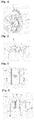
- Figures 1 and 2 are in respectively describing perspective view and cross-sectional perspective view of a vehicle wheel in accordance with present invention
- figure 3 is a top view of an air chamber bracket and a hole chamber bracket in accordance with present invention of a vehicle wheel, which describe composition of present invention as following;
- a vehicle wheel comprising;
- a wheel body(10) having four plate coupling portions(11);
- a vehicle wheel comprising; Plates(20) coupled respectively to the plate coupling portions(11);
- a ⁇ -shape Air chamber bracket(30) each having an Air chamber bracket hole(31) formed on an upper surface thereof and respectively coupled the upper surface of the plates(20);
- a hollow cylindrical Hole bracket(40) which is coupled through the Air chamber bracket hole(31) and moves up and down followed by rotation of the Wheel body(10);
- above parts comprise with an aluminium wheel body(10) and Plate(20) and synthetic resign Air chamber bracket providing an efficient injection molding.
- the present invention can reduce size of empty space between Wheel body(10) and the tire by Air chamber bracket(30), and minimize specific air pressure distribution by extending circulation of air between empty space above and Air chamber bracket(30) through Air chamber hole(31). Additionally, the present invention provides effect of improving strength of the wheel by Plate(20) and Air chamber bracket(30) combined with outer side of wheel body(10).
- Air chamber bracket(30) formed by injection molding can be combined through adhesive resin with Wheel body(10) without Plate(20).
- Figure 4 is cross-sectional diagram of an air chamber bracket and a hole chamber bracket A-A of a vehicle wheel in accordance with present invention and figures 5 a,b are respectively constitutional diagram of operating of a vehicle wheel of present invention in non-rotational/rotational state and detailed description is like following.
- a vehicle wheel comprising; A wheel body(10) having four plate coupling portions(11), Plates(20) coupled respectively to the plate coupling portions(11), A ⁇ -shape Air chamber bracket(30) each having an Air chamber bracket hole(31) formed on an upper surface thereof and respectively coupled the upper surface of the plates(20), an Air chamber brackets(30) providing Air chamber bracket spring settings(32) at upper side of inner side. and a hollow cylindrical Hole bracket(40) moves up and down providing Hole bracket spring settings(41) at its side, Spring(42) provided in the middle of Air chamber bracket spring settings(32) and Hole bracket spring settings(41).
- Air Chamber brackets(30) provides Hole bracket cap settings(33) at the upper side thereof and Hole bracket(40) couples with Hole bracket cap(43) at the end of its upper side. If Hole bracket cap(43) is metal or synthetic resins coming with bigger specific gravity compared to Hole bracket(40), Hole bracket(40) will effectively come out of Wheel body(10) by centrifugal force.
- Hollow cylindrical Hole bracket(40) normally stays within inside of Air chamber bracket(30) at low speed or stop state described as in figure 6-a , and comes out of Air chamber bracket(30) pat high speed as in figure 6-b .
- Air chamber bracket(30) comes with injection molding providing wide coverage of design availability. Therefore this will ease down forming air circulation path and partition described at Japan patent announcement No 05819340 figure 4 .
- Figure 6 is a side view of No 1 embodiment of a vehicle wheel present invention and figure is a side view of No 2 embodiment of a vehicle wheel present invention and detailed description is like following.
- a vehicle wheel comprising; Air chamber bracket hole(31) providing Air chamber bracket planar part(34) forming 90° angle of each Air chamber bracket hole(31) with respect to the center of the wheel and Air chamber bracket hole(31) providing air chamber bracket slope part(35) forming 90° angle of each Air chamber bracket hole(31) with respect to the center of the wheel. Also it is certainly possible to add multiple Air chamber bracket hole(31) to single Air chamber bracket(30). In additional, it is also possible to provide Air chamber bracket hole(31) to a point where centrifugal force due to rotation of Wheel(10) is the highest or where damage from impact is minimized.
Landscapes
- Engineering & Computer Science (AREA)
- Mechanical Engineering (AREA)
- Tires In General (AREA)
- Vehicle Body Suspensions (AREA)
- Body Structure For Vehicles (AREA)
Abstract
Description
- Following invention describe a vehicle wheel having synthetic resins air chamber providing hole bracket coupled with aluminum wheel so that it varies in proportional to rotational speed of wheel to reduce noise.
- Normally, a vehicle comprises structure which supports vehicle body by air filling derived by coupling inner sphere of tire with inner parts of rim provided at wheel. While driving vehicle, noise and vibration occur as tire continuously makes friction with road(surface).
- As the result, noise will give unpleasant feeling to the passenger, reducing ride comfort. Especially, noise will grow larger in high-speed traveling, so to reduce noise, various techniques are introduced such as adding absorbing material between wheel rim and tire or adding pattern on the rim. However, such techniques are lacking with durability and cannot efficiently reduce noise in accordance with rotation speed of wheel.
- Furthermore, Japan patent announcement No
05819340 - To resolve described problem above, following invention introduce a vehicle wheel comprising; the Air chamber brackets changing its form through injection, increasing freedom of design, and improving strength of wheel itself, and providing the variable Hole bracket in proportional with rotating speed of the wheel so that having effect of reducing noise.
- A vehicle wheel targeting above purpose comprises with; a wheel body having four plate coupling portions; plates coupled respectively to the plate coupling portions; plates coupled respectively to the plate coupling portions; air chamber brackets of a ∩-shape each having an air chamber bracket hole formed on an upper surface thereof and respectively coupled the upper surface of the plates; and a hollow cylindrical hole bracket which is coupled through the air chamber bracket hole and moves up and down with rotation of the wheel body.
- In more precisely, following invention comes with; a wheel body having four plate coupling portions and Plates coupled respectively to the plate coupling portions and a ∩-shape Air chamber bracket each having an Air chamber bracket hole formed on an upper surface thereof and respectively coupled the upper surface of the plates and A hollow cylindrical Hole bracket which is coupled through the Air chamber bracket hole and moves up and down followed by rotation of the Wheel body and an Air chamber brackets providing Air chamber bracket spring settings at upper side of inner side. and a Hole bracket providing Hole bracket spring settings at its side, Spring provided in the middle of Air chamber bracket spring settings and Hole bracket spring settings.
- Another feature of the invention comes with; a Hole bracket coupled with a Hole bracket cap at the end of its upper side, and an Air Chamber brackets providing Hole bracket cap settings at the upper side thereof.
- Another feature of the invention comes with; an Air chamber bracket hole providing Air chamber bracket planar part forming 90° angle of each Air chamber bracket hole with respect to the center of the wheel, and an Air chamber bracket hole providing air chamber bracket slope part forming 90° angle of each Air chamber bracket hole with respect to the center of the wheel.
- As described above, following invention introduce a vehicle wheel comprising; the Air chamber brackets changing its form through injection, increasing freedom of design, and improving strength of wheel itself, and providing the variable Hole bracket in proportional with rotating speed of the wheel so that having effect of reducing noise in eventually, providing stable impression of riding and minimizing displeasure of a passenger.
-
Figure 1 ; perspective view of a vehicle wheel in accordance with present invention. -
Figure 2 ; cross-sectional perspective view of a vehicle wheel in accordance with present invention. -
Figure 3 ; top view of an air chamber bracket and a hole chamber bracket in accordance with present invention of a vehicle wheel. -
Figure 4 ; cross-sectional diagram of an air chamber bracket and a hole chamber bracket A-A' of a vehicle wheel in accordance with present invention. -
Figures 5 a,b; constitutional diagram of operating of a vehicle wheel of present invention in non-rotational/rotational state. -
Figure 6 ; a side view of No 1 embodiment of a vehicle wheel present invention. -
Figure 7 ; a side view of No 2 embodiment of a vehicle wheel present invention. -
Figures 1 and 2 are in respectively describing perspective view and cross-sectional perspective view of a vehicle wheel in accordance with present invention, andfigure 3 is a top view of an air chamber bracket and a hole chamber bracket in accordance with present invention of a vehicle wheel, which describe composition of present invention as following;
A vehicle wheel comprising; A wheel body(10) having four plate coupling portions(11);
A vehicle wheel comprising; Plates(20) coupled respectively to the plate coupling portions(11); A ∩-shape Air chamber bracket(30) each having an Air chamber bracket hole(31) formed on an upper surface thereof and respectively coupled the upper surface of the plates(20); A hollow cylindrical Hole bracket(40) which is coupled through the Air chamber bracket hole(31) and moves up and down followed by rotation of the Wheel body(10);
In detail, above parts comprise with an aluminium wheel body(10) and Plate(20) and synthetic resign Air chamber bracket providing an efficient injection molding. Therefore, announced adhesion technology between metal and synthetic resign will be applied to Pate(20) and Air chamber bracket(30). Normally for driving vehicle, vibration and as such will be derived from sympathetic sound coming from 200∼250Hz frequency from hollow space between wheel tire and noise and vibration will become larger from specific air pressure distribution made form impact of surface foreign substance at the tire. - However, the present invention can reduce size of empty space between Wheel body(10) and the tire by Air chamber bracket(30), and minimize specific air pressure distribution by extending circulation of air between empty space above and Air chamber bracket(30) through Air chamber hole(31). Additionally, the present invention provides effect of improving strength of the wheel by Plate(20) and Air chamber bracket(30) combined with outer side of wheel body(10).
- Also, moving a hollow cylindrical Hole bracket(40) which moves up and down followed by rotation of the Wheel body(10) toward upper side in accordance with rotation speed of Wheel body(1), from which Hole bracket(40) stays within inside of Air chamber bracket(30) at low speed or stop state, and comes out of Air chamber bracket(30) at high speed changing air circulation path between space formed inside of Air chamber bracket(30) and Wheel bode(10) and tire so that minimizes noise induced from different frequency of low speed and high speed driving.
- The present invention provides structure; Hole bracket(40) extracts Air chamber bracket hole(31) by motor or as such which operates through elasticity of elastic material or acceleration sensor in relation with centrifugal force of rotating Wheel body(10) with Bottom side of Hole bracket(40) provided inside of Air chamber bracket(30) combining structure through elastic material or gear structure. Additional announced technology adopting changing length according to turning force or converting turning force to power can be used.
- And detailed method of combining Wheel body(10) and Plate(20) and Air chamber bracket(30) is like following;
First option introduce; plastic Air chamber bracket(30) formed by injection molding, which is combined through adhesive resin with aluminum Plate(20) and combine Plate(20) with Wheel body(10). - Second option introduce; over molding Air chamber bracket(30) to aluminum Plate(20) and combine them with Wheel body(10).
- Last option introduce; Air chamber bracket(30) formed by injection molding can be combined through adhesive resin with Wheel body(10) without Plate(20).
-
Figure 4 is cross-sectional diagram of an air chamber bracket and a hole chamber bracket A-A of a vehicle wheel in accordance with present invention andfigures 5 a,b are respectively constitutional diagram of operating of a vehicle wheel of present invention in non-rotational/rotational state and detailed description is like following. - A vehicle wheel comprising; A wheel body(10) having four plate coupling portions(11), Plates(20) coupled respectively to the plate coupling portions(11), A ∩-shape Air chamber bracket(30) each having an Air chamber bracket hole(31) formed on an upper surface thereof and respectively coupled the upper surface of the plates(20), an Air chamber brackets(30) providing Air chamber bracket spring settings(32) at upper side of inner side. and a hollow cylindrical Hole bracket(40) moves up and down providing Hole bracket spring settings(41) at its side, Spring(42) provided in the middle of Air chamber bracket spring settings(32) and Hole bracket spring settings(41). Also, Air Chamber brackets(30) provides Hole bracket cap settings(33) at the upper side thereof and Hole bracket(40) couples with Hole bracket cap(43) at the end of its upper side. If Hole bracket cap(43) is metal or synthetic resins coming with bigger specific gravity compared to Hole bracket(40), Hole bracket(40) will effectively come out of Wheel body(10) by centrifugal force.
- Above Hollow cylindrical Hole bracket(40) normally stays within inside of Air chamber bracket(30) at low speed or stop state described as in
figure 6-a , and comes out of Air chamber bracket(30) pat high speed as infigure 6-b . - This will eventually changes air circulation path between space formed inside of Air chamber bracket(30) and Wheel bode(10) and tire so that minimizes noise induced from different frequency of low speed and high speed driving.
- Also, Air chamber bracket(30) comes with injection molding providing wide coverage of design availability. Therefore this will ease down forming air circulation path and partition described at Japan patent announcement No
05819340 figure 4 . -
Figure 6 is a side view of No 1 embodiment of a vehicle wheel present invention and figure is a side view of No 2 embodiment of a vehicle wheel present invention and detailed description is like following. - A vehicle wheel comprising; Air chamber bracket hole(31) providing Air chamber bracket planar part(34) forming 90° angle of each Air chamber bracket hole(31) with respect to the center of the wheel and Air chamber bracket hole(31) providing air chamber bracket slope part(35) forming 90° angle of each Air chamber bracket hole(31) with respect to the center of the wheel. Also it is certainly possible to add multiple Air chamber bracket hole(31) to single Air chamber bracket(30). In additional, it is also possible to provide Air chamber bracket hole(31) to a point where centrifugal force due to rotation of Wheel(10) is the highest or where damage from impact is minimized.
- The present invention is described with figure of embodiment and examples, however a person of ordinary skill in the pertinent art will acknowledge that various remodeling and change can be within the boundary of idea and field of the invention.
- 10. Wheel body 11. Plate coupling portions
- 20.
Plate 30. Air chamber bracket - 31. Air chamber bracket hole 32. Air chamber bracket spring settings
- 33. Hole bracket cap settings 34. Air chamber bracket planar part
- 35. air chamber bracket slope part 40. Hole bracket
- 41. Hole bracket spring settings 42. Spring
- 43. Hole bracket cap
Claims (7)
- A vehicle wheel comprising;
A wheel body(10) having four plate coupling portions(11);
Plates(20) coupled respectively to the plate coupling portions(11);
A ∩-shape Air chamber bracket(30) each having an Air chamber bracket hole(31) formed on an upper surface thereof and respectively coupled the upper surface of the plates(20);
A hollow cylindrical Hole bracket(40) which is coupled through the Air chamber bracket hole(31) and moves up and down followed by rotation of the Wheel body(10); - According to Claim 1
A vehicle wheel featuring Hole bracket(40) moving upper side in proportional with moving speed of Wheel body(10); - According to Claim 1
A vehicle wheel comprising; an Air chamber brackets(30) providing Air chamber bracket spring settings(32) at upper side of inner side. and a Hole bracket(40) providing Hole bracket spring settings41) at its side, Spring(42) provided in the middle of Air chamber bracket spring settings(32) and Hole bracket spring settings(41); - According to Claim 3
A vehicle wheel comprising; Air Chamber brackets(30) providing Hole bracket cap settings(33) at the upper side thereof; - According to Claim 3
A vehicle wheel comprising; Hole bracket(40) coupled with Hole bracket cap(43) at the end of its upper side; - According to Claim 1 and 3
A vehicle wheel comprising; Air chamber bracket hole(31) providing Air chamber bracket planar part(34) forming 90° angle of each Air chamber bracket hole(31) with respect to the center of the wheel. - According to Claim 1 and 3
A vehicle wheel comprising; Air chamber bracket hole(31) providing air chamber bracket slope part(35) forming 90° angle of each Air chamber bracket hole(31) with respect to the center of the wheel.
Applications Claiming Priority (2)
| Application Number | Priority Date | Filing Date | Title |
|---|---|---|---|
| KR1020160052895A KR101828315B1 (en) | 2016-04-29 | 2016-04-29 | Vehicular Wheel |
| PCT/KR2017/004489 WO2017188751A1 (en) | 2016-04-29 | 2017-04-27 | Vehicle wheel |
Publications (2)
| Publication Number | Publication Date |
|---|---|
| EP3450199A1 true EP3450199A1 (en) | 2019-03-06 |
| EP3450199A4 EP3450199A4 (en) | 2020-01-15 |
Family
ID=60160958
Family Applications (1)
| Application Number | Title | Priority Date | Filing Date |
|---|---|---|---|
| EP17789935.8A Withdrawn EP3450199A4 (en) | 2016-04-29 | 2017-04-27 | Vehicle wheel |
Country Status (6)
| Country | Link |
|---|---|
| US (1) | US20190070895A1 (en) |
| EP (1) | EP3450199A4 (en) |
| JP (1) | JP2019514791A (en) |
| KR (1) | KR101828315B1 (en) |
| CN (1) | CN109414957A (en) |
| WO (1) | WO2017188751A1 (en) |
Cited By (1)
| Publication number | Priority date | Publication date | Assignee | Title |
|---|---|---|---|---|
| US20200009905A1 (en) * | 2018-07-09 | 2020-01-09 | Honda Motor Co., Ltd. | Vehicle wheel |
Families Citing this family (5)
| Publication number | Priority date | Publication date | Assignee | Title |
|---|---|---|---|---|
| KR102097003B1 (en) * | 2018-08-29 | 2020-04-03 | 주식회사 팔 | Resonance Wheel adapted to tire inner temperature change |
| KR102153933B1 (en) * | 2018-11-30 | 2020-09-10 | 엠에이치기술개발 주식회사 | Wheel assembly |
| KR102552509B1 (en) * | 2018-12-03 | 2023-07-06 | 현대자동차주식회사 | Tyre noise reduction device |
| KR102664117B1 (en) * | 2019-06-05 | 2024-05-10 | 현대자동차주식회사 | Vehicle wheel with resonator |
| KR102202872B1 (en) * | 2020-08-13 | 2021-01-15 | 엠에이치기술개발 주식회사 | Wheel assembly |
Family Cites Families (17)
| Publication number | Priority date | Publication date | Assignee | Title |
|---|---|---|---|---|
| DE4402699C2 (en) * | 1994-01-29 | 1996-01-11 | Continental Ag | Device for reducing tire / road noise |
| KR200173037Y1 (en) * | 1994-12-30 | 2000-05-01 | 정몽규 | Pneumatic Feed Wheel |
| US5891278A (en) * | 1997-01-07 | 1999-04-06 | Rivin; Evgeny I. | Pneumatic wheels |
| AU7785200A (en) * | 1999-09-29 | 2001-04-30 | Michelin Recherche Et Technique S.A. | Safety support with noise suppressor for vehicle wheel |
| JP2001180216A (en) * | 1999-12-22 | 2001-07-03 | Sumitomo Rubber Ind Ltd | Assembly of pneumatic tire and rim |
| JP2004306653A (en) * | 2003-04-02 | 2004-11-04 | Honda Motor Co Ltd | Vehicle wheels |
| EP1912804B1 (en) * | 2005-06-24 | 2013-09-25 | Tire Acoustics, LLC | Tire and wheel noise reducing device and system |
| JP4520971B2 (en) * | 2006-11-14 | 2010-08-11 | 本田技研工業株式会社 | Vehicle wheel and method of manufacturing vehicle wheel |
| US20080179939A1 (en) * | 2007-01-25 | 2008-07-31 | Asahi Tec Corporation | Vehicle wheel and manufacturing method of the same |
| JP2008183930A (en) * | 2007-01-26 | 2008-08-14 | Asahi Tec Corp | Wheel for vehicle, and its manufacturing method |
| KR100884194B1 (en) * | 2007-09-17 | 2009-02-18 | 금호타이어 주식회사 | Tire puncture preparation device and pneumatic tire provided with the device |
| JP4460593B2 (en) * | 2007-09-19 | 2010-05-12 | 本田技研工業株式会社 | Vehicle wheel |
| KR101218834B1 (en) * | 2010-09-29 | 2013-01-07 | 주식회사 만도 | Body amplitude sensitive air spring |
| US8820376B2 (en) * | 2011-08-05 | 2014-09-02 | The Goodyear Tire & Rubber Company | Diaphragm pump for self-inflating tire |
| US9090128B2 (en) * | 2013-08-16 | 2015-07-28 | GM Global Technology Operations LLC | Wheel assembly for a vehicle and a method of manufacturing the wheel assembly |
| CN203995450U (en) * | 2014-07-31 | 2014-12-10 | 重庆长安汽车股份有限公司 | A kind of denoising structure of motor tire |
| KR101822273B1 (en) * | 2016-04-18 | 2018-03-09 | 현대자동차주식회사 | Apparatus for noise diminution of tire |
-
2016
- 2016-04-29 KR KR1020160052895A patent/KR101828315B1/en not_active Expired - Fee Related
-
2017
- 2017-04-27 JP JP2019509450A patent/JP2019514791A/en active Pending
- 2017-04-27 CN CN201780031891.9A patent/CN109414957A/en active Pending
- 2017-04-27 EP EP17789935.8A patent/EP3450199A4/en not_active Withdrawn
- 2017-04-27 WO PCT/KR2017/004489 patent/WO2017188751A1/en not_active Ceased
-
2018
- 2018-10-29 US US16/173,522 patent/US20190070895A1/en not_active Abandoned
Cited By (1)
| Publication number | Priority date | Publication date | Assignee | Title |
|---|---|---|---|---|
| US20200009905A1 (en) * | 2018-07-09 | 2020-01-09 | Honda Motor Co., Ltd. | Vehicle wheel |
Also Published As
| Publication number | Publication date |
|---|---|
| KR20170123463A (en) | 2017-11-08 |
| EP3450199A4 (en) | 2020-01-15 |
| WO2017188751A1 (en) | 2017-11-02 |
| US20190070895A1 (en) | 2019-03-07 |
| CN109414957A (en) | 2019-03-01 |
| JP2019514791A (en) | 2019-06-06 |
| KR101828315B1 (en) | 2018-02-12 |
Similar Documents
| Publication | Publication Date | Title |
|---|---|---|
| EP3450199A1 (en) | Vehicle wheel | |
| JP6493864B2 (en) | Non pneumatic tire | |
| EP2162345B1 (en) | Handlebar with elastic hinges | |
| JP2018016303A (en) | Non pneumatic tire | |
| JP2016522771A (en) | Independent wheel suspension for vehicle having spring steering structure formed in fiber reinforced material | |
| CN102398634A (en) | Rectifying device | |
| US20130187320A1 (en) | Shock absorption mount having a housing with a contoured inner surface | |
| JP2016070501A (en) | Suspension bearing device, automobile equipped with the suspension bearing device, and manufacturing method | |
| JP2017165119A (en) | Airless tire and device and method for manufacturing the same | |
| JP2008030648A5 (en) | ||
| HUE026878T2 (en) | Gear, in particular for a motor vehicle actuator | |
| CN103568704B (en) | Vehicle rim | |
| WO2014097864A1 (en) | Fuel tank shock-absorbing member | |
| US20190111731A1 (en) | Vehicle wheel | |
| JPS642544B2 (en) | ||
| US7901012B1 (en) | Wheel which produces an eccentric visual effect | |
| JP2004306935A (en) | Under-floor flow straightening structure of automobile | |
| KR101878040B1 (en) | Mounting bush and manufacturing method thereof | |
| JP6965055B2 (en) | Non-pneumatic tires | |
| CN210211898U (en) | Wheel hub assembly and electric vehicle having the same | |
| KR20190054642A (en) | Tire with reinforced apex | |
| JP7385472B2 (en) | Fiber-reinforced resin wheels and vehicles equipped with them | |
| CN212386231U (en) | Spiral hub | |
| KR101135964B1 (en) | Interior materials for airless tire and tire equipped therewith | |
| JP6633169B2 (en) | Air spring and squeeze control member |
Legal Events
| Date | Code | Title | Description |
|---|---|---|---|
| STAA | Information on the status of an ep patent application or granted ep patent |
Free format text: STATUS: THE INTERNATIONAL PUBLICATION HAS BEEN MADE |
|
| PUAI | Public reference made under article 153(3) epc to a published international application that has entered the european phase |
Free format text: ORIGINAL CODE: 0009012 |
|
| STAA | Information on the status of an ep patent application or granted ep patent |
Free format text: STATUS: REQUEST FOR EXAMINATION WAS MADE |
|
| 17P | Request for examination filed |
Effective date: 20181128 |
|
| AK | Designated contracting states |
Kind code of ref document: A1 Designated state(s): AL AT BE BG CH CY CZ DE DK EE ES FI FR GB GR HR HU IE IS IT LI LT LU LV MC MK MT NL NO PL PT RO RS SE SI SK SM TR |
|
| AX | Request for extension of the european patent |
Extension state: BA ME |
|
| DAV | Request for validation of the european patent (deleted) | ||
| DAX | Request for extension of the european patent (deleted) | ||
| A4 | Supplementary search report drawn up and despatched |
Effective date: 20191217 |
|
| RIC1 | Information provided on ipc code assigned before grant |
Ipc: B60C 19/00 20060101ALI20191211BHEP Ipc: B60B 21/12 20060101AFI20191211BHEP Ipc: B60B 25/00 20060101ALI20191211BHEP |
|
| STAA | Information on the status of an ep patent application or granted ep patent |
Free format text: STATUS: THE APPLICATION IS DEEMED TO BE WITHDRAWN |
|
| 18D | Application deemed to be withdrawn |
Effective date: 20200721 |