WO2014097864A1 - Fuel tank shock-absorbing member - Google Patents
Fuel tank shock-absorbing member Download PDFInfo
- Publication number
- WO2014097864A1 WO2014097864A1 PCT/JP2013/082263 JP2013082263W WO2014097864A1 WO 2014097864 A1 WO2014097864 A1 WO 2014097864A1 JP 2013082263 W JP2013082263 W JP 2013082263W WO 2014097864 A1 WO2014097864 A1 WO 2014097864A1
- Authority
- WO
- WIPO (PCT)
- Prior art keywords
- fuel tank
- buffer member
- recess
- main body
- engaging portion
- Prior art date
Links
- 239000002828 fuel tank Substances 0.000 title claims abstract description 48
- 230000002093 peripheral effect Effects 0.000 claims abstract description 11
- 239000006096 absorbing agent Substances 0.000 claims 1
- 230000035939 shock Effects 0.000 claims 1
- 230000015572 biosynthetic process Effects 0.000 abstract 1
- 239000000446 fuel Substances 0.000 description 3
- 238000009423 ventilation Methods 0.000 description 3
- 238000005452 bending Methods 0.000 description 2
- 238000000034 method Methods 0.000 description 2
- 210000003813 thumb Anatomy 0.000 description 2
- 239000000853 adhesive Substances 0.000 description 1
- 230000001070 adhesive effect Effects 0.000 description 1
- 238000005273 aeration Methods 0.000 description 1
- 230000007423 decrease Effects 0.000 description 1
- 230000001771 impaired effect Effects 0.000 description 1
- 239000000463 material Substances 0.000 description 1
- 235000013372 meat Nutrition 0.000 description 1
- 239000002184 metal Substances 0.000 description 1
- 238000000465 moulding Methods 0.000 description 1
- 239000011347 resin Substances 0.000 description 1
- 229920005989 resin Polymers 0.000 description 1
- 238000010008 shearing Methods 0.000 description 1
- 238000009751 slip forming Methods 0.000 description 1
- 239000013585 weight reducing agent Substances 0.000 description 1
Images

Classifications
-
- F—MECHANICAL ENGINEERING; LIGHTING; HEATING; WEAPONS; BLASTING
- F16—ENGINEERING ELEMENTS AND UNITS; GENERAL MEASURES FOR PRODUCING AND MAINTAINING EFFECTIVE FUNCTIONING OF MACHINES OR INSTALLATIONS; THERMAL INSULATION IN GENERAL
- F16F—SPRINGS; SHOCK-ABSORBERS; MEANS FOR DAMPING VIBRATION
- F16F15/00—Suppression of vibrations in systems; Means or arrangements for avoiding or reducing out-of-balance forces, e.g. due to motion
- F16F15/02—Suppression of vibrations of non-rotating, e.g. reciprocating systems; Suppression of vibrations of rotating systems by use of members not moving with the rotating systems
- F16F15/04—Suppression of vibrations of non-rotating, e.g. reciprocating systems; Suppression of vibrations of rotating systems by use of members not moving with the rotating systems using elastic means
- F16F15/08—Suppression of vibrations of non-rotating, e.g. reciprocating systems; Suppression of vibrations of rotating systems by use of members not moving with the rotating systems using elastic means with rubber springs ; with springs made of rubber and metal
-
- B—PERFORMING OPERATIONS; TRANSPORTING
- B60—VEHICLES IN GENERAL
- B60K—ARRANGEMENT OR MOUNTING OF PROPULSION UNITS OR OF TRANSMISSIONS IN VEHICLES; ARRANGEMENT OR MOUNTING OF PLURAL DIVERSE PRIME-MOVERS IN VEHICLES; AUXILIARY DRIVES FOR VEHICLES; INSTRUMENTATION OR DASHBOARDS FOR VEHICLES; ARRANGEMENTS IN CONNECTION WITH COOLING, AIR INTAKE, GAS EXHAUST OR FUEL SUPPLY OF PROPULSION UNITS IN VEHICLES
- B60K15/00—Arrangement in connection with fuel supply of combustion engines or other fuel consuming energy converters, e.g. fuel cells; Mounting or construction of fuel tanks
- B60K15/03—Fuel tanks
- B60K15/063—Arrangement of tanks
- B60K15/067—Mounting of tanks
-
- F—MECHANICAL ENGINEERING; LIGHTING; HEATING; WEAPONS; BLASTING
- F16—ENGINEERING ELEMENTS AND UNITS; GENERAL MEASURES FOR PRODUCING AND MAINTAINING EFFECTIVE FUNCTIONING OF MACHINES OR INSTALLATIONS; THERMAL INSULATION IN GENERAL
- F16B—DEVICES FOR FASTENING OR SECURING CONSTRUCTIONAL ELEMENTS OR MACHINE PARTS TOGETHER, e.g. NAILS, BOLTS, CIRCLIPS, CLAMPS, CLIPS OR WEDGES; JOINTS OR JOINTING
- F16B21/00—Means for preventing relative axial movement of a pin, spigot, shaft or the like and a member surrounding it; Stud-and-socket releasable fastenings
- F16B21/06—Releasable fastening devices with snap-action
- F16B21/08—Releasable fastening devices with snap-action in which the stud, pin, or spigot has a resilient part
- F16B21/086—Releasable fastening devices with snap-action in which the stud, pin, or spigot has a resilient part the shank of the stud, pin or spigot having elevations, ribs, fins or prongs intended for deformation or tilting predominantly in a direction perpendicular to the direction of insertion
-
- F—MECHANICAL ENGINEERING; LIGHTING; HEATING; WEAPONS; BLASTING
- F16—ENGINEERING ELEMENTS AND UNITS; GENERAL MEASURES FOR PRODUCING AND MAINTAINING EFFECTIVE FUNCTIONING OF MACHINES OR INSTALLATIONS; THERMAL INSULATION IN GENERAL
- F16F—SPRINGS; SHOCK-ABSORBERS; MEANS FOR DAMPING VIBRATION
- F16F1/00—Springs
- F16F1/36—Springs made of rubber or other material having high internal friction, e.g. thermoplastic elastomers
- F16F1/373—Springs made of rubber or other material having high internal friction, e.g. thermoplastic elastomers characterised by having a particular shape
- F16F1/377—Springs made of rubber or other material having high internal friction, e.g. thermoplastic elastomers characterised by having a particular shape having holes or openings
-
- B—PERFORMING OPERATIONS; TRANSPORTING
- B60—VEHICLES IN GENERAL
- B60K—ARRANGEMENT OR MOUNTING OF PROPULSION UNITS OR OF TRANSMISSIONS IN VEHICLES; ARRANGEMENT OR MOUNTING OF PLURAL DIVERSE PRIME-MOVERS IN VEHICLES; AUXILIARY DRIVES FOR VEHICLES; INSTRUMENTATION OR DASHBOARDS FOR VEHICLES; ARRANGEMENTS IN CONNECTION WITH COOLING, AIR INTAKE, GAS EXHAUST OR FUEL SUPPLY OF PROPULSION UNITS IN VEHICLES
- B60K15/00—Arrangement in connection with fuel supply of combustion engines or other fuel consuming energy converters, e.g. fuel cells; Mounting or construction of fuel tanks
- B60K15/03—Fuel tanks
- B60K15/063—Arrangement of tanks
- B60K2015/0634—Arrangement of tanks the fuel tank is arranged below the vehicle floor
-
- B—PERFORMING OPERATIONS; TRANSPORTING
- B60—VEHICLES IN GENERAL
- B60Y—INDEXING SCHEME RELATING TO ASPECTS CROSS-CUTTING VEHICLE TECHNOLOGY
- B60Y2306/00—Other features of vehicle sub-units
- B60Y2306/09—Reducing noise
-
- B—PERFORMING OPERATIONS; TRANSPORTING
- B60—VEHICLES IN GENERAL
- B60Y—INDEXING SCHEME RELATING TO ASPECTS CROSS-CUTTING VEHICLE TECHNOLOGY
- B60Y2400/00—Special features of vehicle units
- B60Y2400/48—Vibration dampers, e.g. dual mass flywheels
Definitions
- the present invention relates to a buffer member for a fuel tank interposed between a fuel tank and a vehicle body.
- Patent Document 1 a technique is known in which a buffer member such as rubber is interposed between a fuel tank for a vehicle and a floor panel of a vehicle body.
- a buffer member such as rubber is interposed between a fuel tank for a vehicle and a floor panel of a vehicle body.
- the conventional cushioning member is attached to the fuel tank via an adhesive, there is a problem that the adhesion holding property and the pasting workability are poor.
- the buffer member can be assembled with one touch by pushing the buffer member into the recess of the fuel tank.
- the edge portion of the engaging portion is easily deformed, and the buffer member may be detached from the recess.
- the cushioning member is assembled to the recess, if the airtightness between the recess and the engaging portion is high, there is a problem that it is difficult to assemble the cushioning member because the air in the recess does not escape to the outside.
- the present invention was created to solve such problems, and an object of the present invention is to provide a fuel tank cushioning member that is easy to assemble and that is not easily detached from the fuel tank.
- the present invention provides a fuel tank buffer member attached to a recess of a fuel tank, the main body portion, a shaft portion depending from the main body portion, and the shaft portion at the tip of the shaft portion. And an engaging portion that engages with the recess, and a plurality of radially extending ribs are formed on the outer peripheral surface of the engaging portion.
- the plurality of ribs are formed on the outer peripheral surface of the engaging portion, deformation of the engaging portion can be suppressed. Thereby, it becomes difficult to remove the buffer member for the fuel tank from the recess. Moreover, since the space between the adjacent ribs serves as a vent hole, the air in the recesses can easily escape to the outside during assembly. Thereby, the assembling property of the buffer member for the fuel tank is improved.
- the engaging portion has an end surface perpendicular to the shaft portion, and one end side of the rib is continuously formed from the end surface. According to such a configuration, it is possible to reliably reinforce a portion that is easily deformed.
- a hollow portion is formed in the axial direction. According to this configuration, it is possible to reduce the weight of the buffer member.
- the fuel tank buffer member according to the present invention is easy to assemble and difficult to come off from the fuel tank.
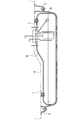
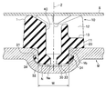
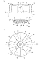
- FIG. 1 is an overall side sectional view of a fuel tank and a fuel tank buffer member according to an embodiment of the present invention. It is a sectional side view which shows the attachment state of the buffer member for fuel tanks concerning this embodiment. It is a perspective view of the buffer member for fuel tanks concerning this embodiment. It is a figure which shows the buffer member for fuel tanks concerning this embodiment, Comprising: (a) is a side view, (b) is a top view.
- the fuel tank buffer member 1 (hereinafter also referred to as “buffer member 1”) according to the present embodiment is a cushion member interposed between the fuel tank M and the vehicle body S.
- the fuel tank M is a hollow container made of resin or metal for storing fuel, and is fixed to the bottom of the vehicle body (floor panel) S.
- the bottom of the fuel tank M is supported by a tank band B having a substantially U shape in cross section, and both ends of the tank band B are fixed to the vehicle body S via brackets C and C.
- the recess N is a recess in which the buffer member 1 is engaged.
- the recess N is formed on the surface of the fuel tank M that faces the vehicle body S.
- the recess N has a bottom Na that is rounded out and a plurality of protrusions Nb that protrude toward the center of the opening at the opening of the recess N.
- the number of protrusions Nb is not particularly limited, but in the present embodiment, three protrusions Nb are formed at equal intervals in the circumferential direction.
- the protruding portion Nb is divided into a plurality of parts, but may be formed of a single continuous portion.
- the buffer member 1 is a member interposed between the fuel tank M and the vehicle body S as shown in FIGS.
- the buffer member 1 is made of rubber and is integrally formed.
- the buffer member 1 is a member for avoiding a collision between the fuel tank M and the vehicle body S and for preventing vibrations and noise due to the ripple of fuel in the fuel tank from being transmitted to the vehicle body.
- the material of the buffer member 1 and the molding method are not particularly limited.
- the buffer member 1 may be composed of a plurality of members.
- the shock-absorbing member 1 includes a main body part 10, a shaft part 20, and an engaging part 30.
- the main body 10 is a part exposed to the outside of the fuel tank M.
- the main body 10 includes a base 11, a plurality of peaks 12 formed on the base 11, and a plurality of valleys 13 formed on the base 11.
- the base 11 has a ring shape.
- the mountain portion 12 is formed on the base portion 11 and has a substantially triangular prism shape in plan view.
- the number of the ridges 12 is not particularly limited, in the present embodiment, five ridges 12 are formed at equal intervals in the circumferential direction.
- the valley 13 is a recess formed between the peaks 12 and 12. The number of valleys 13 is not particularly limited, but is five in this embodiment.
- the shaft portion 20 is a portion depending from the main body portion 10 and has a cylindrical shape. As shown in FIG. 2, the shaft portion 20 is smaller than the outer diameter of the main body 10 at the center of the main body 10 and slightly smaller than the inner diameter W of the opening of the recess N. The length of the shaft portion 20 is smaller than the plate thickness of the fuel tank M.
- the engaging portion 30 is a portion that engages with the recess N.
- the engaging portion 30 is formed so that the proximal end side is larger than the outer diameter of the shaft portion 20 and is reduced in diameter toward the distal end side.
- the engaging portion 30 is composed of an upper end surface 31, an outer peripheral surface 32, and a lower end surface 33.
- the upper end surface 31 is a plane perpendicular to the shaft portion 20.
- the outer peripheral surface 32 is configured by a curved surface that decreases in diameter as the distance from the upper end surface 31 increases.
- the lower end surface 33 is parallel to the upper end surface 31.
- a plurality of ribs 34 are formed on the outer circumferential surface 32 at equal intervals in the circumferential direction.
- the ribs 34 are protrusions that extend radially on the outer peripheral surface 32 in plan view. More specifically, one end of the rib 34 continues to the upper end surface 31, and the other end extends to the vicinity of the lower end surface 33.
- the shape of the rib 34 is not particularly limited, but in the present embodiment, the base end side is the widest and becomes narrower as the distance from the engaging portion 30 increases.
- the rib 34 may be formed away from the upper end surface 31.
- the shock-absorbing member 1 has a hollow portion 40 formed in parallel with the axis Z.
- the hollow portion 40 penetrates in the axial direction in the present embodiment.
- the engaging portion 30 when the buffer member 1 is assembled to the fuel tank M, the engaging portion 30 may be inserted into the concave portion N of the fuel tank M when the operator pushes the upper end surface of the main body portion 10. As a result, the engaging portion 30 enters the recess N, and the lower end surface of the main body portion 10 comes into contact with the surface of the fuel tank M or is disposed with a fine gap. Since the engaging portion 30 has an outer diameter larger than the inner diameter W of the opening of the recess N, it is difficult for the engaging portion 30 to be detached from the fuel tank M.
- the buffer member 1 since the plurality of ribs 34 are formed on the outer peripheral surface 32 of the engaging portion 30, the edge portion of the engaging portion 30 is not easily deformed. Thereby, the buffer member 1 is less likely to be detached from the recess N. More specifically, when an upward force is applied to the buffer member 1 in a state where the buffer member 1 is engaged with the recess N, the edge of the engagement portion 30 turns outward (the apex in FIG. 4A). A bending moment acts in the direction of arrow P at 30a. However, in the present embodiment, since the ribs 34 extending radially are formed on the outer peripheral surface 32, deformation can be prevented against the bending moment.
- the position of the rib 34 is not particularly limited as long as it is the outer peripheral surface 32.
- the rib 34 continuously from the upper end surface 31 as in the present embodiment, the periphery of the most deformable vertex 30a of the engaging portion 30 is assured. Can be reinforced.
- the friction between the concave portion N and the engaging portion 30 when the buffer member 1 is assembled can be reduced, so that it can be pushed in smoothly.
- the space between the adjacent ribs 34 serves as a vent hole, so that the air in the recess N can easily escape to the outside. Thereby, the assembly
- the buffer member 1 can be reduced in weight. Further, since the meat near the axis Z is eliminated, the buffer member 1 is easily bent. Thereby, assembly
- the vertical cross section passing through the axis Z has a combination of peaks and peaks or a combination of valleys and valleys.
- the shapes of the vertical cross sections are different, and the degree of deformation is also unbalanced.
- the plurality of vertical sections passing through the axis Z have the same shape by making the ridges 12 and the valleys 13 odd, respectively, a shearing force is applied. The deformation of is almost equivalent.
Landscapes
- Engineering & Computer Science (AREA)
- General Engineering & Computer Science (AREA)
- Mechanical Engineering (AREA)
- Combustion & Propulsion (AREA)
- Chemical & Material Sciences (AREA)
- Transportation (AREA)
- Life Sciences & Earth Sciences (AREA)
- Sustainable Energy (AREA)
- Sustainable Development (AREA)
- Physics & Mathematics (AREA)
- Acoustics & Sound (AREA)
- Aviation & Aerospace Engineering (AREA)
- Cooling, Air Intake And Gas Exhaust, And Fuel Tank Arrangements In Propulsion Units (AREA)
- Vibration Dampers (AREA)
- Springs (AREA)
Abstract
Provided is a fuel tank shock-absorbing member that is easily assembled and that does not easily separate from a fuel tank. A fuel tank shock-absorbing member (1) attached to a concave part (N) of a fuel tank (M) is characterized in comprising a main body part (10), a shaft part (20) hanging down from the main body part (10), and an engaging part (30) formed having a greater diameter than the shaft part (20) at the tip of the shaft part (20) and engaged with the concave part (N); a plurality of ribs (34) extending in a radial formation being formed in an outer peripheral surface (32) of the engaging part (30).
Description
本発明は、燃料タンクと車体との間に介設される燃料タンク用緩衝部材に関する。
The present invention relates to a buffer member for a fuel tank interposed between a fuel tank and a vehicle body.
例えば、特許文献1に示すように、車両用の燃料タンクと車体のフロアパネルとの間にゴムなどの緩衝部材を介設する技術が知られている。燃料タンクとフロアパネルとの間に緩衝部材を設けることで、燃料タンクとフロアパネルとの衝突を防ぐとともに、燃料タンク内の燃料の波立ち等による振動や騒音が車体に伝達するのを防止できる。
For example, as shown in Patent Document 1, a technique is known in which a buffer member such as rubber is interposed between a fuel tank for a vehicle and a floor panel of a vehicle body. By providing the buffer member between the fuel tank and the floor panel, it is possible to prevent the fuel tank and the floor panel from colliding with each other, and to prevent the vibration and noise caused by the ripple of fuel in the fuel tank from being transmitted to the vehicle body.
ところが、従来の緩衝部材は、燃料タンクに接着剤を介して取り付けるため、接着保持性及び貼付作業性が悪いという問題があった。そこで、例えば、燃料タンクに凹部を設けつつ、緩衝部材の先端側に前記凹部と係合する係合部を設けることが考えられる。このような緩衝部材によれば、燃料タンクの凹部に緩衝部材を押し込むことで、ワンタッチで組み付けることができる。
However, since the conventional cushioning member is attached to the fuel tank via an adhesive, there is a problem that the adhesion holding property and the pasting workability are poor. Thus, for example, it is conceivable to provide an engagement portion that engages with the recess on the tip side of the buffer member while providing a recess in the fuel tank. According to such a buffer member, the buffer member can be assembled with one touch by pushing the buffer member into the recess of the fuel tank.
しかし、前記した緩衝部材では、係合部と凹部とが係合する際に、係合部の縁部が変形しやすくなり、緩衝部材が凹部から外れてしまうおそれがある。また、緩衝部材を凹部に組み付ける際に、凹部と係合部との気密性が高いと凹部内の空気が外部に抜けないため緩衝部材を組み付けづらいという問題がある。
However, in the buffer member described above, when the engaging portion and the recess are engaged, the edge portion of the engaging portion is easily deformed, and the buffer member may be detached from the recess. Further, when the cushioning member is assembled to the recess, if the airtightness between the recess and the engaging portion is high, there is a problem that it is difficult to assemble the cushioning member because the air in the recess does not escape to the outside.
本発明はこのような課題を解決するために創作されたものであり、組み付けが容易であるとともに燃料タンクから外れにくい燃料タンク用緩衝部材を提供することを目的とする。
The present invention was created to solve such problems, and an object of the present invention is to provide a fuel tank cushioning member that is easy to assemble and that is not easily detached from the fuel tank.
本発明は、前記課題を解決するため、燃料タンクの凹部に取り付けられる燃料タンク用緩衝部材であって、本体部と、前記本体部から垂下する軸部と、前記軸部の先端に前記軸部よりも拡径して形成され前記凹部と係合する係合部と、を有し、前記係合部の外周面には、放射状に延設された複数のリブが形成されていることを特徴とする。
In order to solve the above-described problem, the present invention provides a fuel tank buffer member attached to a recess of a fuel tank, the main body portion, a shaft portion depending from the main body portion, and the shaft portion at the tip of the shaft portion. And an engaging portion that engages with the recess, and a plurality of radially extending ribs are formed on the outer peripheral surface of the engaging portion. And
かかる構成によれば、係合部の外周面に複数のリブが形成されているため、係合部の変形を抑制できる。これにより、燃料タンク用緩衝部材が凹部から外れにくくなる。また、隣り合うリブの間が通気口となるため、組み付け時に凹部内の空気が外部に抜けやすくなる。これにより、燃料タンク用緩衝部材の組み付け性が向上する。
According to such a configuration, since the plurality of ribs are formed on the outer peripheral surface of the engaging portion, deformation of the engaging portion can be suppressed. Thereby, it becomes difficult to remove the buffer member for the fuel tank from the recess. Moreover, since the space between the adjacent ribs serves as a vent hole, the air in the recesses can easily escape to the outside during assembly. Thereby, the assembling property of the buffer member for the fuel tank is improved.
また、前記係合部は、前記軸部に対して垂直な端面を備え、前記リブの一端側は前記端面から連続して形成されていることが好ましい。かかる構成によれば、変形しやすい部位を確実に補強することができる。
Further, it is preferable that the engaging portion has an end surface perpendicular to the shaft portion, and one end side of the rib is continuously formed from the end surface. According to such a configuration, it is possible to reliably reinforce a portion that is easily deformed.
また、軸方向に中空部が形成されていることが好ましい。かかる構成によれば、緩衝部材の軽量化を図ることができる。
Further, it is preferable that a hollow portion is formed in the axial direction. According to this configuration, it is possible to reduce the weight of the buffer member.
本発明に係る燃料タンク用緩衝部材によれば、組み付けが容易であるとともに燃料タンクから外れにくい。
The fuel tank buffer member according to the present invention is easy to assemble and difficult to come off from the fuel tank.
本発明の実施形態について図面を参照して詳細に説明する。図1に示すように、本実施形態に係る燃料タンク用緩衝部材1(以下、「緩衝部材1」とも言う)は、燃料タンクMと車体Sの間に介設されるクッション部材である。
Embodiments of the present invention will be described in detail with reference to the drawings. As shown in FIG. 1, the fuel tank buffer member 1 (hereinafter also referred to as “buffer member 1”) according to the present embodiment is a cushion member interposed between the fuel tank M and the vehicle body S.
燃料タンクMは、燃料を貯留するための樹脂製又は金属製の中空容器であって、車体(フロアパネル)Sの底に固定されている。本実施形態では、燃料タンクMの底部が断面視略U字状を呈するタンクバンドBで支持されており、ブラケットC,Cを介してタンクバンドBの両端が車体Sに固定されている。
The fuel tank M is a hollow container made of resin or metal for storing fuel, and is fixed to the bottom of the vehicle body (floor panel) S. In the present embodiment, the bottom of the fuel tank M is supported by a tank band B having a substantially U shape in cross section, and both ends of the tank band B are fixed to the vehicle body S via brackets C and C.
燃料タンクMの表面には、図2に示すように、凹部Nが形成されている。凹部Nは、緩衝部材1が係合する窪みである。凹部Nは、本実施形態では、燃料タンクMの車体Sと対向する面に形成されている。凹部Nは、丸く繰り抜かれた底部Naと、凹部Nの開口部において開口部の中心に向けて突出する複数の突起部Nbとを有する。突起部Nbの個数は特に制限されないが、本実施形態では周方向に等間隔に3つ形成されている。突起部Nbは、本実施形態では複数個に分割して構成しているが、連続する単一の部位で構成してもよい。
On the surface of the fuel tank M, a recess N is formed as shown in FIG. The recess N is a recess in which the buffer member 1 is engaged. In this embodiment, the recess N is formed on the surface of the fuel tank M that faces the vehicle body S. The recess N has a bottom Na that is rounded out and a plurality of protrusions Nb that protrude toward the center of the opening at the opening of the recess N. The number of protrusions Nb is not particularly limited, but in the present embodiment, three protrusions Nb are formed at equal intervals in the circumferential direction. In the present embodiment, the protruding portion Nb is divided into a plurality of parts, but may be formed of a single continuous portion.
緩衝部材1は、図2及び図3に示すように、燃料タンクMと車体Sとの間に介設される部材である。緩衝部材1は、本実施形態ではゴム製であって、一体形成されている。緩衝部材1は、燃料タンクMと車体Sとの衝突を回避するとともに、燃料タンク内の燃料の波立ち等による振動や騒音が車体に伝達するのを防止するための部材である。なお、緩衝部材1の材料や成形方法は特に制限されるものではない。緩衝部材1を複数の部材で構成してもよい。
The buffer member 1 is a member interposed between the fuel tank M and the vehicle body S as shown in FIGS. In this embodiment, the buffer member 1 is made of rubber and is integrally formed. The buffer member 1 is a member for avoiding a collision between the fuel tank M and the vehicle body S and for preventing vibrations and noise due to the ripple of fuel in the fuel tank from being transmitted to the vehicle body. The material of the buffer member 1 and the molding method are not particularly limited. The buffer member 1 may be composed of a plurality of members.
緩衝部材1は、本体部10と、軸部20と、係合部30と、を含んで構成されている。本体部10は、燃料タンクMの外部に露出する部位である。本体部10は、基部11と、基部11に形成された複数の山部12と、基部11に形成された複数の谷部13と、を含んで構成されている。
The shock-absorbing member 1 includes a main body part 10, a shaft part 20, and an engaging part 30. The main body 10 is a part exposed to the outside of the fuel tank M. The main body 10 includes a base 11, a plurality of peaks 12 formed on the base 11, and a plurality of valleys 13 formed on the base 11.
基部11は、リング状を呈する。山部12は、基部11の上に形成されており、平面視略三角柱状を呈する。山部12の個数は特に制限されないが、本実施形態では周方向に等間隔で5つ形成されている。谷部13は、山部12,12の間に形成された凹部である。谷部13の個数は特に制限されないが、本実施形態では5つ形成されている。
The base 11 has a ring shape. The mountain portion 12 is formed on the base portion 11 and has a substantially triangular prism shape in plan view. Although the number of the ridges 12 is not particularly limited, in the present embodiment, five ridges 12 are formed at equal intervals in the circumferential direction. The valley 13 is a recess formed between the peaks 12 and 12. The number of valleys 13 is not particularly limited, but is five in this embodiment.
軸部20は、本体部10から垂下する部位であって、円筒状を呈する。図2に示すように、軸部20は、本体部10の中央において、本体部10の外径よりも小さく、かつ、凹部Nの開口部の内径Wよりも若干小さくなっている。軸部20の長さは、燃料タンクMの板厚よりも小さくなっている。
The shaft portion 20 is a portion depending from the main body portion 10 and has a cylindrical shape. As shown in FIG. 2, the shaft portion 20 is smaller than the outer diameter of the main body 10 at the center of the main body 10 and slightly smaller than the inner diameter W of the opening of the recess N. The length of the shaft portion 20 is smaller than the plate thickness of the fuel tank M.
係合部30は、凹部Nと係合する部位である。係合部30は、基端側が軸部20の外径よりも大きく形成されており、先端側に向かうにつれて縮径するようになっている。係合部30は、上端面31と、外周面32と、下端面33とで構成されている。
The engaging portion 30 is a portion that engages with the recess N. The engaging portion 30 is formed so that the proximal end side is larger than the outer diameter of the shaft portion 20 and is reduced in diameter toward the distal end side. The engaging portion 30 is composed of an upper end surface 31, an outer peripheral surface 32, and a lower end surface 33.
上端面31は、軸部20に対して垂直な平面である。外周面32は、上端面31から離間するにつれて縮径する曲面で構成されている。下端面33は、上端面31と平行になっている。
The upper end surface 31 is a plane perpendicular to the shaft portion 20. The outer peripheral surface 32 is configured by a curved surface that decreases in diameter as the distance from the upper end surface 31 increases. The lower end surface 33 is parallel to the upper end surface 31.
外周面32には、複数のリブ34が周方向に等間隔で形成されている。リブ34は、外周面32において平面視して放射状に延設された突起である。より詳しくは、リブ34の一端は上端面31に連続し、他端は下端面33近くまで延設されている。リブ34の形状は特に制限されないが、本実施形態では基端側が最も幅広で、係合部30から離間するにつれて幅狭になっている。なお、リブ34は、上端面31から離間して形成されていてもよい。
A plurality of ribs 34 are formed on the outer circumferential surface 32 at equal intervals in the circumferential direction. The ribs 34 are protrusions that extend radially on the outer peripheral surface 32 in plan view. More specifically, one end of the rib 34 continues to the upper end surface 31, and the other end extends to the vicinity of the lower end surface 33. The shape of the rib 34 is not particularly limited, but in the present embodiment, the base end side is the widest and becomes narrower as the distance from the engaging portion 30 increases. The rib 34 may be formed away from the upper end surface 31.
また、図2に示すように、緩衝部材1には軸Zと平行に形成された中空部40が形成されている。中空部40は、本実施形態では軸方向に貫通している。
Further, as shown in FIG. 2, the shock-absorbing member 1 has a hollow portion 40 formed in parallel with the axis Z. The hollow portion 40 penetrates in the axial direction in the present embodiment.
図2に示すように、緩衝部材1を燃料タンクMに組み付ける場合は、本体部10の上端面を作業者が押し込むことにより、燃料タンクMの凹部Nに係合部30を挿入すればよい。これにより、凹部Nに係合部30が入り込むとともに、本体部10の下端面が燃料タンクMの表面に接触するか、微細な隙間をあけて配置される。係合部30は、凹部Nの開口部の内径Wよりも大きな外径になっているため、燃料タンクMから外れにくくなっている。
As shown in FIG. 2, when the buffer member 1 is assembled to the fuel tank M, the engaging portion 30 may be inserted into the concave portion N of the fuel tank M when the operator pushes the upper end surface of the main body portion 10. As a result, the engaging portion 30 enters the recess N, and the lower end surface of the main body portion 10 comes into contact with the surface of the fuel tank M or is disposed with a fine gap. Since the engaging portion 30 has an outer diameter larger than the inner diameter W of the opening of the recess N, it is difficult for the engaging portion 30 to be detached from the fuel tank M.
以上説明した本実施形態に係る緩衝部材1によれば、係合部30の外周面32に複数のリブ34が形成されているため、係合部30の縁部が変形しにくくなる。これにより、緩衝部材1が凹部Nからより外れにくくなる。詳述すると、緩衝部材1が凹部Nと係合した状態で、緩衝部材1に上向きの力が作用すると、係合部30の縁部は、外側にめくれる方向(図4の(a)の頂点30aにおいて矢印P方向)に曲げモーメントが作用する。しかし、本実施形態では、外周面32において放射状に延設するリブ34が形成されているため、曲げモーメントに抗して変形を防ぐことができる。
According to the buffer member 1 according to the present embodiment described above, since the plurality of ribs 34 are formed on the outer peripheral surface 32 of the engaging portion 30, the edge portion of the engaging portion 30 is not easily deformed. Thereby, the buffer member 1 is less likely to be detached from the recess N. More specifically, when an upward force is applied to the buffer member 1 in a state where the buffer member 1 is engaged with the recess N, the edge of the engagement portion 30 turns outward (the apex in FIG. 4A). A bending moment acts in the direction of arrow P at 30a. However, in the present embodiment, since the ribs 34 extending radially are formed on the outer peripheral surface 32, deformation can be prevented against the bending moment.
また、リブ34の位置は外周面32であれば特に制限されないが、本実施形態のように上端面31から連続して設けることにより、係合部30のうち最も変形しやすい頂点30a周りを確実に補強することができる。
In addition, the position of the rib 34 is not particularly limited as long as it is the outer peripheral surface 32. However, by providing the rib 34 continuously from the upper end surface 31 as in the present embodiment, the periphery of the most deformable vertex 30a of the engaging portion 30 is assured. Can be reinforced.
また、リブ34を設けることで、緩衝部材1を組み付ける際の凹部Nと係合部30との摩擦を低減できるため、スムースに押し込むことができる。また、緩衝部材1を組み付ける際に、隣り合うリブ34の間が通気口となるため、凹部N内の空気が外部に抜けやすくなる。これにより、緩衝部材1の組み付け性が向上する。
Further, by providing the rib 34, the friction between the concave portion N and the engaging portion 30 when the buffer member 1 is assembled can be reduced, so that it can be pushed in smoothly. Further, when the buffer member 1 is assembled, the space between the adjacent ribs 34 serves as a vent hole, so that the air in the recess N can easily escape to the outside. Thereby, the assembly | attachment property of the buffer member 1 improves.
また、中空部40を設けることで、緩衝部材1の軽量化を図ることができる。また、軸Z付近の肉がなくなることで、緩衝部材1が撓みやすくなる。これにより、より組み付け性を向上することができる。また、中空部40は、組み付け時の通気口としても機能する。なお、人の親指で緩衝部材1の本体部10を押し込むと、その親指で中空部40を塞いでしまい通気機能が損なわれる場合があるが、本実施形態では、リブ34を設けることで確実に通気機能を発揮することができる。
Further, by providing the hollow portion 40, the buffer member 1 can be reduced in weight. Further, since the meat near the axis Z is eliminated, the buffer member 1 is easily bent. Thereby, assembly | attachment property can be improved more. Moreover, the hollow part 40 functions also as a ventilation port at the time of an assembly | attachment. In addition, when the body part 10 of the cushioning member 1 is pushed in with a person's thumb, the hollow part 40 may be blocked with the thumb and the ventilation function may be impaired. However, in the present embodiment, the rib 34 is reliably provided. Aeration function can be demonstrated.
また、必ずしも谷部13を設ける必要はないが、谷部13を設けることで軽量化を図ることができる。また、図4の(b)に示すように、山部12及び谷部13をそれぞれ奇数個設けることにより、軸Zを通る直線X1の鉛直断面と直線X2の鉛直断面はいずれも山部12及び谷部13を備えることになる。
In addition, although it is not always necessary to provide the valley portion 13, weight reduction can be achieved by providing the valley portion 13. Further, as shown in FIG. 4B, by providing an odd number of peaks 12 and valleys 13, respectively, the vertical cross section of the straight line X1 passing through the axis Z and the vertical cross section of the straight line X2 are both A trough 13 will be provided.
仮に、山部12及び谷部13をそれぞれ等間隔で偶数個設けると、軸Zを通る鉛直断面には山部と山部の組み合わせか、もしくは、谷部と谷部の組み合わせになる。このように、Z軸を通る鉛直断面が、山部同士又は谷部同士になると、当該鉛直断面の形状が異なるため、変形の度合いもアンバランスになる。これに対し、本実施形態によれば、山部12及び谷部13をそれぞれ奇数個とすることで、軸Zを通る複数の鉛直断面がそれぞれ同等の形状となるため、せん断力が作用した場合の変形も略同等になる。
Temporarily, if an even number of peaks 12 and valleys 13 are provided at equal intervals, the vertical cross section passing through the axis Z has a combination of peaks and peaks or a combination of valleys and valleys. Thus, when the vertical cross sections passing through the Z-axis become peaks or valleys, the shapes of the vertical cross sections are different, and the degree of deformation is also unbalanced. On the other hand, according to the present embodiment, since the plurality of vertical sections passing through the axis Z have the same shape by making the ridges 12 and the valleys 13 odd, respectively, a shearing force is applied. The deformation of is almost equivalent.
以上本発明の実施形態について説明したが、本発明の趣旨に反しない範囲において適宜設計変更が可能である。また、リブ34の形状及び配置形態は、軸Z方向に通気可能であれば他の形態であってもよい。また、本実施形態では、中空部40を貫通させているが、有底の中空部としてもよい。
Although the embodiments of the present invention have been described above, design changes can be made as appropriate without departing from the spirit of the present invention. Further, the shape and arrangement of the ribs 34 may be other forms as long as ventilation is possible in the axis Z direction. Moreover, in this embodiment, although the hollow part 40 is penetrated, it is good also as a bottomed hollow part.
1 緩衝部材
10 本体部
11 基部
12 山部
13 谷部
20 軸部
30 係合部
31 上端面(端面)
32 外周面
33 下端面
40 中空部
M 燃料タンク
N 凹部
Na 底部
Nb 突起部
S 車体 DESCRIPTION OFSYMBOLS 1 Buffer member 10 Main body part 11 Base part 12 Peak part 13 Valley part 20 Shaft part 30 Engagement part 31 Upper end surface (end surface)
32 Outerperipheral surface 33 Lower end surface 40 Hollow portion M Fuel tank N Recessed portion Na Bottom portion Nb Protruding portion S Vehicle body
10 本体部
11 基部
12 山部
13 谷部
20 軸部
30 係合部
31 上端面(端面)
32 外周面
33 下端面
40 中空部
M 燃料タンク
N 凹部
Na 底部
Nb 突起部
S 車体 DESCRIPTION OF
32 Outer
Claims (3)
- 燃料タンクの凹部に取り付けられる燃料タンク用緩衝部材であって、
本体部と、
前記本体部から垂下する軸部と、
前記軸部の先端に前記軸部よりも拡径して形成され前記凹部と係合する係合部と、を有し、
前記係合部の外周面には、放射状に延設された複数のリブが形成されていることを特徴とする燃料タンク用緩衝部材。 A fuel tank shock absorber attached to a recess of the fuel tank,
The main body,
A shaft portion depending from the main body portion;
An engagement portion that is formed with a diameter larger than that of the shaft portion and engages with the concave portion at the tip of the shaft portion;
A fuel tank cushioning member, wherein a plurality of radially extending ribs are formed on the outer peripheral surface of the engaging portion. - 前記係合部は、前記軸部に対して垂直な端面を備え、
前記リブの一端側は前記端面から連続して形成されていることを特徴とする請求の範囲第1項に記載の燃料タンク用緩衝部材。 The engaging portion includes an end surface perpendicular to the shaft portion,
The buffer member for a fuel tank according to claim 1, wherein one end side of the rib is formed continuously from the end face. - 軸方向に中空部が形成されていることを特徴とする請求の範囲第1項又は第2項に記載の燃料タンク用緩衝部材。 The fuel tank cushioning member according to claim 1 or 2, wherein a hollow portion is formed in the axial direction.
Priority Applications (2)
| Application Number | Priority Date | Filing Date | Title |
|---|---|---|---|
| US14/427,394 US9494211B2 (en) | 2012-12-18 | 2013-11-29 | Fuel tank shock-absorbing member |
| CN201380047853.4A CN104619542B (en) | 2012-12-18 | 2013-11-29 | Fuel tank shock-absorbing member |
Applications Claiming Priority (4)
| Application Number | Priority Date | Filing Date | Title |
|---|---|---|---|
| JP2012-275589 | 2012-12-18 | ||
| JP2012275589 | 2012-12-18 | ||
| JP2013-152304 | 2013-07-23 | ||
| JP2013152304A JP5847769B2 (en) | 2012-12-18 | 2013-07-23 | Buffer member for fuel tank |
Publications (1)
| Publication Number | Publication Date |
|---|---|
| WO2014097864A1 true WO2014097864A1 (en) | 2014-06-26 |
Family
ID=50978202
Family Applications (1)
| Application Number | Title | Priority Date | Filing Date |
|---|---|---|---|
| PCT/JP2013/082263 WO2014097864A1 (en) | 2012-12-18 | 2013-11-29 | Fuel tank shock-absorbing member |
Country Status (4)
| Country | Link |
|---|---|
| US (1) | US9494211B2 (en) |
| JP (1) | JP5847769B2 (en) |
| CN (1) | CN104619542B (en) |
| WO (1) | WO2014097864A1 (en) |
Families Citing this family (6)
| Publication number | Priority date | Publication date | Assignee | Title |
|---|---|---|---|---|
| JP2010014216A (en) * | 2008-07-04 | 2010-01-21 | Daiwa Kasei Kogyo Kk | Cushion clip |
| JP6147508B2 (en) * | 2013-01-15 | 2017-06-14 | 大和化成工業株式会社 | Cushion clip |
| CN105465907B (en) * | 2015-12-16 | 2018-12-21 | 珠海格力电器股份有限公司 | Damping device and the air conditioner that the damping device is set |
| JP2018053919A (en) * | 2016-09-26 | 2018-04-05 | 豊田合成株式会社 | Baffle plate for transmission |
| JP6814893B2 (en) * | 2017-11-28 | 2021-01-20 | 住友理工株式会社 | Composite vibration isolator and composite vibration isolator with metal spring using it |
| DE102018105009A1 (en) * | 2018-03-05 | 2019-09-05 | Jungheinrich Aktiengesellschaft | Truck with a hydraulic fluid tank |
Citations (4)
| Publication number | Priority date | Publication date | Assignee | Title |
|---|---|---|---|---|
| JPH061817U (en) * | 1992-06-10 | 1994-01-14 | 高島屋日発工業株式会社 | Clip for fixing automobile interior materials |
| JP2003074529A (en) * | 2001-08-31 | 2003-03-12 | Hino Motors Ltd | Installing structure of elastic stopper member |
| JP2011214701A (en) * | 2010-04-02 | 2011-10-27 | Honda Motor Co Ltd | Vibration isolation support device |
| JP2012179994A (en) * | 2011-03-01 | 2012-09-20 | Yachiyo Industry Co Ltd | Mounting structure of buffer member for fuel tank |
Family Cites Families (14)
| Publication number | Priority date | Publication date | Assignee | Title |
|---|---|---|---|---|
| JPS6318327U (en) * | 1986-07-21 | 1988-02-06 | ||
| JPH0589060A (en) | 1991-09-30 | 1993-04-09 | Nec Corp | Data base input output processing system |
| JPH061817A (en) | 1992-06-16 | 1994-01-11 | Ube Ind Ltd | Production of propylene block copolymer |
| US5467970A (en) * | 1994-06-06 | 1995-11-21 | General Motors Corporation | Vehicle suspension system with jounce bumper |
| CA2298972A1 (en) * | 1999-02-23 | 2000-08-23 | The Standard Products Company | Body mount having independent vertical and lateral rates |
| JP4681257B2 (en) * | 2004-06-03 | 2011-05-11 | 株式会社ニフコ | Protection plate mounting structure |
| US7497290B2 (en) * | 2006-07-21 | 2009-03-03 | Gm Global Technology Operations, Inc. | Fuel tank shield with cushion |
| JP4473902B2 (en) * | 2007-09-10 | 2010-06-02 | 本田技研工業株式会社 | Anti-vibration member mounting structure |
| JP4832480B2 (en) * | 2008-08-08 | 2011-12-07 | 八千代工業株式会社 | Fuel tank protective plate mounting structure |
| US8317169B1 (en) * | 2009-09-21 | 2012-11-27 | Christopher Ralph Cantolino | Vibration isolator |
| US8220768B1 (en) * | 2009-11-17 | 2012-07-17 | Christopher Ralph Cantolino | Furnace riser |
| WO2011072005A2 (en) * | 2009-12-08 | 2011-06-16 | Trelleborg Ysh, Inc. | Micro cellular urethane (mcu) progressive rate bump stop/spring aid |
| US8220770B2 (en) * | 2009-12-22 | 2012-07-17 | Bsh Home Appliances Corporation | Domestic appliance with height adjustable foot |
| US20120049425A1 (en) * | 2010-08-29 | 2012-03-01 | John Willis | Vibration damping and isolation mounting device |
-
2013
- 2013-07-23 JP JP2013152304A patent/JP5847769B2/en active Active
- 2013-11-29 CN CN201380047853.4A patent/CN104619542B/en active Active
- 2013-11-29 US US14/427,394 patent/US9494211B2/en active Active
- 2013-11-29 WO PCT/JP2013/082263 patent/WO2014097864A1/en active Application Filing
Patent Citations (4)
| Publication number | Priority date | Publication date | Assignee | Title |
|---|---|---|---|---|
| JPH061817U (en) * | 1992-06-10 | 1994-01-14 | 高島屋日発工業株式会社 | Clip for fixing automobile interior materials |
| JP2003074529A (en) * | 2001-08-31 | 2003-03-12 | Hino Motors Ltd | Installing structure of elastic stopper member |
| JP2011214701A (en) * | 2010-04-02 | 2011-10-27 | Honda Motor Co Ltd | Vibration isolation support device |
| JP2012179994A (en) * | 2011-03-01 | 2012-09-20 | Yachiyo Industry Co Ltd | Mounting structure of buffer member for fuel tank |
Also Published As
| Publication number | Publication date |
|---|---|
| US9494211B2 (en) | 2016-11-15 |
| JP5847769B2 (en) | 2016-01-27 |
| CN104619542B (en) | 2017-04-12 |
| US20150240907A1 (en) | 2015-08-27 |
| JP2014139064A (en) | 2014-07-31 |
| CN104619542A (en) | 2015-05-13 |
Similar Documents
| Publication | Publication Date | Title |
|---|---|---|
| JP5847769B2 (en) | Buffer member for fuel tank | |
| EP2496847B1 (en) | Push-in fastener assembly | |
| JP5331142B2 (en) | Mounting structure of buffer member in fuel tank | |
| JP5658883B2 (en) | Non pneumatic tire | |
| US9511686B2 (en) | Spacer piece and section piece for slide rail of automotive vehicle seat | |
| US20110088228A1 (en) | Mechanism to secure cover for opening in bumper | |
| JP6475164B2 (en) | Vehicle wheel for passenger cars | |
| WO2014112236A1 (en) | Fuel tank structure | |
| JP5805210B2 (en) | Fan module drive unit | |
| JP5831410B2 (en) | Vehicle front structure | |
| WO2015137369A1 (en) | Vehicle wheel | |
| US20190070894A1 (en) | Vehicle wheel | |
| EP2772905B1 (en) | Helmholtz resonance silencer | |
| JP2010095113A (en) | Vehicle wheel | |
| JP2011047497A (en) | Structure mounting structure using grommet | |
| EP3348847B1 (en) | Fastening element and system with a fastening element | |
| JP6263055B2 (en) | Vehicle wheel | |
| EP2628961B1 (en) | Clip and fastening arrangement with a clip | |
| CN211468408U (en) | Pin shaft assembly, brake pedal and vehicle | |
| JP2013095148A (en) | Opening trim | |
| JP2008309201A (en) | Dust cover with bound stopper | |
| JP6314006B2 (en) | Vehicle wheel | |
| JP6394226B2 (en) | Sealing device | |
| CN210739221U (en) | Vibration damper for vehicle | |
| JP7280813B2 (en) | Fastener |
Legal Events
| Date | Code | Title | Description |
|---|---|---|---|
| 121 | Ep: the epo has been informed by wipo that ep was designated in this application |
Ref document number: 13866112 Country of ref document: EP Kind code of ref document: A1 |
|
| WWE | Wipo information: entry into national phase |
Ref document number: 14427394 Country of ref document: US |
|
| NENP | Non-entry into the national phase |
Ref country code: DE |
|
| 122 | Ep: pct application non-entry in european phase |
Ref document number: 13866112 Country of ref document: EP Kind code of ref document: A1 |