EP3450184A1 - Verformungserkennung für druckmedien - Google Patents
Verformungserkennung für druckmedien Download PDFInfo
- Publication number
- EP3450184A1 EP3450184A1 EP18190060.6A EP18190060A EP3450184A1 EP 3450184 A1 EP3450184 A1 EP 3450184A1 EP 18190060 A EP18190060 A EP 18190060A EP 3450184 A1 EP3450184 A1 EP 3450184A1
- Authority
- EP
- European Patent Office
- Prior art keywords
- sheet
- transport path
- emitter
- sensor assembly
- sensing transport
- Prior art date
- Legal status (The legal status is an assumption and is not a legal conclusion. Google has not performed a legal analysis and makes no representation as to the accuracy of the status listed.)
- Granted
Links
Images



Classifications
-
- B—PERFORMING OPERATIONS; TRANSPORTING
- B41—PRINTING; LINING MACHINES; TYPEWRITERS; STAMPS
- B41J—TYPEWRITERS; SELECTIVE PRINTING MECHANISMS, i.e. MECHANISMS PRINTING OTHERWISE THAN FROM A FORME; CORRECTION OF TYPOGRAPHICAL ERRORS
- B41J11/00—Devices or arrangements of selective printing mechanisms, e.g. ink-jet printers or thermal printers, for supporting or handling copy material in sheet or web form
- B41J11/0095—Detecting means for copy material, e.g. for detecting or sensing presence of copy material or its leading or trailing end
-
- B—PERFORMING OPERATIONS; TRANSPORTING
- B41—PRINTING; LINING MACHINES; TYPEWRITERS; STAMPS
- B41J—TYPEWRITERS; SELECTIVE PRINTING MECHANISMS, i.e. MECHANISMS PRINTING OTHERWISE THAN FROM A FORME; CORRECTION OF TYPOGRAPHICAL ERRORS
- B41J11/00—Devices or arrangements of selective printing mechanisms, e.g. ink-jet printers or thermal printers, for supporting or handling copy material in sheet or web form
- B41J11/0015—Devices or arrangements of selective printing mechanisms, e.g. ink-jet printers or thermal printers, for supporting or handling copy material in sheet or web form for treating before, during or after printing or for uniform coating or laminating the copy material before or after printing
-
- B—PERFORMING OPERATIONS; TRANSPORTING
- B41—PRINTING; LINING MACHINES; TYPEWRITERS; STAMPS
- B41J—TYPEWRITERS; SELECTIVE PRINTING MECHANISMS, i.e. MECHANISMS PRINTING OTHERWISE THAN FROM A FORME; CORRECTION OF TYPOGRAPHICAL ERRORS
- B41J13/00—Devices or arrangements of selective printing mechanisms, e.g. ink-jet printers or thermal printers, specially adapted for supporting or handling copy material in short lengths, e.g. sheets
- B41J13/0009—Devices or arrangements of selective printing mechanisms, e.g. ink-jet printers or thermal printers, specially adapted for supporting or handling copy material in short lengths, e.g. sheets control of the transport of the copy material
- B41J13/0027—Devices or arrangements of selective printing mechanisms, e.g. ink-jet printers or thermal printers, specially adapted for supporting or handling copy material in short lengths, e.g. sheets control of the transport of the copy material in the printing section of automatic paper handling systems
-
- B—PERFORMING OPERATIONS; TRANSPORTING
- B41—PRINTING; LINING MACHINES; TYPEWRITERS; STAMPS
- B41J—TYPEWRITERS; SELECTIVE PRINTING MECHANISMS, i.e. MECHANISMS PRINTING OTHERWISE THAN FROM A FORME; CORRECTION OF TYPOGRAPHICAL ERRORS
- B41J2203/00—Embodiments of or processes related to the control of the printing process
- B41J2203/01—Inspecting a printed medium or a medium to be printed using a sensing device
- B41J2203/011—Inspecting the shape or condition, e.g. wrinkled or warped, of a medium to be printed before printing on it
Definitions
- the present invention generally pertains to a printing system, an apparatus for deformation detection in a printing system, and a method for calibrating such an apparatus.
- One or more deformations present within a sheet of a medium to be printed can cause serious reliability problems in a printing system, such as an inkjet printing system, where there is only a small gap between a sheet transport mechanism and an image forming device or printing head of the printing system. If the sheet to be printed touches the image forming device or the printing head as a result of such a deformation, this can lead to print quality degradation and/or to a sheet jam in the machine. To achieve high print quality in an inkjet printing system, the distance between the printing heads and sheet to be printed should be kept small. Because of this small distance (print gap) the print heads are easily touched by the sheets as they pass. Accordingly, even small deformations like dog ears, wrinkles, tears etc. can cause a so-called "head touch", which can degrade print quality, cause nozzle failure, or even sheet jams.
- EP 3017948 A1 discloses such a proofing device with a height adjustable beam emitter.
- US 8,419,144 B2 further discloses such a proofing device, wherein multiple emitters are positioned alongside a transport path of the printing system, such that the emitters emit optical beams over the surface of the medium. For accurate sensing, the optical beams must be aligned parallel to the medium support surface which carries the sheets. Manually aligning each of the emitters is however a cumbersome and time consuming process, while improper alignment reduces the accuracy of the apparatus.
- the present invention provides an apparatus according to claim 1 and a method according to claim 13.
- the present invention provides an apparatus for deformation detection in a sheet printing system.
- the apparatus comprises:
- the support beam preferably extends from one lateral side of the sheet sensing transport path to the other.
- the emitter is rigidly attached to the support beam.
- the adjusting means allow the support beam to be tilted with respect to the sheet sensing transport path.
- the support beam and the optical beam emitted by the emitter move synchronously.
- the orientation of the optical beam can then be adjusted by tilting the support beam with respect to the plane of the sheet sensing transport path. Due to its relatively long length, tilting the support beam allows for a much more accurate setting of the optical beam's angle with respect to the transport path than e.g. by directly tilting the emitter.
- the aligning of the optical beam can thus be performed faster, more easily and with greater accuracy as compared to the prior art. Thereby, the object of the present invention has been achieved.
- the emitter is rigidly attached to the support beam. Thereby, the orientation of the optical beam emitted by the emitter with respect to the longitudinal direction of the support beam is fixed. The optical beam moves with the support beam.
- the adjusting means are configured for tilting the support beam with respect to the plane of the sheet sensing transport path. By tilting the support beam, the angle between the optical beam and the sheet sensing transport path changes. An exact angle between the support beam and the optical beam of the emitter need not be known as long as both devices move together as a single unit. Actuating the support beam is then sufficient for re-orienting the optical beam into proper alignment.
- the emitter is positioned on a first lateral side of the transport path and configured to emit the emission beam over the transport path to a second lateral side of the transport path.
- the emission beam thus travels over the width of the transport path and over the width of a sheet on the transport path (assuming the sheet is deformation free).
- the emission beam may be positioned at an angle with respect to the sheet transport direction of the transport path, though a perpendicular configuration is preferred to keep the system compact.
- the present invention allows for accurate alignment of emission beam's path parallel to the plane of the transport path (or of a sheet on said path).
- the sensor assembly is positioned with respect to the emitter, such that when a deformation in the sheet comes into contact with emission beam the sensor assembly detects a change in a received intensity (the portion or intensity of the emission beam reaching the sensor assembly changes).
- a deformation is sufficiently large to enter the emission beam, the amount of emission beam reaching the sensor assembly changes.
- the presence of a deformation larger than a predetermined threshold height can thus be derived from a change in the emission beam intensity being received by the sensor assembly.
- Such a change may be a drop or rise in the detected intensity.
- the sensor assembly is positioned opposite the emitter (i.e.
- the sensor assembly is positioned over the transport path to receive light from the emission beam substantially only when light is reflected to the sensor assembly from a sufficiently large deformation positioned inside the emission beam.
- the adjusting means comprise an actuator moveable perpendicular to the plane of the sheet sensing transport path for adjusting the angle.
- the actuator engages the support beam preferably at one side or end of the support beam. By raising or lowering a portion of the support beam with respect to the sheet sensing transport path, the support beam is tilted. Thereby, the angle of the optical beam is altered.
- the actuator preferably comprises a drive or motor for accurately positioning the attached portion of the support beam at a predefined height over the sheet sensing transport path.
- a controller may be provided to control the actuator, such that the optical beam may be tilted into alignment without manual interference and with high accuracy.
- the adjusting means comprise a pair of actuators positioned at opposite ends of the support beam with respect to one another.
- a first height adjustment actuator engages a first end of the support the beam while a second height actuator is attached to or near the other end.
- the pair of actuators are independently moveable with respect to one another perpendicular to the plane of the sheet sensing transport path for:
- the apparatus according to the present invention further comprises a sensor assembly positioned with respect to the emitter, such that:
- the sensor assembly extends laterally over a width of the sheet sensing transport path.
- the sensor assembly is a page-wide sensor array extending laterally across the sheet sensing transport path.
- the sensor assembly extends above the sheet sensing transport path, preventing light from reaching the sensor assembly when no sheet is present on the sheet sensing transport path.
- the sensor assembly is mounted on the support beam.
- the support beam has a lateral width greater than the width of the sheet sensing transport path.
- the sensor assembly comprises a plurality of sensor units positioned along a length of the support beam.
- a lateral array of photosensitive devices is mounted onto the support beam facing the sheet sensing transport path.
- the emitter is preferably positioned near an end of the support beam. The support beam thus holds both the emitter and the sensor assembly resulting in a compact apparatus.
- the apparatus further comprises: a processor to determine the suitability of the sheet for printing from sensor data generated by the sensor assembly and representative of a deformation in the sheet; wherein the controller is configured for controlling further progress of the sheet along the transport path in dependence of the determined sheet's suitability for printing; a removal device for removing the sheet from the transport path of the printing system, wherein the controller is configured to control the removal device to remove the sheet from the transport path if the processor determines the sheet to be unsuitable for printing.
- the sensor assembly transmits data to the processor, which in an example compares the detected intensity to a minimum intensity threshold. If said intensity threshold is exceeded, the processor designates the sheet as unsuited for printing.
- the controller then operates the removal device to remove the respective sheet from the transport path of the printing system to a rejected sheet holder. Printing may thus continue uninterrupted and productivity is increased.
- the present invention provides a printing system comprising the apparatus according to the present invention.
- the present invention provides a method for calibrating an apparatus for detecting deformations in sheets in a printing system, the apparatus comprising an emitter for emitting an emission beam over a sheet sensing transport path, the method comprising the steps of:
- the method according to the present invention further comprises tilting the emitter such that when in use the emission beam extends parallel to the sheet sensing transport path.
- the comparison between the height parameters may yield an angular difference by which the optical beam is angled with respect to the sheet sensing transport path.
- the optical beam may then be aligned by tilting the emitter in correspondence to said angular difference.
- the method according to the present invention further comprises the step of detecting a deformation in a sheet passing into the emission beam and qualifying the sheet as unsuitable for printing.
- Fig. 1 shows a schematic representation of an inkjet printing system 1.
- Fig. 1 shows that a sheet of a receiving medium, in particular a machine coated medium, P, is transported in a direction for conveyance as indicated by arrows 50 and 51 and with the aid of transportation mechanism 12.
- Transportation mechanism 12 may be a driven belt system comprising one (as shown in Fig. 1 ) or more belts. Alternatively, one or more of these belts may be exchanged for one or more drums.
- a transportation mechanism may be suitably configured depending on the requirements (e.g. sheet registration accuracy) of the sheet transportation in each step of the printing process and may hence comprise one or more driven belts and/or one or more drums.
- the sheets need to be fixed to the transportation mechanism.
- the way of fixation is not particularly limited and may be selected from electrostatic fixation, mechanical fixation (e.g. clamping) and vacuum fixation. Of these vacuum fixation is preferred.
- the printing process as described below comprises of the following steps: media pre-treatment, image formation, drying and fixing and optionally post treatment.
- the receiving medium may be pretreated, i.e. treated prior to printing an image on the medium.
- the pre-treatment liquid any conventionally known methods can be used. Specific examples of an application way include: a roller coating, an ink-jet application, a curtain coating and a spray coating.
- an application way include: a roller coating, an ink-jet application, a curtain coating and a spray coating.
- roller coating (see 14 in Fig. 1 ) method is preferable because this coating method does not need to take into consideration of ejection properties and it can apply the pre-treatment liquid homogeneously to a recording medium.
- Fig. 1 shows that the sheet of receiving medium S may be conveyed to and passed through a first pre-treatment module 13, which module may comprise a preheater, for example a radiation heater, a corona/plasma treatment unit, a gaseous acid treatment unit or a combination of any of the above.
- a predetermined quantity of the pre-treatment liquid is applied on the surface of the receiving medium S at pre-treatment liquid applying member 14.
- the pre-treatment liquid is provided from storage tank 15 of the pre-treatment liquid to the pre-treatment liquid applying member 14 composed of double rolls 16 and 17. Each surface of the double rolls may be covered with a porous resin material such as sponge.
- the pre-treatment liquid is transferred to main roll 17, and a predetermined quantity is applied on the surface of the receiving medium S.
- the coated printing paper S on which the pre-treatment liquid was supplied may optionally be heated and dried by drying member 18 which is composed of a drying heater installed at the downstream position of the pre-treatment liquid applying member 14 in order to decrease the quantity of the water content in the pre-treatment liquid to a predetermined range. It is preferable to decrease the water content in an amount of 1.0 weight% to 30 weight% based on the total water content in the provided pre-treatment liquid provided on the receiving medium S.
- a cleaning unit (not shown) may be installed and/or the transportation mechanism may be comprised multiple belts or drums as described above. The latter measure prevents contamination of the upstream parts of the transportation mechanism, in particular of the transportation mechanism in the printing region.
- Image formation is performed in such a manner that, employing an inkjet printer loaded with inkjet inks, ink droplets are ejected from the inkjet heads based on the digital signals onto a print medium.
- single pass inkjet printing is an inkjet recording method with which ink droplets are deposited onto the receiving medium to form all pixels of the image by a single passage of a receiving medium underneath an inkjet marking module.
- 11 represents an inkjet marking module comprising four inkjet marking devices, indicated with 111, 112, 113 and 114, each arranged to eject an ink of a different color (e.g. Cyan, Magenta, Yellow and blacK).
- the nozzle pitch of each head is e.g. about 600 dpi.
- "dpi" indicates a dot number per 2.54 cm.
- Fig. 1 shows that after pre-treatment, the receiving medium S is conveyed to upstream part of the inkjet marking module 11. Then, image formation is carried out by each color ink ejecting from each inkjet marking device 111, 112, 113 and 114 arranged so that the whole width of the receiving medium S is covered.
- the image formation may be carried out while the receiving medium is temperature controlled.
- a temperature control device 19 may be arranged to control the temperature of the surface of the transportation mechanism (e.g. belt or drum) underneath the inkjet marking module 11.
- the temperature control device 19 may be used to control the surface temperature of the receiving medium S, for example in the range of 30°C to 60°C.
- the temperature control device 19 may comprise heaters, such as radiation heaters, and a cooling means, for example a cold blast, in order to control the surface temperature of the receiving medium within said range. Subsequently and while printing, the receiving medium S is conveyed to the down stream part of the inkjet marking module 11.
- the prints After an image has been formed on the receiving medium, the prints have to be dried and the image has to be fixed onto the receiving medium. Drying comprises the evaporation of solvents, in particular those solvents that have poor absorption characteristics with respect to the selected receiving medium.
- Fig. 1 schematically shows a drying and fixing unit 60, which may comprise a heater, for example a radiation heater.
- a drying and fixing unit 60 which may comprise a heater, for example a radiation heater.
- the print is conveyed to and passed through the drying and fixing unit 60.
- the print is heated such that solvents present in the printed image, to a large extent water, evaporate.
- the speed of evaporation and hence drying may be enhanced by increasing the air refresh rate in the drying and fixing unit 60.
- film formation of the ink occurs, because the prints are heated to a temperature above the minimum film formation temperature (MFT).
- MFT minimum film formation temperature
- the residence time of the print in the drying and fixing unit 60 and the temperature at which the drying and fixing unit 60 operates are optimized, such that when the print leaves the drying and fixing unit 60 a dry and robust print has been obtained.
- the transportation mechanism 12 in the fixing and drying unit 60 may be separated from the transportation mechanism of the pre-treatment and printing section of the printing apparatus and may comprise a belt or
- the print may be post treated, which is an optional step in the printing process.
- the inkjet printing system 1 is shown to include an apparatus 20 for detecting deformations in the printing system 1, and particularly for identifying deformations D in the sheets S of print medium when the sheets S are on the transport path or paper path PP of the printing system 1.
- the apparatus 20 comprises a sensing unit 21, which processes the sheets S on the transport path PP before those sheets S enter the image forming device 11.
- the sensing unit 21 includes a sheet conveyor mechanism 30 that simulates the sheet transport conditions provided by the transport mechanism within the inkjet marking module 11.
- both the conveyor mechanism 30 and the transport mechanism include a belt transport device 31 with vacuum sheet-holding pressure, as seen in Fig. 2 .
- the transport mechanism 30 comprises a pair of rotatable support rollers 33A, 33B for driving the movement of the endless belt member 31.
- the belt member 31 is provided with a plurality of vacuum holes or perforations through which air may be sucked to a suction system (not shown).
- the sheets S are held by suction against the medium support surface 32 of the transport mechanism 30 in a manner identical to that during printing.
- the manner of transport i.e. the configuration of the transport mechanism (materials, dimensions, vacuum hole pattern, etc.), the transport speed, and/or the suction force are preferably similar or identical to those in the inkjet marking module 11.
- the sensing unit 21 may comprise atmospheric control means to maintain the atmospheric conditions (such as temperature, humidity, etc.) in the sensing unit 31 similar to those in the inkjet marking module 11.
- the sensing unit 21 comprises an emitter 23 positioned on a lateral side of the sheet sensing transport path PP formed by the belt member 31.
- the optical emitter 23 is arranged for emitting an optical emission signal or beam B at a predefined height or distance over the medium support surface 32.
- the preferably collimated light beam B is aligned in the lateral direction W.
- the emitter 23 during operation emits its beam B substantially parallel to the medium support surface 32.
- the predefined height of the beam B is selected such that said beam B travels unimpeded over the sheet S on the medium support surface 32 when said sheet S is substantially free of deformations (or when said deformations do not exceed a predefined height).
- the sensing unit 21 comprises a sensor assembly 25 extending in the lateral direction W over the medium support surface 32 of the transport mechanism 30.
- the sensor assembly 25 comprises at least one first sensor device 25A in the form of an optical sensor 25A, such as an optical line scanner, laser scanner, or light sensitive diode.
- the sensor assembly 25 is provided within the sensing unit 21 for sensing the surface geometry or topology of the sheets S as they travel on a first pass or a second pass along the transport path PP.
- the one or more optical sensor devices 25A on the support beam 25B in the sensor assembly 25 generate sensor data indicative of deformations in the three-dimensional surface geometry or topology of each sheet S sensed or scanned.
- the first sensor devices 25A are positioned beside one another in the lateral direction W. Each first sensor device 25A in this lateral array then corresponds to a lateral range or position (e.g. a portion of the width of transport path PP).
- a first sensor device 25A receives light reflected of a deformation
- the lateral position (or an indication thereof) of said deformation can be derived from the data generated by the one or more first sensor devices 25A, as the lateral position of the respective first device sensor device 25A is stored in the processor 29.
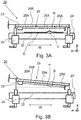
- Fig. 3A shows a cross-section of the sensing 21 unit taken perpendicular to the transport direction D.
- the sheet S is supported on and held against the medium support surface 32 below the support beam 25B.
- the support beam 25B extends from one side of the sheet sensing transport path PP to the opposite side.
- the support beam 25B is at least page-wide compared to the sheets S on the sheet sensing transport path PP.
- the support beam 25B is supported on either lateral side of the medium support surface 32 by actuators 24, 24'.
- the actuators 24, 24' are configured to move in the height direction Y perpendicular to the medium support surface 32 independently of one another.
- the controller 28 preferably determines the individual heights of the respective ends of the support beam 25B and controls the actuators 24, 24' to set their respective height accordingly.
- the emitter 23 is rigidly mounted onto the support beam 25B.
- the angle ⁇ between the beam B of the emitter 23 and the medium support surface 32 can be adjusted by controlling the actuators 24, 24'.
- the emitter 23 is secured to the support beam 25B, so tilting the support beam 25B changes the angle ⁇ of the emitter 23.
- the actuators 24, 24' may be applied for adjusting or setting the height of the emitter 23 with respect to the plane 32 of sheet sensing transport path PP. Both actuators 24, 24' are then driven synchronously to adjust the height of the support beam 25B without changing its angle ⁇ .
- the angle ⁇ may be adjusted by asynchronous movement of one end of the support beam 25B with respect to the other, for example by raising or lowering one actuator 24, 24' as compared to the other actuator 24, 24'.
- a high angular accuracy is achieved by e.g. adjusting the angle ⁇ by controlling the actuator 24' remote from the emitter 23.
- the relatively large lateral distance between the emitter 23 and the actuator 24' allows for precise adjustment of the angle ⁇ . Thereby the distance and angle ⁇ between the medium support surface 32 and the respective emitted optical beam B, B' may be accurately selected and set.
- the sensor assembly 25 generates data or signals which are transmitted to the processor 29.
- the processor 29 compares the received data to a light intensity threshold, which when exceeded prompts the processor 29 to send a sheet unsuitability signal to the controller 28.
- the controller 28 then designates the sensed sheet S as unsuitable for printing.
- the respective sheet S is then preferably removed from the transport path PP by a removal device 26 controlled by the controller 28.
- the support beam 25B further supports the sensor assembly 25, which is formed of a lateral array of sensor devices 25A, such as light sensitive diodes 25A, on the support beam 25B.
- the sensor devices or units 25A form a page-wide sensor array arranged to receive light reflected from deformations D in the sheet S. In Fig.
- the beam B is able to extend freely through the volume between the sheet S and the sensor assembly 25 without a signal light being received by the sensor assembly 25.
- Substantially no light from the emitter 23 is directed onto one or more of the first sensor devices 25A of the sensor assembly 25.
- a signal or intensity below a predefined light intensity threshold then identifies a sheet S as suitable for printing.
- the sensing unit 21 may be optically shielded to prevent ambient light from entering the sensing unit 21.
- the sheet S is deemed suitable for printing and will be passed on to the inkjet marking module 11.
- the height of the beam B over the medium support surface 32 is set to its desired value.
- the height of the emitter 23 and thus of beam B determines the sheet rejection threshold height: sheets S with a maximum sheet height below said height value do not trigger the processor 29 to classify said sheet S as unsuitable for printing and are passed through to the inkjet marking module 11.
- a deformation D passes through the beam B set at its predefined height, light is reflected from the deformation D onto the sensor assembly 25.
- the corresponding data generated by the sensor assembly 25 is transmitted to the processor 29, which, after comparison of the data to a minimum light intensity threshold, classifies the sheet S as unsuited for printing.
- the processor 29 transmits this classification to the controller 28, which then controls the removal device 26 to remove the sheet S from the transport path PP.
- the controller 28 sets the sheet rejection threshold height of the emitter 23, and thus of the optical beam B, at the start of a print job in correspondence to received print job settings. Thereby, the sheet rejection threshold may be adjusted to the specific conditions of the print job, such as the media type used.
- the sensing unit 21 is therefore desirably provided as a separate sentry unit 21 positioned on the transport path PP sufficiently upstream of the inkjet marking module 11.
- the controller 28 and processor 29 may be integrated within the sentry unit 21 or they may be separately or remotely located.
- the apparatus 20 according to the present invention further comprises a removal device 26 or ejector device 26 shown in Fig. 5 for directing a sheet S from the transport path PP to a rejection transport path before said sheet S reaches the inkjet marking module 11.
- the removal device 26 may be a transport switch 26 controlled by the controller 28.
- the controller 28 controls the removal device 26 to direct said sheet S from the transport path PP onto a rejection transport path RP leading to a reject output tray.
- Fig. 3B illustrates the tilting of the support beam 25B.
- the emitter 26 is rigidly fixed to the support beam 25B, such that the optical beam B extends substantially along or parallel to the support beam 25B.
- the actuators 24, 24' tilt the support beam 25B, the angle ⁇ of the beam B with respect to the medium support surface 32 is adjusted.
- the beam B during operation should be parallel to the medium support surface 32.
- the emitter 23 must be tilted with a high degree of precision.
- the actuator 24, 24' each comprise an inherent inaccuracy in positioning their respective side of the support beam 25B, which translates into an inaccuracy of the angle ⁇ .
- Changes to the angle ⁇ are proportional to the ratio between the height changes by an actuator and the length of the support beam 25B in the lateral direction W in between the actuators 24, 24'.
- the influence of the height inaccuracy of the actuators 24, 24' on the angle ⁇ is thereby significantly reduced.
- the present invention thereby allows for finely and accurately tilting the beam B into alignment with the medium support surface 32.
- Fig 4A and 4B of the drawings an embodiment of the alignment method according to the present invention is illustrated.
- a calibration structure 40 is positioned on the lateral right side of the medium support surface 32.
- the calibration structure 40 comprises a body with a well defined lower support surface, such that the calibration structure 40 rests stably on the medium support surface 32 regardless of its exact lateral position.
- the calibration structure 40 has a predefined height, for example by means of a straight top edge, substantially parallel to the medium support surface 32 when resting thereon.
- the emitter 23 is activated and the actuators 24, 24' are driven synchronously to change the height of the support beam 25B and therewith the optical beam B.
- the angle ⁇ of the beam B is not changed.
- the optical beam B is lowered from above the calibration structure 40.
- the calibration structure 40 passes into the beam B and light is reflected onto the sensor assembly 25.
- the controller 28 then stores the height of the actuator 24' on the right side at the moment of detecting the reflected light. This first height value is stored onto the memory of the controller 28.
- the calibration structure 40 is moved to the left side of the medium support surface 32.
- the emitter 23 is activated and the support beam 25B is lowered towards the medium support surface 32.
- the sensor assembly 25 detects when light of the optical beam B reflects of the calibration structure 40 on the left side.
- the controller 28 then stores the height of the right side actuator 24' at the moment of detection as the second height value.
- the first and second height values are then compared to one another to determine an angle parameter for the angle ⁇ of the beam B. This may for example be done by determining a height difference between the first and second height values. This height difference is then divided by the distance between the two positions wherein the calibration structure 40 was positioned. The resulting value is proportional to tan( ⁇ ). From there, a value for the angle ⁇ can be determined.
- the determined angle ⁇ is then compared to a reference to determine whether the angle ⁇ is within predefined tolerances.
- the controller 28 may asynchronously actuate the actuators 24, 24' to adjust the angle ⁇ accordingly such that the beam B is aligned with the medium support surface 32.
- the present invention can be applied to any type of parallel beam emitter based sheet proofing device.
- the detailed embodiments are aimed at a configuration wherein the sensor assembly is positioned to receive light from the sheet only when a deformation comes into contact with the emission beam. For sheets with deformations below a predetermined threshold height no light is reflected from the sheet to the sensor assembly. As explained, this reduces signal noise due to the vibrations in the printing system.
- the beam aligning concept of the present invention can also be applied to a proofing device wherein the sensor assembly is positioned on a laterally opposite side of the transport path with respect to the beam emitter. In case of deformations below the threshold height, the substantially entire emitter beam reaches the sensor assembly.
- Deformations are detected by a drop in intensity as a deformation enters the emission beam and reflects light away from the sensor assembly.
- the reliability of the proofing device is improved by ensuring that the emission beam travels parallel to the plane of the sheet (and/or the transport path), which can be achieved by means the method and apparatus according to the present invention.
- Detailed embodiments of the present invention are disclosed herein; however, it is to be understood that the disclosed embodiments are merely exemplary of the invention, which can be embodied in various forms. Therefore, specific structural and functional details disclosed herein are not to be interpreted as limiting, but merely as a basis for the claims and as a representative basis for teaching one skilled in the art to variously employ the present invention in virtually any appropriately detailed structure.
- any reference to a structural element is intended to encompass any computer executable instructions that instruct a computer to generate such a structural element by three-dimensional printing techniques or similar computer controlled manufacturing techniques.
- such a reference to a structural element encompasses a computer readable medium carrying such computer executable instructions.
Landscapes
- Controlling Sheets Or Webs (AREA)
- Ink Jet (AREA)
Applications Claiming Priority (1)
| Application Number | Priority Date | Filing Date | Title |
|---|---|---|---|
| EP17189004 | 2017-09-01 |
Publications (2)
| Publication Number | Publication Date |
|---|---|
| EP3450184A1 true EP3450184A1 (de) | 2019-03-06 |
| EP3450184B1 EP3450184B1 (de) | 2021-04-21 |
Family
ID=59761833
Family Applications (1)
| Application Number | Title | Priority Date | Filing Date |
|---|---|---|---|
| EP18190060.6A Active EP3450184B1 (de) | 2017-09-01 | 2018-08-21 | Verformungserkennung für druckmedien |
Country Status (1)
| Country | Link |
|---|---|
| EP (1) | EP3450184B1 (de) |
Cited By (1)
| Publication number | Priority date | Publication date | Assignee | Title |
|---|---|---|---|---|
| JP2021017052A (ja) * | 2019-07-18 | 2021-02-15 | 株式会社リコー | 液体吐出装置及び液体吐出方法 |
Citations (4)
| Publication number | Priority date | Publication date | Assignee | Title |
|---|---|---|---|---|
| US20110279507A1 (en) * | 2010-05-11 | 2011-11-17 | Xerox Corporation | Media Handling Device For A Printer |
| JP2012251808A (ja) * | 2011-06-01 | 2012-12-20 | Dainippon Screen Mfg Co Ltd | 検査画像取得装置、パターン検査装置および検査画像取得方法 |
| WO2013098482A1 (en) * | 2011-12-28 | 2013-07-04 | Metso Automation Oy | Measurement of object to be measured |
| EP3017948A1 (de) | 2013-07-02 | 2016-05-11 | FUJIFILM Corporation | Tintenstrahlaufzeichnungsvorrichtung |
-
2018
- 2018-08-21 EP EP18190060.6A patent/EP3450184B1/de active Active
Patent Citations (5)
| Publication number | Priority date | Publication date | Assignee | Title |
|---|---|---|---|---|
| US20110279507A1 (en) * | 2010-05-11 | 2011-11-17 | Xerox Corporation | Media Handling Device For A Printer |
| US8419144B2 (en) | 2010-05-11 | 2013-04-16 | Xerox Corporation | Media handling device for a printer |
| JP2012251808A (ja) * | 2011-06-01 | 2012-12-20 | Dainippon Screen Mfg Co Ltd | 検査画像取得装置、パターン検査装置および検査画像取得方法 |
| WO2013098482A1 (en) * | 2011-12-28 | 2013-07-04 | Metso Automation Oy | Measurement of object to be measured |
| EP3017948A1 (de) | 2013-07-02 | 2016-05-11 | FUJIFILM Corporation | Tintenstrahlaufzeichnungsvorrichtung |
Cited By (1)
| Publication number | Priority date | Publication date | Assignee | Title |
|---|---|---|---|---|
| JP2021017052A (ja) * | 2019-07-18 | 2021-02-15 | 株式会社リコー | 液体吐出装置及び液体吐出方法 |
Also Published As
| Publication number | Publication date |
|---|---|
| EP3450184B1 (de) | 2021-04-21 |
Similar Documents
| Publication | Publication Date | Title |
|---|---|---|
| EP3450185B1 (de) | Fehlererkennung für druckmedien | |
| US10137715B2 (en) | Printing system and method for defect detection in a printing system | |
| US8622495B2 (en) | Paper floating detection apparatus and inkjet recording apparatus | |
| EP3523634B1 (de) | Fehlererkennung für druckmedien | |
| US9465563B2 (en) | Method for defect detection in a printing system and printing system | |
| US8740326B2 (en) | Recording medium lift detection apparatus and inkjet recording apparatus | |
| US9519447B2 (en) | Apparatus and method for determining suitable printing conditions for printing sheets in a printing system | |
| US9850086B2 (en) | Conveyor mechanism and a method for adjusting a conveyor mechanism | |
| JP5608583B2 (ja) | テーブル作成方法及び記録媒体浮き検出装置並びに画像記録装置 | |
| US20090189937A1 (en) | Image forming apparatus | |
| JP5911273B2 (ja) | 読取装置およびプリント装置 | |
| US9738097B2 (en) | Device for redirecting sheets in a printing system | |
| US20160142571A1 (en) | Calibration system for a conveyor mechanism and a method for calibrating a conveyor mechanism | |
| EP3450184B1 (de) | Verformungserkennung für druckmedien | |
| JP6611659B2 (ja) | 媒体の音響検知によるインクジェットプリントヘッド保護 | |
| US10377154B2 (en) | Printing system and method for transporting a print medium in a printing system | |
| US8662623B2 (en) | Printing registered patterns on multiple media sides | |
| US20130163827A1 (en) | Method for detecting artifacts in printed content | |
| US8632153B2 (en) | Printing system having multiple sided pattern registration | |
| US20130162748A1 (en) | Integrated imaging system for printing systems | |
| EP3375618B1 (de) | Detektion von papierkanten während eines unterbrechungsfreien transports | |
| EP3587131A1 (de) | Druckvorrichtung und verfahren zum positionieren einer druckkopfanordnung in einer druckervorrichtung | |
| KR20070052167A (ko) | 잉크젯 프린터 및 이를 이용한 인쇄매체 위치 검출 방법 |
Legal Events
| Date | Code | Title | Description |
|---|---|---|---|
| PUAI | Public reference made under article 153(3) epc to a published international application that has entered the european phase |
Free format text: ORIGINAL CODE: 0009012 |
|
| STAA | Information on the status of an ep patent application or granted ep patent |
Free format text: STATUS: THE APPLICATION HAS BEEN PUBLISHED |
|
| AK | Designated contracting states |
Kind code of ref document: A1 Designated state(s): AL AT BE BG CH CY CZ DE DK EE ES FI FR GB GR HR HU IE IS IT LI LT LU LV MC MK MT NL NO PL PT RO RS SE SI SK SM TR |
|
| AX | Request for extension of the european patent |
Extension state: BA ME |
|
| STAA | Information on the status of an ep patent application or granted ep patent |
Free format text: STATUS: REQUEST FOR EXAMINATION WAS MADE |
|
| 17P | Request for examination filed |
Effective date: 20190906 |
|
| RBV | Designated contracting states (corrected) |
Designated state(s): AL AT BE BG CH CY CZ DE DK EE ES FI FR GB GR HR HU IE IS IT LI LT LU LV MC MK MT NL NO PL PT RO RS SE SI SK SM TR |
|
| RAP1 | Party data changed (applicant data changed or rights of an application transferred) |
Owner name: CANON PRODUCTION PRINTING HOLDING B.V. |
|
| GRAP | Despatch of communication of intention to grant a patent |
Free format text: ORIGINAL CODE: EPIDOSNIGR1 |
|
| STAA | Information on the status of an ep patent application or granted ep patent |
Free format text: STATUS: GRANT OF PATENT IS INTENDED |
|
| RAP1 | Party data changed (applicant data changed or rights of an application transferred) |
Owner name: CANON PRODUCTION PRINTING HOLDING B.V. |
|
| INTG | Intention to grant announced |
Effective date: 20201125 |
|
| GRAS | Grant fee paid |
Free format text: ORIGINAL CODE: EPIDOSNIGR3 |
|
| GRAA | (expected) grant |
Free format text: ORIGINAL CODE: 0009210 |
|
| STAA | Information on the status of an ep patent application or granted ep patent |
Free format text: STATUS: THE PATENT HAS BEEN GRANTED |
|
| AK | Designated contracting states |
Kind code of ref document: B1 Designated state(s): AL AT BE BG CH CY CZ DE DK EE ES FI FR GB GR HR HU IE IS IT LI LT LU LV MC MK MT NL NO PL PT RO RS SE SI SK SM TR |
|
| REG | Reference to a national code |
Ref country code: GB Ref legal event code: FG4D |
|
| REG | Reference to a national code |
Ref country code: CH Ref legal event code: EP |
|
| REG | Reference to a national code |
Ref country code: DE Ref legal event code: R096 Ref document number: 602018015757 Country of ref document: DE Ref country code: IE Ref legal event code: FG4D |
|
| REG | Reference to a national code |
Ref country code: AT Ref legal event code: REF Ref document number: 1384241 Country of ref document: AT Kind code of ref document: T Effective date: 20210515 |
|
| REG | Reference to a national code |
Ref country code: NL Ref legal event code: FP |
|
| REG | Reference to a national code |
Ref country code: LT Ref legal event code: MG9D |
|
| REG | Reference to a national code |
Ref country code: AT Ref legal event code: MK05 Ref document number: 1384241 Country of ref document: AT Kind code of ref document: T Effective date: 20210421 |
|
| PG25 | Lapsed in a contracting state [announced via postgrant information from national office to epo] |
Ref country code: FI Free format text: LAPSE BECAUSE OF FAILURE TO SUBMIT A TRANSLATION OF THE DESCRIPTION OR TO PAY THE FEE WITHIN THE PRESCRIBED TIME-LIMIT Effective date: 20210421 Ref country code: LT Free format text: LAPSE BECAUSE OF FAILURE TO SUBMIT A TRANSLATION OF THE DESCRIPTION OR TO PAY THE FEE WITHIN THE PRESCRIBED TIME-LIMIT Effective date: 20210421 Ref country code: HR Free format text: LAPSE BECAUSE OF FAILURE TO SUBMIT A TRANSLATION OF THE DESCRIPTION OR TO PAY THE FEE WITHIN THE PRESCRIBED TIME-LIMIT Effective date: 20210421 Ref country code: BG Free format text: LAPSE BECAUSE OF FAILURE TO SUBMIT A TRANSLATION OF THE DESCRIPTION OR TO PAY THE FEE WITHIN THE PRESCRIBED TIME-LIMIT Effective date: 20210721 Ref country code: AT Free format text: LAPSE BECAUSE OF FAILURE TO SUBMIT A TRANSLATION OF THE DESCRIPTION OR TO PAY THE FEE WITHIN THE PRESCRIBED TIME-LIMIT Effective date: 20210421 |
|
| PG25 | Lapsed in a contracting state [announced via postgrant information from national office to epo] |
Ref country code: PT Free format text: LAPSE BECAUSE OF FAILURE TO SUBMIT A TRANSLATION OF THE DESCRIPTION OR TO PAY THE FEE WITHIN THE PRESCRIBED TIME-LIMIT Effective date: 20210823 Ref country code: NO Free format text: LAPSE BECAUSE OF FAILURE TO SUBMIT A TRANSLATION OF THE DESCRIPTION OR TO PAY THE FEE WITHIN THE PRESCRIBED TIME-LIMIT Effective date: 20210721 Ref country code: LV Free format text: LAPSE BECAUSE OF FAILURE TO SUBMIT A TRANSLATION OF THE DESCRIPTION OR TO PAY THE FEE WITHIN THE PRESCRIBED TIME-LIMIT Effective date: 20210421 Ref country code: PL Free format text: LAPSE BECAUSE OF FAILURE TO SUBMIT A TRANSLATION OF THE DESCRIPTION OR TO PAY THE FEE WITHIN THE PRESCRIBED TIME-LIMIT Effective date: 20210421 Ref country code: SE Free format text: LAPSE BECAUSE OF FAILURE TO SUBMIT A TRANSLATION OF THE DESCRIPTION OR TO PAY THE FEE WITHIN THE PRESCRIBED TIME-LIMIT Effective date: 20210421 Ref country code: RS Free format text: LAPSE BECAUSE OF FAILURE TO SUBMIT A TRANSLATION OF THE DESCRIPTION OR TO PAY THE FEE WITHIN THE PRESCRIBED TIME-LIMIT Effective date: 20210421 Ref country code: GR Free format text: LAPSE BECAUSE OF FAILURE TO SUBMIT A TRANSLATION OF THE DESCRIPTION OR TO PAY THE FEE WITHIN THE PRESCRIBED TIME-LIMIT Effective date: 20210722 Ref country code: IS Free format text: LAPSE BECAUSE OF FAILURE TO SUBMIT A TRANSLATION OF THE DESCRIPTION OR TO PAY THE FEE WITHIN THE PRESCRIBED TIME-LIMIT Effective date: 20210821 |
|
| REG | Reference to a national code |
Ref country code: DE Ref legal event code: R097 Ref document number: 602018015757 Country of ref document: DE |
|
| PG25 | Lapsed in a contracting state [announced via postgrant information from national office to epo] |
Ref country code: SM Free format text: LAPSE BECAUSE OF FAILURE TO SUBMIT A TRANSLATION OF THE DESCRIPTION OR TO PAY THE FEE WITHIN THE PRESCRIBED TIME-LIMIT Effective date: 20210421 Ref country code: SK Free format text: LAPSE BECAUSE OF FAILURE TO SUBMIT A TRANSLATION OF THE DESCRIPTION OR TO PAY THE FEE WITHIN THE PRESCRIBED TIME-LIMIT Effective date: 20210421 Ref country code: EE Free format text: LAPSE BECAUSE OF FAILURE TO SUBMIT A TRANSLATION OF THE DESCRIPTION OR TO PAY THE FEE WITHIN THE PRESCRIBED TIME-LIMIT Effective date: 20210421 Ref country code: ES Free format text: LAPSE BECAUSE OF FAILURE TO SUBMIT A TRANSLATION OF THE DESCRIPTION OR TO PAY THE FEE WITHIN THE PRESCRIBED TIME-LIMIT Effective date: 20210421 Ref country code: RO Free format text: LAPSE BECAUSE OF FAILURE TO SUBMIT A TRANSLATION OF THE DESCRIPTION OR TO PAY THE FEE WITHIN THE PRESCRIBED TIME-LIMIT Effective date: 20210421 Ref country code: CZ Free format text: LAPSE BECAUSE OF FAILURE TO SUBMIT A TRANSLATION OF THE DESCRIPTION OR TO PAY THE FEE WITHIN THE PRESCRIBED TIME-LIMIT Effective date: 20210421 Ref country code: DK Free format text: LAPSE BECAUSE OF FAILURE TO SUBMIT A TRANSLATION OF THE DESCRIPTION OR TO PAY THE FEE WITHIN THE PRESCRIBED TIME-LIMIT Effective date: 20210421 |
|
| PLBE | No opposition filed within time limit |
Free format text: ORIGINAL CODE: 0009261 |
|
| STAA | Information on the status of an ep patent application or granted ep patent |
Free format text: STATUS: NO OPPOSITION FILED WITHIN TIME LIMIT |
|
| 26N | No opposition filed |
Effective date: 20220124 |
|
| REG | Reference to a national code |
Ref country code: CH Ref legal event code: PL |
|
| PG25 | Lapsed in a contracting state [announced via postgrant information from national office to epo] |
Ref country code: MC Free format text: LAPSE BECAUSE OF FAILURE TO SUBMIT A TRANSLATION OF THE DESCRIPTION OR TO PAY THE FEE WITHIN THE PRESCRIBED TIME-LIMIT Effective date: 20210421 |
|
| REG | Reference to a national code |
Ref country code: BE Ref legal event code: MM Effective date: 20210831 |
|
| PG25 | Lapsed in a contracting state [announced via postgrant information from national office to epo] |
Ref country code: LI Free format text: LAPSE BECAUSE OF NON-PAYMENT OF DUE FEES Effective date: 20210831 Ref country code: CH Free format text: LAPSE BECAUSE OF NON-PAYMENT OF DUE FEES Effective date: 20210831 |
|
| PG25 | Lapsed in a contracting state [announced via postgrant information from national office to epo] |
Ref country code: IS Free format text: LAPSE BECAUSE OF FAILURE TO SUBMIT A TRANSLATION OF THE DESCRIPTION OR TO PAY THE FEE WITHIN THE PRESCRIBED TIME-LIMIT Effective date: 20210821 Ref country code: LU Free format text: LAPSE BECAUSE OF NON-PAYMENT OF DUE FEES Effective date: 20210821 Ref country code: AL Free format text: LAPSE BECAUSE OF FAILURE TO SUBMIT A TRANSLATION OF THE DESCRIPTION OR TO PAY THE FEE WITHIN THE PRESCRIBED TIME-LIMIT Effective date: 20210421 |
|
| PG25 | Lapsed in a contracting state [announced via postgrant information from national office to epo] |
Ref country code: IT Free format text: LAPSE BECAUSE OF FAILURE TO SUBMIT A TRANSLATION OF THE DESCRIPTION OR TO PAY THE FEE WITHIN THE PRESCRIBED TIME-LIMIT Effective date: 20210421 Ref country code: IE Free format text: LAPSE BECAUSE OF NON-PAYMENT OF DUE FEES Effective date: 20210821 Ref country code: FR Free format text: LAPSE BECAUSE OF NON-PAYMENT OF DUE FEES Effective date: 20210831 Ref country code: BE Free format text: LAPSE BECAUSE OF NON-PAYMENT OF DUE FEES Effective date: 20210831 |
|
| GBPC | Gb: european patent ceased through non-payment of renewal fee |
Effective date: 20220821 |
|
| PG25 | Lapsed in a contracting state [announced via postgrant information from national office to epo] |
Ref country code: CY Free format text: LAPSE BECAUSE OF FAILURE TO SUBMIT A TRANSLATION OF THE DESCRIPTION OR TO PAY THE FEE WITHIN THE PRESCRIBED TIME-LIMIT Effective date: 20210421 |
|
| PG25 | Lapsed in a contracting state [announced via postgrant information from national office to epo] |
Ref country code: HU Free format text: LAPSE BECAUSE OF FAILURE TO SUBMIT A TRANSLATION OF THE DESCRIPTION OR TO PAY THE FEE WITHIN THE PRESCRIBED TIME-LIMIT; INVALID AB INITIO Effective date: 20180821 |
|
| PG25 | Lapsed in a contracting state [announced via postgrant information from national office to epo] |
Ref country code: GB Free format text: LAPSE BECAUSE OF NON-PAYMENT OF DUE FEES Effective date: 20220821 |
|
| PG25 | Lapsed in a contracting state [announced via postgrant information from national office to epo] |
Ref country code: MK Free format text: LAPSE BECAUSE OF FAILURE TO SUBMIT A TRANSLATION OF THE DESCRIPTION OR TO PAY THE FEE WITHIN THE PRESCRIBED TIME-LIMIT Effective date: 20210421 |
|
| PGFP | Annual fee paid to national office [announced via postgrant information from national office to epo] |
Ref country code: NL Payment date: 20240722 Year of fee payment: 7 |
|
| PG25 | Lapsed in a contracting state [announced via postgrant information from national office to epo] |
Ref country code: MT Free format text: LAPSE BECAUSE OF FAILURE TO SUBMIT A TRANSLATION OF THE DESCRIPTION OR TO PAY THE FEE WITHIN THE PRESCRIBED TIME-LIMIT Effective date: 20210421 |
|
| PGFP | Annual fee paid to national office [announced via postgrant information from national office to epo] |
Ref country code: DE Payment date: 20240821 Year of fee payment: 7 |
|
| PG25 | Lapsed in a contracting state [announced via postgrant information from national office to epo] |
Ref country code: TR Free format text: LAPSE BECAUSE OF FAILURE TO SUBMIT A TRANSLATION OF THE DESCRIPTION OR TO PAY THE FEE WITHIN THE PRESCRIBED TIME-LIMIT Effective date: 20210421 |
|
| REG | Reference to a national code |
Ref country code: DE Ref legal event code: R119 Ref document number: 602018015757 Country of ref document: DE |
|
| REG | Reference to a national code |
Ref country code: NL Ref legal event code: MM Effective date: 20250901 |