EP3450095A1 - Automated interchangeable coolant distributor - Google Patents
Automated interchangeable coolant distributor Download PDFInfo
- Publication number
- EP3450095A1 EP3450095A1 EP18191323.7A EP18191323A EP3450095A1 EP 3450095 A1 EP3450095 A1 EP 3450095A1 EP 18191323 A EP18191323 A EP 18191323A EP 3450095 A1 EP3450095 A1 EP 3450095A1
- Authority
- EP
- European Patent Office
- Prior art keywords
- cooling fluid
- fixed nozzle
- cutting region
- control valve
- machine tool
- Prior art date
- Legal status (The legal status is an assumption and is not a legal conclusion. Google has not performed a legal analysis and makes no representation as to the accuracy of the status listed.)
- Withdrawn
Links
Images

Classifications
-
- B—PERFORMING OPERATIONS; TRANSPORTING
- B23—MACHINE TOOLS; METAL-WORKING NOT OTHERWISE PROVIDED FOR
- B23Q—DETAILS, COMPONENTS, OR ACCESSORIES FOR MACHINE TOOLS, e.g. ARRANGEMENTS FOR COPYING OR CONTROLLING; MACHINE TOOLS IN GENERAL CHARACTERISED BY THE CONSTRUCTION OF PARTICULAR DETAILS OR COMPONENTS; COMBINATIONS OR ASSOCIATIONS OF METAL-WORKING MACHINES, NOT DIRECTED TO A PARTICULAR RESULT
- B23Q11/00—Accessories fitted to machine tools for keeping tools or parts of the machine in good working condition or for cooling work; Safety devices specially combined with or arranged in, or specially adapted for use in connection with, machine tools
- B23Q11/10—Arrangements for cooling or lubricating tools or work
- B23Q11/1076—Arrangements for cooling or lubricating tools or work with a cutting liquid nozzle specially adaptable to different kinds of machining operations
-
- B—PERFORMING OPERATIONS; TRANSPORTING
- B23—MACHINE TOOLS; METAL-WORKING NOT OTHERWISE PROVIDED FOR
- B23Q—DETAILS, COMPONENTS, OR ACCESSORIES FOR MACHINE TOOLS, e.g. ARRANGEMENTS FOR COPYING OR CONTROLLING; MACHINE TOOLS IN GENERAL CHARACTERISED BY THE CONSTRUCTION OF PARTICULAR DETAILS OR COMPONENTS; COMBINATIONS OR ASSOCIATIONS OF METAL-WORKING MACHINES, NOT DIRECTED TO A PARTICULAR RESULT
- B23Q11/00—Accessories fitted to machine tools for keeping tools or parts of the machine in good working condition or for cooling work; Safety devices specially combined with or arranged in, or specially adapted for use in connection with, machine tools
- B23Q11/14—Methods or arrangements for maintaining a constant temperature in parts of machine tools
- B23Q11/141—Methods or arrangements for maintaining a constant temperature in parts of machine tools using a closed fluid circuit for cooling or heating
-
- B—PERFORMING OPERATIONS; TRANSPORTING
- B23—MACHINE TOOLS; METAL-WORKING NOT OTHERWISE PROVIDED FOR
- B23Q—DETAILS, COMPONENTS, OR ACCESSORIES FOR MACHINE TOOLS, e.g. ARRANGEMENTS FOR COPYING OR CONTROLLING; MACHINE TOOLS IN GENERAL CHARACTERISED BY THE CONSTRUCTION OF PARTICULAR DETAILS OR COMPONENTS; COMBINATIONS OR ASSOCIATIONS OF METAL-WORKING MACHINES, NOT DIRECTED TO A PARTICULAR RESULT
- B23Q11/00—Accessories fitted to machine tools for keeping tools or parts of the machine in good working condition or for cooling work; Safety devices specially combined with or arranged in, or specially adapted for use in connection with, machine tools
- B23Q11/14—Methods or arrangements for maintaining a constant temperature in parts of machine tools
- B23Q11/146—Methods or arrangements for maintaining a constant temperature in parts of machine tools by controlling the temperature of a cutting liquid
-
- B—PERFORMING OPERATIONS; TRANSPORTING
- B23—MACHINE TOOLS; METAL-WORKING NOT OTHERWISE PROVIDED FOR
- B23Q—DETAILS, COMPONENTS, OR ACCESSORIES FOR MACHINE TOOLS, e.g. ARRANGEMENTS FOR COPYING OR CONTROLLING; MACHINE TOOLS IN GENERAL CHARACTERISED BY THE CONSTRUCTION OF PARTICULAR DETAILS OR COMPONENTS; COMBINATIONS OR ASSOCIATIONS OF METAL-WORKING MACHINES, NOT DIRECTED TO A PARTICULAR RESULT
- B23Q11/00—Accessories fitted to machine tools for keeping tools or parts of the machine in good working condition or for cooling work; Safety devices specially combined with or arranged in, or specially adapted for use in connection with, machine tools
- B23Q11/10—Arrangements for cooling or lubricating tools or work
- B23Q11/1084—Arrangements for cooling or lubricating tools or work specially adapted for being fitted to different kinds of machines
-
- Y—GENERAL TAGGING OF NEW TECHNOLOGICAL DEVELOPMENTS; GENERAL TAGGING OF CROSS-SECTIONAL TECHNOLOGIES SPANNING OVER SEVERAL SECTIONS OF THE IPC; TECHNICAL SUBJECTS COVERED BY FORMER USPC CROSS-REFERENCE ART COLLECTIONS [XRACs] AND DIGESTS
- Y10—TECHNICAL SUBJECTS COVERED BY FORMER USPC
- Y10T—TECHNICAL SUBJECTS COVERED BY FORMER US CLASSIFICATION
- Y10T408/00—Cutting by use of rotating axially moving tool
- Y10T408/44—Cutting by use of rotating axially moving tool with means to apply transient, fluent medium to work or product
- Y10T408/45—Cutting by use of rotating axially moving tool with means to apply transient, fluent medium to work or product including Tool with duct
- Y10T408/458—Cutting by use of rotating axially moving tool with means to apply transient, fluent medium to work or product including Tool with duct including nozzle
-
- Y—GENERAL TAGGING OF NEW TECHNOLOGICAL DEVELOPMENTS; GENERAL TAGGING OF CROSS-SECTIONAL TECHNOLOGIES SPANNING OVER SEVERAL SECTIONS OF THE IPC; TECHNICAL SUBJECTS COVERED BY FORMER USPC CROSS-REFERENCE ART COLLECTIONS [XRACs] AND DIGESTS
- Y10—TECHNICAL SUBJECTS COVERED BY FORMER USPC
- Y10T—TECHNICAL SUBJECTS COVERED BY FORMER US CLASSIFICATION
- Y10T408/00—Cutting by use of rotating axially moving tool
- Y10T408/44—Cutting by use of rotating axially moving tool with means to apply transient, fluent medium to work or product
- Y10T408/46—Cutting by use of rotating axially moving tool with means to apply transient, fluent medium to work or product including nozzle
-
- Y—GENERAL TAGGING OF NEW TECHNOLOGICAL DEVELOPMENTS; GENERAL TAGGING OF CROSS-SECTIONAL TECHNOLOGIES SPANNING OVER SEVERAL SECTIONS OF THE IPC; TECHNICAL SUBJECTS COVERED BY FORMER USPC CROSS-REFERENCE ART COLLECTIONS [XRACs] AND DIGESTS
- Y10—TECHNICAL SUBJECTS COVERED BY FORMER USPC
- Y10T—TECHNICAL SUBJECTS COVERED BY FORMER US CLASSIFICATION
- Y10T409/00—Gear cutting, milling, or planing
- Y10T409/30—Milling
- Y10T409/303976—Milling with means to control temperature or lubricate
Definitions
- the present disclosure is related to machine cutting fluid or coolant systems. More specifically, the disclosure relates to an interchangeable nozzle assembly with a variety of fixed spray nozzles for a cutting machine coolant distributor.
- Cutting fluid or coolant
- Metal cutting operations generate heat due to friction between a tool and a workpiece.
- the heat generated is from energy lost deforming the material and needs to be carried away.
- Water is a conductor of heat but is not stable at high temperatures, so stability is often achieved by making an emulsion of water with oil. The goal is to keep the workpiece at a stable temperature and maximize the life of the cutting tool by lubricating its working edge to reduce tip welding.
- the coolant stream must be aimed at the point where the cutting tool is removing metal.
- Manual systems require machine operators to constantly adjust the coolant systems to make sure coolant is aimed in the right position to flood the work zone. While coolant lines and nozzles are easy to adjust, having to make adjustments every time a tool change takes place is inefficient. It is also dangerous if an operator reaches into a machine with its spindle turning.
- What is desired is an apparatus that can be applied to an existing milling or grinding machine that targets coolant to a best location on a cutting tool in response to a machine program and allows machine operators to leave a machine untended for extended periods.
- a coolant distributor comprising a head having a plurality of ports, each of the ports being fluidly coupled to a flow control valve; a cap demountably coupled to the head, the cap comprising at least one fixed nozzle fluidly coupled to at least one port; a controller coupled to the flow control valve, wherein the controller is configured to actuate the flow control valve to pass a cooling fluid through the at least one fixed nozzle to direct the cooling fluid to at least one predetermined cutting region of a machine tool and work piece proximate the coolant distributor.
- each of the at least one fixed nozzle is configured to direct the cooling fluid to a particular one of the at least one predetermined cutting region.
- the at least one predetermined cutting region corresponds to a location for the application of the cooling fluid to control a temperature and a lubrication level of the machine tool and the work piece for removal of material.
- the at least one predetermined cutting region varies responsive to the type of machine tool and work piece and responsive to changes in a shape of the machine tool and a shape of the work piece.
- the head is configured to receive a variety of caps, each the cap being configured for at least one predetermined machine tool and work piece.
- the controller includes data comprising coordinates of the at least one predetermined cutting region corresponding to the machine tool and the work piece.
- the flow control valve is fluidly coupled to more than one fixed nozzle.
- a coolant distributor for a machine tool comprising a head having ports fluidly coupled to a cooling fluid reservoir; a flow control valve fluidly coupled to the ports and the cooling fluid reservoir; a controller coupled to the flow control valve; a cap attached to the head, the cap comprising at least one fixed nozzle, the at least one fixed nozzle fluidly coupled to at least one of the ports, the fixed nozzle configured to direct the cooling fluid to a predetermined cutting region of the machine tool and a work piece.
- the cap is interchangeable with additional caps having different fixed nozzle configurations corresponding to a predetermined cutting region.
- the fixed nozzles direct the cooling fluid to the predetermined cutting region in the absence of adjustment.
- the controller is coupled to a computer numerical control apparatus.
- the cutting region is a location requiring application of the cooling fluid for control of a temperature and a lubrication of the machine tool and the work piece.
- the controller is configured to selectively actuate the flow control valve to flow the cooling fluid through a particular nozzle configured to direct the cooling fluid to the predetermined cutting region responsive to the machine tool and the work piece.
- a process for lubricating and cooling a machine tool and a work piece during a variety of machining operations comprising selectively flowing a cooling fluid through a first fixed nozzle to a first predetermined cutting region responsive to a controller; and selectively flowing a cooling fluid through a second fixed nozzle to a second predetermined cutting region responsive to the controller.
- the process further comprises fluidly coupling a cooling fluid reservoir to the first fixed nozzle through a first flow control valve; and fluidly coupling the cooling fluid reservoir to the second fixed nozzle through a second flow control valve.
- the first flow control valve is fluidly coupled to a first port formed in a head; the second flow control valve is fluidly coupled to a second port formed in the head; the first fixed nozzle and the second fixed nozzle being coupled to a first cap attached to the head.
- the process further comprises changing the first cap for second cap having a third fixed nozzle configured to direct the cooling fluid to a third predetermined cutting region.
- the process further comprises matching the first predetermined cutting region and the second predetermined cutting region to the machine tool and the work piece responsive to the changes in shape and size of the machine tool and the work piece.
- first fixed nozzle and the second fixed nozzle are preset with the absence of adjustment during operation.
- the coolant distributor 10 comprises a head 12 and a cap 14.
- the cap 14 is demountably attached to the head 12.
- the head 12 includes a plurality of ports 16 formed in the head 12.
- the ports 16 are configured to selectively couple a cooling fluid 18 to the cap 14.
- the cooling fluid 18 is designed to both cool and lubricate.
- a cooling fluid reservoir 20 is fluidly coupled to the head 12 through cooling fluid tube 22.
- a pressure relief valve 24 is coupled to the cooling fluid tube 22 and configured to release the cooling fluid 18 at a predetermined pressure to protect the cooling fluid tube 22, and other fluid components in the coolant distributor 10.
- a flow control valve 26 is fluidly coupled to each port 16 in the head 12. In an exemplary embodiment, there is a flow control valve 26 for each port 16. In another exemplary embodiment, there can be a flow control valve 26 for a predetermined number of ports 16.
- the flow control valve 26 is coupled to and selectively actuated by a controller 28.
- the controller 28 can be part of the computer numerical control (CNC) apparatus that enables the machining process.
- the flow control valve 26 can be a solenoid valve, pneumatic valve and the like.
- the cap 14 includes a plurality of nozzles 30.
- the nozzles 30 are fixed nozzles and configured to direct the cooling fluid 18 at a cutting region 32.
- the fixed nozzles 30 are not adjusted by a machine operator.
- the fixed nozzles 30 are preset and configured to direct the cooling fluid 18 to the proper cutting region 32 without the need for a machine operator's manipulation.
- the cutting region 32 is the location where a machine tool 34 contacts a work piece 36 on a table 38 during the machining process.
- the cutting region 32 is the location that requires the application of the cooling fluid 18 to control the temperature and lubrication of the machine tool 34 and work piece 36 for material removal.
- the cap 14 has multiple fixed nozzles 30 configured to direct the cooling fluid 18 to a specific predetermined cutting region 32 depending on the type of machine tool 34 and work piece 36 selected. As the machine tool 34 changes shape and size dimensions as well as the work piece changes shape and size dimensions the location of the cutting region 32 changes. Thus, each of the fixed nozzles 30 are configured to direct the cooling fluid 18 to a particular predetermined cutting region 32.
- the controller 28 opens the particular flow control valve 26 to flow cooling fluid 18 through a particular port 16 to a particular nozzle 30 for directing the cooling fluid 18 for a particular cutting region 32 responsive to the anticipated location of the predetermined cutting region 32.
- caps 14 there can be multiple caps 14 that are interchangeable for attaching to the head 12.
- the head 12 can be configured as a universal head that accepts a variety of caps 14.
- the caps 14 can be configured with nozzles specific to the machining process and work piece 36 being machined.
- the caps 14 can be interchanged as needed depending upon the work piece 36 and machining process.
- a cap 14 can be configured to function with one or more predetermined machining process and/or work piece. Each cap 14 can accommodate many machine tools 34.
- the control valves 26 in the ports 16 in the head 12 are each controlled to flow cooling fluid 18 to a particular nozzle 30 in the cap 14.
- the controller 28 has databases that include the predetermined coordinates of each cutting region 32.
- the machine tool 34 can include a grinding wheel, a drill, a cutting edge, a turning insert, a milling tool, and the like.
- an exemplary coolant distributor 10 is illustrated with a lathe 40.
- the lathe 40 with chuck 42 holding the work piece 36 turns the work piece 36 as the machine tool 34 mounted in the tool post 44 cuts the work piece 36.
- the coolant distributor 10 can be mounted to the tool post 44.
- Multiple machine tool 34 configurations can be assembled in a tool magazine 46.
- the cap 14 can include a nozzle 30 configuration that enables multiple machine tools 34 resulting in multiple cutting regions 32 without the need to adjust the fixed nozzles 30 of the coolant distributor 10.
- the coolant distributor 10 has a flexible configuration that allows for placement of the coolant distributor 10 in multiple locations for optimal coolant fluid 18 application.
- FIG. 3 illustrates another exemplary embodiment with the coolant distributor 10 coupled with a milling machine 48.
- the coolant distributor 10 is attached to the machine table 38 inside the milling machine cabinet 50.
- the coolant distributor 10 can be located for optimal delivery of the cooling fluid 18 to the cutting region 32.
- the disclosed coolant distributor allows for coolant delivery into the cutting zone without manual adjustment of the fixed nozzles of the coolant distributor.
- the disclosed coolant distributor eliminates the cycle time required for changing coolant nozzles for different parts and/or machining tools.
- the disclosed coolant distributor can be mounted in a variety of locations near the machining operation enabling coolant delivery to the cutting region consistently.
- the disclosed coolant distributor can be integrated into both a turret head a machine table or a fixed point within the machine.
- the disclosed coolant distributor includes a cap that houses all of the nozzles required for a particular machine and part as well as a selection of a variety of caps each with varying fixed nozzle geometries configured for predetermined cooling fluid distribution.
- the disclosed coolant distributor allows for the flow of cooling fluid to a variety of cutting regions for a variety of machine tools and work pieces before a cooling fluid nozzle adjustment is needed.
Landscapes
- Engineering & Computer Science (AREA)
- Mechanical Engineering (AREA)
- Auxiliary Devices For Machine Tools (AREA)
Abstract
Description
- The present disclosure is related to machine cutting fluid or coolant systems. More specifically, the disclosure relates to an interchangeable nozzle assembly with a variety of fixed spray nozzles for a cutting machine coolant distributor.
- Milling and grinding machines need to have coolant directed to specific areas during cutting. Cutting fluid, or coolant, is liquid used to cool and lubricate the cutting edges of machine tools and the pieces they are shaping. It is pumped over the cutting site of machines such as lathes, milling machines, shapers, grinders and saws.
- Metal cutting operations generate heat due to friction between a tool and a workpiece. The heat generated is from energy lost deforming the material and needs to be carried away. Water is a conductor of heat but is not stable at high temperatures, so stability is often achieved by making an emulsion of water with oil. The goal is to keep the workpiece at a stable temperature and maximize the life of the cutting tool by lubricating its working edge to reduce tip welding.
- To ensure cutting edge cooling, the coolant stream must be aimed at the point where the cutting tool is removing metal. Manual systems require machine operators to constantly adjust the coolant systems to make sure coolant is aimed in the right position to flood the work zone. While coolant lines and nozzles are easy to adjust, having to make adjustments every time a tool change takes place is inefficient. It is also dangerous if an operator reaches into a machine with its spindle turning.
- The benefits of keeping coolant on target make substantial contributions to productivity. It minimizes the risk of damaging heat build-up in the workpiece or cutting tool thereby preserving tool life. It allows optimal feed rates and speeds to be applied more safely and flushes away swarfs and chips.
- What is desired is an apparatus that can be applied to an existing milling or grinding machine that targets coolant to a best location on a cutting tool in response to a machine program and allows machine operators to leave a machine untended for extended periods.
- In accordance with the present disclosure, there is provided a coolant distributor comprising a head having a plurality of ports, each of the ports being fluidly coupled to a flow control valve; a cap demountably coupled to the head, the cap comprising at least one fixed nozzle fluidly coupled to at least one port; a controller coupled to the flow control valve, wherein the controller is configured to actuate the flow control valve to pass a cooling fluid through the at least one fixed nozzle to direct the cooling fluid to at least one predetermined cutting region of a machine tool and work piece proximate the coolant distributor.
- In another and alternative embodiment, each of the at least one fixed nozzle is configured to direct the cooling fluid to a particular one of the at least one predetermined cutting region.
- In another and alternative embodiment, the at least one predetermined cutting region corresponds to a location for the application of the cooling fluid to control a temperature and a lubrication level of the machine tool and the work piece for removal of material.
- In another and alternative embodiment, the at least one predetermined cutting region varies responsive to the type of machine tool and work piece and responsive to changes in a shape of the machine tool and a shape of the work piece.
- In another and alternative embodiment, the head is configured to receive a variety of caps, each the cap being configured for at least one predetermined machine tool and work piece.
- In another and alternative embodiment, the controller includes data comprising coordinates of the at least one predetermined cutting region corresponding to the machine tool and the work piece.
- In another and alternative embodiment, the flow control valve is fluidly coupled to more than one fixed nozzle.
- In accordance with the present disclosure, there is provided a coolant distributor for a machine tool comprising a head having ports fluidly coupled to a cooling fluid reservoir; a flow control valve fluidly coupled to the ports and the cooling fluid reservoir; a controller coupled to the flow control valve; a cap attached to the head, the cap comprising at least one fixed nozzle, the at least one fixed nozzle fluidly coupled to at least one of the ports, the fixed nozzle configured to direct the cooling fluid to a predetermined cutting region of the machine tool and a work piece.
- In another and alternative embodiment, the cap is interchangeable with additional caps having different fixed nozzle configurations corresponding to a predetermined cutting region.
- In another and alternative embodiment, the fixed nozzles direct the cooling fluid to the predetermined cutting region in the absence of adjustment.
- In another and alternative embodiment, the controller is coupled to a computer numerical control apparatus.
- In another and alternative embodiment, the cutting region is a location requiring application of the cooling fluid for control of a temperature and a lubrication of the machine tool and the work piece.
- In another and alternative embodiment, the controller is configured to selectively actuate the flow control valve to flow the cooling fluid through a particular nozzle configured to direct the cooling fluid to the predetermined cutting region responsive to the machine tool and the work piece.
- In accordance with the present disclosure, there is provided a process for lubricating and cooling a machine tool and a work piece during a variety of machining operations comprising selectively flowing a cooling fluid through a first fixed nozzle to a first predetermined cutting region responsive to a controller; and selectively flowing a cooling fluid through a second fixed nozzle to a second predetermined cutting region responsive to the controller.
- In another and alternative embodiment, the process further comprises fluidly coupling a cooling fluid reservoir to the first fixed nozzle through a first flow control valve; and fluidly coupling the cooling fluid reservoir to the second fixed nozzle through a second flow control valve.
- In another and alternative embodiment, the first flow control valve is fluidly coupled to a first port formed in a head; the second flow control valve is fluidly coupled to a second port formed in the head; the first fixed nozzle and the second fixed nozzle being coupled to a first cap attached to the head.
- In another and alternative embodiment, the process further comprises changing the first cap for second cap having a third fixed nozzle configured to direct the cooling fluid to a third predetermined cutting region.
- In another and alternative embodiment, the process further comprises matching the first predetermined cutting region and the second predetermined cutting region to the machine tool and the work piece responsive to the changes in shape and size of the machine tool and the work piece.
- In another and alternative embodiment, the first fixed nozzle and the second fixed nozzle are preset with the absence of adjustment during operation.
- Other details of the coolant distributor are set forth in the following detailed description and the accompanying drawings wherein like reference numerals depict like elements.
-
-
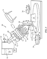
FIG. 1 is a schematic representation of an exemplary coolant distributor with a machining tool. -
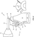
FIG. 2 is a schematic representation of an exemplary coolant distributor with a lathe. -
FIG. 3 is a schematic representation of an exemplary coolant distributor with a milling machine. - Referring now to
FIG. 1 , there is illustrated anexemplary coolant distributor 10. Thecoolant distributor 10 comprises ahead 12 and acap 14. Thecap 14 is demountably attached to thehead 12. Thehead 12 includes a plurality ofports 16 formed in thehead 12. Theports 16 are configured to selectively couple acooling fluid 18 to thecap 14. Thecooling fluid 18 is designed to both cool and lubricate. Acooling fluid reservoir 20 is fluidly coupled to thehead 12 throughcooling fluid tube 22. Apressure relief valve 24 is coupled to thecooling fluid tube 22 and configured to release thecooling fluid 18 at a predetermined pressure to protect thecooling fluid tube 22, and other fluid components in thecoolant distributor 10. - A
flow control valve 26 is fluidly coupled to eachport 16 in thehead 12. In an exemplary embodiment, there is aflow control valve 26 for eachport 16. In another exemplary embodiment, there can be aflow control valve 26 for a predetermined number ofports 16. Theflow control valve 26 is coupled to and selectively actuated by acontroller 28. In an exemplary embodiment, thecontroller 28 can be part of the computer numerical control (CNC) apparatus that enables the machining process. In an exemplary embodiment, theflow control valve 26 can be a solenoid valve, pneumatic valve and the like. - The
cap 14 includes a plurality ofnozzles 30. Thenozzles 30 are fixed nozzles and configured to direct thecooling fluid 18 at acutting region 32. Thefixed nozzles 30 are not adjusted by a machine operator. Thefixed nozzles 30 are preset and configured to direct thecooling fluid 18 to theproper cutting region 32 without the need for a machine operator's manipulation. Thecutting region 32 is the location where amachine tool 34 contacts awork piece 36 on a table 38 during the machining process. Thecutting region 32 is the location that requires the application of thecooling fluid 18 to control the temperature and lubrication of themachine tool 34 andwork piece 36 for material removal. - The
cap 14 has multiplefixed nozzles 30 configured to direct thecooling fluid 18 to a specific predeterminedcutting region 32 depending on the type ofmachine tool 34 andwork piece 36 selected. As themachine tool 34 changes shape and size dimensions as well as the work piece changes shape and size dimensions the location of the cuttingregion 32 changes. Thus, each of the fixednozzles 30 are configured to direct the coolingfluid 18 to a particularpredetermined cutting region 32. Thecontroller 28 opens the particularflow control valve 26 to flow coolingfluid 18 through aparticular port 16 to aparticular nozzle 30 for directing the coolingfluid 18 for aparticular cutting region 32 responsive to the anticipated location of thepredetermined cutting region 32. - In an exemplary embodiment, there can be
multiple caps 14 that are interchangeable for attaching to thehead 12. Thehead 12 can be configured as a universal head that accepts a variety ofcaps 14. Thecaps 14 can be configured with nozzles specific to the machining process and workpiece 36 being machined. Thecaps 14 can be interchanged as needed depending upon thework piece 36 and machining process. Acap 14 can be configured to function with one or more predetermined machining process and/or work piece. Eachcap 14 can accommodatemany machine tools 34. - The
control valves 26 in theports 16 in thehead 12 are each controlled to flow coolingfluid 18 to aparticular nozzle 30 in thecap 14. Thecontroller 28 has databases that include the predetermined coordinates of each cuttingregion 32. - The
machine tool 34 can include a grinding wheel, a drill, a cutting edge, a turning insert, a milling tool, and the like. - Referring to
FIG. 2 anexemplary coolant distributor 10 is illustrated with alathe 40. Thelathe 40 withchuck 42 holding thework piece 36 turns thework piece 36 as themachine tool 34 mounted in thetool post 44 cuts thework piece 36. In an exemplary embodiment, thecoolant distributor 10 can be mounted to thetool post 44.Multiple machine tool 34 configurations can be assembled in a tool magazine 46. Thecap 14 can include anozzle 30 configuration that enablesmultiple machine tools 34 resulting inmultiple cutting regions 32 without the need to adjust the fixednozzles 30 of thecoolant distributor 10. Thecoolant distributor 10 has a flexible configuration that allows for placement of thecoolant distributor 10 in multiple locations foroptimal coolant fluid 18 application. -
FIG. 3 illustrates another exemplary embodiment with thecoolant distributor 10 coupled with amilling machine 48. Thecoolant distributor 10 is attached to the machine table 38 inside themilling machine cabinet 50.
Thecoolant distributor 10 can be located for optimal delivery of the coolingfluid 18 to the cuttingregion 32. - The disclosed coolant distributor allows for coolant delivery into the cutting zone without manual adjustment of the fixed nozzles of the coolant distributor.
- The disclosed coolant distributor eliminates the cycle time required for changing coolant nozzles for different parts and/or machining tools.
- The disclosed coolant distributor can be mounted in a variety of locations near the machining operation enabling coolant delivery to the cutting region consistently.
- The disclosed coolant distributor can be integrated into both a turret head a machine table or a fixed point within the machine.
- The disclosed coolant distributor includes a cap that houses all of the nozzles required for a particular machine and part as well as a selection of a variety of caps each with varying fixed nozzle geometries configured for predetermined cooling fluid distribution.
- The disclosed coolant distributor allows for the flow of cooling fluid to a variety of cutting regions for a variety of machine tools and work pieces before a cooling fluid nozzle adjustment is needed.
- There has been provided a coolant distributor. While the coolant distributor has been described in the context of specific embodiments thereof, other unforeseen alternatives, modifications, and variations may become apparent to those skilled in the art having read the foregoing description. Accordingly, it is intended to embrace those alternatives, modifications, and variations which fall within the broad scope of the appended claims.
Claims (15)
- A coolant distributor comprising:a head having a plurality of ports, each of said ports being fluidly coupled to a flow control valve;a cap demountably coupled to said head, said cap comprising at least one fixed nozzle fluidly coupled to at least one port;a controller coupled to said flow control valve, wherein said controller is configured to actuate said flow control valve to pass a cooling fluid through said at least one fixed nozzle to direct said cooling fluid to at least one predetermined cutting region of a machine tool and work piece proximate the coolant distributor.
- The coolant distributor according to claim 1, wherein said at least one predetermined cutting region varies responsive to the type of machine tool and work piece and responsive to changes in a shape of said machine tool and a shape of said work piece.
- The coolant distributor according to claim 1 or 2, wherein said head is configured to receive a variety of caps, each said cap being configured for at least one predetermined machine tool and work piece.
- The coolant distributor according to claim 1, 2 or 3, wherein said controller includes data comprising coordinates of said at least one predetermined cutting region corresponding to said machine tool and said work piece, wherein, optionally, said flow control valve is fluidly coupled to more than one fixed nozzle.
- A coolant distributor for a machine tool comprising:a head having ports fluidly coupled to a cooling fluid reservoir;a flow control valve fluidly coupled to said ports and said cooling fluid reservoir;a controller coupled to said flow control valve;a cap attached to said head, said cap comprising at least one fixed nozzle, said at least one fixed nozzle fluidly coupled to at least one of said ports, said fixed nozzle configured to direct said cooling fluid to a predetermined cutting region of said machine tool and a work piece.
- The coolant distributor according to claim 5, wherein said cap is interchangeable with additional caps having different fixed nozzle configurations corresponding to a predetermined cutting region.
- The coolant distributor according to any one of claims 1-6, wherein each of said at least one fixed nozzles is configured to direct said cooling fluid to a particular one of said predetermined cutting region in the absence of adjustment.
- The coolant distributor according to any one of claims 5-7, wherein said controller is coupled to a computer numerical control apparatus.
- The coolant distributor according to any one of claims 1-8, wherein said predetermined cutting region corresponds to a location requiring application of said cooling fluid for control of a temperature and a lubrication of said machine tool and said work piece.
- The coolant distributor according to any one of claims 5-9, wherein said controller is configured to selectively actuate said flow control valve to flow said cooling fluid through a particular nozzle configured to direct said cooling fluid to said predetermined cutting region responsive to said machine tool and said work piece.
- A process for lubricating and cooling a machine tool and a work piece during a variety of machining operations comprising:selectively flowing a cooling fluid through a first fixed nozzle to a first predetermined cutting region responsive to a controller; andselectively flowing a cooling fluid through a second fixed nozzle to a second predetermined cutting region responsive to said controller.
- The process of claim 11, further comprising:fluidly coupling a cooling fluid reservoir to said first fixed nozzle through a first flow control valve; andfluidly coupling said cooling fluid reservoir to said second fixed nozzle through a second flow control valve.
- The process of claim 12, wherein said first flow control valve is fluidly coupled to a first port formed in a head; said second flow control valve is fluidly coupled to a second port formed in said head; said first fixed nozzle and said second fixed nozzle being coupled to a first cap attached to said head, wherein, optionally, said first fixed nozzle and said second fixed nozzle are preset with the absence of adjustment during operation.
- The process of claim 12 or 13, further comprising:changing said first cap for second cap having a third fixed nozzle configured to direct said cooling fluid to a third predetermined cutting region.
- The process of any one of claims 11-14, further comprising;
matching said first predetermined cutting region and said second predetermined cutting region to the machine tool and the work piece responsive to the changes in shape and size of the machine tool and the work piece.
Applications Claiming Priority (1)
| Application Number | Priority Date | Filing Date | Title |
|---|---|---|---|
| US15/688,321 US10610992B2 (en) | 2017-08-28 | 2017-08-28 | Automated interchangeable coolant distributor |
Publications (1)
| Publication Number | Publication Date |
|---|---|
| EP3450095A1 true EP3450095A1 (en) | 2019-03-06 |
Family
ID=63442546
Family Applications (1)
| Application Number | Title | Priority Date | Filing Date |
|---|---|---|---|
| EP18191323.7A Withdrawn EP3450095A1 (en) | 2017-08-28 | 2018-08-28 | Automated interchangeable coolant distributor |
Country Status (2)
| Country | Link |
|---|---|
| US (1) | US10610992B2 (en) |
| EP (1) | EP3450095A1 (en) |
Families Citing this family (3)
| Publication number | Priority date | Publication date | Assignee | Title |
|---|---|---|---|---|
| JP6603288B2 (en) * | 2017-10-25 | 2019-11-06 | ファナック株式会社 | Cutting fluid supply device for machine tools |
| WO2023276120A1 (en) * | 2021-07-01 | 2023-01-05 | Dmg森精機株式会社 | Machine tool, control method, and control program |
| CN117359385B (en) * | 2023-12-08 | 2024-03-08 | 烟台隆辉金属制品有限公司 | Machine tool cutter temperature control device |
Citations (3)
| Publication number | Priority date | Publication date | Assignee | Title |
|---|---|---|---|---|
| DE29900753U1 (en) * | 1999-01-18 | 1999-04-22 | Hawema Werkzeugschleifmaschinen GmbH, 78647 Trossingen | Coolant supply system for cutting machine tools |
| US6241432B1 (en) * | 1998-10-23 | 2001-06-05 | Brookdale Associates | Machine tool accessory high pressure fluid distribution system |
| US20110318123A1 (en) * | 2010-06-23 | 2011-12-29 | Leishman James | Multiple zone cooling apparatus |
Family Cites Families (21)
| Publication number | Priority date | Publication date | Assignee | Title |
|---|---|---|---|---|
| BE509890A (en) * | 1951-05-29 | 1900-01-01 | ||
| US2929566A (en) * | 1955-03-03 | 1960-03-22 | Paasche Company | Cooling method and apparatus for metal working |
| US3726363A (en) * | 1971-06-08 | 1973-04-10 | Twining E | Coolant spider assembly |
| US3868195A (en) * | 1973-09-14 | 1975-02-25 | Cincinnati Milacron Heald | Coolant system for machine tool |
| US3893355A (en) | 1973-12-21 | 1975-07-08 | Giddings & Lewis | Coolant supply system for cutting tools in a machine tool |
| US4778315A (en) * | 1986-09-26 | 1988-10-18 | The Boeing Company | Chip removal and tool lubricating device and method |
| US5349731A (en) * | 1991-05-07 | 1994-09-27 | Hardinge Brothers, Inc. | Temperature compensated and shock resistant machine tool |
| US5297657A (en) * | 1991-07-25 | 1994-03-29 | Brittani-7, Inc. | High pressure coolant system for machine tools |
| DE4129402A1 (en) | 1991-09-04 | 1993-03-11 | Blohm Maschinenbau Gmbh | COOLING DEVICE FOR A GRINDING MACHINE |
| US5190421A (en) * | 1991-11-20 | 1993-03-02 | Hardinge Brothers, Inc. | Coolant supply system for a machine tool |
| US5245152A (en) * | 1992-06-09 | 1993-09-14 | Klein Tools, Inc. | Dielectric fluid dust extraction system for electric discharge machine |
| US5265505A (en) * | 1992-10-29 | 1993-11-30 | Frechette Eugene L | Turret-lathe coolant system |
| US5993121A (en) * | 1997-05-20 | 1999-11-30 | The Boeing Company | Cooling device for multi-axis rotary machining tool |
| US7727054B2 (en) | 2002-07-26 | 2010-06-01 | Saint-Gobain Abrasives, Inc. | Coherent jet nozzles for grinding applications |
| AU2004230856B2 (en) | 2003-03-31 | 2008-07-24 | The Gleason Works | Coolant delivery apparatus for machine tool |
| IL181834A (en) | 2006-04-02 | 2011-04-28 | Iscar Ltd | Cutting head and adaptor |
| US7878096B2 (en) | 2006-10-11 | 2011-02-01 | United Technologies Corporation | CNC coolant nozzle |
| DE102010036316B4 (en) | 2010-07-09 | 2015-06-11 | Saint-Gobain Diamantwerkzeuge Gmbh | Nozzle for cooling lubricant |
| US9238287B2 (en) | 2011-05-23 | 2016-01-19 | Dimensional Control, Inc. | Multi-nozzle machine tool cooling system |
| DE102012104263A1 (en) * | 2012-05-16 | 2013-11-21 | Walter Maschinenbau Gmbh | Coolant distributor for a machine tool |
| DE102012018389A1 (en) * | 2012-09-18 | 2014-03-20 | Maximilian Bähr | Device for spraying medium on processing location of e.g. drill used for processing workpieces made of metal, has pivoting device engaging at nozzle bodies, and causing simultaneous pivoting of nozzle bodies |
-
2017
- 2017-08-28 US US15/688,321 patent/US10610992B2/en active Active
-
2018
- 2018-08-28 EP EP18191323.7A patent/EP3450095A1/en not_active Withdrawn
Patent Citations (3)
| Publication number | Priority date | Publication date | Assignee | Title |
|---|---|---|---|---|
| US6241432B1 (en) * | 1998-10-23 | 2001-06-05 | Brookdale Associates | Machine tool accessory high pressure fluid distribution system |
| DE29900753U1 (en) * | 1999-01-18 | 1999-04-22 | Hawema Werkzeugschleifmaschinen GmbH, 78647 Trossingen | Coolant supply system for cutting machine tools |
| US20110318123A1 (en) * | 2010-06-23 | 2011-12-29 | Leishman James | Multiple zone cooling apparatus |
Also Published As
| Publication number | Publication date |
|---|---|
| US10610992B2 (en) | 2020-04-07 |
| US20190061082A1 (en) | 2019-02-28 |
Similar Documents
| Publication | Publication Date | Title |
|---|---|---|
| EP1911548A1 (en) | CNC coolant nozzle | |
| EP0579371B1 (en) | A method and an apparatus for machining a workpiece | |
| KR101291210B1 (en) | Cnc deep hole drilling center with automatic tool and bush change | |
| US7441484B1 (en) | CNC prescribe method to encourage chip breaking | |
| US20180056465A1 (en) | Fluid ejection device | |
| US5272945A (en) | Toolholder assembly and method | |
| EP3450095A1 (en) | Automated interchangeable coolant distributor | |
| US10814447B2 (en) | Cooling system and method for machine tools | |
| US4375708A (en) | Non-indexing machining method and apparatus | |
| KR20110006582U (en) | Machines and methods for processing cast or forged outer ring | |
| JP2012115971A (en) | Machine tool, and tool holder thereof | |
| JPH06134648A (en) | Cutting method and device | |
| JP6314636B2 (en) | Cutting device | |
| KR20160097627A (en) | Cutting oil automatic feeding equipment of cnc machine tool with the remote control function | |
| JP6555145B2 (en) | Cutting tool, processing device having cutting tool, and processing method using cutting tool | |
| US8413680B2 (en) | Fluid distribution apparatus | |
| CN210307014U (en) | Inflating valve processing lathe | |
| KR101672543B1 (en) | Method for controlling injection pressure | |
| JP2016064462A (en) | Machine tool and workpiece machining method | |
| CN215845730U (en) | Numerical control machining chip removing equipment for coil shell | |
| KR102582433B1 (en) | Cutting tool having a cooling path inside the tool | |
| RU2162399C1 (en) | Metal-cutting machine tool | |
| KR20200048577A (en) | Coolant supply apparatus for machine tool | |
| JP2002346809A (en) | Cutting tool for drilling and drilling method using the tool | |
| CN114055334A (en) | Flexible honing and reaming device suitable for precision machining of valve core hole of hydraulic multi-way valve |
Legal Events
| Date | Code | Title | Description |
|---|---|---|---|
| PUAI | Public reference made under article 153(3) epc to a published international application that has entered the european phase |
Free format text: ORIGINAL CODE: 0009012 |
|
| STAA | Information on the status of an ep patent application or granted ep patent |
Free format text: STATUS: THE APPLICATION HAS BEEN PUBLISHED |
|
| AK | Designated contracting states |
Kind code of ref document: A1 Designated state(s): AL AT BE BG CH CY CZ DE DK EE ES FI FR GB GR HR HU IE IS IT LI LT LU LV MC MK MT NL NO PL PT RO RS SE SI SK SM TR |
|
| AX | Request for extension of the european patent |
Extension state: BA ME |
|
| STAA | Information on the status of an ep patent application or granted ep patent |
Free format text: STATUS: REQUEST FOR EXAMINATION WAS MADE |
|
| 17P | Request for examination filed |
Effective date: 20190904 |
|
| RBV | Designated contracting states (corrected) |
Designated state(s): AL AT BE BG CH CY CZ DE DK EE ES FI FR GB GR HR HU IE IS IT LI LT LU LV MC MK MT NL NO PL PT RO RS SE SI SK SM TR |
|
| RAP1 | Party data changed (applicant data changed or rights of an application transferred) |
Owner name: RAYTHEON TECHNOLOGIES CORPORATION |
|
| STAA | Information on the status of an ep patent application or granted ep patent |
Free format text: STATUS: EXAMINATION IS IN PROGRESS |
|
| 17Q | First examination report despatched |
Effective date: 20211020 |
|
| STAA | Information on the status of an ep patent application or granted ep patent |
Free format text: STATUS: THE APPLICATION IS DEEMED TO BE WITHDRAWN |
|
| 18D | Application deemed to be withdrawn |
Effective date: 20230310 |