EP3449891B1 - Kolbenbasierte brustkompressionsvorrichtung mit riemenantrieb - Google Patents
Kolbenbasierte brustkompressionsvorrichtung mit riemenantrieb Download PDFInfo
- Publication number
- EP3449891B1 EP3449891B1 EP18198976.5A EP18198976A EP3449891B1 EP 3449891 B1 EP3449891 B1 EP 3449891B1 EP 18198976 A EP18198976 A EP 18198976A EP 3449891 B1 EP3449891 B1 EP 3449891B1
- Authority
- EP
- European Patent Office
- Prior art keywords
- piston
- belt
- backboard
- drive spool
- patient
- Prior art date
- Legal status (The legal status is an assumption and is not a legal conclusion. Google has not performed a legal analysis and makes no representation as to the accuracy of the status listed.)
- Active
Links
Images




Classifications
-
- A—HUMAN NECESSITIES
- A61—MEDICAL OR VETERINARY SCIENCE; HYGIENE
- A61H—PHYSICAL THERAPY APPARATUS, e.g. DEVICES FOR LOCATING OR STIMULATING REFLEX POINTS IN THE BODY; ARTIFICIAL RESPIRATION; MASSAGE; BATHING DEVICES FOR SPECIAL THERAPEUTIC OR HYGIENIC PURPOSES OR SPECIFIC PARTS OF THE BODY
- A61H31/00—Artificial respiration by a force applied to the chest; Heart stimulation, e.g. heart massage
- A61H31/004—Heart stimulation
- A61H31/006—Power driven
-
- A—HUMAN NECESSITIES
- A61—MEDICAL OR VETERINARY SCIENCE; HYGIENE
- A61H—PHYSICAL THERAPY APPARATUS, e.g. DEVICES FOR LOCATING OR STIMULATING REFLEX POINTS IN THE BODY; ARTIFICIAL RESPIRATION; MASSAGE; BATHING DEVICES FOR SPECIAL THERAPEUTIC OR HYGIENIC PURPOSES OR SPECIFIC PARTS OF THE BODY
- A61H11/00—Belts, strips or combs for massage purposes
- A61H2011/005—Belts, strips or combs for massage purposes with belt or strap expanding and contracting around an encircled body part
-
- A—HUMAN NECESSITIES
- A61—MEDICAL OR VETERINARY SCIENCE; HYGIENE
- A61H—PHYSICAL THERAPY APPARATUS, e.g. DEVICES FOR LOCATING OR STIMULATING REFLEX POINTS IN THE BODY; ARTIFICIAL RESPIRATION; MASSAGE; BATHING DEVICES FOR SPECIAL THERAPEUTIC OR HYGIENIC PURPOSES OR SPECIFIC PARTS OF THE BODY
- A61H2201/00—Characteristics of apparatus not provided for in the preceding codes
- A61H2201/12—Driving means
- A61H2201/1207—Driving means with electric or magnetic drive
- A61H2201/1215—Rotary drive
-
- A—HUMAN NECESSITIES
- A61—MEDICAL OR VETERINARY SCIENCE; HYGIENE
- A61H—PHYSICAL THERAPY APPARATUS, e.g. DEVICES FOR LOCATING OR STIMULATING REFLEX POINTS IN THE BODY; ARTIFICIAL RESPIRATION; MASSAGE; BATHING DEVICES FOR SPECIAL THERAPEUTIC OR HYGIENIC PURPOSES OR SPECIFIC PARTS OF THE BODY
- A61H2201/00—Characteristics of apparatus not provided for in the preceding codes
- A61H2201/12—Driving means
- A61H2201/1238—Driving means with hydraulic or pneumatic drive
- A61H2201/1246—Driving means with hydraulic or pneumatic drive by piston-cylinder systems
-
- A—HUMAN NECESSITIES
- A61—MEDICAL OR VETERINARY SCIENCE; HYGIENE
- A61H—PHYSICAL THERAPY APPARATUS, e.g. DEVICES FOR LOCATING OR STIMULATING REFLEX POINTS IN THE BODY; ARTIFICIAL RESPIRATION; MASSAGE; BATHING DEVICES FOR SPECIAL THERAPEUTIC OR HYGIENIC PURPOSES OR SPECIFIC PARTS OF THE BODY
- A61H2201/00—Characteristics of apparatus not provided for in the preceding codes
- A61H2201/16—Physical interface with patient
- A61H2201/1657—Movement of interface, i.e. force application means
- A61H2201/1664—Movement of interface, i.e. force application means linear
-
- A—HUMAN NECESSITIES
- A61—MEDICAL OR VETERINARY SCIENCE; HYGIENE
- A61H—PHYSICAL THERAPY APPARATUS, e.g. DEVICES FOR LOCATING OR STIMULATING REFLEX POINTS IN THE BODY; ARTIFICIAL RESPIRATION; MASSAGE; BATHING DEVICES FOR SPECIAL THERAPEUTIC OR HYGIENIC PURPOSES OR SPECIFIC PARTS OF THE BODY
- A61H2201/00—Characteristics of apparatus not provided for in the preceding codes
- A61H2201/50—Control means thereof
-
- A—HUMAN NECESSITIES
- A61—MEDICAL OR VETERINARY SCIENCE; HYGIENE
- A61H—PHYSICAL THERAPY APPARATUS, e.g. DEVICES FOR LOCATING OR STIMULATING REFLEX POINTS IN THE BODY; ARTIFICIAL RESPIRATION; MASSAGE; BATHING DEVICES FOR SPECIAL THERAPEUTIC OR HYGIENIC PURPOSES OR SPECIFIC PARTS OF THE BODY
- A61H2201/00—Characteristics of apparatus not provided for in the preceding codes
- A61H2201/50—Control means thereof
- A61H2201/5058—Sensors or detectors
- A61H2201/5064—Position sensors
-
- A—HUMAN NECESSITIES
- A61—MEDICAL OR VETERINARY SCIENCE; HYGIENE
- A61H—PHYSICAL THERAPY APPARATUS, e.g. DEVICES FOR LOCATING OR STIMULATING REFLEX POINTS IN THE BODY; ARTIFICIAL RESPIRATION; MASSAGE; BATHING DEVICES FOR SPECIAL THERAPEUTIC OR HYGIENIC PURPOSES OR SPECIFIC PARTS OF THE BODY
- A61H2201/00—Characteristics of apparatus not provided for in the preceding codes
- A61H2201/50—Control means thereof
- A61H2201/5058—Sensors or detectors
- A61H2201/5071—Pressure sensors
-
- A—HUMAN NECESSITIES
- A61—MEDICAL OR VETERINARY SCIENCE; HYGIENE
- A61H—PHYSICAL THERAPY APPARATUS, e.g. DEVICES FOR LOCATING OR STIMULATING REFLEX POINTS IN THE BODY; ARTIFICIAL RESPIRATION; MASSAGE; BATHING DEVICES FOR SPECIAL THERAPEUTIC OR HYGIENIC PURPOSES OR SPECIFIC PARTS OF THE BODY
- A61H2201/00—Characteristics of apparatus not provided for in the preceding codes
- A61H2201/50—Control means thereof
- A61H2201/5058—Sensors or detectors
- A61H2201/5079—Velocity sensors
-
- A—HUMAN NECESSITIES
- A61—MEDICAL OR VETERINARY SCIENCE; HYGIENE
- A61H—PHYSICAL THERAPY APPARATUS, e.g. DEVICES FOR LOCATING OR STIMULATING REFLEX POINTS IN THE BODY; ARTIFICIAL RESPIRATION; MASSAGE; BATHING DEVICES FOR SPECIAL THERAPEUTIC OR HYGIENIC PURPOSES OR SPECIFIC PARTS OF THE BODY
- A61H2201/00—Characteristics of apparatus not provided for in the preceding codes
- A61H2201/50—Control means thereof
- A61H2201/5058—Sensors or detectors
- A61H2201/5092—Optical sensor
-
- A—HUMAN NECESSITIES
- A61—MEDICAL OR VETERINARY SCIENCE; HYGIENE
- A61H—PHYSICAL THERAPY APPARATUS, e.g. DEVICES FOR LOCATING OR STIMULATING REFLEX POINTS IN THE BODY; ARTIFICIAL RESPIRATION; MASSAGE; BATHING DEVICES FOR SPECIAL THERAPEUTIC OR HYGIENIC PURPOSES OR SPECIFIC PARTS OF THE BODY
- A61H31/00—Artificial respiration by a force applied to the chest; Heart stimulation, e.g. heart massage
- A61H31/008—Supine patient supports or bases, e.g. improving air-way access to the lungs
Definitions
- CPR cardiopulmonary resuscitation
- Cardiopulmonary resuscitation is a well-known and valuable method of first aid used to resuscitate people who have suffered from cardiac arrest.
- CPR requires repetitive chest compressions to squeeze the heart and the thoracic cavity to pump blood through the body.
- Artificial respiration such as mouth-to-mouth breathing or bag mask respiration, is used to supply air to the lungs.
- blood flow in the body is about 25% to 30% of normal blood flow.
- Patent 7,410,470 show chest compression devices that compress a patient's chest with a belt.
- Our commercial device, sold under the trademark AUTOPULSE ® is described in some detail in our prior patents, including Jensen, Lightweight Electro-Mechanical Chest Compression Device, U.S. Patent 7,347,832 (March 25, 2008 ) and Quintana, et al., Methods and Devices for Attaching a Belt Cartridge to a Chest Compression Device, U.S. Patent 7,354,407 (April 8, 2008 ).
- US 2010/0198118 describes a cardiac massage device (CMD) having a foldable and rigid support structure, an electric motor incorporated into the support structure and a plate plunger connected to the motor by a driving mechanism.
- the support structure comprises a length-adjustable base element, a height-adjustable element and a length-adjustable plunger-carrying element.
- the connection angles between the elements of the support structure can be varied by hinge units.
- WO 03/024336 describes a cardiopulmonary resuscitation apparatus comprising sternal compression means having a piston for compressing the sternum and thoracic constriction means having a chest band for fastening and constricting the chest when the compression means compresses a patient's chest.
- the apparatus further comprises length adjusting means for adjusting the length of the chest band according to the size of the patient's chest.
- US 2004/0230140 relates to systems and procedures for treating cardiac arrest. In the resuscitation the victim chest is mechanically compressed and decompressed to stimulate the heart. The victim is induced to inspire and expire against insufflating breathing gas during the chest compression/decompressions.
- the hybrid chest compression device includes a backboard with a motor and a drive spool housed within the backboard.
- the motor is operably secured to the drive spool to cyclically wind and unwind the belt which is enclosed within the backboard and the piston support frame and is secured to the drive spool.
- the piston support frame has two legs and a piston actuator housing and the frame is secured to the backboard forming a channel between the two legs, the backboard and the piston actuator housing to accommodate the patient.
- the piston is operably housed within the piston actuator housing and the piston is driven by movement of the belt.
- Two or more sets of guide spindles are located in the backboard and the piston support frame for guiding the belt and forming a belt path through the backboard and the piston support frame.
- FIG 1 illustrates the chest compression device fitted on a patient 1.
- the chest compression device 4 applies compressions with the piston 5.
- the piston is disposed within a housing 6 which is supported over the patient with a frame or gantry 7 with two legs 7L and 7R fixed to a backboard 8.
- the frame When disposed about the patient, the frame extends over thorax 2 of the patient so that the piston is disposed apposing sternum 2A of the patient as shown in Figure 2 .
- Piston 5 may include a compression pad 9 adapted to contact the patient's chest, directly over the sternum, to impart compressive force on the patient's chest.
- the chest compression device is controlled using a control system which is operated by a rescuer through interface 10, which may include a display to provide instructions and prompts to a rescuer and includes an input device to accept operating instructions from the rescuer.
- piston 5 is driven by a belt 14 which is tightened and loosened when spooled upon a drive spool 15.
- the drive spool is mounted in the housing used as the backboard 8.
- Motor 16 within backboard 8 is operably connected to drive spool 15.
- the belt is connected to drive spool 15 such that cyclic rotation of motor 16 cyclically rotates drive spool 15 which spools and unspools belt 14 onto and off of drive spool 15.
- This spooling and unspooling may also be described as winding and unwinding or wrapping and unwrapping.
- the cyclic spooling and unspooling of belt 14 onto and off of drive spool 15 cyclically shortens and lengthens the span of belt 14 surrounding patient 1.
- the path or course of belt 14, such as path 17, through backboard 8, frame 7 and piston housing 6 has a fixed length such that shortening the span of belt 14 from span 17A to span 17B (shown in Figure 5 ) causes belt 14 to exert compressive force 18 on piston 5.
- Cyclic spooling and unspooling of belt 14 onto and off of drive spool 15 causes cyclic exertion of compressive force 18 to piston 5, and from piston 5 to patient's sternum 2A.
- Belt path 17 may optionally include guide spindles to control belt 14 and belt path 17 and minimize friction on the belt when belt 14 moves through the frame, backboard and piston housing.
- upper guide spindles 20 and lower guide spindles 22 minimize friction and constrain belt path 17.
- Any suitable number of guide spindles may be provided throughout backboard 8, support frame 7 and piston housing 6 such as intermediate guide spindles 23 which may also be provided within piston housing 6.
- chest compression device 4 may be slid over patient 1 until the patient is oriented with piston 5 apposing sternum 2A.
- chest compression device 24 shown in Figures 2 and 2A may include access opening 25 in at least one support leg such as support leg 7L.
- Belt 14 has first and second ends 14A and 14B respectively which overlap and are accessible through access opening 25.
- First and second belt ends 14A and 14B each include cooperating attachment elements such as hook and loop fasteners or other suitable fasteners. Separation of first belt end 14A from second belt end 14B permits support leg 7L to be lifted free of backboard 8.
- Patient 1 is then oriented on backboard 8, support leg 7L is reengaged to backboard 8 with patient 1 extending through access opening or channel 26, first and second belt ends 14A and 14B are reconnected to each other and chest compression device 24 is ready to provide chest compressions to patient 1.
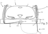
- Chest compression device 30 of Figure 3 illustrates another configuration for opening the chest compression device to engage a patient such as patient 1.
- First support leg 31 A is attached to backboard 32 using any suitable attachment mechanism and first end 33 A of belt 33 is attached to drive spool 34 while belt second end 33B is removably attached to the drive spool to enable insertion of a patient into patient channel 35.
- Second support leg 31B frictionally engages leg socket 36 of backboard 32.
- Belt second end 33B passes through socket 36, around one or more guide spindles such as guide spindle 37, and is removably attached to drive spool 34 using a clip, spline or other suitable attachment means such as clip 38.
- second support leg 31B With belt second end 33B disengaged from drive spool 34, second support leg 31B is disengaged from socket 36. Second support leg 31B with belt second end 33B extending from the leg is moved to enable insertion of patient 1 into patient channel 35. When patient 1 is properly oriented on backboard 32, belt second end 33B is passed through socket 36 and second support leg 31B is inserted into socket 36. Belt second end 33B passes around guide spindle 37 and clip 38 is then secured to drive spool 34 and chest compression device 30 is ready to perform mechanical CPR.
- any of chest compression devices 4, 24 or 30, results in a controller such as controller 42 controlling operation of motor 16.
- Motor 16 which is operably connected to drive spool 15 rotates first clockwise, and then counter-clockwise. Alternatively, counter rotation of the drive spool may be accomplished with a releasing clutch and a spring return, a motor driven return or other suitable mechanism.
- the drive belt such as drive belt 14 is operably connected to drive spool 15 such that the alternating rotation and counter-rotation first spools or winds the belt onto the drive spool and then unspools or unwinds the belt from the drive spool.
- the cyclic spooling and unspooling of the belt cyclically shortens and lengthens the span of the belt as discussed above.
- belt 14 and piston 5 are in position 43A as illustrated Figure 2 .
- Rotation of the motor and drive spool which spools or winds belt 14 onto the drive spool shortens the span of the belt to span 17B and urges piston 5 into fully extended position 43B of Figure 5 .
- piston 5 compresses patient's thorax 2 with compressive force 18 applied to sternum 2A.
- Counter-rotation of drive spool 15 releases tension on belt 14 and the resilience of the patient's thorax will cause decompression of the thorax which will urge piston 5 back into position 43A.
- any suitable spring such as spring 44 may be compressed by the extension of piston 5 into position 43B. The force of compressed spring 44 and release of tension on belt 14 will urge piston 5 back into retracted position 43A and may assist in chest decompression.
- FIG. 1 defines a device for performing mechanical cardiopulmonary resuscitation comprising, inter alia, a motor
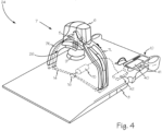
- Figure 6 shows an automatic chest compression device 50 with a pneumatic drive system as illustrated in our copending U.S. Patent Application 13/234,980 filed September 16, 2011 which is incorporated herein by reference in its entirety.
- Chest compression device 50 includes a backboard 51, with the belt 52, which has a right belt portion 52R and a left belt portion 52L.
- Right and left belt portions 52L and 52R extend around vertically oriented spindles 54L and 54R and then extend along the superior/inferior (head-to-toe vis-a-vis the patient) axis the of the device to joint 55 which secures the belt to actuator rod 56 which also extends along the superior/inferior axis of the device to a pneumatic piston 57.
- the pneumatic piston is operable to pull the rod superiorly (upward relative to the patient) and thereby tighten the band which extends piston 5 to compress the patient's chest, and push the rod inferiorly (downward relative to the patient).
- the pneumatic piston is supplied with fluid through hoses 58 and 59, communicating with a pressurized fluid source 60 through input hose 61 and valve 62.
- the valve may be controlled through control system 63 and interface 10.
- control system 63 and interface 10 Using commonly available 150 psi (10.2 atmospheres) air supply, and an actuator with a volume of approximately 10 cubic inches (about 164 milliliters) or larger, and a stroke of about 6 inches (about 15.24 cm), the piston can pull and push the rod and thus pull and release the straps, such that the compression belt is tightened about the patient at a rate sufficient for CPR and a depth sufficient for CPR (i.e., at resuscitative rate and depth).
- the control system may be a computer control system, programmed to control the valve to alternately supply high pressure air to one side of the piston to pull the straps and then supply air to the other side of the piston to release tension on the straps (while in each case venting the other side of the piston), or an electromechanical control system.
- the control system may be a microprocessor or separate computer system, integrated into the backboard or a separate computer control system located remotely.
- the load plate and load cells shown in our U.S. Patent 7,347,832 may be placed on the upper surface of the platform, such that it is disposed under the patient's thorax when the system is installed on a patient.
- a compression depth monitor may be used to provide feedback regarding the effect of compressions, as disclosed in out U.S. Patent 7,122,014 .
- the position of the actuator rod 56 can be detected with a linear encoder system, with an index on the actuator rod and a nearby encoder reader mounted within the platform, with an linear variable differential transformer (LVDT), string potentiometer, or other means for detecting the linear position of the actuator rod, or with the load cells.
- LVDT linear variable differential transformer
- the point at which the belt has been tightened and there is no slack in the belt around the patient, and the belt is merely snug about the patient but has not exerted significant compressive force on the patient's chest may be detected by sensing a rapid increase in the actuator pressure, a slow-down in the movement of the actuator rod (as determined by the encoder, LVDT or other means for detecting the linear position of the actuator rod, or a sharp initial increase in load on the load plate and load sensor.
- the control system may be programmed to detect such signals indicative of the point at which slack has been taken up, and establish the corresponding position of the actuator rod as a starting point for compressions.
Landscapes
- Health & Medical Sciences (AREA)
- Cardiology (AREA)
- Heart & Thoracic Surgery (AREA)
- Emergency Medicine (AREA)
- Pulmonology (AREA)
- Epidemiology (AREA)
- Pain & Pain Management (AREA)
- Physical Education & Sports Medicine (AREA)
- Rehabilitation Therapy (AREA)
- Life Sciences & Earth Sciences (AREA)
- Animal Behavior & Ethology (AREA)
- General Health & Medical Sciences (AREA)
- Public Health (AREA)
- Veterinary Medicine (AREA)
- Percussion Or Vibration Massage (AREA)
Claims (11)
- Vorrichtung (4, 24, 50) zum Durchführen einer mechanischen kardiopulmonalen Wiederbelebung an einem Patienten, umfassend:ein Rückbrett (8, 32, 51);einen Motor (16);einen Kolbenunterstützungsrahmen (7) mit zwei Beinen (7L, 7R, 31A, 31B) und einem Aktuatorgehäuse (6), wobei der Kolbenunterstützungsrahmen an dem Rückbrett befestigt ist und einen Kanal (26) zwischen den beiden Beinen, dem Rückbrett und dem Aktuatorgehäuse bildet, wobei eines der beiden Beine von einer Buchse (36) in dem Rückbrett entkoppelt werden kann;einen Kolben (5), der im Kolbenaktuatorgehäuse funktionsfähig untergebracht ist;eine Schnittstelle (10); undeine Steuerung (42), die so konfiguriert ist, dass sie die Betätigung und den Betrieb des Motors (16) steuert, um ein zyklisches Aus- und Einfahren des Kolbens gegen den Brustkorb des Patienten zu bewirken, um eine Kompression des Brustkorbs und eine unterstützte Dekompression während der mechanischen kardiopulmonalen Wiederbelebung durchzuführen, wobei die Steuerung (42) und die Schnittstelle (10) in das Rückbrett (8, 32, 51) integriert sind.
- Vorrichtung nach Anspruch 1, ferner umfassend eine Feder (44), die funktionsfähig mit dem Kolben in Eingriff steht und den Kolben in eine zurückgezogene Position drückt, um die unterstützte Dekompression während der mechanischen kardiopulmonalen Wiederbelebung zu bewirken.
- Vorrichtung nach Anspruch 1, ferner umfassend:eine Antriebsspule (15, 34), die in dem Rückbrett untergebracht ist, wobei der Motor funktionsfähig an der Antriebsspule befestigt ist;einen Riemen (14, 52), der innerhalb des Rückbretts und des Unterstützungsrahmens des Kolbens eingeschlossen ist, wobei der Riemen funktionsfähig an der Antriebsspule befestigt ist;wobei die Betätigung des Motors zu einer zyklischen Drehung und Gegendrehung des Motors und einem entsprechenden Auf- und Abwickeln des Riemens auf der Antriebsspule führt, um das zyklische Aus- und Einfahren des Kolbens gegen den Brustkorb des Patienten zu bewirken, um die Kompression des Brustkorbs und die unterstützte Dekompression während der mechanischen kardiopulmonalen Wiederbelebung durchzuführen.
- Vorrichtung nach Anspruch 3, ferner umfassend:
eine Vielzahl von Führungsspindeln (20, 22, 23, 37) in dem Rückbrett und dem Unterstützungsrahmen für den Kolben zur Führung des Riemens und zur Bildung eines Riemenpfades durch das Rückbrett und den Kolbenunterstützungsrahmen. - Vorrichtung nach Anspruch 3, wobei der Riemen ein erstes (14A, 33A) und ein zweites (14B, 33B) Ende aufweist, die sich überlappen und durch eine Zugangsöffnung (25) in einem der Stützbeine (7L, 7R, 31A, 31B) zugänglich sind.
- Vorrichtung nach Anspruch 5, wobei das erste und das zweite Riemenende jeweils zusammenwirkende Befestigungselemente wie Haken- und Ösenverschlüsse oder andere geeignete Befestigungen einschließen.
- Vorrichtung nach Anspruch 5, wobei das erste Ende an der Antriebsspule befestigt ist und das zweite Ende entfernbar an der Antriebsspule befestigt ist.
- Vorrichtung nach Anspruch 5, wobei das zweite Ende mit einem Clip (38) entfernbar an der Antriebsspule befestigt ist.
- Vorrichtung nach Anspruch 6, wobei das zweite Ende unter Verwendung eines Keils entfernbar an der Antriebsspule befestigt ist.
- Vorrichtung nach Anspruch 3, ferner umfassend:
einer Auslösekupplung und einem Federrückzug, um die Antriebsspule gegenläufig zu drehen und den Riemen abzuwickeln. - Vorrichtung nach Anspruch 1, die so konfiguriert ist, dass die eingefahrene Position des Kolbens einer unterstützten Dekompressionsposition entspricht.
Applications Claiming Priority (3)
| Application Number | Priority Date | Filing Date | Title |
|---|---|---|---|
| US13/971,727 US9211229B2 (en) | 2013-08-20 | 2013-08-20 | Piston-based chest compression device with belt drive |
| PCT/US2014/047172 WO2015026460A1 (en) | 2013-08-20 | 2014-07-18 | Piston-based chest compression device with belt drive |
| EP14837981.1A EP3035902B1 (de) | 2013-08-20 | 2014-07-18 | Kolbenbasierte brustkompressionsvorrichtung mit riemenantrieb |
Related Parent Applications (2)
| Application Number | Title | Priority Date | Filing Date |
|---|---|---|---|
| EP14837981.1A Division-Into EP3035902B1 (de) | 2013-08-20 | 2014-07-18 | Kolbenbasierte brustkompressionsvorrichtung mit riemenantrieb |
| EP14837981.1A Division EP3035902B1 (de) | 2013-08-20 | 2014-07-18 | Kolbenbasierte brustkompressionsvorrichtung mit riemenantrieb |
Publications (2)
| Publication Number | Publication Date |
|---|---|
| EP3449891A1 EP3449891A1 (de) | 2019-03-06 |
| EP3449891B1 true EP3449891B1 (de) | 2025-03-12 |
Family
ID=52480990
Family Applications (2)
| Application Number | Title | Priority Date | Filing Date |
|---|---|---|---|
| EP14837981.1A Not-in-force EP3035902B1 (de) | 2013-08-20 | 2014-07-18 | Kolbenbasierte brustkompressionsvorrichtung mit riemenantrieb |
| EP18198976.5A Active EP3449891B1 (de) | 2013-08-20 | 2014-07-18 | Kolbenbasierte brustkompressionsvorrichtung mit riemenantrieb |
Family Applications Before (1)
| Application Number | Title | Priority Date | Filing Date |
|---|---|---|---|
| EP14837981.1A Not-in-force EP3035902B1 (de) | 2013-08-20 | 2014-07-18 | Kolbenbasierte brustkompressionsvorrichtung mit riemenantrieb |
Country Status (3)
| Country | Link |
|---|---|
| US (1) | US9211229B2 (de) |
| EP (2) | EP3035902B1 (de) |
| WO (1) | WO2015026460A1 (de) |
Families Citing this family (34)
| Publication number | Priority date | Publication date | Assignee | Title |
|---|---|---|---|---|
| EP3616674B1 (de) | 2013-10-24 | 2023-08-09 | Defibtech, LLC | Cpr gerät mit schnellverschluss |
| US11246794B2 (en) | 2014-02-19 | 2022-02-15 | Keith G. Lurie | Systems and methods for improved post-resuscitation recovery |
| US12144777B2 (en) | 2014-02-19 | 2024-11-19 | Resuscitation Innovations Llc | Methods and systems to reduce brain damage |
| US11844742B2 (en) | 2014-02-19 | 2023-12-19 | Keith G. Lurie | Methods and systems to reduce brain damage |
| US11020314B2 (en) | 2014-02-19 | 2021-06-01 | Keith G. Lurie | Methods and systems to reduce brain damage |
| US10350137B2 (en) | 2014-02-19 | 2019-07-16 | Keith G. Lurie | Elevation timing systems and methods for head up CPR |
| US9707152B2 (en) * | 2014-02-19 | 2017-07-18 | Keith G. Lurie | Systems and methods for head up cardiopulmonary resuscitation |
| US11096861B2 (en) | 2014-02-19 | 2021-08-24 | Keith G. Lurie | Systems and methods for gravity-assisted cardiopulmonary resuscitation and defibrillation |
| US10667987B2 (en) | 2014-02-19 | 2020-06-02 | Keith G. Lurie | Uniform chest compression CPR |
| US9750661B2 (en) * | 2014-02-19 | 2017-09-05 | Keith G. Lurie | Systems and methods for head up cardiopulmonary resuscitation |
| US10406068B2 (en) * | 2014-02-19 | 2019-09-10 | Keith G. Lurie | Lockable head up cardiopulmonary resuscitation support device |
| US11259988B2 (en) | 2014-02-19 | 2022-03-01 | Keith G. Lurie | Active compression decompression and upper body elevation system |
| US10245209B2 (en) | 2014-02-19 | 2019-04-02 | Keith G. Lurie | Systems and methods for gravity-assisted cardiopulmonary resuscitation |
| US10406069B2 (en) | 2014-02-19 | 2019-09-10 | Keith G. Lurie | Device for elevating the head and chest for treating low blood flow states |
| US9801782B2 (en) | 2014-02-19 | 2017-10-31 | Keith G. Lurie | Support devices for head up cardiopulmonary resuscitation |
| US10639234B2 (en) * | 2015-10-16 | 2020-05-05 | Zoll Circulation, Inc. | Automated chest compression device |
| US10682282B2 (en) | 2015-10-16 | 2020-06-16 | Zoll Circulation, Inc. | Automated chest compression device |
| US10729615B2 (en) * | 2015-10-19 | 2020-08-04 | Physio-Control, Inc. | CPR chest compression system with dynamic parameters based on physiological feedback |
| US12285383B2 (en) * | 2016-10-21 | 2025-04-29 | Zoll Medical Corporation | System and methods for adaptive body positioning during chest compressions |
| US11179286B2 (en) * | 2016-10-21 | 2021-11-23 | Zoll Medical Corporation | Adaptive body positioning |
| US11246795B2 (en) | 2017-04-20 | 2022-02-15 | Zoll Circulation, Inc. | Compression belt assembly for a chest compression device |
| US10874583B2 (en) | 2017-04-20 | 2020-12-29 | Zoll Circulation, Inc. | Compression belt assembly for a chest compression device |
| US11179293B2 (en) | 2017-07-28 | 2021-11-23 | Stryker Corporation | Patient support system with chest compression system and harness assembly with sensor system |
| JP2021506466A (ja) * | 2017-12-21 | 2021-02-22 | ルーリー、キース ジー.LURIE, Keith G. | 低血流状態を治療するために頭部および胸部を挙上するための装置 |
| US20190274920A1 (en) * | 2018-03-09 | 2019-09-12 | Hartwell Medical Llc | Automatic chest compression device torso support platform |
| US10905629B2 (en) | 2018-03-30 | 2021-02-02 | Zoll Circulation, Inc. | CPR compression device with cooling system and battery removal detection |
| US12508203B2 (en) | 2018-03-30 | 2025-12-30 | Zoll Circulation, Inc. | CPR compression device with cooling system and battery removal detection |
| KR102547280B1 (ko) * | 2021-08-20 | 2023-06-23 | 순천향대학교 산학협력단 | 핑거조인트형 백 플레이트를 구비한 심폐소생술 장치 |
| KR102547279B1 (ko) * | 2021-08-20 | 2023-06-23 | 순천향대학교 산학협력단 | 환자의 체형에 따라 간격 조절이 가능한 심폐소생술 장치 |
| KR102547278B1 (ko) * | 2021-08-20 | 2023-06-26 | 순천향대학교 산학협력단 | 환자의 체형에 맞춤 가능한 심폐소생술 장치 |
| KR102547277B1 (ko) * | 2021-08-20 | 2023-06-23 | 순천향대학교 산학협력단 | 흉부압박 깊이 조절이 가능한 심폐소생술 장치 |
| WO2024216078A1 (en) | 2023-04-14 | 2024-10-17 | Zoll Circulation, Inc. | Devices and systems for thermal management and ingress protection of medical devices |
| WO2025238186A1 (en) | 2024-05-15 | 2025-11-20 | Oslo Universitetssykehus Hf | Chest-Compression Apparatus |
| CN118634140B (zh) * | 2024-08-15 | 2024-11-19 | 苏州尚领医疗科技有限公司 | 一种绷带初始固定位置可调节的胸外按压机 |
Citations (1)
| Publication number | Priority date | Publication date | Assignee | Title |
|---|---|---|---|---|
| US20040230140A1 (en) * | 2003-05-12 | 2004-11-18 | Stig Steen | Systems and procedures for treating cardiac arrest |
Family Cites Families (19)
| Publication number | Priority date | Publication date | Assignee | Title |
|---|---|---|---|---|
| US3374783A (en) * | 1965-12-23 | 1968-03-26 | Hurvitz Hyman | Heart massage unit |
| NO172474C (no) * | 1990-06-12 | 1993-07-28 | Medreco As | Gjenopplivingsanordning |
| US5743864A (en) | 1995-06-29 | 1998-04-28 | Michigan Instruments, Inc. | Method and apparatus for performing cardio-pulmonary resuscitation with active reshaping of chest |
| US6142962A (en) | 1997-08-27 | 2000-11-07 | Emergency Medical Systems, Inc. | Resuscitation device having a motor driven belt to constrict/compress the chest |
| US6066106A (en) | 1998-05-29 | 2000-05-23 | Emergency Medical Systems, Inc. | Modular CPR assist device |
| US6616620B2 (en) | 2001-05-25 | 2003-09-09 | Revivant Corporation | CPR assist device with pressure bladder feedback |
| JP3774720B2 (ja) * | 2001-09-21 | 2006-05-17 | ホァン、サン−オー | 心肺蘇生術装置 |
| US7569021B2 (en) | 2002-03-21 | 2009-08-04 | Jolife Ab | Rigid support structure on two legs for CPR |
| US6827695B2 (en) | 2002-10-25 | 2004-12-07 | Revivant Corporation | Method of determining depth of compressions during cardio-pulmonary resuscitation |
| US7354407B2 (en) | 2003-10-14 | 2008-04-08 | Zoll Circulation, Inc. | Methods and devices for attaching a belt cartridge to a chest compression device |
| US7347832B2 (en) | 2003-10-14 | 2008-03-25 | Zoll Circulation, Inc. | Lightweight electro-mechanical chest compression device |
| US7410470B2 (en) | 2003-10-14 | 2008-08-12 | Zoll Circulation, Inc. | Compression belt system for use with chest compression devices |
| KR100706701B1 (ko) | 2006-04-25 | 2007-04-13 | 휴메드 주식회사 | 심폐소생술장치 |
| US7775996B2 (en) * | 2006-10-20 | 2010-08-17 | Laerdal Medical As | Chest compression system |
| TWI360416B (en) * | 2006-12-14 | 2012-03-21 | Ind Tech Res Inst | Apparatus of cardiopulmonary resuscitator |
| WO2008097153A1 (en) * | 2007-02-08 | 2008-08-14 | Jolife Ab | Gas-driven chest compression apparatus |
| KR101600404B1 (ko) | 2008-05-07 | 2016-03-21 | 졸리페 아베 | 심폐소생술(cpr)용 장치 |
| US20100198118A1 (en) * | 2009-02-05 | 2010-08-05 | Michael Itai Itnati | Augmenting force-delivery in belt-type ECM devices |
| US8641647B2 (en) | 2011-09-16 | 2014-02-04 | Zoll Circulation, Inc. | Chest compression devices for use with imaging systems, and methods of use of chest compression devices with imaging systems |
-
2013
- 2013-08-20 US US13/971,727 patent/US9211229B2/en active Active
-
2014
- 2014-07-18 EP EP14837981.1A patent/EP3035902B1/de not_active Not-in-force
- 2014-07-18 EP EP18198976.5A patent/EP3449891B1/de active Active
- 2014-07-18 WO PCT/US2014/047172 patent/WO2015026460A1/en not_active Ceased
Patent Citations (1)
| Publication number | Priority date | Publication date | Assignee | Title |
|---|---|---|---|---|
| US20040230140A1 (en) * | 2003-05-12 | 2004-11-18 | Stig Steen | Systems and procedures for treating cardiac arrest |
Also Published As
| Publication number | Publication date |
|---|---|
| WO2015026460A1 (en) | 2015-02-26 |
| EP3035902B1 (de) | 2018-11-28 |
| US9211229B2 (en) | 2015-12-15 |
| EP3449891A1 (de) | 2019-03-06 |
| US20150057580A1 (en) | 2015-02-26 |
| EP3035902A4 (de) | 2017-04-05 |
| EP3035902A1 (de) | 2016-06-29 |
Similar Documents
| Publication | Publication Date | Title |
|---|---|---|
| EP3035902B1 (de) | Kolbenbasierte brustkompressionsvorrichtung mit riemenantrieb | |
| US12193991B2 (en) | Chest compression device | |
| EP1929988B1 (de) | Modulare Herz-Lungen-Reanimations-Hilfsvorrichtung | |
| US20210267842A1 (en) | Chest compression belt with belt position monitoring system | |
| US9504626B2 (en) | CPR gurney | |
| JP4276788B2 (ja) | 反対拍動機構を備えたcpr装置 | |
| EP3925589B1 (de) | Kardiopulmonales wiederbelebungssystem | |
| AU2012216793B2 (en) | Modular CPR assist device |
Legal Events
| Date | Code | Title | Description |
|---|---|---|---|
| PUAI | Public reference made under article 153(3) epc to a published international application that has entered the european phase |
Free format text: ORIGINAL CODE: 0009012 |
|
| STAA | Information on the status of an ep patent application or granted ep patent |
Free format text: STATUS: REQUEST FOR EXAMINATION WAS MADE |
|
| 17P | Request for examination filed |
Effective date: 20181005 |
|
| AC | Divisional application: reference to earlier application |
Ref document number: 3035902 Country of ref document: EP Kind code of ref document: P |
|
| AK | Designated contracting states |
Kind code of ref document: A1 Designated state(s): AL AT BE BG CH CY CZ DE DK EE ES FI FR GB GR HR HU IE IS IT LI LT LU LV MC MK MT NL NO PL PT RO RS SE SI SK SM TR |
|
| STAA | Information on the status of an ep patent application or granted ep patent |
Free format text: STATUS: EXAMINATION IS IN PROGRESS |
|
| 17Q | First examination report despatched |
Effective date: 20200320 |
|
| P01 | Opt-out of the competence of the unified patent court (upc) registered |
Effective date: 20230526 |
|
| GRAP | Despatch of communication of intention to grant a patent |
Free format text: ORIGINAL CODE: EPIDOSNIGR1 |
|
| STAA | Information on the status of an ep patent application or granted ep patent |
Free format text: STATUS: GRANT OF PATENT IS INTENDED |
|
| INTG | Intention to grant announced |
Effective date: 20240209 |
|
| GRAJ | Information related to disapproval of communication of intention to grant by the applicant or resumption of examination proceedings by the epo deleted |
Free format text: ORIGINAL CODE: EPIDOSDIGR1 |
|
| STAA | Information on the status of an ep patent application or granted ep patent |
Free format text: STATUS: EXAMINATION IS IN PROGRESS |
|
| GRAP | Despatch of communication of intention to grant a patent |
Free format text: ORIGINAL CODE: EPIDOSNIGR1 |
|
| STAA | Information on the status of an ep patent application or granted ep patent |
Free format text: STATUS: GRANT OF PATENT IS INTENDED |
|
| INTC | Intention to grant announced (deleted) | ||
| INTG | Intention to grant announced |
Effective date: 20240619 |
|
| GRAJ | Information related to disapproval of communication of intention to grant by the applicant or resumption of examination proceedings by the epo deleted |
Free format text: ORIGINAL CODE: EPIDOSDIGR1 |
|
| STAA | Information on the status of an ep patent application or granted ep patent |
Free format text: STATUS: EXAMINATION IS IN PROGRESS |
|
| GRAP | Despatch of communication of intention to grant a patent |
Free format text: ORIGINAL CODE: EPIDOSNIGR1 |
|
| STAA | Information on the status of an ep patent application or granted ep patent |
Free format text: STATUS: GRANT OF PATENT IS INTENDED |
|
| INTC | Intention to grant announced (deleted) | ||
| INTG | Intention to grant announced |
Effective date: 20241104 |
|
| GRAS | Grant fee paid |
Free format text: ORIGINAL CODE: EPIDOSNIGR3 |
|
| GRAA | (expected) grant |
Free format text: ORIGINAL CODE: 0009210 |
|
| STAA | Information on the status of an ep patent application or granted ep patent |
Free format text: STATUS: THE PATENT HAS BEEN GRANTED |
|
| AC | Divisional application: reference to earlier application |
Ref document number: 3035902 Country of ref document: EP Kind code of ref document: P |
|
| AK | Designated contracting states |
Kind code of ref document: B1 Designated state(s): AL AT BE BG CH CY CZ DE DK EE ES FI FR GB GR HR HU IE IS IT LI LT LU LV MC MK MT NL NO PL PT RO RS SE SI SK SM TR |
|
| REG | Reference to a national code |
Ref country code: GB Ref legal event code: FG4D |
|
| REG | Reference to a national code |
Ref country code: CH Ref legal event code: EP |
|
| REG | Reference to a national code |
Ref country code: DE Ref legal event code: R096 Ref document number: 602014091679 Country of ref document: DE |
|
| REG | Reference to a national code |
Ref country code: IE Ref legal event code: FG4D |
|
| PG25 | Lapsed in a contracting state [announced via postgrant information from national office to epo] |
Ref country code: RS Free format text: LAPSE BECAUSE OF FAILURE TO SUBMIT A TRANSLATION OF THE DESCRIPTION OR TO PAY THE FEE WITHIN THE PRESCRIBED TIME-LIMIT Effective date: 20250612 |
|
| PG25 | Lapsed in a contracting state [announced via postgrant information from national office to epo] |
Ref country code: FI Free format text: LAPSE BECAUSE OF FAILURE TO SUBMIT A TRANSLATION OF THE DESCRIPTION OR TO PAY THE FEE WITHIN THE PRESCRIBED TIME-LIMIT Effective date: 20250312 |
|
| PG25 | Lapsed in a contracting state [announced via postgrant information from national office to epo] |
Ref country code: ES Free format text: LAPSE BECAUSE OF FAILURE TO SUBMIT A TRANSLATION OF THE DESCRIPTION OR TO PAY THE FEE WITHIN THE PRESCRIBED TIME-LIMIT Effective date: 20250312 |
|
| REG | Reference to a national code |
Ref country code: LT Ref legal event code: MG9D |
|
| PG25 | Lapsed in a contracting state [announced via postgrant information from national office to epo] |
Ref country code: NO Free format text: LAPSE BECAUSE OF FAILURE TO SUBMIT A TRANSLATION OF THE DESCRIPTION OR TO PAY THE FEE WITHIN THE PRESCRIBED TIME-LIMIT Effective date: 20250612 |
|
| PG25 | Lapsed in a contracting state [announced via postgrant information from national office to epo] |
Ref country code: HR Free format text: LAPSE BECAUSE OF FAILURE TO SUBMIT A TRANSLATION OF THE DESCRIPTION OR TO PAY THE FEE WITHIN THE PRESCRIBED TIME-LIMIT Effective date: 20250312 |
|
| REG | Reference to a national code |
Ref country code: NL Ref legal event code: MP Effective date: 20250312 |
|
| PG25 | Lapsed in a contracting state [announced via postgrant information from national office to epo] |
Ref country code: LV Free format text: LAPSE BECAUSE OF FAILURE TO SUBMIT A TRANSLATION OF THE DESCRIPTION OR TO PAY THE FEE WITHIN THE PRESCRIBED TIME-LIMIT Effective date: 20250312 |
|
| PG25 | Lapsed in a contracting state [announced via postgrant information from national office to epo] |
Ref country code: BG Free format text: LAPSE BECAUSE OF FAILURE TO SUBMIT A TRANSLATION OF THE DESCRIPTION OR TO PAY THE FEE WITHIN THE PRESCRIBED TIME-LIMIT Effective date: 20250312 Ref country code: GR Free format text: LAPSE BECAUSE OF FAILURE TO SUBMIT A TRANSLATION OF THE DESCRIPTION OR TO PAY THE FEE WITHIN THE PRESCRIBED TIME-LIMIT Effective date: 20250613 |
|
| REG | Reference to a national code |
Ref country code: AT Ref legal event code: MK05 Ref document number: 1774430 Country of ref document: AT Kind code of ref document: T Effective date: 20250312 |
|
| PG25 | Lapsed in a contracting state [announced via postgrant information from national office to epo] |
Ref country code: NL Free format text: LAPSE BECAUSE OF FAILURE TO SUBMIT A TRANSLATION OF THE DESCRIPTION OR TO PAY THE FEE WITHIN THE PRESCRIBED TIME-LIMIT Effective date: 20250312 |
|
| PG25 | Lapsed in a contracting state [announced via postgrant information from national office to epo] |
Ref country code: SE Free format text: LAPSE BECAUSE OF FAILURE TO SUBMIT A TRANSLATION OF THE DESCRIPTION OR TO PAY THE FEE WITHIN THE PRESCRIBED TIME-LIMIT Effective date: 20250312 |
|
| PG25 | Lapsed in a contracting state [announced via postgrant information from national office to epo] |
Ref country code: SM Free format text: LAPSE BECAUSE OF FAILURE TO SUBMIT A TRANSLATION OF THE DESCRIPTION OR TO PAY THE FEE WITHIN THE PRESCRIBED TIME-LIMIT Effective date: 20250312 |
|
| PG25 | Lapsed in a contracting state [announced via postgrant information from national office to epo] |
Ref country code: PT Free format text: LAPSE BECAUSE OF FAILURE TO SUBMIT A TRANSLATION OF THE DESCRIPTION OR TO PAY THE FEE WITHIN THE PRESCRIBED TIME-LIMIT Effective date: 20250714 |
|
| PGFP | Annual fee paid to national office [announced via postgrant information from national office to epo] |
Ref country code: DE Payment date: 20250729 Year of fee payment: 12 |
|
| PG25 | Lapsed in a contracting state [announced via postgrant information from national office to epo] |
Ref country code: PL Free format text: LAPSE BECAUSE OF FAILURE TO SUBMIT A TRANSLATION OF THE DESCRIPTION OR TO PAY THE FEE WITHIN THE PRESCRIBED TIME-LIMIT Effective date: 20250312 Ref country code: IT Free format text: LAPSE BECAUSE OF FAILURE TO SUBMIT A TRANSLATION OF THE DESCRIPTION OR TO PAY THE FEE WITHIN THE PRESCRIBED TIME-LIMIT Effective date: 20250312 |
|
| PG25 | Lapsed in a contracting state [announced via postgrant information from national office to epo] |
Ref country code: AT Free format text: LAPSE BECAUSE OF FAILURE TO SUBMIT A TRANSLATION OF THE DESCRIPTION OR TO PAY THE FEE WITHIN THE PRESCRIBED TIME-LIMIT Effective date: 20250312 |
|
| PG25 | Lapsed in a contracting state [announced via postgrant information from national office to epo] |
Ref country code: CZ Free format text: LAPSE BECAUSE OF FAILURE TO SUBMIT A TRANSLATION OF THE DESCRIPTION OR TO PAY THE FEE WITHIN THE PRESCRIBED TIME-LIMIT Effective date: 20250312 Ref country code: EE Free format text: LAPSE BECAUSE OF FAILURE TO SUBMIT A TRANSLATION OF THE DESCRIPTION OR TO PAY THE FEE WITHIN THE PRESCRIBED TIME-LIMIT Effective date: 20250312 |
|
| PG25 | Lapsed in a contracting state [announced via postgrant information from national office to epo] |
Ref country code: RO Free format text: LAPSE BECAUSE OF FAILURE TO SUBMIT A TRANSLATION OF THE DESCRIPTION OR TO PAY THE FEE WITHIN THE PRESCRIBED TIME-LIMIT Effective date: 20250312 |
|
| PG25 | Lapsed in a contracting state [announced via postgrant information from national office to epo] |
Ref country code: SK Free format text: LAPSE BECAUSE OF FAILURE TO SUBMIT A TRANSLATION OF THE DESCRIPTION OR TO PAY THE FEE WITHIN THE PRESCRIBED TIME-LIMIT Effective date: 20250312 |
|
| PG25 | Lapsed in a contracting state [announced via postgrant information from national office to epo] |
Ref country code: IS Free format text: LAPSE BECAUSE OF FAILURE TO SUBMIT A TRANSLATION OF THE DESCRIPTION OR TO PAY THE FEE WITHIN THE PRESCRIBED TIME-LIMIT Effective date: 20250712 |
|
| REG | Reference to a national code |
Ref country code: DE Ref legal event code: R097 Ref document number: 602014091679 Country of ref document: DE |
|
| PG25 | Lapsed in a contracting state [announced via postgrant information from national office to epo] |
Ref country code: DK Free format text: LAPSE BECAUSE OF FAILURE TO SUBMIT A TRANSLATION OF THE DESCRIPTION OR TO PAY THE FEE WITHIN THE PRESCRIBED TIME-LIMIT Effective date: 20250312 |
|
| PLBE | No opposition filed within time limit |
Free format text: ORIGINAL CODE: 0009261 |
|
| STAA | Information on the status of an ep patent application or granted ep patent |
Free format text: STATUS: NO OPPOSITION FILED WITHIN TIME LIMIT |
|
| REG | Reference to a national code |
Ref country code: CH Ref legal event code: L10 Free format text: ST27 STATUS EVENT CODE: U-0-0-L10-L00 (AS PROVIDED BY THE NATIONAL OFFICE) Effective date: 20260121 |
|
| 26N | No opposition filed |
Effective date: 20251215 |
|
| REG | Reference to a national code |
Ref country code: CH Ref legal event code: H13 Free format text: ST27 STATUS EVENT CODE: U-0-0-H10-H13 (AS PROVIDED BY THE NATIONAL OFFICE) Effective date: 20260224 |
|
| PG25 | Lapsed in a contracting state [announced via postgrant information from national office to epo] |
Ref country code: LU Free format text: LAPSE BECAUSE OF NON-PAYMENT OF DUE FEES Effective date: 20250718 |
|
| GBPC | Gb: european patent ceased through non-payment of renewal fee |
Effective date: 20250718 |
|
| REG | Reference to a national code |
Ref country code: BE Ref legal event code: MM Effective date: 20250731 |
|
| PG25 | Lapsed in a contracting state [announced via postgrant information from national office to epo] |
Ref country code: GB Free format text: LAPSE BECAUSE OF NON-PAYMENT OF DUE FEES Effective date: 20250718 |
|
| PG25 | Lapsed in a contracting state [announced via postgrant information from national office to epo] |
Ref country code: BE Free format text: LAPSE BECAUSE OF NON-PAYMENT OF DUE FEES Effective date: 20250731 |
|
| PG25 | Lapsed in a contracting state [announced via postgrant information from national office to epo] |
Ref country code: FR Free format text: LAPSE BECAUSE OF NON-PAYMENT OF DUE FEES Effective date: 20250731 |
|
| PG25 | Lapsed in a contracting state [announced via postgrant information from national office to epo] |
Ref country code: CH Free format text: LAPSE BECAUSE OF NON-PAYMENT OF DUE FEES Effective date: 20250731 |