EP3449185B1 - Turbomachine injection system comprising an aerodynamic deflector at its inlet and an air intake swirler - Google Patents
Turbomachine injection system comprising an aerodynamic deflector at its inlet and an air intake swirler Download PDFInfo
- Publication number
- EP3449185B1 EP3449185B1 EP17725689.8A EP17725689A EP3449185B1 EP 3449185 B1 EP3449185 B1 EP 3449185B1 EP 17725689 A EP17725689 A EP 17725689A EP 3449185 B1 EP3449185 B1 EP 3449185B1
- Authority
- EP
- European Patent Office
- Prior art keywords
- air intake
- injection system
- axis
- swirler
- aerodynamic deflector
- Prior art date
- Legal status (The legal status is an assumption and is not a legal conclusion. Google has not performed a legal analysis and makes no representation as to the accuracy of the status listed.)
- Active
Links
- 238000002347 injection Methods 0.000 title claims description 69
- 239000007924 injection Substances 0.000 title claims description 69
- 238000011144 upstream manufacturing Methods 0.000 claims description 31
- 238000002485 combustion reaction Methods 0.000 claims description 22
- 239000000446 fuel Substances 0.000 claims description 14
- 239000000203 mixture Substances 0.000 claims description 7
- 238000002156 mixing Methods 0.000 description 2
- 230000001681 protective effect Effects 0.000 description 2
- 239000000654 additive Substances 0.000 description 1
- 230000000996 additive effect Effects 0.000 description 1
- 238000000889 atomisation Methods 0.000 description 1
- 230000000295 complement effect Effects 0.000 description 1
- 230000001788 irregular Effects 0.000 description 1
- 239000007788 liquid Substances 0.000 description 1
- 238000004519 manufacturing process Methods 0.000 description 1
- 238000002844 melting Methods 0.000 description 1
- 230000008018 melting Effects 0.000 description 1
- 238000009834 vaporization Methods 0.000 description 1
- 230000008016 vaporization Effects 0.000 description 1
Images


Classifications
-
- F—MECHANICAL ENGINEERING; LIGHTING; HEATING; WEAPONS; BLASTING
- F23—COMBUSTION APPARATUS; COMBUSTION PROCESSES
- F23R—GENERATING COMBUSTION PRODUCTS OF HIGH PRESSURE OR HIGH VELOCITY, e.g. GAS-TURBINE COMBUSTION CHAMBERS
- F23R3/00—Continuous combustion chambers using liquid or gaseous fuel
- F23R3/02—Continuous combustion chambers using liquid or gaseous fuel characterised by the air-flow or gas-flow configuration
- F23R3/04—Air inlet arrangements
- F23R3/10—Air inlet arrangements for primary air
- F23R3/12—Air inlet arrangements for primary air inducing a vortex
- F23R3/14—Air inlet arrangements for primary air inducing a vortex by using swirl vanes
-
- F—MECHANICAL ENGINEERING; LIGHTING; HEATING; WEAPONS; BLASTING
- F23—COMBUSTION APPARATUS; COMBUSTION PROCESSES
- F23R—GENERATING COMBUSTION PRODUCTS OF HIGH PRESSURE OR HIGH VELOCITY, e.g. GAS-TURBINE COMBUSTION CHAMBERS
- F23R3/00—Continuous combustion chambers using liquid or gaseous fuel
- F23R3/02—Continuous combustion chambers using liquid or gaseous fuel characterised by the air-flow or gas-flow configuration
- F23R3/26—Controlling the air flow
-
- F—MECHANICAL ENGINEERING; LIGHTING; HEATING; WEAPONS; BLASTING
- F23—COMBUSTION APPARATUS; COMBUSTION PROCESSES
- F23R—GENERATING COMBUSTION PRODUCTS OF HIGH PRESSURE OR HIGH VELOCITY, e.g. GAS-TURBINE COMBUSTION CHAMBERS
- F23R3/00—Continuous combustion chambers using liquid or gaseous fuel
- F23R3/28—Continuous combustion chambers using liquid or gaseous fuel characterised by the fuel supply
- F23R3/286—Continuous combustion chambers using liquid or gaseous fuel characterised by the fuel supply having fuel-air premixing devices
Definitions
- the present invention relates to an air intake swirler intended to form part of an air and fuel injection system in a turbomachine, as well as an injection system for a turbomachine comprising at least one such swirler. air intake, and a turbomachine for an aircraft comprising such an injection system.
- the document WO 2010/081940 A1 discloses an injection system for injecting a mixture of air and fuel into a combustion chamber of a turbomachine according to the preamble of claim 1.
- the figure 1 attached illustrates a turbomachine 10 for an aircraft of a known type, for example a bypass turbojet, generally comprising a fan 12 intended for the suction of an air flow dividing downstream of the fan into a flow primary supplying a core of the turbomachine and a secondary flow bypassing this core.
- the heart of the turbomachine generally comprises a low pressure compressor 14, a high pressure compressor 16, a combustion chamber 18, a high pressure turbine 20 and a low pressure turbine 22.
- the turbomachine is streamlined by a nacelle 24 surrounding the flow space 26 of the secondary flow.
- the rotors of the turbomachine are mounted to rotate about a longitudinal axis 28 of the turbomachine.
- the figure 2 represents the combustion chamber 18 of the turbomachine of the figure 1 .
- this combustion chamber which is of the annular type, comprises two coaxial annular walls, respectively radially internal 32 and radially external 34, which extend from upstream to downstream, in the direction 36 of flow. the primary flow of gas in the turbomachine, around the axis of the combustion chamber which merges with the axis 28 of the turbomachine.
- These internal 32 and external 34 annular walls are interconnected at their upstream end by an annular chamber bottom wall 40 which extends substantially radially around the axis 28.
- This annular chamber bottom wall 40 is equipped with injection systems 42 distributed around the axis 28 to allow, each, the injection of a pre-mixture of air and fuel centered along a respective injection axis 44.
- injection systems 42 distributed around the axis 28 to allow, each, the injection of a pre-mixture of air and fuel centered along a respective injection axis 44.
- the axial and radial directions are defined with reference to the injection axis 44.
- a transverse plane is a plane orthogonal to the injection axis 44.
- the combustion chamber generally comprises an annular protective shroud 45 extending opposite an upstream face of the chamber bottom wall 40 and comprising orifices for passage of injectors and for air intake.
- a part 46 of an air flow 48 coming from a diffuser 49 and coming from the compressor 16 feeds the injection systems 42 while another part 50 of this air flow bypasses the combustion chamber. by flowing downstream along the coaxial walls 32 and 34 of this chamber and in particular allows the supply of air inlet openings provided within these walls 32 and 34.
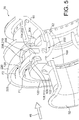
- each injection system 42 generally comprises a sleeve 52, sometimes referred to as a “sliding bushing”, in which a fuel injection nose 54 forming the end of an injector arm 55 is mounted, as well as one or more air intake swirls 56, 58, and finally a bowl 60, sometimes referred to as a “mixing bowl” or “pre-vaporization bowl”, which essentially takes the form of an annular wall having a flared tapered portion downstream.
- a sleeve 52 sometimes referred to as a “sliding bushing”
- a fuel injection nose 54 forming the end of an injector arm 55
- one or more air intake swirls 56, 58 and finally a bowl 60, sometimes referred to as a “mixing bowl” or “pre-vaporization bowl”, which essentially takes the form of an annular wall having a flared tapered portion downstream.
- the air intake tendrils 56, 58 are separated from each other by an annular wall which extends radially inwards to form a annular internal deflection wall 62, also called “venturi”, having an internal profile of convergent-divergent shape.
- the injection systems 42 have an essential role in the operation of the combustion chamber. Their efficiency depends in particular on the quality of their air supply which comes directly from the diffuser.
- the air intake augers 56, 58 contribute to the mixing of air and fuel.
- Each spinner 56, 58 thus comprises an annular row of inclined fins so as to set the air flow 64 in rotation and thus improve the atomization of the fuel jet coming from the fuel injection nose 54.
- some of this fuel trickles in liquid form on the internal surface of the venturi 62 and is sheared by the swirling air at the downstream end of the venturi 62.
- the object of the invention is to improve the performance of the injection systems of turbomachines.
- an injection system for injecting a mixture of air and fuel into a combustion chamber of a turbomachine with an air intake swirl comprising an upstream wall and a downstream wall both of revolution around 'an axis of the air intake swirler, and fins distributed around the axis and connecting the upstream wall to the downstream wall so as to delimit between the upstream and downstream walls air inlet channels having each has an inlet arranged on a radially outer side and an outlet arranged on a radially inner side.
- the air intake swirler further comprises an aerodynamic deflector which extends the downstream wall radially outwards to a free end of the aerodynamic deflector, and which has a concavity facing upstream of so that the aerodynamic deflector extends radially opposite the respective inlets of the air inlet channels.
- the aerodynamic deflector makes it possible to channel the air flow intended to enter the air inlet channels and therefore to limit the pressure losses of this air flow as much as possible.
- the aerodynamic deflector extends continuously over 360 degrees around the axis, from the downstream wall to the free end of the aerodynamic deflector.
- the aerodynamic deflector comprises recesses formed in the free end of the aerodynamic deflector so as to define between them teeth respectively arranged opposite the respective inlets of the air inlet channels. .
- the upstream and downstream walls extend substantially orthogonally to the axis.
- the aerodynamic deflector is preferably shaped so that at each point of the free end of the aerodynamic deflector, a circumferential plane tangent to a radially inner edge of the free end is substantially parallel to the axis of the twist air intake.
- the injection system for injecting a mixture of air and fuel into a combustion chamber of a turbomachine also comprises a sleeve for centering an injector, a bowl, and at least a first spinner. Air intake of the type described above arranged axially between the sleeve and the bowl.
- the injection system further comprises a second air intake swirler also of the type described above, arranged axially between the first air intake swirler and the bowl.
- downstream wall of the first air intake swirler is the upstream wall of the second air intake swirler.
- the injection system advantageously comprises an annular internal deflection wall having an internal profile of converging-diverging shape, which extends the downstream wall of the first air intake swirl towards the interior of the injection system.
- the respective free ends of the respective aerodynamic deflectors of the first and second air intake swirlers extend substantially in the same transverse plane.
- the upstream wall of the first air intake swirler advantageously extends in the same transverse plane.
- the respective free ends of the respective aerodynamic deflectors of the first and second air intake swirlers can be offset with respect to each other in the direction of the axis of the air intake swirler.
- At least one of the respective aerodynamic deflectors of the first and second air intake swirlers is shaped so that the radial extent of the air intake section of the intake swirler d The corresponding air varies around the axis of the air intake swirl.
- the invention also relates to a turbomachine for an aircraft, comprising a combustion chamber and at least one injection system of the type described above for supplying the combustion chamber with a mixture of air and fuel.
- the figures 4 and 5 illustrate an injection system 70 similar to the injection system 42 of the figure 2 described above but comprising two air intake swirls 100, 200.
- the injection system 70 is intended to equip an aircraft turbomachine of the same type as the turbomachine of the figure 1 described above, or any other type of turbomachine.
- the injection system 70 thus comprises a bush 52 intended to receive a fuel injection nozzle, the air intake swirls 100, 200, and a bowl 60.
- the air intake swirls 100, 200 are intended for the injection of a swirling air flow into two internal annular spaces of the injection system separated from each other by an annular internal deflection wall 62 having an internal profile of convergent-divergent shape, also called “venturi”, as explained above in relation to the injection system 42 of known type.
- the first air intake swirl 100 also called an "internal swirl", comprises an upstream wall 102 and a downstream wall 104 which are both of revolution about an axis of the swirler which merges with the axis. injection 44 of the injection system.
- the first air intake swirl 100 further comprises fins 106 distributed around the axis 44 and connecting the upstream wall 102 to the downstream wall 104 so as to define between the upstream and downstream walls air inlet channels 108.
- Each air inlet channel 108 has an inlet 110 arranged on a radially outer side and an outlet 112 arranged on a radially inner side. More precisely, each inlet 110 is delimited between respective radially outer ends of two consecutive fins 106 which delimit the corresponding air inlet channel 108. Similarly, each outlet 112 is delimited between respective radially internal ends of two consecutive fins 106 which delimit the corresponding air inlet channel 108.
- the first air intake swirler 100 further comprises an aerodynamic deflector 120 which extends the downstream wall 104 radially outwards to a free end 122 of the aerodynamic deflector 120.
- the latter has a turned concavity. upstream.
- the aerodynamic deflector 120 thus extends radially opposite the respective inlets 110 of the air inlet channels 108.
- the free end 122 of the aerodynamic deflector 120 is therefore oriented generally in the upstream direction and delimits a section of air inlet of the first air inlet swirl 100.
- the aerodynamic deflector 120 thus makes it possible to channel the air flow F1 entering the air inlet channels 108 and therefore to limit the pressure losses of this air flow as much as possible.
- the aerodynamic deflector 120 extends continuously over 360 degrees around the axis 44, from the downstream wall 104 to the free end 122 of the aerodynamic deflector 120.
- the upstream 102 and downstream 104 walls of the first air intake swirler 100 extend orthogonally to the axis 44.
- the swirler is therefore of the radial type and thus has optimum compactness in the direction. axial.
- upstream 102 and downstream 104 walls can be inclined relative to the axis 44, without departing from the scope of the invention.
- the aerodynamic deflector 120 has a curved shape from the downstream wall 104 and up to the free end 122.
- the aerodynamic deflector 120 can advantageously be manufactured by means of an additive manufacturing process, for example of the selective laser melting (SLM) type.
- SLM selective laser melting
- the aerodynamic deflector 120 may have one or more curved axial sections and one or more cylindrical or frustoconical axial sections arranged axially end-to-end, without departing from the scope of the invention.
- the aerodynamic deflector 120 may consist of a succession of axial sections of frustoconical shape, having respective apex angles that are all the smaller as the axial section considered is away from the downstream wall 104.
- the aerodynamic deflector 120 can have a segmented curvature instead of a continuous curvature, without departing from the scope of the invention.
- the aerodynamic deflector 120 is shaped so that at each point of its free end 122, a circumferential plane P1 tangent to a radially inner edge 124 of the free end 122 is parallel to the axis 44 of the first air intake swirl 100.
- the air intake section of the first air intake swirl 100 is greater than or equal to three times the sum of the respective passage sections of the inlet channels d. air 108 from the first 100 air intake spin.
- At least one of the respective aerodynamic deflectors (120,220) of the first and second air intake swirls (100,200) is shaped so that the radial extent (S1, S2) of the inlet section d
- the air from the corresponding air intake swirl varies around the axis (44).
- the first aerodynamic deflector 120 may have an irregular shape around the axis 44 so as to adapt the radial extent S1 of the air inlet section to the pressure irregularities of the air flow 46 coming from the diffuser. 49 of the turbomachine, as will appear more clearly in what follows.
- the second air intake swirl 200 which is arranged axially between the first air intake swirl 100 and the bowl 60, has a configuration similar to that of the first air intake swirl 100.
- the second air intake swirl 200 also called an “external swirl”, comprises an upstream wall 202, which is the downstream wall 104 of the first air intake swirl 100, and a downstream wall 204
- the two walls 202, 204 are of revolution about the axis of the swirler 200 which merges with the injection axis 44 of the injection system.
- the second air intake swirler 200 further comprises fins 206 distributed around the axis 44 and connecting the upstream wall 202 to the downstream wall 204 so as to delimit between the upstream and downstream walls of the inlet channels d. air 208.
- Each air inlet channel 208 has an inlet 210 arranged on a radially outer side and an outlet 212 arranged on a radially inner side.
- each inlet 210 is delimited between respective radially outer ends of two consecutive fins 206 which delimit the corresponding air inlet channel 208.
- each outlet 212 is delimited between respective radially internal ends of two consecutive fins 206 which delimit the corresponding air inlet channel 208.
- the second air intake swirler 200 comprises an aerodynamic deflector 220 which extends the downstream wall 204 radially outward to a free end 222 of the aerodynamic deflector 220 oriented generally in the upstream direction and delimiting an air inlet section of the second air inlet swirl 200.
- the aerodynamic deflector 220 has characteristics similar to those of the aerodynamic deflector 120 of the first air intake swirl 100 described above, and thus makes it possible to channel the air flow F2 entering the inlet channels of air 208.
- a circumferential plane P2 tangent to a radially inner edge 224 of the free end 222 is parallel to the axis 44 of the second air intake swirl 200 ( figure 4 ).
- the respective free ends 122, 222 of the respective aerodynamic deflectors 120, 220 of the first and second air intake swirlers 100, 200 extend substantially in the same transverse plane P3, in which extends also the upstream wall 102 of the first air intake swirl 100.
- the air intake sections delimited respectively by the aerodynamic deflectors 120 and 220 are defined substantially in the transverse plane P3.
- annular internal deflection wall 62 extends in the extension of the downstream wall 104 of the first air intake swirl 100 towards the interior of the injection system 70.
- FIGS. 6 and 7 illustrate an injection system 70A generally similar to the injection system 70 described above, but in which the first and second air intake swirls 100A, 200A differ from the swirls 100, 200 described above, because that each of their respective aerodynamic deflectors 120A, 220A has recesses 126A, 226A formed in its free end 122A, 222A. These recesses 126A, 226A define between them teeth 128A, 228A respectively arranged facing the respective inlets 110, 210 of the air inlet channels 108, 208.
- the teeth 128A of the aerodynamic deflector 120A of the first air intake swirl 100A are advantageously offset angularly with respect to the teeth 228A of the aerodynamic deflector 220A of the second air intake swirl 200A, so that each tooth 128A or arranged axially facing a corresponding recess 226A.
- the recesses 126A of the aerodynamic deflector 120A of the first air intake swirl 100A thus allow additional air to pass in the direction of the second air intake swirl 200A.
- an injection system according to the invention may comprise a first air intake swirler in accordance with the second embodiment described above and a second air intake swirler in accordance with the first embodiment described. above, or vice versa.
- the figure 8 illustrates an injection system 70B generally similar to the injection system 70 described above, but in which the aerodynamic deflector 220B of the second air intake swirl 200B is shaped so that the radial extent S2 of the air inlet section of said air intake swirl 200B varies around the axis 44.
- the aerodynamic deflector 220B is in particular shaped so that its free end 222B is circular in shape and is eccentric with respect to the axis 44.
- the free end 222B is for example eccentric from the axis 44 in a direction oriented radially. outwards in relation to axis 28 of the combustion chamber (visible on the figure 2 ).
- the radial extent S2 preferably takes a minimum value S2min equal to half of a nominal value corresponding to the radial extent that an equivalent section but of constant radial extent would have (as in the figures 4 and 5 ).
- the radial extent S2 preferably takes a maximum value S2max equal to three times the nominal value.
- the variability of the radial extent S2 of the air inlet section can be obtained by a non-axisymmetric shape of the aerodynamic deflector 220B, for example an eccentric oval shape.
- the aerodynamic deflector of the first air intake swirler can adopt a configuration such that the radial extent S1 of the air inlet section of the first air intake swirler varies around axis 44.
- the variability of the radial extent of the air inlet section of at least one of the air inlet swirlers makes it possible to optimize the homogeneity of the air supply of the air inlet.
- this spin having regard to various design parameters of the turbomachine, including in particular the possible heterogeneity of the flow at the outlet of compressor 16, the wake induced by the injector arm 55 in the air flow supplying the system d injection 70B, and the influence of the protective annular fairing 45 on the aforementioned air flow.
- the figures 9 and 10 respectively illustrate injection systems 70C and 70D generally similar to the injection system 70 described above, but in which the respective free ends of the respective aerodynamic deflectors of the first and second air intake swirlers are offset one by one with respect to the other in the direction of axis 44.
- the aerodynamic deflector 120C of the first air intake swirl 100C extends upstream beyond the free end 222 of the aerodynamic deflector 220 of the second air intake swirl 200.
- the aerodynamic baffle 220D of the second air intake twist 200D extends upstream beyond the free end 122 of the aerodynamic baffle 120 of the first air intake twist 100.
- the figure 11 illustrates a 70E injection system similar to that of the figure 10 , except in that the aerodynamic deflector 220E of the second air intake swirl 200E has an oval or oblong free end 222E, extending for example from an annular portion of circular section 223E of the deflector.
- the major axis 230E of the free end 222E is oriented in a circumferential direction defined with respect to the axis 28 of the combustion chamber (visible on the figure 2 ).
- the shape of the free end 222E provides variability in the radial extent of the air inlet section of the second air inlet swirl 200E around axis 44, similarly to what has been described with reference to the figure 8 .
Description
La présente invention concerne une vrille d'admission d'air destinée à faire partie d'un système d'injection d'air et de carburant dans une turbomachine, ainsi qu'un système d'injection pour turbomachine comprenant au moins une telle vrille d'admission d'air, et une turbomachine pour aéronef comprenant un tel système d'injection.The present invention relates to an air intake swirler intended to form part of an air and fuel injection system in a turbomachine, as well as an injection system for a turbomachine comprising at least one such swirler. air intake, and a turbomachine for an aircraft comprising such an injection system.
Le document
La
La chambre de combustion comporte en général un carénage annulaire de protection 45 s'étendant en regard d'une face amont de la paroi de fond de chambre 40 et comportant des orifices de passage d'injecteurs et d'admission d'air.The combustion chamber generally comprises an annular
En fonctionnement, une partie 46 d'un flux d'air 48 issu d'un diffuseur 49 et provenant du compresseur 16 alimente les systèmes d'injection 42 tandis qu'une autre partie 50 de ce flux d'air contourne la chambre de combustion en s'écoulant vers l'aval le long des parois coaxiales 32 et 34 de cette chambre et permet notamment l'alimentation d'orifices d'entrée d'air prévus au sein de ces parois 32 et 34.In operation, a
Comme le montre la
Les vrilles d'admission d'air 56, 58 (également dénommées « swirlers » d'après la terminologie anglo-saxonne) sont séparées l'une de l'autre par une paroi annulaire qui se prolonge radialement vers l'intérieur pour former une paroi annulaire de déflection interne 62, également dénommée « venturi », ayant un profil interne de forme convergente-divergente.The
Les systèmes d'injection 42 ont un rôle essentiel dans le fonctionnement de la chambre de combustion. Leur efficacité dépend notamment de la qualité de leur alimentation en air qui provient directement du diffuseur.The
À cet égard, les vrilles d'admission d'air 56, 58 contribuent au mélange de l'air et du carburant. Chaque vrille 56, 58 comporte ainsi une rangée annulaire d'ailettes inclinées de manière à mettre en rotation l'écoulement d'air 64 et améliorer ainsi l'atomisation du jet de carburant provenant du nez d'injection de carburant 54. En particulier, une partie de ce carburant ruisselle sous forme liquide sur la surface interne du venturi 62 et est cisaillé par l'air tourbillonnant au niveau de l'extrémité aval du venturi 62.In this regard, the
L'invention a pour but d'améliorer les performances des systèmes d'injection des turbomachines.The object of the invention is to improve the performance of the injection systems of turbomachines.
Elle propose à cet effet un système d'injection pour injecter un mélange d'air et de carburant dans une chambre de combustion de turbomachine avec une vrille d'admission d'air comprenant une paroi amont et une paroi aval toutes deux de révolution autour d'un axe de la vrille d'admission d'air, et des ailettes réparties autour de l'axe et reliant la paroi amont à la paroi aval de manière à délimiter entre les parois amont et aval des canaux d'entrée d'air présentant chacun une entrée agencée d'un côté radialement externe et une sortie agencée d'un côté radialement interne.It provides for this purpose an injection system for injecting a mixture of air and fuel into a combustion chamber of a turbomachine with an air intake swirl comprising an upstream wall and a downstream wall both of revolution around 'an axis of the air intake swirler, and fins distributed around the axis and connecting the upstream wall to the downstream wall so as to delimit between the upstream and downstream walls air inlet channels having each has an inlet arranged on a radially outer side and an outlet arranged on a radially inner side.
Selon l'invention, la vrille d'admission d'air comporte en outre un déflecteur aérodynamique qui prolonge la paroi aval radialement vers l'extérieur jusqu'à une extrémité libre du déflecteur aérodynamique, et qui présente une concavité tournée vers l'amont de sorte que le déflecteur aérodynamique s'étend en regard radialement des entrées respectives des canaux d'entrée d'air.According to the invention, the air intake swirler further comprises an aerodynamic deflector which extends the downstream wall radially outwards to a free end of the aerodynamic deflector, and which has a concavity facing upstream of so that the aerodynamic deflector extends radially opposite the respective inlets of the air inlet channels.
D'une manière générale, le déflecteur aérodynamique permet de canaliser le flux d'air destiné à entrer dans les canaux d'entrée d'air et donc de limiter au mieux les pertes de charges de ce flux d'air.In general, the aerodynamic deflector makes it possible to channel the air flow intended to enter the air inlet channels and therefore to limit the pressure losses of this air flow as much as possible.
Il en résulte une amélioration des performances générales d'une chambre de combustion de turbomachine équipée d'un système d'injection comprenant une telle vrille d'admission d'air, en particulier en termes de cycle thermodynamique global.This results in an improvement in the general performance of a turbomachine combustion chamber equipped with an injection system comprising such an air intake swirler, in particular in terms of the overall thermodynamic cycle.
Dans un premier mode de réalisation préféré de l'invention, le déflecteur aérodynamique s'étend continument sur 360 degrés autour de l'axe, depuis la paroi aval jusqu'à l'extrémité libre du déflecteur aérodynamique.In a first preferred embodiment of the invention, the aerodynamic deflector extends continuously over 360 degrees around the axis, from the downstream wall to the free end of the aerodynamic deflector.
Dans un deuxième mode de réalisation préféré de l'invention, le déflecteur aérodynamique comporte des évidements formés dans l'extrémité libre du déflecteur aérodynamique de manière à délimiter entre eux des dents respectivement agencées en regard des entrées respectives des canaux d'entrée d'air.In a second preferred embodiment of the invention, the aerodynamic deflector comprises recesses formed in the free end of the aerodynamic deflector so as to define between them teeth respectively arranged opposite the respective inlets of the air inlet channels. .
De préférence, les parois amont et aval s'étendent sensiblement orthogonalement à l'axe.Preferably, the upstream and downstream walls extend substantially orthogonally to the axis.
Par ailleurs, le déflecteur aérodynamique est de préférence conformé de sorte qu'en chaque point de l'extrémité libre du déflecteur aérodynamique, un plan circonférentiel tangent à un bord radialement interne de l'extrémité libre est sensiblement parallèle à l'axe de la vrille d'admission d'air.Furthermore, the aerodynamic deflector is preferably shaped so that at each point of the free end of the aerodynamic deflector, a circumferential plane tangent to a radially inner edge of the free end is substantially parallel to the axis of the twist air intake.
Selon l'invention, le système d'injection pour injecter un mélange d'air et de carburant dans une chambre de combustion de turbomachine, comprend également une douille pour le centrage d'un injecteur, un bol, et au moins une première vrille d'admission d'air du type décrit ci-dessus agencée axialement entre la douille et le bol.According to the invention, the injection system for injecting a mixture of air and fuel into a combustion chamber of a turbomachine, also comprises a sleeve for centering an injector, a bowl, and at least a first spinner. Air intake of the type described above arranged axially between the sleeve and the bowl.
Selon l'invention, le système d'injection comprend en outre une deuxième vrille d'admission d'air également du type décrit ci-dessus, agencée axialement entre la première vrille d'admission d'air et le bol.According to the invention, the injection system further comprises a second air intake swirler also of the type described above, arranged axially between the first air intake swirler and the bowl.
Dans ce cas, la paroi aval de la première vrille d'admission d'air est la paroi amont de la deuxième vrille d'admission d'air.In this case, the downstream wall of the first air intake swirler is the upstream wall of the second air intake swirler.
De plus, le système d'injection comprend avantageusement une paroi annulaire de déflection interne ayant un profil interne de forme convergente-divergente, qui prolonge la paroi aval de la première vrille d'admission d'air vers l'intérieur du système d'injection.In addition, the injection system advantageously comprises an annular internal deflection wall having an internal profile of converging-diverging shape, which extends the downstream wall of the first air intake swirl towards the interior of the injection system. .
De préférence, les extrémités libres respectives des déflecteurs aérodynamiques respectifs des première et deuxième vrilles d'admission d'air s'étendent sensiblement dans un même plan transversal.Preferably, the respective free ends of the respective aerodynamic deflectors of the first and second air intake swirlers extend substantially in the same transverse plane.
Dans ce cas, la paroi amont de la première vrille d'admission d'air s'étend avantageusement dans le même plan transversal.In this case, the upstream wall of the first air intake swirler advantageously extends in the same transverse plane.
En variante, les extrémités libres respectives des déflecteurs aérodynamiques respectifs des première et deuxième vrilles d'admission d'air peuvent être décalées l'une par rapport à l'autre selon la direction de l'axe de la vrille d'admission d'air.As a variant, the respective free ends of the respective aerodynamic deflectors of the first and second air intake swirlers can be offset with respect to each other in the direction of the axis of the air intake swirler. .
Selon l'invention, l'un au moins des déflecteurs aérodynamiques respectifs des première et deuxième vrilles d'admission d'air est conformé de sorte que l'étendue radiale de la section d'entrée d'air de la vrille d'admission d'air correspondante varie autour de l'axe de la vrille d'admission d'air.According to the invention, at least one of the respective aerodynamic deflectors of the first and second air intake swirlers is shaped so that the radial extent of the air intake section of the intake swirler d The corresponding air varies around the axis of the air intake swirl.
L'invention concerne encore une turbomachine pour aéronef, comprenant une chambre de combustion et au moins un système d'injection du type décrit ci-dessus pour alimenter la chambre de combustion en un mélange d'air et de carburant.The invention also relates to a turbomachine for an aircraft, comprising a combustion chamber and at least one injection system of the type described above for supplying the combustion chamber with a mixture of air and fuel.
L'invention sera mieux comprise, et d'autres détails, avantages et caractéristiques de celle-ci apparaîtront à la lecture de la description suivante faite à titre d'exemple non limitatif et en référence aux dessins annexés dans lesquels :
- la
figure 1 , déjà décrite, est une vue schématique en section axiale d'une turbomachine d'un type connu ; - la
figure 2 , déjà décrite, est une demi-vue schématique en section axiale d'une chambre de combustion de la turbomachine de lafigure 1 ; - la
figure 3 , déjà décrite, est une vue schématique en section axiale d'un système d'injection de la chambre de combustion de lafigure 2 ; - la
figure 4 est une demi-vue schématique en section axiale d'un système d'injection qui ne fait pas partie de l'invention ; - la
figure 5 est une vue schématique partielle en perspective et en section axiale du système d'injection de lafigure 4 ; - les
figures 6 et7 sont des vue schématiques, respectivement en perspective et de face, d'un système d'injection qui ne fait pas partie de l'invention ; - les
figures 8 à 11 sont des vue schématiques en perspective de systèmes d'injection selon l'invention.
- the
figure 1 , already described, is a schematic view in axial section of a turbomachine of a known type; - the
figure 2 , already described, is a schematic half-view in axial section of a combustion chamber of the turbomachine of thefigure 1 ; - the
figure 3 , already described, is a schematic view in axial section of an injection system of the combustion chamber of thefigure 2 ; - the
figure 4 is a schematic half-view in axial section of an injection system which does not form part of the invention; - the
figure 5 is a partial schematic view in perspective and in axial section of the injection system of thefigure 4 ; - the
figures 6 and7 are schematic views, respectively in perspective and from the front, of an injection system which does not form part of the invention; - the
figures 8 to 11 are schematic perspective views of injection systems according to the invention.
Dans l'ensemble de ces figures, des références identiques peuvent désigner des éléments identiques ou analogues.In all of these figures, identical references can designate identical or similar elements.
Les
Le système d'injection 70 comprend ainsi une douille 52 destinée à recevoir un nez d'injection de carburant, les vrilles d'admission d'air 100, 200, et un bol 60. Les vrilles d'admission d'air 100, 200 sont destinées à l'injection d'un flux d'air tourbillonnant dans deux espaces annulaires internes du système d'injection séparés l'un de l'autre par une paroi annulaire de déflection interne 62 ayant un profil interne de forme convergente-divergente, également dénommée « venturi », comme expliqué ci-dessus en relation avec le système d'injection 42 de type connu.The
La première vrille d'admission d'air 100, également dénommée « vrille interne », comporte une paroi amont 102 et une paroi aval 104 qui sont toutes les deux de révolution autour d'un axe de la vrille qui se confond avec l'axe d'injection 44 du système d'injection. La première vrille d'admission d'air 100 comporte en outre des ailettes 106 réparties autour de l'axe 44 et reliant la paroi amont 102 à la paroi aval 104 de manière à délimiter entre les parois amont et aval des canaux d'entrée d'air 108. Chaque canal d'entrée d'air 108 présente une entrée 110 agencée d'un côté radialement externe et une sortie 112 agencée d'un côté radialement interne. Plus précisément, chaque entrée 110 est délimitée entre des extrémités radialement externes respectives des deux ailettes 106 consécutives qui délimitent le canal d'entrée d'air 108 correspondant. De manière analogue, chaque sortie 112 est délimitée entre des extrémités radialement internes respectives des deux ailettes 106 consécutives qui délimitent le canal d'entrée d'air 108 correspondant.The first
Selon cet exemple, la première vrille d'admission d'air 100 comporte en outre un déflecteur aérodynamique 120 qui prolonge la paroi aval 104 radialement vers l'extérieur jusqu'à une extrémité libre 122 du déflecteur aérodynamique 120. Ce dernier présente une concavité tournée vers l'amont. Le déflecteur aérodynamique 120 s'étend ainsi en regard radialement des entrées 110 respectives des canaux d'entrée d'air 108. L'extrémité libre 122 du déflecteur aérodynamique 120 est donc orientée globalement en direction de l'amont et délimite une section d'entrée d'air de la première vrille d'admission d'air 100.According to this example, the first
D'une manière générale, le déflecteur aérodynamique 120 permet ainsi de canaliser le flux d'air F1 entrant dans les canaux d'entrée d'air 108 et donc de limiter au mieux les pertes de charges de ce flux d'air.In general, the
Dans le système illustré sur les
Dans l'exemple illustré, les parois amont 102 et aval 104 de la première vrille d'admission d'air 100 s'étendent orthogonalement à l'axe 44. La vrille est donc du type radial et présente ainsi une compacité optimale selon la direction axiale.In the example illustrated, the upstream 102 and downstream 104 walls of the first
En variante, les parois amont 102 et aval 104 peuvent être inclinées par rapport à l'axe 44, sans sortir du cadre de l'invention.As a variant, the upstream 102 and downstream 104 walls can be inclined relative to the
De plus, dans l'exemple illustré, le déflecteur aérodynamique 120 présente une forme incurvée à partir de la paroi aval 104 et jusqu'à l'extrémité libre 122.In addition, in the example illustrated, the
Le déflecteur aérodynamique 120 peut être avantageusement fabriqué au moyen d'un procédé de fabrication additive, par exemple du type fusion sélective par laser (SLM). The
En variante, le déflecteur aérodynamique 120 peut présenter une ou plusieurs sections axiales incurvées et une ou plusieurs sections axiales cylindriques ou tronconiques agencées axialement bout-à-bout, sans sortir du cadre de l'invention.As a variant, the
En variante encore, le déflecteur aérodynamique 120 peut être constitué d'une succession de sections axiales de forme tronconique, ayant des angles au sommet respectifs d'autant plus petits que la section axiale considérée est éloignée de la paroi aval 104. Autrement dit, le déflecteur aérodynamique 120 peut présenter une courbure segmentée au lieu d'une courbure continue, sans sortir du cadre de l'invention.As a further variant, the
Par ailleurs, dans l'exemple illustré, le déflecteur aérodynamique 120 est conformé de sorte qu'en chaque point de son extrémité libre 122, un plan circonférentiel P1 tangent à un bord radialement interne 124 de l'extrémité libre 122 est parallèle à l'axe 44 de la première vrille d'admission d'air 100.Furthermore, in the example illustrated, the
Dans des modes de réalisation préférés de l'invention, la section d'entrée d'air de la première vrille d'admission d'air 100 est supérieure ou égale au triple de la somme de sections de passage respectives des canaux d'entrée d'air 108 de la première vrille d'admission d'air 100.In preferred embodiments of the invention, the air intake section of the first
Selon l'invention, un au moins des déflecteurs aérodynamiques (120,220) respectifs des première et deuxième vrilles d'admission d'air (100,200) est conformé de sorte que l'étendue radiale (S1,S2) de la section d'entrée d'air de la vrille d'admission d'air correspondante varie autour de l'axe (44). En variante, le premier déflecteur aérodynamique 120 peut présenter une forme irrégulière autour de l'axe 44 de manière à adapter l'étendue radiale S1 de la section d'entrée d'air aux irrégularités de pression du flux d'air 46 issu du diffuseur 49 de la turbomachine, comme cela apparaîtra plus clairement dans ce qui suit.According to the invention, at least one of the respective aerodynamic deflectors (120,220) of the first and second air intake swirls (100,200) is shaped so that the radial extent (S1, S2) of the inlet section d The air from the corresponding air intake swirl varies around the axis (44). As a variant, the first
La deuxième vrille d'admission d'air 200, qui est agencée axialement entre la première vrille d'admission d'air 100 et le bol 60, présente une configuration analogue à celle de la première vrille d'admission d'air 100.The second
En particulier, la deuxième vrille d'admission d'air 200, également dénommée « vrille externe », comporte une paroi amont 202, qui est la paroi aval 104 de la première vrille d'admission d'air 100, et une paroi aval 204. Les deux parois 202, 204 sont de révolution autour de l'axe de la vrille 200 qui se confond avec l'axe d'injection 44 du système d'injection. La deuxième vrille d'admission d'air 200 comporte en outre des ailettes 206 réparties autour de l'axe 44 et reliant la paroi amont 202 à la paroi aval 204 de manière à délimiter entre les parois amont et aval des canaux d'entrée d'air 208. Chaque canal d'entrée d'air 208 présente une entrée 210 agencée d'un côté radialement externe et une sortie 212 agencée d'un côté radialement interne. Plus précisément, chaque entrée 210 est délimitée entre des extrémités radialement externes respectives des deux ailettes 206 consécutives qui délimitent le canal d'entrée d'air 208 correspondant. De manière analogue, chaque sortie 212 est délimitée entre des extrémités radialement internes respectives des deux ailettes 206 consécutives qui délimitent le canal d'entrée d'air 208 correspondant.In particular, the second
De plus, la deuxième vrille d'admission d'air 200 comporte un déflecteur aérodynamique 220 qui prolonge la paroi aval 204 radialement vers l'extérieur jusqu'à une extrémité libre 222 du déflecteur aérodynamique 220 orientée globalement en direction de l'amont et délimitant une section d'entrée d'air de la deuxième vrille d'admission d'air 200.In addition, the second
Le déflecteur aérodynamique 220 présente des caractéristiques analogues à celles du déflecteur aérodynamique 120 de la première vrille d'admission d'air 100 décrit ci-dessus, et permet ainsi de canaliser le flux d'air F2 entrant dans les canaux d'entrée d'air 208.The
En particulier, un plan circonférentiel P2 tangent à un bord radialement interne 224 de l'extrémité libre 222 est parallèle à l'axe 44 de la deuxième vrille d'admission d'air 200 (
Dans l'exemple illustré, les extrémités libres 122, 222 respectives des déflecteurs aérodynamiques 120, 220 respectifs des première et deuxième vrilles d'admission d'air 100, 200 s'étendent sensiblement dans un même plan transversal P3, dans lequel s'étend également la paroi amont 102 de la première vrille d'admission d'air 100. Ainsi, les sections d'entrées d'air délimitées respectivement par les déflecteurs aérodynamiques 120 et 220 sont définies sensiblement dans le plan transversal P3.In the example illustrated, the respective free ends 122, 222 of the respective
Par ailleurs, la paroi annulaire de déflection interne 62 s'étend dans le prolongement de la paroi aval 104 de la première vrille d'admission d'air 100 vers l'intérieur du système d'injection 70.Furthermore, the annular
Les
Les dents 128A du déflecteur aérodynamique 120A de la première vrille d'admission d'air 100A sont avantageusement décalées angulairement par rapport aux dents 228A du déflecteur aérodynamique 220A de la deuxième vrille d'admission d'air 200A, de telle sorte que chaque dent 128A soit agencée en regard axialement d'un évidement 226A correspondant.The
Les évidements 126A du déflecteur aérodynamique 120A de la première vrille d'admission d'air 100A permettent ainsi de laisser passer un surcroît d'air en direction de la deuxième vrille d'admission d'air 200A.The
En variante, un système d'injection selon l'invention peut comporter une première vrille d'admission d'air conforme au deuxième mode de réalisation décrit ci-dessus et une deuxième vrille d'admission d'air conforme au premier mode de réalisation décrit ci-dessus, ou l'inverse.As a variant, an injection system according to the invention may comprise a first air intake swirler in accordance with the second embodiment described above and a second air intake swirler in accordance with the first embodiment described. above, or vice versa.
La
Dans l'exemple illustré sur la
L'étendue radiale S2 prend de préférence une valeur minimale S2min égale à la moitié d'une valeur nominale correspondant à l'étendue radiale qu'aurait une section équivalente mais d'étendue radiale constante (comme sur les
En variante, la variabilité de l'étendue radiale S2 de la section d'entrée d'air peut être obtenue par une forme non axisymétrique du déflecteur aérodynamique 220B, par exemple une forme ovale excentrée.As a variant, the variability of the radial extent S2 of the air inlet section can be obtained by a non-axisymmetric shape of the
En variante ou de manière complémentaire, le déflecteur aérodynamique de la première vrille d'admission d'air peut adopter une configuration telle que l'étendue radiale S1 de la section d'entrée d'air de la première vrille d'admission d'air varie autour de l'axe 44.As a variant or in a complementary manner, the aerodynamic deflector of the first air intake swirler can adopt a configuration such that the radial extent S1 of the air inlet section of the first air intake swirler varies around
D'une manière générale, la variabilité de l'étendue radiale de la section d'entrée d'air de l'une au moins des vrilles d'admission d'air permet d'optimiser l'homogénéité de l'alimentation en air de cette vrille eu égard à divers paramètres de conception de la turbomachine, dont en particulier l'hétérogénéité éventuelle de l'écoulement en sortie de compresseur 16, le sillage induit par le bras d'injecteur 55 dans le flux d'air alimentant le système d'injection 70B, et l'influence du carénage annulaire de protection 45 sur le flux d'air précité.In general, the variability of the radial extent of the air inlet section of at least one of the air inlet swirlers makes it possible to optimize the homogeneity of the air supply of the air inlet. this spin having regard to various design parameters of the turbomachine, including in particular the possible heterogeneity of the flow at the outlet of
D'autres variantes permettent d'optimiser l'alimentation en air des vrilles d'admission d'air en fonction de tels paramètres, comme le montrent les
Les
Ainsi, dans le mode de réalisation de la
À l'inverse, dans le mode de réalisation de la
Enfin, la
Dans l'exemple illustré, le grand-axe 230E de l'extrémité libre 222E est orienté selon une direction circonférentielle définie par rapport à l'axe 28 de la chambre de combustion (visible sur la
La forme de l'extrémité libre 222E permet d'obtenir une variabilité de l'étendue radiale de la section d'entrée d'air de la deuxième vrille d'admission d'air 200E autour de l'axe 44, de manière analogue à ce qui a été décrit en référence à la
Claims (12)
- An injection system (70; 70A; 70B; 70C; 70D; 70E) for injecting an air and fuel mixture in a turbomachine combustion chamber, comprising a sleeve (52) for centring an injector, a bowl (60), a first air intake swirler (100; 100A; 100C) axially arranged between the sleeve (52) and the bowl (60), and a second air intake swirler (200; 200A; 200B; 200D; 200E) axially arranged between the first air intake swirler (100; 100A; 100C) and the bowl (60), each of the air intake swirlers comprising an upstream wall (102, 202) and a downstream wall (104, 204) both of revolution about an axis (44) of the air intake swirler, and fins (106, 206) distributed about the axis (44) and connecting the upstream wall to the downstream wall so as to delimit between the downstream and upstream walls air inlet channels (108, 208) each having an inlet (110, 210) arranged on a radially outer side and an outlet (112, 212) arranged on a radially inner side, wherein the downstream wall (104) of the first air intake swirler (100; 100A; 100C) is the upstream wall (202) of the second air intake swirler (200; 200A; 200B; 200D; 200E), characterised in that each of the air intake swirlers further includes a respective aerodynamic deflector (120, 220; 120A, 220A; 120, 220B; 120C, 220; 120, 220D; 120, 220E) which is an outwardly radial extension of the downstream wall (104, 204) of the corresponding air intake swirler and is terminated with a free end (122, 222; 122A, 222A; 122, 222B; 122, 222E), wherein each respective aerodynamic deflector has a concavity pointing upstream such that the aerodynamic deflector extends radially facing the respective inlets (110, 210) of the air inlet channels of the corresponding air intake swirler, wherein at least one of the respective aerodynamic deflectors (220B; 220E) of the first and second air intake swirlers is shaped such that the radial extent (S2) of the air inlet section of the corresponding air intake swirler (200B; 200E) varies about the axis (44).
- The injection system according to claim 1, wherein the aerodynamic deflector (120, 220; 120, 220B; 120C , 220; 120, 220D; 120, 220E) of at least one of the first and second air intake swirlers (100, 200; 100, 200B; 100C, 200; 100, 200D; 100, 200E) continuously extends over 360 degrees about the axis (44), from the downstream wall (104, 204) to the free end (122, 222; 122, 222B; 122, 222E) of the aerodynamic deflector.
- The injection system according to claim 1, wherein the aerodynamic deflector (120A, 220A) of at least one of the first and second air intake swirlers (100A, 200A) includes recesses (126A, 226A) formed in the free end (122A, 222A) of the aerodynamic deflector so as to delimit between them teeth (128A, 228A) respectively arranged facing the respective inlets (110, 210) of the air inlet channels of the corresponding air intake swirler (100A, 200A).
- The injection system according to any of claims 1 to 3, wherein the upstream (102, 202) and downstream (104, 204) walls of each of the first and second air intake swirlers (100, 200; 100A, 200A; 100, 200B; 100C, 200; 100, 200D; 100, 200E) substantially extend orthogonally to the axis (44).
- The injection system according to any of claims 1 to 4, wherein the aerodynamic deflector (120, 220; 120A, 220A; 120, 220B; 120C, 220; 120, 220D; 120, 220E) of each of the first and second air intake swirlers (100, 200; 100A, 200A; 100, 200B; 100C, 200; 100, 200D; 100, 200E) is shaped such that at each point of the free end (122, 222) of the aerodynamic deflector, a circumferential plane (P1, P2) tangent to a radially inner edge (124, 224) of the free end is substantially parallel to the axis (44).
- The injection system according to any of claims 1 to 5, further comprising an inner deflection annular wall (62) having an inner profile with a convergent-divergent shape, which is an extension of the downstream wall (104) of the first air intake swirler inwardly of the injection system.
- The injection system according to any of claims 1 to 6, wherein the respective free ends (122, 222; 122A, 222A; 122, 222B) of the respective aerodynamic deflectors (120, 220; 120A, 220A; 120, 220B) of the first and second air intake swirlers (100, 200; 100A, 200A; 100, 200B) substantially extend in a same transverse plane (P3).
- The injection system according to claim 7, wherein the upstream wall (102) of the first air intake swirler (100; 100A) extends in the same transverse plane (P3).
- The injection system according to any of claims 1 to 6, wherein the respective free ends (122, 222) of the respective aerodynamic deflectors (120C, 220; 120, 220D) of the first and second air intake swirlers (100C, 200; 100, 200D) are offset with respect to each other along the direction of the axis (44).
- The injection system according to any of claims 1 to 9, wherein said aerodynamic deflector (220B; 220E), which is shaped such that the radial extent (S2) of the air inlet section of the corresponding air intake swirler (200B; 200E) varies about the axis (44), is shaped so that its free end (222B; 222E) is off-centred from the axis 44.
- The injection system according to any of claims 1 to 10, wherein said aerodynamic deflector (220B; 220E), which is shaped such that the radial extent (S2) of the air inlet section of the corresponding air intake swirler (200B; 200E) varies about the axis (44), has a non-axisymmetric shape.
- An aircraft turbomachine, comprising a combustion chamber and at least one injection system (70, 70A) according to any of claims 1 to 11 for supplying the combustion chamber with an air and fuel mixture.
Applications Claiming Priority (2)
| Application Number | Priority Date | Filing Date | Title |
|---|---|---|---|
| FR1653828A FR3050806B1 (en) | 2016-04-28 | 2016-04-28 | AIR INTAKE BALL FOR A TURBOMACHINE INJECTION SYSTEM COMPRISING AN AERODYNAMIC DEFLECTOR AT ITS INPUT |
| PCT/FR2017/051017 WO2017187104A1 (en) | 2016-04-28 | 2017-04-28 | Air intake swirler for a turbomachine injection system comprising an aerodynamic deflector at its inlet |
Publications (2)
| Publication Number | Publication Date |
|---|---|
| EP3449185A1 EP3449185A1 (en) | 2019-03-06 |
| EP3449185B1 true EP3449185B1 (en) | 2021-08-04 |
Family
ID=56148528
Family Applications (1)
| Application Number | Title | Priority Date | Filing Date |
|---|---|---|---|
| EP17725689.8A Active EP3449185B1 (en) | 2016-04-28 | 2017-04-28 | Turbomachine injection system comprising an aerodynamic deflector at its inlet and an air intake swirler |
Country Status (5)
| Country | Link |
|---|---|
| US (1) | US10883718B2 (en) |
| EP (1) | EP3449185B1 (en) |
| CN (1) | CN109073224B (en) |
| FR (1) | FR3050806B1 (en) |
| WO (1) | WO2017187104A1 (en) |
Families Citing this family (1)
| Publication number | Priority date | Publication date | Assignee | Title |
|---|---|---|---|---|
| FR3096114B1 (en) | 2019-05-13 | 2022-10-28 | Safran Aircraft Engines | Combustion chamber comprising means for cooling an annular envelope zone downstream of a stack |
Citations (2)
| Publication number | Priority date | Publication date | Assignee | Title |
|---|---|---|---|---|
| US2958195A (en) * | 1959-02-25 | 1960-11-01 | Philip G Dooley | Air inlet construction |
| WO2010081940A1 (en) * | 2009-01-16 | 2010-07-22 | Snecma | Device for injecting an air and fuel mixture in the combustion chamber of a turbine engine |
Family Cites Families (23)
| Publication number | Priority date | Publication date | Assignee | Title |
|---|---|---|---|---|
| US3648457A (en) * | 1970-04-30 | 1972-03-14 | Gen Electric | Combustion apparatus |
| GB1421399A (en) * | 1972-11-13 | 1976-01-14 | Snecma | Fuel injectors |
| FR2235274B1 (en) * | 1973-06-28 | 1976-09-17 | Snecma | |
| US3946552A (en) * | 1973-09-10 | 1976-03-30 | General Electric Company | Fuel injection apparatus |
| US3972182A (en) * | 1973-09-10 | 1976-08-03 | General Electric Company | Fuel injection apparatus |
| DE4110507C2 (en) * | 1991-03-30 | 1994-04-07 | Mtu Muenchen Gmbh | Burner for gas turbine engines with at least one swirl device which can be regulated in a load-dependent manner for the supply of combustion air |
| EP0678708B1 (en) | 1994-04-20 | 1998-12-02 | ROLLS-ROYCE plc | Gas turbine engine fuel injector |
| US6550251B1 (en) * | 1997-12-18 | 2003-04-22 | General Electric Company | Venturiless swirl cup |
| US6272865B1 (en) * | 1999-04-30 | 2001-08-14 | United Technologies Corporation | Swirler scoop and bearing plate for combustor |
| US6883332B2 (en) | 1999-05-07 | 2005-04-26 | Parker-Hannifin Corporation | Fuel nozzle for turbine combustion engines having aerodynamic turning vanes |
| GB0219461D0 (en) | 2002-08-21 | 2002-09-25 | Rolls Royce Plc | Fuel injection arrangement |
| FR2903171B1 (en) * | 2006-06-29 | 2008-10-17 | Snecma Sa | CRABOT LINK ARRANGEMENT FOR TURBOMACHINE COMBUSTION CHAMBER |
| JP4421620B2 (en) * | 2007-02-15 | 2010-02-24 | 川崎重工業株式会社 | Gas turbine engine combustor |
| US8806871B2 (en) * | 2008-04-11 | 2014-08-19 | General Electric Company | Fuel nozzle |
| GB0916944D0 (en) | 2009-09-28 | 2009-11-11 | Rolls Royce Plc | Air blast fuel injector |
| FR2975467B1 (en) * | 2011-05-17 | 2013-11-08 | Snecma | FUEL INJECTION SYSTEM FOR A TURBOMACHINE COMBUSTION CHAMBER |
| GB201112434D0 (en) | 2011-07-20 | 2011-08-31 | Rolls Royce Plc | A fuel injector |
| GB201315008D0 (en) | 2013-08-22 | 2013-10-02 | Rolls Royce Plc | Airblast fuel injector |
| EP2944792A1 (en) * | 2014-05-12 | 2015-11-18 | Siemens Aktiengesellschaft | Method for operation a burner and combustion system |
| CN204084467U (en) * | 2014-09-22 | 2015-01-07 | 北京华清燃气轮机与煤气化联合循环工程技术有限公司 | The swirl nozzle that the axial two-stage direction of gas-turbine combustion chamber is contrary |
| US10317083B2 (en) * | 2014-10-03 | 2019-06-11 | Pratt & Whitney Canada Corp. | Fuel nozzle |
| US9927126B2 (en) * | 2015-06-10 | 2018-03-27 | General Electric Company | Prefilming air blast (PAB) pilot for low emissions combustors |
| US20160377293A1 (en) * | 2015-06-25 | 2016-12-29 | Delavan Inc | Fuel injector systems |
-
2016
- 2016-04-28 FR FR1653828A patent/FR3050806B1/en active Active
-
2017
- 2017-04-28 WO PCT/FR2017/051017 patent/WO2017187104A1/en active Application Filing
- 2017-04-28 US US16/095,813 patent/US10883718B2/en active Active
- 2017-04-28 CN CN201780025996.3A patent/CN109073224B/en active Active
- 2017-04-28 EP EP17725689.8A patent/EP3449185B1/en active Active
Patent Citations (2)
| Publication number | Priority date | Publication date | Assignee | Title |
|---|---|---|---|---|
| US2958195A (en) * | 1959-02-25 | 1960-11-01 | Philip G Dooley | Air inlet construction |
| WO2010081940A1 (en) * | 2009-01-16 | 2010-07-22 | Snecma | Device for injecting an air and fuel mixture in the combustion chamber of a turbine engine |
Also Published As
| Publication number | Publication date |
|---|---|
| US10883718B2 (en) | 2021-01-05 |
| WO2017187104A1 (en) | 2017-11-02 |
| FR3050806B1 (en) | 2020-02-21 |
| CN109073224B (en) | 2021-02-05 |
| EP3449185A1 (en) | 2019-03-06 |
| US20200033007A1 (en) | 2020-01-30 |
| FR3050806A1 (en) | 2017-11-03 |
| CN109073224A (en) | 2018-12-21 |
Similar Documents
| Publication | Publication Date | Title |
|---|---|---|
| EP1688588B1 (en) | Diffusor for an annular combustor, as well as combustor and turboprop with such a diffusor | |
| CA2835361C (en) | Annular combustion chamber for a turbomachine | |
| CA2750856C (en) | Diffuser/rectifier assembly for a turbine engine | |
| EP3312391B1 (en) | Deicing inlet of an axial turbine engine compressor | |
| EP2003399B1 (en) | Turbomachine combustion chamber with helical air circulation | |
| EP2409085B1 (en) | Turbine engine combustion chamber comprising improved primary air supply means | |
| FR2930591A1 (en) | OPTIMIZING THE ANGULAR POSITIONING OF A TURBINE DISPENSER OUTSIDE A TURBOMACHINE COMBUSTION CHAMBER | |
| EP3286500B1 (en) | Turbomachine combustion chamber comprising an airflow guide device of specific shape | |
| EP3039342B1 (en) | Combustion chamber for gas turbine with homogeneous air inlet through the fuel injection systems | |
| FR3091332A1 (en) | Injector nose for a turbomachine comprising a secondary fuel twist with progressive section | |
| FR3091574A1 (en) | INJECTION SYSTEM FOR A TURBOMACHINE, COMPRISING A SPINDLE AND SWIRLING BOWL MIXER HOLES | |
| EP3449185B1 (en) | Turbomachine injection system comprising an aerodynamic deflector at its inlet and an air intake swirler | |
| EP3227612B1 (en) | Air intake ring for turbo machine combustion chamber injection system and method of atomizing fuel in an injection system comprising said air intake ring | |
| FR3029271B1 (en) | ANNULAR DEFLECTION WALL FOR TURBOMACHINE COMBUSTION CHAMBER INJECTION SYSTEM PROVIDING EXTENSIVE FUEL ATOMIZATION AREA | |
| EP3877699B1 (en) | Injector nozzle for turbomachine comprising a primary fuel circuit arranged around a secondary fuel circuit | |
| FR2927950A1 (en) | Diffuser-synchronizing ring assembly for e.g. turbojet engine, of airplane, has internal and external walls separated from each other in downstream part of synchronizing ring to form propagation cone | |
| FR3022597A1 (en) | TRIPLE FLUX DIFFUSER FOR TURBOMACHINE MODULE COMPRISING AIR PIPING DEVICES BETWEEN THE TWO WALLS OF THE DIFFUSER SEPARATION |
Legal Events
| Date | Code | Title | Description |
|---|---|---|---|
| STAA | Information on the status of an ep patent application or granted ep patent |
Free format text: STATUS: UNKNOWN |
|
| STAA | Information on the status of an ep patent application or granted ep patent |
Free format text: STATUS: THE INTERNATIONAL PUBLICATION HAS BEEN MADE |
|
| PUAI | Public reference made under article 153(3) epc to a published international application that has entered the european phase |
Free format text: ORIGINAL CODE: 0009012 |
|
| STAA | Information on the status of an ep patent application or granted ep patent |
Free format text: STATUS: REQUEST FOR EXAMINATION WAS MADE |
|
| 17P | Request for examination filed |
Effective date: 20181105 |
|
| AK | Designated contracting states |
Kind code of ref document: A1 Designated state(s): AL AT BE BG CH CY CZ DE DK EE ES FI FR GB GR HR HU IE IS IT LI LT LU LV MC MK MT NL NO PL PT RO RS SE SI SK SM TR |
|
| AX | Request for extension of the european patent |
Extension state: BA ME |
|
| DAV | Request for validation of the european patent (deleted) | ||
| DAX | Request for extension of the european patent (deleted) | ||
| STAA | Information on the status of an ep patent application or granted ep patent |
Free format text: STATUS: EXAMINATION IS IN PROGRESS |
|
| 17Q | First examination report despatched |
Effective date: 20200423 |
|
| STAA | Information on the status of an ep patent application or granted ep patent |
Free format text: STATUS: EXAMINATION IS IN PROGRESS |
|
| GRAP | Despatch of communication of intention to grant a patent |
Free format text: ORIGINAL CODE: EPIDOSNIGR1 |
|
| STAA | Information on the status of an ep patent application or granted ep patent |
Free format text: STATUS: GRANT OF PATENT IS INTENDED |
|
| INTG | Intention to grant announced |
Effective date: 20210222 |
|
| GRAS | Grant fee paid |
Free format text: ORIGINAL CODE: EPIDOSNIGR3 |
|
| GRAA | (expected) grant |
Free format text: ORIGINAL CODE: 0009210 |
|
| STAA | Information on the status of an ep patent application or granted ep patent |
Free format text: STATUS: THE PATENT HAS BEEN GRANTED |
|
| AK | Designated contracting states |
Kind code of ref document: B1 Designated state(s): AL AT BE BG CH CY CZ DE DK EE ES FI FR GB GR HR HU IE IS IT LI LT LU LV MC MK MT NL NO PL PT RO RS SE SI SK SM TR |
|
| REG | Reference to a national code |
Ref country code: GB Ref legal event code: FG4D Free format text: NOT ENGLISH |
|
| REG | Reference to a national code |
Ref country code: AT Ref legal event code: REF Ref document number: 1417343 Country of ref document: AT Kind code of ref document: T Effective date: 20210815 |
|
| REG | Reference to a national code |
Ref country code: CH Ref legal event code: EP |
|
| REG | Reference to a national code |
Ref country code: DE Ref legal event code: R096 Ref document number: 602017043327 Country of ref document: DE |
|
| REG | Reference to a national code |
Ref country code: IE Ref legal event code: FG4D Free format text: LANGUAGE OF EP DOCUMENT: FRENCH |
|
| REG | Reference to a national code |
Ref country code: SE Ref legal event code: TRGR |
|
| REG | Reference to a national code |
Ref country code: LT Ref legal event code: MG9D |
|
| REG | Reference to a national code |
Ref country code: NL Ref legal event code: MP Effective date: 20210804 |
|
| REG | Reference to a national code |
Ref country code: AT Ref legal event code: MK05 Ref document number: 1417343 Country of ref document: AT Kind code of ref document: T Effective date: 20210804 |
|
| PG25 | Lapsed in a contracting state [announced via postgrant information from national office to epo] |
Ref country code: RS Free format text: LAPSE BECAUSE OF FAILURE TO SUBMIT A TRANSLATION OF THE DESCRIPTION OR TO PAY THE FEE WITHIN THE PRESCRIBED TIME-LIMIT Effective date: 20210804 Ref country code: HR Free format text: LAPSE BECAUSE OF FAILURE TO SUBMIT A TRANSLATION OF THE DESCRIPTION OR TO PAY THE FEE WITHIN THE PRESCRIBED TIME-LIMIT Effective date: 20210804 Ref country code: NO Free format text: LAPSE BECAUSE OF FAILURE TO SUBMIT A TRANSLATION OF THE DESCRIPTION OR TO PAY THE FEE WITHIN THE PRESCRIBED TIME-LIMIT Effective date: 20211104 Ref country code: PT Free format text: LAPSE BECAUSE OF FAILURE TO SUBMIT A TRANSLATION OF THE DESCRIPTION OR TO PAY THE FEE WITHIN THE PRESCRIBED TIME-LIMIT Effective date: 20211206 Ref country code: FI Free format text: LAPSE BECAUSE OF FAILURE TO SUBMIT A TRANSLATION OF THE DESCRIPTION OR TO PAY THE FEE WITHIN THE PRESCRIBED TIME-LIMIT Effective date: 20210804 Ref country code: ES Free format text: LAPSE BECAUSE OF FAILURE TO SUBMIT A TRANSLATION OF THE DESCRIPTION OR TO PAY THE FEE WITHIN THE PRESCRIBED TIME-LIMIT Effective date: 20210804 Ref country code: LT Free format text: LAPSE BECAUSE OF FAILURE TO SUBMIT A TRANSLATION OF THE DESCRIPTION OR TO PAY THE FEE WITHIN THE PRESCRIBED TIME-LIMIT Effective date: 20210804 Ref country code: BG Free format text: LAPSE BECAUSE OF FAILURE TO SUBMIT A TRANSLATION OF THE DESCRIPTION OR TO PAY THE FEE WITHIN THE PRESCRIBED TIME-LIMIT Effective date: 20211104 Ref country code: AT Free format text: LAPSE BECAUSE OF FAILURE TO SUBMIT A TRANSLATION OF THE DESCRIPTION OR TO PAY THE FEE WITHIN THE PRESCRIBED TIME-LIMIT Effective date: 20210804 |
|
| PG25 | Lapsed in a contracting state [announced via postgrant information from national office to epo] |
Ref country code: PL Free format text: LAPSE BECAUSE OF FAILURE TO SUBMIT A TRANSLATION OF THE DESCRIPTION OR TO PAY THE FEE WITHIN THE PRESCRIBED TIME-LIMIT Effective date: 20210804 Ref country code: LV Free format text: LAPSE BECAUSE OF FAILURE TO SUBMIT A TRANSLATION OF THE DESCRIPTION OR TO PAY THE FEE WITHIN THE PRESCRIBED TIME-LIMIT Effective date: 20210804 Ref country code: GR Free format text: LAPSE BECAUSE OF FAILURE TO SUBMIT A TRANSLATION OF THE DESCRIPTION OR TO PAY THE FEE WITHIN THE PRESCRIBED TIME-LIMIT Effective date: 20211105 |
|
| PG25 | Lapsed in a contracting state [announced via postgrant information from national office to epo] |
Ref country code: NL Free format text: LAPSE BECAUSE OF FAILURE TO SUBMIT A TRANSLATION OF THE DESCRIPTION OR TO PAY THE FEE WITHIN THE PRESCRIBED TIME-LIMIT Effective date: 20210804 |
|
| PG25 | Lapsed in a contracting state [announced via postgrant information from national office to epo] |
Ref country code: DK Free format text: LAPSE BECAUSE OF FAILURE TO SUBMIT A TRANSLATION OF THE DESCRIPTION OR TO PAY THE FEE WITHIN THE PRESCRIBED TIME-LIMIT Effective date: 20210804 |
|
| REG | Reference to a national code |
Ref country code: DE Ref legal event code: R097 Ref document number: 602017043327 Country of ref document: DE |
|
| PG25 | Lapsed in a contracting state [announced via postgrant information from national office to epo] |
Ref country code: SM Free format text: LAPSE BECAUSE OF FAILURE TO SUBMIT A TRANSLATION OF THE DESCRIPTION OR TO PAY THE FEE WITHIN THE PRESCRIBED TIME-LIMIT Effective date: 20210804 Ref country code: SK Free format text: LAPSE BECAUSE OF FAILURE TO SUBMIT A TRANSLATION OF THE DESCRIPTION OR TO PAY THE FEE WITHIN THE PRESCRIBED TIME-LIMIT Effective date: 20210804 Ref country code: RO Free format text: LAPSE BECAUSE OF FAILURE TO SUBMIT A TRANSLATION OF THE DESCRIPTION OR TO PAY THE FEE WITHIN THE PRESCRIBED TIME-LIMIT Effective date: 20210804 Ref country code: EE Free format text: LAPSE BECAUSE OF FAILURE TO SUBMIT A TRANSLATION OF THE DESCRIPTION OR TO PAY THE FEE WITHIN THE PRESCRIBED TIME-LIMIT Effective date: 20210804 Ref country code: CZ Free format text: LAPSE BECAUSE OF FAILURE TO SUBMIT A TRANSLATION OF THE DESCRIPTION OR TO PAY THE FEE WITHIN THE PRESCRIBED TIME-LIMIT Effective date: 20210804 Ref country code: AL Free format text: LAPSE BECAUSE OF FAILURE TO SUBMIT A TRANSLATION OF THE DESCRIPTION OR TO PAY THE FEE WITHIN THE PRESCRIBED TIME-LIMIT Effective date: 20210804 |
|
| PLBE | No opposition filed within time limit |
Free format text: ORIGINAL CODE: 0009261 |
|
| STAA | Information on the status of an ep patent application or granted ep patent |
Free format text: STATUS: NO OPPOSITION FILED WITHIN TIME LIMIT |
|
| 26N | No opposition filed |
Effective date: 20220506 |
|
| PG25 | Lapsed in a contracting state [announced via postgrant information from national office to epo] |
Ref country code: SI Free format text: LAPSE BECAUSE OF FAILURE TO SUBMIT A TRANSLATION OF THE DESCRIPTION OR TO PAY THE FEE WITHIN THE PRESCRIBED TIME-LIMIT Effective date: 20210804 |
|
| REG | Reference to a national code |
Ref country code: CH Ref legal event code: PL |
|
| REG | Reference to a national code |
Ref country code: BE Ref legal event code: MM Effective date: 20220430 |
|
| PG25 | Lapsed in a contracting state [announced via postgrant information from national office to epo] |
Ref country code: MC Free format text: LAPSE BECAUSE OF FAILURE TO SUBMIT A TRANSLATION OF THE DESCRIPTION OR TO PAY THE FEE WITHIN THE PRESCRIBED TIME-LIMIT Effective date: 20210804 Ref country code: LU Free format text: LAPSE BECAUSE OF NON-PAYMENT OF DUE FEES Effective date: 20220428 Ref country code: LI Free format text: LAPSE BECAUSE OF NON-PAYMENT OF DUE FEES Effective date: 20220430 Ref country code: CH Free format text: LAPSE BECAUSE OF NON-PAYMENT OF DUE FEES Effective date: 20220430 |
|
| PG25 | Lapsed in a contracting state [announced via postgrant information from national office to epo] |
Ref country code: BE Free format text: LAPSE BECAUSE OF NON-PAYMENT OF DUE FEES Effective date: 20220430 |
|
| PG25 | Lapsed in a contracting state [announced via postgrant information from national office to epo] |
Ref country code: IE Free format text: LAPSE BECAUSE OF NON-PAYMENT OF DUE FEES Effective date: 20220428 |
|
| PGFP | Annual fee paid to national office [announced via postgrant information from national office to epo] |
Ref country code: FR Payment date: 20230321 Year of fee payment: 7 |
|
| PGFP | Annual fee paid to national office [announced via postgrant information from national office to epo] |
Ref country code: SE Payment date: 20230327 Year of fee payment: 7 Ref country code: IT Payment date: 20230322 Year of fee payment: 7 Ref country code: GB Payment date: 20230321 Year of fee payment: 7 |
|
| PGFP | Annual fee paid to national office [announced via postgrant information from national office to epo] |
Ref country code: DE Payment date: 20230321 Year of fee payment: 7 |
|
| PG25 | Lapsed in a contracting state [announced via postgrant information from national office to epo] |
Ref country code: HU Free format text: LAPSE BECAUSE OF FAILURE TO SUBMIT A TRANSLATION OF THE DESCRIPTION OR TO PAY THE FEE WITHIN THE PRESCRIBED TIME-LIMIT; INVALID AB INITIO Effective date: 20170428 |